1
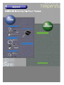
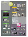
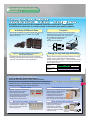
Cat.No.Y101-E1-03
CONTENTS
Product Lineup . . . . . . . . . . . . . . . . . . . . . . . . . . . . . . . . . .
Temperature Controller Selection 1 . . . . . . . . . . . . . . . . .
Temperature Controller Selection 2 . . . . . . . . . . . . . . . . .
Output Device Selection . . . . . . . . . . . . . . . . . . . . . . . . . . .
Input Device Selection . . . . . . . . . . . . . . . . . . . . . . . . . . . . .
Applications . . . . . . . . . . . . . . . . . . . . . . . . . . . . . . . . . . . . .
Selection Guide . . . . . . . . . . . . . . . . . . . . . . . . . . . . . . . . . .
Technical Information . . . . . . . . . . . . . . . . . . . . . . . . . . . . .
Glossary . . . . . . . . . . . . . . . . . . . . . . . . . . . . . . . . . . . . . . . .
Standards . . . . . . . . . . . . . . . . . . . . . . . . . . . . . . . . . . . . . . .
4
6
8
10
11
12
16
25
29
38
3
Cycle Control
Cycle Control Units
G32A-EA
G3PA
G3PC
ON/OFF Control
SSRs
Digital Temperature
Controllers
G3PB (Single-phase)
G3PB (Three-phase)
G3NA
Phase Control
Power Controllers
ES100P
ES100X
G3PX (Single-phase)
G3PX (Three-phase)
Modular Temperature
Controllers
E5ZN
Multi-point Temperature
Controllers
Block-type Switching
Power Supplies
S8TS
Data Recorder
E55A-E/-F
Interface Converters
K3SC
(DeviceNet)
Switching Power Supplies
S8VS
PLC Units
Heater Burnout Alarms K2CU
Intelligent Signal Processors
K3NH/K3MA-L
CJ1W-TC
C200H-TC/-TV/-PID
CQM1-TC
5
Temperature
Temperature Controller
Controller
Selection
Selection 11
Equipped with nearly all the standard functions required in Temperature
Controllers to allow use in a wide variety of machines and control panels.
A Variety of Different Sizes
Compact
The lineup includes the compact E5GN (48 24 mm)
and the E5AN (96 96 mm), which has a large
display and keys.
A depth of 78 mm allows these Temperature
Controllers to fit into thinner control panels
E5CJ
(except for the E5GN). The front panel
(48 48 mm)
of the E5GN has dimensions of
48 24 mm for double-size
display of PVs and SPs.
40 mm
E5GN
(48 24 mm)
Improvements in Basic Functions
and Performance
Equipped with the performance and functionality,
including auto-tuning and self-tuning, to fulfill almost
any kind of temperature control application.
Energy Savings and High Reliability
Unique power supply technology enables an energy
saving of 40% compared to existing models
(power consumption: approx. 7 VA). The suppression
of heat generation and improved reliability ensure at
least 3 years of use.
E5CN
(Approx. 7 VA) 40% energy saving
Existing models
(Approx. 12 VA)
(E5CJ)
(Power consumption)
For smaller installations...
Downsize the installation by using a Programmable
Terminal for both operation and display. These Temperature
Controllers are recommended for applications not requiring
setting and display at the front of the panel.
22.5 mm
Expansion According to Necessity
The Temperature Controller can be
replaced without changing the
wiring, meaning less work and
fewer wiring errors.
6
Modular Temperature Controllers
Less Maintenance Required
Simpler Setup
Ultra-slim model of width 22.5 mm.
Side connectors are used for
power supply and RS-485
connections between Units and so
wiring between the panel surface
and the panel interior is only
required for the display device.
E5ZN
The number of temperature input
points can be increased without
adding operating panels or
restructuring the control panel.
Temperature control can be
performed for 2 channels per Unit
up to a maximum of 32 channels.
Easier Software Development
Using the E5ZN-SDL to set
items that do not require
setting with an operating
panel eliminates the need for
software to make and display
multiple settings.
Setting
Display Unit
E5ZN-SDL
PV
SV
OUT1
OUT2 MANU STOP RMT
AT
SUB1
A
M
E5CK
PV
SV
OUT1
OUT2 MANU STOP RMT
AT
SUB1
A
M
E5CK
8
E5CS
E5C2
E5L
9
G32A
Applications
Fryer
A low-cost Temperature Controller that has
a process value display is required for the
temperature control of a fryer.
E5CN
Oil
Oil
Temperature
sensor
Alarm
output
Oil-flow sensor
Gas burner
E5CN
Shut-off
valve
Buzzer
Gas
Oil-flow sensor:
The oil-flow sensor detects the flow of oil and shuts off
the burner if there is a decrease in the quantity of oil flow.
Temperature Controller: The Temperature Controller is in ON/OFF control of the
oil temperature at 160°C. If the oil temperature exceeds
180°C, the alarm output turns ON, the buzzer goes off,
and the valve is shut-off.
Rack-type Oven
at a Bakery
Changes in temperature setting are
required for various types of bread.
E5EN
Heater
Temperature sensor
Bread
A
E5EN
Temperature
Controller
Example:
Set point 0 for bread A: 170°C
Set point 1 for bread B: 180°C
Set point 2 for bread C: 190°C
Set point 3 for bread D: 200°C
Max. 4 set points
Set value selector
Four set points can be stored in the memory of the E5EN,
any of which can be selected with ease.
Injection Molding
Machine
E5ZE
Changes in control temperature and
PID constants are required for various
types of products.
The control temperature and
PID constants are selected
according to the product type.
Mold
E5ZD
7 sensors
E5ZE
E5ZE
E5ZE
Banks
available
E5ZE
E5ZE
The bank is selected with the
Programmable Controller.
The E5ZE is a multipoint, single-board Temperature Controller
with 8 banks. Use the C200HX, C200HG, or C200HE
Programmable Controller to select the data in each bank, such
as control temperature and PID constant data for product
control.
The SYSMAC C200HX, C200HG, and C200HE Programmable
Controllers have a built-in protocol macro function.
12
Applications
Constant Temperature
Oven
Simple but precise temperature
control is required for a constant
temperature oven.
ES100P
ES100P
Heater
Temperature
Constant
temperature
oven
minutes
The temperature pattern is set in the ES100P Digital Controller
operating with a start signal.
Furnace
E5jK
High-precision temperature control
is required for a furnace.
ESI
BaF2 window
ESI
E5jK
Products
Furnace
Packing Machine
The E5jK Digital Controller and the ES1 Non-contact
Sensor are used in combination to check the
temperature of the product for precise quality control.
The temperature of the processed products can be
checked for precise quality control. Apply BaF2
infrared-transparent material to the windows.
Less space and wiring work are required
for packing machines.
CPM2C
E5ZN-2j
E5ZN
E5ZN-SCTjS
E5ZN-SDL
With the E5ZN Modular Temperature Controller, the
control panel can be downsized and wiring between the
panel surface and the panel interior is only required for
the display device. In addition, connecting a
CPM2C–CIF21 Simple Communications Unit eliminates
the need for communications programming.
13
Applications
Serial
Communications
Tunnel Furnace
•
Flexible expansion is possible in Unit–configured
installations.
•
Programming requirements can be reduced using
the CPM2C–CIF21.
•
Combining with a computer enables use of data
logging and recipe functions.
CPM2CCIF21
E5ZN
Advantage
CPM2C
Computer for data
maintenance
E5ZN-SDL
Applications
•
Baking furnace (tunnel furnace)
Conveyor control
Explanation
•
The temperature and conveyor control systems are
separate.
•
User maintenance is easy.
SSR
SSR
Tunnel
furnace
SP Ramp
Ceramic Baking Furnace
Advantage
•
SP ramp
Prevents workpieces from radical heating.
Target
value
Applications
•
Applications where the thermal shock is unfavorable.
•
Simple program control
SP ramp
set value
SP ramp time
Time
Explanation
•
The ceramic baking furnace is in temperature
control with a gas burner.
•
A smooth temperature rise is required because the
ceramic material may crack if there is a sudden
temperature rise.
E5CK
4 to 20 mA (transmission output)
Temperature
sensor
4 to 20 mA
(current output)
Recorder
Burner
14
Applications
Tunnel Furnace (Electric Furnace)
Remote SP
Start
Advantage
•
Reset
Uses external 4- to 20-mA analog signals as SP
values.
Pattern selection
Applications
•
E5AK
E5AK
Zone control of tunnel furnace
Explanation
•
The electric furnace is in zone control using the
remote SP function of the Digital Controllers.
•
Three Digital Controllers are used to make the
furnace temperature even.
•
Selectable patterns are stored in the ES100P. The
system is in operation with the start signal and
according to the selected pattern.
•
The remote SP function is in control of the three
zones with the same pattern.
Remote signal
Remote signal
ES100P
G3PX
Temperature
sensor
G3PX
Temperature
sensor
G3PX
Temperature
sensor
Electric
furnace
Heater
Heater
Heater
Water Tank Level Control (3-position Control)
Input Digital Filter
PV before filtered
Advantage
•
Smooths radical input changes.
Filtered PV
Applications
•
Applications with quick thermal response, if the
unstable process value unfavorably affects the
control of the systems.
•
A reduction in noise, if the noise unfavorably affects
the process value.
Input digital filter
E5AK
Dead band
Explanation
•
The water level of the tank is checked with a
supersonic level meter while the water supply and
drain pumps are in ON/OFF control.
•
The water surface undulates, thus making the
process value (PV) unstable. Therefore, an input
digital filter is applied to alleviate the fluttering of the
process value.
Time
Time
constant
Hysteresis
Hysteresis
Water
supply
Drainage
Target value
Level meter
Water supply
Drainage
15
Selection Guide
E5jN
Use
General-purpose models
Model type
Digital Temperature Controller
Model
E5jN
E5CN-U
Item
Standard/Communications type
Plug-in
Size
96 x 96
E5AN
Control
d
mode
ON/OFF
Yes
PID
---
2-PID
Yes
48 x 96
48 x 48
48 x 24
E5EN
E5CN
E5GN
48 x 48
E5CN-U
Auto-tuning function
Yes
Self-tuning function
Yes
Hysteresis in ON/OFF control
action
0.1 to 999.9 EU (in units of 0.1 EU)
Indication accuracy
Thermocouple:
(±0.5% of indicated value or ±1°C, whichever greater) ±1 digit max.
(see note)
Platinum resistance thermometer:
(±0.5% of indicated value or ±1°C, whichever greater) ±1 digit max.
Analog input: ±0.5% FS±1 digit max.
CT input: ±5% FS±1 digit max.
Input
Thermocouple: K, J, T, E, L, U, N, R, S, B
Platinum resistance thermometer: Pt100, JPt100
Infrared temperature sensor: 10 to 70°C, 60 to 120°C, 115 to 165°C, 160 to 260°C
Voltage input: 0 to 50 mV
Output
Relay, voltage, and current output (E5GN: Relay, voltage)
Relay, voltage
Heater burnout (not used with
current output)
Yes (E5AN, E5EN, E5CN)
---
Communication
RS-232C (E5AN/E5EN), RS-485 (E5AN/E5EN/E5CN/E5GN)
---
Supply voltage
100 to 240 VAC or 24 VAC/DC
Terminal configuration
Screw terminals
EMC
Conforms to EN55011 Group 1 class A, EN55011 Group 1 class A, EN61000-4-2, ENV50140,
ENV50141, EN61000-4-4
Approved standards
UL, CSA
Datasheet Cat. No.
H107: E5AN/EN/CN/GN Datasheet
Manual Cat. No.
H100:
H101:
H111:
H112:
H102:
Note:
16
Thermocouple:
(±1% of indicated value or
±2°C, whichever greater)
Platinum resistance
thermocouple:
(±0.5% of indicated value
or ±1°C, whichever
greater)
Plug-in
H109: E5CN-U Datasheet
E5CN User’s Manual
E5GN User’s Manual
E5EN User’s Manual
E5AN User’s Manual
E5AN/EN/CN/GN Communication Manual
This page provides information on main specifications only. Be sure to read the information on detailed specifications and precautions
before using the models listed here.
Selection Guide
E5jK
Use
General-purpose models
Model type
Digital Process Controller
Model
E5jK
Function
Standard
Item
Standard type
Size
96 x 96
E5AK
Control
mode
d
ON/OFF
Yes
PID
---
2-PID
Yes
PID with fuzzy
control
---
E5AK/E5EK
Position proportional
Communications type
48 x 96
53 x 53
E5EK
E5CK
96 x 96
E5AK
Standard type
Communications
type
48 x 96
53 x 53
96 x 96
48 x 96
96 x 96
48 x 96
E5EK
E5CK
E5AK
E5EK
E5AK
E5EK
Auto-tuning function
Yes
Self-tuning function
Yes
Hysteresis in ON/OFF control
action
0.01% to 99.99% FS (in units of 0.01%)
Indication accuracy
Thermocouple: (±0.3% of indicated value or ±1°C, whichever greater) ±1 digit max.
Platinum resistance thermometer: (±0.2% of indicated value or ±0.8°C, whichever greater) ±1 digit
max.
Analog input: ±0.2% FS ±1 digit max.
Input
K, J, T, L, U, N, R, S, B, W, PLII, JPt100, or PT100
Current or voltage input
Output (Optional)
Relay, SSR, voltage, linear voltage, and linear current
output
Relay output
Heater burnout (not used with
current output)
Yes (E5AK/E5EK)
Loop burnout alarm is available (E5AN/E5EK/E5CK)
---
Communication
RS-232C, RS-422, RS-485
Supply voltage
100 to 240 VAC or 24 VAC/DC at 50/60 Hz
Terminal configuration
Screw terminals
EMC
Conforms to EN50081-2, EN50082-2
Approved standards
UL, CSA
Datasheet Cat. No.
H084: E5AK/EK Digital Controller DS
H079: E5CK Digital Controller Cat.
Manual Cat. No.
H083: E5AK User’s Manual
H085: E5EK User’s Manual
H078: E5CK User’s Manual
Note:
This page provides information on main specifications only. Be sure to read the information on detailed specifications and precautions
before using the models listed here.
17
Selection Guide
E5jK-T Programmable Type
Use
General-purpose models
Model type
Digital Process Controller
Model
E5jK-T programmable type
Function
Standard
Item
Standard type
Size
96 x 96
Position proportional
Communications type
48 x 96
96 x 96
48 x 96
53 x 53
E5AK-TA
Control
mode
d
ON/OFF
Yes
PID
---
2-PID
Yes
PID with fuzzy
control
---
E5CKE5EK-TA TA
Standard type
96 x 96
48 x 96
E5AK-TA
E5EK-TA
53 x 53
E5AK-TA
E5CKE5EK-TA TA
Communications
type
96 x 96
E5AK-TA
48 x 96
E5EK-TA
Auto-tuning function
Yes
Self-tuning function
Yes
Hysteresis in ON/OFF control
action
0.01% to 99.99% FS (in units of 0.01%)
Indication accuracy
Thermocouple: (±0.3% of indicated value or ±1°C, whichever greater) ±1 digit max.
Platinum resistance thermometer: (±0.2% of indicated value or ±0.8°C, whichever greater) ±1 digit
max.
Analog input: ±0.2% FS ±1 digit max.
Input
K, J, T, L, U, N, R, S, B, W, PLII, JPt100, or PT100
Current or voltage input
Output (Optional)
Relay, SSR, voltage, linear voltage, and linear current
output
Relay output
Heater burnout (not used with
current output)
Yes (E5AK/E5EK)
Loop burnout alarm is available (E5AN/E5EK/E5CK)
---
Communication
RS-232C, RS-422, RS-485
Supply voltage
100 to 240 VAC or 24 VAC/DC at 50/60 Hz
Terminal configuration
Screw terminals
EMC
Conforms to EN50081-2, EN50082-2
Approved standards
UL, CSA
Datasheet Cat. No.
H087: E5jK-T Digital Controller DS
Manual Cat. No.
H088: E5AK User’s Manual (Programmable Type)
H089: E5EK User’s Manual (Programmable Type)
H090: E5CK User’s Manual (Programmable Type)
Note:
18
This page provides information on main specifications only. Be sure to read the information on detailed specifications and precautions
before using the models listed here.
Selection Guide
E5CS
Use
General-purpose models
Model type
Digital Temperature Controller
Model
E5CS
E5CS-X
Item
Plug-in
Basic
Size
48 x 48
Control
d
mode
ON/OFF
Yes
PID
Yes
2-PID
---
PID with fuzzy
control
---
Auto-tuning function
---
Self-tuning function
Yes
Hysteresis in ON/OFF control
action
0.2% FS fixed
Indication accuracy
±1% FS ± 1 digit max.
Input
K, J, L, JPt100, Pt100 or thermistor
Output
Relay or voltage output
Supply voltage
100 to 240 VAC or 24 VAC/VDC at 50/60 Hz
Terminal configuration
Plug-in model
EMC
Conforms to EN50081-2, EN50082-2
Approved standards
UL, CSA
Datasheet Cat. No.
H042
Note:
48 x 48
±0.5% FS ± 1 digit max.
Screw terminals
H032
This page provides information on main specifications only. Be sure to read the information on detailed specifications and precautions
before using the models listed here.
19
Selection Guide
E5C2, E5L
Use
General-purpose models
Model type
Analog Temperature Controller
Digital Thermometer
Model
E5C2
E5L
Item
Basic
Basic
Size
48 x 48
Digital
Thermometer
(with external
setting device)
Control
mode
d
ON/OFF
Yes
PID
P action
2-PID
---
PID with fuzzy
control
---
External
setting
device
Panel
meter
---
Auto-tuning function
---
Self-tuning function
---
Hysteresis in ON/OFF control
action
0.5% FS fixed
Variable
Indication accuracy
±2% FS max.
±2% FS max.
Input
K, J, JPt100, and THE
THE (element-compatible thermistor)
Output
Relay output
Supply voltage
100/110, 200/220 VAC at 50/60 Hz
Terminal configuration
Plug-in model
EMC
Conforms to EN50081-2, EN50082-2
---
Approved standards
UL, CSA
---
Datasheet Cat. No.
H081
H020
Note:
20
100, 110, 200, 220 (individual) VAC at 50/60 Hz
(common)
This page provides information on main specifications only. Be sure to read the information on detailed specifications and precautions
before using the models listed here.
Selection Guide
E5LC, E5LD
Use
Economy models
Model type
Temperature Display
Digital Thermometer
Model
E5LC
E5LD
Item
Temperature display only
ON/OFF control type
ON/OFF
---
Yes
PID
---
2-PID
---
PID with fuzzy
control
---
Size
Control
d
mode
Auto-tuning function
---
Self-tuning function
---
Hysteresis in ON/OFF control
action
---
0.5 to 9.0°C (in units of 0.5°C)
Setting accuracy
---
±1°C + 1 digit max.
Indication accuracy
±1°C ± 1 digit max.
Input
Mono-block thermistor
Output
---
Heater burnout (not used with
current output)
---
Supply voltage
---
100, 200 VAC (depends on model) at 50/60 Hz
(common)
Terminal configuration
---
Screw terminals
EMC
Conforms to EN50081-2, EN50082-2
---
Approved standards
---
Datasheet Cat. No.
H035
Note:
Relay
This page provides information on main specifications only. Be sure to read the information on detailed specifications and precautions
before using the models listed here.
21
Selection Guide
E5ZE, E5ZD
Use
Multipoint control models
Model type
Multipoint Temperature Controller
Model
E5ZE
Item
---
E5ZD
E5ZD-8F
Size
Control
d
mode
ON/OFF
Yes
PID
---
2-PID
---
Yes
---
PID with fuzzy
control
Yes
---
Yes
Auto-tuning function
Yes
Self-tuning function
---
Hysteresis in ON/OFF control
action
0.0 to 99.9°C/°F for ON/OFF control only (in units of 0.1°C/°F)
Indication accuracy
Thermocouple:
±0.3% or ±2°C of indicated
value (whichever is larger) ±
1 digit max.
Platinum resistance
thermometer:
±0.3% or ±0.8°C (whichever is
larger) ± 1 digit max.
±0.5% FS ± 1 digit max.
Input
K, J, R, S, T, E, B, N, L, U,
W/Re5-26, PT II, Pt100, or
JPt100
K, J, JPt100, or Pt100
Output
Voltage or current output
Voltage or open collector output
Heater burnout (not used with
current output)
Yes
Supply voltage
24 VDC
Terminal configuration
Screw terminals
Dedicated terminal
EMC
Conforms to EN50081-2,
EN50082-2
---
Approved standards
---
Datasheet Cat. No.
H075
H060
Manual Cat. No.
H077: E5ZE Communications
Manual
H076: E5ZE Operation Manual
Z042:
Z084:
Note:
22
E5ZD Operation Manual (European Version)
E5ZD-jV Operation Manual (European Version)
This page provides information on main specifications only. Be sure to read the information on detailed specifications and precautions
before using the models listed here.
Selection Guide
E5ZN
Use
Din track mounting models
Model type
Module Temperature Controller
Model
E5ZN
Item
Communications type
Size
(Terminal Unit sold separately)
Control
d
mode
ON/OFF
Yes
PID
---
2-PID
Yes
Setting display
Auto-tuning function
Self-tuning function
---
Hysteresis in ON/OFF control
action
0.1 to 999 EU (in units of 0.1 EU)
Indication accuracy
Thermocouple: (±0.5% of indicated value or ±1°C, whichever greater) ±1 digit max.
Platinum resistance thermometer: (±0.5% of indicated value or ±1°C, whichever greater) ±1 digit
max.
Analog input: ±0.5% FS ±1 digit max.
Input
Thermocouple: K, J, T, E, L, U, N, R, S, B
Infrared temperature sensor: ES1A series
Voltage input: 0 to 50 mV
Platinum resistance thermometer: Pt100, JPt100
Output
Voltage, transistor, or current output
Heater burnout (not used with
current output)
Yes
Supply voltage
24 VAC/DC
Terminal configuration
Screw terminal (Terminal Unit sold separately)
EMC
EN61326
Approved standards
UL, CSA
Datasheet Cat. No.
H116
Manual Cat. No.
H113
Note:
This page provides information on main specifications only. Be sure to read the information on detailed specifications and precautions
before using the models listed here.
23
Selection Guide
ES100
Use
Current and voltage input models
Model type
Process Controller
Model
ES100X, ES100P
Item
Digital Controller
Size
Control
d
mode
ON/OFF
Yes
PID
---
2-PID
Yes
PID with fuzzy
control
Yes
96 x 96
96 x 96
ES100X (fixed value type)
ES100P (programmable type)
Auto-tuning function
Yes
Self-tuning function
---
Hysteresis in ON/OFF control
action
0.01% to 99.99% FS in 0.01% FS increments
Indication accuracy
±0.1% FS ± 1 digit max.
Input
K, J, T, E, R, S, B, N, L, U, PL II, W, Pt100, or JPt100 voltage or current input
Output
Output Unit available to relay, SSR, voltage, and current output.
Heater burnout (not used with
current output)
Yes
Supply voltage
100 to 240 VAC 50/50 Hz
Terminal configuration
Screw terminals
EMC
---
Approved standards
UL, CSA
Datasheet Cat. No.
H058
Manual Cat. No.
H072: ES100 Communications Guide
H069: ES100P Digital Controller Programmer
User’s Guide
H115: ES100 Support Software ES/TOOLS for Windows Operation Manual
H070: ES100X Digital Controller User’s Manual
Note:
This page provides information on main specifications only. Be sure to read the information on detailed specifications and precautions
before using the models listed here.
Watertight Covers
Model
Y92A-jj
Size
96 x 96
72 x 72
21.9
48 x 96
21.9
(2)
21.9 14
(2)
(2)
69
87.7 79.2
107.7
131.7
48 x 48
21.9
(2)
131.7
12
67.6
91.6
115.6
Y92A-96N
Degree of protection
IP66 or NEMA4 (indoors)
Datasheet Cat. No.
Q088
24
29.4
67.6
29.4
Y92A-72N
29.4
Y92A-49N
Y92A-48N
Technical Information
Configuration Example of Temperature Control
The following is an example of the configuration of temperature control.
•
•
•
Relay output
Voltage output
Current output
•
•
•
•
•
•
SSR
Cycle controller
Power controller
Thermocouple
Platinum resistance thermometer
Thermistor
Controlled object
Temperature
Controller
Control signal
Controller
Temperature Sensor
The Temperature Sensor consists
of an element protected with a
pipe. Locate the element, which
converts temperatures into electric
signals, in places where
temperature control is required.
Electronic Temperature Controller
The Electronic Temperature Controller
is a product that receives electric signal
input from the temperature sensor,
compares the electric signal input with
the set point, and outputs adjustment
signals to the Controller.
Controller
The Controller is used to heat up or
cool down furnaces and tubs using a
device, such as a solenoid or fuel valve,
to switch electric currents supplied to
heaters or coolers.
Temperature Control
3. The response is slow in reaching the
set point.
Temperature
Temperature
1. The temperature stabilizes after overshooting several times.
Time
Time
2. Proper response
Temperature
The set point is input into the Temperature
Controller in order to operate the Temperature Controller. The time required for stable
temperature control varies with the controlled object. Attempting to shorten the response time will usually result in the overshooting or hunting of temperature. When reduce the overshooting or hunting of temperature, the response time must not be shortened. There are applications that require
prompt, stable control in the waveform
shown in (1) despite overshooting. There are
other applications that require the suppression of overshooting in the waveform shown
in (3) despite the long time required to stabilize temperature. In other words, the type of
temperature control varies with the application and purpose. The waveform shown in (2)
is considered to be a proper one for standard
applications.
Time
25
Technical Information
Characteristics of the Controlled Object
Before selecting the Temperature Controller and Temperature Sensor models, it is necessary to understand the thermal characteristics of the
controlled object for proper temperature control.
Heat capacity, which indicates the degree of ease of
heating, varies with the capacity of the furnace.
Static
characteristics
Static characteristics, which indicate the capability of
heating, vary with the capacity of the heater.
Dynamic
characteristics
Dynamic characteristics, which indicate the startup
characteristics (i.e., excessive response) of heating, vary
with the capacities of the heater and furnace that affect
each other in a complex way.
External disturbances are causes of temperature
change. For example, the opening or closing of the door
of a constant temperature oven will be a cause of
external disturbance thus creating a temperature
change.
External
disturbances
ON/OFF Control Action
As shown in the graph below, if the process
value is lower than the set point, the output
will be turned ON and power will be supplied
to the heater. If the process value is higher
than the set point, the output will be turned
OFF with power to the heater shut off. This
control method is called ON/OFF control
action, in which the output is turned ON and
OFF on the basis of the set point to keep the
temperature constant. In this operation, the
temperature is controlled with two values
(i.e., 0% and 100% of the set point). Therefore, the operation is also called two-position
control action.
Characteristics of
ON/OFF control action
Hysteresis
P Action
P action (or proportional control action) is
used for obtaining the output in proportion to
the input.
The Temperature Controller in P action has a
proportional band with the set point in the
proportional band. The control output varies
in proportion to the deviation in the proportional band. In normal operation, a 100%
control output will be ON if the process value
is lower than the proportional band. The control output will be decreased gradually in proportion to the deviation if the process value is
within the proportional band, and a 50% control output will be ON if the set point coincides
with the process value (i.e., there is no deviation). This means P action ensures smooth
control with minimal hunting compared with
the ON/OFF control action.
Set
point
Time
Control output
Proportional
control action
Example:
If a Temperature Controller with a temperature range of 0° to 400°C has a 5% proportional band, the width of the proportional
band will be converted into a temperature
range of 20°C. In this case, provided that the
set point is 100°C, a full output is kept turned
ON until the process value reaches 90°C,
and the output is OFF periodically when the
process value exceeds 90°C. When the process value is 100°C, there will be no difference in time between the ON period and the
OFF period (i.e., the output is turned ON and
OFF with the same interval).
Control output
Characteristics of
controlled object
Heat capacity
A narrow proportional
band is set.
A wide proportional
band is set.
Set point
A narrow proportional
band is set.
Heater
Temperature
Set
point
Set
point
Offset
Proportional band
A wide proportional
band is set.
Time
26
Technical Information
I Action
D Action
I action (or integral control action) is used for
obtaining the output in proportion to the time
integral value of the input.
P action causes an offset. Therefore, if proportional control action and integral control
action are used in combination, the offset will
be reduced as the time goes by until finally
the control temperature will coincide with the
set point and the offset will cease to exist.
Offset
PI (proportional
and integral
control) action
Time
PID control
External
disturbance
P (proportional
control) action
only
Time
A short integral time is set.
A long integral time is set.
Control output
Control output
PID control is a combination of proportional,
integral, and derivative control actions, in
which the temperature is controlled smoothly
by proportional control action without hunting, automatic offset adjustment is made by
integral control action, and quick response to
an external disturbance is made possible by
derivative control action.
PD (proportional
and derivative
control) action
P (proportional
control) action
only
Set point
Set point
Offset ceases
to exist.
PID Control
D action (or derivative control action) is used
for obtaining the output in proportion to the
time derivative value of the input.
Proportional control action corrects the result
of control and so does integral control action.
Therefore, proportional control action and integral control action respond slowly to temperature change, which is why derivative
control action is required. Derivative control
action corrects the result of control by adding
the control output in proportion to the slope of
temperature change. A large quantity of control output is added for a radical external disturbance so that the temperature can be
quickly in control.
A long derivative time is set.
A short derivative time is set.
Time
A short integral time is set.
Time
Set
point
A long derivative time is set.
Set
point
A long integral time is set.
A short derivative time is set.
Time
Time
27
Technical Information
2-PID Control
Conventional PID control uses a single control block to control the responses of the Temperature Controller to a target value and external disturbances. Therefore, the response
to the target value will oscillate due to overshooting if importance is attached to the response to external disturbances with the P
and I parameters set to small values and the
D parameter set to a large value in the control
block. On the other hand, if importance is attached to the response to the target value
(i.e., the P and I parameters are set to large
values), the Temperature Controller will not
be able to respond to external disturbances
quickly. It will be impossible to satisfy both the
types of responses in this case.
2-PID control eliminates this weakness while
retaining the strengths of PID control, thus
making it possible to improve both types of
responses.
PID Control
2-PID Control
Response to the target value will become
slow if response to the external disturbance
is improved.
Response to
target value
Response to
external disturbance
Controls both the target value response and
external disturbance response.
Response to the external disturbance will
become slow if response to the target value is
improved.
PID with Fuzzy Control
By adding fuzzy control to PID control, further
improvement in response to external disturbances is possible. PID and fuzzy control
usually operate as PID control. If there is external disturbance, fuzzy control will operate
in combination with PID control.
OMRON’s fuzzy control estimates temperature change from the difference between the
deviation (i.e., the difference between the set
point and process value) and deviation
change rate, and then makes the delicate adjustment of the control output.
PID control
Set
point
External
disturbance
An increase in output.
PID and fuzzy control
Suppresses the
output to eliminate
overshooting.
Control on the basis of the deviation and deviation change rate.
28
Response to the target value.
Response to external disturbance
PID control
PID and fuzzy control
Glossary
Control
Hysteresis
Hunting and Overshooting
Derivative Time
ON/OFF control action turns the output ON
or OFF on the basis of the set point. This
means the output frequently changes according to minute temperature changes,
which shortens the life of the output relay or
unfavorably affects some devices connected
to the Temperature Controller. Therefore, a
margin is prepared between the ON and OFF
operations. This margin is called hysteresis.
ON/OFF control action often involves the waveform shown in the following graph. A temperature rise in excess of the set point after
temperature control starts is called overshooting. Temperature oscillation near the
set point is called hunting. Improved temperature control is to be expected if the degrees
of overshooting and hunting are low.
Derivative time is the period required for a
ramp-type deviation in derivative control
(e.g., the deviation shown in the following
graph) to coincide with the control output in
proportional control action. The longer the
derivative time is, the stronger the derivative
control action is.
Overshooting
PD action
(with a short derivative time)
PD action
(with a long derivative
time)
Example:
If the Temperature Controller with a temperature range of 0°C to 400°C has a 0.2% hysteresis, D will be 0.8°C. Therefore if the set
point is 100°C, the output will turn OFF at a
process value of 100°C and will turn ON at a
process value of 99.2°C.
Control Cycle and
Time-proportioning Control
Action
The control output will be turned ON intermittently according to a preset cycle if P action is
used with a relay or SSR. This preset cycle is
called control cycle and this control method is
called time-proportioning control action.
Offset
Set point
Temperature
Set point
Proportional control action causes an error in
the process value due to the heat capacity of
the controlled object and the capacity of the
heater, which results in a small discrepancy
between the process value and set point in
stable operation. This error is called offset.
Offset may exist above or below the set point.
Proportional
band
Control output
Hunting
Temperature
Offset
PD Action and Derivative Time
Deviation
D: Hysteresis
Set point
Control output
Hysteresis
Hunting and Overshooting in ON/OFF
Control Action
P action
D2 action
(with a short
derivative time)
D1 action
TD:
Derivative
time
(with a long derivative time)
Actual
temperature
The higher the temperature is,
the shorter the ON period is.
Proportional band
T: Control cycle
Offset
Control output =
TON
TON + TOFF
x 100 (%)
TON: ON period
TOFF: OFF period
Example;
If the control cycle is 10 s with an 80% control
output, the ON and OFF periods will be the
following values.
TON: 8 s
TOFF: 2 s
29
Glossary
ARW Function
Integral Time
ARW stands for anti-reset windup.
There is usually a large deviation (i.e., a large
difference between the process value and
set point) when the Temperature Controller
starts operating. Integral control action in PID
control is repeated until the temperature
reaches the set point. As a result, an excessive integral output causing overshooting is
output. To prevent this, the ARW function
sets a limit to restrict the output rise in integral
control action. In normal control operation,
the integral output is eliminated until the process value reaches the proportional band.
Integral time is the period required for a steptype deviation in integral control (e.g., the
deviation shown in the following graph) to
coincide with the control output in proportional control action. The shorter the integral time
is, the stronger the integral control action is. If
the integral time is too short, however, hunting may result.
Overshooting due to
excessive integral output.
Deviation
Temperature or
deviation
PI Action and Integral Time
PI action (with a short integral time)
PI action
(with a long integral time)
Control output
Set point
Proportional band
Deviation
Integral output
Time
P action
T1: Integral
time
(with a short integral time)
(with a long integral time)
Initial integral output with
ARW function disabled.
Initial integral
output with ARW
function enabled.
Time
Auto-tuning
Marginal Sensitivity Method
Limit Cycle Method
Proportional control action starts from the
start point A in this method. Narrow the width
of the proportional band until the temperature
starts to oscillate. Then obtain the PID
constants from the value of the proportional
band and the oscillation cycle T at that time.
ON/OFF control action starts from the start
point A in this method. Then obtain the PID
constants from the hunting cycle T and oscillation D.
Hunting cycle
Time
Step Response Method
Set point
The value most frequently used must be the
set point in this method. Calculate the maximum temperature ramp R and the dead time
L from a 100% step-type control output. Then
obtain the PID constants from R and L.
Time
30
Oscillation
Set point
Set point
PID constants for temperature control vary in
value and combination according to the characteristics of the controlled object. There has
been a variety of conventional methods suggested and implemented to obtain PID
constants from the waveforms of temperatures to be controlled by the Temperature
Controller in actual operation. Among them,
auto-tuning methods make it possible to obtain PID constants suitable to a variety of objects. Auto-tuning methods include the step
response, marginal sensitivity, and limit cycle
methods.
Marginal sensitivity
method
Time
Glossary
Readjustment of PID Constants
PID constants calculated in auto-tuning operation normally do not cause problems except for some particular applications, in
which case, refer to the following to readjust
the PID constants.
Response to Change in Integral Time
Response to Change in Derivative Time
Wider
Wider
Set
point
Set
point
Response to Change in Proportional
Band
Wider
Set
point
It is possible to reduce hunting, overshooting, and undershooting although a comparatively long startup time and set time will be required.
The process value reaches the set point within a comparatively short time with comparatively small amounts of overshooting and undershooting although fine-cycle hunting will
result due to the change in process value.
Narrower
It is possible to suppress overshooting although a comparatively long startup time and
set time will be required.
Narrower
Set
point
Set
point
Narrower
Set
point
The process temperature reaches the set
point within a comparatively short time although overshooting, undershooting, and
hunting will result.
It will take a comparatively long time for the
process value to reach the set point with
heavy overshooting and undershooting.
The process value reaches the set point within a comparatively short time and keeps the
temperature stable although overshooting
and hunting will result until the temperature
becomes stable.
Fuzzy Self-tuning
PID constants must be determined according to the controlled object for proper temperature control. The conventional Temperature
Controller incorporates an auto-tuning function to calculate PID constants, in which
case, it will be necessary to give instructions
to the Temperature Controller to trigger the
auto-tuning function. Furthermore, if the limit
cycle method is adopted, temperature disturbance may result. The Temperature Controller in fuzzy self-tuning operation determines
the start of tuning and ensures smooth tuning
without disturbing temperature control. In
other words, the fuzzy self-tuning function
makes it possible to adjust PID constants according to the characteristics of the controlled object.
Fuzzy Self-tuning in 3 Modes
• PID constants are calculated by tuning at
the time of change in the set point.
•
When an external disturbance affects the
process value, the PID constants will be
adjusted and kept in a specified range.
•
If hunting results, the PID constants will
be adjusted to suppress the hunting.
Auto-tuning Method of a Conventional
Temperature Controller
Auto-tuning Function: Automatically
calculates the appropriate PID constant
for controlling objects.
Features:
1. Tuning will be performed when the
AT instruction is given.
2. The limit cycle signal is generated to
oscillate the temperature before
tuning.
Self-tuning Function
Self-tuning (ST) Function: A function to
automatically calculate optimum PID
constants for controlled objects.
Features:
1. Whether to perform tuning or not is
determined by the Temperature
Controller.
2. No signal disturbing the process
value is generated.
External
disturbance 1
Target
value
PID gain
calculated.
External
disturbance 2
Temperature
in control
Temperature
in control
ST starts.
Target
value
AT starts.
Temperature
oscillated.
PID gain
calculated.
AT
instruction
31
Glossary
Self-tuning Function
Fine-tuning Function
Set point
(Applicable Model: E5CS)
The self-tuning function is incorporated by
E5CS Digital Temperature Controller. The
function makes it possible to calculate and
use an optimum proportional band automatically according to change in the temperature.
(Applicable Models: ES100X, ES100P)
The fine-tuning function is incorporated by
the ES100 Digital Controller. Tuning is a delicate and troublesome job. The fine-tuning
function performs fuzzy logic calculations to
adjust the PID constants after the degrees of
requirements for suppressing overshooting
and hunting and improvements in response
are set.
Setting of Fine-tuning Requirements
Overshooting
Time
In self-tuning
operation
Quick response
Hunting
PID Control and Tuning Methods
Type of PID control
Model
PID
2-PID
PID with fuzzy control
AT, ST
E5jN
AT, ST
E5jK
E5CS
ST*
E5ZD
AT
AT
E5ZE
AT
ES100X
AT, FT
ES100P
AT. FT
Note:
ST stands for fuzzy self-tuning function, ST* stands for self-tuning function, FT stands for fine-tuning function, and AT stands for autotuning function.
Control Output
ON/OFF output
Control
output
Relay output
Contact relay output used for control methods with
comparatively low switching frequencies.
SSR output
Non-contact solid-state relay output for switching 1 A
maximum.
Voltage output
ON/OFF pulse output at 5, 12, or 24 VDC externally
connected to a high-capacity SSR.
Current output
Continuous 4- to 20-mA or 0- to 20-mA DC output
used for driving power controllers and electromagnetic
valves. Ideal for high-precision control.
Voltage output
Continuous 0 to 5 or 0 to 10 VDC output used for
driving pressure controllers. Ideal for high-precision
control.
Linear output
32
Glossary
Connection Example of Temperature Controller and SSR
Electronic Temperature Controller
Load
Voltage
output
terminals
for driving
SSR
Heater
Load power supply
Directly connectable
Temperature Controller at 12-VDC
Output with 40 mA
E5AN/E5EN
E5jK
(Excluding E5CK)
ES100 Series
Number of SSRs
connectable in
parallel
5
3
G3PC (Built-in Failure Detection Function)
20 A at 240 VAC
Rated input voltage:
12 to 24 VDC
Miniature, slim model with a
mono-block construction and
built-in radiator
G3PB (Single-phase)
15 A, 25 A, 35 A, or 45 A at 240 VAC
5
3
Rated input voltage:
12 to 24 VDC
Subminiature, slim model with a
mono-block construction and
built-in radiator
5
3
Temperature Controller at 12-VDC
Output with 20 mA
E5CN
E5CN-U
12 to 24 VDC
Three-phase control with a
mono-block construction and
built-in radiator
E5GN
5
3
G3PA
10 A, 20 A, 40 A, or 60 A at 240 VAC
20 A or 30 A at 400 VAC
5 to 24 VDC
Miniature, slim model with a
mono-block construction and
built-in radiator
E5ZN
E5CS
G3PB (Three-phase)
15 A, 25 A, 35 A, or 45 A at
240/400 VAC
E5CK
5
3
Note: The number of SSRs that can be connected in parallel can be obtained as follows:
Number of SSRs connectable=A B B
A: Maximum load current at the voltage output (for driving SSRs) of each Temperature
Controller
B: Input impedance of SSRs
* 4 Units for
400 VAC
models.
G3NA
at 240-V output with 5 A, 10 A, 20 A,
or 40 A at 240 VAC,
10 A, 20 A, or 40 A
at 480 VAC
5 to 24 VDC
Standard model with screw
terminals
G3NE
5A, 10A, or 20 A at 240 VAC
2
12 VDC
1
Compact, low-cost model
with tab terminals
G3NH
75A or 150 A at 440 VAC
8
4
5 to 24 VDC
Ideal for high-power
heater control
33
Glossary
Alarm
Standby Sequence Alarm
The Temperature Controller compares the
process value and the preset alarm value,
turns the alarm signal ON, and displays the
type of alarm in the preset operation mode.
It may be difficult to keep the process value
outside the specified alarm range in some
cases (e.g., when starting up the Temperature Controller) and as a result the alarm
turns ON abruptly. This can be prevented
with the standby sequential function of the
Temperature Controller. This function makes
it possible to ignore the process value right
after the Temperature Controller is turned on
or right after the Temperature Controller
starts temperature control. In this case, the
alarm will turn ON if the process value enters
the alarm range after the process value has
been once stabilized.
Deviation Alarm
The deviation alarm turns ON according to
the deviation from the set point in the Temperature Controller.
Setting Example
Alarm temperature is set to 110°C.
Alarm set
point: 10 °C
Set point (SV):
100°C
Heater Burnout Alarm
(Single-phase Use Only)
Many types of heaters are used to raise the
temperature of the controlled object. The CT
(Current Transformer) is used by the Temperature Controller to detect the heater current. If power interruption is caused by heater
burnout, the Temperature Controller will
detect the heater burnout from the CT and
will output the heater burnout alarm.
Current value
Alarm
Heater burnout alarm
Heater burnout
Example of Alarm Output with Standby
Sequence Set
Temperature Rise
Alarm value:
110°C
Upper-limit
alarm set
The alarm set point in the above example is
set to 10°C.
Absolute-value Alarm
The absolute-value alarm turns ON according to the alarm temperature regardless of
the set point in the Temperature Controller.
Setting example
Alarm temperature is set to 110°C.
Alarm set point
Heater current waveform
(CT waveform)
Set point
The wires connected to the
Temperature Controller has no polarity.
Lower-limit
alarm set
Alarm
output
Temperature Drop
Upper limit
alarm set
Current
Transformer
(CT)
Control output
Heater
Switch
Set point
Set point (SV):
100°C
Alarm value:
110°C
The alarm set point in the above example is
set to 110°C.
Proportional Alarm
The proportional alarm enables simple heating and cooling control, in which the control
output of the Temperature Controller is used
for heating and the alarm output is used as
cooling control output. The 0% control output
is turned ON with the alarm value and the
100% control output is turned ON with the
proportional upper limit, between which the
control output changes linearly.
Lower limit
alarm set
Alarm
output
Alarm Latch
Applicable Models: E5jN
An alarm will usually turn OFF if the process
value is not within the specified alarm range.
The latch alarm function makes it possible to
keep the alarm output turned ON once the
alarm is triggered.
Upper-limit
alarm set
Set point
Alarm
output
Alarm set
point
LBA
Set point (SV)
Alarm value
Changes linearly
34
Applicable Models: E5jK
The LBA (loop burnout alarm) is a function to
turn the alarm signal ON by assuming the occurrence of control loop failure if there is no
input change with the control output set to the
highest or lowest value. Therefore, this function can be used to detect control loop errors.
Glossary
Temperature Sensor
Cold Junction Compensating
Circuit
The thermocouple generates a thermo-electromotive force according to the difference in
temperature between the hot junction and
cold junction. The temperature sensor data
will change if there is any change in the temperature of the cold junction regardless of
whether there is any change in the temperature of the hot junction. Therefore, another
temperature sensor is employed to detect
the temperature of the cold junction connected to the thermocouple and make an
electrical compensation so that the temperature of the cold junction will be always 0°C.
This compensation is called cold junction
compensation.
Compensating Conductor
Input Compensation
An actual application has a sensing point that
may be located far away from the Temperature Controller. Special-conductor thermocouples are expensive. Therefore, the compensating conductor is connected to the thermocouple in such a case. The compensating
conductor must be in conformity with the
characteristics of the thermocouple, otherwise precise temperature sensing will not be
possible.
A preset point is added to or subtracted from
the temperature detected by the temperature
sensor of the Temperature Controller to display the process value. The difference between the detected temperature and displayed temperature is set as an input compensation value.
Compensating
conductor
Connection
terminal
Terminal
Furnace
Temperature
Controller
Terminal
Temperature
Controller
Sensing
point
350°C
Example of Compensating Conductor
Use
Cold junction
compensating circuit
The thermo-electromotive force VT is calculated from the following formula:
VT = K (350 – 20)
Condition:
The terminal temperature is 20°C.
VT = K (350 – 20) + K S 20 = K S 350
Thermo-electromotive
force of thermocouple
Thermo-electromotive force
generated by cold junction
compensating circuit
K (350 – 30) + K (30 – 20) +K S 20 + K S
350
Thermo-electromotive
force of thermocouple
Thermo-electromotive
force generated by
cold junction
compensating circuit
Thermo-electromotive force
through compensating
conductor
Three-wire Resistance
Thermometer
The three-wire platinum resistance thermometer is used by OMRON’s Temperature
Controller. One of the resistance conductors
of the three-wire resistance thermometer is
connected to two wires and the other resistance conductor is connected to another
wire, the wiring of which eliminates the influence of the resistance of the extended lead
wires.
Input compensation value: 10°C
(Displayed value is 120°C)
(120 – 110 = 10)
Platinum Resistance
Thermometer
The resistance of a metal will increase if the
temperature of the metal increases. This is
especially true if the metal is platinum. The
platinum resistance thermometer makes use
of the nature of platinum (e.g., its resistance
increases with the temperature rise) by incorporating a fine platinum wire wound around a
mica or ceramic plate.
Thermocouple
A thermocouple consists of two different metal wires with the ends connected together. If
the two contacts are different in temperature,
the thermocouple will generate a voltage
called thermo-electromotive force. The power of thermo-electromotive force depends on
the metals. The temperature sensor making
use of this voltage as input to the Temperature Controller is called a thermocouple.
Hot Junction and Cold Junction
A thermocouple has hot junction and cold
junction. The hot junction is for temperature
sensing and the cold junction is connected to
the Temperature Controller.
Connection of Three-wire Platinum
Resistance Thermometer
Platinum resistance thermometer
Metal A
Hot
junction
Temperature
Controller
Metal B
Cold
(reference)
junction
(0°C)
35
Glossary
Output
Position-proportioning Control
The Temperature Controller in reverse operation will increase control output if the process value is lower than the set point (i.e., if
the Temperature Controller has a negative
deviation).
This control is also called ON/OFF servo
control. If a valve with a control motor is applied to temperature control with the Temperature Controller and a potentiometer, the
Temperature Controller will read the valve
opening from the potentiometer and will turn
the open and close signals ON along with
control output for temperature control.
Control output (%)
Reverse Operation
Low
Set point
Temperature Controller in
positionproportioning control.
High
Open
Controlled
object
Close
Potentiometer
reading valve
opening.
Direct Operation
Control output (%)
The Temperature Controller in normal operation will increase control output if the process
value is higher than the set point (i.e., if the
Temperature Controller has a positive deviation).
Set point
Low
High
Transfer Output
The Temperature Controller with current output independent from control output is available. The process value or set point within
the available temperature range of the Temperature Controller is converted into 4- to
20-mA linear output that can be input into recorders to keep the results of temperature
control on record. The upper and lower limits
can be set for transfer output in the E5CK
with transfer output board. Therefore, the
transmission output between the upper and
lower limits will be turned ON if the E5CK with
transfer output board is used.
Heating and Cooling Control
The controlled object may be in heating and
cooling control if the temperature control of
the controlled object is difficult with heating
alone. A single Temperature Controller has
heating control output and cooling control
output.
Temperature
Controller with
transfer output
Recorder
Heating
Cooling
Heating and Cooling Outputs
Heating
output
Cooling
output
Temperature sensor
Controlled
object
Heating
output
Cooling
output
Transmission output
Temperature
Controller in
heating and
cooling
control
Process value
Lower limit
Upper limit
Possible setting range
Set point
36
Set point
Glossary
Setting
Set Limit
SP Ramp
The set point range depends on the temperature sensor and the set limit is used to restrict
the set point range. This restriction affects
the transmission output of the Temperature
Controller.
The SP ramp function controls the target value change rate with the variation factor.
Therefore, when the SP ramp function is enabled, some range of the target value will be
controlled if the change rate exceeds the
variation factor as shown below.
SP ramp
Target
value
after
changing
SP ramp
set value
Possible setting range
Shift Set Operation
The set point can be shifted to a different value to be used by the Temperature Controller
in shift set operation.
Set temperature: 200°C
Shift set point: –50°C
SP ramp
time unit
Target
value
before
changing
Time
Change
point
Remote SP Input
Set point:
–150°C
Shift set operation
SPs can be set using external 4- to 20-mA
input signals. If the remote SP function is
enabled, 4- to 20-mA input will be used for
remote SP input.
Event Input
Multiple Set Points
Two or more set points independent from
each other can be set in the Temperature
Controller in control operation.
8 Banks
The Temperature Controller stores a maximum of eight groups of data (e.g., set value
and PID constant data) in built-in memory
banks for temperature control. The Temperature Controller selects one of these banks in
actual control operation.
Event input signals are external signals used
to change SPs and select RUN/STOP patterns.
Input Digital Filter
The input digital filter processes input signals
according to the set digital filter time constant. The operation of the digital filter is
shown below.
PV after filtering
PV before filtering
Memory Bank 0
Set value
P constant
I constant
D constant
:
:
:
Bank 1
Bank 7
(time constant)
Input digital filter
Bank 1 is selected.
Temperature
control with
data in memory
bank 1.
37
Standards
Protection Degree
IP - j j j
1
2
3
Protection Specification Code (International Protection) (IEC529)
1. Protection Against Solid Foreign Objects
Grade
Protection
0
Criteria
No protection
1
50 dia. mm
2
12.5 dia. mm
3
Full penetration of 50-mm diameter of sphere not allowed. Contact with hazardous parts not
permitted.
Full penetration of 12.5-mm diameter of sphere not allowed. The jointed test linger shall have
adequate clearance from hazardous parts.
The access probe of 2.5-mm diameter shall not penetrate.
2.5 mm
4
The access probe of 1.0-mm diameter shall not penetrate.
1 mm
5
Dust protected
Limited ingress of dust permitted (no harmful deposit).
6
Dust-tight
Totally protected against ingress of dust.
38
Standards
2. Protection Against Harmful Ingress of Water (IEC Standards)
Grade
Protection
Criteria
Examination method
0
No particular protection
No protection
No test
1
Rain
Protected against vertically
falling drops of water.
Spray water downwards in vertical direction for 10 minutes using a water-dripping test device.
200 mm
2
Rain
Protected against vertically
falling drops of water with
enclosure tilted 15_ from
the vertical.
Tilt by 15_ and spray water for 10 minutes (2.5 minutes in each
direction) using a water-dripping test device.
200 mm
3
Rain
Protected against sprays to
60_ from the vertical.
Spray water up to 60_ in both directions from the vertical axis
for 10 minutes using the test device shown below.
Flow per water spray hole:
0.07 l/min
4
Water splash from all
directions
Protected against water
splashed from all directions;
limited ingress permitted.
Spray water from all directions for 10 minutes using the test
device shown below.
Flow per water spray hole:
0.07 l/min
5
Housing jets from all
directions
Protected against
low-pressure jets of water
from all directions; limited
ingress permitted.
Spray water from all directions for one minute per m2 of
external surface area and for a total time of no less than 3
minutes using the test device shown below.
2.5 to 3 m
12.5 l/min
Discharging nozzle dia.: 6.3
6
Strong hosing jets from all
directions
Protected against strong
jets of water, e.g. for use on
ship decks; limited ingress
permitted.
Spray water from all directions for one minute per m2 of
external surface area and for a total time of no less than 3
minutes using the test device shown below.
2.5 to 3 m
100 l/min
Discharging nozzle dia.: 12.5
7
Temporary immersion (see
note 1)
Protected against the
effects of immersion
between 15 cm and 1 m.
Submerge for 30 minutes at the depth of 1 m (if the device is
located lower than 850 mm).
8
Continuous immersion (see
note 2)
Protected against long
periods of immersion under
pressure.
Test according to the conditions agreed upon between the
manufacturer and user.
39
Standards
3. Protection Against Oil (by JEM (Japan Electrical Manufacturers Association Standards) Standards
(JEM 1030))
Criteria
Criteria
F
Grade
Oil-proof
Protection
Protected against improper
operation due to oil drops or
spray from any direction.
No penetration of oil to the extent of interfering with proper
operation after dropping the specified cutting oil on a test device
for 48 hours at a rate of 0.5 l per hour.
G
Oil resistant
Protected against
penetration of oil drops or
spray from any direction.
No penetration of oil after dropping the specified cutting oil on a
test device for 48 hours at a rate of 0.5 l per hour.
NEMA (National Electrical Manufactures Association)
Conversion from NEMA to IEC529 (Reverse conversion is not possible.)
NEMA250
1
2
3
3R
3S
Note:
40
IEC529
IP10
IP11
IP54
IP14
IP54
NEMA250
4, 4X
5
6, 6P
12, 12K
13
IEC529
IP56
IP52
IP67
IP52
IP54
Based on the Appendix A of the NEMA Standard. Classification of the NEMA enclosure rating differs from that of the IEC529 in corrosion resistance, rust resistance, and watertightness.
OMRON SALES OFFICES
ASIA/OCEANIA
OMRON Corporation
Shiokoji Horikawa,
Shimogyo-ku, Kyoto, 600-8530 Japan
Tel: 81-75-344-7000/Fax: 81-75-344-7001
OMRON CHINA CO., LTD.
BEIJING OFFICE
Room 1028, Office Building,
Beijing Capital Times Square,
No. 88 West Chang’an Road,
Beijing, 100031 China
Tel: 86-10-8391-3005/Fax: 86-10-8391-3688
OMRON ELECTRONICS ASIA LTD.
Unit 601-9, Tower 2, The Gateway, No. 25,
Canton Road, Tsimshatsui,
Kowloon Hong Kong
Tel: 852-2375-3827/Fax: 852-2375-1475
OMRON ASIA PACIFIC PTE. LTD.
INDIA LIAISON OFFICE
No. 59 HemKunt, Opp. Nehru Place,
New Delhi 110048 India
Tel: 91-11-623-8431/Fax: 91-11-623-8434
OMRON ASIA PACIFIC PTE. LTD.
INDONESIA REPRESENTATIVE OFFICE
Danamon Aetna Lifetower Suite No: 1602
JL. Jend Sudirman Kav 45-46
Jakarta 12930 Indonesia
Tel: 62-21-577-0838/Fax: 62-21-577-0840
OMRON KOREA CO., LTD.
3F, New Seoul Bldg., #618-3
Sinsa-Dong, Kang Nam-Ku, Seoul Korea
Tel: 82-2-512-0871/Fax: 82-2-517-9033
OMRON ELECTRONICS SALES AND
SERVICE (M) SDN. BHD.
2.01 Level 2, Wisma Academy, 4A, Jalan 19/1,
46300 Petaling Jaya, Selangor Darul Ehsan,
Malaysia
Tel: 60-3-754-7323/Fax: 60-3-754-6618
OMRON ASIA PACIFIC PTE. LTD.
MANILA REPRESENTATIVE OFFICE
2/FL, Kings Court II Bldg.
2129 Pasong Tamo St.,
1231 Makati City, Metro Manila Philippines
Tel: 63-2-811-2831 to 2839/Fax: 63-2-811-2582
OMRON ASIA PACIFIC PTE. LTD.
83 Clemenceau Avenue,
#11-01, UE Square,
239920 Singapore
Tel: 65-6835-3011/Fax: 65-6835-2711
OMRON TAIWAN ELECTRONICS INC.
HEAD QUARTERS
6F, Home Young Bldg, No.363,
Fu-Shing N. Road,
Taipei Taiwan
Tel: 886-2-2715-3331/Fax: 886-2-2712-6712
OMRON ELECTRONICS CO., LTD.
Rasa Tower 20th Floor, 555 Phaholyothin Road,
Ladyao, Chatuchak, Bangkok 10900 Thailand
Tel: 66-2-937-0500/Fax: 66-2-937-0501
OMRON ASIA PACIFIC PTE. LTD.
HO CHI MINH REPRESENTATIVE OFFICE
99 Nguyen Thi Minh Khai, Dist. 1
Ho Chi Minh Vietnam
Tel: 84-8-830-1105/839-6666
Fax: 84-8-830-1279
OMRON ELECTRONICS PTY. LTD.
71 Epping Road, North Ryde, N.S.W 2113
Australia
Tel: 61-2-9878-6377/Fax: 61-2-9878-6981
OMRON ELECTRONICS LTD.
65 Boston Road, Private Bag 92620,
Symonds Street, Auckland New Zealand
Tel: 64-9-358-4400/Fax: 64-9-358-4411
NORTH/SOUTH AMERICA
OMRON ELECTRONICS LLC
1 East Commerce Drive,
Schaumburg, IL 60173 U.S.A.
Tel: 1-847-843-7900/Fax: 1-847-843-7787
OMRON CANADA INC.
885 Milner Avenue,
Scarborough, Ontario M1B 5V8 Canada
Tel: 1-416-286-6465/Fax: 1-416-286-6648
OMRON ELETRONICA DO BRASIL LTDA.
Av, Santa Catarina, 935/939
04378-300 São-Paulo-SP- Brazil
Tel: 55-11-5564-6488/Fax: 55-11-5564-7751
EUROPE
OMRON ELECTRONICS G.m.b.H.
Altmannsdorfer Strasse 142, A-1231 Vienna
Austria
Tel: 43-1-801900/Fax: 43-1-8044846
OMRON ELECTRONICS N.V./S.A.
Stationsstraat 24, B-1702 Groot Bijgaarden
Belgium
Tel: 32-2-4662480/Fax: 32-2-4660687
Telex: 62150
OMRON ELECTRONICS SPOL. S.R.O.
Srobarova 6, CZ-100 10, Prague 10 Czech
Tel: 42-2-67-31-1254/Fax: 42-2-74-03-33
OMRON ELECTRONICS A/S
Odinsvej 15, DK-2600 Glostrup Denmark
Tel: 45-43-440011/Fax: 45-43-440211
OMRON ELECTRONICS O.Y.
Metsänpojankuja 5, FIN-02130 Espoo Finland
Tel: 358-9-5495800/Fax: 358-9-54958150
OMRON ELECTRONICS S.a.r.l.
19, Rue Du Bois Galon/B.P.33 F-94121
Fontenay Sous Bois Cédex, Paris France
OMRON Corporation
Industrial Automation Company
Measuring and Control Division
Shiokoji Horikawa, Shimogyo-ku,
Kyoto, 600-8530 Japan
Tel: (81)75-344-7080/Fax: (81)75-344-7189
In the interest of product improvement, specifications are
subject to change without notice.
Authorized Distributor:
Cat. No. Y101-E1-03
Printed in Japan
1002-0.5M (1297) (H)