1
GENERAL CATALOGUE 2004/2005
Industrial Components
Industrial Components
• Electromechanical Relays
• Timers
• Counters
• Programmable Relays
• Level Controllers
• Limit Switches
• Pushbutton Switches
• Low Voltage Switch Gear
• Temperature Controllers
• Solid State Relays
• Panel Indicators
• Power Supplies
Advanced Industrial Automation
2004/2005
Cat. No. Y202-EN2-02 ICD
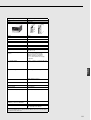
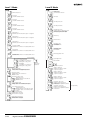
Contents
Temperature Controllers
Selection Guide
E5C2
I-2
Analogue Temperature Controller
E5@N
I-7
I-13
E5GN
Digital Temperature Controllers
I-15
E5CN
Digital Temperature Controllers
I-21
E5EN
Digital Temperature Controllers
I-29
E5AN
Digital Temperature Controllers
I-37
E5@N
Nomenclature, Installation, Operation
I-45
E5CK
Digital Controller
I-65
E5AK/E5EK
Digital Controller
I-87
E5@K-T
I-123
E5AK-T/E5EK-T
Digital Controller
I-125
E5CK-T
Digital Controller
I-127
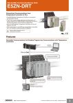
E5ZN
Modular Temperature Controller
I-129
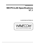
E5ZN-DRT
DeviceNet Communications Unit
I-145
I-151
E5AR
Digital Controllers
I-155
E5ER
Digital Controllers
I-169
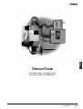
ThermoTools
I-207
Technical Information
I-213
Temperature
Controller
E5@R
I-1
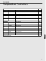
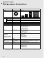
Selection Guide
Temperature Controllers
Model type
Analog Temperature Controller
Digital Temperature Controller
Model
E5C2
Basic
E5GN/E5CN/E5EN/E5AN
Standard type
Size (BxH) mm
48x48
E5GN: 24x48, E5CN: 48x48, E5EN: 48x96, E5AN: 96x96
Control
mode
ON/OFF
Yes
Yes
PID
Only P action
–
–
Yes
Position
proportional
–
–
Advanced
Function
Picture
2-PID
(see note)
–
–
Auto-tuning function
–
Yes
Self-tuning function
–
Yes
Hysteresis in ON/OFF control
action
0.5% FS fixed
0.1..999.9 EU (in units of 0.1 EU)
Indication accuracy
–
Thermocouple:
(±0.5% of indicated value or ±1°C,
whichever greater) ±1 digit max. (see note)
Platinum resistance thermometer:
(±0.5% of indicated value or ±1°C,
whichever greater) ±1 digit max.
Analog input: ±0.5% FS±1 digit max.
CT input: ±5% FS±1 digit max.
Input
K, L, JPt100, and THE
Thermocouple: K, J, T, E, L, U, N, R, S, B
Platinum resistance thermometer:
Pt100, JPt100
Non-contact temperature sensor:
10..70°C, 60..120°C, 115..165°C, 160..260°C
Voltage input: 0..50 mV linear
Output
Relay or Voltage output
Relay, voltage, and linear current output (E5GN: Relay, voltage)
Communication
–
RS485 (E5GN -FLK)
RS485 or Event IP (E5CN)
RS232, RS485 or Event IP
Heater burnout (not used with
current output)
–
Yes (E5AN, E5EN, E5CN)
Supply voltage
100/110/120, 200/220/240 VAC
at 50/60 Hz
100..240 VAC or 24 VAC/DC
Terminal configuration
Plug-in model
Screw terminals
EMC
Conforms to EN50081-2,
EN50082-2
Conforms to EN55011 Group 1 class A, EN55011 Group 1 class A, EN61000-4-2,
ENV50140, ENV50141, EN61000-4-4
Approved standards
UL (File No. E68481), CSA (File
No, LR59623), conforms to
EN61010-1
UL3121-1, CSA22.2 No. 14, E.B.1402C
Conforms to EN50081-2, EN50082-2, EN61010-1 (IEC61010-1) Conforms to
VDE0106/part 100 (Finger Protection), when the terminal cover is mounted.
Datasheet Cat. No.
H081
H107: E5AN/EN/CN/GN Datasheet
Manual Cat. No.
Page No.
Note
I-2
H100:
H101:
H111:
H112:
H102:
I-7
E5CN User's Manual
E5GN User's Manual
E5EN User's Manual
E5AN User's Manual
E5AN/EN/CN/GN
Communication Manual
I-13
This page provides information on main specifications only. Be sure to read the information on detailed specifications and precautions
before using the models listed here.
2-PID is Omron's advanced PID algorithm to achieve both good step- and disturbance response control
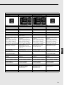
E5AK/E5EK
E5CK-T
Universal / Programmer type
E5EK-T/E5AK-T
48x48
E5AK: 96x96, E5EK: 48x96
E5AK-T: 96x96, E5EK-T: 48x96
48x48
Yes
Yes
Yes
Yes
–
–
–
–
Yes
Yes
Yes
Yes
–
–
–
–
–
Yes
Yes
–
Yes
Yes
Yes
Yes
Yes
Yes
Yes
Yes
0.01%..99.99% FS (in units of 0.01%)
0.01%..99.99% FS
(in units of 0.01%)
0.01%..99.99% FS (in units of 0.01%) 0.01%..99.99% FS (in units of 0.01%)
Thermocouple: (±0.3% of indicated
value or ±1°C, whichever greater)
±1 digit max.
Platinum resistance thermometer:
(±0.2% of indicated value or ±0.8°C,
whichever greater) ±1 digit max.
Analog input: ±0.2% FS ±1 digit max.
Thermocouple: (±0.3% of indicated value or ±1°C, whichever greater)
±1 digit max.
Platinum resistance thermometer:
(±0.2% of indicated value or ±0.8°C,
whichever greater) ±1 digit max.
Analog input: ±0.2% FS ±1 digit max.
Thermocouple: (±0.3% of indicated
value or ±1°C, whichever greater)
±1 digit max.
Platinum resistance thermometer:
(±0.2% of indicated value or ±0.8°C,
whichever greater) ±1 digit max.
Analog input: ±0.2% FS ±1 digit max.
Thermocouple: (±0.3% of indicated
value or ±1°C, whichever greater)
±1 digit max.
Platinum resistance thermometer:
(±0.2% of indicated value or ±0.8°C,
whichever greater) ±1 digit max.
Analog input: ±0.2% FS ±1 digit max.
K, J, T, L, U, N, R, S, B, W, PLII, JPt100,
or PT100
Linear current or voltage input
K, J, T, L, U, N, R, S, B, W, PLII, E
JPt100 or PT100
Linear current or voltage input
Pot.meter feedback / CT and remote
setvalue mA
K, J, T, L, U, N, R, S, B, W, PLII,
JPt100 or PT100
Linear current or voltage input
Pot.meter feedback / CT
K, J, T, L, U, N, R, S, B, W, PLII,
JPt100 or PT100
Linear current or voltage input
Relay, voltage, linear voltage, and
linear current output
Relay, SSR, voltage, linear voltage and
linear current ouput
Relay, SSR, voltage, linear voltage
and linear current ouput
Relay, voltage, linear voltage and linear
current output
RS232, RS485, Event IP or
Transfer OP
RS232, RS485, RS422, Event IP and
Transfer OP
RS232, RS485, RS422, Event IP and
Transfer OP
RS232, RS485, Event IP and
Transfer OP
Loop burnout alarm available
Yes
Yes
Loop burnout alarm available
100..240 VAC or 24 VAC/DC
at 50/60 Hz
100..240 VAC or 24 VAC/DC
at 50/60 Hz
100..240 VAC or 24 VAC/DC
at 50/60 Hz
100..240 VAC or 24 VAC/DC
at 50/60 Hz
Screw terminals
Screw terminals
Screw terminals
Screw terminals
Conforms to EN50081-2, EN50082-2
Conforms to EN50081-2, EN50082-2
Conforms to EN50081-2, EN50082-2
Conforms to EN50081-2, EN50082-2
UL (File No. E68481), CSA
(File No. LR59623),
conforms to EN61010-1
UL (File No. E68481),
CSA (File No. LR59623),
conforms to EN61010-1
UL (File No. E68481),
CSA (File No. LR59623),
conforms to EN61010-1
UL (File No. E68481),
CSA (File No. LR59623),
conforms to EN61010-1
H079: E5CK Digital Controller Cat.
H084: E5AK/EK Digital Controller DS
H087: E5@K-T Digital Controller DS
H087: E5@K-T Digital Controller DS
H078: E5CK User's Manual
H083: E5AK Users Manual
H085: E5EK Users Manual
H099: E5EK-DRT Manual
(Devicenet version)
H088: E5AK User's Manual
(Programmable Type)
H089: E5EK User's Manual
(Programmable Type)
H090: E5CK User's Manual
(Programmable Type)
I-65
I-87
I-125
I-127
I-3
Temperature
Controller
Digital Controller
E5CK
Universal type
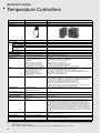
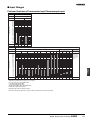
Selection Guide
Temperature Controllers
Model type
Modular Temperature Controller
Digital Process Controller
Model
E5ZN
In-panel type
E5ER/E5AR
Basic
Size (BxH) mm
22,5x130
E5ER: 48x96, E5AR; 96x96
Con- ON/OFF
trol
PID
mode
2-PID
(see note)
Yes
Yes
–
–
Yes
Yes
Position
proportional
–
Yes
Advanced
Function
Picture
–
Yes: Cascade, Ratio. Up to 4 loops in a single unit; 50ms sampling
Auto-tuning function
Yes
Yes
Self-tuning function
–
Yes
Hysteresis in ON/OFF
control action
0.1..999.9 EU (in units of 0.1 EU)
0.01 to 99.99% FS (units of 0.01% FS)
Indication accuracy
Thermocouple: (±0.5% of indicated value or ±1°C, whichever greater)
±1 digit max.
Platinum resistance thermometer:
(±0.5% of indicated value or ±1°C,
whichever greater) ±1 digit max.
Analog input: ±0.5% FS ±1 digit max.
Thermocouple input: (Larger of 0.1%PV and 1°C) 1 digit max.
[Not using internal cold contact compensation]
(Smaller of +0.1% FS and 1°C) 1 digit max.
Analog input: (0.1% FS) 1 digit max.
Platinum resistance temperature sensor input:
(Larger of 0.1% PV and 0.5°C) 1 digit max.
Position proportional potentiometer input: ( 5% FS) 1 digit max.
Input
Thermocouple: K, J, T, E, L, U, N, R, S, B
Non contact temperature sensor:
10..70°C, 60..120°C, 115..165°C,
160..260°C (ES1A series)
Voltage input: 0..50 mV linear
Platinum resistance thermometer:
Pt100, JPt100
Sensor input: Thermocouples: K, J, T, E, L, U, N, R, S, B, W
Platinum resistance temperature input sensors: Pt100
Current input: 4 to 20 mA DC, 0 to 20 mA DC (including remote SP input)
Voltage input: 1 to 5 V DC, 0 to 5 V DC, 0 to 10 V DC (including remote SP input)
(Input impedance: 150 using current
input, approx. 1 M using voltage input)
Output
Voltage, transistor or linear current output Voltage output: 12 V DC, 40 mA max, with short-circuit protection circuit
Current output: 0 to 20 mA DC/4 to 20 mA DC 500 load max. (including transfer output)
(Resolution: Approx. 54000 at 0 to 20 mA DC, approx. 43000 at 4 to 20 mA DC)
Relay output, Position proportional control type (open, close):
1a 250 V AC 1 A (including inrush current) (inductive load)
Auxiliary output: Relay output 1a 250 V AC 1 A (resistive load)
Transistor output: Maximum load voltage 30V DC, maximum load current 50 mA
Residual voltage 1.5 V max., leakage current 0.4 mA max.
Communication
RS485 and Event IP
Transfer OP on E5ZN-C....-types
E5ZN-DRT DeviceNet type
RS485: Compoway/F, Modbus; DeviceNet; Profibus via Gateway
Heater burnout (not used
with current output)
Yes
Yes
Supply voltage
24 VDC
100 to 240 V AC 50/60 Hz 24 V DC 50/60 Hz/24 V DC
Terminal configuration
Screw terminal
(Terminal Unit sold separately)
Screw terminals
EMC
EN61326
EMI: EN61326, Radiated Interference Electromagnetic Field Strength: EN55011 Group
1 class A, Noise Terminal Voltage:EN55011 Group 1 class A, EMS: EN61326, Immunity
ESD: EN61000-4-2: 4 kV contact discharge (level 2), 8 kV air discharge (level 3)
Immunity Electromagnetic:EN61000-4-3: 10 V/m (amplitude-modulated, 80 MHz to 1
GHz) (level 3), 10 V/m (pulse-modulated, 900 5 MHz) (level 3), Immunity Burst Noise:
EN61000-4-4: 2 kV power line (level 3), 2 kV measurement line, I/O signal line (level 4),
1 kV communications line (level 3), Immunity Conducted Disturbance: EN61000-4-6:
(0.15 to 80 MHz) (level 3), Immunity Surge: EN61000-4-5: 1 kV line to line (power line,
output line (relay output)) (level 2), 2 kV line to ground (power line, output line (relay output)) (level 3), Immunity Voltage Dip/Interrupting: EN61000-4-11: 0.5 cycle, 100% (rated
voltage)
Approved standards
UL, CSA
UL3121-1, CSA C22.2 No. 1010-1, EN61010-1 (IEC61010-1): Pollution
degree 2/overvoltage category 2
Datasheet Cat. No.
H116 and H120 (for E5ZN-DRT)
H122
Manual Cat. No.
H113
N182: user Manual,
H124: DeviceNet Communications Manual
Page No.
I-129
I-151
Note
I-4
This page provides information on main specifications only. Be sure to read the information on detailed specifications and precautions
before using the models listed here.
2-PID is Omron's advanced PID algorithm to achieve both good step- and disturbance response control
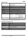
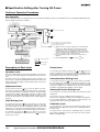
Multipoint Temperature Controller
E5CS-X
Basic
E5ZE
In-panel type
48x48
65x253
Yes
Yes
Yes
Yes
–
–
–
Yes
–
–
–
Yes
–
–
0.2% FS fixed
0.0..99.9°C/°F for ON/OFF control only (in
units of 0.1°C/°F)
+/-0.5% FS or +/-1°C (whichever
greater)
Thermocouple:
±0.3% or ±2°C of indicated value
(whichever is larger) ± 1 digit max.
Platinum resistance thermometer:
±0.3% or ±0.8°C (whichever is larger)
± 1 digit max.
K, J, JPt100, Pt100
K, J, R, S, T, E, B, N, L, U, W/Re5-26, PT II,
Pt100 or JPt100
Relay and Voltage
Linear voltage or current output
–
RS232, RS485, Devicenet
–
Yes
100..240VAC or 24VAC/DC
24 VDC
Screw terminals
Screw terminals
Conforms to EN50081-2, EN50082-2
Conforms to EN50081-2, EN50082-2
UL (File No. E68481), CSA (File No,
LR59623), conforms to EN61010-1
–
H032
H075 + H103 for E5ZE devicenet version
–
H104: E5ZE Communications Manual,
H076: E5ZE Operation Manual
Temperature
Controller
Digital Temperature Controller
This product is not shown in the catalogue.
For more information please contact your local Omron sales office or download the
data from www.eu.omron.com
I-5
Selection Guide
Temperature Controllers
I-6
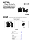
Analogue Temperature Controller
E5C2
DIN-sized (48 x 48 mm) Temperature
Controller with Analog Setting
• Compact, low-cost Temperature Controller.
• Incorporates proportional control and reset adjustment function.
• Consecutive mounting possible using mounting adapter.
• Incorporates a plug-in socket, thus allows to DIN-track and flush
mounting.
®
Model Number Structure
■ Model Number Legend
E5C2- @ @ @ @
1
2
3
4 5
4. Input type
K:
K-type thermocouple
L:
J-type thermocouple
P:
Platinum resistance thermometer (PT100)
G:
Thermistor (THE)
5. Special type
Blank: Standard type
D, DIN: Special types
Temperature
Controller
1. Model name
2. Control output
R:
Relay
Q:
Voltage
3. Control method
20: ON-OFF control
40: P control
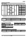
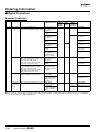
Ordering Information
■ Temperature Controllers
Setting
method
Indication
method
Control mode
Output
Model
Thermocouple
K (CA)
Chromel vs.
alumel
Analog setting No indication
L (IC)
Iron vs.
constantan
Platinum resistance
thermometer
Pt100
Thermistor
THE
ON/OFF
Relay
E5C2-R20K
E5C2-R20L-D E5C2-R20P-D
E5C2-R20G
P
Relay
E5C2-R40K
E5C2-R40L-D E5C2-R40P-D
---
Note: When placing an order, specify the standard temperature range and supply voltage in addition to the model number.
(e.g., E5C2-R20K 0°C to 200°C 100/110 VAC)
■ Accessories (Order Separately)
Name
Model
Front Connecting Socket
P2CF-08
Back Connecting Socket (for flush mounting)
P3G-08
Front Connecting Socket with Finger Protection
P2CF-08-E
Protective Cover (for finger protection)
Y92A-48G
Analogue Temperature Controller
E5C2
I-7
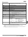
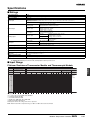
Specifications
■ Ratings
Supply voltage
100/110/120 VAC (common), 200/220/240 VAC (common) (See note.)
50/60 Hz (common)
Operating voltage range
90% to 110% of rated supply voltage
Power consumption
Approx. 2 VA
Input
Thermocouple (with sensor burnout detection circuit), platinum resistance thermometer, or thermistor
Control mode
ON/OFF or P control
Setting method
Analog setting
Indication method
No indication
Control output
Relay output: SPDT, 3 A at 250 VAC, resistive load (switching capacity: 330 VA)
Note: Specify either 100/110/120 VAC or 200/220/240 VAC when ordering.
■ Input Ranges
Input
Thermocouple
K (CA)
Chromel vs. alumel
Range
Platinum resistance
thermometer
Thermistor (see note 2)
Pt100
THE
L (IC)
Iron vs. constantan
°C
0 to 200 (5),
0 to 300 (10),
0 to 400 (10),
0 to 600 (20),
0 to 800 (20),
0 to 1,000 (25),
0 to 1,200 (25)
0 to 200 (5),
0 to 300 (10),
0 to 400 (10)
–50 to 50 (2),
–20 to 80 (2),
0 to 50 (1),
0 to 100 (2),
0 to 200 (5),
0 to 300 (10),
0 to 400 (10)
–50 to 50 (2) (6 kΩ at 0°C),
0 to 100 (2) (6 kΩ at 0°C),
50 to 150 (2) (30 kΩ at 0°C)
°F
32 to 392 (10),
32 to 572 (20),
32 to 752 (20),
32 to 1,112 (40),
32 to 1,472 (50),
32 to 1,832 (50),
32 to 2,192 (50)
32 to 392 (10),
32 to 572 (20),
32 to 752 (20)
32 to 212 (5),
32 to 392 (10)
---
Note: 1. Values in ( ) are the minimum unit.
2. Values in ( ) are the thermistor resistive value.
■ Characteristics
Setting accuracy
±2% FS max.
Hysteresis
Approx. 0.5% FS (fixed)
Proportional band
3% FS (fixed)
Control period
Approx. 20 s
Reset range (see note 1)
5 ±1% FS min.
Insulation resistance
20 MΩ min. (at 500 VDC)
Dielectric strength
2,000 VAC, 50/60 Hz for 1 min between charged terminals and uncharged metallic parts
Vibration resistance
Malfunction: 10 to 55 Hz, 0.15-mm single amplitude for 10 min each in X, Y, and Z directions
Destruction: 16.7 Hz, 2-mm double amplitude for 2 hrs each in X, Y, and Z directions
Shock resistance
Malfunction: 147 m/s2, 3 times each in 6 directions
Destruction: 294 m/s2, 3 times each in 6 directions
Life expectancy
Electrical:
Ambient temperature
Operating: –10°C to 55°C (with no icing or condensation)
Ambient humidity
Operating: 45% to 85%
Degree of protection
Front panel: IEC standard IP40 (see note 2)
Terminals: IEC standard IP00
Weight
Approx. 200 g (with flush-mounting adapter)
100,000 operations min. (3 A at 110 VAC, resistive load)
Note: 1. No reset function is incorporated by any E5C2 model with ON/OFF control.
2. The model number of the special watertight cover conforming to IP66, NEMA4 is Y92A-48B.
I-8
Analogue Temperature Controller E5C2
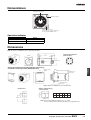
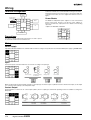
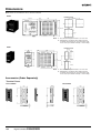
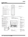
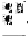
Nomenclature
Temperature setting knob
Operation indicator
RESET adjustment shaft
No reset function is incorporated by any
E5C2 model with ON/OFF control.
Operation Indicator
Indicator
Red
Output
Lit
ON
Not lit
OFF
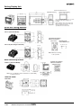
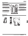
Dimensions
Note: All units are in millimeters unless otherwise indicated.
Terminal Arrangement
(Bottom View)
48 x 48
44.8 x 44.8
Flush-mounting
adapter
Temperature
Controller
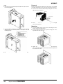
Dimensions with Flush-mounting Adapter (Accessory),
and Back Connecting Socket (Sold Separately)
Panel
Y92F-30 Flush-mounting adapter
P3G-08 Back connecting socket
Tightening screw
(96) (see note)
Note: 109 mm for US08 Back Connecting Socket
Panel Cutout
Side-by-side Mounting
of N Controllers
N
2
3
4
5
6
L
93+1
0
141+1
0
189+1
0
237+1
0
285+1
0
60 min.
Note: 1. Recommended panel thickness is 1 to 4 mm.
2. Close side-by-side mounting is possible (in a single direction).
Analogue Temperature Controller
E5C2
I-9
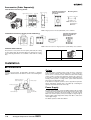
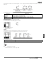
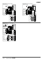
Accessories (Order Separately)
P2CF-08 Front Connecting Socket
Terminal Arrangement/
Internal Connections
(Top View)
Eight, M3.5 x 7.5 sems
Mounting Holes
Two, 4.5 dia. or Two, M4
70 max.
Two,
4.5-dia.
holes
Note: Can also be
mounted to a
DIN track.
50 max.
20 max.
Note: A finger-protection model (P2CF-08-E) is also available.
P3G-08 Back Connecting Socket (for Flush Mounting)
Terminal Arrangement/
Internal Connections
(Bottom View)
27 dia.
Note: A Protective Cover for finger protection (Y92A-48G) is also available.
Protective Cover Y92A-48
The protective cover protects the front panel, particularly the setting
section, against dust, dirt, and water drip. It also prevents the set values from being altered due to accidental contact with the setting
keys.
Appearance
Model
Y92A-48B
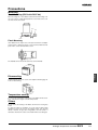
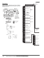
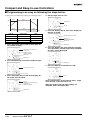
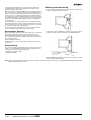
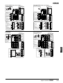
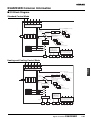
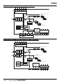
Installation
■ Connections
Input
Output
Connect a thermocouple, the E52-THE@ Thermistor or platinum
resistance thermometer to the E5C2 as shown in the following illustration.
If the load circuit is a heating control system, be sure to connect the
load to terminals 4 and 5. If the load circuit is a cooling control system, be sure to connect the load to terminals 4 and 6. If the heating
control system is connected to terminals 4 and 6 or the cooling control system is connected to terminals 4 and 5, the temperature of the
heating control system or cooling control system will be abnormal
and a serious accident may result.
Platinum resistance
thermometer input
Relay output
If the E5C2 is in frequent operation, such as proportional operation,
add an appropriate external relay to the E5C2 by considering the
capacity of the load and the life of the relay.
Thermocouple input
Power Supply
Thermistor input
Power supply
100/110, 200/220,
110/120, 220/240 VAC
50/60 Hz
If a single power supply is used for the E5C2 and the load, the supply
voltage of the power supply may vary greatly when the load is open
or closed if the capacity of the power supply is not large enough.
Make sure that the capacity of the power supply is large enough so
that the supply voltage range will be always from 90% to 110% of the
rated supply voltage.
The E5C2 operates at either 50 or 60 Hz.
I-10
Analogue Temperature Controller E5C2
Precautions
Mounting
Track Mounting (E5C2 with P2CF-08)
When mounting two or more E5C2 models with track-mounting sockets, leave a space of approximately 20 mm on both sides of the sockets where hooks are located.
Hook
Duct
P2CF-08
20
Panel
Flush Mounting
Insert E5C2 into the square hole of the panel and insert an adapter
from the back so that there will be no space between E5C2 and the
panel. Then, secure the E5C2 with a screw.
Tightening screw
Temperature
Controller
The P3G-08 can be wired in the same way as the P2CF-08.
Dismounting
If flush mounted, loosen the screw of the adapter and disengage the
hooks for dismounting.
Temperature Setting
Do not turn the temperature setting knob of the E5C2 with excessive
force, otherwise the stopper of the knob may break.
Others
Do not remove the housing of the E5C2, otherwise the housing may
break.
To clean the surface of the E5C2, use a soft cloth wet with neutral
detergent or alcohol. Do not use any organic solvent, such as paint
thinner or benzine, strong acid or strong alkali to clean the surface of
the E5C2, otherwise the surface of the E5C2 will become damaged.
Analogue Temperature Controller
E5C2
I-11
ALL DIMENSIONS SHOWN ARE IN MILLIMETERS.
To convert millimeters into inches, multiply by 0.03937. To convert grams into ounces, multiply by 0.03527.
Cat. No. H081-E1-02
I-12
In the interest of product improvement, specifications are subject to change without notice.
Analogue Temperature Controller E5C2
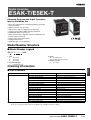
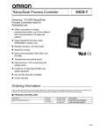
Digital Temperature Controllers
E5@N
Compact and Intelligent
General-purpose Temperature
Controllers
• Various temperature inputs: thermocouple, platinum
resistance thermometer, infrared temperature sensor,
and analog inputs.
• Auto-tuning and self-tuning available. Auto-tuning is
possible even while self-tuning is being executed.
• Heating or heating/cooling control is available.
• Event input allows multiple SP selection and run/stop
function.
• Water-resistant construction (NEMA4X: equivalent to
IP66).
• Conforms to UL, CSA, and IEC safety standards as
well as CE marking.
E5AN
1/4 DIN
E5EN
E5CN
E5GN
1/8 DIN
1/16 DIN
1/32 DIN
Temperature
Controller
E5@N Series
Contents
Digital Temperature Controllers
E5GN............................................................
I-15
E5CN............................................................
I-21
E5EN ............................................................
I-29
E5AN ............................................................
I-37
Common to All Controllers
•
•
•
•
•
Nomenclature ...............................................
Installation ....................................................
Operation......................................................
Peripheral Devices .......................................
Precautions ..................................................
I-45
I-47
I-50
I-60
I-62
Digital Temperature Controllers
E5@N
I-13
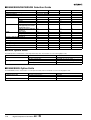
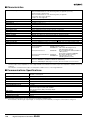
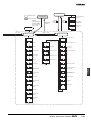
■ E5AN/E5EN/E5CN/E5GN Selection Guide
Item
E5AN
E5EN
Dimensions (W x H x D (mm))
96 x 96 x 78
Indication accuracy
±0.5% PV±1 digit max.
Control method
48 x 96 x 78
E5CN
E5GN
48 x 48 x 78
48 x 24 x 100
2-PID or ON/OFF
Alarm
Input
Output
None
No
No
Yes
Yes
1 point
No
No
No
Yes
2 points
No
No
Yes
No
3 points
Yes
Yes
No
No
Thermocouple input
Analog input by non-contact
temperature sensor
Yes
Yes
Yes
Yes
Platinum resistance temperature sensor
Yes
Yes
Yes
Yes
Relay output
Yes
Yes
Yes
Yes
Voltage output
Yes
Yes
Yes
Yes
Current output
Yes
Yes
Yes
No
RS-232C communication function
Yes
Yes
No
No
RS-485 communication function
Yes
Yes
Yes
Yes
Event input
Yes
Yes
Yes
No
Heater burnout alarm
Yes
Yes
Yes
No
Heating/Cooling control
Yes
Yes
Yes
Yes
Run/Stop
Yes
Yes
Yes
Yes
Multiple SP selection
Yes
Yes
Yes
Yes
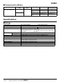
■ E5CN Option Units
The E5CN provides communication or event input functionality when mounted with one of the following Option Units.
Name
Communications Unit
Event Input Unit
Function
Model
RS-485 communication and heater burnout alarm
E53-CNH03 (For relay and voltage output)
RS-485 communication
E53-CN03 (For current output)
Event input and heater burnout alarm
E53-CNHB (For relay and voltage output)
Event input
E53-CNB (For current output)
Note: The heater burnout alarm is available by mounting the E53-CNH03 or E53-CNHB Option Unit on E5CN.
■ E5AN/E5EN Option Units
The E5AN/E5EN provides communication or event input functionality when mounted with one of the following Option Units.
Name
Communications Unit
Event Input Unit
I-14
Function
Model
RS-232C communication
E53-AK01
RS-485 communication
E53-AK03
Event input
E53-AKB
Digital Temperature Controllers E5
@N
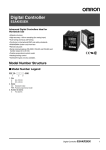
Digital Temperature Controllers
E5GN
Compact and Intelligent Temperature
Controllers
1/32 DIN with Communications Function
• Various temperature inputs: Thermocouple, platinum resistance
thermometer, infrared temperature sensor, and analog inputs.
• Auto-tuning and self-tuning available. Auto-tuning is possible
even while self-tuning is being executed.
• Heating or heating/cooling control is available.
• Water-resistant construction (NEMA4X: equivalent to IP66).
• Conforms to UL, CSA, and IEC safety standards as well as CE
marking.
48(W) x 24(H) x 100(D) mm
Model Number Structure
■ Model Number Legend
E5GN- @ @ @ @ -FLK
1
2
3
4
5
4. Input type
TC: Thermocouple
P:
Platinum resistance thermometer
5. CompoWay/F serial communications
-FLK: CompoWay/F serial communications
Temperature
Controller
1. Output type
R:
Relay
Q:
Voltage (for driving SSR)
2. Number of alarms
Blank:No alarm
1:
One alarm
3. Communications
Blank:No communications function
03: RS-485
Ordering Information
■ Standard Models
Size
1/32 DIN
48(W) x 24(H) x 100(D) mm
Power supply
voltage
100 to 240 VAC
No. of alarm
points
---
1
(see note 1)
24 VAC/VDC
---
1
(see note 1)
Control output
Thermocouple
model
Platinum resistance
thermometer model
Relay
E5GN-RTC
E5GN-RP
Voltage (for driving
SSR)
E5GN-QTC
E5GN-QP
Relay
E5GN-R1TC
E5GN-R1P
Voltage (for driving
SSR)
E5GN-Q1TC
E5GN-Q1P
Relay
E5GN-RTC
E5GN-RP
Voltage (for driving
SSR)
E5GN-QTC
E5GN-QP
Relay
E5GN-R1TC
E5GN-R1P
Voltage (for driving
SSR)
E5GN-Q1TC
E5GN-Q1P
Note 1. If the heating/cooling function is used, ALM1 will be used for control output and so alarm output will not be available.
2. Control output 2 for heating/cooling control is relay output.
3. Specify the power supply specifications when ordering.
Digital Temperature Controllers
E5GN
I-15
■ Communication Models
Size
Power supply
voltage
1/32 DIN
48(W) x 24(H) x 100(D) mm
100 to 240 VAC
Communication
function
RS-485
24 VAC/VDC
Control output
Thermocouple model Platinum resistance
thermometer model
Relay
E5GN-R03TC-FLK
E5GN-R03P-FLK
Voltage (for driving
SSR)
E5GN-Q03TC-FLK
E5GN-Q03P-FLK
Relay
E5GN-R03TC-FLK
E5GN-R03P-FLK
Voltage (for driving
SSR)
E5GN-Q03TC-FLK
E5GN-Q03P-FLK
Note: Specify the power supply specifications when ordering.
Specifications
■ Ratings
Supply voltage
100 to 240 VAC, 50/60 Hz
Operating voltage range
85% to 110% of rated supply voltage
Power consumption
7 VA
Sensor input
Thermocouple:
Platinum resistance thermometer:
Infrared temperature sensor:
Voltage input:
Control output
Relay output
Voltage output
24 VAC, 50/60 Hz/24 VDC
4 VA/2.5 W
K, J, T, E, L, U, N, R, S, B
Pt100, JPt100
10 to 70°C, 60 to 120°C, 115 to 165°C, 160 to 260°C
0 to 50 mV
SPST-NO, 250 VAC, 2 A (resistive load), electrical life: 100,000 operations
12 VDC (PNP), max. load current: 21 mA, with short-circuit protection circuit
Alarm output
SPST-NO, 250 VAC, 1 A (resistive load), electrical life: 100,000 operations
Control method
2-PID or ON/OFF control
Setting method
Digital setting using front panel keys
Indication method
7-segment digital display and single-lighting indicator
Character height: PV: 7.0 mm; SV: 3.5 mm
Other functions
According to controller model
Ambient temperature
−10 to 55°C (with no condensation or icing)
Ambient humidity
25% to 85%
Storage temperature
−25 to 65°C (with no condensation or icing)
I-16
Digital Temperature Controllers E5GN
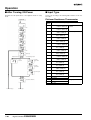
■ Input Ranges
Platinum Resistance Thermometer Input/Thermocouple Input
Platinum resistance thermometer input
Input type
Platinum resistance thermometer
Temperature range
Name
1800
1700
1600
1500
1400
1300
1200
1100
1000
900
800
700
600
500
400
300
200
100
0
−100
−200
Set value
Pt100
JPt100
850
500.0
−200
−199.9
0
1
500.0
100.0
100.0
0.0
0.0
−199.9
2
3
4
Thermocouple input
Input type
Set value
K
J
T
E
L
U
N
R
S
B
K10 to
70°C
K60 to
120°C
Analog input
K115 to K160 to
165°5C 260°C
1800
1700
Usable in the
following ranges by scaling:
−1999 to 9999
or −199.9 to
999.9
1700
1300
1300
850
0 to 50 mV
850
600
500.0
400.0
400
400.0
400
Temperature
Controller
Temperature range
Name
1800
1700
1600
1500
1400
1300
1200
1100
1000
900
800
700
600
500
400
300
200
100
0
−100
−200
ES1A Infrared
Temperature Sensor
Thermocouple
400.0
260
120
165
0
0
0
0
12
13
14
15
70
100
−20.0
−20.0
0
−100
1
2
0
9
10
−100
−200
0
0
3
−200
−199.9
4
17
5
6
−200
−199.9
−200
7
18
8
11
16
Applicable standards by input type are as follows:
K, J, T, E, N, R, S, B: JIS C1602-1995
L: Fe-CuNi, DIN 43710-1985
U: Cu-CuNi, DIN 43710-1985
JPt100: JIS C1604-1989, JIS C1606-1989
Pt100: JIS C1604-1997, IEC751
Shaded ranges indicate default settings.
ES1A models with a temperature range of 160°C to 260°C have been discontinued.
Digital Temperature Controllers
E5GN
I-17
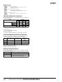
■ Characteristics
Indication accuracy
Thermocouple:
(±0.5% of indicated value or ±1°C, whichever greater) ±1 digit max. (see note)
Platinum resistance thermometer:
(±0.5% of indicated value or ±1°C, whichever greater) ±1 digit max.
Analog input: ±0.5% FS±1 digit max.
CT input: ±5% FS±1 digit max.
Hysteresis
0.1 to 999.9 EU (in units of 0.1 EU)
Proportional band (P)
0.1 to 999.9 EU (in units of 0.1 EU)
Integral time (I)
0 to 3999 s (in units of 1 s)
Derivative time (D)
0 to 3999 s (in units of 1 s)
Control period
1 to 99 s (in units of 1 s)
Manual reset value
0.0% to 100.0% (in units of 0.1%)
Alarm setting range
−1999 to 9999 (decimal point position depends on input type)
Sampling period
500 ms
Insulation resistance
20 MΩ min. (at 500 VDC megger)
Dielectric strength
2000 VAC, 50 or 60 Hz for 1 min (between different charging terminals)
Vibration resistance
10 to 55 Hz, 10 m/s2 for 2 hours each in X, Y and Z directions
Shock resistance
300 m/s2, 3 times each in 3 axes, 6 directions (relay: 100 m/s2)
Weight
Approx. 90 g
Degree of protection
Front panel: NEMA4X for indoor use (equivalent to IP66), rear case: IP20, terminals: IP00
Memory protection
EEPROM (non-volatile memory) (number of writes: 100,000)
EMC
Emission Enclosure:
Emission AC Mains:
Immunity ESD:
Approved standards
UL3121-1, CSA22.2 No. 142, E.B.1402C
Conforms to EN50081-2, EN50082-2, EN61010-1 (IEC61010-1)
Conforms to VDE0106/part 100 (Finger Protection), when the terminal cover is mounted.
Mounting bracket: approx. 10 g
EN55011 Group 1 class A
EN55011 Group 1 class A
EN61000-4-2: 4 kV contact discharge (level 2)
8 kV air discharge (level 3)
Immunity RF-interference:
ENV50140:
10 V/m (amplitude modulated, 80 MHz to
1 GHz) (level 3)
10 V/m (pulse modulated, 900 MHz)
Immunity Conducted Disturbance: ENV50141:
10 V (0.15 to 80 MHz) (level 3)
Immunity Burst:
EN61000-4-4: 2 kV power-line (level 3)
2 kV I/O signal-line (level 4)
Note: The indication of K thermocouples in the −200 to 1300°C range, and T and N thermocouples at a temperature of −100°C or less, and U and
L thermocouples at any temperature is ±2°C±1 digit maximum. The indication of B thermocouples at a temperature of 400°C or less is unrestricted.
The indication of R and S thermocouples at a temperature of 200°C or less is ±3°C±1 digit maximum.
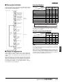
■ Communications Specifications
Transmission path connection
Multiple points
Communications method
RS-485 (two-wire, half duplex)
Synchronization method
Start-stop synchronization
Baud rate
1,200/2,400/4,800/9,600/19,200 bps
Transmission code
ASCII
Data bit length (see note)
7 or 8 bits
Stop bit length (see note)
1 or 2 bits
Error detection
Vertical parity (none, even, odd)
Frame check sequence (FCS): with SYSWAY
Block check character (BCC): with CompoWay/F
Flow control
Not available
Interface (see note)
RS-485
Retry function
Not available
Communications buffer
40 bytes
Note: The baud rate, data bit length, stop bit length, or vertical parity can be individually set using the communications setting level.
I-18
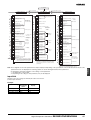
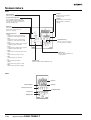
Digital Temperature Controllers E5GN
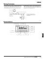
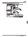
Wiring Terminals
• The voltage output (control output) is not electrically insulated from
the internal circuits. When using a grounding thermocouple, do not
connect the control output terminals to the ground. If the control
output terminals are connected to the ground, errors will occur in
the measured temperature values as a result of leakage current.
• Standard insulation is applied to the power supply I/O sections. If
reinforced insulation is required, connect the input and output terminals to a device without any exposed current-carrying parts or to
a device with standard insulation suitable for the maximum operating voltage of the power supply I/O section.
Control output
Relay output
Voltage output
12 VDC
21 mA
Alarm output/control output 2/input error output
Two input power supplies are available:
100 to 240 VAC or 24 VAC/VDC (no polarity).
Recommended power supply for 24VDC;
eg. OMRON S8VS.
Input power supply
Analog input
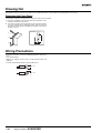
Nomenclature
Temperature unit
No.1 display
CMW
STP
OUT
Operation
indicators
No.2 display
Level key
Mode key
Temperature
Controller
Up key
Down key
Digital Temperature Controllers
E5GN
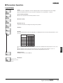
I-19
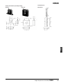
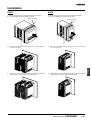
Dimensions
Note: All units are in millimeters unless otherwise indicated.
48
35
3
24
100
22
(36.8)
44.8
*When carrying out maintenance on the E5GN, only the terminal plate
can be drawn out with the terminal leads still attached.
22
Panel Cutout
Mounted Separately
Group Mounted
+1.0
(48 × number of units -2.5) 0
+0.3
22 0
Mounting separately does not allow waterproofing.
40 min.
+0.6
45 0
+0.3
22 0
• Insert the Controller through the hole in the panel from the front and push
the adapter on from the rear. Push the adapter up to the back of the panel
ensuring that the controller is pushed all the way in, removing any gap
between the Controller, panel, and adapter. Finally, use the two screws on
the adapter to secure the unit in place.
• To mount the E5GN so that it is waterproof, insert the waterproof packing
onto the E5GN.
• When two or more E5GN Controllers are mounted, make sure that the
surrounding temperature does not exceed the allowable operating
temperature given in the specifications.
ALL DIMENSIONS SHOWN ARE IN MILLIMETERS.
To convert millimeters into inches, multiply by 0.03937. To convert grams into ounces, multiply by 0.03527.
I-20
Digital Temperature Controllers E5GN
Digital Temperature Controllers
E5CN
Compact and Intelligent Temperature
Controllers
• Various temperature inputs: thermocouple, platinum resistance
thermometer, infrared temperature sensor, and analog inputs.
• Auto-tuning and self-tuning available. Auto-tuning is possible
even while self-tuning is being executed.
• Heating or heating/cooling control is available.
• Event input allows multiple SP selection and run/stop function.
• The PV display color can be changed according to the application (red or green).
• Water-resistant construction (NEMA4X: equivalent to IP66).
• Conforms to UL, CSA, and IEC safety standards as well as CE
marking.
48(W) x 48(H) x 78(D) mm
Model Number Structure
■ Model Number Legend
E5CN- @ @ M @ -500
2
3
4
3. Option Unit
M:
Option Unit can be mounted
4. Input type
TC: Thermocouple
P:
Platinum resistance thermometer
1. Output type
R:
Relay
Q:
Voltage (for driving SSR)
C:
Current
2. Number of alarms
Blank:No alarm
2:
Two alarms
Note: An Option Unit is required to use heater burnout alarm.
Ordering Information
■ Standard Models
Size
1/16 DIN
48(W) x 48(H) x 78(D) mm
Power supply
voltage
100 to 240 VAC
No. of
alarm
points
---
2
24 VAC/VDC
---
2
Control output
Thermocouple
model
Platinum
resistance
thermometer
model
Relay
E5CN-RMTC-500
E5CN-RMP-500
Voltage (for driving SSR)
E5CN-QMTC-500
E5CN-QMP-500
Current
E5CN-CMTC-500
E5CN-CMP-500
Relay
E5CN-R2MTC-500
E5CN-R2MP-500
Voltage (for driving SSR)
E5CN-Q2MTC-500
E5CN-Q2MP-500
Current
E5CN-C2MTC-500
E5CN-C2MP-500
Relay
E5CN-RMTC-500
E5CN-RMP-500
Voltage (for driving SSR)
E5CN-QMTC-500
E5CN-QMP-500
Current
E5CN-CMTC-500
E5CN-CMP-500
Relay
E5CN-R2MTC-500
E5CN-R2MP-500
Voltage (for driving SSR)
E5CN-Q2MTC-500
E5CN-Q2MP-500
Current
E5CN-C2MTC-500
E5CN-C2MP-500
Note 1. A Current Transformer (CT) is not provided with the Unit. Be sure to order one when ordering the E5CN.
2. The heating and cooling function is available for models with two alarm points.
3. Specify the power supply specifications when ordering.
Digital Temperature Controllers E5CN
I-21
Temperature
Controller
1
■ Option Units
The E5CN provides communications or event input functionality when mounted with one of the following Option Units.
Name
Model
Function
Communications Unit
E53-CNH03 (For relay and voltage output)
RS-485 communication and heater burnout alarm
E53-CN03 (For current output)
RS-485 communication
Event Input Unit
E53-CNHB (For relay and voltage output)
Event input and heater burnout alarm
E53-CNB (For current output)
Event input
Note: The heater burnout alarm is available by mounting the E53-CNH03 or E53-CNHB Option Unit on the E5CN.
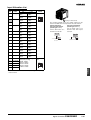
■ Current Transformer (Sold
Separately)
■ Terminal Cover
Model
E54-CT1
E54-CT3
Hole diameter
5.8 dia.
12.0 dia.
Note: The Terminal Cover comes with the E5CN and does not have
to be purchased separately.
Model
E53-COV10
Specifications
■ Ratings
Supply voltage
100 to 240 VAC, 50/60 Hz
Operating voltage range
85% to 110% of rated supply voltage
Power consumption
7 VA
Sensor input
Thermocouple:
Platinum resistance thermometer:
Infrared temperature sensor:
Voltage input:
Control output
24 VAC, 50/60 Hz/24 VDC
4 VA/3 W
K, J, T, E, L, U, N, R, S, B
Pt100, JPt100
10 to 70°C, 60 to 120°C, 115 to 165°C, 160 to 260°C
0 to 50 mV
Relay output
SPST-NO, 250 VAC, 3 A (resistive load), electrical life: 100,000 operations
Voltage output
12 VDC (PNP), max. load current: 21 mA, with short-circuit protection circuit
Current output
4 to 20 mA DC, load: 600 Ω max., resolution: approx. 2,600
Alarm output
SPST-NO, 250 VAC, 1 A (resistive load), electrical life: 100,000 operations
Control method
2-PID or ON/OFF control
Setting method
Digital setting using front panel keys
Indication method
7-segment digital display and single-lighting indicator
Character height: PV: 9.9 mm; SV: 6.4 mm
Other functions
According to Controller model
Ambient temperature
−10 to 55°C (with no condensation or icing)
Ambient humidity
25% to 85%
Storage temperature
−25 to 65°C (with no condensation or icing)
I-22
Digital Temperature Controllers E5CN
■ Input Ranges
Platinum Resistance Thermometer Input/Thermocouple Input
Platinum resistance thermometer input
Input type
Platinum resistance thermometer
Temperature range
Name
1800
1700
1600
1500
1400
1300
1200
1100
1000
900
800
700
600
500
400
300
200
100
0
−100
−200
Set value
Pt100
JPt100
850
500.0
−200
−199.9
0
1
500.0
100.0
100.0
0.0
0.0
−199.9
2
3
4
Thermocouple input
Input type
K
Set value
J
T
E
L
U
N
R
S
B
K10 to
70°C
Analog input
K60 to K115 to K160 to
120°C 165°C 260°C
1800
1700
1300
Usable in the
following ranges by scaling:
−1999 to 9999
or −199.9 to
999.9
1700
1300
850
0 to 50 mV
850
600
Temperature
Controller
Temperature range
Name
1800
1700
1600
1500
1400
1300
1200
1100
1000
900
800
700
600
500
400
300
200
100
0
−100
−200
ES1A Infrared
Temperature Sensor
Thermocouple
500.0
400.0
400
400.0
400
400.0
260
120
165
0
0
0
0
12
13
14
15
70
100
−20.0
−20.0
0
−100
0
1
2
0
0
9
10
−100
−200
−200
3
4
−199.9
17
5
6
−200
−199.9
−200
7
18
8
11
16
Applicable standards by input type are as follows:
K, J, T, E, N, R, S, B: JIS C1602-1995
L: Fe-CuNi, DIN 43710-1985
U: Cu-CuNi, DIN 43710-1985
JPt100: JIS C1604-1989, JIS C1606-1989
Pt100: JIS C1604-1997, IEC751
Shaded ranges indicate default settings.
ES1A models with a temperature range of 160°C to 260°C have been discontinued.
Digital Temperature Controllers E5CN
I-23
■ Characteristics
Indication accuracy
Thermocouple:
(±0.5% of indicated value or ±1°C, whichever greater) ±1 digit max. (see note)
Platinum resistance thermometer:
(±0.5% of indicated value or ±1°C, whichever greater) ±1 digit max.
Analog input: ±0.5% FS±1 digit max.
CT input: ±5% FS±1 digit max.
Hysteresis
0.1 to 999.9 EU (in units of 0.1 EU)
Proportional band (P)
0.1 to 999.9 EU (in units of 0.1 EU)
Integral time (I)
0 to 3999 s (in units of 1 s)
Derivative time (D)
0 to 3999 s (in units of 1 s)
Control period
1 to 99 s (in units of 1 s)
Manual reset value
0.0% to 100.0% (in units of 0.1%)
Alarm setting range
−1999 to 9999 (decimal point position depends on input type)
Sampling period
500 ms
Insulation resistance
20 MΩ min. (at 500 VDC)
Dielectric strength
2000 VAC, 50 or 60 Hz for 1min (between different charging terminals)
Vibration resistance
10 to 55 Hz, 10 m/s2 for 2 hours each in X, Y and Z directions
Shock resistance
300 m/s2, 3 times each in 3 axes, 6 directions (relay: 100 m/s2)
Weight
Approx. 150 g
Degree of protection
Front panel: NEMA4X for indoor use (equivalent to IP66), rear case: IP20, terminals: IP00
Memory protection
EEPROM (non-volatile memory) (number of writes: 100,000)
EMC
Emission Enclosure:
Emission AC Mains:
Immunity ESD:
Approved standards
UL3121-1, CSA22.2 No. 142, E.B.1402C
Conforms to EN50081-2, EN50082-2, EN61010-1 (IEC61010-1)
Conforms to VDE0106/part 100 (Finger Protection), when the terminal cover is mounted.
Mounting bracket: Approx. 10 g
EN55011 Group 1 class A
EN55011 Group 1 class A
EN61000-4-2: 4 kV contact discharge (level 2)
8 kV air discharge (level 3)
Immunity RF-interference:
ENV50140: 10 V/m (amplitude modulated, 80 MHz to
1 GHz) (level 3)
10 V/m (pulse modulated, 900 MHz)
Immunity Conducted Disturbance: ENV50141: 10 V (0.15 to 80 MHz) (level 3)
Immunity Burst:
EN61000-4-4: 2 kV power-line (level 3)
2 kV I/O signal-line (level 4)
Note: The indication of K thermocouples in the −200 to 1300°C range, and T and N thermocouples at a temperature of −100°C or less, and U and
L thermocouples at any temperature is ±2°C±1 digit maximum. The indication of B thermocouples at a temperature of 400°C or less is unrestricted.
The indication of R and S thermocouples at a temperature of 200°C or less is ±3°C±1 digit maximum.
■ Communications Specifications
Transmission path connection
Multiple points
Communications method
RS-485 (two-wire, half duplex)
Synchronization method
Start-stop synchronization
Baud rate
1,200/2,400/4,800/9,600/19,200 bps
Transmission code
ASCII
Data bit length (see note)
7 or 8 bits
Stop bit length (see note)
1 or 2 bits
Error detection
Vertical parity (none, even, odd)
Frame check sequence (FCS): with SYSWAY
Block check character (BCC): with CompoWay/F
Flow control
Not available
Interface (see note)
RS-485
Retry function
Not available
Communications buffer
40 bytes
Note: The baud rate, data bit length, stop bit length, or vertical parity can be individually set using the communications setting level.
I-24
Digital Temperature Controllers E5CN
■ Current Transformer (Sold Separately) Ratings
Dielectric strength
1,000 VAC (1 min)
Vibration resistance
50 Hz 98 m/s2
Weight
E54-CT1: Approx. 11.5 g
E54-CT3: Approx. 50 g
Accessories (E54-CT3 only)
Armature (2)
Plug (2)
■ Heater Burnout Alarm Specifications
Max. heater current
Single-phase AC: 50 A (see note 1)
Input current readout accuracy
±5%FS±1 digit max.
Heater burnout alarm setting range
0.0 to 50.0 A (0.1 A units) (see note 2)
Min. detection ON time
190 ms (see note 3)
Note 1. When heater burnout is detected on a 3-phase heater, use the K2CU-F@@A-@GS (with gate input terminal).
2. When the set value is “00 A,” the heater burnout alarm will always be OFF. When the set value is “50.0 A,” the heater burnout alarm will
always be ON.
3. When the control output ON time is less than 190 ms, heater burnout detection and heater current measurement will not be carried out.
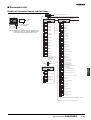
Wiring Terminals
• The voltage output (control output) is not electrically insulated from
the internal circuits. When using a grounding thermocouple, do not
connect the control output terminals to the ground. If the control
output terminals are connected to the ground, errors will occur in
the measured temperature values as a result of leakage current.
Current output
4 DC to 20 mA
Control output 1
Voltage Output
• Standard insulation is applied to the power supply I/O sections. If
reinforced insulation is required, connect the input and output terminals to a device without any exposed current-carrying parts or to
a device with standard insulation suitable for the maximum operating voltage of the power supply I/O section.
Alarm output
Relay Output
12 VDC
21 mA
ALM2/Control
output 2
Input power supply
Temperature
Controller
Analog input
ALM1/Heater
burnout
Two input power supplies are available: 100 to 240 VAC or 24 VDC.
Recommended power supply for 24VDC; eg. OMRON S8VS.
■ Option Units
E53-CNHB Event Input/Heater
Burnout Alarm Unit
Event Input/Heater Burnout Detection
Contact input
Non-contact input
Heater burnout detection input
E53-CNB Event Input
Event Input
Contact input
Non-contact input
Do not connect anything.
Do not connect anything.
Digital Temperature Controllers E5CN
I-25
E53-CNH03 Communications/Heater
Burnout Alarm Unit
E53-CN03 Communications Unit
Host computer
Communications Specification
Host computer
Communications Specification/Heater Burnout Specification
Do not connect anything.
Do not connect anything.
Do not connect anything.
Do not connect anything.
Nomenclature
Temperature
unit
No.1 display
Operation
indicators
No.2 display
Up key
Level key
Mode key
Down key
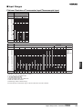
Dimensions
Note: All units are in millimeters unless otherwise indicated.
Panel Cutouts
Mounted Separately
60 min.
Group Mounted
+1.0
(48 × number of units -2.5) 0
45 +0.6
0
60 min.
45 +0.6
0
Group mounting does
not allow waterproofing.
45
+0.6
0
44.8 x 44.8
48 x 48
Note:
The suffix "500" is added to the model number of each
Controller provided with a E53-COV10 Terminal Cover.
I-26
Digital Temperature Controllers E5CN
• Recommended panel thickness is 1 to 5 mm.
• Group mounting is not possible in the vertical direction.
(Maintain the specified mounting space between Controllers
when they are group mounted.)
• To mount the E5CN so that it is waterproof, apply the waterproof
packing to the E5CN.
• When two or more E5CNs are mounted, make sure that the
surrounding temperature does not exceed the allowable
operating temperature specified in the specifications.
Terminal Cover
E53-COV10
Current Transformer (Sold Separately)
E54-CT1
E54-CT3
2.36 dia.
5.8 dia.
12 dia.
40 x 40
Two, M3 (depth: 4)
Temperature
Controller
Two, 3.5 dia.
Digital Temperature Controllers E5CN
I-27
ALL DIMENSIONS SHOWN ARE IN MILLIMETERS.
To convert millimeters into inches, multiply by 0.03937. To convert grams into ounces, multiply by 0.03527.
I-28
Digital Temperature Controllers E5CN
Digital Temperature Controllers
E5EN
Compact and Intelligent Temperature
Controllers
• Depth of only 78 mm.
• Various temperature inputs: thermocouple, platinum resistance
thermometer, infrared temperature sensor, and analog inputs.
• Auto-tuning and self-tuning available. Auto-tuning is possible
even while self-tuning is being executed.
• Heating or heating/cooling control is available.
• Event input allows multiple SP selection and run/stop function.
• Water-resistant construction (NEMA4X: equivalent to IP66).
• Conforms to UL, CSA, and IEC safety standards as well as CE
marking.
48(W) x 96(H) x 78(D) mm
Model Number Structure
■ Model Number Legend
E5EN- @ @ @ M @ -500
1
2
3
4
5
4. Option Unit
M:
Option Unit can be mounted
5. Input type
TC: Thermocouple
P:
Platinum resistance thermometer
Temperature
Controller
1. Output type
R:
Relay
Q:
Voltage (for driving SSR)
C:
Current
2. Number of alarm
3:
Three alarms
3. Heater burnout alarm
Blank:Not available
H:
Available
Ordering Information
■ Standard Models
Size
1/8 DIN
48(W) x 96(H) x
78(D) mm
Power supply
voltage
100 to 240 VAC
No. of alarm
points
3
Control output
Relay
Voltage
(for driving SSR)
24 VAC/VDC
3
Heater burnout
alarm
Thermocouple model Platinum resistance
thermometer model
No
E5EN-R3MTC-500
E5EN-R3MP-500
Yes
E5EN-R3HMTC-500
E5EN-R3HMP-500
No
E5EN-Q3MTC-500
E5EN-Q3MP-500
Yes
E5EN-Q3HMTC-500
E5EN-Q3HMP-500
Current
No
E5EN-C3MTC-500
E5EN-C3MP-500
Relay
No
E5EN-R3MTC-500
E5EN-R3MP-500
Yes
E5EN-R3HMTC-500
E5EN-R3HMP-500
Voltage
(for driving SSR)
No
E5EN-Q3MTC-500
E5EN-Q3MP-500
Yes
E5EN-Q3HMTC-500
E5EN-Q3HMP-500
Current
No
E5EN-C3MTC-500
E5EN-C3MP-500
Note 1. A Current Transformer (CT) is not provided with the Unit. Be sure to order one when ordering the E5EN.
2. When the heating and cooling function or the heater burnout alarm is used, one of the alarm outputs will be disabled for each function used.
3. Specify the power supply specifications when ordering.
Digital Temperature Controllers
E5EN
I-29
■ Option Units
The E5EN provides communication or event input functionality when
mounted with one of the following Option Units.
Name
Communication Unit
Event Input Unit
Model
Function
E53-AK01
RS-232C communication
E53-AK03
RS-485 communication
E53-AKB
Event input
■ Current Transformer (Sold
Separately)
Model
E54-CT1
E54-CT3
Hole diameter
5.8 dia.
12.0 dia.
■ Terminal Cover
Model
E53-COV11
Note: The Terminal Cover comes with the E5EN and does not have
to be purchased separately.
Specifications
■ Ratings
Supply voltage
100 to 240 VAC, 50/60 Hz
Operating voltage range
85% to 110% of rated supply voltage
Power consumption
9 VA
Sensor input
Thermocouple:
Platinum resistance thermometer:
Infrared temperature sensor:
Voltage input:
Control output
24 VAC, 50/60 Hz/24 VDC
5 VA/4 W
K, J, T, E, L, U, N, R, S, B
Pt100, JPt100
10 to 70°C, 60 to 120°C, 115 to 165°C, 160 to 260°C
0 to 50 mV
Relay output
SPST-NO, 250 VAC, 5 A (resistive load), electrical life: 100,000 operations
Voltage output
12 VDC (PNP), max. load current: 40 mA, with short-circuit protection circuit
Current output
4 to 20 mA DC, load: 600 Ω max., resolution: approx. 2,600
Alarm output
SPST-NO, 250 VAC, 3 A (resistive load), electrical life: 100,000 operations
Control method
2-PID or ON/OFF control
Setting method
Digital setting using front panel keys
Indication method
7-segment digital display and single-lighting indicator
Character height: PV: 14.0 mm; SV: 9.5 mm
Other functions
According to Controller model
Ambient temperature
−10 to 55°C (with no condensation or icing)
Ambient humidity
25% to 85%
Storage temperature
−25 to 65°C (with no condensation or icing)
I-30
Digital Temperature Controllers E5EN
■ Input Ranges
Platinum Resistance Thermometer Input/Thermocouple Input
Platinum resistance thermometer input
Input type
Platinum resistance thermometer
Temperature range
Name
1800
1700
1600
1500
1400
1300
1200
1100
1000
900
800
700
600
500
400
300
200
100
0
−100
−200
Set value
Pt100
JPt100
850
500.0
−200
−199.9
0
1
500.0
100.0
100.0
0.0
0.0
−199.9
2
3
4
Thermocouple input
Input type
K
Set value
J
T
E
L
U
N
R
S
B
K10 to K60 to
70°C 120°C
Analog input
K115 to K160 to
165°C 260°C
0 to 50 mV
1800
1700
Usable in the
following ranges by scaling:
−1999 to 9999
or −199.9 to
999.9
1700
1300
1300
850
850
600
Temperature
Controller
Temperature range
Name
1800
1700
1600
1500
1400
1300
1200
1100
1000
900
800
700
600
500
400
300
200
100
0
−100
−200
ES1A Infrared
Temperature Sensor
Thermocouple
500.0
400.0
400
400.0
400
400.0
260
120
165
0
0
0
0
12
13
14
15
70
100
−20.0
−20.0
−100
−200
0
0
2
0
9
10
−100
−200
1
0
3
4
−199.9
17
5
6
−200
−199.9
−200
7
18
8
11
16
Applicable standards by input type are as follows:
K, J, T, E, N, R, S, B: JIS C1602-1995
L: Fe-CuNi, DIN 43710-1985
U: Cu-CuNi, DIN 43710-1985
JPt100: JIS C1604-1989, JIS C1606-1989
Pt100: JIS C1604-1997, IEC751
Shaded ranges indicate default settings.
ES1A models with a temperature range of 160°C to 260°C have been discontinued.
Digital Temperature Controllers
E5EN
I-31
■ Characteristics
Indication accuracy
Thermocouple:
(±0.5% of indicated value or ±1°C, whichever greater) ±1 digit max. (see note)
Platinum resistance thermometer:
(±0.5% of indicated value or ±1°C, whichever greater) ±1 digit max.
Analog input: ±0.5% FS±1 digit max.
CT input: ±5% FS±1 digit max.
Hysteresis
0.1 to 999.9 EU (in units of 0.1 EU)
Proportional band (P)
0.1 to 999.9 EU (in units of 0.1 EU)
Integral time (I)
0 to 3999 s (in units of 1 s)
Derivative time (D)
0 to 3999 s (in units of 1 s)
Control period
1 to 99 s (in units of 1 s)
Manual reset value
0.0% to 100.0% (in units of 0.1%)
Alarm setting range
−1999 to 9999 (decimal point position depends on input type)
Sampling period
500 ms
Insulation resistance
20 MΩ min. (at 500 VDC)
Dielectric strength
2000 VAC, 50 or 60 Hz for 1min (between different charging terminals)
Vibration resistance
10 to 55 Hz, 10 m/s2 for 2 hours each in X, Y and Z directions
Shock resistance
300 m/s2, 3 times each in 3 axes, 6 directions (relay: 100 m/s2)
Weight
Approx. 260 g
Degree of protection
Front panel: NEMA4X for indoor use (equivalent to IP66), rear case: IP20, terminals: IP00
Memory protection
EEPROM (non-volatile memory) (number of writes: 100,000)
EMC
Emission Enclosure:
Emission AC Mains:
Immunity ESD:
Approved standards
UL3121-1, CSA22.2 No. 142, E.B.1402C
Conforms to EN50081-2, EN50082-2, EN61010-1 (IEC61010-1)
Conforms to VDE0106/part 100 (Finger Protection), when the terminal cover is mounted.
Mounting bracket: Approx. 60 g
EN55011 Group 1 class A
EN55011 Group 1 class A
EN61000-4-2: 4 kV contact discharge (level 2)
8 kV air discharge (level 3)
Immunity RF-interference:
ENV50140: 10 V/m (amplitude modulated, 80 MHz to
1 GHz) (level 3)
10 V/m (pulse modulated, 900 MHz)
Immunity Conducted Disturbance: ENV50141: 10 V (0.15 to 80 MHz) (level 3)
Immunity Burst:
EN61000-4-4: 2 kV power-line (level 3)
2 kV I/O signal-line (level 4)
Note: The indication of K thermocouples in the −200 to 1300°C range, and T and N thermocouples at a temperature of −100°C or less, and U and
L thermocouples at any temperature is ±2°C±1 digit maximum. The indication of B thermocouples at a temperature of 400°C or less is unrestricted.
The indication of R and S thermocouples at a temperature of 200°C or less is ±3°C±1 digit maximum.
■ Communications Specifications
Transmission path connection
RS-485:
Multiple points
RS-232C: Point-to-point
Communications method (see note 1)
RS-485 (two-wire, half duplex)/RS-232C
Synchronization method
Start-stop synchronization
Baud rate
1,200/2,400/4,800/9,600/19,200 bps
Transmission code
ASCII
Data bit length (see note 2)
7 or 8 bits
Stop bit length (see note 2)
1 or 2 bits
Error detection
Vertical parity (none, even, odd)
Frame check sequence (FCS): with SYSWAY
Block check character (BCC): with CompoWay/F
Flow control
Not available
Interface (see note 1)
RS-485/RS-232C
Retry function
Not available
Communications buffer
40 bytes
Note 1. RS-232C communications are only supported for the E5AN and E5EN models.
2. The baud rate, data bit length, stop bit length, or vertical parity can be individually set using the communications setting level.
I-32
Digital Temperature Controllers E5EN
■ Current Transformer (Sold Separately) Ratings
Dielectric strength
1,000 VAC (1 min)
Vibration resistance
50 Hz 98 m/s2
Weight
E54-CT1: Approx. 11.5 g
E54-CT3: Approx. 50 g
Accessories (E54-CT3 only)
Armature (2)
Plug (2)
■ Heater Burnout Alarm Specifications
Max. heater current
Single-phase AC: 50 A (see note 1)
Input current readout accuracy
±5%FS±1 digit max.
Heater burnout alarm setting range
0.0 to 50.0 A (0.1 A units) (see note 2)
Min. detection ON time
190 ms (see note 3)
Note 1. When heater burnout is detected on a 3-phase heater, use the K2CU-F@@A-@GS (with gate input terminal).
2. When the set value is “00 A,” the heater burnout alarm will always be OFF. When the set value is “50.0 A,” the heater burnout alarm will
always be ON.
3. When the control output ON time is less than 190 ms, heater burnout detection and heater current measurement will not be carried out.
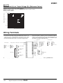
Wiring Terminals
• The voltage output (control output) is not electrically insulated from
the internal circuits. When using a grounding thermocouple, do not
connect the control output terminals to the ground. If the control
output terminals are connected to the ground, errors will occur in
the measured temperature values as a result of leakage current.
• Standard insulation is applied to the power supply I/O sections. If
reinforced insulation is required, connect the input and output terminals to a device without any exposed current-carrying parts or to
a device with standard insulation suitable for the maximum operating voltage of the power supply I/O section.
Event input
Contact inputs
Current output
4 DC to 20 mA
Voltage output
12 VDC
40 mA
Relay output Input power supply
Control output 1
Communications
Non-contact input
RS-232C
11 ←SD
RS-485
11 ←B (+)
12 ←RD
12 ←A (−)
13 ←SG
13 ←Do not use
Heater burnout
detection input
Alarm output
Alarm output
ALM2
Temperature
Controller
ALM3/Control
output 2
Analog input
ALM1/Heater
burnout
Note: Two input power supplies are available: 100 to 240 VAC or 24 VDC. Recommende power supply for 24VDC; eg. OMRON S8VS.
Digital Temperature Controllers
E5EN
I-33
Nomenclature
Operation
indicators
Temperature
unit
No.1 display
No.2 display
Operation
indicators
Mode key
Up key
Level key
Down key
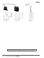
Dimensions
Note: All units are in millimeters unless otherwise indicated.
Panel Cutouts
Mounted Separately
11.5
48
Group Mounted
(48 × number of units -2.5) +1.0
0
84.5
78
PV
OUT1 OUT2 STOP CMW
120 min.
92.3
112
HB
96
ALM1 ALM2 ALM3
SV
E5EN
I-34
Digital Temperature Controllers E5EN
Group mounting does
not allow waterproofing.
• Recommended panel thickness is 1 to 8 mm.
• Group mounting is not possible in the vertical
direction. (Maintain the specified mounting
space between Controllers when they are
group mounted.)
• To mount the E5EN so that it is waterproof,
apply the waterproof packing to the E5EN.
• When two or more E5ENs are mounted, make
sure that the surrounding temperature does not
exceed the allowable operating temperature
specified in the specifications.
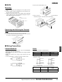
Current Transformer (Sold Separately)
Terminal Cover
E54-CT1
E53-COV11
E54-CT3
13
2.36 dia.
5.8 dia.
12 dia.
92.3
40 x 40
Two, M3 (depth: 4)
6.5
10.5
8
Temperature
Controller
Two, 3.5 dia.
6.5 dia.
Digital Temperature Controllers
E5EN
I-35
ALL DIMENSIONS SHOWN ARE IN MILLIMETERS.
To convert millimeters into inches, multiply by 0.03937. To convert grams into ounces, multiply by 0.03527.
I-36
Digital Temperature Controllers E5EN
Digital Temperature Controllers
E5AN
Compact and Intelligent Temperature
Controllers
• Depth of only 78 mm.
• Various temperature inputs: thermocouple, platinum resistance
thermometer, infrared temperature sensor, and analog inputs.
• Auto-tuning and self-tuning available. Auto-tuning is possible
even while self-tuning is being executed.
• Heating or heating/cooling control is available.
• Event input allows multiple SP selection and run/stop function.
• Water-resistant construction (NEMA4X: equivalent to IP66).
• Conforms to UL, CSA, and IEC safety standards as well as CE
marking.
96(W) x 96(H) x 78(D) mm
Model Number Structure
■ Model Number Legend
E5AN- @ @ @ M @ -500
1
2
3
4
5
4. Option Unit
M:
Option Unit can be mounted
5. Input type
TC: Thermocouple
P:
Platinum resistance thermometer
Temperature
Controller
1. Output type
R:
Relay
Q:
Voltage (for driving SSR)
C:
Current
2. Number of alarms
3:
Three alarms
3. Heater burnout alarm
Blank:Not available
H:
Available
Ordering Information
■ Standard Models
Size
1/4 DIN
96(W) x 96(H) x
78(D) mm
Power supply
voltage
100 to 240 VAC
No. of alarm
points
3
Control output
Relay
Voltage
(for driving SSR)
24 VAC/VDC
3
Heater burnout
alarm
Thermocouple model Platinum resistance
thermometer model
No
E5AN-R3MTC-500
E5AN-R3MP-500
Yes
E5AN-R3HMTC-500
E5AN-R3HMP-500
No
E5AN-Q3MTC-500
E5AN-Q3MP-500
Yes
E5AN-Q3HMTC-500
E5AN-Q3HMP-500
Current
No
E5AN-C3MTC-500
E5AN-C3MP-500
Relay
No
E5AN-R3MTC-500
E5AN-R3MP-500
Yes
E5AN-R3HMTC-500
E5AN-R3HMP-500
Voltage
(for driving SSR)
No
E5AN-Q3MTC-500
E5AN-Q3MP-500
Yes
E5AN-Q3HMTC-500
E5AN-Q3HMP-500
Current
No
E5AN-C3MTC-500
E5AN-C3MP-500
Note 1. A Current Transformer (CT) is not provided with the Unit. If using a heater burnout alarm, be sure to order one when ordering the E5AN.
2. When the heating and cooling function or the heater burnout alarm is used, one of the alarm outputs will be disabled for each function used.
Digital Temperature Controllers E5AN
I-37
3. Specify the power supply specifications when ordering.
■ Option Units
The E5AN provides communication or event input functionality when
mounted with one of the following Option Units.
Name
Communication Unit
Event Input Unit
Model
Function
E53-AK01
RS-232C communication
E53-AK03
RS-485 communication
E53-AKB
Event input
■ Current Transformer (Sold
Separately)
Model
E54-CT1
E54-CT3
Hole diameter
5.8 dia.
12.0 dia.
■ Terminal Cover
Model
E53-COV11
Note: The Terminal Cover comes with the E5AN and does not have
to be purchased separately.
Specifications
■ Ratings
Supply voltage
100 to 240 VAC, 50/60 Hz
Operating voltage range
85% to 110% of rated supply voltage
Power consumption
9 VA
Sensor input
Thermocouple:
Platinum resistance thermometer:
Infrared temperature sensor:
Voltage input:
Control output
24 VAC, 50/60 Hz/24 VDC
5 VA/4 W
K, J, T, E, L, U, N, R, S, B
Pt100, JPt100
10 to 70°C, 60 to 120°C, 115 to 165°C, 160 to 260°C
0 to 50 mV
Relay output
SPST-NO, 250 VAC, 5 A (resistive load), electrical life: 100,000 operations
Voltage output
12 VDC +15%/−20% (PNP), max. load current: 40 mA, with short-circuit protection circuit
Current output
4 to 20 mA DC, load: 600 Ω max., resolution: approx. 2,600
Alarm output
SPST-NO, 250 VAC, 3 A (resistive load), electrical life: 100,000 operations
Control method
2-PID or ON/OFF control
Setting method
Digital setting using front panel keys
Indication method
7-segment digital display and single-lighting indicator
Character height: PV: 15.0 mm; SV: 9.5 mm
Other functions
According to Controller model
Ambient temperature
−10 to 55°C (with no condensation or icing)
Ambient humidity
25% to 85%
Storage temperature
−25 to 65°C (with no condensation or icing)
I-38
Digital Temperature Controllers E5AN
■ Input Ranges
Platinum Resistance Thermometer Input/Thermocouple Input
Platinum resistance thermometer input
Input type
Platinum resistance thermometer
Temperature range
Name
1800
1700
1600
1500
1400
1300
1200
1100
1000
900
800
700
600
500
400
300
200
100
0
−100
−200
Set value
Pt100
JPt100
850
500.0
−200
−199.9
0
1
500.0
100.0
100.0
0.0
0.0
−199.9
2
3
4
Thermocouple input
Input type
K
Set value
J
T
E
L
U
N
R
S
1700
1700
B
K10 to
70°C
Analog input
K60 to K115 to K160 to
120°C 165°C 260°C
1800
1300
1300
850
0 to 50 mV
Usable in the
following
ranges by
scaling:
−1999 to 9999
or −199.9 to
999.9
850
600
Temperature
Controller
Temperature range
Name
1800
1700
1600
1500
1400
1300
1200
1100
1000
900
800
700
600
500
400
300
200
100
0
−100
−200
ES1A Infrared
Temperature Sensor
Thermocouple
500.0
400.0
400
400.0
400
400.0
260
120
165
0
0
0
0
12
13
14
15
70
100
−20.0
−20.0
0
−100
−200
0
1
2
3
−200
−199.9
4
17
−100
5
6
−200
−199.9
−200
7
18
8
0
0
9
10
11
16
Applicable standards by input type are as follows:
K, J, T, E, N, R, S, B: JIS C1602-1995
L: Fe-CuNi, DIN 43710-1985
U: Cu-CuNi, DIN 43710-1985
JPt100: JIS C1604-1989, JIS C1606-1989
Pt100: JIS C1604-1997, IEC751
Shaded ranges indicate default settings.
ES1A models with a temperature range of 160°C to 260°C have been discontinued.
Digital Temperature Controllers E5AN
I-39
■ Characteristics
Indication accuracy
Thermocouple:
(±0.5% of indicated value or ±1°C, whichever greater) ±1 digit max. (see note)
Platinum resistance thermometer:
(±0.5% of indicated value or ±1°C, whichever greater) ±1 digit max.
Analog input: ±0.5% FS±1 digit max.
CT input: ±5% FS±1 digit max.
Hysteresis
0.1 to 999.9 EU (in units of 0.1 EU)
Proportional band (P)
0.1 to 999.9 EU (in units of 0.1 EU)
Integral time (I)
0 to 3999 s (in units of 1 s)
Derivative time (D)
0 to 3999 s (in units of 1 s)
Control period
1 to 99 s (in units of 1 s)
Manual reset value
0.0% to 100.0% (in units of 0.1%)
Alarm setting range
−1999 to 9999 (decimal point position depends on input type)
Sampling period
500 ms
Insulation resistance
20 MΩ min. (at 500 VDC)
Dielectric strength
2000 VAC, 50 or 60 Hz for 1min (between different charging terminals)
Vibration resistance
10 to 55 Hz, 10 m/s2 for 2 hours each in X, Y and Z directions
Shock resistance
300 m/s2, 3 times each in 3 axes, 6 directions (relay: 100 m/s2)
Weight
Approx. 310 g
Degree of protection
Front panel: NEMA4X for indoor use (equivalent to IP66), rear case: IP20, terminals: IP00
Memory protection
EEPROM (non-volatile memory) (number of writes: 100,000)
EMC
Emission Enclosure:
Emission AC Mains:
Immunity ESD:
Approved standards
UL3121-1, CSA22.2 No. 142, E.B.1402C
Conforms to EN50081-2, EN50082-2, EN61010-1 (IEC61010-1)
Conforms to VDE0106/part 100 (Finger Protection), when the terminal cover is mounted.
Mounting bracket: Approx. 60 g
EN55011 Group 1 class A
EN55011 Group 1 class A
EN61000-4-2: 4 kV contact discharge (level 2)
8 kV air discharge (level 3)
Immunity RF-interference:
ENV50140:
10 V/m (amplitude modulated, 80 MHz to
1 GHz) (level 3)
10 V/m (pulse modulated, 900 MHz)
Immunity Conducted Disturbance: ENV50141:
10 V (0.15 to 80 MHz) (level 3)
Immunity Burst:
EN61000-4-4: 2 kV power-line (level 3)
2 kV I/O signal-line (level 4)
Note: The indication of K thermocouples in the −200 to 1300°C range, and T and N thermocouples at a temperature of −100°C or less, and U and
L thermocouples at any temperature is ±2°C±1 digit maximum. The indication of B thermocouples at a temperature of 400°C or less is unrestricted.
The indication of R and S thermocouples at a temperature of 200°C or less is ±3°C±1 digit maximum.
■ Communications Specifications
Transmission path connection
RS-485:
Multiple points
RS-232C: Point-to-point
Communications method (see note 1)
RS-485 (two-wire, half duplex)/RS-232C
Synchronization method
Start-stop synchronization
Baud rate
1,200/2,400/4,800/9,600/19,200 bps
Transmission code
ASCII
Data bit length (see note 2)
7 or 8 bits
Stop bit length (see note 2)
1 or 2 bits
Error detection
Vertical parity (none, even, odd)
Frame check sequence (FCS): with SYSWAY
Block check character (BCC): with CompoWay/F
Flow control
Not available
Interface (see note 1)
RS-485/RS-232C
Retry function
Not available
Communications buffer
40 bytes
Note 1. RS-232C communications are only supported for the E5AN and E5EN models.
2. The baud rate, data bit length, stop bit length, or vertical parity can be individually set using the communications setting level.
I-40
Digital Temperature Controllers E5AN
■ Current Transformer (Sold Separately) Ratings
Dielectric strength
1,000 VAC (1 min)
Vibration resistance
50 Hz 98 m/s2
Weight
E54-CT1: Approx. 11.5 g
E54-CT3: Approx. 50 g
Accessories (E54-CT3 only)
Armature (2)
Plug (2)
■ Heater Burnout Alarm Specifications
Max. heater current
Single-phase AC: 50 A (see note 1)
Input current readout accuracy
±5%FS±1 digit max.
Heater burnout alarm setting range
0.0 to 50.0 A (0.1 A units) (see note 2)
Min. detection ON time
190 ms (see note 3)
Note 1. When heater burnout is detected on a 3-phase heater, use the K2CU-F@@A-@GS (with gate input terminal).
2. When the set value is “00 A,” the heater burnout alarm will always be OFF. When the set value is “50.0 A,” the heater burnout alarm will
always be ON.
3. When the control output ON time is less than 190 ms, heater burnout detection and heater current measurement will not be carried out.
■ Engineering Data
Electrical Life Expectancy Curve for Relays (Reference Values)
Life expectancy (×104 operations)
500
300
E5AN, E5EN
250 VAC, 30 VDC
(resistive load)
cosφ = 1
100
50
30
10
5
E5CN
250 VAC, 30 VDC
(resistive load)
cosφ = 1
3
1
0
1
2
3
4
5
6
Temperature
Controller
Switching current (A)
E54-CT1
Thru-current (Io) vs. Output Voltage (Eo) (Reference Values)
Output voltage (Eo) V (r.m.s.)
Maximum continuous heater current: 50 A (50/60 Hz)
Number of windings: 400±2
Winding resistance: 18±2 Ω
100 V 50 Hz
∞
1 kΩ
10
Distortion
factor 10%
1
3%
1%
100 mV
100 Ω
10
RL = 10 Ω
1
100 µV
10
1
10
100 mA
1
10
100 1,000 A
Thru-current (Io) A (r.m.s.)
Digital Temperature Controllers E5AN
I-41
E54-CT3
Thru-current (Io) vs. Output Voltage (Eo) (Reference Values)
Output voltage (Eo) V (r.m.s.)
Maximum continuous heater current: 120 A (50/60 Hz)
(Maximum continuous heater current for an OMRON Temperature Controller is 50 A.)
Number of windings: 400±2
Winding resistance: 8±0.8 Ω
100 V 50 Hz
∞
1 kΩ
500 Ω
10
Distortion
factor 10%
3%
1%
1
100 mV
100 Ω
50 Ω
10
RL = 10 Ω
1
100 µV
10
1
10
100 mA
1
10
100 1,000 A
Thru-current (Io) A (r.m.s.)
Wiring Terminals
• The voltage output (control output) is not electrically insulated from
the internal circuits. When using a grounding thermocouple, do not
connect the control output terminals to the ground. If the control
output terminals are connected to the ground, errors will occur in
the measured temperature values as a result of leakage current.
• Standard insulation is applied to the power supply I/O sections. If
reinforced insulation is required, connect the input and output terminals to a device without any exposed current-carrying parts or to
a device with standard insulation suitable for the maximum operating voltage of the power supply I/O section.
Event input
Contact inputs
Current output
Voltage output
4 DC to 20 mA
12 VDC
40 mA
Relay output
Communications
Non-contact input
Input power supply
Control output 1
RS-232C
RS-485
11 ←SD
11 ←B (+)
12 ←RD
12 ←A (−)
13 ←SG
13 ←Do not use
Heater burnout
detection input
ALM3/Control
output 2
Alarm output
ALM2
Analog input
ALM1/Heater
burnout
Note: Two input power supplies are available: 100 to 240 VAC or 24 VDC. Recommende power supply for 24VDC; eg. OMRON S8VS.
I-42
Digital Temperature Controllers E5AN
Nomenclature
Temperature
unit
Operation
indicators
No.1 display
No.2 display
Up key
Level key
Down key
Mode key
Dimensions
Note: All units are in millimeters unless otherwise indicated.
Panel Cutouts
Group Mounted
(96 × number of units -3.5) +1.0
0
Temperature
Controller
120 min.
Mounted Separately
Group mounting does
not allow waterproofing.
• Recommended panel thickness is 1 to 8 mm.
• Group mounting is not possible in the vertical
direction. (Maintain the specified mounting
space between Controllers when they are
group mounted.)
• To mount the E5AN so that it is waterproof,
apply the waterproof packing to the E5AN.
• When two or more E5ANs are mounted, make
sure that the surrounding temperature does
not exceed the allowable operating
temperature specified in the specifications.
Digital Temperature Controllers E5AN
I-43
Current Transformer (Sold Separately)
Terminal Cover
E54-CT1
E53-COV11
E54-CT3
2.36 dia.
5.8 dia.
6.5 dia.
92.3
40 x 40
Two, 3.5 dia.
13
12 dia.
Two, M3 (depth: 4)
6.5
10.5
8
ALL DIMENSIONS SHOWN ARE IN MILLIMETERS.
To convert millimeters into inches, multiply by 0.03937. To convert grams into ounces, multiply by 0.03527.
I-44
Digital Temperature Controllers E5AN
Nomenclature
E5AN
Operation Indicators
1. ALM1 (alarm 1)
Lights when alarm 1 output is ON.
ALM2 (alarm 2)
Lights when alarm 2 output is ON.
ALM3 (alarm 3)
Lights when alarm 3 output is ON.
Temperature Unit
The temperature unit is displayed when the display unit parameter is set to a temperature. Indication is determined by the currently selected
"temperature unit" parameter set value. When
this parameter is set to "°C," "c" is displayed,
and when set to "°F," "f" is displayed.
No. 1 Display
Displays the process value or parameter type.
No. 2 Display
Displays the set point, manipulated
variable, or set value (setup) of the
parameter.
2. HB (heater burnout alarm display)
Lights when a heater burnout is detected.
The heater burnout alarm remains ON by setting the
heater burnout latch. To reset, turn the power supply
OFF and then ON or set the heater burnout alarm value
to "0.0A."
Up Key
Each press of this key increases values displayed on the No.2 display.
Holding down this key continuously
increases values.
3. OUT1, OUT2 (control output 1, control output 2)
Lights when control output 1 and/or control output 2
(cool) are ON.
However, if control output 1 is current output, OUT1 will
always be unlit.
4. STOP (stop)
Lights when control of the E5AN has been stopped.
During control, this indicator lights when an event or the
run/stop function has become stopped. Otherwise, this
indicator is out.
Down Key
Each press of this key decreases values displayed on the No.2 display.
Holding down this key continuously decreases values.
5. CMW (communications writing control)
Lights when communications writing is enabled and is
out when it is disabled.
Mode Key
Level Key
Press this key to select the setup level. The setup level is
selected in order "operation level" ←→ "adjustment level,"
"initial setting level" ←→ "communications setting level."
Press this key to select parameters
within each level.
Level + Mode Keys
This key combination sets the E5AN
to the "protect level."
E5EN
Temperature Unit
No. 1 Display
The temperature unit is displayed when the display unit parameter is set to a temperature. Indication is determined by the currently selected
"temperature unit" parameter set value. When
this parameter is set to "°C," "c" is displayed,
and when set to "°F," "f" is displayed.
Displays the process value or parameter type.
3.
No. 2 Display
Displays the set point, manipulated
variable, or set value (setup) of the parameter.
2. HB (heater burnout alarm display)
Lights when a heater burnout is detected.
The heater burnout alarm remains ON by setting the
heater burnout latch. To reset, turn the power supply
OFF and then ON or set the heater burnout alarm
value to "0.0A."
Up Key
OUT1, OUT2 (control output 1, control output 2)
Lights when control output 1 and/or control output 2
(cool) are ON.
However, if control output 1 is current output, OUT1
will always be unlit.
Each press of this key increases values displayed on the No.2 display.
Holding down this key continuously
increases values.
4. STOP (stop)
Lights when control of the E5EN has been
stopped.During control, this indicator lights when an
event or the run/stop function has become stopped.
Otherwise, this indicator is out.
Down Key
Each press of this key decreases values displayed on the No.2 display.
Holding down this key continuously
decreases values.
5. CMW (communications writing control)
Lights when communications writing is enabled and
is out when it is disabled.
Level Key
Press this key to select the setup level. The setup level is selected in order
"operation level" ←→ "adjustment
level," "initial setting level" ←→
"communications setting level."
Mode Key
Press this key to select parameters within
each level.
Digital Temperature Controllers
Level + Mode Keys
This key combination sets the E5EN
to the "protect level."
E5GN/E5CN/E5EN/E5AN
I-45
Temperature
Controller
Operation Indicators
1. ALM1 (alarm 1)
Lights when alarm 1 output is ON.
ALM2 (alarm 2)
Lights when alarm 2 output is ON.
ALM3 (alarm 3)
Lights when alarm 3 output is ON.
E5CN
Operation Indicators
Temperature Unit
No. 1 Display
1. AL1 (alarm 1)
Lights when alarm 1 output is ON.
AL2 (alarm 2)
Lights when alarm 2 output is ON.
The temperature unit is displayed when the display unit parameter is set to a temperature. Indication is determined by the currently selected
"temperature unit" parameter set value. When
this parameter is set to "°C," "c" is displayed, and
when set to "°F," "f" is displayed.
Displays the process value or parameter type.
2. HB (heater burnout alarm display)
Lights when a heater burnout is detected.
The heater burnout alarm remains
ON by setting the heater burnout
latch. To reset, turn the power supply
OFF and then ON or set the heater
burnout alarm value to "0.0A."
No. 2 Display
Displays the set point, manipulated variable,
or set value (setup) of the parameter.
3. OT1, OT2 (control output 1, control
output 2)
Lights when control output 1 and/or
control output 2 (cool) are ON.
However, if control output 1 is current
output, OT1 will always be unlit.
Up Key
Each press of this key increases values
displayed on the No.2 display. Holding
down this key continuously increases
values.
4. STP (stop)
Lights when control of the E5CN has
been stopped.
During control, this indicator lights
when an event or the run/stop function has become stopped. Otherwise,
this indicator is out.
Down Key
Each press of this key decreases values
displayed on the No.2 display. Holding
down this key continuously decreases
values.
5. CMW (communications writing control)
Lights when communications writing
is enabled and is out when it is disabled.
Mode Key
Press this key to select parameters within
each level.
Level Key
Press this key to select the setup level. The setup level is
selected in order "operation level" ←→ "adjustment level,"
"initial setting level" ←→ "communications setting level."
Level + Mode Keys
This key combination sets the E5CN to the
"protect level."
E5GN
Operation Indicators
Temperature Unit
1. AL (alarm)
Lights when alarm output is ON.
The temperature unit is displayed when the display unit parameter is set to a temperature. Indication is determined by the currently selected
"temperature unit" parameter set value. When
this parameter is set to "°C," "c" is displayed,
and when set to "°F," "f" is displayed.
2. CMW (communications writing control)
Lights when communications writing is
enabled and is out when it is disabled.
3. STP (stop)
Lights when control of the E5GN has
been stopped.
During control, this indicator lights when
an event or the run/stop function has been
stopped. Otherwise, this indicator is out.
No. 1 Display
Displays the process value or parameter type.
4. OUT (control output)
Lights when control output is ON.
No. 2 Display
Displays the set point, manipulated variable or
set value (setup) of the parameter.
Up Key
Level Key
Press this key to select the setup level. The
setup level is selected in order "operation level"
←→ "adjustment level," "initial setting level"
←→ "communications setting level."
Mode Key
Press this key to select parameters
within each level.
I-46
Each press of this key increases values displayed on
the No.2 display. Holding down this key continuously
increases values.
Down Key
Each press of this key decreases values displayed on
the No.2 display. Holding down this key continuously
decreases values.
Level + Mode Key
This key combination sets the E5GN to the
"protect level."
Digital Temperature Controllers E5GN/E5CN/E5EN/E5AN
Installation
■ E5AN/E5EN
Drawing Out
Mounting
For drawing out the Unit, use a suitable Phillips screwdriver for the
screw located at the bottom on the front panel.
1. Insert the E5AN/E5EN into the mounting hole in the panel from
the front.
2. Push the mounting bracket along the E5AN/E5EN body from the
terminals up to the panel, and secure it temporarily.
3. Tighten the fixing screw on each mounting bracket alternately
until the ratchet stops tightening.
E5AN
Panel
1. While pressing down on the hook located at the top of the front
panel, turn the screw (located at the bottom on the front panel)
counterclockwise using a Phillips screwdriver.
2. Hold both sides of the front panel and draw out the Unit towards
you.
3. When inserting the Unit, confirm that the waterproof packing is in
place. While pressing down on the hook located at the top of the
front panel, turn the screw (located at the bottom on the front
panel) clockwise using a Phillips screwdriver and tighten to a
torque of 0.3 to 0.5 N·m. Make sure that electronic parts do not
come in contact with the case.
Mounting bracket
(1)
(1)
(2)
(2)
(3)
(3)
(1)
(3)
Waterproof
packing
E5EN
Mounting bracket
Temperature
Controller
Panel
Waterproof
packing
Digital Temperature Controllers
E5GN/E5CN/E5EN/E5AN
I-47
■ E5CN
Mounting
Adapter
Setting Up Option Units
Panel
If communications, event input, or heater burnout functions are
required, mount the E53-CNH03/E53-CN03 Communications Unit or
the E53-CNHB/E53-CNB Event Input Unit. The heater burnout function is supported on either of these two Option Units.
Option Units
Name
Model
Function
Communications Unit E53-CNH03
E53-CN03
RS-485 communications
Event Input Unit
Event inputs
E53-CNHB
E53-CNB
1. Insert the E5CN into the mounting hole in the panel.
2. Push the adapter along the E5CN body from the terminals up to
the panel, and secure it temporarily.
3. Tighten the two fixing screws on the adapter. When tightening
screws, tighten the two screws alternately keeping the torque to
between 0.29 and 0.39 N·m (2.9 kgf·cm to 3.9 kgf·cm).
Note: Terminal label: x1
Assembling a Unit
(1)
Flat-blade screwdriver
(unit: mm)
20 min.
(4)
Attaching the Terminal Cover
Make sure that the “UP” mark is facing up, and then fit the Terminal
Cover (E53-COV10) into the holes on the top and bottom. A E5CN@-500 Controller is provided with a Terminal Cover.
2.0
0.4
(2)
(1)
Attaching the E5CN to a Panel
(3)
1. Insert the tools (see drawing above) into the slots (one on the top
and one on the bottom) and release the hooks.
2. Insert the tool in the space between the front and rear panels and
slightly pull out the front panel. Hold the top and bottom of the
front panel and pull toward yourself to remove it.
3. Match up the upper and lower claws with the connection points
and insert the Option Unit. Mount the Option Unit in the center.
4. Before inserting the Unit, confirm that the waterproof packing is in
place. Insert the Unit into the rear case until you hear a click.
When inserting the Unit, press down the hooks on the top and
bottom of the rear case so that they firmly hook on the inserted
Unit. Make sure that electronic parts do not come in contact with
the case.
I-48
Digital Temperature Controllers E5GN/E5CN/E5EN/E5AN
■ E5GN
2. Draw out the terminal plate as it is.
Mounting
1. Insert the E5GN into the mounting hole in the panel from the
front.
2. Push the adapter along the E5GN body from the terminals up to
the panel, and secure it temporarily.
3. Tighten the two fixing screws on the adapter. When tightening
screws, tighten the two screws alternately keeping the torque to
within approximately 0.29 to 0.39 N·m.
3. Before you insert the terminal plate again, make sure that the pins
match the positions of the holes in the terminal plate.
Adapter
Waterproof packing
Panel
Removing and Attaching the Terminal
Plate
The E5GN can be replaced by removing the terminal plate.
1. Press down hard on the fasteners on both sides of the terminals
to unlock the terminal plate and pull upwards.
E5AN/E5EN/E5CN
E5GN
• Separate input leads and power lines to protect the E5AN/E5EN/
E5CN and its lines from external noise.
• We recommend using solderless terminals when wiring the E5AN/
E5EN/E5CN.
• Tighten the terminal screws using a torque between 0.74 and
0.90 N·m.
• Use the following type of solderless terminals for M3.5 screws.
• Connect the terminals as specified below.
Terminal No.
Cables
Temperature
Controller
■ Wiring Precautions
Pin terminals
1 to 6
AWG24 to AWG14
2.1 dia. max.
7 to 9
AWG28 to AWG22
1.3 dia. max.
• The exposed current-carrying part to be inserted into terminals
must be 5 to 6 mm.
7.2 mm max.
5 to 6 mm
5 to 6 mm
7.2 mm max.
Pin terminal
Electrical wire
• Tighten the terminal screws to the torque specified below.
Terminal No.
Screw
Maximum tightening
torque
1 to 6
M2.6
0.23 to 0.25 N·m
7 to 9
M2
0.12 to 0.14 N·m
Digital Temperature Controllers
E5GN/E5CN/E5EN/E5AN
I-49
Operation
■ Initial Setup
On previous Controllers, sensor input type, alarm type and control
period were set on DIP switches. These hardware settings are now
set in parameters in setup menus. The
and
keys are used to
switch between setup menus, and the amount of time that you hold
the keys down for determines which setup menu you move to. This
section describes two typical examples.
Note: On the E5EN/E5GN, the
Key is the
Key.
1. ON/OFF Control
Typical Application Examples
Typical Example
0 K thermocouple −200 to 1300˚C
Input type:
Control method: ON/OFF control
Alarm type:
2 upper limit
Alarm value 1:
20˚C (For setting deviation)
Set point:
100˚C
Change only the alarm value 1 and set point.
The rest must be left as default settings.
Setup procedure
Changing Parameters
Power ON
Power ON
Operation level
Process value/
set point
Press key for at least
three seconds.
Control stops.
Initial setting level
indicates that there is a parameter. Keep
on pressing the mode key until the desired
parameter is selected.
Changing Set Values
Set input
specifications
Check input
type.
Input type0
Set control
specifications
Check that control is ON/OFF
control.
In ON/OFF
control onof
Set alarm type
Check alarm
type.
Alarm 1
type 2
Use the
or
keys to
change the set value displayed
in the setup menu.
Display
E5AN
Press key for at
least one second.
Control starts.
No. 1 display
Operation level
No. 2 display
Set the set point
E5EN
No. 1 display
Check operation
state
Press
keys
to set set point to
"100°C."
Make sure that
control is running.
No. 2 display
Set alarm values
Press
keys
to set alarm value
to "20°C."
E5CN
No. 1 display
No. 2 display
Start operation
E5GN
No. 1 display
No. 2 display
I-50
Digital Temperature Controllers E5GN/E5CN/E5EN/E5AN
Start operation
PV/
SP 100
During run
run
During stop
Alarm value
1
2. PID Control Using Autotuning
Typical Example
Changing Parameters
4 T thermocouple −200 to 400°C
Input type:
Control method: PID control
ST (self-tuning): OFF
Calculate PID constants by AT (auto-tuning).
Alarm type:
indicates that there is a parameter. Keep on pressing
the mode key until the desired parameter is selected.
2 upper limit
Alarm value 1:
30°C (For setting deviation)
Set point:
150°C
Setup procedure
Power ON
Power ON
Operation level
Process value/
set point
Changing Set Values
Use the
or
keys
to change the set value
displayed in the setup
menu.
Press key for at least three
seconds.
Control stops.
Display
Set input
specifications
E5AN
No. 1 display
No. 2 display
E5EN
In PID control
Press
keys to select
PID control.
Self-tuning
Press
keys to set
ST to OFF.
To cancel ST
Check the
control period.
Control period
(heat) (unit:
seconds)
Check alarm type
Check alarm
type.
Alarm 1 type 2
(upper-limit
alarm)
Set the set point
Operation level
Press
keys
to set set point to
"150°C."
Check control
period
E5CN
No. 1 display
PV/SP
Press
After AT execution.
When set to ON,
self-tuning operates.
Recommended settings: 20 seconds for
the relay output and
2 seconds for the
SSR output.
key for at least one second.
PV/
SP 150
During AT execution.
Temperature
Controller
No. 2 display
Input type 4
Set control
specifications
No. 1 display
No. 2 display
Initial setting level
Press
keys to select
input type.
Press key for less than one second.
E5GN
No. 1 display
Adjustment level
While AT is being
executed, SP will flash.
AT execution
Execute AT
(auto-tuning).
To execute AT
After AT execution.
Set to on for executing AT and to off
for stopping AT.
Press key for less than one second.
No. 2 display
Operation level
During AT execution.
Make sure
that set point
is "150°C."
Set operation status
Set alarm values
PV/
SP150
Make sure that
control is running.
During run
Press
keys to set
alarm value to
"30°C."
Alarm
value 1
30
Start operation
Digital Temperature Controllers
Start operation
E5GN/E5CN/E5EN/E5AN
I-51
■ Specification Setting after Turning ON Power
Outline of Operation Procedures
Key Operation
In the following descriptions, all the parameters are introduced in the display sequence. Some parameters may not be displayed depending on the
protect settings and operation conditions.
Power ON
Operation level
Adjustment level
key
Less than
1 second
key
1 second
min.
key
3 seconds
min.
+
key
Display flashes when key pressed.
+
key
1 second min.
key
Display flashes when key held
down for more than 1 second.
Control stops.
Initial setting level
key
Less than
1 second
Communications setting
level
+
key
3 seconds min.
Protect level
Note: 1. Of these levels, the initial setting level, communications
setting level, advanced function setting level and calibration level can be used only when control has stopped. Note that control is stopped when these four levels
are selected. When switched back to the operation level
from one of these levels, control will start.
2. For the calibration mode, refer to the relevant User's
Manual.
3. On the E5EN/E5GN, the
Key is the
Key.
Password input
set value "−169"
key
1 second min.
The time taken to move to the protect level
can be adjusted by changing the "Move to
protect level time" setting.
Advanced function
setting level
Password input
set value "1201"
Control in progress
Calibration level
Control stopped
Level change
Description of Each Level
Protect Level
Operation Level
To select this level, simultaneously press the
and
keys for at
least 3 seconds. This level is to prevent unwanted or accidental modification of parameters. Protected levels will not be displayed, and so
the parameters in that level cannot be modified.
This level is displayed when you turn the power ON. You can move to
the protect level, initial setting level and adjustment level from this
level.
Normally, select this level during operation. During operation, the
process value, set point and manipulated variable can be monitored,
and the alarm value and upper- and lower-limit alarms can be monitored and modified.
Adjustment Level
To select this level, press the
key once for less than one second.
This level is for entering set values and offset values for control. This
level contains parameters for setting the set values, AT (auto-tuning),
communications writing enable/disable, hysteresis, multi-SP, input
shift values, heater burnout alarm (HBA) and PID constants. You can
move to the top parameter of the operation level or initial setting level
from here.
Initial Setting Level
Communications Setting Level
To select this level, press the
key once for less than one second in
the initial setting level. When the communications function is used,
set the communications conditions in this level. Communicating with
a personal computer (host computer) allows set points to be read
and written, and manipulated variables to be monitored.
Advanced Function Setting Level
To select this level, you must enter the password (“-169”) in the initial
setting level.
You can move only to the calibration level from this level.
This level is for setting the automatic return of display mode, MV limiter, event input assignment, standby sequence, alarm hysteresis, ST
(self-tune) and to move to the user calibration level.
To select this level, press the
key for at least three seconds in the
operation level. This level is for specifying the input type, selecting
the control method, control period, setting direct/reverse action and
alarm type. You can move to the advanced function setting level or
communications setting level from this initial setting level. To return to
Calibration Level
the operation level, press the
key for at least one second. To
move to the communications setting level, press the
key once for
less than one second.
You cannot move to other levels by operating the keys on the front
panel from the calibration level. To cancel this level, turn the power
OFF then back ON again.
I-52
To select this level, you must enter the password (“1201”) in the
advanced function setting level. This level is for offsetting deviation in
the input circuit.
Digital Temperature Controllers E5GN/E5CN/E5EN/E5AN
Specification Setting after Turning ON Power
Initial Setting Level
Initial setting level
This level is used for setting basic specifications of the Temperature
Controller. Using this level, set the input type for selecting the input to
be connected such as the thermocouple or platinum resistance thermometer and set the range of set point and the alarm mode.
Input type
Scaling upper limit
key
+
Display flashes
when key pressed.
Power ON
Operation level
Adjustment level
key
Less than 1 second
key
1 second min.
key
3 seconds
min.
Initial setting
level
key
1 second min.
Scaling lower limit
key
+
1 second min.
Decimal point
key
+
3 seconds
min.
Control stops.
Temperature
unit
Communications setting
key level
Less than 1 second
Password input
set value "−169"
Advanced function
setting level
For analog input
(Input type: 16)
0- to 50-mV setting
Protect level
SP upper limit
The time taken to move
to the protect level can
be adjusted by changing
the "Move to protect level time" setting.
SP lower limit
Password input
set value "1201"
Control in progress
PID ON/OFF
onof: ON/OFF control
pid: PID control
Standard or heating/
cooling
Alarm output type
stnd: Standard
h-c: Heating/cooling
Control stopped
Level change
The move from the operation level to the initial setting level, press
key for three seconds or more.
The initial setting level is not displayed when “initial/communications
protection” is set to “2.” This initial setting level can be used when
“initial setting/communications protection” is set to “0” or “1.”
ST
(PID control)
on: Enabled
off: Disabled
Control period (heat)
The “scaling upper limit,” “scaling lower limit,” and “decimal point”
parameters are displayed when an analog voltage input is selected
as the input type.
Control period (cool)
(PID control)
(Heating/cooling setting)
Direct/reverse operation
Set the pulse output
cycle.
or-r: Reverse
operation
or-d: Direct
operation
Alarm 1 type
Alarm 2 type
Temperature
Controller
Calibration level
Select the alarm mode.
(Models with alarm
function)
Alarm 3 type
(E5AN/E5EN)
Move to advanced
function setting level
(When initial/communications protect is set to "0".)
To return to the operation level, press the
second.
*
key for longer than one
Not displayed as default setting.
Digital Temperature Controllers
E5GN/E5CN/E5EN/E5AN
I-53
Input Type
When using a thermocouple input type, follow the specifications listed in the following table.
Input Type
Thermocouple input type
Specifications
Thermocouple
Analog input
Input Temperature Range
−200 to 1300 (°C)
/−300 to 2300 (°F)
1
−20.0 to 500.0 (°C)
/0.0 to 900.0 (°F)
2
−100 to 850 (°C)
/−100 to 1500 (°F)
3
−20.0 to 400.0 (°C)
/0.0 to 750.0 (°F)
T
4
−200 to 400 (°C)
/−300 to 700 (°F)
E
5
0 to 600 (°C)
/0 to 1100 (°F)
U
17
−199.9 to 400.0 (°C) /−199.9 to 700 (°F)
L
6
−100 to 850 (°C)
/−100 to 1500 (°F)
U
7
−200 to 400 (°C)
/−300 to 700 (°F)
U
18
−199.9 to 400.0 (°C) /−199.9 to 700 (°F)
N
8
−200 to 1300 (°C)
/−300 to 2300 (°F)
R
9
0 to 1700 (°C)
/0 to 3000 (°F)
S
10
0 to 1700 (°C)
/0 to 3000 (°F)
B
11
100 to 1800 (°C)
/300 to 3200 (°F)
J
Infrared temperature sensor
ES1A
Set Value
0
K
K10 to 70°C
12
0 to 90 (°C)
/0 to 190 (°F)
K60 to 120°C
13
0 to 120 (°C)
/0 to 240 (°F)
K115 to 165°C
14
0 to 165 (°C)
/0 to 320 (°F)
K160 to 260°C
15
0 to 260 (°C)
/0 to 500 (°F)
0 to 50mV
16
One of following ranges depending on the
results of scaling: 1999 to 9999, 199.9 to
999.9
Note: The initial settings are: 0: -200 to 1300°C/-300 to 2300°F.
When using the platinum resistance thermometer input type, follow the specifications listed in the following table.
Input Type
Platinum resistance thermometer input type
Platinum resistance thermometer
Specifications
Pt100
JPt100
Set Value
Input Temperature Range
0
−200 to 850 (°C)
1
−199.9 to 500.0 (°C) /−199.9 to 900.0 (°F)
2
0.0 to 100.0 (°C)
3
−199.9 to 500.0 (°C) /−199.9 to 900.0 (°F)
4
0.0 to 100.0 (°C)
Note: The initial settings are: 0: Pt100 -200 to 850°C/-300 to 1500°F.
I-54
Digital Temperature Controllers E5GN/E5CN/E5EN/E5AN
/−300 to 1500 (°F)
/0.0 to 210.0 (°F)
/0.0 to 210.0 (°F)
Alarm 1 and Alarm 2
For the alarm 1 and alarm 2, select alarm types out of the 12 alarm types listed in the following table. (The alarm 3 for E5AN/E5EN, which has
three alarms, can also be selected from this table.)
Set Value
Alarm Type
Alarm Output Operation
When X is positive
When X is negative
0
Alarm function OFF
Output OFF
1*1
Upper- and lower-limit (deviation)
2
Upper-limit (deviation)
3
Lower-limit (deviation)
4*1
Upper- and lower-limit range (deviation)
*3
5*1
Upper- and lower-limit with standby sequence (deviation)
*4
6
Upper-limit with standby sequence (deviation)
7
Lower-limit with standby sequence (deviation)
8
Absolute-value upper-limit
9
Absolute-value lower-limit
10
Absolute-value upper-limit with standby
sequence
11
Absolute-value lower-limit with standby
sequence
*2
*5
*2: Set value: 1, Upper- and lower-limit alarm
Case 1
Case 2
Case 3 (Always ON)
=
*3: Set value: 4, Upper- and lower-limit range
Case 2
Case 1
Case 2
Example
Same as for the upper- and lower-limit
alarm. However, when the upper-limit
and lower-limit hysteresis overlaps:
Always OFF
*5: Set value: 5, Upper- and lower-limit with standby sequence alarm.
Always OFF when the upper-limit and lower-limit hysteresis overlaps.
=
Case 1
*4: Set value: 5, Upper- and lower-limit with standby sequence
Case 3 (Always OFF)
L H
=
Set the alarm types for alarm 1 and alarm 2 independently in the initial setting level. The default setting is 2 (upper limit). With the E5AN/
E5EN, perform settings similarly for alarm 3.
Example: When the alarm is set ON at 110°C/°F or higher.
When an alarm type other
When the absolute-value
than the absolute-value
alarm is selected
alarm is selected
(For alarm types 8 to 11)
(For alarm types 1 to 7)
The alarm value is set as
The alarm value is set as a
an absolute value from the
deviation from the set point.
alarm value of 0°C/F.
Alarm value
Alarm value
=
Set point
100°C/°F
Digital Temperature Controllers
0°C/°F
E5GN/E5CN/E5EN/E5AN
I-55
Temperature
Controller
*1: With set values 1, 4 and 5, the upper and lower limit values can
be set independently for each alarm type, and are expressed as “L”
and “H.”
Following operations are for cases when an alarm set point is “X” or
negative.
Parameters
key 1 second min.
Parameters related to setting items for each level are marked in
boxes in the flowcharts and brief descriptions are given as required.
At the end of each setting item, press the mode key to return to the
beginning of each level.
Power ON
Advanced Function Setting Level
Number of multi-SP used
Select 2 or 4.
+ key
Display flashes
when key pressed.
Operation level
Event input assignment 1
Adjustment level
+
key
1 second
min.
+
key
Display flashes when key held
down for more than 1 second.
key
3 seconds
min.
Control stops.
Multi-SP uses
+
key
3 seconds
min.
SP ramp set value
Rate of change during ramp
Standby sequence reset
Restarting condition
after clearing standby
Communications setting
key level
Initial setting level
Protect level
Alarm 1 open in alarm
Less than 1 second
key
1 second
min.
Input setting:
Multiple
SP/RUN/STOP
Event input assignment 2
key
Less than 1 second
key
1 second
min.
Resets to the default value.
Parameter initialize
The time taken to
move to the protect
level can be adjusted
by changing the "Move
to protect level time"
setting.
Password input
set value "−169"
Advanced function
setting level
Alarm 1 hysteresis
ON/OFF setting of
alarm output 1
Alarm 2 open in alarm
ON/OFF setting of
alarm output 2
Password input
set value "1201"
Alarm 2 hysteresis
Control in progress
Calibration level
Alarm 3 open in alarm
ON/OFF setting of
alarm output 3
Control stopped
Level change
Alarm 3 hysteresis
Display
HBA ON/OFF
E5AN
Heater burnout latch
Latch after heater
burnout detection
No. 1 display
Heater burnout hysteresis
No. 2 display
ST stable range
For setting deviation.
Note: To select advanced
function setting
level, you must
enter the password
("−169") in the initial
setting level.
α
2-PID parameter
E5EN
MV upper limit
Limitations to MV
No. 1 display
MV lower limit
No. 2 display
E5CN
No. 1 display
E5GN
No. 1 display
Input digital filter
For setting time constant in seconds.
Additional PV display
Displayed first in the operation level
MV display
Automatic return of display mode
Input error output
Automatically reset to the operation level
when no key operation are performed.
No. 2 display
No. 2 display
Move to protect level time
Cold junction
compensating method
Alarm 1 latch
Alarm 2 latch
Alarm-ON
latches
MB command logic
switching
Alarm 3 latch
PV display color change
PV stable band
I-56
Digital Temperature Controllers E5GN/E5CN/E5EN/E5AN
Move to calibration level
Power ON
key 1 second min.
key Less than 1 second
Operation Level
Initial Setting Level
Adjustment Level
key Less than 1 second
key 3 seconds min.
PV
Input type
Scaling upper limit
Decimal point
Number of displayed digits
Temperature unit
c: °C
f: °F
Multi-SP Select SP.
Heater
current value
SP ramp monitor
Heater burnout
detection
Run/stop
SP lower limit
Upper-limit
alarm value
onof: ON/OFF control
pid: PID control
Standard or heating/cooling
Control period (heat)
OUT1
Upper-limit
alarm value
Set the pulse
output cycle.
SP 3
Set either of
these
parameters.
Alarm 1 type
Upper-limit
temperature input
2-point shift (see note)
Integral time
I
Derivative time
D
PID settings
Set either of
these
parameters.
Cooling coefficient
Lower-limit
alarm value
Select the alarm
mode.
1-point shift
Proportional band P
Alarm value 3
Upper-limit
alarm value 3
Temperature input shift
Lower-limit
temperature input
Lower-limit
alarm value
Direct/reverse operation
or-r: Reverse
Controls the MV in response
increases or decreases in the PV. or-d: Direct
Alarm 2 type
Set either of
these
parameters.
Alarm value 2
on: Enabled
off: Disabled
Control period (cool)
OUT2
SP used by multi-SP
SP 2
Lower-limit
alarm value
stnd: Standard
h-c: Heating/cooling
Self-tuning
SP 1
run: RUN
stop: STOP
Alarm value 1
PID ON/OFF
Select the control system.
HBA function
Current value
monitor of HBA
Limit the set point.
on: Enabled
off: Disabled
SP 0
Heater current value monitor
SP upper limit
Auto-tuning
Communications writing
PV/SP
For analog input
(Input type: 16)
0- to 50-mV setting
Scaling lower limit
AT execute/cancel
Add in the "additional
PV display" parameter.
Dead band
Used in heating and
cooling control
MV monitor (OUT 1)
Alarm 3 type
Manual reset value
Move to advanced function
setting level
Note: This parameter is not displayed as a default setting. To move to the advanced function setting
level, change the initial setting/communications
protection setting from 1 to 0. (See page 44.)
MV monitor (OUT 2)
Clear the offset
during stabilization
of P or PD control.
Hysteresis (OUT 1)
The displays for parameters which can be
switched (i.e., parameters other than simply
numerical ones) show the contents of those
parameters.
Set hysteresis.
Hysteresis (OUT 2)
Note: These diagrams show all the parameters that may be displayed. Depending on the specifications of the model used, there may be some
parameters that are not displayed. The following symbols are used to distinguish between these parameters.
❍: Displayed for all models regardless of the settings of other parameters.
*: Not displayed for some models.
**: Depending on the settings of other parameters, may not be displayed.
Input Shift
All points in the sensor range are shifted by the value set as the temperature input shift value.
Example
Input shift setting
Temperature
measured by
sensor
0 (no shift)
100°C
10 (shifted +10°C)
100°C
−10 (shifted −10°C) 100°C
Temperature
display
100°C
110°C
90°C
Digital Temperature Controllers
E5GN/E5CN/E5EN/E5AN
I-57
Temperature
Controller
The 2-point shift setting is only possible when the
input type is an infrared temperature sensor.
Protect Level
Operation/adjustment protection
Restricts display and modification of menus in the operation and adjustment levels.
Initial setting/communications protection
Restricts display and modification of menus in the initial setting, operation level and adjustment levels.
Setting change protection
Protects changes to setups by operating the front panel
keys.
Operation/Adjustment Protection
The following table shows the relationship between set values and
the range of protection.
Level
Operation level
Set value
PV
0
1
2
3
PV/SP
Other
Adjustment level
X
X
X
X
X
When this parameter is set to “0,” parameters are not protected.
Default setting: 0
: Can be displayed and changed
: Can be displayed
X : Cannot be displayed and move to other levels not possible
Initial Setting/Communications Protection
This protect level restricts movement to the initial setting level, communications setting level and advanced function setting level.
Set Initial setting level Communication
value
s setting level
Advanced
function setting
level
0
1
X
2
X
X
X
Default setting: 1
: Move to other levels possible
X: Move to other levels not possible
Setting Change Protection
This protect level protects setup from being changed by operating
the keys on the front panel.
Set value
Description
OFF
Setup can be changed by key operation.
ON
Setup cannot be changed by key operation.
(The protect level, can be changed.)
Default setting: OFF
I-58
Digital Temperature Controllers E5GN/E5CN/E5EN/E5AN
Communications Setting Level
Set the E5AN/E5EN/E5CN/E5GN communications specifications in the communications setting level. For setting communications parameters, use
the E5AN/E5EN/E5CN/E5GN panel. The communications parameters and their settings are listed in the following table.
Parameter
Displayed characters
Set (monitor) value
Set value
Communications unit No.
u-no
0 to 99
0.1 to 99
Baud rate
bps
1.2/2.4/4.8/9.6/19.2 (kbps)
1.2/2.4/4.8/9.6/19.2
Data bits
len
7/8 (bit)
7/8 (bit)
Stop bits
sbit
1/2
1/2 (bit)
Parity
prty
None, even, odd
none/euen/odd
Note: The highlighted values indicate default settings.
Before executing communications with the E5AN/E5EN/E5CN/
E5GN, set the communications unit No., baud rate, etc., through key
operations as described below. As for other operations, refer to relevant Operation Manual.
Set each communications parameter to match those of the communicating personal computer.
1. Press the
key for at least three seconds in the “operation
level.” The level moves to the “initial setting level.”
2. Press the
key for less than one second. The “initial setting
level” moves to the “communications setting level.”
When communicating with the host computer, the unit number must
be set in each Temperature Controller so that the host computer can
identify each Temperature Controller. The number can be set in a
range from 0 to 99 in increments of 1. The default setting is 1. When
using more than one Unit, be careful not to use the same number
twice. Duplicate settings will cause malfunction. This value becomes
valid when the power is turned OFF and ON again.
3. Pressing the
following figure.
4. Press the
key advances the parameters as shown in the
or
keys to change the parameter setups.
Communications Unit No. (u-no)
Baud Rate (bps)
Use this parameter to set the speed of communications with the host
computer. It can be set to one of the following values; 1.2 (1200 bps),
2.4 (2400 bps), 4.8 (4800 bps), 9.6 (9600 bps), and 19.2
(19200 bps).
This setting becomes valid when the power is turned OFF and ON
again.
Communications
unit No.
Baud rate
Data bits
Data Bits (len)
Use this parameter to change the communications data bit length to
7 bits or 8 bits.
Stop bits
Stop Bits (sbit)
Parity
Use this parameter to change the communications stop bit to 1 or 2.
Key is the
Key.
Parity (prty)
Use this parameter to set the communications parity to None, Even,
or Odd.
Troubleshooting
When an error occurs, an error code will be displayed on the No. 1 display. Check the contents of an error and take appropriate countermeasures.
No.1 display
Contents
Countermeasure
Output status
Control output
s.err (S. Err)
Alarm output
Input error (See note.)
Check that the input wiring is correct, that there is no discon- OFF
nection or short-circuit, and that the input type is correct.
(Thermocouple input short-circuits cannot be detected.)
Handled as abnormally high
temperature
A/D converter error
(See note.)
After noting the error, reset the power. If the display does not OFF
change, replacement is necessary. If the error is removed, it
is possible that the original error was caused by noise. Check
that there are no possible sources of noise.
OFF
e111 (E111)
Memory error
h.err (H. Err)
HB error (See note.)
Reset the power. If the display does not change, replacement OFF
is necessary. If the error is removed, it is possible that the
OFF
original error was caused by noise. Check that there are no
possible sources of noise.
OFF
OFF
Note 1. If the input is within the range for which control is possible but outside the displayable range (−1999 (−199.9) to 9999 (999.9)), (((( will be
displayed if the value is less than −1999 (−199.9), and )))) will be displayed if it is greater than 9999 (999.9). Control output and alarm
output will operate normally for either of these displays. Refer to the relevant User’s Manual for details on the ranges for which control is
possible.
2. These errors are displayed only when the Controller is set to display the present value or the present value and the set value. They are not
displayed in other statuses.
Digital Temperature Controllers
E5GN/E5CN/E5EN/E5AN
I-59
Temperature
Controller
Note: On the E5AN/E5EN/E5GN, the
Peripheral Devices
■ Temperature Sensor / SSR
Connection Example with SSR
Temperature Controller
Load
Heater
Voltage output
terminal
(for driving SSR)
Load power
Direct connection possible
E5AN
3 units
5 units
(E5AN/
E5EN)
G3PB (Single-phase): 240 VAC
15 A, 25 A, 35 A, 45 A)
Rated input voltage:
12 to 24 VDC
Compact and slim models with a
built-in radiator
2 units
4 units
(E5AN/
E5EN)
G3PB (Three-phase): 240 VAC/400 VAC
(15 A, 25 A, 35 A, 45 A)
Rated input voltage:
12 to 24 VDC
E52
Simultaneous three-phase control with
a built-in radiator
E5EN
3 units
5 units
(E5AN/
E5EN)
G3PA: 240 VAC (10 A, 20 A, 40 A)
400 VAC (20 A, 30 A)
Rated input voltage:
5 to 24 VDC
Compact and slim models with a
built-in radiator
3 units
5 units
(E5AN/
E5EN)
ES1A
4 units
for
480-VAC
models
E5CN
1 unit
2 units
(E5AN/
E5EN)
G3NA: 240 VAC (5 A, 10 A, 20 A, 40 A)
480 VAC (10 A, 20 A, 40 A)
Rated input voltage:
5 to 24 VDC
Standard models with screw terminals
G3NE: 240 VAC (5 A, 10 A, 20 A)
Rated input voltage:
12 VDC
Compact and low-cost models
with tab terminals
E5GN
4 units
8 units
(E5AN/
E5EN)
G3NH: 440 VAC (75 A, 150 A)
Rated input voltage:
5 to 24 VDC
An external 24VDC power supply can be used,
eg. OMRON S8VS.
For controlling high-power heater
I-60
Digital Temperature Controllers E5GN/E5CN/E5EN/E5AN
Responding to All Demands for Temperature Control in Wide Application Range
■ ES1A Infrared Temperature
Sensor
Only One-tenth the Size of OMRON’s
Conventional Model
Replaces the K-type thermocouple with no modification required.
The ES1A-A is as compact as 14 x 18.6 x 34 (W x H x D) mm and
can be built into machines and equipment with ease.
No Power Supply Required
The ES1A Series has electromotive output that is as high as the output of the thermocouple, thus allowing direct connection to the thermocouple input terminal of the Temperature Controller without
requiring any external power supply.
ES1A-A
−25 to 70°C
■ G3PB SSC for Three-phase Heaters
Compact, low-cost model for three-phase heater control.
Saves 40% on Installation Space
The G3PB is dedicated to three-phase heater control and saves 40%
on installation space compared with three single-phase models
mounted closely side-by-side.
(This comparison is based on the use of three G3PA-240B-VD models and one G3PB-245B-3-VD.)
Note: Refer to the G3PB Datasheet (J135) for more details.
■ E52-series Temperature Sensors
Offers a Wide Variety of High-precision Temperature Sensors
Digital Temperature Controllers
Temperature
Controller
• Used as Sensors for Temperature Controllers.
• Ensures easy selection of the most suitable model according to the
temperature, place, and environment.
• Offers a wide variety of models that are different in type, appearance, length, and terminal shape.
• Low-cost models and dedicated models, as well as general-purpose models, are available.
E5GN/E5CN/E5EN/E5AN
I-61
Precautions
■ General Precautions
The user must operate the product according to the performance
specifications described in the operation manuals.
Before using the product under conditions which are not described
here or applying the product to nuclear control systems, railroad systems, aviation systems, vehicles, combustion systems, medical
equipment, amusement machines, safety equipment, and other systems, machines, and equipment that may have a serious influence
on lives and property if used improperly, consult your OMRON representative.
Make sure that the ratings and performance characteristics of the
product are sufficient for the systems, machines, and equipment, and
be sure to provide the systems, machines, and equipment with double safety mechanisms.
■ Safety Precautions
Definition of Precautionary Information
!DANGER
Indicates an imminently hazardous situation which, if not avoided,
will result in death or serious injury.
!WARNING
Indicates a potentially hazardous situation which, if not avoided,
could result in death or serious injury.
!Caution
Indicates a potentially hazardous situation which, if not avoided,
may result in minor or moderate injury, or property damage.
Installation Precautions
!WARNING
Do not attempt to take any Temperature Controller apart while the
power is being supplied. Doing so may result in electric shock.
!WARNING
Do not touch any of the terminals or terminal blocks while the power is being supplied. Doing so may result in electric shock.
!WARNING
Do not allow pieces of metal or wire cuttings to get inside the Temperature Controller. Failure to do so may result in malfunction,
electric shock or fire.
!WARNING
Do not attempt to disassemble, repair, or modify the Temperature
Controller. Any attempt to do so may result in malfunction, fire, or
electric shock.
!Caution
Do not use the Temperature Controller in locations subject to flammable gases. Doing so may result in an explosion.
!Caution
The switching capacity and switching conditions will have a great
effect on the longevity of the output relays. Use the Temperature
Controller within the rated load and do not use the Temperature
Controller beyond the number of operations specified under electrical life. Using the Temperature Controller beyond its electrical
life may result in contact welding or burning.
I-62
!Caution
Do not use the Temperature Controller at loads greater than the
rated value. Doing so may result in burning or other damage.
!Caution
Use a power supply voltage within the specified range. Failure to
do so may result in burning or other damage.
!Caution
Tighten the terminal screws to the following torques:
E5AN, E5EN, E5CN: 0.74 to 0.90 N·m
E5GN: Terminals 1 to 6: 0.23 to 0.25 N·m
Terminals 7 to 9: 0.12 to 0.14 N·m
Failure to tighten terminal screws to the correct torque may result
in fire or malfunction.
!Caution
Make settings for the Temperature Controller that are suitable for
the controlled system. Failure to do so may cause unexpected operation resulting in damage to equipment or personal injury.
!Caution
Prepare a circuit with an overheating prevention alarm and take
other safety measures to ensure safe operation in the event of a
malfunction. Loss of operational control due to malfunction may result in a serious accident.
■ Operating Environment
Precautions
!Caution
In order to ensure the safe operation, observe the following precautions.
• Do not use the Temperature Controller in the following places:
• Locations exposed to radiated heat from heating devices
• Locations subject to direct sunlight
• Locations subject to temperatures or humidity outside the range
specified in the specifications
• Locations subject to condensation as the result of severe
changes in temperature
• Locations subject to corrosive or flammable gases
• Locations subject to dust (especially iron dust) or salts
• Locations subject to exposure to water, oil, or chemicals
• Locations subject to shock or vibration
• Use and store the Temperature Controller within the rated temperature and humidity specified for each model. When two or more
Temperature Controllers are mounted horizontally close to each
other or vertically next to one another, the internal temperature will
increase due to heat radiated by the Temperature Controllers and
the service life will decrease. In such a case, forced cooling by fans
or other means of air ventilation will be required to cool down the
Temperature Controllers. When providing forced cooling, however,
be careful not to cool down the terminal sections alone to avoid
measurement errors.
• Allow enough space around the Temperature Controller to ensure
proper heat dissipation. Do not block the ventilating holes.
• Check polarities and orientation when connecting terminals. Not
doing so may result in malfunction.
• When wiring the E5AN, E5EN, or E5CN, use crimp terminals with
the specified dimensions (M3.5, width 7.2 mm max.).
Digital Temperature Controllers E5GN/E5CN/E5EN/E5AN
• When wiring the E5GN, use cables of a thickness AWG24
(0.205 mm2) to AWG14 (2.081 mm2) for terminals 1 to 6 and use
cables of a thickness AWG28 (0.081 mm2) to AWG22 (0.326 mm2)
for terminals 7 to 9. The exposed current-carrying part to be
inserted into terminals must be 5 to 6 mm.
• Do not use empty terminals.
• To avoid inductive noise, keep the wiring for the Temperature Controller’s terminal board away from power cables carry high voltages
or large currents. Also, do not wire power lines together with or parallel to Temperature Controller wiring. Using shielded lines to separate pipes and ducts is recommended. Attach surge absorbers or
noise filters to peripheral devices that may generate noise, such as
inductance devices (e.g., motors, transformers, solenoids, magnetic coils etc.). If using a noise filter with the power supply, in addition to confirming the voltage and the current, mount the power
supply as near as possible to the Temperature Controller. Set up
the Temperature Controller, along with its power supply, as far away
as possible from devices that generate strong, high-frequency
waves (high-frequency welders, high-frequency machines etc.) and
devices that generate surges.
• Set up the power supply so that the voltage will reach the rated voltage within 2 seconds after turning ON.
• Allow at least 30 minutes for the Temperature Controller to warm
up.
• When using auto-tuning, turn ON power for the load (e.g., heater)
at the same time as or before supplying power to the Temperature
Controller. If power is turned ON for the Temperature Controller
before turning ON power for the load, auto-tuning will not be performed properly and optimum control will not be achieved.
• In order that power can be turned OFF in an emergency by the person operating the Temperature Controller, install the appropriate
switches and circuit breakers and label them accordingly.
• With the E5AN, E5EN, or E5CN, when drawing out the Temperature Controller body, do not touch or apply excessive force. After
the body is drawn out do not touch the terminals or electronic parts.
When inserting, make sure that electronic parts do not come in
contact with the case.
• When the terminal block for the E5GN is detached, do not touch or
apply excessive force to any electronic parts.
• Use alcohol to clean the Temperature Controller. Do not use thinner
or other solvent-based substances.
Measurement Accuracy
When extending or connecting the thermocouple lead wire, be sure
to use compensating wires that match the thermocouple types.
When extending or connecting the lead wire of the platinum resistance thermometer, be sure to use wires that have low resistance.
When wiring the platinum resistance thermometer to the Temperature Controller, keep the wire route as short as possible. Separate
this wiring away from the power supply wiring and load wiring to
avoid inductive or other forms of noise.
Mount the Temperature Controller so that it is horizontally level.
If the measurement accuracy is low, check that input shift has been
set correctly.
Waterproofing
The degree of protection is as shown below. Sections without any
specification on their degree of protection or those with IP@0 have
not been waterproofed.
Front panel: NEMA4 indoor use (equivalent to IP 66)
Rear case: IP 20
Terminal section: IP 00
Operating Precautions
It takes approximately four seconds for the outputs to turn ON from
the moment the power is turned ON. Due consideration must be
given to this time when incorporating Temperature Controllers in a
sequence circuit.
When using auto-tuning, supply power to the load (e.g., heater) at
the same time as or before supplying power to the Temperature Controller. If power is turned ON for the Temperature Controller before
turning ON power for the load, auto-tuning will not be performed
properly and optimum control will not be achieved.
When starting operation after the Temperature Controller has
warmed up, turn OFF the power and then turn it ON again at the
same time as turning ON power for the load. (Instead of turning the
Temperature Controller OFF and ON again, switching from STOP
mode to RUN mode can also be used in this case.)
■ Correct Use
In the case of Temperature Controllers with alarm outputs, alarm output may not be generated properly when an abnormality occurs in
the device. It is suggested that a separate alarm device be incorporated in the system.
Service Life
Use the Temperature Controller within the following temperature and
humidity ranges:
Temperature: −10°C to 55°C (with no icing or condensation)
Humidity:
25% to 85%
When the Temperature Controller is installed inside a control panel,
ensure that the temperature around the Temperature Controller, not
the temperature around the control panel, does not exceed 55°C.
The service life of relays used for the control output or alarm output
largely varies depending on switching conditions. Be sure to confirm
their performance under actual operating conditions and do not use
them beyond the allowable number of switchings. If they are used in
a deteriorated condition, insulation between circuits may be damaged and, as a result, the Temperature Controller itself may be damaged or burnt.
The service life of electronic devices such as Temperature Controllers is determined not only by the number of switchings of relays but
also by the service life of internal electronic components. Component
service life is affected by the ambient temperature: the higher the
temperature becomes, the shorter the service life becomes and, the
lower the temperature becomes, the longer the service life becomes.
Therefore, the service life can be extended by lowering the temperature of the Temperature Controller using fans or other means of air
ventilation. When providing forced cooling, however, be careful not to
cool down the terminals sections alone to avoid measurement errors.
To ensure proper performance, parameters of the Temperature Controllers are set to default values before they are shipped. Change
these parameters depending on actual applications. If left
unchanged, the Temperature Controller will operate under the default
settings.
Crimp Terminal Connection
Use crimp terminals that match M3.5 screws. M3.5 x 8 self-rising
screws are used.
E5AN/E5EN/E5CN
7.2 mm max.
Be careful not to excessively tighten the terminals screws.
Soldering Connection
The self-rising screws provide easy soldering connection. Strip the
lead wire by a length of 6 to 8 mm and properly treat the terminal tip.
6 to 8
Digital Temperature Controllers
E5GN/E5CN/E5EN/E5AN
I-63
Temperature
Controller
If the Temperature Controller is used close to radios, television sets
or wireless devices it may affect reception.
ALL DIMENSIONS SHOWN ARE IN MILLIMETERS.
To convert millimeters into inches, multiply by 0.03937. To convert grams into ounces, multiply by 0.03527.
Cat. No. H107-E1-08A
I-64
In the interest of product improvement, specifications are subject to change without notice.
Digital Temperature Controllers E5GN/E5CN/E5EN/E5AN
Digital Controller
E5CK
Advanced, Compact Digital Controllers
• IP66/NEMA4 (indoor use) front face.
• Modular structure, one-stock type.
• Heating/cooling control.
• Serial communications (RS-232C and RS-485).
• Temperature and analog inputs.
• High-accuracy: 100 ms sampling (for analog input).
• Advanced tuning which includes fuzzy self-tuning.
• Conforms to international EMC and safety standards.
• AC/DC24V types are also available.
®
Ordering Information
■ List of Models
Description
Model
Base Unit
Specification
E5CK-AA1 AC100-240
Base Unit
E5CK-AA1-500 AC100-240
Base Unit with terminal cover
E5CK-AA1 AC/DC24
Base Unit
E5CK-AA1-500 AC/DC24
Base Unit with terminal cover
Note: A single Output Unit and Option Unit can be mounted to each Base Unit.
Model
Specification
E53-R4R4
Relay/Relay
E53-Q4R4
Pulse (NPN)/Relay
E53-Q4HR4
Pulse (PNP)/Relay
E53-C4R4
Linear (4 to 20 mA)/Relay
E53-C4DR4
Linear (0 to 20 mA)/Relay
E53-V44R4
Linear (0 to 10 V)/Relay
E53-Q4Q4
Pulse (NPN)/Pulse (NPN)
E53-Q4HQ4H
Pulse (PNP)/Pulse (PNP)
Description
Model
Option Unit
Temperature
Controller
Description
Output Unit
Specification
E53-CK01
RS-232C
E53-CK03
RS-485
E53-CKB
Event input: 1 point
E53-CKF
Transfer output (4 to 20 mA)
Inspection Report
The Digital Controller can be provided together with an inspection report.
Refer to the following legend with the suffix “K” when ordering a model provided together with an inspection report.
E5CK-AA1-K, E53-CKF-K
■ Accessories (Order Separately)
Name
Terminal Cover
Model
E53-COV07
Digital Controller
E5CK
I-65
Specifications
■ Ratings
Item
AC100-240V type
AC/DC24V type
Supply voltage
AC100 to 240V, 50/60 Hz
AC/DC24V, 50/60 Hz
Power consumption
15 VA
6 VA, 3.5 W
Operating voltage range
85% to 110% of rated supply voltage
Input
Thermocouple:
Platinum resistance thermometer:
Current input:
Voltage input:
Input impedance
Current input: 150 Ω
Voltage input: 1 MΩ min.
Control output
According to Output Unit (see “Output Unit Ratings and Characteristics”)
Auxiliary output
SPST-NO, 1 A at 250 VAC (resistive load)
Control method
ON/OFF or 2-PID control (with auto-tuning)
Setting method
Digital setting using front panel keys
Indication method
7-segment digital display and LEDs
Other functions
According to Option Unit (see “Option Unit Ratings and Characteristics”)
K, J, T, E, L, U, N, R, S, B, W, PLII
JPt100, Pt100
4 to 20 mA, 0 to 20 mA
1 to 5 V, 0 to 5 V, 1 to 10 V
■ Input Ranges
Platinum Resistance Thermometer
Input (switch selectable)
Range
JPt100
Pt100
°C
−199.9 to 650.0
−199.9 to 650.0
°F
−199.9 to 999.9
−199.9 to 999.9
0
1
Resolution (°C/°F)
(main setting and alarm)
Thermocouple
Input (switch
selectable)
(see note)
Range
K1
K2
J1
J2
T
E
L1
L2
U
N
R
B
W
PLII
°C
−200
to
1,300
0.0 to
500.0
−100 0.0 to
to 850 400.0
−199.9 0 to
to 400.0 600
−100 0.0 to
to 850 400.0
−199.9 −200
to 400.0 to
1,300
0 to
1,700
0 to
1,700
100 to 0 to
1,800 2,300
0 to
1,300
°F
−300
to
2,300
0.0 to
900.0
−100
to
1,500
0.0 to
750.0
−199.9 0 to
to 700.0 1,100
−100
to
1,500
0.0 to
750.0
−199.9 −300
to 700.0 to
2,300
0 to
3,000
0 to
3,000
300 to 0 to
3,200 4,100
0 to
2,300
3
4
5
6
8
9
10
12
13
14
16
Resolution (°C/ 2
°F) (main setting
and alarm)
7
11
Note: Setting number is factory-set to 2 (K1).
Thermocouple W is W/Re 5-26 (tungsten rhenium 5, tungsten rhenium 26).
Current/Voltage
Input (switch selectable)
Current input
4 to 20 mA
Voltage input
0 to 20 mA
1 to 5 V
0 to 5 V
Range
One of following ranges depending on results of scaling
−1999 to 9999
−199.9 to 999.9
−19.99 to 99.99
−1.999 to 9.999
Resolution (°C/°F)
(main setting and alarm)
17
I-66
S
Digital Controller E5CK
18
19
20
0 to 10 V
21
15
■ Characteristics
Indication accuracy (see note)
Thermocouple:
(±0.3% of indication value or ±1°C, whichever greater) ±1 digit max.
Platinum resistance thermometer:
(±0.2% of indication value or ±0.8°C, whichever greater) ±1 digit max.
Analog input: ±0.2% FS ±1 digit max.
Hysteresis
0.01% to 99.99% FS (in units of 0.01% FS)
Proportional band (P)
0.1% to 999.9% FS (in units of 0.1% FS)
Integral (reset) time (I)
0 to 3,999 s (in units of 1 s)
Derivative (rate) time (D)
0 to 3,999 s (in units of 1 s)
Control period
1 to 99 s (in units of 1 s)
Manual reset value
0.0% to 100.0% (in units of 0.1%)
Alarm setting range
−1,999 to 9,999 or −199.9 or 999.9 (decimal point position dependent on input type)
Sampling period
Temperature input:
Current/voltage input:
Insulation resistance
20 MΩ min. (at 500 VDC)
Dielectric strength
2,000 VAC, 50/60 Hz for 1 min between terminals of different polarities
Vibration resistance
Malfunction: 10 to 55 Hz, 10 m/s2 (approx. 1G) for 10 min each in X, Y, and Z directions
Destruction: 10 to 55 Hz, 20 m/s2 (approx. 2G) for 2 hrs each in X, Y, and Z directions
Shock resistance
Malfunction: 200 m/s2 min. (approx. 20G), 3 times each in 6 directions
(100 m/s2 (approx. 10G) applied to the relay)
Destruction: 300 m/s2 min. (30G), 3 times each in 6 directions
Ambient temperature
Operating:
Storage:
−10°C to 55°C (with no icing)/3-year warranty period: –10°C to 50°C
−25°C to 65°C (with no icing)
Ambient humidity
Operating:
35% to 85%
Degree of protection
Front panel: NEMA4 for indoor use (equivalent to IP66)
Rear case: IEC standard IP20
Terminals: IEC standard IP00
Memory protection
Non-volatile memory (number of writings: 100,000 operations)
Weight
Approx. 170 g;
Adapter: approx. 10 g
EMC
Emission Enclosure:
Emission AC Mains:
Immunity ESD:
Approved standards
UL1092, CSA22.2 No. 142, CSA22.2 No. 1010-1
Conforms to EN50081-2, EN50082-2, EN61010-1 (IEC1010-1)
Conforms to VDE0106/part 100 (Finger Protection), when the separately-ordered terminal cover is
mounted.
EN55011 Group 1 class A
EN55011 Group 1 class A
EN61000-4-2: 4 kV contact discharge (level 2)
8 kV air discharge (level 3)
Immunity RF-interference:
ENV50140:
10 V/m (amplitude modulated, 80 MHz to 1 GHz)
(level 3)
10 V/m (pulse modulated, 900 MHz)
Immunity Conducted Disturbance: ENV50141:
10 V (0.15 to 80 MHz) (level 3)
Immunity Burst:
EN61000-4-4: 2 kV power-line (level 3)
2 kV I/O signal-line (level 4)
Note: The indication accuracy of the K1, T, and N thermocouples at a temperature of −100°C or less is ±2°C ±1 digit maximum. The indication
accuracy of the U, L1, and L2 thermocouples at any temperature is ±2°C ±1 digit maximum.
The indication accuracy of the B thermocouple at a temperature of 400°C or less is unrestricted.
The indication accuracy of the R and S thermocouples at a temperature of 200°C or less is ±3°C ±1 digit maximum.
The indication accuracy of the W thermocouple at any temperature is (±0.3% of the indicated value or ±3°C, whichever is greater) ±1 digit
maximum.
The indication accuracy of the PLII thermocouple at any temperature is (±0.3% or ±2°C, whichever is greater) ±1 digit maximum.
Digital Controller
E5CK
I-67
Temperature
Controller
250 ms
100 ms
■ Output Unit Ratings and Characteristics
Relay output
SPST, 250 VAC, 3 A (resistive load)
Mechanical life expectancy: 10,000,000 operations min.
Electrical life expectancy: 100,000 operations min.
Voltage output
NPN: 20 mA at 12 VDC (with short-circuit protection)
PNP: 20 mA at 12 VDC (with short-circuit protection)
Linear voltage output
0 to 10 VDC:
Permissible load impedance: 1 kΩ min.
Resolution: approx. 2,600
Linear current output
4 to 20 mA:
Permissible load impedance: 500 Ω max.
Resolution: approx. 2,600
■ Option Unit Ratings and Characteristics
Event inputs
Contact input:
ON: 1 kΩ max., OFF: 100 kΩ min.
No-contact input:
ON: residual voltage 1.5 V max., OFF: leakage current 0.1 mA max.
Communications
Interface:
Transmission method:
Synchronization method:
Baud rate:
Transmission code:
Transfer output
4 to 20 mA:
Permissible load impedance: 500 Ω max.
Resolution: approx. 2,600
I-68
Digital Controller E5CK
RS-232C or RS-485
Half-duplex
Start-stop synchronization (asynchronous method)
1.2/2.4/4.8/9.6/19.2 kbps
ASCII
Nomenclature
Operation Indicators
• OUT1
Lights when the pulse output
function assigned to control
output 1 turns ON.
• OUT2
Lights when the pulse output
function assigned to control
output 2 turns ON.
• SUB1
Lights when the output function assigned to auxiliary
output 1 turns ON.
• MANU
Lights when the manual operation mode.
• STOP
Lights during operation has
stopped.
• RMT
Lights during remote operation.
• AT
Flashes during auto-tuning.
No. 1 Display
Displays the process value or parameter symbols.
No. 2 Display
Displays the set point, set point during SP ramp, manipulated variable,
or parameter settings.
Up Key/Down Key
Press to increase or decrease the
value on the No.2 display.
A/M Key
Press to select the auto operation or
manual operation.
Display Key
Press for less than 1 s to shift the
display to the next parameter. When
this key is pressed for 1 s or more,
the menu screen will be displayed in
any case.
Dimensions
Note: All units are in millimeters unless otherwise indicated.
E5CK
13
100
Temperature
Controller
44.8 x 44.8
48
58
53 x 53
Panel Cutouts
65 min.
60 min.
45+0.6
0
45+0.6
0
Note: 1. Recommended panel thickness is 1 to 5 mm.
2. Maintain the specified vertical and horizontal mounting space between each Unit. Units must not be
closely mounted vertically or horizontally.
Digital Controller
E5CK
I-69
Installation
■ Installation
Setting Up the Output Unit
1. Two rectangular holes are provided on the power board (right side
of Controller). Fit the two protrusions of the Output Unit into these
two holes.
2. With the Output Unit fitted into the power board, fit the Output Unit
into the connector on the control board (left side of Controller).
Main Parts
Terminals
Output Unit
1
Rear case
2
Input type jumper connector
Option Unit
Front panel
Draw-out
First, draw out the internal mechanism from the housing.
Pull out the internal mechanism while pressing the hooks on the left
and right sides of the front panel.
Setting Up the Option Unit
1. Place the Controller with its bottom facing up, and fit the board
horizontally into the Connector on the power board (right side of
controller).
2. With the power board connected, fit the board vertically into the
Connector on the control board (left side of controller).
1
2
I-70
Digital Controller E5CK
■ Mounting
1. Insert the E5CK Controller into the panel’s mounting hole at the
position shown in the figure below.
2. Push the adapter along the Controller body from the terminals up
to the panel, and fasten temporarily.
3. Tighten the two fixing screws on the adapter. When tightening
screws, tighten the two screws alternately keeping the torque to
approximately 0.29 to 0.39 N·m, or 3 to 4 kgf·cm.
Adapter
Panel
Watertight
packing
Terminal Cover
Temperature
Controller
The E5CK-AA1-500 Controller is provided with a Terminal Cover
(E53-COV07). Fasten the Terminal Cover as follows by using the
snap pin.
Digital Controller
E5CK
I-71
Wiring
Terminal Arrangement
Solderless terminals are recommended when wiring the Controller.
Tighten the terminal screws using a torque no greater than 0.78 N·m,
or 8 kgf·cm max. Take care not to tighten the terminal screws too
tightly.
OUT1
AC100−240V~
(AC/DC24V~)
Power Blocks
5
SOURCE
11
12
10
The E5CK has independent power supplies for each of the terminal
blocks shown below. However, note that the power supplies for
blocks C (exclude relay output) and D are shared for the following
option unit.
OUT2
SUB1
4
9
3
8
1
IN
7
2
13
14
• Option unit: E53-CKB or E53-CKF
6
A
OPTION
C
Precautions
Use ducts to separate input leads and power lines in order to protect
the Controller and its lines from external noise.
C
5 11 12 10
4
9
3
8
2
7
1 13 14 6
B
D
Wiring
Power Supply
Input 100 to 240 VAC or AC/DC 24 V to terminal numbers 4 and 5 according to the specification. Recommeded 24VDC power supply; eg. OMRON S8VS.
5
11
12
10
4
9
3
8
2
7
1
13
14
6
Input
Connect the input to terminal numbers 6 to 8 as follows according to the input type.
5
11
12
10
4
9
3
8
2
7
1
13
14
−
8
8
7
7
6
6
8
8
−
−
7
6
6
+
+
Thermocouple
Platinum resistance
thermometer
6
7
mA
V
+
Voltage input
TC⋅PT
Current input
I
V
Match the inputs with the internal jumper settings for each input type. For thermocouple or platinum resistance thermometer inputs, set the inputs
to a common position (TC/PT) as the temperature input.
Control Output
Terminal numbers 11 and 12 are for control output 1 (OUT1). The five output types and internal equalizing circuits are available according to the
Output Unit.
5
11
12
10
4
9
3
8
2
1
I-72
7
13
14
6
+v
11
11
+
+v
+
12
GND
E53-R4R4
Digital Controller E5CK
12
−
NPN
E53-Q4R4
E53-Q4Q4
L
GND
12
+
11
11
L
Relay
+
11
−
PNP
E53-Q4HR4
E53-Q4HQ4H
L
V
12
−
0 to 10 V
E53-V44R4
mA
L
12
−
4 to 20mA
E53-C4R4
E53-C4DR4
Terminal numbers 9 and 10 are for control output 2 (OUT2). The three output types and internal equalizing circuits are available according to the
Output Unit.
+
+V
10
+
+V
10
10
L
GND
9
9
−
Relay
NPN
E53-R4R4/E53-V44R4
E53-Q4R4/E53-C4R4
E53-Q4HR4/E53-C4DR4
E53-Q4Q4
L
GND
9
−
PNP
E53-Q4HQ4H
The following table shows the specifications for each output type.
Output type
Specifications
Relay
Voltage (NPN)
Voltage (PNP)
3 A at 250 VAC
20 mA at 12 VDC (with short-circuit protection)
20 mA at 12 VDC (with short-circuit protection)
0 to 10 V
4 to 20 mA
0 to 10 VDC, permissible load impedance: 1 kΩ min., resolution: approx. 2,600
4 to 20 mA, permissible load impedance: 500 Ω max., resolution: approx. 2,600
Auxiliary Output 1
Terminal numbers 2 and 3 are for auxiliary output 1 (SUB1).
The internal equalizing circuit for auxiliary output 1 is as follows:
5
11
12
10
4
9
3
8
2
7
1
13
14
3
2
6
Relay specifications are as follows:
SPST-NO, 250 VAC, 1 A
Option
Terminal numbers 1, 13, and 14 are valid only when the Option Unit is set in the Controller.
The following four connections are possible depending on the model of the Option Unit.
11
12
10
13
9
4
3
8
2
7
1
13
14
6
14
1
+
A
SD
13
RD
14
SG
B
1
13
13
14
14
1
1
Temperature
Controller
5
4 to 20mA
RS-232C
RS-485
Event input
E53-CK01
E53-CK03
E53-CKB
−
Transfer output
E53-CKF
Use event inputs under the following conditions:
Contact input
ON: 1 kΩ max., OFF: 100 kΩ min.
No-contact input
ON: residual voltage 1.5 V max., OFF: leakage current 0.1 mA max.
The polarity for no-contact input is as follows:
13
14
+
−
1
Transfer output specifications are as follows:
4 to 20 mA, load: 500 Ω max., resolution approx. 2600
Digital Controller
E5CK
I-73
Operation
■ Parameter Operation List
Switching to modes other than manual or protect mode is carried out using mode selection in the menu display.
The figure below shows all parameters in the order that they are displayed. Some parameters are not displayed depending on the protect mode
setting and conditions of use.
Power ON
A/M
1 second min.
1 second min.
Level 0 mode
Manual mode
1 second min.
A/M
Level 1 mode
1 second min.
1 second min.
Level 2 mode
A/M
+
A/M
1 second min.
+
1 second min.
1 second min.
Setup mode
Protect mode
1 second min.
Expansion mode
A/M
+
1 second min.
1 second min.
Option mode
1 second min.
Calibration mode
Parameters in a mode can be
switched by the Display Key. The
parameter following the last parameter is the top parameter.
■ Parameters and Menus
Note: For more details on the functions of each part and display contents, refer to the E5CK User’s Manual (H78).
Protect Mode
Limits use of the menu and A/M Keys. The protect function prevents unwanted modification of parameters and
switching between the auto and manual operation.
Manual Mode
The Controller can be switched to manual operation. The manipulated variable can be manipulated manually only
in this mode.
Level 0 Mode
Set the Controller to this mode during normal operation. In this mode, change the set point during operation, and
start or stop Controller operation. The process value, SP ramp, and manipulated variable can only be monitored
in this mode.
Level 1 Mode
The main mode for adjusting control. In this mode, execute AT (auto-tuning), and set alarm values, the control period, and PID parameters.
Level 2 Mode
The auxiliary mode for adjusting control. In this mode, set the parameters for limiting the manipulated variable and
set point, switch between the remote and local modes, and set the loop break alarm (LBA), alarm hysteresis, and
the digital filter value of inputs.
Setup Mode
The mode for setting the basic specifications. In this mode, set parameters that must be checked or set before
operation such as the input type, scaling, output assignments and direct/reverse operation.
Expansion Mode
The mode for setting expanded functions. In this mode, set ST (self-tuning), SP setting limiter, select advanced
PID or ON/OFF control, specify the standby sequence resetting method, initialize parameters, and set the time for
automatic return to the monitoring display.
Option Mode
The mode for setting option functions. Select this mode only when the Option Unit is set in the Controller. In this
mode, set the communications conditions, transfer output and event input parameters to match the type of Option
Unit set in the Controller.
Calibration Mode
The mode for calibrating inputs and transfer output.
When calibrating input, the selected input type is calibrated. Whereas, transfer output can be calibrated only when
the Communications Unit (E53-CKF) is set in the Controller.
I-74
Digital Controller E5CK
■ Parameters Operation
Level 0 Mode
1300
PV/SV
The process value is displayed on the No.1 display and the set point is displayed on the No.2 display.
When the multi-SP function is in use, the value of whichever is set, set point 0 or 1, is linked.
sp-m
Set Point During SP Ramp
Monitors the set point when the SP ramp function is used.
0
0
MV Monitor (Heat)
o
50.0
MV Monitor (Cool)
Used when the Unit is in heating and cooling control operation.
c-o
50.0
Run/Stop
r-5
run
Security
Any mode marked with "X" in the following table is not displayed on the menu when this parameter is set to
"0" to "3."
1
Mode
Set value
0
1
2
3
4
x
x
x
x
Option
x
x
x
Expansion
x
x
x
Setup
x
x
x
x
x
Calibration
Level 2
Level 1, 0
x
The Unit will be in only level 0 mode and the menu will not be available when this parameter is set to "4" to
"6."
Only the "PV/SP monitor" and "set point" parameter can be used when this parameter is set to "5."
Only the "PV/SP monitor" parameter can be used when this parameter is set to "6."
A/M Key Protect
Invalidate the function of the A/M Key.
keyp
off
3 8. 8
16.0
MV Manual
Process value
Manipulated variable
MANU indicator
Digital Controller
E5CK
I-75
Temperature
Controller
secr
Level 1 Mode
at
AT Execute/Cancel
off
sp-0
Set Point 0
Used with multi-SP function.
sp-1
Set Point 1
Used with multi-SP function.
al-1
Alarm Value 1
Available only when the alarm output function of the Controller is selected.
0
0
0
al-2
0
Alarm Value 2
Available only when the alarm output function of the Controller is selected.
p
Proportional Band
i
Integral Time
d
Derivative Time
10.0
233
40
c-sc
1.00
Cooling Coefficient
Used when the Controller is in heating and cooling control.
c-db
Dead Band
Used when the Controller is in heating and cooling control.
of-r
Manual Reset Value
Available when the integral time parameter of the Controller in standard control is "0."
0.0
50.0
hys
0.10
chys
0.10
cp
20
c-cp
20
I-76
Hysteresis (Heat)
Available when the Controller is in ON/OFF control.
Hysteresis (Cool)
Available when the Controller is in ON/OFF control in heating and cooling control.
Control Period (Heat)
Available when the Controller has a relay or voltage output, and is in advanced PID control.
Control Period (Cool)
Available when the Controller has a relay or voltage output, and is in advanced PID control in heating
and cooling control.
Digital Controller E5CK
Level 2 Mode
r-l
lcl
Remote/Local
Used for the communications function.
spru
SP Ramp Time Unit
sprt
SP Ramp Set Value
m
0
lba
0
mU-s
LBA Detection Time
Available only when the LBA (loop break alarm) function of the Controller is selected.
MV at Stop
0.0
mU-e
MV at PV Error
0.0
ol-h
MV Upper Limit
105.0
ol-l
MV Lower Limit
-5.0
orl
MV Change Rate Limit
inf
Input Digital Filter
Temperature
Controller
0.0
0
alh1
Alarm 1 Hysteresis
Available only when the Controller has an alarm output.
0.02
alh2
Alarm 2 Hysteresis
Available only when the Controller has an alarm output.
insh
Input Shift Upper Limit
Available if the input type connected to the Controller is a thermocouple or platinum resistance
thermometer.
0.02
0.0
insl
0.0
Input Shift Lower Limit
Available if the input type connected to the Controller is a thermocouple or platinum resistance
thermometer.
Digital Controller
E5CK
I-77
Setup Mode
in-t
2
Input Type
Codes are used to determine the input types connected to terminals 6 to 8.
in-h
Scaling Upper Limit
Used if the input type connected to the Controller is an analog input (voltage or current input).
in-l
Scaling Lower Limit
Used if the input type connected to the Controller is an analog input (voltage or current input).
100
0
dp
0
d-u
c
init
Decimal Point
Used if the input type connected to the Controller is an analog input (voltage or current input).
°C/°F Selection
Used if the input type connected to the Controller is a temperature input (thermocouple or platinum
resistance thermometer).
Parameter Initialize
no
out1
Control Output 1 Assignment
Enables the Controller to have heating control, cooling control, alarm 1, alarm 2, alarm 3, and LBA
(loop break alarm) outputs.
out2
Control Output 2 Assignment
Enables the Controller to have heating control, cooling control, alarm 1, alarm 2, alarm 3, and LBA
(loop break alarm) outputs.
sub1
Auxiliary Output 1 Assignment
Enables the Controller to have alarm 1, alarm 2, alarm 3, LBA (loop break alarm), error 1, and error 2
outputs.
heat
al-1
al-2
alt1
Alarm 1 Type
2
al1n
Alarm 1 Open in Alarm
n-o
alt2
Alarm 2 Type
2
al2n
Alarm 2 Open in Alarm
n-o
oreU
Direct/Reverse Operation
or-r
I-78
Digital Controller E5CK
Available only when the Controller has an alarm
output (see the table on the next page).
Switch
setting
1
Alarm operation
Alarm output
When X is positive
Upper- and lower-limit alarm (deviation)
X
X
When X is negative
Always ON
ON
OFF
2
SP
Upper-limit alarm (deviation)
X
ON
OFF
Lower-limit alarm (deviation)
X
ON
X
OFF
SP
3
ON
SP
X
ON
OFF
OFF
SP
4
Upper- and lower-limit range alarm (deviation)
X
ON
OFF
5
Upper- and lower-limit alarm with standby sequence (deviation)
Upper-limit alarm with standby sequence (deviation)
ON
X
ON
SP
Absolute-value upper-limit alarm
X
ON
ON
OFF
X
SP
X
ON
OFF
8
Always OFF
X
ON
SP
Lower-limit alarm with standby sequence (deviation)
X
SP
OFF
7
Always OFF
SP
X
OFF
6
SP
X
OFF
ON
SP
X
OFF
OFF
0
9
Absolute-value lower-limit alarm
0
X
ON
OFF
OFF
0
10
Absolute-value upper-limit alarm with standby sequence
X
ON
ON
X
ON
0
X
OFF
OFF
0
Absolute-value lower-limit alarm with standby sequence
0
X
ON
OFF
0
ON
X
OFF
0
Temperature
Controller
11
Digital Controller
E5CK
I-79
Expansion Mode
sl-h
SP Setting Upper Limit
1300
sl-l
SP Setting Lower Limit
cntl
PID/ON/OFF
-200
pid
st
off
st-b
15.0
ST
Available if the Controller in standard control or advanced PID control has a temperature input.
ST Stable Range
Available if the Controller in standard control or advanced PID control with the ST set to ON has a temperature input.
alfa
α
Available if the Controller is in advanced PID control with the ST set to OFF.
at-g
AT Calculated Gain
Available if the Controller is in advanced PID control with the ST set to OFF.
0.65
1.0
rset
Standby Sequence Reset Method
0
ret
Automatic Return of Display Mode
1
at-h
AT Hysteresis
Available if the Controller is in advanced PID control with the ST set to OFF.
lbab
LBA Detection Width
Available only when the LBA (loop break alarm) function of the Controller is selected.
0.2
0.2
I-80
Digital Controller E5CK
Option Mode
eU-m
0
Multi-SP Function
Available for the event input function.
eU-1
Event Input Assignment 1
Available for the event input function.
sbit
Communication Stop Bit
Used when the communications function is being used.
stop
2
len
Communication Data Length
Used when the communications function is being used.
prty
Communication Parity
Used when the communications function is being used.
bps
Communication Baud Rate
Used when the communications function is being used.
u-no
Communication Unit No.
Used when the communications function is being used.
tr-t
Transfer Output Type
Set when the transfer output function is being used.
tr-h
Transfer Output Upper Limit
Set when the transfer output function is being used.
7
eUen
0
sp
1300
tr-l
-200
Temperature
Controller
96
Transfer Output Lower Limit
Set when the transfer output function is being used.
Digital Controller
E5CK
I-81
■ How to Use the Error Display
When an error has occurred, the No.1 display alternately indicates error codes together with the current display item.
This section describes how to check error codes on the display, and the actions that must be taken to remedy the problem.
Input Error
Meaning
Input is in error.
Action
Check the wiring of inputs, disconnections, and shorts, and check the input type and the input type jumper connector.
Operation at Error
For control output functions, output the manipulated variable matched to the setting of the “MV at PV error” parameter (level 2 mode). Alarm output functions are activated when the upper limit is exceeded.
Memory Error
Meaning
Internal memory operation is in error
Action
First, turn the power OFF then back ON again. If the display remains the same, the E5CK Controller must be repaired. If the display is restored to normal, the probable cause may be external noise affecting the control system.
Check for external noise.
Operation at Error
Control output functions turn OFF (2 mA max. at 4 to 20 mA output, and output equivalent to 0% in case of other
outputs). Alarm output functions turn OFF.
A/D Converter Error
Meaning
Internal circuits are in error.
Action
First, turn the power OFF then back ON again. If the display remains the same, the E5CK Controller must be repaired. If the display is restored to normal, the probable cause may be external noise affecting the control system.
Check for external noise.
Operation at Error
Control output functions turn OFF (2 mA max. at 4 to 20 mA output, and output equivalent to 0% in case of other
outputs). Alarm output functions turn OFF.
Calibration Data Error
This error is output only during temperature input and is displayed for two seconds when the power is turned ON.
Meaning
Calibration data is in error.
Action
Must repair.
Operation at Error
Both control output functions and alarm output functions are active. However, note that the readout accuracy is not
assured.
Display Range Over
Meaning
Though not an error, this is displayed when the process value exceeds the display range when the control range
(setting range ±10%) is larger than the display range (−1999 to 9999).
• When less than “−1999”
Operation
I-82
• When greater than “9999”
Control continues, allowing normal operation.
Digital Controller E5CK
■ Fuzzy Self-tuning
Features
• The E5CK determines by itself when to perform fuzzy self-tuning.
Fuzzy Self-tuning Function
The fuzzy self-tuning function has three modes.
PID Constant Refreshing Conditions
If the step control amount is applied before the maximum temperature slope (R) is obtained, SRT will not renew any PID constant. If the
proportional band obtained from the R and L values that were measured before the imposition had been completed is larger than the
present proportional band, the PID constants will be renewed
because the measured value is in the direction towards the suitable
proportional band value, and the set point at that time will be the
SRT-executed set point.
Slope (R)
In SRT (step response tuning) mode, the PID constants are tuned
using a step response method at the time the set point is
changed.
In DT (disturbance tuning) mode, the PID constants are amended
so that the controlled temperature will be within the target range
set in advance when there is external disturbance.
In HT (hunting tuning) mode, when hunting occurs, the PID constants are amended to suppress the hunting.
Note: Be sure to turn on the power supply to the load either before or
simultaneously with the start of Temperature Controller operation.
Dead time will be measured from the time the Temperature
Controller starts operating. If a load such as a heater is turned
on after the Temperature Controller is turned on, dead time
longer than the actual value will be measured and inappropriate PID constants will be obtained. If an extremely large
amount of dead time is measured, the control amount will be
set to 0% for a short period of time before being returned to
100%, and the constants will then be retuned. Retuning is performed only for large amounts of dead time, so be sure to follow
the precaution given above when starting operation.
Temperature
Time
Stable Temperature Status
If the temperature is within the stable range for a certain time, it is
deemed that the temperature is stable. This time is called stability
judgement time. Like PID constants, stability judgement time is
adjusted with fuzzy self-tuning according to the characteristics of the
object to be controlled. Fuzzy self-tuning will not be activated if the
temperature is stable because the Temperature Controller deems
that temperature control is smooth.
Shorter than the stability judgement time
Startup Conditions of SRT
SRT will start if the following conditions are satisfied simultaneously
when the E5CK is turned on or the set point is changed.
At the time the E5CK starts
operating
Stable range
SP
Stable
range
Stable
range
Set
point
At the time set point is
changed
1. The set point at the time the 1. The new set point is different
from the set point used at the
E5CK starts operating is diftime SRT was last executed
ferent from the set point used
(see note).
at the time SRT was last executed (see note).
2. The process value is in stable
condition before the set point
2. The process value at the time
is changed.
the E5CK starts operating is
smaller than the set point in 3. A larger set point value is set
reverse operation and larger
in reverse operation and a
than the set point in normal
smaller set point is set in noroperation.
mal operation.
Note: The last SRT-executed set point is set to 0 before shipping and
when changing from advanced PID control to advanced PID
control with fuzzy self-tuning.
(Set to
15.0°C
before
shipping)
Stability judgement time
Stable
Stable
Balanced Status
If the process value is within the stable range for 60 s when there is
no output, it is deemed that the temperature is balanced.
Startup Conditions of DT
1. DT will start if the temperature that has been stable varies due to
external disturbance and the deflection of the temperature
exceeds the stable range, and then the temperature becomes
stable, provided that the number of maximum temperature values
is less than four.
2. DT will start if the set point is changed under the condition that
SRT does not start and the temperature becomes stable, provided that the number of maximum temperature values is less
than four.
If there are four or more maximum temperature values, HT will
start.
Extreme value 2
Set point change
Temperature
SP
Extreme value 1
Time
Digital Controller
E5CK
I-83
Temperature
Controller
Fuzzy self-tuning is a function that enables the E5CK to calculate the
most suitable PID constants for the controlled object.
Startup Conditions of HT
HT will be ON when there is hunting with four or more maximum temperature values (extreme values) while SRT is not being executed.
Extreme value 2
Extreme value 4
Temperature
SP
Extreme
value 1
Extreme
value 3
Time
Note: In specific applications where temperature varies periodically
due to disturbance, internal parameters need to be adjusted.
For details, refer to the E5CK User’s Manual.
I-84
Digital Controller E5CK
Precautions
■ Period and Scope of Guarantee
Unit with Standard Specifications
Three-year Guarantee
Scope of Guarantee
Period of Guarantee
Should the Unit malfunction during the guarantee period, OMRON
shall repair the Unit or replace any parts of the Unit at the expense of
OMRON.
The above does not apply in the following cases.
The guarantee period of the Unit is three years starting from the date
the Unit is shipped from the factory.
1. Any malfunction of the Unit due to the incorrect use or improper
handling of the Unit.
2. Any malfunction of the Unit not originating from the Unit.
3. Any malfunction of the Unit due to a modification of the Unit or
repairs to the Unit carried out by any person not authorized by
OMRON.
4. Any malfunction of the Unit due to any natural disaster.
The Unit is guaranteed under the following operating conditions.
Scope of Guarantee
1. Average Operating Temperature (see note): −10°C to 50°C
2. Mounting Method: Standard mounting
Top
OMRON shall not be responsible for any damage or loss induced by
any malfunction of the Unit.
Bottom
Should the Unit malfunction during the guarantee period, OMRON
shall repair the Unit or replace any parts of the Unit at the expense of
OMRON.
The above does not apply in the following cases.
1. Any malfunction of the Unit due to the incorrect use or improper
handling of the Unit.
2. Any malfunction of the Unit not originating from the Unit.
3. Any malfunction of the Unit due to a modification of the Unit or
repairs to the Unit carried out by any person not authorized by
OMRON.
4. Any malfunction of the Unit due to any natural disaster.
OMRON shall not be responsible for any damage or loss induced by
any malfunction of the Unit.
Digital Controller
E5CK
I-85
Temperature
Controller
Note: Average Operating Temperature
Refer to the process temperature of the Unit mounted to a control panel and connected to peripheral devices on condition that
the Unit is in stable operation, sensor input type K is selected
for the Unit, the positive and negative thermocouple input terminals of the Unit are short-circuited, and the ambient temperature is stable.
Warranty and Limitations of Liability
■ WARRANTY
OMRON's exclusive warranty is that the products are free from defects in materials and workmanship for a period of one year (or other period if
specified) from date of sale by OMRON.
OMRON MAKES NO WARRANTY OR REPRESENTATION, EXPRESS OR IMPLIED, REGARDING NON-INFRINGEMENT, MERCHANTABILITY,
OR FITNESS FOR PARTICULAR PURPOSE OF THE PRODUCTS. ANY BUYER OR USER ACKNOWLEDGES THAT THE BUYER OR USER
ALONE HAS DETERMINED THAT THE PRODUCTS WILL SUITABLY MEET THE REQUIREMENTS OF THEIR INTENDED USE. OMRON DISCLAIMS ALL OTHER WARRANTIES, EXPRESS OR IMPLIED.
■ LIMITATIONS OF LIABILITY
OMRON SHALL NOT BE RESPONSIBLE FOR SPECIAL, INDIRECT, OR CONSEQUENTIAL DAMAGES, LOSS OF PROFITS, OR COMMERCIAL LOSS IN ANY WAY CONNECTED WITH THE PRODUCTS, WHETHER SUCH CLAIM IS BASED ON CONTRACT, WARRANTY, NEGLIGENCE, OR STRICT LIABILITY.
In no event shall the responsibility of OMRON for any act exceed the individual price of the product on which liability is asserted.
IN NO EVENT SHALL OMRON BE RESPONSIBLE FOR WARRANTY, REPAIR, OR OTHER CLAIMS REGARDING THE PRODUCTS UNLESS
OMRON'S ANALYSIS CONFIRMS THAT THE PRODUCTS WERE PROPERLY HANDLED, STORED, INSTALLED, AND MAINTAINED AND NOT
SUBJECT TO CONTAMINATION, ABUSE, MISUSE, OR INAPPROPRIATE MODIFICATION OR REPAIR.
Application Considerations
■ SUITABILITY FOR USE
OMRON shall not be responsible for conformity with any standards, codes, or regulations that apply to the combination of products in the customer's application or use of the products.
At the customer's request, OMRON will provide applicable third party certification documents identifying ratings and limitations of use that apply
to the products. This information by itself is not sufficient for a complete determination of the suitability of the products in combination with the end
product, machine, system, or other application or use.
The following are some examples of applications for which particular attention must be given. This is not intended to be an exhaustive list of all
possible uses of the products, nor is it intended to imply that the uses listed may be suitable for the products.
• Outdoor use, uses involving potential chemical contamination or electrical interference, or conditions or uses not described in this catalog.
• Nuclear energy control systems, combustion systems, railroad systems, aviation systems, medical equipment, amusement machines, vehicles,
safety equipment, and installations subject to separate industry or government regulations.
• Systems, machines, and equipment that could present a risk to life or property.
Please know and observe all prohibitions of use applicable to the products.
NEVER USE THE PRODUCTS FOR AN APPLICATION INVOLVING SERIOUS RISK TO LIFE OR PROPERTY WITHOUT ENSURING THAT THE
SYSTEM AS A WHOLE HAS BEEN DESIGNED TO ADDRESS THE RISKS, AND THAT THE OMRON PRODUCTS ARE PROPERLY RATED
AND INSTALLED FOR THE INTENDED USE WITHIN THE OVERALL EQUIPMENT OR SYSTEM.
ALL DIMENSIONS SHOWN ARE IN MILLIMETERS.
To convert millimeters into inches, multiply by 0.03937. To convert grams into ounces, multiply by 0.03527.
Cat. No. H079-E1-06
I-86
In the interest of product improvement, specifications are subject to change without notice.
Digital Controller E5CK
Digital Controller
E5AK/E5EK
Advanced Digital Controllers Ideal for
Worldwide Use
• Modular structure
• High-accuracy: 100 ms sampling (for analog input)
• Auto-tuning and fuzzy self-tuning
• Conforms to international EMC and safety standards.
• IP66/NEMA4 (indoor use) front face
• Remote set point
• Serial communications (RS-232C, RS-422 and RS-485) and
transfer output (4 to 20 mA)
• Position-proportional control model
• Heating/cooling control
• AC/DC24V types are also available.
®
Model Number Structure
■ Model Number Legend
E5@K- @@@ @ -500
1
2
3
Temperature
Controller
1. Size
A:
96 x 96 mm
E:
96 x 48 mm
2. Model
AA: Standard model
PRR: Position-proportional model
3. Number of alarms
2:
Three alarms
Digital Controller
E5AK/E5EK
I-87
Ordering Information
■ List of Models
Description
Base Unit
Model
E5AK-AA2 AC100-240
Specification
Standard model
E5AK-AA2-500 AC100-240
Standard model with terminal cover
E5AK-AA2 AC/DC24
Standard model
E5AK-AA2-500 AC/DC24
Standard model with terminal cover
E5AK-PRR2 AC100-240
Position-proportional model
E5AK-PRR2-500 AC100-240
Position-proportional model with terminal cover
E5AK-PRR2 AC/DC24
Position-proportional model
E5AK-PRR2-500 AC/DC24
Position-proportional model with terminal cover
E5EK-AA2 AC100-240
Standard model
E5EK-AA2-500 AC100-240
Standard model with terminal cover
E5EK-AA2 AC/DC24
Standard model
E5EK-AA2-500 AC/DC24
Standard model with terminal cover
E5EK-PRR2 AC100-240
Position-proportional model
E5EK-PRR2-500 AC100-240
Position-proportional model with terminal cover
E5EK-PRR2 AC/DC24
Position-proportional model
E5EK-PRR2-500 AC/DC24
Position-proportional model with terminal cover
Note: 1. When using the heater burnout alarm function with a standard model, the Linear Output Unit cannot be used for the control outputs (heat).
2. Be sure to specify the Current Transformer, Output Unit, and Option Unit when ordering.
3. The Digital Controller provides transfer outputs at 4 to 20 mA for the PV and other values and control outputs at 4 to 20 mA for the current
outputs.
Description
Output Unit
Model
Specification
E53-R
Relay
E53-S
SSR
E53-Q
Pulse (NPN) 12 VDC
E53-Q3
Pulse (NPN) 24 VDC
E53-Q4
Pulse (PNP) 24 VDC
E53-C3
Linear (4 to 20 mA)
E53-C3D
Linear (0 to 20 mA)
E53-V34
Linear (0 to 10 V)
E53-V35
Linear (0 to 5 V)
Note: The Digital Controller uses a dedicated, high-resolution Output Unit. The E53-C Current Output Unit for the E5@X cannot be used with the
Digital Controller.
Description
Option Unit
Model
Specification
E53-AKB
Event input
E53-AK01
Communication (RS-232C)
E53-AK02
Communication (RS-422)
E53-AK03
Communication (RS-485)
E53-AKF
Transfer output
Note: 1. The Option Unit can be used either by the E5AK or E5EK.
2. The E5AK allows a maximum of three Option Units to be mounted. Refer to page 94 for mounting combinations.
The E5EK allows only one Option Unit to be mounted.
Inspection Report
The Digital Controller can be provided together with an inspection report.
Refer to the following legend with the suffix “K” when ordering a model provided together with an inspection report.
E5@K-AA2-K, E5@K-PRR2-K, E53-AKF-K
I-88
Digital Controller E5AK/E5EK
■ Accessories (Order Separately)
Name
Model
Current Transformer
Hole diameter
E54-CT1
5.8 mm
E54-CT3
12.0 mm
Note: No CT is required unless the heater burnout alarm function is used.
Name
Model
Terminal Cover
Connectable models
E53-COV09
E5AK
E53-COV08
E5EK
Specifications
■ Ratings
AC100-240V type
AC/DC24V type
AC100 to 240V, 50/60 Hz
AC/DC24V, 50/60 Hz
Power consumption
E5AK: 16 VA
E5EK: 15 VA
12 VA, 8 W
Operating voltage range
85% to 110% of rated supply voltage
Input
Thermocouple:
Platinum resistance thermometer:
Current input:
Voltage input:
K, J, T, E, L, U, N, R, S, B, W, PLII
JPt100, Pt100
4 to 20 mA, 0 to 20 mA
1 to 5 V, 0 to 5 V, 0 to 10 V
Input impedance
Current input: 150 Ω; Voltage input: 1 MΩ min.
Control output
Standard Model
According to Output Unit (see “Output Unit Ratings and Characteristics”)
Position-proportional Model
2 Relay outputs: SPST-NO, 1 A at 250 VAC (including inrush current) (see note 1)
Auxiliary output
SPST-NO, 3 A at 250 VAC (resistive load)
Control method (see note 2)
ON/OFF or 2-PID control (with auto-tuning)
Setting method
Digital setting using front panel keys
Indication method
7-segment digital display and LEDs
Potentiometer
100 Ω to 2.5 kΩ
Event input
Contact input:
ON: 1 kΩ max., OFF: 100 kΩ min.
No-contact input: ON: residual voltage: 1.5 V max., OFF: leakage current: 0.1 mA max.
Transfer output
4 to 20 mA, permissible load impedance: 600 Ω max., resolution: approx. 2,600
Remote SP input
Current input: 4 to 20 mA (Input impedance: 150 Ω)
Current Transformer input
Connect an exclusive Current Transformer (E54-CT1 or E54-CT3)
Other functions
Standard
Manual output, heating/cooling control, SP limiter, loop burnout alarm, SP ramp, MV limiter, MV
change rate limiter, input digital filter, input shift, run/stop, protect functions
Option
Multiple SP, run/stop selection, transfer output functions
Degree of protection
Conforms to IEC IP66 and NEMA4 (Indoor use)
Temperature
Controller
Item
Supply voltage
Note: 1. All control outputs are insulated from the input circuit.
2. Fuzzy self-tuning is available when using the Digital Controller in standard control operation with temperature input.
■ Input Ranges
Platinum Resistance Thermometer
Input (switch selectable)
Range
Setting
JPt100
Pt100
°C
−199.9 to 650.0
−199.9 to 650.0
°F
−199.9 to 999.9
−199.9 to 999.9
0
1
Digital Controller
E5AK/E5EK
I-89
Thermocouple
Input (switch
selectable)
(see note)
Range
Setting
K1
K2
J1
J2
T
E
L1
L2
U
N
R
B
W
PLII
°C
−200
to
1,300
0.0 to
500.0
−100 0.0 to
to 850 400.0
−199.9 0 to
to 400.0 600
−100 0.0 to
to 850 400.0
−199.9 −200
to 400.0 to
1,300
0 to
1,700
0 to
1,700
100 to 0 to
1,800 2,300
0 to
1,300
°F
−300
to
2,300
0.0 to
900.0
−100
to
1,500
0.0 to
750.0
−199.9 0 to
to 700.0 1,100
−100
to
1,500
0.0 to
750.0
−199.9 −300
to 700.0 to
2,300
0 to
3,000
0 to
3,000
300 to 0 to
3,200 4,100
0 to
2,300
2
3
4
5
6
8
9
10
12
13
14
16
7
11
Note: Setting number is factory-set to 2 (K1).
Thermocouple W is W/Re5-26 (tungsten rhenium 5, tungsten rhenium 26).
Current/Voltage
Input (switch selectable)
Current input
4 to 20 mA
Voltage input
0 to 20 mA
1 to 5 V
0 to 5 V
Range
One of following ranges depending on results of scaling
−1999 to 9999
−199.9 to 999.9
−19.99 to 99.99
−1.999 to 9.999
Setting
17
I-90
S
18
Digital Controller E5AK/E5EK
19
20
0 to 10 V
21
15
■ Characteristics
Indication accuracy (see note 1)
Thermocouple:
(±0.3% of indication value or ±1°C, whichever greater) ±1 digit max.
Platinum resistance thermometer:
(±0.2% of indication value or ±0.8°C, whichever greater) ±1 digit max.
Analog input: ±0.2% FS ±1 digit max.
Hysteresis
0.01% to 99.99% FS (in units of 0.01% FS)
Proportional band (P)
0.1% to 999.9% FS (in units of 0.1% FS)
Integral (reset) time (I)
0 to 3,999 s (in units of 1 s)
Derivative (rate) time (D)
0 to 3,999 s (in units of 1 s)
Control period
1 to 99 s (in units of 1 s)
Manual reset value
0.0% to 100.0% (in units of 0.1%)
Alarm setting range
−1,999 to 9,999 or −199.9 or 999.9 (decimal point position dependent on input type or result of scaling)
Sampling period (see note 2)
Temperature input:
Current/voltage input:
Insulation resistance
20 MΩ min. (at 500 VDC)
Dielectric strength
2,000 VAC, 50/60 Hz for 1 min between terminals of different polarities
Vibration resistance
Malfunction: 10 to 55 Hz, 10 m/s2 (approx. 1G) for 10 min each in X, Y, and Z directions
Destruction: 10 to 55 Hz, 20 m/s2 (approx. 2G) for 2 hrs each in X, Y, and Z directions
Shock resistance
Malfunction: 200 m/s2 min. (approx. 20G), 3 times each in 6 directions
(100 m/s2 (approx. 10G) applied to the relay)
Destruction: 300 m/s2 min. (approx. 30G), 3 times each in 6 directions
Ambient temperature
Operating:
Storage:
−10°C to 55°C (with no icing)/3-year warranty period: –10°C to 50°C
−25°C to 65°C (with no icing)
Ambient humidity
Operating:
35% to 85%
Degree of protection
Front panel: NEMA4 for indoor use (equivalent to IP66)
Rear case: IEC standard IP20
Terminals: IEC standard IP00
Memory protection
Non-volatile memory (number of writings: 100,000 operations)
Weight
E5AK: approx. 450 g
E5EK: approx. 320 g
Mounting bracket: approx. 65 g
EMC
Emission Enclosure:
Emission AC Mains:
Immunity ESD:
Approved standards
UL1092, CSA22.2 No. 142, CSA22.2 No. 1010-1
Conforms to EN50081-2, EN50082-2, EN61010-1 (IEC1010-1)
Conforms to VDE0106/part 100 (Finger Protection), when the separately-ordered terminal cover is
mounted.
EN55011 Group 1 class A
EN55011 Group 1 class A
EN61000-4-2: 4 kV contact discharge (level 2)
8 kV air discharge (level 3)
Immunity RF-interference:
ENV50140:
10 V/m (amplitude modulated, 80 MHz to 1 GHz)
(level 3)
10 V/m (pulse modulated, 900 MHz)
Immunity Conducted Disturbance: ENV50141:
10 V (0.15 to 80 MHz) (level 3)
Immunity Burst:
EN61000-4-4: 2 kV power-line (level 3)
2 kV I/O signal-line (level 4)
Note: 1. The indication accuracy of the K1, T, and N thermocouples at a temperature of −100°C or less is ±2°C ±1 digit maximum. The indication
accuracy of the U, L1, and L2 thermocouples at any temperature is ±2°C ±1 digit maximum.
The indication accuracy of the B thermocouple at a temperature of 400°C or less is unrestricted.
The indication accuracy of the R and S thermocouples at a temperature of 200°C or less is ±3°C ±1 digit maximum.
The indication accuracy of the W thermocouple at any temperature is (±0.3% of the indicated value or ±3°C, whichever is greater) ±1 digit
maximum.
The indication accuracy of the PLII thermocouple at any temperature is (±0.3% or ±2°C, whichever is greater) ±1 digit maximum.
2. The sampling period of the standard model with CT and remote SP inputs is 250 ms.
Digital Controller
E5AK/E5EK
I-91
Temperature
Controller
250 ms
100 ms
■ Output Unit Ratings and Characteristics
Relay output
5 A at 250 VAC (resistive load)
SSR output
1 A at 75 to 250 VAC (resistive load)
Voltage output
NPN: 40 mA at 12 VDC (with short-circuit protection)
NPN: 20 mA at 24 VDC (with short-circuit protection)
PNP: 20 mA at 24 VDC (with short-circuit protection)
Linear current output
4 to 20 mA, permissible load impedance: 600 Ω max., resolution: approx. 2,600
0 to 20 mA, permissible load impedance: 600 Ω max., resolution: approx. 2,600
Linear voltage output
0 to 10 VDC, permissible load impedance: 1 kΩ max., resolution: approx. 2,600
0 to 5 VDC, permissible load impedance: 1 kΩ max., resolution: approx. 2,600
Note: An output relay (1 A at 250 VAC) is mounted on the position-proportional model. (When replacing, use the E53-R.)
■ Option Unit Ratings and Characteristics
Event inputs
Contact input:
ON: 1 kΩ max., OFF: 100 kΩ min.
No-contact input:
ON: residual voltage 1.5 V max., OFF: leakage current 0.1 mA max.
Communications
Interface:
Transmission method:
Synchronization method:
Baud rate:
Transmission code:
Transfer output
4 to 20 mA:
Permissible load impedance: 600 Ω max.
Resolution: approx. 2,600
RS-232C, RS-422 or RS-485
Half-duplex
Start-stop synchronization (asynchronous method)
1.2/2.4/4.8/9.6/19.2 kbps
ASCII
■ Current Transformer Ratings
Dielectric strength
1,000 VAC (for 1 min)
Vibration resistance
50 Hz, 98 m/s2 (10G)
Weight
E54-CT1: approx. 11.5 g; E54-CT3: approx. 50 g
Accessories (E54-CT3 only)
Armature: 2; Plug: 2
■ Heater Burnout Alarm
Max. heater current
Single-phase 50 A VAC (see note 1)
Heater current value display accuracy
±5% FS±1 digit max.
Heater burnout alarm setting range
0.1 to 49.9 A (in units of 0.1 A) (see note 2)
Min. detection ON time
190 ms (see note 3)
Note: 1. Use the K2CU-F@@A-@GS (with gate input terminals) for the detection of three-phase heater burnout.
2. The heater burnout alarm is always OFF if the alarm is set to 0.0 A and always ON if the alarm is set to 50.0 A.
3. No heater burnout detection or heater current value measurement is possible if the control output (heat) is ON for less than 190 ms.
I-92
Digital Controller E5AK/E5EK
Nomenclature
E5AK
Operation Indicators
No. 1 Display
Displays the process value or parameter symbols.
No. 2 Display
Displays the set point, manipulated
variable, or parameter settings.
Up Key/Down Key
Press to increase or decrease the
value on the No.2 display.
Display Key
Press for less than 1 s to shift the
display to the next parameter. When
this key is pressed for 1 s or more,
the menu screen will be displayed in
any case.
A/M Key
Press to select the auto operation or
manual operation.
Temperature
Controller
• OUT1
Lights when the pulse output
function assigned to control output
1 turns ON.
• OUT2
Lights when the pulse output
function assigned to control output
2 turns ON.
• SUB1
Lights when the output function
assigned to auxiliary output 1
turns ON.
• SUB2
Lights when the output function
assigned to auxiliary output 2
turns ON.
• MANU
Lights when the manual operation
mode.
• STOP
Lights during operation has
stopped.
• RMT
Lights during remote operation.
• AT
Flashes during auto-tuning.
• RSP
Lights during remote SP operation.
• Bar Graph
On a standard model (E5AKAA2), this bar graph indicates the
manipulated variable (heat) in
10% increments per single segment. On a position-proportional
model (E5AK-PRR2), this bar
graph indicates the valve opening
in 10% increments per single segment.
E5EK
No. 1 display
No. 2 display
Operation indicators
Display Key
A/M Key
Up Key/Down Key
Digital Controller
E5AK/E5EK
I-93
Dimensions
Note: All units are in millimeters unless otherwise indicated.
E5AK
Panel Cutouts
110 min.
91 x 91
96 x 96
120 min.
Note: 1. Recommended panel thickness is 1 to 8 mm.
2. Maintain the specified vertical and horizontal
mounting space between each Unit. Units must
not be closely mounted vertically or horizontally.
E5EK
Panel Cutouts
60 min.
120 min.
Note: 1. Recommended panel thickness is 1 to 8 mm.
2. Maintain the specified vertical and horizontal
mounting space between each Unit. Units must
not be closely mounted vertically or horizontally.
Accessories (Order Separately)
Terminal Cover
E53-COV0809
I-94
Digital Controller E5AK/E5EK
E53-COV08
Current Transformer
E54-CT1
E54-CT3
2.36 dia.
12 dia.
5.8 dia.
40x40
Two, M3 (depth: 4)
Installation
Note: Always turn off the power supply to the Digital Controller before changing any switch settings.
■ Settings
On a standard model, set up the Output Units for control outputs 1
and 2 before mounting the Controller.
Setting Up the Option Unit
• E5AK
1. Remove the power board and option boards in the order shown in
the following diagram.
On a position-proportional model, the Relay Output Unit is already
set. Therefore, this setup operation is unnecessary. (Do not replace
with other Output Units.)
When setting up the Output Units, draw out the internal mechanism
from the housing and insert the Output Units into the sockets for control outputs 1 and 2.
Removing the Output Unit
To replace the Output Unit, use a flat-blade screwdriver to push up
the Output Unit.
2. Insert the Option Units into the sockets for options 1 to 3. The following diagram shows the relationship between the Option Units
and mounting positions.
3. Mount the option boards and the power board in the order shown.
Digital Controller
E5AK/E5EK
I-95
Temperature
Controller
Setting Up the Output Unit
• E5EK
Draw-out
1. Remove the power board and option boards in the order shown in
the following diagram.
To draw out the internal mechanism from the housing, use a Phillips
screwdriver matching the screw on the lower part of the front panel.
1. Turn the screw counterclockwise while pressing the hook on the
upper part of the front panel.
Hook
2. Draw out the internal mechanism while holding the left and right
sides of the front panel.
Mounting
2. Insert the Option Unit into the socket for option 1. The following
diagram shows the relationship between the Option Unit and
mounting position.
1. Insert the E5AK Controller into the panel’s mounting hole at the
position shown in the figure below.
2. Fit the mounting bracket (accessory) into the fixing slots on the
top and bottom of the rear case.
3. Tighten the mounting bracket screws on the upper and lower
parts of the E5AK in small increments alternately and equally until
the ratchet start to slide.
3. Mount the option board and the power board in the order shown.
I-96
Digital Controller E5AK/E5EK
E53-COV0809, E53-COV08 Terminal Cover
(Sold Separately)
Temperature
Controller
Fasten the terminals covers as follows by using the snap pins. Snap
pins are provided with the terminal covers.
Digital Controller
E5AK/E5EK
I-97
Wiring
■ Wiring Terminals for E5AK
Terminal Arrangement
AC100-240V~
(AC/DC24V~)
SOURCE
TRSF:
EV1 to 4:
PTMR:
RSP:
Transfer output
Event input
Potentiometer
Remote SP input
Wiring
In the following wiring diagrams, the left side of the terminal numbers indicate the inside of the Controller.
Power Supply: Recommeded 24VDC power supply; eg. OMRON S8VS
Input 100 to 240 VAC or AC/DC 24 V to terminal numbers 9 and 10 according to the specifications.
Sensor Input
Connect the sensor input to terminal numbers 11 to 14 and 33 as follows according to the input type.
I-98
Digital Controller E5AK/E5EK
Control Output
Terminal numbers 7 and 8 are for control output 1 (OUT1), and terminal numbers 5 and 6 are for control output 2 (OUT2). The following diagrams
show the available Output Units and their internal equalizing circuits.
With E53-V@@ Output Units, approx. 2 V is output for one second after the power is interrupted.
The following table shows the specifications for each Output Unit.
Model
Output type
Specifications
E53-R
Relay
5 A at 250 VAC
E53-S
SSR
1 A at 75 to 250 VAC
E53-Q
E53-Q3
E53-Q4
Voltage (NPN)
Voltage (NPN)
Voltage (PNP)
NPN: 40 mA at 12 VDC (with short-circuit protection)
NPN: 20 mA at 24 VDC (with short-circuit protection)
PNP: 20 mA at 24 VDC (with short-circuit protection)
E53-C3
E53-C3D
4 to 20 mA
0 to 20 mA
4 to 20 mA; permissible load impedance: 600 Ω max.; resolution: approx. 2600
0 to 20 mA; permissible load impedance: 600 Ω max.; resolution: approx. 2600
E53-V34
E53-V35
0 to 10 V
0 to 5 V
0 to 10 VDC; permissible load impedance: 1 kΩ min.; resolution: approx. 2600
0 to 5 VDC; permissible load impedance: 1 kΩ min.; resolution: approx. 2600
With E5AK-PRR2 Controllers, the relay output (1 A at 250 VAC) is fixed.
When replacing the Output Unit, use the E53-R. The following diagrams show the relationship between terminals and open/close relay settings.
7
Open
6
Temperature
Controller
8
5
Close
Auxiliary Output
Terminal numbers 3 and 4 are for auxiliary output 1 (SUB1) and terminal numbers 1 and 2 are for auxiliary output 2 (SUB2). The following diagrams
show the internal equalizing circuits for the auxiliary outputs:
10
9
8
7
6
5
4
3
2
1
30 31 32
29
28
27
26
25
24
23
22
21 33
20
19
18
17
16
15
14
13
12
11
4
3
Auxiliary
output 1
2
1
Auxiliary
output 2
Output specifications are as follows:
SPST-NO, 3 A at 250 VAC
Digital Controller
E5AK/E5EK
I-99
CT Input/Potentiometer
When using the HBA function on the E5AK-AA2 Controller, connect CT input (CT) to terminal numbers 15 to 17. When monitoring the valve opening
on the E5AK-PRR2 Controller, connect the potentiometer (PTMR) to terminal numbers 15 to 17. Connect each of these inputs as follows:
10
9
8
7
6
5
4
3
2
1
30 31 32
29
28
27
26
25
24
23
22
21 33
20
19
18
17
16
15
14
13
12
11
17
16
O
17
W
16
C
15
CT
15
CT input
Potentiometer
For details on CT inputs, refer to Appendix, About Current Transformer in the E5AK/E5EK User’s Manual (H83/H85). For details on the potentiometer, refer to the Instruction Manual for the valve connected to the Controller. The variable resistance range is 100 Ω to 2.5 kΩ.
Remote SP Input
Connect the input (RSP) to be used as the remote SP to terminal numbers 21 and 22. Only 4 to 20 mA inputs can be connected. Connect the input
as follows:
10
9
8
7
6
5
4
3
2
1
I-100
30 31 32
29
28
27
26
25
24
23
22
21 33
20
19
18
17
16
15
14
13
12
11
Digital Controller E5AK/E5EK
22
+
4 to 20 mA
21 −
Event Input
Connect event inputs 1 and 2 (EV1/2) to terminal numbers 18 to 20, and event events 3 and 4 (EV3/4) to terminal numbers 24 to 26. However, note
that terminal numbers 18 to 20 cannot be used on Controllers with a communications function. Connect the event inputs as follows:
10
9
8
7
6
5
4
3
2
1
30 31 32
29
28
27
26
25
24
23
22
21 33
20
19
18
17
16
15
14
13
12
11
+
EV1 20
+
EV2 19
+
EV3 26
+
EV4 25
COM 18 −
COM 24 −
Event input 1 and 2 Event input 3 and 4
Terminals 18 and 24 (COM) are connected internally.
Use event inputs under the following conditions:
Contact input
ON: 1 kΩ max.
OFF: 100 kΩ min.
No-contact input
ON: Residual voltage 1.5 V max.,
OFF: Leakage current 0.1 mA max.
Polarities during no-contact input are as follows:
EV1 20
EV2 19
+
EV3 26
+
EV4 25
COM 18 −
Event input 1 and 2
+
+
COM 24 −
Event input 3 and 4
Transfer Output
Connect transfer output (TRSF) to terminal numbers 29 and 30. The internal equalizing circuit for transfer output is as follows:
30
4 to 20mA
+
L
Temperature
Controller
29 −
Transfer output specifications are as follows: 4 to 20 mA,
Permissible load impedance: 600 Ω max.,
Resolution: Approx. 2600
Communications
Terminal numbers 18 to 20, 31 and 32 can be used only on Controllers with Communications Units (E53-AK01/02/03). For details on wiring, refer
to Chapter 6, Using the Communications Function in the E5AK/E5EK User’s Manual (H83/H85).
Digital Controller
E5AK/E5EK
I-101
■ Wiring Terminals for E5EK
Terminal Arrangement
AC100-240V~
(AC/DC24V~)
SOURCE
TRSF:
EV1/2:
PTMR:
RSP:
Transfer output
Event input
Potentiometer
Remote SP input
Wiring
In the following wiring diagrams, the left side of the terminal numbers indicate the inside of the Controller.
Power Supply: Recommeded 24VDC power supply; eg. OMRON S8VS
Input 100 to 240 VAC or AC/DC 24 V to terminal numbers 9 and 10 according to the specifications.
Sensor Input
Connect the sensor input to terminal numbers 11 to 14 and 33 as follows according to the input type.
I-102
Digital Controller E5AK/E5EK
Control Output
Terminal numbers 7 and 8 are for control output 1 (OUT1), and terminal numbers 5 and 6 are for control output 2 (OUT2). The following diagrams
show the available Output Units and their internal equalizing circuits.
With E53-V@@ Output Units, approx. 2 V is output for one second after the power is interrupted.
The following table shows the specifications for each Output Unit.
Model
Output type
Specifications
E53-R
Relay
5 A at 250 VAC
E53-S
SSR
1 A at 75 to 250 VAC
E53-Q
E53-Q3
E53-Q4
Voltage (NPN)
Voltage (NPN)
Voltage (PNP)
NPN: 40 mA at 12 VDC (with short-circuit protection)
NPN: 20 mA at 24 VDC (with short-circuit protection)
PNP: 20 mA at 24 VDC (with short-circuit protection)
E53-C3
E53-C3D
4 to 20 mA
0 to 20 mA
4 to 20 mA, permissible load impedance: 600 Ω max., resolution: approx. 2600
0 to 20 mA, permissible load impedance: 600 Ω max., resolution: approx. 2600
E53-V34
E53-V35
0 to 10 V
0 to 5 V
0 to 10 VDC, permissible load impedance:1 kΩ min., resolution: approx. 2600
0 to 5 VDC, permissible load impedance: 1 kΩ min., resolution: approx. 2600
With E5EK-PRR2 Controllers, the relay output (1 A at 250 VAC) is fixed.
When replacing the Output Unit, use the E53-R. The following diagrams show the relationship between terminals and open/close relay settings.
6
7
5
Open
Close
Temperature
Controller
8
Auxiliary Output
Terminal numbers 3 and 4 are for auxiliary output 1 (SUB1) and terminal numbers 1 and 2 are for auxiliary output 2 (SUB2). The following diagrams
show the internal equalizing circuits for the auxiliary outputs:
10 21 22
9
8
7
6
5
4
3
2
1 23
20
19
18
17
16
15
14
13
12
11
4
Auxiliary
output 1
2
1
Auxiliary
output 2
Output specifications are as follows:
SPST-NO, 3A at 250 VAC
Digital Controller
E5AK/E5EK
I-103
CT Input/Potentiometer
When using the HBA function on the E5EK-AA2 Controller, connect CT input (CT) to terminal numbers 15 to 17. When monitoring the valve opening
on the E5EK-PRR2 Controller, connect the potentiometer (PTMR) to terminal numbers 15 to 17. Connect each of these inputs as follows:
10 21 22
9
8
7
6
5
4
3
2
1 23
20
19
18
17
16
15
14
13
12
11
O
17
W
16
C
15
17
16
15
CT input
Potentiometer
For details on CT inputs, refer to Appendix, About Current Transformer in the E5AK/E5EK User’s Manual (H83/H85). For details on the potentiometer, refer to the Instruction Manual for the valve connected to the Controller. The variable resistance range is 100 Ω to 2.5 kΩ.
Remote SP Input
Connect the input (RSP) to be used as the remote SP to terminal numbers 15 and 16. However, note that the remote SP cannot be used on the
E5EK-PRR2 Controller. Only 4 to 20 mA inputs can be connected. Connect the input as follows:
10 21 22
9
8
7
6
5
4
3
2
1 23
20
19
18
17
16
15
14
13
12
11
16
+
4 to 20 mA
15 −
Event Input
Connect event inputs 1 and 2 (EV1/2) to terminal numbers 18 to 20. However, note that terminal numbers 18 to 20 cannot be used on Controllers
with a communications function. Connect the event inputs as follows:
10 21 22
9
8
7
6
5
4
3
2
1 23
20
19
18
17
16
15
14
13
12
11
+
EV1 20
+
EV2 19
COM 18 −
Event input 1 and 2
Use event inputs under the following conditions:
Contact input
ON:
No-contact input
ON: Residual voltage 1.5 V max.,
OFF: Leakage current 0.1 mA max.
I-104
1 kΩ max., OFF: 100 kΩ min.
Digital Controller E5AK/E5EK
Polarities during no-contact input are as follows:
EV1 20
EV2 19
+
+
COM 18 −
Event input 1 and 2
Transfer Output
Connect transfer output (TRSF) to terminal numbers 21 and 22. The internal equalizing circuit for transfer output is as follows:
21
+
4 to 20mA
L
22 −
Transfer output specifications are as follows: 4 to 20 mA,
Permissible load impedance: 600 Ω max.,
Resolution: Approx. 2600
Communications
Terminal numbers 18 to 22 can be used only on controllers with Communications Units (E53-AK01/02/03). For details on wiring, refer to Chapter
6, Using the Communications Function in the E5AK/E5EK User’s Manual (H83/H85).
■ Precautions when Wiring
Use ducts to separate input leads and power lines in order to protect the Controller and its lines from external noise.
Solderless terminals are recommended when wiring the Controller.
Tighten the terminal screws using a torque no greater than 0.78 N·m, or 8 kgf·cm max. Take care not to tighten the terminal screws too tightly.
Power Blocks
The E5AK/E5EK has independent power supplies for each of the terminal blocks shown below.
E5EK
A
B
E
F
B
10
9
8
7
6
5
4
3
2
1
C
C
30 31 32
29
28
27
26
25
24
23
22
21 33
20
19
18
17
16
15
14
13
12
11
D
A
B
E
F
B/C
10 21 22
9
8
7
6
5
4
3
2
1 23
C
20
19
18
17
16
15
14
13
12
11
Temperature
Controller
E5AK
D
Note: Terminals 21 and 22 of the E5EK belong to the B block when a
transfer output is set to option 1 and to the C block for other Option Units.
Digital Controller
E5AK/E5EK
I-105
Operation
■ After Turning ON Power
■ Input Type
Determine the I/O specifications of the Digital Controller in setup
mode.
Set the code according to the following table. Default is “2: K1 thermocouple.”
Platinum Resistance Thermometer
Power ON
Set
value
Process value
1 s min.
Input type
0
JPt100
−199.9 to 650.0 (°C) Platinum resistance ther/−199.9 to 999.9 (°F) mometer
1
Pt100
−199.9 to 650.0 (°C)
/−199.9 to 999.9 (°F)
2
K1
−200 to 1,300 (°C)
/−300 to 2,300 (°F)
3
K2
0.0 to 500.0 (°C)
/0.0 to 900.0 (°F)
4
J1
−100 to 850 (°C)
/−100 to 1,500 (°F)
5
J2
0.0 to 400.0 (°C)
/0.0 to 750.0 (°F)
6
T
−199.9 to 400.0 (°C)
/−199.9 to 700.0 (°F)
7
E
0 to 600 (°C)
/0 to 1,100 (°F)
8
L1
−100 to 850 (°C)
/−100 to 1,500 (°F)
9
L2
0.0 to 400.0 (°C)
/0.0 to 750.0 (°F)
10
U
−199.9 to 400.0 (°C)
/−199.9 to 700.0 (°F)
11
N
−200 to 1,300 (°C)
/−300 to 2,300 (°F)
12
R
0 to 1,700 (°C)
/0 to 3,000 (°F)
13
S
0 to 1,700 (°C)
/0 to 3,000 (°F)
14
B
100 to 1,800 (°C)
/300 to 3,200 (°F)
15
W
0 to 2,300 (°C)
/0 to 4,100 (°F)
16
PLII
0 to 1,300 (°C)
/0 to 2,300 (°F)
17
4 to 20 mA
18
0 to 20 mA
1 s min.
Input type
Temperature input
Current/Voltage input
°C/°F
selection
Scaling
upper limit
Scaling
lower limit
Decimal point
Parameter initialize
From next page
I-106
To next page
Digital Controller E5AK/E5EK
19
1 to 5 V
20
0 to 5 V
21
0 to 10 V
Thermocouple
Current input
Voltage input
■ Parameter Initialize
Standard Models
Parameter initialization sets all parameters to default values except
for the input type, scaling upper limit, scaling lower limit, decimal
point, and °C/°F selection parameters.
From previous page
Control output 1
assignment (Not
displayed by the
E5@K-PRR2)
Control output 2
assignment (Not
displayed by the
E5@K-PRR2)
Output
assignment
Auxiliary output 1
assignment
Auxiliary output 2
assignment
2
1
2
Yes
Yes
---
---
Yes
Yes
---
---
Yes
Yes
Yes
Yes
Yes
Yes
Yes
Yes
Yes
Yes
Yes
Yes
Yes
Yes
Yes
Yes
Yes
Yes
Yes
Yes
---
---
Yes
Yes
---
---
Yes
Yes
---
---
Yes
Yes
With control output (cool), the conditions for switching from
standard control to heating and cooling control are reached
when the output function is assigned at the cooling side
during heating and cooling control.
Alarm 1 type
In other words, heating and cooling control is carried out when control output (cool) is assigned, and standard control is carried out
when output is not assigned.
Alarm 1
open in
alarm
Alarm
1, 2, or
3 is not
set.
1
Output function
Control output (heat)
Control output (cool)
Alarm 1
Alarm 2
Alarm 3
HBA
LBA
Error 1: Input error
Error 2: A/D converter error
Error 3: RSP input error
Auxiliary
output
Position-proportional Models
Alarm type
Alarm 2
open in
alarm
Alarm 3 type
Control
output
Assignment
destination
Alarm 2 type
1
Output function
Alarm 1
Alarm 2
Alarm 3
Error 1: Input error
Error 2: A/D converter error
Error 3: RSP input error
Auxiliary
output
2
1
2
---
---
Yes
Yes
---
---
Yes
Yes
---
---
Yes
Yes
---
---
Yes
Yes
---
---
Yes
Yes
---
---
Yes
Yes
Alarm 3
open in
alarm
LBA
Direct/Reverse
operation
The LBA (loop break alarm) function is available when it is assigned
as an output. The LBA function is not available when a memory or A/
D converter error results.
■ Output Assignments
Signals available as allocated outputs are the control output (heat),
control output (cool), alarm 1, alarm 2, alarm 3, LBA, and HBA. The
auxiliary outputs of the Digital Controller cannot be used as control
outputs.
LBA is a function for determining that an error has occurred somewhere on the control loop and outputting an alarm when the process
value does not change with the manipulated variable at a maximum
or minimum state. Accordingly, the LBA function can be used as a
means for detecting a malfunctioning control loop.
Control output (heat), control output (cool), alarm 1, alarm 2, alarm 3,
LBA, error 1 (input error), error 2 (A/D converter error), and error 3
(RSP input error) output functions are available. These functions are
assigned to control outputs 1 and 2 and auxiliary outputs 1 and 2.
The assignment destination of each output function is may be
restricted. Refer to the following table.
Digital Controller
E5AK/E5EK
I-107
Temperature
Controller
To previous page
Control
output
Assignment
destination
■ Alarm Mode Selectors
Alarm outputs are available if they are allocated as outputs. Factory setting is “2: Upper-limit alarm (deviation).”
Switch
setting
1
Alarm operation
Alarm output
When X is positive
Upper- and lower-limit alarm (deviation)
X
X
When X is negative
Always ON
ON
OFF
2
SP
Upper-limit alarm (deviation)
X
ON
ON
OFF
SP
3
Lower-limit alarm (deviation)
X
ON
X
OFF
SP
X
ON
OFF
OFF
SP
4
Upper- and lower-limit range alarm (deviation)
X
ON
OFF
5
Upper- and lower-limit alarm with standby sequence (deviation)
Upper-limit alarm with standby sequence (deviation)
X
X
Always OFF
SP
X
ON
OFF
6
SP
Always OFF
SP
X
ON
ON
OFF
OFF
SP
7
Lower-limit alarm with standby sequence (deviation)
X
ON
X
ON
X
OFF
SP
Absolute-value upper-limit alarm
SP
ON
OFF
8
X
ON
SP
X
OFF
OFF
0
0
9
Absolute-value lower-limit alarm
X
ON
ON
OFF
OFF
0
10
Absolute-value upper-limit alarm with standby sequence
X
ON
X
ON
0
X
OFF
OFF
0
0
11
Absolute-value lower-limit alarm with standby sequence
X
ON
ON
OFF
OFF
0
Deviation Alarm
0
When selecting a control method, refer to the following table for correct parameter setting.
If the alarm mode selector is set to a number between 1 to 7, alarm
values are set to the width deviated from the set point as shown in
the following illustration.
Alarm value
10°C/°F
110°C/°F
Set point (SP)
100°C/°F
Absolute Alarm
If the alarm mode selector is set to 8 or 9, alarm values are set to the
absolute value based on 0°C/°F as shown in the following illustration.
Alarm value
110°C/°F
0°C/°F
I-108
X
110°C/°F
Digital Controller E5AK/E5EK
Control
method
Control output Control output
1 assignment 2 assignment
Operation
Heat
Control output
(heat)
---
Reverse
Cool
Control output
(heat)
---
Direct
Heat/Cool
Control output
(heat)
Control output
(cool)
Reverse
■ Close in Alarm/Open in Alarm
When the Controller is set to “close in alarm,” the status of the alarm
output function is output as it is. When set to “open in alarm,” the status of the alarm output function is output inverted.
Condition
Close in alarm
Open in alarm
Alarm
Output
Output LED
ON
ON
Lit
OFF
OFF
Not lit
ON
OFF
Lit
OFF
ON
Not lit
Alarm type and close in alarm (normally open)/open in alarm (normally close) can be set independently from each alarm.
Close in alarm/Open in alarm is set in the “alarm 1 to 3 open in
alarm” parameters (setup mode). Factory setting is “close in alarm”
[ n-o ].
■ Parameter Operation List
Switching to modes other than manual or protect mode is carried out using the mode selection in the menu display.
The figure below shows all parameters in the order that they are displayed. Some parameters are not displayed depending on the protect mode
setting and conditions of use.
Power ON
A/M
1 second min.
1 second min.
Level 0 mode
Manual mode
1 second min.
A/M
Level 1 mode
1 second min.
1 second min.
Level 2 mode
A/M
+
A/M
1 second min.
+
1 second min.
1 second min.
Setup mode
Protect mode
Expansion mode
A/M
Temperature
Controller
1 second min.
+
1 second min.
1 second min.
Option mode
1 second min.
Calibration mode
Parameters in a mode can be
switched by the Display Key. The
parameter following the last parameter is the top parameter.
Note: The control of the Digital Controller is reset when the Digital Controller is in setup, expansion, option,
or calibration mode, in which case the control and auxiliary outputs are OFF. The reset condition will
be canceled when the Digital Controller is in any mode other than the above.
■ Parameters and Menus
Note: For more details on the functions of each part and display contents, refer to the E5AK/E5EK User’s Manual (H83/H85).
All functions selected with the Digital Controller in setup or expansion mode or all optional functions of the Digital Controller may not be
displayed.
Protect Mode
Limits use of the menu and A/M Keys. The protect function prevents unwanted modification of parameters and
switching between the auto and manual operation.
Manual Mode
The Controller can be switched to manual operation. The manipulated variable can be manipulated manually only
in this mode.
Digital Controller
E5AK/E5EK
I-109
Level 0 Mode
Set the Controller to this mode during normal operation. In this mode, change the set point during operation, and
start or stop Controller operation. The process value, ramp SP, and manipulated variable can only be monitored
in this mode.
Level 1 Mode
The main mode for adjusting control. In this mode, execute AT (auto-tuning), and set alarm values, the control period, and PID parameters.
Level 2 Mode
The auxiliary mode for adjusting control. In this mode, set the parameters for limiting the manipulated variable and
set point, switch between the remote and local modes, switch between the SP mode, and set the loop break alarm
(LBA), alarm hysteresis, and the digital filter value of inputs.
Setup Mode
The mode for setting the basic specifications. In this mode, set parameters that must be checked or set before
operation such as the input type, scaling, output assignments and direct/reverse operation.
Expansion Mode
The mode for setting expanded functions. In this mode, set ST (self-tuning), SP setting limiter, select advanced
PID or ON/OFF control, specify the standby sequence resetting method, and set the time for automatic return to
the monitoring display.
Option Mode
The mode for setting option functions. Select this mode only when the Option Unit is set in the Controller. In this
mode, set the communications conditions, transfer output and event input parameters to match the type of Option
Unit set in the Controller. Heater burnout latch function, position-proportional travel time, and remote SP scaling
parameter are also located in this mode.
Calibration Mode
The mode for calibrating inputs and transfer output.
When calibrating input, the selected input type is calibrated. Whereas, transfer output can be calibrated only when
the Communications Unit (E53-CKF) is set in the Controller.
■ Parameter Operation
Refer to the E5AK/E5EK User’s Manual (H83/H85) for each parameter and the calibration mode in detail.
Refer to page 95 for the setting in detail.
Level 0 Mode
SP Ramp
With the SP ramp function, the Controller operates according to the
value (set point during SP ramp) limited by a change rate, instead of
the changed set point when the set point is changed. The interval in
which the set point during SP ramp is limited is referred to as the “SP
ramp.”
Process value
PV/SV (local SP/remote SP)
Set point during SP ramp
SP ramp
Set point
For E5@K-PRR2
SP ramp
set value
Manipulated
variable
MV monitor (heat)
Valve opening
monitor
SP ramp time unit
Time
Switching point
(Heat/Cool)
Manipulated
variable
MV monitor
(cool)
The change rate during the SP ramp is specified by the “SP ramp set
value” and “SP ramp time unit” parameters. At the “SP ramp set
value” default “0,” the SP ramp function is disabled.
The set point changing in SP ramp can be monitored in the “Set point
during SP ramp” parameter (level 0 mode).
Run/Stop
PV/SV
The process value is displayed on the No.1 display and the set point
is displayed on the No.2 display.
When the multi-SP function is in use, the value of whichever is set,
set point 0 or 1, is linked.
Remote SP Monitor
Monitors remote SP in the local SP mode.
Set Point During SP Ramp
Monitors the set point when the SP ramp function is used.
I-110
Digital Controller E5AK/E5EK
Protect Mode
Manual Mode
1 s min.
Press twice
for 1 s min.
Process value
Security
Manipulated variable/
Valve opening
MANU indicator
Bar graph (see note)
A/M Key protect
Note: Only for E5AK
1 s min.
To level 0
Press twice
for 1 s min.
Security
Any mode marked with “X” in the following table is not displayed on
the menu when this parameter is set to “0” to “3.”
Mode
Set value
0
1
2
3
4
Calibration
---
x
x
x
x
Option
---
---
x
x
x
Expansion
---
---
x
x
x
Setup
---
---
x
x
x
Level 2
---
---
---
x
x
Level 1, 0
---
---
---
---
x
The Unit will be in only level 0 mode and the menu will not be available when this parameter is set to “4” to “6.”
Only the “PV/SP” parameter in the level 0 mode can be used when
this parameter is set to “5.”
Only the “PV/SP” parameter in the level 0 mode can be used when
this parameter is set to “6.”
A/M Key Protect
Temperature
Controller
Invalidate the function of the A/M Key.
Digital Controller
E5AK/E5EK
I-111
Level 1 Mode
Level 2 Mode
Remote/Local
Used for the
communications function.
AT Execute/Cancel
Set Point 0
Used with multi-SP function.
SP Mode
Set Point 1
Used with multi-SP function.
SP Ramp Time Unit
Set Point 2
Used with multi-SP function.
SP Ramp Set Value
Set Point 3
Used with multi-SP function.
LBA Detection Time
Available when the LBA (loop break
alarm) is assigned as an output.
Unavailable to the E5@K-PRR2.
Alarm Value 1
Available only when the alarm output 1 is assigned.
MV at Stop
Alarm Value 2
Available only when the alarm output 2 is assigned.
MV at PV Error
Alarm Value 3
Available only when the alarm output 3 is assigned.
Proportional Band
Available if the Controller is in advanced PID control.
Integral Time
Available if the Controller is in advanced PID control.
Derivative Time
Available if the Controller is in advanced PID control.
MV Upper Limit
Unavailable to the
E5@K-PRR2.
MV Lower Limit
Unavailable to the
E5@K-PRR2.
MV Change Rate Limit
For E5@K-PRR2
Input Digital Filter
For heating/cooling control
Cooling Coefficient
Used with the Controller is in
heating and cooling control.
Dead Band
Used with the Controller is in
heating and cooling control.
For E5@K-PRR2
Positionproportional
dead band
Manual Reset Value
Available when the integral time parameter
of the Controller in standard control is "0".
Hysteresis (Heat)
Available when the Controller is in
ON/OFF control.
For heating/cooling control
Hysteresis (Cool)
Available when the Controller is in
ON/OFF control
Control Period (Heat)
Available when the Controller has a relay or
voltage output, or is in advanced PID control.
For heating/cooling control
Control Period (Cool)
Available when the Controller has a relay
or voltage output, or is in advanced PID
control.
Current value
Heater Current Monitor
Available when the heater
burnout alarm is assigned.
Heater Burnout Detection
Available when the heater
burnout alarm is assigned.
I-112
Digital Controller E5AK/E5EK
Open/Close hysteresis
Alarm 1 Hysteresis
Available only when the alarm
output 1 is assigned.
Alarm 2 Hysteresis
Available only when the alarm
output 2 is assigned.
Alarm 3 Hysteresis
Available only when the alarm
output 3 is assigned.
Input Shift Upper Limit
Available if the input type is a
thermocouple or platinum resistance
thermometer.
Input Shift Lower Limit
Available if the input type is a
thermocouple or platinum resistance
thermometer.
(See Input Shift)
Setup Mode
Input Shift
When temperature input is selected, scaling is not required. This is
because input is treated as the “temperature” as it is matched to the
input type. However, note that the upper- and lower-limit values of the
sensor can be shifted. For example, if both the upper- and lower-limit
values are shifted by 1.2°C, the process value (before shift) is
regarded as 201.2°C after shift when input is 200°C before shift.
Input type
Temperature input
To set the input shift, set shift values in the “input shift upper limit”
and “input shift lower limit” parameters (level 2 mode).
Current/Voltage input
°C/°F
selection
Scaling
upper limit
Temperature
Upper-limit compensation value
Lower limit
After
compensation
Scaling
lower limit
Before compensation
Lower-limit
compensation value
Input (% of full scale)
Decimal point
Parameter initialize
Control output 1
assignment (Not
displayed by the
E5@K-PRR2)
Control output 2
assignment (Not
displayed by the
E5@K-PRR2)
Output
assignment
Auxiliary output 1
assignment
Auxiliary output 2
assignment
Alarm 1 type
Temperature
Controller
Upper limit
Alarm 1
open in
alarm
Alarm
1, 2, or
3 is not
set.
Alarm 2 type
Alarm type
Alarm 2
open in
alarm
Alarm 3 type
Alarm 3
open in
alarm
Direct/Reverse
operation
Digital Controller
E5AK/E5EK
I-113
Expansion Mode
Set point
Upper Limit
Set point
Lower Limit
PID/ON/OFF
Unavailable to the
E5@K-PRR2.
ST
Available if the Controller in standard control and
advanced PID control has a temperature input.
Unavailable to the E5@K-PRR2
ST Stable Range
Available if the Controller in standard control and advanced
PID control with the ST set to OFF has a temperature input.
Unavailable to the E5@K-PRR2
α
Available if the Controller is in advanced
PID control with the ST set to OFF.
Option Mode
Multi-SP Function
Available for the event input functions.
Event Input Assignment 1
Available for the event input function.
Event Input Assignment 2
Available for the event input function.
Event Input Assignment 3
Available for the event input function.
Event Input Assignment 4
Available for the event input function.
Communication Stop Bit
Used when the communications function is being used.
Communication Data Length
Used when the communications function is being used.
AT Calculated Gain
Available if the Controller is in advanced
PID control with the ST set to OFF.
Communication Parity
Set when the communications function is being used.
Standby Sequence
Reset Method
Communication Baud Rate
Set when the communications function is being used.
Automatic Return
of Display Mode
Communication Unit No.
Set when the communications function is being used.
AT Hysteresis
Available if the Controller is in advanced
PID control with the ST set to OFF.
LBA Detection
WidthAvailable only when the LBA (loop break
alarm) function is assigned.
Unavailable to the E5@K-PRR2.
Transfer Output Type
Set when the transfer output function is being used.
Transfer Output Upper Limit
Set when the transfer output function is being used.
Transfer Output Lower Limit
Set when the transfer output function is being used.
For E5@K-PRR2
HBA latch
Motor
calibration
Travel time
Remote SP enable
Remote SP Upper
Limit
(Available when the
remote SP is enable.)
Remote SP Lower Limit
(Available when the remote SP is enable.)
SP tracking
(Available when the remote SP is enable.)
I-114
Digital Controller E5AK/E5EK
PV dead
band
■ How to Use the Error Display
When an error has occurred, the No.1 display alternately indicates error codes together with the current display item.
This section describes how to check error codes on the display, and the actions that must be taken to remedy the problem.
Input Error
Meaning
Input is in error.
Action
Check the wiring of inputs, disconnections, and shorts, and check the input type and the input type jumper connector.
Operation at Error
For control output functions, output the manipulated variable matched to the setting of the “MV at PV error” parameter (level 2 mode). Alarm output functions are activated when the upper limit is exceeded.
Memory Error
Meaning
Internal memory operation is in error
Action
First, turn the power OFF then back ON again. If the display remains the same, the E5AK/E5EK Controller must
be repaired. If the display is restored to normal, the probable cause may be external noise affecting the control
system. Check for external noise.
Operation at Error
Control output functions turn OFF (2 mA max. at 4 to 20 mA output, and output equivalent to 0% in case of other
outputs). Alarm output functions turn OFF.
A/D Converter Error
Meaning
Internal circuits are in error.
Action
First, turn the power OFF then back ON again. If the display remains the same, the E5AK/E5EK Controller must
be repaired. If the display is restored to normal, the probable cause may be external noise affecting the control
system. Check for external noise.
Operation at Error
Control output functions turn OFF (2 mA max. at 4 to 20 mA output, and output equivalent to 0% in case of other
outputs). Alarm output functions turn OFF.
Calibration Data Error
Calibration data is in error.
Action
Must repair.
Operation at Error
Both control output functions and alarm output functions are active. However, note that the readout accuracy is not
assured.
Display Range Over
Meaning
Though not an error, this is displayed when the process value exceeds the display range when the control range
(setting range ±10%) is larger than the display range (−1999 to 9999).
• When less than “−1999”
Operation
• When greater than “9999”
Control continues, allowing normal operation.
Digital Controller
E5AK/E5EK
I-115
Temperature
Controller
This error is output only during temperature input and is displayed for two seconds when the power is turned ON.
Meaning
Motor Calibration Error (Displayed on the No. 2 Display)
Meaning
Motor calibration has ended with an error.
Action
First, correctly connect the wiring for the potentiometer, open output, and close output.
Execute the motor calibration again.
Operation Procedure
Operation at Error
I-116
When motor calibration is executed, open output will operate and then close output will operate. However, as the
value is incorrect, the result turns out to be an error.
Digital Controller E5AK/E5EK
■ Fuzzy Self-tuning
Fuzzy self-tuning is a function that enables the E5AK/E5EK to calculate the most suitable PID constants for the controlled object.
Features
• The E5AK/E5EK determines by itself when to perform fuzzy selftuning.
Fuzzy Self-tuning Function
PID Constant Refreshing Conditions
If the step control amount is applied before the maximum temperature slope (R) is obtained, SRT will not renew any PID constant. If the
proportional band obtained from the R and L values that were measured before the imposition had been completed is larger than the
present proportional band, the PID constants will be renewed
because the measured value is in the direction towards the suitable
proportional band value, and the set point at that time will be the
SRT-executed set point.
The fuzzy self-tuning function has three modes.
Slope (R)
Temperature
In SRT (step response tuning) mode, the PID constants are tuned
using a step response method at the time the set point is
changed.
In DT (disturbance tuning) mode, the PID constants are amended
so that the controlled temperature will be within the target range
set in advance when there is external disturbance.
In HT (hunting tuning) mode, when hunting occurs, the PID constants are amended to suppress the hunting.
Note: Be sure to turn on the power supply to the load either before or
simultaneously with the start of Temperature Controller operation.
Dead time will be measured from the time the Temperature
Controller starts operating. If a load such as a heater is turned
on after the Temperature Controller is turned on, dead time
longer than the actual value will be measured and inappropriate PID constants will be obtained. If an extremely large
amount of dead time is measured, the control amount will be
set to 0% for a short period of time before being returned to
100%, and the constants will then be retuned. Retuning is performed only for large amounts of dead time, so be sure to follow
the precaution given above when starting operation.
Stable range
SP
Time
Stable Temperature Status
If the temperature is within the stable range for a certain time, it is
deemed that the temperature is stable. This time is called stability
judgement time. Like PID constants, stability judgement time is
adjusted with fuzzy self-tuning according to the characteristics of the
object to be controlled. Fuzzy self-tuning will not be activated if the
temperature is stable because the Temperature Controller deems
that temperature control is smooth.
Shorter than the stability judgement time
Startup Conditions of SRT
At the time the E5AK/E5EK
starts operating
Stable
range
Set
point
Stable
range
At the time set point is
changed
1. The set point at the time the 1. The new set point is different
from the set point used at the
E5AK/E5EK starts operating
time SRT was last executed
is different from the set point
(see note).
used at the time SRT was last
executed (see note).
2. The process value is in stable
condition before the set point
2. The process value at the time
is changed.
the E5AK/E5EK starts operating is smaller than the set 3. A larger set point value is set
point in reverse operation and
in reverse operation and a
larger than the set point in
smaller set point is set in nornormal operation.
mal operation.
Note: The last SRT-executed set point is set to 0 before shipping and
when changing from advanced PID control to advanced PID
control with fuzzy self-tuning.
(Set to
15.0°C
before
shipping)
Stability judgement time
Stable
Stable
Balanced Status
If the process value is within the stable range for 60 s when there is
no output, it is deemed that the temperature is balanced.
Startup Conditions of DT
1. DT will start if the temperature that has been stable varies due to
external disturbance and the deflection of the temperature
exceeds the stable range, and then the temperature becomes
stable, provided that the number of maximum temperature values
is less than four.
2. DT will start if the set point is changed under the condition that
SRT does not start and the temperature becomes stable, provided that the number of maximum temperature values is less
than four.
If there are four or more maximum temperature values, HT will
start.
Extreme value 2
Set point change
Temperature
SP
Extreme value 1
Time
Digital Controller
E5AK/E5EK
I-117
Temperature
Controller
SRT will start if the following conditions are satisfied simultaneously
when the E5AK/E5EK is turned on or the set point is changed.
Startup Conditions of HT
HT will be ON when there is hunting with four or more maximum temperature values (extreme values) while SRT is not being executed.
Extreme value 2
Extreme value 4
Temperature
SP
Extreme
value 1
Extreme
value 3
Time
Note: In specific applications where temperature varies periodically
due to disturbance, internal parameters need to be adjusted.
For details, refer to the E5AK/E5EK User’s Manual (H83/H85).
I-118
Digital Controller E5AK/E5EK
Peripheral Devices
■ SSR
Connection Example of Digital Controller and SSR
SSR
Digital Controller
Load
+
+
Voltage output
terminal (for driving SSR)
Heater
INPUT
−
LOAD
Power supply
for load
−
Connectable
Power SSR
E5AK/E5EK
Temperature
Controller
Digital Controller with
Voltage Output
(12 VDC, 40 mA max.)
E5CK
Digital Controller with
Voltage Output
(12 VDC, 20 mA max.)
See the following table.
Model
G3PA
G3NH
G3NA
G3NE
G3B
Appearance
SSRs connected in E5AK/E5EK: 8 pcs.
parallel
E5CK:
4 pcs.
E5AK/E5EK: 8 pcs.
E5CK:
4 pcs.
E5AK/E5EK: 5 pcs.
E5CK:
2 pcs.
E5AK/E5EK: 2 pcs.
E5CK:
1 piece
E5AK/E5EK: 5 pcs.
E5CK:
2 pcs.
Rated input voltage
5 to 24 VDC
5 to 24 VDC
5 to 24 VDC
12 VDC
5 to 24 VDC
Features
Thin, monoblock con- For high-power heater
struction with heat sink control
Standard model with
screw terminals
Compact, low-cost
model with tab terminals
Socket, model with 5-A
switching capacity
Digital Controller
E5AK/E5EK
I-119
Precautions
General Precautions
Use the following type of solderless terminals for M3.5 screws.
Operating Environment
7.2 mm max.
Keep within the rated ambient operating temperature, ambient operating humidity, and storage temperature ranges.
Use the Unit according to the vibration resistance, shock resistance,
and degree of protection.
Do not use the Unit in places with corrosive gas or excessive dust.
Do not use the Unit nearby machines generating high-frequency
noise.
7.2 mm max.
Operation
Correct Use
The alarm outputs of a model with an alarm function may not turn ON
properly when the model malfunctions. The use of alarm equipment
with the model is recommended.
Mounting
The parameters and internal switch are set before shipping so that
the Unit will function normally. Change the settings of the parameters
and internal switch according to the application if necessary.
The dimensions of the Digital Controller conform to DIN 43700.
Recommended panel thickness is 1 to 8 mm.
Mount the Unit horizontally.
Connection
To reduce inductive noise influence, the lead wires connecting the
input type to the Digital Controller must be separated from the power
lines and load lines.
Use the specified compensating conductors for thermocouples. Use
lead wires having a small resistance for platinum resistance thermometers.
Connection Example
Wire the terminals of the Unit using solderless terminals.
The tightening torque applied to the terminal screws of the Unit must
be approximately 0.78 N·m or 8 kgf·cm.
I-120
Digital Controller E5AK/E5EK
Several seconds are required until the relay is turned ON after power
has been supplied to the Digital Controller. Therefore, take this time
delay into consideration when designing sequenced circuits which
incorporate a Digital Controller.
Do not use excessive force when drawing out the internal mechanism from the housing. Protect the internal connector or electronic
parts of the Unit from shock. Protect against static discharge when
changing the settings of the internal switch. Changing the settings on
a grounded conductive mat is recommended.
When connecting the Control Output Unit to the Temperature Controller or Digital Controller, make sure that the Control Output Unit is
a suitable type. The use of an improper type of Control Output Unit
may cause the system to malfunction.
The heater burnout alarm will not be available if the Linear Output
Unit is used.
■ Period and Scope of Guarantee
Unit with Standard Specifications
Scope of Guarantee
Should the Unit malfunction during the guarantee period, OMRON
shall repair the Unit or replace any parts of the Unit at the expense of
OMRON.
The above does not apply in the following cases.
1. Any malfunction of the Unit due to the incorrect use or improper
handling of the Unit.
2. Any malfunction of the Unit not originating from the Unit.
3. Any malfunction of the Unit due to a modification of the Unit or
repairs to the Unit carried out by any person not authorized by
OMRON.
4. Any malfunction of the Unit due to any natural disaster.
OMRON shall not be responsible for any damage or loss induced by
any malfunction of the Unit.
Three-year Guarantee
Period of Guarantee
The guarantee period of the Unit is three years starting from the date
the Unit is shipped from the factory.
Scope of Guarantee
The Unit is guaranteed under the following operating conditions.
1. Average Operating Temperature (see note): −10°C to 50°C
2. Mounting Method: Standard mounting
Top
Temperature
Controller
Bottom
Note: Average Operating Temperature
Refer to the process temperature of the Unit mounted to a control panel and connected to peripheral devices on condition that
the Unit is in stable operation, sensor input type K is selected
for the Unit, the positive and negative thermocouple input terminals of the Unit are short-circuited, and the ambient temperature is stable.
Should the Unit malfunction during the guarantee period, OMRON
shall repair the Unit or replace any parts of the Unit at the expense of
OMRON.
The above does not apply in the following cases.
1. Any malfunction of the Unit due to the incorrect use or improper
handling of the Unit.
2. Any malfunction of the Unit not originating from the Unit.
3. Any malfunction of the Unit due to a modification of the Unit or
repairs to the Unit carried out by any person not authorized by
OMRON.
4. Any malfunction of the Unit due to any natural disaster.
OMRON shall not be responsible for any damage or loss induced by
any malfunction of the Unit.
Digital Controller
E5AK/E5EK
I-121
ALL DIMENSIONS SHOWN ARE IN MILLIMETERS.
To convert millimeters into inches, multiply by 0.03937. To convert grams into ounces, multiply by 0.03527.
Cat. No. H084-E1-04
I-122
In the interest of product improvement, specifications are subject to change without notice.
Digital Controller E5AK/E5EK
Digital Controller
E5@K-T
The E5@K-T Programmable Type Digital
Controllers Expand the Variety of E5@K
Digital Controllers and are Available in Three
Sizes (1/4, 1/8, and 1/16 DIN).
®
E5@K-T Series
E5AK-T/E5EK-T
1/16 DIN
1/8 DIN
Temperature
Controller
1/4 DIN
E5CK-T
Contents
Digital Controllers
E5AK-T/E5EK-T ...........................................
I-125
E5CK-T.........................................................
I-127
Digital Controller
E5@K-T
I-123
Compact and Easy-to-use Controllers
■ Programming is as easy as following the steps below.
Program can be set in pattern 0 according to the following procedure.
4. Set the target value to “50.”
SP
Step 1
Step 2
5p0
Step 3
100
0
50
50
Target value
Up key
0.20
0.40
0.20
Time: hours and minutes
Step No.
Target value
5. Press the Display Key to shift to the display for
the time of step 0.
Time
(hours.minutes)
0
50
0.00
ti0
1
100
0.20
0 000
2
100
0.40
3
50
0.20
1. Press the Display Key to shift to the display for
the number of steps.
5-no
0
8
Parameter for the number of
steps used
Number of steps
(Default setting: 8)
Pattern No.
Display key
Time parameter for step 0.
Step time
(Default setting: 0.00)
Pattern No.
Display key
6. Press the Display Key again with the step time
set at 0 minutes, and the target value parameter
for step 1 will be displayed.
5p1
0
0
2. Press the Down Key and set the number of steps.
Display key
5-no
0
4
7. Press the Up Key to increment to “100.”
Four steps in this case
5p1
0 100
Down key
3. Press the Display Key to shift to the display for
the target value of step 0.
5p0
0
0
Step 0
Parameter of the target value
Target value
(Default setting: 0)
Display key
I-124
Digital Controller E5@K-T
Up key
In the same manner, set the time for step 1, target
value for step 2, time for step 2, etc.
When the target value and time settings are
complete, press the Display Key.
Digital Controller
E5AK-T/E5EK-T
Advanced Programmable Digital Controllers
Ideal for Worldwide Use
• Offers up to eight patterns of simple programming control (16
steps per pattern).
• Modular structure, one-stock type
• High-accuracy: 100-ms sampling (for analog input)
• Conforms to international EMC and safety standards.
• IP66/NEMA4 (indoor use) front face
• Serial communications (RS-232C, RS-422 and RS-485) and
transfer output (4 to 20 mA)
• Position-proportional control model
• Heating/cooling control
• 24VAC/DC types are also available.
®
Model Number Structure
■ Model Number Legend
E5@K- T @@@ @ -500
1
2
3
4
3. Model
AA: Standard model
PRR: Position-proportional model
4. Number of alarms
2:
Two alarms
1. Size
A:
96 x 96 mm
E:
96 x 48 mm
C:
58 x 58 mm
2. Programmable type
T:
Programmable type
Temperature
Controller
Ordering Information
■ List of Models
Description
Base Unit
Model
E5AK-TAA2 AC100-240
Specification
Standard model
E5AK-TAA2-500 AC100-240
Standard model with terminal cover
E5AK-TAA2 AC/DC24
Standard model
E5AK-TAA2-500 AC/DC24
Standard model with terminal cover
E5AK-TPRR2 AC100-240
Position-proportional model
E5AK-TPRR2-500 AC100-240
Position-proportional model with terminal cover
E5AK-TPRR2 AC/DC24
Position-proportional model
E5AK-TPRR2-500 AC/DC24
Position-proportional model with terminal cover
E5EK-TAA2 AC100-240
Standard model
E5EK-TAA2-500 AC100-240
Standard model with terminal cover
E5EK-TAA2 AC/DC24
Standard model
E5EK-TAA2-500 AC/DC24
Standard model with terminal cover
E5EK-TPRR2 AC100-240
Position-proportional model
E5EK-TPRR2-500 AC100-240
Position-proportional model with terminal cover
E5EK-TPRR2 AC/DC24
Position-proportional model
E5EK-TPRR2-500 AC/DC24
Position-proportional model with terminal cover
Note: 1. When using the heater burnout alarm function with a standard model, the Linear Output Unit cannot be used for the control outputs (heat).
2. Be sure to specify the Current Transformer, Output Unit, and Option Unit when ordering.
Digital Controller
E5AK-T/E5EK-T
I-125
Nomenclature
E5AK
Pattern Number
Indicates the pattern number.
Display 1
Displays the process value or
parameter code.
Program Status Indicators
The top indicator indicates the rising
step, the middle indicator indicates the
constant step, and the bottom indicator
indicates the falling step.
Display 2
Displays the present SP, manipulated variable, or parameter
settings.
Bar Graph
Indicates the rate of pattern elapsing time at the rate of 20% (5 levels) per one segment.
Operation Indicators
• OUT1
Lights when the pulse output function
assigned to control output 1 turns ON.
• OUT2
Lights when the pulse output function
assigned to control output 2 turns ON.
Up Key/Down Key
Press to increase or decrease
the value on the No.2 display.
• SUB1
Lights when the output function assigned
to auxiliary output 1 turns ON.
• SUB2
Lights when the output function assigned
to auxiliary output 2 turns ON.
• MANU
Lights when the manual operation mode.
Display Key
Press to shift the display to the
next parameter.
• RST
Lights when the operation is reset.
• RMT
Lights during remote operation.
• AT
Flashes during auto-tuning.
RUN/RST Key
Switches between RUN and RESET mode.
• HOLD
Lights when the program is on hold.
• WAIT
Lights when the program is waiting.
E5EK
Display 1
Pattern Number
Display 2
Operation indicators
Up Key/Down Key
Display Key
RUN/RST Key
I-126
Digital Controller E5AK-T/E5EK-T
Digital Controller
E5CK-T
Advanced, Compact Programmable Digital
Controllers Ideal for Worldwide Use
• Offers up to four patterns of simple programming control (16
steps per pattern).
• IP66/NEMA4 (indoor use) front face.
• Modular structure, one-stock type.
• Heating/cooling control.
• Serial communications (RS-232C and RS-485).
• Temperature and analog inputs.
• High-accuracy: 100-ms sampling (for analog input).
• Conforms to international EMC and safety standards.
• 24 VAC/DC types are also available.
®
Ordering Information
■ List of Models
Description
Base Unit
Model
E5CK-TAA1 AC100-240
Specification
Standard model
E5CK-TAA1-500 AC100-240
Standard model with terminal cover
E5CK-TAA1 AC/DC24
Standard model
E5CK-TAA1-500 AC/DC24
Standard model with terminal cover
Note: A single Output Unit and Option Unit can be mounted to each Base Unit.
Model
Relay/Relay
E53-Q4R4
Pulse (NPN)/Relay
E53-Q4HR4
Pulse (PNP)/Relay
E53-C4R4
Linear (4 to 20 mA)/Relay
E53-C4DR4
Linear (0 to 20 mA)/Relay
E53-V44R4
Linear (0 to 10 V)/Relay
E53-Q4Q4
Pulse (NPN)/Pulse (NPN)
E53-Q4HQ4H
Pulse (PNP)/Pulse (PNP)
Description
Option Unit
Specification
E53-R4R4
Model
Temperature
Controller
Description
Output Unit
Specification
E53-CK01
RS-232C
E53-CK03
RS-485
E53-CKB
Event input: 1 point
E53-CKF
Transfer output (4 to 20 mA)
Inspection Report
The Digital Controller can be provided together with an inspection report.
Refer to the following legend with the suffix “K” when ordering a model provided together with an inspection report.
E5CK-TAA1-K
■ Accessories (Order Separately)
Name
Terminal Cover
Model
E53-COV07
Digital Controller
E5CK-T
I-127
Precautions
!WARNING
Do not touch any of the terminals while the power is being supplied.
Doing so may result in electric shock.
■ General Precautions
Be sure to observe these precautions to ensure safe use.
• Do not use the product in places where explosive or flammable
gases may be present.
• Never disassemble, repair or modify the product.
• Tighten the terminal screws properly.
• Use the specified size of solderless terminals for wiring.
• Use the product within the rated supply voltage.
• Use the product within the rated load.
• The life expectancy of the output relay varies considerably according to its switching capacity and operating conditions. Be sure to
use the output relay within its rated load and electrical life expectancy. If the output relay is used beyond its life expectancy, its contacts may become fused or burned.
■ Correct Use
If you remove the Controller from its case, never touch nor apply
shock to the electronic parts inside.
Do not cover the E5@K-T. (Ensure sufficient space around the Controller to allow heat radiation.)
Do not use the Controller in the following places:
• Places subject to icing, condensation, dust, corrosive gas (especially sulfide gas or ammonia gas).
• Places subject vibration and large shocks.
• Places subject to splashing liquid or oil atmosphere.
• Places subject to intense temperature changes.
• Places subject to heat radiation from a furnace.
Be sure to wire properly with correct polarity of terminals.
When wiring input or output lines to the Controller, keep the following
points in mind to reduce the influence from inductive noise:
• Allow adequate space between the high voltage/current power
lines and the input/output lines.
• Avoid parallel or common wiring with high voltage sources and
power lines carrying large currents.
• Using separating pipes, ducts, and shielded line is also useful in
protecting the Controller, and its lines from inductive noise.
Cleaning: Do not use paint thinner or organic solvents. Use standard
grade alcohol to clean the product.
Use a voltage (100 to 240 VAC at 50/60 Hz, or 24 VDC). At power
ON, the prescribed voltage level must be attained within two seconds.
Allow as much space as possible between the Controller and devices
that generate a powerful high frequency (high-frequency welders,
high-frequency sewing machines, etc.) or surge. These devices may
cause malfunctions.
If there is a large power-generating peripheral device and any of its
lines near the Controller, attach a surge suppressor or noise filter to
the device to stop the noise affecting the Controller system. In particular, motors, transformers, solenoids and magnetic coils have an
inductance component, and therefore can generate very strong
noise.
When mounting a noise filter on the power supply to the Controller,
be sure to first check the filter’s voltage and current capacity, and
then mount the filter as close as possible to the Controller.
Use within the following temperature and humidity ranges:
• Temperature: –10°C to 55°C (with no icing or condensation)
Humidity: 35% to 85% (with no icing or condensation)
If the Controller is installed inside a control board, the ambient temperature must be kept to under 55°C, including the temperature
around the Controller.
If the Controller is subjected to heat radiation, use a fan to cool the
surface of the Controller to under 55°C.
Store within the following temperature and humidity ranges:
• Temperature: –25°C to 65°C (with no icing or condensation)
Humidity: 35% to 85% (with no icing or condensation)
Never place heavy objects on, or apply pressure to the Controller
that may cause it to deform and deteriorate during use or storage.
Avoid using the Controller in places near a radio, television set, or
wireless installing. These devices can cause radio disturbances
which adversely affect the performance of the Controller.
Mounting
The dimensions of the Digital Controller conform to DIN 43700.
Recommended panel thickness is 1 to 8 mm (1 to 5 mm for E5CK).
Mount the Unit horizontally.
Connection
To reduce inductive noise influence, the lead wires connecting the
input type to the Digital Controller must be separated from the power
lines and load lines.
Use the specified compensating conductors for thermocouples. Use
lead wires having a small resistance for platinum resistance thermometers.
Connection Example
Wire the terminals of the Unit using solderless terminals.
The tightening torque applied to the terminal screws of the Unit must
be approximately 0.78 N·m or 8 kgf·cm.
Use the following type of solderless terminals for M3.5 screws.
7.2 mm max.
7.2 mm max.
ALL DIMENSIONS SHOWN ARE IN MILLIMETERS.
To convert millimeters into inches, multiply by 0.03937. To convert grams into ounces, multiply by 0.03527.
Cat. No. H087-E1-03
I-128
In the interest of product improvement, specifications are subject to change without notice.
Digital Controller E5CK-T
Modular Temperature Controller
E5ZN
New DIN Track Mounting Temperature
Controller
• Two channels of temperature control available despite width of
only 22.5 mm.
• The Temperature Controller itself can be replaced without
changing terminal wiring.
• Use in combination with a compact Setting Display Unit to
reduce communications programming requirements.
• A wide variety of operation indicators (single-color LEDs)
enable easy operation monitoring.
• Power supply and communications wiring not required between
Units when mounted side-by-side.
®
Model Number Structure
■ Model Number Legend
E5ZN- 2 @ @ @ @ @ -FLK
1 2
3
4
5
6
7
Temperature
Controller
1. Control points
2:
Two points
2. Control output
Q:
Voltage (for driving SSR)
T:
Transistor
C:
Current
3. Auxiliary output
P:
Transistor (sourcing)
N:
Transistor (sinking)
4. Option
H:
Heater burnout alarm
F:
Transfer output
5. Communications
03: RS-485
6. Input type
TC: Thermocouple
P:
Platinum resistance thermometer
7. CompoWay/F serial communications
-FLK: CompoWay/F serial communications
Modular Temperature Controller
E5ZN
I-129
Ordering Information
■ List of Models
Name
Power
supply
No. of
control
points
Control
output
Auxiliary
output
Voltage
output
(for SSRs)
Transistor
output
2
Communications functions
Input type (See
note 5.)
Model
Transistor
output: 2 pts
(sinking)
Thermocouple
E5ZN-2QNH03TC-FLK
Platinum
resistance
thermometer
E5ZN-2QNH03P-FLK
Transistor
output: 2 pts
(sourcing)
Thermocouple
E5ZN-2QPH03TC-FLK
Platinum
resistance
thermometer
E5ZN-2QPH03P-FLK
Thermocouple
E5ZN-2TNH03TC-FLK
Platinum
resistance
thermometer
E5ZN-2TNH03P-FLK
Thermocouple
E5ZN-2TPH03TC-FLK
Platinum
resistance
thermometer
E5ZN-2TPH03P-FLK
Thermocouple
E5ZN-2CNF03TC-FLK
Platinum
resistance
thermometer
E5ZN-2CNF03P-FLK
Thermocouple
E5ZN-2CPF03TC-FLK
Platinum
resistance
thermometer
E5ZN-2CPF03P-FLK
Transistor
output: 2 pts
(sinking)
Temperature
Controller (See 24 VDC
note 1.)
Functions
Heater
burnout alarm
(See note 3.)
Transistor
output: 2 pts
(sourcing)
Transistor
Analog
output: 2 pts
output
(sinking)
(current
output)
(See note 2.)
Transistor
output: 2 pts
(sourcing)
Heating or
heat/cool
control is
selectable
(See note 4.)
RS-485
Event input: 1
point per Unit
Transfer output (linear
voltage output)
(See note 2.)
Note: 1. Terminal Units are required for wiring. Purchase separately.
2. When connecting the load of the controlled system, heat control output or cool control output can be allocated to the control output or auxiliary
output. When connecting a recording device or Digital Panel Meter, transfer output can be allocated to control output or auxiliary output 3 or 4 of
analog output models.
3. When using the heater burnout alarm, purchase a Current Transformer (CT) separately.
4. When using heating and cooling control functionality, the auxiliary output will be either heating control output or cooling control output.
5. Analog input and infrared temperature sensors (ES1A-A) can also be used with thermocouple models.
Name
No. of terminals
Terminal Unit
(Includes bus system without backplane.)
Functions
Model
24
Equipped with communications terminals for power supply, commu- E5ZN-SCT24S-500
nications, and setting devices.
18 (See note 1.)
Not equipped with communications terminals for power supply,
communications, and setting devices.
E5ZN-SCT18S-500
Note: 1. When using 2 or more E5ZNs mounted side-by-side, use the E5ZN-SCT18S-500 for the second and subsequent Units. When using
E5ZNs separately, be sure to use the E5ZN-SCT24S-500.
2. Two End Plates are provided with E5ZN-SCT24S-500 Terminal Units. When mounting to a DIN track, be sure to mount End Plates on
both sides.
Current Transformer (CT) (Order
Separately)
Model
E54-CT1
E54-CT3
Diameter
5.8 dia.
12.0 dia.
Setting Display Unit (Order Separately)
Name
Setting Display Unit
(See note.)
Power supply
24 VDC
Model
E5ZN-SDL
Note: Purchase sockets for wiring (shown on page 130) separately.
Terminal Cover
Model
E53-COV12
E53-COV13
Type
For SCT24S-500 models
For SCT18S-500 models
Note: The Terminal Cover comes with the Terminal Unit and does not
have to be purchased separately.
Sockets (for Setting Display Unit - Order Separately)
Model
Type
P2CF-11
P2CF-11-E
Front-connecting socket
Front-connecting socket
(with finger protection)
P3GA-11
Y92A-48G
Back-connecting socket
Terminal cover for finger
protection
Note: Refer to the following manual for precautionary information and other information necessary to use the E5ZN: E5ZN Temperature Controller
Operation Manual (Cat. No. H113).
I-130
Modular Temperature Controller E5ZN
Specifications
■ Ratings
Power supply voltage
24 VDC
Allowable voltage range
85% to 110% of the rated power supply voltage
Power consumption
Approx. 3 W
Sensor input
Thermocouple: K, J, T, E, L, U, N, R, S, B
Infrared temperature sensor (ES1A series): 10 to 70×C, 60 to 120×C, 115 to 165×C, 160 to 260×C (See note 1.)
Voltage input: 0 to 50 mV
Platinum resistance thermometer: Pt100, JPt100
Control output
Voltage output
(for driving SSR)
Output voltage: 12 VDC ±15% (PNP);
Maximum load current: 21 mA;
Equipped with short-circuit protection circuit
Transistor output
Maximum operational voltage: 30 VDC;
Maximum load current: 100 mA;
Residual voltage: 1.5 V max.;
Leakage current: 0.4 mA max.
Current output
Current output range: 4 to 20/0 to 20 mA DC;
Load: 350 Ω max. (See note 2.)
Sourcing
Maximum operating voltage: 30 VDC;
Maximum load current: 50 mA;
Residual voltage: 1.5 V max.;
Leakage current: 0.4 mA max.
Transistor output
Auxiliary output
Sinking
Linear voltage output
Event input
Voltage output range: 1 to 5/0 to 5 VDC;
Load: 10 kΩ min.
Contact output
ON: 1 kΩ max., OFF: 100 kΩ min.
Discharge current: Approx. 7 mA
Non-contact output
ON: Residual voltage: 1.5 V max., OFF: Leakage current: 0.1 mA max.
Discharge current: Approx. 7 mA
Number of input and control points
Input points: 2, Control points: 2
Setting method
Via communications or using the Setting Display Unit (E5ZN-SDL)
Control method
2-PID or ON/OFF control
Other functions
Heater burnout detection function, transfer output function
Multi-SP and RUN/STOP switching using event input
Ambient operating
temperature
−10 to 55×C (with no icing or condensation)
For 3 years of assured use: −10 to 50×C
Ambient operating humidity
25% to 85%
Storage temperature
−25 to 65×C (with no icing or condensation)
Note: 1. ES1A models with a temperature range of 160×C to 260×C have been discontinued.
2. OMRON G32A-EA Cycle Controller Unit (load impedance 352 Ω) can be used.
■ Input Range
Input type
Platinum resistance
thermometer models
Platinum resistance
thermometer
Pt100
Temperature range (°C)
Name
1800
1700
1600
1500
1400
1300
1200
1100
1000
900
800
700
600
500
400
300
200
100
0
−100
−200
Thermocouple models
Thermocouple
JPt100
K
J
T
E
L
U
N
R
S
B
Infrared temperature
Analog input
sensor (ES1A)
10 to 60 to 115 to 160 to
70°C 120°C165°C 260°C 0 to 50 mV
−1999 to
1800
1700 1700
9999 or
−199.9 to
1300
999.9
by scaling
1300
850
850
850
600
500.0
500.0
500.0
400.0 400 400.0
400 400.0
260
100.0
100.0
0.0
0.0
0
1
2
3
4
0
1
2
3
4 17 5
6
7 18 8
9
number
The applicable standards for the input types are as follows:
• K, J, T, E, N, R, S, B: JIS C1602-1995, IEC584-1
• L: Fe-CuNi, DIN 43710-1985
• U: Cu-CuNi, DIN 43710-1985
• JPt100: JIS C 1604-1989, JIS C 1606-1989
• Pt100: JIS C 1604-1997 IEC 751
Shaded parts indicate the settings at the time of purchase.
Note: ES1A models with a temperature range of 160×C to 260×C have been discontinued.
10
−199.9
165
0
0
0
0
12
13
14
15
100.0
0
0
−200 −199.9
120
90
0
Setting
Temperature
Controller
Platinum Resistance Thermometer Models and Thermocouple Models
−200
−20.0 −100 −20.0
−200 −199.9
−100
−200 −199.9 −200
11
Modular Temperature Controller
16
E5ZN
I-131
■ Characteristics
Indication
accuracy
Thermocouple: (Indicated value ±0.5% or ±1×C, whichever is greater) ±1 digit max. (See note 1.)
Platinum resistance thermometer: (Indicated value ±0.5% or ±1×C, whichever is greater) ±1 digit max. (See
note 1.)
Analog input: ±0.5% or ±1 digit max.
CT input: ±5% FS ±1 digit max.
Transfer output
Accuracy: ±0.5% FS (See note 2.)
Hysteresis
0.1 to 999.9 EU (in units of 0.1 EU)
(See note 3.)
Proportional band (P)
0.1 to 999.9 EU (in units of 0.1 EU)
(See note 3.)
Integral time (I)
0 to 3,999 s (in units of 1 s)
Derivative time (D)
0 to 3,999 s (in units of 1 s)
Control period
1 to 99 s (in units of 1 s)
Manual reset value
0.0 to 100.0% (in units of 0.1%)
Alarm setting range
−1,999 to 9,999 (Position of decimal point depends on input type.)
Sampling period
500 ms
Insulation resistance
20 MW min. (at 500 VDC)
Dielectric strength
600 VAC for 1 minute at 50 or 60 Hz (between unlike terminals of charged parts)
Vibration resistance
10 to 55 Hz, 10 m/s2 for 2 hrs each in X, Y, and Z directions
Shock resistance
150 m/s2 max., 3 times each in ±X, ±Y, and ±Z directions
Enclosure rating
Temperature Controller: IP00
Terminal Unit: IP00
Memory protection
EEPROM (non-volatile memory) (Number of write operations: 100,000)
Weight
Temperature Controller: Approx. 90 g
Terminal Unit (18): Approx. 80 g
Terminal Unit (24): Approx. 100 g
UL File No.:
CSA File No.:
CE EMS:
Approved standards
(See note 4.)
EMI:
E200593
203889-1140084
ESD
EN61326, EN61000-4-2 (4 kV/contact, 8 kV/air)
REM field
EN61326, EN61000-4-3 (10 V/m)
Fast transient
EN61326, EN61000-4-4 (2 kV/DC power, 1 kV/I/O)
Surge immunity EN61326, EN61000-4-5 (line to ground: 2 kV/DC power
1 kV/I/O
line to line:
1 kV/DC power)
Conducted RF EN61326, EN61000-4-6 (10 V)
Radiated
EN61326 Class A
Note: 1. The indication accuracy for T and N thermocouples at −100×C, and for U and L thermocouples is ±2×C ±1 digit max. There is no specification for the indication accuracy for the B thermocouple used at 400×C max. The indication accuracy for R and S thermocouples at
200×C max. is ±3×C ±1 digit max.
2. The transfer output accuracy for 0 to 4 mA when 0 to 20 mA DC is selected is ±0.5% FS +0.7 mA. The transfer output accuracy for 0 to
1 V when 0 to 5 VDC is selected is ±0.5% FS +0.175 V.
3. “EU” stands for “Engineering Unit.”
4. In order to satisfy the EN61326 Class A standard for conducted emissions, install a noise filter (Densei-Lambda MXB-1206-33 or equivalent) in a DC power line as close to the E5ZN as possible.
I-132
Modular Temperature Controller E5ZN
■ Communications
(Host Communications)
■ Current Transformer (CT)
Ratings (Order Separately)
Transmission line
connection method
RS-485 multipoint
Dielectric strength
1,000 VAC (1 minute)
Vibration resistance
50 Hz, 98 m/s2
Communications
method
RS-485 (2-wire, half-duplex)
Weight
E54-CT1: Approx. 11.5 g
E54-CT3: Approx. 50 g
Synchronization
method
Start-stop synchronization
Accessories
(E54-CT3 only)
Armature (2)
Plug (2)
Baud rate
4,800, 9,600, 19,200, or 38,400 bps
Transmission code
ASCII
Data bit length
(See note.)
7 or 8 bits
Stop bit length (See
note.)
1 or 2 bits
BCC (block check character)
Flow control
None
Interface
RS-485
Retry function
None
Number of Units that
can be connected in
parallel
16 Units max. (32 channels)
Note: The baud rate, data bit length, stop bit length, and vertical parity can all be set independently as host communications settings.
■ Setting Display Unit (Order
Separately)
Ratings and Characteristics
Power supply voltage
24 VDC
Allowable voltage
range
85% to 110% of the rated power supply
voltage
Power consumption
Approx. 1 W
Display method
7-segment digital display and single-color
display
Ambient operating
temperature
−10 to 55×C (with no icing or condensation)
For 3 years of assured use: −10 to 50×C
Maximum heater
current
Single-phase, 50 A AC (See note 1.)
Input current
readout accuracy
±5% FS ±1 digit max.
Heater burnout
alarm setting range
0.0 to 50.0 A (in units of 0.1 A)
(See note 2.)
Minimum detection ON
190 ms (See note 3.)
time
Note: 1. Use the K2CU-F@@A-@GS (with GATE input terminal) for
burnout detection of 3-phase heaters.
2. If the heater burnout alarm setting is set to 0.0 A, the alarm
is always OFF, and if it is set to 50.0 A the alarm is always
ON.
3. If the ON time for control output is less than 190 ms, heater
burnout detection and heater current measurement will not
be performed.
Temperature
Controller
Error detection
Vertical parity (none, even, odd)
■ Heater Burnout Alarm
Characteristics
Ambient operating hu25% to 85%
midity
Storage temperature
−25 to 65×C (with no icing or condensation)
Communications
method
RS-485 (half-duplex)
Communications format
Fixed
Insulation resistance
20 MW min. (at 500 VDC)
Dielectric strength
1,500 VAC for 1 minute at 50 or 60 Hz (between unlike terminals of charged parts)
Vibration resistance
10 to 55 Hz, 20 m/s2 for 2 hrs each in X, Y,
and Z directions
Shock resistance
300 m/s2 max., 3 times each in ±X, ±Y, and
±Z directions
Enclosure ratings
Front panel: IP50
Rear case: IP20
Terminal case: IP00
Memory protection
EEPROM (non-volatile memory) (Number
of writes: 100,000)
Weight
Approx. 100 g
Mounting bracket: Approx. 10 g
Modular Temperature Controller
E5ZN
I-133
Nomenclature
E5ZN-2
Unit Number Setting
Setting range of 0 to F allows up
to 16 Units to be set.
Operation Indicators
POWER
Lights when power is turned ON.
ERROR
Lights when a fatal error (e.g., memory
error or sensor error) occurs.
SD/RD (Communications Operation)
Flashes during communications with the host.
OUT1 (Control Output 1)
Lights when the control output 1 is ON.
OUT2 (Control Output 2)
Lights when the control output 2 is ON.
POWER
Baud Rate
ERROR
SD/RD
OUT1
OUT2
SUB1
SUB1 (Auxiliary Output 1)
Lights when the auxiliary output 1 is ON.
SUB2
SUB2 (Auxiliary Output 2)
Lights when the auxiliary output 2 is ON.
E5ZN-SDL
The following diagram shows the names and functions of the E5ZN-SDL parts for when it is connected to the E5ZN-2@@@@@@@.
Operation Indicators
• These indicators indicate the terminal
operations for the E5ZN-2@@@@@@@.
• OUT1, OUT2 (Control Output 1, Control
Output 2)
Light when the control output 1 or the control
output 2 functions are ON.
• SUB1, SUB2 (Auxiliary Output 1, Auxiliary
Output 2)
Light when the auxiliary output 1 or the
auxiliary output 2 functions are ON.
• STOP
Lights when operation stops. Lights for an
event or when RUN/STOP is set to STOP
during control. Remains unlit at other times.
• CMW (Communications Write Control)
Lights when communications write is permitted
and remains unlit when it is prohibited.
• SUB3 (Auxiliary Output 3)
Pulse output models: Always not lit.
Analog output models: Not lit when the
auxiliary output drops to 0% or lower.
Lit when the auxiliary output is above 0%.
• SUB4 (Auxiliary Output 4)
Pulse output models: Always not lit.
Analog output models: Not lit when the
auxiliary output drops to 0% or lower.
Lit when the auxiliary output is above 0%.
Unit/Channel Indicator
Indicates the unit number and
the channel number.
Level Key
Press this key to switch setting
levels.
Mode Key
Press this key to switch setting
data within the setting level.
I-134
Temperature Unit
Displayed when the display unit for setting
data is temperature. The display is
determined by the setting for temperature unit,
with either “°C” or “°F” displayed accordingly.
No. 1 Display
Displays the PV or the type of
setting data.
No. 2 Display
Displays the target value, the
control variable, or the set value
for setting data (setting contents).
Up Key
Each time this key is pressed, the
value displayed in No. 2
Display increases. If it is held
down, the rate of increase
becomes faster.
It can also be used to move to the
next setting item.
Down Key
Each time this key is pressed, the
value displayed in No. 2
Display decreases. If it is held
down, the rate of decrease
becomes faster.
It can also be used to return to the
previous setting item.
Channel Key
Press this key to change the
channel number.
UNIT Key
Press to switch the unit number.
Level Key and Mode Key
Press together to switch to protect mode.
Modular Temperature Controller E5ZN
Copy Key
Press this key to read all the
settings from the Temperature
Controller to the Setting Display
Unit, or to write from the Setting
Display Unit to the Temperature
Controller.
Dimensions
Note: All units are in millimeters unless otherwise indicated.
E5ZN-2@@@03@-FLK Connected to E5ZN-SCT24S-500
46
35
27
E5ZN-2@@@03@-FLK Connected to E5ZN-SCT18S-500
112
46
35
27
72.8
When only using one Unit,
purchase the E5ZN-2@@@03@FLK and the E5ZN-SCT24S-500
together. Also, when using
horizontal side-by-side mounting,
purchase the first Unit together with
the E5ZN-SCT24S-500.
112
130
30
130
72.8
When mounting Units side-byside, purchase the E5ZN2@@@03@-FLK together with
the E5ZN-SCT18S-500 for the
second and subsequent Units.
4.7
22.3
5.2
22.5
4.7
Note: Refer to the following manual for precautionary information and other information necessary to use the E5ZN: E5ZN Modular Temperature
Controller User’s Manual (Cat. No. H113).
End Plate
Spacer
PFP-M
PFP-S
10
6.2 1.8
Eight, M4
pan-head
screws
50
16
12
5
1
1.8
34.8
35.5 35.3
44.3
11.5
10
M4 spring washer
1.3
4.8
16.5
Note: End Plates are provided with the E5ZN-SCT24-500. Be sure to
mount End Plates at both ends of Unit blocks.
Current Transformer (Order Separately)
E54-CT3 Accessories
E54-CT3
21
15
5.8 dia.
2.36 dia.
2.8
30
12 dia.
7.5
Approx.
6 dia.
(22)
25 3
40 × 40
10.5
40
Plug
Armature
Approx. 3 dia.
9
Temperature
Controller
E54-CT1
18
Connection Example Armature
Two, 3.5 dia.
Plug
Two, M3 (Depth: 4)
10
Lead wire
15
30
30
Mounting Track (for DIN Track Mounting - Order Separately)
PFP-100N
PFP-50N
7.3±0.15
4.5
35±0.3
15 25
10
25
25
1,000 (500)*
10
25
15 (5)*
27±0.1
1
* Indicates dimensions for the PFP-50N.
Modular Temperature Controller
E5ZN
I-135
Setting Display Unit
E5ZN-SDL
Panel Cutout Dimensions
Side-by-side Mounting
Individual Mounting
(84)
48 × 48
(48 × No. of Units – 2.5)
+1.0
0
14.2
63.7
45+0.6
0
45+0.6
0
60 min.
44.8 × 44.8
45
+0.6
0
6
• The mounting panel thickness is 1 to 5 mm.
• Vertical side-by-side mounting is not
possible.
(Allow sufficient space above and below.)
• When mounting several Units, make sure
that the ambient tem-perature
specifications are not exceeded.
E5ZN-SDL Wiring Sockets
Front-connecting Sockets
P2F-11 (Standard Model)
31.2 max.
50 max.
Two, 4.5-dia. holes
70 max.
35.4
Terminal Arrangement/
Internal Connections
4
(TOP VIEW)
7.8
Eleven, M3.5 × 7.5 Sems screws
3
4.5
Mounting Hole
Cutout Dimensions
Two, M4 or 4.5 dia.
P2F-11-E (with Finger Protection)
31.2 max.
50 max.
40 ±0.2
40 ±0.2
30
3
Two, 4.5-dia. holes
70 max. 1.2
35.4
Note: DIN track mounting
is also possible.
4
Eleven, M3.5 × 7.5 set screws
7.8
5
4.5
Back-connecting Sockets
P3GA-11 (Standard Model)
27 dia.
4
45
4.5
Terminal Arrangement/
Internal Connections
(BOTTOM VIEW)
6.2
16.3
6
Note: Use in combination with a Terminal Cover (Y92A-48G)
for finger protection.
Terminal Cover
Twelve, 6.4 dia.
47.7 ×
47.7
34
16.5
48 × 48
24.6 27.6
47.4
I-136
3
25.6
45
Y92A-48G
7
Modular Temperature Controller E5ZN
8.7
Installation
■ Connection Diagrams
• Voltage output (control output) is not electrically isolated from internal circuitry. Therefore, when using grounded thermocouples, do not ground
control output terminals. (Doing so may result in temperature measurement errors due to unwanted current paths.)
• There is basic insulation between the power supply inputs and outputs for this product. If reinforced insulation is required, connect the input and
output terminals to equipment without any exposed charge-carrying parts, or to equipment with basic insulation sufficient for the maximum operating voltage of the power supply and the inputs and outputs.
Using with the E5ZN-SCT24S-500
Wiring for terminals 1 to 18 is the same
as for the E5ZN-SCT18-500. See below.
24-VDC input
power supply*
*Power supply: recommended power
supply; eg. OMRON S8VS
E5ZN-SDL
RS-485
host
Using with the E5ZN-SCT18S-500
7
+
1
4-20 mA DC/
0-20 mA DC
OUT1
OUT2
+
4-20 mA DC/
0-20 mA DC
2 −
8 −
ch1
ch2
Analog-output type
E5ZN-2C@F03@-FLK
13
13
7
1
14
SUB1
SUB2
15
SUB1 14
SUB2
15
14
8
2
15
9
3
16
10
4
10
− 11
COM
PNP (sourcing) type
E5ZN-2@P@03@-FLK
16
CT1
CT2
ch1
17
COM
NPN (sinking) type
E5ZN-2@N@03@-FLK
−
16
1-5 VDC/
SUB3 0-5 -VDC
17 + 1-5 VDC/
SUB4
18
Voltage-output type
E5ZN-2Q@H03@-FLK
Transistor-output type
E5ZN-2T@H03@-FLK
17
11
5
18
12
6
4
10
4
5
11
5
12
6
18 +
ch1
ch2
Analog-output type
(linear-voltage-output)
E5ZN-2C@F03@-FLK
E5ZN-SCT18S-500
+ 12
+ 6
ch1
ch2
Thermocouple/infrared
temperature sensor
Pt
1
OUT2
8
2
ch1
ch2
Transistor-output type
E5ZN-2T@H03@-FLK
10
−
4
−
11
V
0-5 VDC
ch2
−
7
OUT1
Temperature
Controller
+
7
1 +
12 VDC
12 VDC
Event input
OUT1
OUT2
21 mA
21 mA
8
2
Contact Non−
−
input
contact
Voltage-output type
input
E5ZN-2Q@H03@-FLK
+
−
13
5
V
+ 12
ch1
+ 6
ch2
Analog input
E5ZN-SDL
When the E5ZN-SCT24S-500 is used
Do not use.
24 VDC input power supply
Recommended power
supply; eg. Omron S8VS.
Host side
(RS-485)
Note: 1. Terminals 4 and 9, 7 and 11,
and 8 and 10 are connected
internally at the E5ZN-SDL
side.
2. Do not connect anything to
terminals 1, 2, 5, and 6.
Do not use.
Note: Purchase either a P2CF-11 or a P3GA-11 Socket separately. (Refer to page 136.)
Modular Temperature Controller
E5ZN
I-137
Operation
E5ZN-SDL Setting Data
Communications
setting level
The setting data that can be set from the E5ZN-SDL Setting Display
Unit is shown below. Depending on the protection settings and
other factors, some settings may not be displayed. A password is
required to move to the advanced function setting level.
The display below indicates that
there is setting data for ch1 or ch2.
01
in-h
len
in-h
100
100
02
CH
01
@ Key
1 s max.
100
0u
off
0u
a
0u
eU-m
1
a
eU
0u
none
Event input
allocation
mspu
@ Key 1 s min.
ot-2
0
0u
a
0u
@ Key
sedu
3
0u
amoU
0
@ Key
Voltage output type
A
out2
Sensor error
indicator used
Move to advanced
function setting level
sub1
0u
0
01
ol-h
01
a
rest
a
0u
n-o
01
01
01
alh1
0.2
01
01
CH
n-o
0u
Alarm 2 open
in alarm
0u
01
alh2
0.2
a
al3n
01
CH
n-o
01
alh3
0.2
on
0u
0u
off
a
hbh
01
0.1
0
a
a1lt
01
01
01
0u
Additional
temperature input
shift value display
0u
off
a
Heater burnout
hysteresis
cjc
on
0u
1300
-200
tr2h
0u
1300
tr2l
0u
A
a
Auxiliary output 3
allocation
A
dp
-200
tr3h
0u
1300
a
Auxiliary output 4
allocation
A
Operation after
power ON
d-u
a
sl-h
°c
A
a
°c
01
-200
01
tr4h
0u
A
1300
A
0u
Top of advanced function setting level
Modular Temperature Controller E5ZN
0u
-200
c-cp
Control period
(cool)
A
2
01
a
SUB3 transfer
output upper limit
A
oreU
01
or-r
SUB3 transfer
output lower limit
A
alt1
SUB4 transfer
output lower limit
A
Alarm 1 type
2
01
a
SUB4 transfer
output upper limit
A
Direct/reverse
operation
alt2
Alarm 2 type
2
01
alt3
Alarm 3 type
2
01
a
ot-1
0
a
Control period
(heat)
2
a
OUT2 transfer
output lower limit
a
Cold junction
compensating
method
cp
a
tr4l
PID ON/OFF
onof
01
a
Input error output
cntl
a
OUT2 transfer
output upper limit
a
Alarm 3 latch
SP lower limit
200
a
tr3l
0u
-
sl-l
a
OUT1 transfer
output lower limit
A
SP upper limit
1300
01
OUT1 transfer
output upper limit
Temperature unit
c
0u
a
Alarm 2 latch
Decimal point
0
01
a
Alarm 1 latch
a
I-138
tr1h
Scaling lower limit
0
01
a
Temperature
input shift type
off
sero
P
in-l
a
a
Heater burnout latch
no
a
off
a3lt
P
cont
tr1l
Additional PV display
a
HBA ON/OFF
P
0u
off
a2lt
a
Auxiliary output 2
allocation
Scaling upper limit
100
a
Input digital filter
a
Alarm 3
hysteresis
a
hbl
off
0u
Alarm 3 open
in alarm
a
hbu
0u
off
istp
a
°c
a
MV lower limit
a
Alarm 2
hysteresis
17
0u
0.0
isdp
12
sub4
a
a
°c
inf
in-h
01
a
- CH 5.0
pUad
a
al2n
sub3
a
Alarm 1
hysteresis
7
0u
a
Alarm 1 open
in alarm
a
Auxiliary output 1
allocation
Input type
0
0u
a
MV upper limit
105.0
ol-l
a
°c
α
2-PID parameter
in-t
a
a
Standby sequence
reset
a
al1n
0.65
a
SP ramp set
value
2
0u
0u
alfa
Control output 2
allocation
a
sub2
a
Multi-SP uses
5
0u
A
a
a
sprt
Communications
response wait time
Initial setting value
Top of initial setting level
off
20
0u
a
a
0u
Communications
parity
a
A : This symbol indicates setting data that is displayed only for models with analog output.
init
eUen
sdwt
("Models with pulse output" is used here to indicate models with voltage output or transistor output.)
Advanced function
setting level
Communications
stop bit
a
prty
P : This symbol indicates setting data that is displayed only for models with pulse output.
Move to
the
advanced
Parameter function
setting
initialize
level by
entering
the
Number of password
multi-SP
"−169".
uses
2
0u
in-h
ch1:
Communications
data length
a
sbit
Press the CH Button to switch between
the screens for ch1 and ch2.
ch2:
7
0u
out1
Current output type
A
0
0u
a
Control output 1
allocation
Protect level
During control
Copy mode
oapt
Control stopped
0
0u
Returns
automatically or
when the COPY
Key is pressed
for 1 s max.
COPY Key
1 s min.
@ and a
Keys
1 s min.
Operation/adjustment
protection
a
@ and a
Keys
3 s min.
0u
icpt
0
Initial setting/
communications
protection
a
wtpt
off
0u
Power ON
Setting change
protection
a
@ Key, 1 s min.
1 s min.
Operation level
Adjustment level
@ Key, 1 s min.
3 s min.
25
at
PV
01
a
°c
a
25
c-sc
PV/SP
0
01
01
a
Multi-SP
0
°c
01
a
°c
0
01
0.0
a
r-s
01
Heater current
value monitor
P
Run/stop
stop
al-1
Alarm value 1
ct
01
hb
Manual reset value
Heating hysteresis
°c
0
1.0
°c
0
a
°c
al-2
Upper-limit alarm
value 1
Lower-limit alarm
value 1
Alarm value 2
0
01
°c
a
a
°c
01
Temperature input shift
0.0
°c
insh
0.0
01
°c
insl
0.0
01
al2h
0
p
Proportional band
01
i
Integral time
d
Derivative time
233
a
al2l
0
al-3
Lower-limit alarm
value 2
Alarm value 3
Lower-limit temperature
input shift value
8.0
01
Upper-limit alarm
value 2
Upper-limit temperature
input shift value
a
°c
a
a
°c
ins
01
a
°c
SP 1
0
01
a
01
sp-1
a
al1l
01
SP 0
0
a
Cooling hysteresis
a
°c
P
a
al1h
01
sp-0
01
a
°c
P
Heater burnout detection
a
1.0
chys
0.0
01
a
°c
Heater current
value monitor
a
50.0
hys
0.0
01
Start of adjustment level
0
01
°c
01
a
°c
a
Dead band
a
ct
Communications writing
on
0u
0.0
of-r
SP ramp monitor
a
01
c-db
cmwt
a
sp-m
01
Cooling coefficient
1.00
a
m-sp
01
AT execute/cancel
off
Temperature
Controller
°c
01
40
01
a
0
01
a
01
o
MV monitor for
heating
c-o
MV monitor for
cooling
0.0
a
01
0.0
a
Top of operation level
Modular Temperature Controller
E5ZN
I-139
■ Examples of Functions
Using as a Temperature Input Signal
Converter
Transfer Output Types
• The ten types of data shown below can be allocated for transfer
output using the control output 1 allocation, control output 2 allocation, auxiliary output 3 allocation, and auxiliary output 4 allocation
(initial setting level).
• Transfer output is supported by analog output models only.
ch1
Transfer output for ch1 set point
ch2
Transfer output for ch2 set point
Transfer output for ch1 ramp set point Transfer output for ch2 ramp set point
Transfer output for ch1 process value
Transfer output for ch2 process value
Transfer output for ch1 heating control Transfer output for ch2 heating control
MV
MV
Transfer output for ch1 cooling control Transfer output for ch2 cooling control
MV
MV
Note: Control outputs 1 and 2 use current output and auxiliary outputs 3 and 4 use linear voltage output.
Transfer Output Scaling
• The range set by the transfer output upper limit and transfer output
lower limit (initial setting level) can be scaled to the output range for
the transfer output (4 to 20 mA DC or 0 to 20 mA DC for control outputs 1 and 2, and to 1 to 5 VDC or 0 to 5 VDC for auxiliary outputs
3 and 4).
• The scale can be expanded by setting a small range between the
transfer output upper and lower limits. Reverse scaling can be performed by setting the transfer output upper limit to a value smaller
than the transfer output lower limit. The following figure shows a
scaling example where the heating control MV transfer output is
scaled to 1 to 5 VDC.
Example 2: Displaying the ch2 Process Values on an
External Meter Using Transfer Output
Temperature Controller: E5ZN-2C@F03P-FLK (current output,
platinum resistance thermometer input)
Meter:
K3MA-J 24 VAC/VDC (Process Meter)
Temperature Controller Settings:
Sensor input type (initial setting level): 2 (platinum resistance thermometer, 0.0°C to 100.0°C)
Control output allocation 2 (initial setting level): 17 (process value
transfer output for ch2)
OUT2 transfer output upper limit (initial setting level): 100.0 (°C)
OUT2 transfer output lower limit (initial setting level): 0 (°C)
Current output type (initial setting level): 0 (4 to 20 mA DC)
Meter Setting Example:
Inputs for 4 to 20 mA DC are scaled to 0.0 to 100.0°C.
Input type (initial setting level: in-t): 4 to 20 mA DC (4-20)
Scaling input value 1 (initial setting level: inp.1): 4 mA (4.00)
Scaling display value 1 (initial setting level: dsp.1): 0 (00000)
Scaling input value 2 (initial setting level: inp.2): 20 mA (20.00)
Scaling display value 2 (initial setting level: dsp.2): 100 (01000)
Decimal point (initial setting level: dp): One decimal place (0000.0)
Process Meter
K3MA-J 24 VAC/VDC
Temperature Controller
E5ZN-2C@F03P-FLK
4 to 20 mA DC
output
Input terminal (E5) −
Input terminal (E6) +
MAX/MIN
Control output 2
(current output)
Terminals 1 and 2
LEVEL
MODE
SHIFT
UP
UNIT
Sheathed platinum resistance thermometer
BPS
Example: Scaling to 1 to 5 VDC
POWER
ERROR
SD/RD
Transfer output (V)
OUT1
OUT2
SUB1
SUB2
5
E5ZN
ch2 input
(platinum resistance
thermometer input)
Terminals 4, 5, and 6
1
0
10
Transfer output
lower limit
Heating control MV (%)
100
80
Transfer output
upper limit
Reading Temperatures for Multiple
E5ZN Units
PV Hold
Modular Temperature Controller E5ZN
(1) "PV hold" is executed from
the host computer.
Host
(3) "PV hold value"
read.
(1) "PV hold"
executed.
Unit
No. 0
The PV hold function temporarily stores the present temperature for
that moment as the PV hold value, when the "PV hold" operation
command sent by host communications is received. (See fig. 1.)
I-140
B (black/white)
Fig. 1
With conventional models, if the present temperature is read from
multiple Temperature Controllers using host communications, there
are time differences in the process temperatures read from each
Temperature Controller, making it difficult to obtain concurrent data.
With the E5ZN, the PV hold function can be used to ensure that the
data is concurrent to within 500 ms.
B (white/black)
A (red)
(2) The present temperature for
each E5ZN Unit from Units
No. 0 to 15 is written
simultaneously to PV hold
values.
(3) The PV hold values are read
in order, starting with Unit
No. 0.
Unit
No. 15
(2) The present temperature is held.
Note: 1. PV hold values are overwritten every time the "PV hold" operation command is executed. Once the PV hold values
have been read for channels that require simultaneous
reading of present temperatures, execute the next "PV hold"
operation command.
2. The "PV hold" operation command cannot be executed and
the "PV hold value" cannot be read from the E5ZN-SDL Setting Display Unit.
3. When the power is turned OFF, the PV hold values change
to 0.
Precautions
■ General Precautions
The user must operate the product according to the performance
specifications described in the operation manual.
Before using the product under conditions that are not described in
the manual or applying the product to nuclear control systems, railroad systems, aviation systems, vehicles, combustion systems, medical equipment, amusement machines, safety equipment, and other
systems, machines, and equipment that may have a serious influence on lives and property if used improperly, consult your OMRON
representative.
Make sure that the ratings and performance characteristics of the
product are sufficient for the systems, machines, and equipment, and
be sure to provide the systems, machines, and equipment with double safety mechanisms.
■ Safety Precautions
Definition of Precautionary Information
!WARNING
The above symbol indicates a situation that may result in injury or
property damage.
Warnings
!WARNING
Do not allow metal fragments or lead wire scraps to fall inside this
product.
These may cause electric shock, fire, or malfunction.
!WARNING
Do not use the product in locations subject to flammable or explosive gases. Doing so may result in explosion.
!WARNING
Do not touch any of the terminals while the power is ON. Doing so
may result in electric shock.
■ Application and Operating
Environment Precautions
Observe the following points to ensure safe operation.
1. Use and store the product within the specified temperature and
humidity ranges. Cool the product (e.g., using fans) where necessary.
2. Do not touch the electronic components or pattern of the PCB.
Hold the product by the case.
3. To ensure proper heat dissipation, leave a space around the product. Do not block the product’s ventilating holes.
4. Use at the rated power supply voltage with the rated load.
5. Be sure to connect terminals with the correct polarity.
6. Perform wiring using crimp terminals of the specified size. (E5ZNSCT@S-500: M3.0, width 5.8 mm max.; E5ZN-SDL: M3.5, width
7.2 max.)
7. Be sure to use wires satisfying the following specifications for
connection using bare wires.
Power supply terminals: AWG 22 to 14
Other terminals: AWG 28 to 16
(Length of exposed part: 6 to 8 mm)
8. Do not connect anything to unused terminals.
9. Ensure that the rated voltage is reached within 2 seconds of turning power ON.
10.Allow 30 seconds’ warm-up time.
11.Install the product as far away as possible from devices that generate strong, high-frequency noise and devices that generate
surges.
12.Keep wiring separate from high-voltage power lines or power lines
carrying large currents. Do not wire in parallel with or together
with power lines.
13.Install switches or circuit-breakers so that the user can turn the
power OFF immediately, and indicate these accordingly.
14.Do not use the product in the following locations:
• Locations subject to dust or corrosive gases (in particular, sulfide gas and ammonia gas)
• Locations subject to freezing or condensation
Provide at least one power-interruption switch to ensure that the
power is OFF before wiring. Not doing so may result in electric
shock.
!WARNING
To maintain safety in the event of a product malfunction, always
take appropriate safety measures, such as installing an alarm on
a separate line to prevent excessive temperature rises. If a malfunction prevents proper control, a major accident may result.
!WARNING
Do not attempt to disassemble, repair, or modify the product. Any
attempt to do so may result in malfunction, fire, or electric shock.
!WARNING
Tighten screws to the specified torques given below.
Loose screws may result in burning or malfunction.
E5ZN-SCT@S-500: 0.40 to 0.56 N·m
E5ZN-SDL: 0.74 to 0.90 N·m
!WARNING
Set all settings according to the control target of the product.
If the settings are not appropriate for the control target, the product
may operate in an unexpected manner, resulting in damage to the
product or accidents.
• Locations subject to vibrations or shocks
• Locations subject to exposure to water or oil
• Locations subject to heat radiated directly from heating equipment
• Locations subject to intense temperature changes
15.When the Terminal Unit is separated from the Temperature Controller, under no circumstances touch the electrical components
or apply shock to the Temperature Controller.
16.Do not use solvents to clean the product. Use commercial alcohol.
17.After wiring is completed remove the dust-protection label to allow
proper heat dissipation.
18.When mounting the Temperature Controller to the Terminal Unit,
make sure that the hook on the side of the Temperature Controller
facing the Terminal Unit is inserted properly.
19.Install the DIN track vertically.
■ Correct Use
Service Life
Use within the following temperature and humidity ranges:
• Temperature: –10 to 55×C (with no icing or condensation)
• Humidity: 25% to 85%
Modular Temperature Controller
E5ZN
I-141
Temperature
Controller
• Locations exposed to direct sunlight
!WARNING
If the product is installed inside a control panel, the temperature
around the product (and not the temperature around the control
panel) must be kept below 55×C.
With electronic devices like the E5ZN, the service life will depend not
only on the number of switching operations performed by the relay
but also on the service life of the internal electronic components. The
service life of these components depends on the ambient temperature; it will be shorter if the ambient temperature is high, and longer if
the ambient temperature is low. For this reason, the service life of the
product can be lengthened by keeping the inside of the E5ZN at a
low temperature.
If several Units are mounted side-by-side or are arranged vertically,
the heat generated may cause the internal temperature of the Units
to rise, reducing service life. To prevent this, take steps to ensure that
the Units are cooled, such as installing fans.
Ensure, however, that the terminals are not also cooled, otherwise
correct temperature measurement will not be possible.
Mounting and Dismounting
Measurement Accuracy
• To dismount, insert a flat-bladed screwdriver into part C, pull the
hook down, and then lift the bottom part of the E5ZN upwards.
When extending the lead wires for thermocouples, use a compensating conductor appropriate for the type of thermocouple used.
When extending the lead wires for platinum resistance thermometers, use lead wires with a low resistance, and make the resistance in
the 3 lead wires equal.
Mount the E5ZN horizontally.
If significant errors occur, check that input compensation has been
set correctly.
• To mount using a mounting track, first hook part A (see below) onto
the track and then push down on part B.
Waterproofing
The enclosure ratings are given below. Parts for which the enclosure
rating is not clearly indicated, and parts with IP@0 ratings (where @
is not 0) do not have waterproof specifications.
• Temperature Controller: IP00
• Terminal Unit: IP00
30 mm min.
Stopper
• Mount the E5ZN at least 30 mm away from other devices to ensure
easy mounting and dismounting.
Note: Refer to the following manual for precautionary information and other information necessary to use the E5ZN: E5ZN Temperature Controller
Operation Manual (Cat. No. H113).
I-142
Modular Temperature Controller E5ZN
Warranty and Limitations of Liability
■ WARRANTY
OMRON's exclusive warranty is that the products are free from defects in materials and workmanship for a period of one year (or other period if
specified) from date of sale by OMRON.
OMRON MAKES NO WARRANTY OR REPRESENTATION, EXPRESS OR IMPLIED, REGARDING NON-INFRINGEMENT, MERCHANTABILITY,
OR FITNESS FOR PARTICULAR PURPOSE OF THE PRODUCTS. ANY BUYER OR USER ACKNOWLEDGES THAT THE BUYER OR USER
ALONE HAS DETERMINED THAT THE PRODUCTS WILL SUITABLY MEET THE REQUIREMENTS OF THEIR INTENDED USE. OMRON DISCLAIMS ALL OTHER WARRANTIES, EXPRESS OR IMPLIED.
■ LIMITATIONS OF LIABILITY
OMRON SHALL NOT BE RESPONSIBLE FOR SPECIAL, INDIRECT, OR CONSEQUENTIAL DAMAGES, LOSS OF PROFITS, OR COMMERCIAL LOSS IN ANY WAY CONNECTED WITH THE PRODUCTS, WHETHER SUCH CLAIM IS BASED ON CONTRACT, WARRANTY, NEGLIGENCE, OR STRICT LIABILITY.
In no event shall the responsibility of OMRON for any act exceed the individual price of the product on which liability is asserted.
IN NO EVENT SHALL OMRON BE RESPONSIBLE FOR WARRANTY, REPAIR, OR OTHER CLAIMS REGARDING THE PRODUCTS UNLESS
OMRON'S ANALYSIS CONFIRMS THAT THE PRODUCTS WERE PROPERLY HANDLED, STORED, INSTALLED, AND MAINTAINED AND NOT
SUBJECT TO CONTAMINATION, ABUSE, MISUSE, OR INAPPROPRIATE MODIFICATION OR REPAIR.
Application Considerations
■ SUITABILITY FOR USE
OMRON shall not be responsible for conformity with any standards, codes, or regulations that apply to the combination of products in the customer's application or use of the products.
At the customer's request, OMRON will provide applicable third party certification documents identifying ratings and limitations of use that apply
to the products. This information by itself is not sufficient for a complete determination of the suitability of the products in combination with the end
product, machine, system, or other application or use.
The following are some examples of applications for which particular attention must be given. This is not intended to be an exhaustive list of all
possible uses of the products, nor is it intended to imply that the uses listed may be suitable for the products.
NEVER USE THE PRODUCTS FOR AN APPLICATION INVOLVING SERIOUS RISK TO LIFE OR PROPERTY WITHOUT ENSURING THAT THE
SYSTEM AS A WHOLE HAS BEEN DESIGNED TO ADDRESS THE RISKS, AND THAT THE OMRON PRODUCTS ARE PROPERLY RATED
AND INSTALLED FOR THE INTENDED USE WITHIN THE OVERALL EQUIPMENT OR SYSTEM.
Modular Temperature Controller
E5ZN
I-143
Temperature
Controller
• Outdoor use, uses involving potential chemical contamination or electrical interference, or conditions or uses not described in this catalog.
• Nuclear energy control systems, combustion systems, railroad systems, aviation systems, medical equipment, amusement machines, vehicles,
safety equipment, and installations subject to separate industry or government regulations.
• Systems, machines, and equipment that could present a risk to life or property.
Please know and observe all prohibitions of use applicable to the products.
ALL DIMENSIONS SHOWN ARE IN MILLIMETERS.
To convert millimeters into inches, multiply by 0.03937. To convert grams into ounces, multiply by 0.03527.
Cat. No. H116-E1-02A
I-144
In the interest of product improvement, specifications are subject to change without notice.
Modular Temperature Controller E5ZN
DeviceNet Communications Unit
E5ZN-DRT
Connect the E5ZN Modular Temperature
Controller to DeviceNet
• The I/O link function allows setting and monitoring (e.g., of
present values) for the E5ZN Modular Temperature Controller to
be performed without communications programming.
• Up to 16 E5ZN Modular Temperature Controllers can be connected to one Unit.
• All the parameters for the E5ZN can be uploaded or downloaded in one operation using DeviceNet Configurator.
Ordering Information
■ List of Models
Name
DeviceNet
Communications Unit
External input power
supply voltage
24 VDC
Applicable Temperature
Controller
E5ZN
Model
E5ZN-DRT
Note: A DeviceNet Communications Unit and Terminal Unit are required to connect to DeviceNet. (For details on the Terminal Unit, refer to
page 148 or to the E5ZN Catalog (H116-E1-02).) Two End Plates are provided with E5ZN-SCT24S Terminal Units. When mounting to a DIN
track, be sure to mount End Plates on both sides.
Specifications
Power supply voltage DeviceNet
Allowable voltage
range
Power consumption
(See note.)
Temperature
Controller
■ Ratings
24 VDC (for internal circuits)
External input power
supply
24 VDC (for RS-485 communications circuits and Temperature Controllers)
DeviceNet
11 to 25 VDC
External input power
supply
20.4 to 26.4 VDC
DeviceNet
Approx. 1.1 W (for a current of 45 mA at 24 VDC)
External input power
supply
Approx. 0.5 W (for a current of 20 mA at 24 VDC)
Connectable Temperature Controllers
E5ZN Series
Maximum number of connectable Temperature
Controllers
16
Ambient operating temperature
−10 to 55°C (with no icing or condensation)
Ambient operating humidity
25% to 85%
Ambient storage temperature
−25 to 65°C (with no icing or condensation)
Note: The power consumption for the Temperature Controllers is not included.
DeviceNet Communications Unit
E5ZN-DRT
I-145
■ Characteristics
Insulation resistance
20 MΩ min. (at 100 VDC)
Dielectric strength
500 VAC, 50/60 Hz for 1 min between the DIN track and all DeviceNet connector terminals and between the DIN track
and all terminal socket terminals
Vibration resistance
10 to 55 Hz, 10 m/s2 for 2 hrs each in ±X, ±Y, and ±Z directions
Shock resistance
150 m/s2, 3 times each in ±X, ±Y, and ±Z directions
Weight
100 g max.
Safety standards
cULus508
EMS:
Electrostatic Discharge (ESD)
Radiated Electromagnetic Fields
Electrical Fast transients/BURST
Surge Transients
EMI:
EN61006-2, EN61000-4-2 (4 kV/contact, 8 kV/air)
EN61006-2, EN61000-4-3 (10 V/m)
EN61006-2, EN61000-4-4 (2 kV/DC power-line, 1 kV/Signal-line)
EN61006-2, EN61000-4-5 (line to ground : 1 kV/DC power-line)
: 2 kV/Signal-line
line to line
: 0.5 kV/DC power-line)
Conducted Disturbances
EN61006-2, EN61000-4-6 (10 V)
Radiated Emissions (electric field) EN50081-2 Class A
■ Communications (for Temperature Controller Expansion)
Transmission line
connection method
RS-485 multipoint
Communications method RS-485 (2-wire, half-duplex)
Synchronization
method
Start-stop synchronization
Baud rate
38,400 bps
Transmission code
ASCII
Data bit length
7 bits
Stop bit length
2 bits
Error detection
Vertical parity (even)
BCC (block check character)
Flow control
None
Number of Units that can 16 Units max. (32 channels)
be connected in parallel
Connections
■ Terminal Arrangement
E5ZN-DRT
E5ZN-SCT24S
×10
MS
NODE
ADR
×1
NS
External input power
supply (24VDC)
(TOP VIEW)
+
19
13
7
1
−
20
14
8
2
21
15
9
3
B (+)
ON
UP/DN
TS
COPY
Signal
Color
Red
Communications power, positive (+V)
White
Communications signal, high (CAN H)
--Blue
Black
Setting Display Unit
communications
Shield
A (−)
Communications signal, low (CAN L)
B (+)
Communications power, negative (–V)
Communications for
Temperature
A (−)
Controller expansion
22
16
10
4
23
17
11
5
24
18
12
6
Not used with the DeviceNet
Communications Unit
I-146
DeviceNet Communications Unit E5ZN-DRT
Nomenclature
E5ZN-DRT
Back Panel DIP Switch
Front Panel Rotary Switches
Used to set the node address when
functioning as a DeviceNet slave.
×10
Used to specify whether the connection
configuration and I/O allocation is set using simple I/O allocation or Configurator
I/O allocation.
Pin 1: I/O allocation setting switch
Pin 2: Not used (Set to OFF.)
Back Panel Rotary Switch
MS
NODE
ADR
×1
NS
89
67 A
345
Front Panel DIP Switch
TS
UP/DN
01
EF 2
BCD
ON
COPY
Used to copy (backup) parameters between
the Temperature Controllers and DeviceNet.
Used to set the maximum unit number
when simple I/O allocation is used.
UP/DN (Pin 2): Sets the copy operationmode
(i.e., upload or download).
COPY (Pin 1): Starts the copying.
Terminal Unit Connector
Connects to the E5ZN-SCT24S
Terminal Unit.
DeviceNet Connector
Connects to DeviceNet communications
cables. Power for DeviceNet communications is also supplied though this connector. An FCK2.5/5-STF-5.08AU connector (Phoenix Contact) is provided.
Indicators
Dimensions
Note: All units are in millimeters unless otherwise indicated.
E5ZN-DRT
Dimensions when Mounted to the
E5ZN-SCT24S Terminal Unit
130
Temperature
Controller
72.8
4.7
30
27
35
46
89.6
(107.5)
DeviceNet Communications Unit
E5ZN-DRT
I-147
E5ZN Modular Temperature Controllers
■ List of Models
Name
Power
supply
No. of
control
points
Control
output
Auxiliary
output
Functions
Communications
functions
Platinum
resistance
thermometer
Voltage
output
(for SSRs) Transistor
output: 2 pts
(sourcing)
Temperature
Controller
24 VDC
(See note 1.)
2
Transistor
output
Analog
output
(current
output)
(See note
2.)
Transistor
output: 2 pts
(sourcing)
Transistor
Transfer outoutput: 2 pts put (linear
(sinking)
voltage output)
(See note
Transistor
2.)
output: 2 pts
(sourcing)
Model
Thermocouple E5ZN-2QNH03TC-FLK
Transistor
output: 2 pts
(sinking)
Heater
burnout
alarm (See
Transistor
output: 2 pts note 3.)
(sinking)
Input type
(See note 5.)
E5ZN-2QNH03P-FLK
Thermocouple E5ZN-2QPH03TC-FLK
Heating or
heat/cool
control is
selectable
(See note
4.)
Platinum
resistance
thermometer
E5ZN-2QPH03P-FLK
Thermocouple E5ZN-2TNH03TC-FLK
RS-485
Event input:
1 point per
Unit
Platinum
resistance
thermometer
E5ZN-2TNH03P-FLK
Thermocouple E5ZN-2TPH03TC-FLK
Platinum
resistance
thermometer
E5ZN-2TPH03P-FLK
Thermocouple E5ZN-2CNF03TC-FLK
Platinum
resistance
thermometer
E5ZN-2CNF03P-FLK
Thermocouple E5ZN-2CPF03TC-FLK
Platinum
resistance
thermometer
E5ZN-2CPF03P-FLK
Note: 1. Terminal Units are required for wiring. Purchase separately.
2. When connecting the load of the controlled system, heat control output or cool control output can be allocated to the control output or
auxiliary output. When connecting a recording device or Digital Panel Meter, transfer output can be allocated to control output or auxiliary
output 3 or 4 of analog output models.
3. When using the heater burnout alarm, purchase a Current Transformer (CT) separately.
4. When using heating and cooling control functionality, the auxiliary output will be either heating control output or cooling control output.
5. Analog input and infrared temperature sensors (ES1A-A) can also be used with thermocouple models.
Name
Terminal Unit
(Includes bus system
without backplane.)
No. of terminals
Functions
Model
24
Equipped with communications terminals for power supply,
E5ZN-SCT24S-500
communications, and setting devices.
18 (See note 1.)
Not equipped with communications terminals for power
supply, communications, and setting devices.
E5ZN-SCT18S-500
Note: 1. When using 2 or more E5ZNs mounted side-by-side, use the E5ZN-SCT18S-500 for the second and subsequent Units. When using
E5ZNs separately, be sure to use the E5ZN-SCT24S-500.
2. Two End Plates are provided with E5ZN-SCT24S-500 Terminal Units. When mounting to a DIN track, be sure to mount End Plates on
both sides.
Setting Display Unit (Order Separately)
Name
Setting Display Unit
(See note.)
Power supply
24 VDC
Model
E5ZN-SDL
Note: Purchase sockets for wiring separately.
I-148
DeviceNet Communications Unit E5ZN-DRT
Warranties, Limitations of Liability
■ WARRANTY
■ LIMITATIONS OF LIABILITY
Omron’s exclusive warranty is that the products are free from defects
in materials and workmanship for a period of one year (or other
period if specified) from date of sale by OMRON.
OMRON SHALL NOT BE RESPONSIBLE FOR SPECIAL, INDIRECT OR CONSEQUENTIAL DAMAGES, LOSS OF PROFITS OR
COMMERCIAL LOSS IN ANY WAY CONNECTED WITH THE
PRODUCTS, WHETHER SUCH CLAIM IS BASED ON CONTRACT,
WARRANTY, NEGLIGENCE OR STRICT LIABILITY.
OMRON MAKES NO WARRANTY OR REPRESENTATION,
EXPRESS OR IMPLIED, REGARDING NON-INFRINGEMENT,
MERCHANTABILITY OR FITNESS FOR PARTICULAR PURPOSE
OF THE PRODUCTS. ANY BUYER OR USER ACKNOWLEDGES
THAT BUYER OR USER ALONE HAS DETERMINED THAT THE
PRODUCTS WILL SUITABLY MEET THE REQUIREMENTS OF
THEIR INTENDED USE. OMRON DISCLAIMS ALL OTHER WARRANTIES, EXPRESS OR IMPLIED.
In no event shall responsibility of Omron for any act exceed the individual price of the product on which liability is asserted.
IN NO EVENT SHALL OMRON BE RESPONSIBLE FOR WARRANTY, REPAIR OR OTHER CLAIMS REGARDING THE PRODUCTS UNLESS OMRON’S ANALYSIS CONFIRMS THAT THE
PRODUCTS WERE PROPERLY HANDLED, STORED, INSTALLED
AND MAINTAINED AND NOT SUBJECT TO CONTAMINATION,
ABUSE, MISUSE, OR INAPPROPRIATE MODIFICATION OR
REPAIR.
Application Considerations
■ SUITABILITY FOR USE
OMRON shall not be responsible for conformity with any standards,
codes or regulations which apply to the combination of the product in
the customer’s application or use of the product.
Take all necessary steps to determine the suitability of the product
for the systems, machines and equipment with which it will be used.
Know and observe all prohibitions of use applicable to this product.
NEVER USE THE PRODUCT FOR AN APPLICATION INVOLVING
SERIOUS RISK TO LIFE OR PROPERTY WITHOUT ENSURING
THAT THE SYSTEM AS A WHOLE HAS BEEN DESIGNED TO
ADDRESS THE RISKS, AND THAT THE OMRON PRODUCT IS
PROPERLY RATED AND INSTALLED FOR THE INTENDED USE
WITHIN THE OVERALL EQUIPMENT OR SYSTEM.
Precautions
■ Definition of Precautionary Information
Temperature
Controller
!WARNING
Indicates a potentially hazardous situation which, if not avoided, could result in death or serious injury.
!Caution
Indicates a potentially hazardous situation which, if not avoided, may result in minor or moderate injury, or property damage.
!WARNING
Provide safety measures (such as emergency stop circuits, interlock circuits, and limit circuits) in external circuits in order to ensure
safety in the system if an abnormality occurs due to malfunction of
the PC or another external factor affecting the PC operation. Not
doing so may result in serious accidents.
!Caution
Tighten screws to the specified torques given below.
Loose screws may result in burning or malfunction.
Connector screws: 0.25 to 0.3 N · m; Terminal screws: 0.40 to
0.56 N · m
Confirm safety at the destination node before transferring a program to another node or changing contents of the I/O memory area. Doing either of these without confirming safety may result in
injury.
Execute online edit only after confirming that no adverse effects
will be caused by extending the cycle time. Otherwise, the input
signals may not be readable.
Do not touch any of the terminals while the power is being supplied. Doing so may result in electric shock.
Do not attempt to take any Unit apart while the power is being supplied. Doing so may result in electric shock.
Do not allow metal fragments or lead wire scraps to fall inside this
product. These may cause electric shock, fire, or malfunction.
DeviceNet Communications Unit
E5ZN-DRT
I-149
Notice
Notice
Observe the following points to ensure safe operation.
• Set the communications distance to within the range specified in
the E5ZN-DRT User's Manual (Cat. No. H119).
• Do not place communications cables close to or parallel to highvoltage lines or power lines.
• Use the communications cables specified in the E5ZN-DRT User's
Manual (Cat. No. H119).
• Do not attempt to disassemble, repair, or modify the product.
• Do not drop the product or expose it to excessive shocks or vibrations. Doing so may result in malfunctions.
• Always use the power supply voltage within the specified range.
• Do not pull on the cables or bend the cables beyond their natural
limit.
• Confirm that the power is OFF before wiring.
• Be sure to perform wiring for communications lines and power supplies correctly. Be sure to wire to terminals with the correct polarity.
Incorrect wiring may result in malfunctions.
• Confirm that the power is OFF before mounting or removing connectors. Mounting or removing connectors with the power ON may
result in malfunctions.
• Double-check all wiring and switch settings before turning ON the
power supply.
• Do not use the product in the following locations
Locations exposed to direct sunlight
Locations subject to intense temperature changes
Locations subject to freezing or condensation
Locations subject to dust or corrosive gases (in particular, sulfide
gas and ammonia gas)
Locations subject to exposure to water or oil
Locations subject to vibrations or shocks
• Take appropriate and sufficient countermeasures when installing
systems in the following locations:
Locations subject to static electricity or other forms of noise.
Locations subject to strong electromagnetic fields.
Locations subject to possible exposure to radioactivity.
Locations close to power lines with high voltage or large current.
• Use the product within the specified temperature and humidity
ranges.
• Take appropriate measures to ensure that the specified power with
the rated voltage and frequency is supplied in places where the
power supply is unstable.
• Do not use solvents to clean the product.
• Confirm that the power is OFF before replacing the product.
ALL DIMENSIONS SHOWN ARE IN MILLIMETERS.
To convert millimeters into inches, multiply by 0.03937. To convert grams into ounces, multiply by 0.03527.
Cat. No. H120-E1-01
I-150
In the interest of product improvement, specifications are subject to change without notice.
DeviceNet Communications Unit E5ZN-DRT
Digital Controllers
E5@R
New DeviceNet-compatible models offer
high-speed and high-precision as generalpurpose Digital Controllers with an even
broader range of application.
E5@R Series
E5ER
96 × 96 × 95 mm
96 × 48 × 95 mm
Temperature
Controller
E5AR
Contents
Digital Controllers
E5AR ............................................................
I-155
E5ER ............................................................
I-169
Common to All Controllers
•
•
•
•
•
•
•
•
•
•
•
•
Nomenclature ...............................................
Installation ....................................................
Drawing Out..................................................
Wiring Precautions .......................................
Initial Setup...................................................
Specification Setting after Turning ON Power
Error Display (Troubleshooting) ....................
Troubleshooting ............................................
Peripheral Devices .......................................
Precautions ..................................................
Warranty and Limitations of Liability.............
Application Considerations ...........................
I-186
I-187
I-188
I-188
I-189
I-190
I-199
I-200
I-201
I-202
I-204
I-204
Digital Controllers
E5@R
I-151
■ E5@R Selection Guide
Standard type
Standard
E5AR
(96 × 96 mm)
Basic models
1 loop for standard control/
1 loop for heating and
cooling control
2-loop models
4 alarm outputs, 2 event inputs,
2 outputs (control/transfer)
4 alarm outputs, 6 event inputs,
RS-485 communications, 2/4 outputs (control/transfer)
4 alarm outputs, 4 event inputs,
RS-485 communications, 2/4 outputs (control/transfer)
2 loops for standard control/
2 loops for heating and cooling control
1 loop for cascade control
1 loop for control with remote SP
1 loop for proportional control
4-loop models
4 alarm outputs, 4 event inputs,
RS-485 communications, 4 outputs (control/transfer)
4 loops for standard control
2 loops for heating and cooling control
Position-proportional
control models
1 loop for
position-proportional control
Standard
E5ER
(48 × 96 mm)
Basic models
1 loop for standard control/
1 loop for heating and
cooling control
2-loop models
4 alarm outputs, 4 event inputs,
2 relay outputs (open, closed)
4 alarm outputs, 4 event inputs,
2 relay outputs (open, closed)
RS-485 communications, 1 output (transfer)
4 alarm outputs, 2 event inputs,
2 outputs (control/transfer)
2/4 alarm outputs, 2/6 event inputs,
RS-485 communications, 2/4 outputs (control/transfer)
4 alarm outputs, 4 event inputs,
RS-485 communications, 2 outputs (control/transfer)
2 loops for standard control/
1 loop for heating and cooling control
1 loop for cascade control
1 loop for control with remote SP
1 loop for proportional control
Position-proportional
control models
1 loop for
position-proportional control
I-152
Digital Controllers E5
@R
4 alarm outputs, 4 event inputs, 2 relay outputs
(open, closed)
4 alarm outputs, no event input, 2 relay outputs
(open, closed)
RS-485 communications, 1 output (transfer)
DeviceNet type
DeviceNet-compatible
E5AR
(96 × 96 mm)
Basic models
4 alarm outputs, 2 event inputs,
DeviceNet communications
1 loop for standard control/
1 loop for heating and
cooling control
2-loop models
2 alarm outputs, no event inputs,
DeviceNet communications
2 loops for standard control
1 loop for heating and cooling control
2 loops for heating and cooling control
1 loop for cascade control
1 loop for control with remote SP
1 loop for proportional control
4-loop models
4 alarm outputs, no event inputs,
DeviceNet communications
4 loops for standard control
2 loops for heating and cooling control
Position-proportional
control models
4 alarm outputs, no event inputs,
2 relay outputs (open, closed)
DeviceNet communications
1 loop for
position-proportional control
E5ER
(48 × 96 mm)
Basic models
2 alarm outputs, 2 event inputs,
DeviceNet communications
1 loop for standard control/
1 loop for heating and
cooling control
2-loop models
Temperature
Controller
DeviceNet-compatible
2 alarm outputs, no event inputs,
DeviceNet communications
2 loops for standard control/
1 loop for heating and cooling control
1 loop for cascade control
1 loop for control with remote SP
1 loop for proportional control
Position-proportional
control models
2 alarm outputs, no event inputs,
2 relay outputs (open, closed)
DeviceNet communications
1 loop for
position-proportional control
Digital Controllers
E5@R
I-153
■ Applications
Coi
Highspeed
Problem
Lack of reasonably-priced controller for devices
requiring high-speed response (e.g., ceramic
heaters) resulting in using expensive machinery
with unnecessary functions.
Solution
Problem
Need for high-resolution measuring and
monitoring of internal temperatures of devices
while handling fluctuations at high-resolution.
Solution
● Improved control performance with
high-speed sampling at 50 ms.
● Moderately priced and easily operated.
Applications
• Bonding equipment
• Evaporation equipment
• Coil winding machinery
Highresolution
Greater input resolution with
Pt sensor (0.01°C resolution)
Applications
• Semiconductor production lines
(exposure, air-conditioning)
• Environmental testing equipment
• Vacuum heating furnace
• Sterilizing equipment
• Food processing machinery
■ Features
Easily Coordinate Control with PLCs
Using Various I/O
Control Up to 4 Loops with a Single Unit
Externally output PVs, SPs, MVs, and ramp SP monitor values for
each loop.
Models with 1, 2, and 4 analog inputs are available (see note). Various control modes can also be selected in the software settings,
including standard control, heating/cooling control, cascade control,
position-proportional control, and remote SP control. This allows a
single Unit to perform multipoint control (up to 4 loops for the E5AR,
and up to 2 loops for the E5ER), cascade control, and proportional
control.
Temperature, humidity, and pressure can be controlled simultaneously for up to 4 points from a single Unit, contributing to reduced
costs and smaller panels.
• Up to 4 Auxiliary Outputs
Note: Models with 4 analog inputs are 96 x 96 mm (E5AR only).
• Up to 6 Event Inputs
Externally control bank switching (4/8 banks), RUN/STOP, auto/manual, SP mode, communications write enable/disable, and other operations with event inputs.
• Up to 2 Transfer Outputs
Externally output warnings for 11 alarm modes and input errors.
Control 4 Loops with a Single Unit
Cascade Control with a Single Unit
• RS-485 Serial Communications
E5AR/
E5ER
Simply share data, such as PVs and SPs, with an OMRON PLC
(without requiring special programming). Only settings are required.
PV1
MV1+=RSP
• DeviceNet Communications
PV1
PV2
PV3
PV4
PV2
Perform high-speed data communications with the PLC without
requiring special programming. Unified management of communications from a DeviceNet Configurator is also possible.
MV2
E5AR
MV1
Ethernet
MV2
MV3
MV4
Proportional Control with a Single Unit
Ratio setting
DeviceNet
Master
NS Library
DeviceNet
Configurator
E5AR/
E5ER
PV
MV
DeviceNet-compatible
E5@R-DRT
Digital Controller
I-154
Digital Controllers E5
@R
Digital Controllers
E5AR
E5AR Digital Controllers offer high speed,
high precision, and multiple I/O and use a 5digit, 3-row LCD display for high visual
clarity.
• A short sampling period of 50 ms enables use in applications requiring high-speed response.
• PV, SP, and MV data is displayed simultaneously in a 3-row,
negative LCD display with a backlight.
• Bar graph to show MV (manipulated variable), valve opening, or
deviation.
• Multiloop control, cascade control, and proportional control are
possible with a single Controller.
• When using models with communications functions, initial settings can be downloaded and settings can be masked using
Support Software (Thermo Tools).
• Equipped with calculation functions as a standard (e.g., square
root calculation and broken-line approximation).
• DeviceNet Communications
Data setting and monitoring can be performed without special
programming.
Model Number Structure
■ Model Number Legend
1 2 3 4 5 6 7 8 9
10
1. Constant values/Program
None: Constant value
2. Control method
Blank:Standard or heating/cooling control
P:
Position proportional control
3. Output 1
R:
DPST-NO relay outputs
Q:
Pulse voltage and pulse voltage/current outputs
C:
Current and current outputs
4. Output 2
Blank:None
R:
Relay outputs
Q:
Pulse voltage and pulse voltage/current outputs
C:
Current and current outputs
5. Auxiliary Outputs
Blank:None
4:
4PST-NO relay outputs
T:
2 transistor outputs
6. Optional Function 1
Blank:None
3:
RS-485 communications
7. Optional Function 2
Blank:None
D:
4 event inputs
8. Input 1
B:
Multi-input and 2 event inputs
F:
Multi-input and FB (Potentiometer input)
W:
Multi-input and multi-input
9. Input 2
Blank:None
W:
Multi-input and multi-input
10.Communications Method
Blank:None
FLK: RS-485 (CompoWay F/MODBUS)
DRT: DeviceNet
Digital Controllers
E5AR
Temperature
Controller
E5AR-@@@@@@@@@-@@@
I-155
Ordering Information
■ Digital Controllers
Standard Controllers
Size
Control type
Control mode
Outputs
(control/transfer)
96 × 96 Basic control Single-loop standard control
2 points: Pulse voltmm
(1 loop)
Single-loop heating and cooling control age and Pulse voltage/current
Optional functions
Auxiliary
outputs
(SUB)
4
Event
inputs
2
No
2 points: Current and
Current
RS-485
2 points: Current and
Current
4-loop control 4-loop standard control
2-loop heating and cooling control
6
E5AR-Q43DB-FLK
(See note 2.)
2 points: Current and
Current
E5AR-C43DB-FLK
(See note 2.)
4 points: Pulse voltage and Pulse voltage/current and
Current (2 points)
E5AR-QC43DB-FLK
2 points: Pulse voltage and Pulse voltage/current
4
4
RS-485
E5AR-Q43DW-FLK
(See note 2.)
2 points: Current and
Current
E5AR-C43DW-FLK
(See note 2.)
4 points: Pulse voltage (2 points) and
Pulse voltage/current
(2 points)
E5AR-QQ43DW-FLK
4 points: Current out- 4
put (4 points)
4
RS-485
Relay output
(1 open, 1 close)
Relay output
(1 open, 1 close) and
1 current (transfer)
output
E5AR-CC43DWWFLK
E5AR-QQ43DWWFLK (See note 2.)
4 points: Pulse voltage (2 points) and
Pulse voltage/current
(2 points)
Position-pro- Single-loop position-proportional control
portional control
(1 loop)
E5AR-Q43B-FLK
(See note 2.)
E5AR-C43B-FLK
(See note 2.)
2 points: Pulse voltage and Pulse voltage/current
2-loop standard control
2-loop heating and cooling control
Single-loop cascade control
Single-loop control with remote SP
Single-loop proportional control
E5AR-Q4B
E5AR-C4B
2 points: Pulse voltage and Pulse voltage/current
2-loop control 2-loop standard control
Single-loop heating and cooling control
Single-loop cascade control
Single-loop control with remote SP
Single-loop proportional control
Model
Serial
communications
4
4
No
E5AR-PR4DF
RS-485
E5AR-PRQ43DF-FLK
Note 1: Specify the power supply specifications when ordering. Model numbers for 100 to 240 VAC are different from those for 24 VAC/VDC.
2: These models are for 100 to 240 VAC only.
I-156
Digital Controllers E5AR
DeviceNet-compatible Controllers
Size
96 × 96
mm
Control type
Control mode
Outputs
(control/transfer)
Basic control 1 loop for standard control
2 points: Pulse volt(1 loop)
Single-loop heating and cooling control age and Pulse voltage/current
Optional functions
Auxiliary Event
outputs inputs
(SUB)
4
2
Model
DeviceNet
communications
Yes
E5AR-Q4B-DRT
2 points: Current and
Current
E5AR-C4B-DRT
4 points: Pulse voltage and Pulse voltage/current and
Current (2 points)
E5AR-QC4B-DRT
2-loop control 2-loop standard control
2-loop heating and cooling control
Single-loop cascade control
Single-loop control with remote SP
Single-loop proportional control
4 points: Pulse voltage (2 points) and
Pulse voltage/current (2 points)
4
None
Yes
E5AR-QQ4W-DRT
4-loop control 4-loop standard control
2-loop heating and cooling control
4 points: Current
(4 points)
4
None
Yes
E5AR-CC4WW-DRT
Position-pro- Single-loop position-proportional conportional con- trol
trol
(1 loop)
Relay output
(1 open, 1 close)
4
None
Yes
E5AR-PR4F-DRT
E5AR-PRQ4F-DRT
Relay output
(1 open, 1 close) and
Current (transfer)
output (1 point)
Note: Specify the power supply specifications when ordering. Model numbers for 100 to 240 VAC are different from those for 24 VAC/VDC.
Inspection Results
The Inspection Report can be ordered at the same time as the Digital
Controller using the following model number.
Inspection Report (Sold Separately)
Descriptions
Inspection Report for E5AR
Model
E5AR-K
Terminal Cover (Sold Separately)
Model
Temperature
Controller
Descriptions
Terminal Cover for E5AR
E53-COV14
Digital Controllers
E5AR
I-157
Specifications
■ Ratings
Item
Supply voltage
(See note 1.)
100 to 240 VAC, 50/60 Hz
24 VAC, 50/60 Hz; 24 VDC
Operating voltage range
85% to 110% of rated supply voltage
Power consumption
22 VA max. (with maximum load)
Sensor input (See note 2.)
Thermocouple: K, J, T, E, L, U, N, R, S, B, W
Platinum resistance thermometer: Pt100
Current input: 4 to 20 mA DC, 0 to 20 mA DC (including remote SP input)
Voltage input: 1 to 5 VDC, 0 to 5 VDC, 0 to 10 VDC (including remote SP input)
(Input impedance: 150 Ω for current input, approx. 1 MΩ for voltage input)
Control output
Voltage (pulse)
output
12 VDC, 40 mA max. with short-circuit protection circuit (E5AR-QQ@WW-@: 21 mA max.)
Current output
0 to 20 mA DC, 4 to 20 mA DC; load: 500 Ω max. (including transfer output)
(Resolution: Approx. 54,000 for 0 to 20 mA DC; Approx. 43,000 for 4 to 20 mA DC)
Relay output
Position-proportional control type (open, closed)
N.O., 250 VAC, 1 A (including inrush current)
Auxiliary output
15 VA/10 W max. (with maximum load)
Relay Output
N.O., 250 VAC, 1 A (resistive load)
Transistor Output
Maximum load voltage: 30 VDC; Maximum load current: 50 mA; Residual voltage: 1.5 V max.; Leakage
current: 0.4 mA max.
Potentiometer input
100 Ω to 2.5 kΩ
Event input
Contact
Input ON: 1 kΩ max.; OFF: 100 kΩ min.
No-contact
Input ON: Residual voltage of 1.5 V max.; OFF: Leakage current of 0.1 mA max.
Short-circuit: Approx. 4 mA
Remote SP input
Refer to the information on sensor input.
Transfer output
Refer to the information on control output.
Control method
2-PID or ON/OFF control
Setting method
Digital setting using front panel keys or setting using serial communications
Indication method
7-segment digital display and single-lighting indicator
Character Height
No. 1 display: 12.8 mm; No. 2 display: 7.7 mm; No. 3 display: 7.7 mm
Other functions
Depends on model.
Ambient operating temperature
−10 to 55°C (with no icing or condensation)
For 3 years of assured use: −10 to 50°C (with no icing or condensation)
Ambient operating humidity
25% to 85%
Storage temperature
−25 to 65°C (with no icing or condensation)
Note 1: The supply voltage (i.e., 100 to 240 VAC or 24 VAC/VDC) depends on the model. Be sure to specify the required type when ordering.
2: The Controller is equipped with multiple sensor input. Temperature input or analog input can be selected with the input type setting switch.
There is basic insulation between power supply and input terminals, power supply and output terminals, and input and output terminals.
I-158
Digital Controllers E5AR
■ Input Ranges
The E5AR has multi-inputs. The default setting is 2 (K-type thermocouple, −200.0 to 1300.0°C or −300.0 to 2300.0°F).
Platinum Resistance Thermometer Input
Input
Pt100
Range
°C
−200.0 to
850.0
−150.00 to
150.00
°F
−300.0 to
1500.0
−199.99 to
300.00
0
1
Setting
Minimum setting unit (SP and alarm) 0.1
0.01
Input type setting switch
TC.PT
Set to TC.PT.
IN1
TYPE
ANALOG
Thermocouple Input
Input
K
Range °C
°F
Setting
J
T
E
L
U
N
R
S
B
W
−200.0 to −20.0 to −100.0 to −20.0 to −200.0 0.0 to
1300.0
500.0
850.0
400.0
to 400.0 600.0
−100.0 to −200.0 −200.0 to 0.0 to
850.0
to 400.0 1300.0
1700.0
0.0 to
1700.0
100.0 to 0.0 to
1800.0 2300.0
−300.0 to 0.0 to
2300.0
900.0
−100.0 to 0.0 to
1500.0
750.0
−300.0 0.0 to
to 700.0 1100.0
−100.0 to −300.0 −300.0 to 0.0 to
1500.0
to 700.0 2300.0
3000.0
0.0 to
3000.0
300.0 to 0.0 to
3200.0 4100.0
2
4
6
8
12
13
3
5
7
9
10
11
14
Minimum set- 0.1
ting unit (SP
and alarm)
Input type
Set to TC.PT.
setting switch
TC.PT
IN1
TYPE
ANALOG
Current/Voltage Input
Current
4 to 20 mA
Voltage
0 to 20 mA
1 to 5 V
0 to 5 V
Range
Depending on the scaling settings, one of the following ranges will be displayed.
−19999 to 99999
−1999.9 to 9999.9
−199.99 to 999.99
−19.999 to 99.999
−1.9999 to 9.9999
Setting
15
16
Input type setting
switch
Set to ANALOG.
TC.PT
17
18
0 to 10 V
Temperature
Controller
Input
19
IN1
TYPE
ANALOG
Digital Controllers
E5AR
I-159
■ Characteristics
Indication accuracy
Thermocouple input with cold junction compensation: (±0.1% of PV or ±1°C, whichever is greater) ±1 digit max. (See note 1.)
Thermocouple input without cold junction compensation: (±0.1% FS or ±1°C, whichever is smaller) ±1 digit (See note 2.)
Analog input: ±0.1% FS ±1 digit max.
Platinum resistance thermometer input: (±0.1% of PV or ±0.5°C, whichever is greater) ±1 digit max.
Position-proportional potentiometer input: ±5% FS ±1 digit max.
Control mode
Standard control (heating or cooling control), heating/cooling control, standard control with remote SP (2-input models only), heating/
cooling control with remote SP (2-input models only), cascade standard control (2-input models only), cascade heating/cooling control
(2-input models only), proportional control (2-input models only), position-proportional control (control-valve control models only)
Control period
0.2 to 99.0 s (in units of 0.1 s) for time-proportioning control output
Proportional band (P)
0.00% to 999.99% FS (in units of 0.01% FS)
Integral time (I)
0.0 to 3,999.9 s (in units of 0.1 s)
Derivative time (D)
0.0 to 3,999.9 s (in units of 0.1 s)
Hysteresis
0.01% to 99.99% FS (in units of 0.01% FS)
Manual reset value
0.0% to 100.0% (in units of 0.1% FS)
Alarm setting range
−19,999 to 99,999 EU (See note 3.)
(The decimal point position depends on the input type and the decimal point position setting.)
Input sampling period
50 ms
Insulation resistance
20 MΩ min. (at 500 VDC)
Dielectric strength
2,000 VAC, 50/60 Hz for 1 min (between charged terminals of different polarities)
Vibration resistance
10 to 55 Hz, 20 m/s2 for 10 min each in X, Y, and Z directions
Shock resistance
100 m/s2, 3 times each in X, Y, and Z directions
Inrush current
100 to 240-VAC models: 50 A max.
24 VAC/VDC models: 30 A max.
Weight
E5AR:
Controller only: Approx. 450 g; Mounting bracket: Approx. 60 g; Terminal cover: Approx. 30 g
E5ER:
Controller only: Approx. 330 g; Mounting bracket: Approx. 60 g; Terminal cover: Approx. 16 g
Degree of protection
Front panel: NEMA4X for indoor use (equivalent to IP66); Rear case: IP20; Terminals: IP00
Memory protection
Non-volatile memory (number of writes: 100,000)
Applicable standards
UL3121-1, CSA C22.2 No. 1010-1
EN61010-1 (IEC61010-1): Pollution degree 2/overvoltage category 2
EMC
EMI: EN61326
Radiated Interference Electromagnetic Field Strength: EN55011 Group 1 Class A
Noise Terminal Voltage: EN55011 Group 1 Class A
EMS: EN61326
ESD Immunity: EN61000-4-2:
4 kV contact discharge (level 2)
8 kV air discharge (level 3)
Electromagnetic Immunity:EN61000-4-3:
10 V/m (amplitude-modulated, 80 MHz to 1 GHz, 1.4 GHz to 2 GHz) (level 3)
Burst Noise Immunity: EN61000-4-4:
2 kV power line (level 3)
2 kV output line (relay output) (level 4)
1 kV measurement line, I/O signal line (level 4)
1 kV communications line (level 3)
Conducted Disturbance Immunity: EN61000-4-6: 3 V (0.15 to 80 MHz) (level 3)
Surge Immunity: EN61000-4-5:
1 kV line to line (power line, output line (relay output)) (level 2)
2 kV line to ground (power line, output line (relay output)) (level 3)
Power Frequency Magnetic Field Immunity: EN61000-4-8: 30 A/m (50 Hz) continuous field
Voltage Dip/Interrupting Immunity: EN61000-4-11: 0.5 cycle, 100% (rated voltage)
Note 1: K-, T-, or N-type thermocouple at −100°C max.: ±2°C ±1 digit max.
U- or L-type thermocouple: ±2°C ±1 digit max.
B-type thermocouple at 400°C max.: No accuracy specification.
R- or S-type thermocouple at 200°C max.: ±3°C ±1 digit max.
W-type thermocouple: (±0.3% of PV or ±3°C, whichever is greater) ±1 digit max.
2: U- or L-type thermocouple: ±1°C ±1 digit
R- or S-type thermocouple at 200°C max.: ±1.5°C ±1 digit
3: “EU” (Engineering Unit) represents the unit after scaling. If a temperature sensor is used it is either °C or °F.
■ Communications Specifications
RS-485 Serial Communications
Transmission path connection
Multiple points
Communications method
RS-485 (two-wire, half duplex)
Synchronization method
Start-stop synchronization
Baud rate
9,600, 19,200, or 384,000 bps
Transmission code
ASCII (CompoWay/F), RTU Remote Terminal Unit (MODBUS)
Data bit length
7 or 8 bits
Stop bit length
1 or 2 bits
Error detection
Vertical parity (none, even, odd)
Block check character (BCC)
Start-stop synchronization data format
Flow control
None
Interface
RS-485
Retry function
None
I-160
Digital Controllers E5AR
DeviceNet
Item
Communications protocol
Specifications
Conforms to DeviceNet
Communications func- Remote I/O communi- • Master-slave connections (polling, bit-strobe, COS, or cyclic)
tions
cations
• Conform to DeviceNet specifications.
I/O allocations
• Can allocate any I/O data from the Configurator.
• Can allocate any data, such as parameters specific to the DeviceNet and the Digital Controller variable area.
• Up to 2 blocks for the IN Area, up to a total of 100 words.
• One block for the OUT Area, up to 100 words (first word is always allocated to Output Enable
Bits).
Message communica- • Explicit message communications
tions
• CompoWay/F communications commands can be sent (commands are sent in explicit message format).
Connection format
Combination of multidrop and T-branch connections (for trunk and drop lines)
Baud rate
DeviceNet: 500, 250, or 125 kbps, or automatic detection of master baud rate
Communications media
Special 5-wire cable (2 signal lines, 2 power lines, and 1 shield line)
Communications distance
Baud rate
Network length
Drop line length
Total drop line length
500 kbps
100 m max. (100 m max.)
6 m max.
39 m max.
250 kbps
250 m max. (100 m max.)
6 m max.
78 m max.
125 kbps
500 m max. (100 m max.)
6 m max.
156 m max.
The values in parentheses apply when Thin Cables are used.
DeviceNet power supply: 24 VDC
Allowable voltage range
DeviceNet power supply: 11 to 25 VDC
Current consumption
50 mA max. (24 VDC)
Maximum number of nodes that can be connected
64 (includes Configurator when used)
Maximum number of slaves that can be connected
63
Error control
CRC error detection
Power supply
Power supplied from DeviceNet communications connector.
Temperature
Controller
Supply voltage
Digital Controllers
E5AR
I-161
Wiring Terminals
■ E5AR Standard Controller Connections
E5AR-Q4B
E5AR-C4B
E5AR-A4B-500
24 VAC/DC 100-240 VAC
+
A
B C D E
E5AR-A4B-500
Auxiliary outputs
B (Relay outputs)
1
2
+
-
3
4
5
6
1
Input power supply
depends on the
model.
100 to 240 VAC
or 24 VAC/DC
(no polarity)
2
1
COM
2
SUB1
3
SUB2
4
5
6
COM
E5AR-A4B-500
24 VAC/DC 100-240 VAC
+
Input power supply
depends on the
model.
100 to 240 VAC
or 24 VAC/DC
(no polarity)
SUB3
SUB4
1
COM
2
SUB1
3
SUB2
5
6
1
4
5
6
COM
J K
F G H I
2
E53-ARCC
OUT2
Voltage output 12 V + 3
40 mA
4
OUT1
Voltage output 12 V +
5
40 mA or
Current output
6
4-20 mA DC, 500 Ω max.
F
0-20 mA DC, 500 Ω max.
(Switch using output type setting.)
1
EV2
2
COM
3
PT
4
5
6
K
+
-
-
+
+
I
V
TC
(Current) (Voltage)
(Thermocouple)
(Resistance thermometer)
OUT2
Current output
4-20 mA DC, 500 Ω max.
0-20 mA DC, 500 Ω max.
(Switch using
output type setting.)
OUT1
Current output
4-20 mA DC, 500 Ω max.
0-20 mA DC, 500 Ω max.
(Switch using output
type setting.)
E5AR-Q43B-FLK
100-240 VAC
1
B(+)
RS-485
A(-)
2
OUT2
+
Voltage output
3
12 V 40 mA
4
OUT1
+
Voltage output
5
12 V 40 mA or
Current output
6
4-20 mA DC, 500 Ω max.
F
0-20 mA DC, 500 Ω max.
(Switch using output type setting.)
SUB4
1
+
+
-
J K
E5AR-A4B-500
Event inputs
EV1
1
2
EV2
2
3
COM
3
+
4
5
6
F
-
-
-
+
I
+
V
PT
TC
4
5
6
K
(Current) (Voltage)
(Thermocouple)
(Resistance thermometer)
E5AR-C43B-FLK
E5AR-A4B-500
E53-ARQC3
SUB3
2
5
6
E5AR-A4B-500
Event inputs
EV1
E5AR-A4B-500
Auxiliary outputs
B (Relay outputs)
3
4
5
6
1
A
B C D E
E5AR-A4B-500
Auxiliary outputs
B (Relay outputs)
E5AR-A4B-500
100-240 VAC
A
B C D E
E5AR-A4B-500
Auxiliary outputs
B (Relay outputs)
1
1
COM
1
1
COM
2
2
SUB1
2
2
SUB1
3
4
3
SUB2
SUB2
COM
3
4
3
4
5
6
4
5
6
COM
5
6
1
SUB3
SUB4
5
6
1
2
2
3
4
3
4
5
6
5
6
F G H I
J K
F G H I
E5AR-A4B-500
Event inputs
EV1
2
COM
3
PT
4
5
6
K
-
-
I
+
V
1
EV2
+
+
TC
(Current) (Voltage)
(Thermocouple)
(Resistance thermometer)
I-162
-
3
4
F G H I
B C D E
2
+
3
4
E53-ARQC
+
A
1
Digital Controllers E5AR
E53-ARCC3
+
B(+)
RS-485
A(-) OUT2
Current output
+
4-20mA DC, 500 Ω max.
0-20mA DC, 500 Ω max. (Switch using output
+
type setting.)
OUT1
Current output
4-20 mA DC, 500 Ω max.
0-20 mA DC, 500 Ω max.
(Switch using output
type setting.)
1
SUB3
SUB4
J K
E5AR-A4B-500
Event inputs
EV1
1
2
EV2
2
3
COM
3
4
5
6
F
+
-
-
I
+
V
-
PT
+
TC
4
5
6
K
(Current) (Voltage)
(Thermocouple)
(Resistance thermometer)
E5AR-Q43DB-FLK
E5AR-C43DB-FLK
E5AR-A4B-500
100-240 VAC
E53-ARQC3
+
1
B(+)
RS-485
A(-)
2
OUT2
+
Voltage output
3
12 V 40 mA
4
OUT1
+
Voltage output
5
12 V 40 mA or
Current output
6
4-20 mA DC, 500 Ω max.
F
0-20 mA DC, 500 Ω max.
(Switch using output type setting.)
A
B C D E
E5AR-A4B-500
Auxiliary outputs
B (Relay outputs)
E5AR-A4B-500
100-240 VAC
A
B C D E
E5AR-A4B-500
Auxiliary outputs
B (Relay outputs)
1
1
COM
1
1
COM
2
2
SUB1
2
2
SUB1
3
4
3
SUB2
SUB2
COM
3
4
3
4
5
6
4
5
6
COM
5
6
1
2
3
4
5
6
SUB3
SUB4
E53-ARB4
Event inputs
E
1
EV3
2
EV4
3
EV5
4
5
6
EV6
F G H I
J K
COM
E5AR-A4B-500
Event inputs
EV1
2
COM
3
+
-
-
I
+
V
+
TC
PT
2
3
4
5
6
4
5
6
K
(Current) (Voltage)
(Thermocouple)
(Resistance thermometer)
SUB3
SUB4
E53-ARB4
Event inputs
E
1
EV3
2
EV4
3
EV5
4
5
6
EV6
F G H I
E53-ARCC3
+
B(+)
RS-485
A(-) OUT2
Current output
+
4-20 mA DC, 500 Ω max.
0-20 mA DC, 500 Ω max. (Switch using output
type setting.)
+
OUT1
Current output
4-20 mA DC, 500 Ω max.
0-20 mA DC, 500 Ω max.
(Switch using output
type setting.)
1
EV2
5
6
1
1
J K
COM
E5AR-A4B-500
Event inputs
EV1
2
EV2
3
COM
4
5
6
F
2
3
+
-
-
I
+
V
-
PT
1
+
TC
4
5
6
K
(Current) (Voltage)
(Thermocouple)
(Resistance thermometer)
E5AR-QC43DB-FLK
+
Input power supply depends
on the model.
100 to 240 VAC
or 24 VAC/DC (no polarity)
E53-ARQC3
B(+)
RS-485
+
1
-
A(-)
2
OUT2
+
Voltage output
3
12 V 40 mA
4
OUT1
+
Voltage output
5
12 V 40 mA or
6
Current output
4-20 mA DC, 500 Ω max. F
0-20 mA DC, 500 Ω max.
(Switch using output type setting.)
A
B C D E
E5AR-A4B-500
Auxiliary outputs
B (Relay outputs)
1
1
COM
2
2
SUB1
3
4
3
SUB2
4
5
6
COM
5
6
1
2
3
4
5
6
SUB4
E53-ARB4
Event inputs
E
1
EV3
2
EV4
3
EV5
4
5
6
EV6
F G H I
E53-ARCC
OUT4
Current output
4-20 mA DC, 500 max.
0-20 mA DC, 500 max.
(Switch using output
type setting.)
OUT3
Current output
4-20 mA DC, 500 Ω max.
0-20 mA DC, 500 Ω max.
(Switch using output
type setting.)
SUB3
1
J K
E5AR-A4B-500
Event inputs
EV1
2
+
+
-
3
4
5
6
G
COM
2
COM
3
-
-
I
+
V
1
EV2
+
-
PT
+
TC
Temperature
Controller
E5AR-A4B-500
24 VAC/DC 100-240 VAC
+
4
5
6
K
(Current) (Voltage)
(Thermocouple)
(Resistance thermometer)
Digital Controllers
E5AR
I-163
E5AR-Q43DW-FLK (2-loop Control)
2
+
OUT2
3
Voltage output
12 V 40 mA
4
OUT1
+
5
Voltage output
12 V 40 mA or 6
Current output
4-20 mA DC, 500 Ω max. F
0-20 mA DC, 500 Ω max.
(Switch using output type setting.)
F G H I J K
SUB1
3
SUB2
4
5
6
COM
SUB3
SUB4
E53-ARB4
Event inputs
E
1
EV3
2
EV4
3
EV5
4
5
6
EV6
COM
E5AR-A4W-500
+
-
-
2
+
TC
3
-
Input 2
+
V
PT
-
-
+
-
Input 1
+
I
V
PT
+
TC
4
5
6
K
(Current) (Voltage)
(Thermocouple)
(Resistance thermometer)
E5AR-QQ43DW-FLK (2-loop Control)
E5AR-A4W-500
Auxiliary outputs
B (Relay outputs)
E5AR-A4W-500
24 VAC/DC 100-240 VAC
+
A
+
Input power supply depend
on the model.
100 to 240 VAC
or 24 VAC/DC (no polarity)
1
RS-485
A(-)
2
OUT2
+
3
Voltage output
12 V 40 mA
4
OUT1
+
Voltage output
5
12 V 40 mA or 6
Current output
4-20 mA DC, 500 Ω max. F
0-20 mA DC, 500 Ω max.
(Switch using output type setting.)
F G H I J K
SUB1
3
SUB2
4
5
6
COM
SUB3
SUB4
E53-ARB4
Event inputs
E
1
EV3
2
EV4
3
EV5
4
5
6
COM
E53-ARQC
E5AR-A4W-500
1
-
-
2
+
TC
3
Input 2
I
+
V
PT
-
-
1
2
OUT4
+
Voltage output
3
12 V 40 mA
4
OUT3
+
Voltage output 12 V
5
40 mA or
Current output
6
4-20 mA DC, 500 Ω max.
G
0-20 mA, DC 500 Ω max.
(Switch using output type setting.)
I-164
COM
2
EV6
+
+
1
+
B(+)
-
E53-ARQC3
B C D E
1
2
3
4
5
6
1
2
3
4
5
6
-
Input 1
+
I
V
E53-ARCC3
+
B(+)
RS-485
A(-)
OUT2
Current output
+
4-20 mA DC, 500 Ω max.
0-20 mA DC, 500 Ω max. (Switch using output
type setting.)
+
OUT1
Current output
4-20 mA DC, 500 Ω max.
0-20 mA DC, 500 Ω max.
(Switch using output
type setting.)
1
2
3
4
5
6
F
B C D E
F G H I J K
1
COM
2
SUB1
3
SUB2
4
5
6
COM
SUB3
SUB4
E53-ARB4
Event inputs
E
1
EV3
2
EV4
3
EV5
4
5
6
EV6
COM
E5AR-A4W-500
1
I
A
1
2
3
4
5
6
1
2
3
4
5
6
PT
+
TC
4
5
6
K
(Current) (Voltage)
(Thermocouple)
(Resistance thermometer)
Digital Controllers E5AR
1
-
-
2
+
TC
3
Input 2
I
+
V
PT
-
-
1
COM
2
+
A(-)
+
-
1
E5AR-A4W-500
Auxiliary outputs
B (Relay outputs)
100-240 VAC
-
B(+)
RS-485
B C D E
1
2
3
4
5
6
1
2
3
4
5
6
E5AR-A4W-500
+
A
E53-ARQC3
E5AR-C43DW-FLK (2-loop Control)
E5AR-A4W-500
Auxiliary outputs
B (Relay outputs)
E5AR-A4W-500
100-240 VAC
-
Input 1
+
I
V
PT
+
TC
4
5
6
K
(Current) (Voltage)
(Thermocouple)
(Resistance thermometer)
E5AR-CC43DWW-FLK (4-loop Control)
B C D E
3
4
5
6
F
F G H I J K
SUB1
3
SUB2
4
5
6
COM
SUB3
SUB4
E53-ARB4
Event inputs
E
1
EV3
2
EV4
3
EV5
4
5
6
EV6
COM
E53-ARCC
+
+
I
-
V
PT
-
-
2
Input 1(K)
Input 3(J)
V
+
TC
3
-
4
5
6
PT
(Current) (Voltage)
(Thermocouple)
(Resistance thermometer)
SUB1
3
SUB2
4
5
6
COM
SUB3
SUB4
E53-ARB4
Event inputs
E
1
EV3
2
EV4
3
EV5
4
5
6
EV6
COM
E5AR-A4WW-500
1
2
OUT4
+
Voltage output
3
12 V 21 mA
OUT3
4
Voltage output 12 V
+
5
21 mA or
Current output
6
4-20 mA DC, 500 Ω max.
0-20 mA DC, 500 Ω max. G
(Switch using output type setting.)
2
+
TC
+
I
F G H I J K
COM
2
Input 2(K)
Input 4(J)
1
+
I
V
PT
-
Input 1(K)
Input 3(J)
+
I
V
PT
-
2
+
TC
3
-
4
5
6
+
TC
(Current) (Voltage)
(Thermocouple)
(Resistance thermometer)
J, K
J, K
Input power supply
depends
on the model.
100 to 240 VAC
or 24 VAC/DC
(no polarity)
A
B C D E
E5AR-PA4F-500
Auxiliary outputs
B (Relay outputs)
1
1
COM
2
2
SUB1
3
4
3
SUB2
4
5
6
COM
5
6
1
2
3
4
5
6
SUB3
SUB4
E53-ARB4
Event inputs
E
1
EV3
2
EV4
3
EV5
4
5
6
EV6
F G H I
J K
COM
E5AR-PA4F-500
Potentiometer
O
E53-ARRR
1
2
3
4
5
6
F
W
Relay outputs
250 VAC 1 A
C
+
Closed
-
-
Open
-
+
I
V
+
PT
TC
E5AR-PA4F-500
24 VAC/DC 100-240 VAC
+
+
Input power supply depends
on the model.
100 to 240 VAC
or 24 VAC/DC (no polarity)
E53-ARQC
A
B C D E
1
1
COM
2
2
SUB1
3
4
3
SUB2
4
5
6
COM
5
6
1
1
2
OUT4
+
Voltage output
3
12 V 40 mA
4
OUT3
Voltage output
+
5
12 V 40 mA or
Current output
6
4-20 mA DC, 500 Ω max.
G
0-20 mA DC, 500 Ω max.
(Switch using output type setting.)
2
B(+)
RS-485
A(-)
3
4
5
6
K
(Current) (Voltage)
(Thermocouple)
(Resistance thermometer)
OUT2
OUT1
SUB3
SUB4
E53-ARB4
Event inputs
E
1
3
4
EV3
2
EV4
3
5
6
EV5
4
5
6
2
EV6
F G H I
E53-ARRR3
1
E5AR-PA4F-500
Auxiliary outputs
B (Relay outputs)
J K
COM
E5AR-PA4F-500
Potentiometer
O
1
2
3
4
5
6
F
W
Relay output
250 VAC 1 A
Closed
C
+
-
-
Open
I
+
V
+
PT
TC
Temperature
Controller
-
OUT1
-
1
1
E5AR-PRQ43DF-FLK
E5AR-PA4F-500
24 VAC/DC 100-240 VAC
+
OUT2
A(-)
+
1
-
E5AR-PR4DF
+
B(+)
RS-485
B C D E
E53-ARQC
+
Input 2(K)
Input 4(J)
E53-ARQC3
+
OUT2
3
Voltage output
12 V 21 mA
4
OUT1
+
5
Voltage output
12 V 21 mA or 6
Current output
4-20 mA DC, 500 Ω max. F
0-20 mA DC, 500 Ω max.
(Switch using output type setting.)
E5AR-A4WW-500
1
OUT4
Current output
2
4-20 mA DC, 500 Ω max. +
3
0-20 mA DC, 500 Ω max.
(Switch using output
4
type setting.)
+
5
OUT3
Current output
6
4-20 mA DC, 500 Ω max.
0-20 mA DC, 500 Ω max. G
(Switch using output type setting.)
A
1
2
3
4
5
6
1
2
3
4
5
6
-
2
COM
2
+
1
1
E5AR-A4WW-500
Auxiliary outputs
B (Relay outputs)
100-240 VAC
-
1
2
3
4
5
6
1
2
3
4
5
6
E5AR-A4WW-500
+
A
+
Input power supply depends
on the model.
100 to 240 VAC
or 24 VAC/DC (no polarity)
E53-ARCC3
+
B(+)
RS-485
A(-)
OUT2
Current output
+
4-20 mA DC, 500 Ω max.
0-20 mA DC, 500 Ω max. (Switch using output
+
type setting.)
OUT1
Current output
4-20 mA DC, 500 Ω max.
0-20 mA DC, 500 Ω max.
(Switch using output
type setting.)
E5AR-QQ43DWW-FLK (4-loop Control)
E5AR-A4WW-500
Auxiliary outputs
B (Relay outputs)
E5AR-A4W-500
24 VAC/DC 100-240 VAC
+
1
2
3
4
5
6
K
(Current) (Voltage)
(Thermocouple)
(Resistance thermometer)
Digital Controllers
E5AR
I-165
■ E5AR DeviceNet-compatible Controller Connections
E5AR-Q4B-DRT
E5AR-C4B-DRT
E5AR-A4B-500
24 VAC/DC 100-240 VAC
+
+
Input power supply depends
on the model.
100 to 240 VAC
or 24 VAC/DC (no polarity)
E53-ARQC
1
2
+
OUT2
3
Voltage output
12 V 40 mA
4
OUT1
+
5
Voltage output
12 V 40 mA or 6
Current output
4-20 mA DC, 500 Ω max. F
0-20 mA DC, 500 Ω max.
(Switch using output type setting.)
A
B C D E
E5AR-A4B-500
Auxiliary outputs
B (Relay outputs)
1
1
COM
2
2
SUB1
3
4
3
SUB2
4
5
6
COM
5
6
1
5
6
F G H I
J K
E5AR-A4B-500
Event inputs
EV1
+
V
+
Input power supply depends
on the model.
100 to 240 VAC
or 24 VAC/DC (no polarity)
E53-ARQC
1
2
+
OUT2
3
Voltage output
12 V 40 mA
4
OUT1
+
5
Voltage output
12 V 40 mA or 6
Current output
4-20 mA DC, 500 Ω max. F
0-20 mA DC, 500 Ω max.
(Switch using output type setting.)
B C D E
+
TC
PT
4
5
6
K
COM
2
SUB1
3
4
3
SUB2
4
5
6
COM
SUB3
SUB4
E53-ARDRT
2
DeviceNet Connector
Red (V+)
White (CAN H)
−
(Shield)
Blue (CAN L)
Black (V−)
3
4
5
6
E53-ARCC
I-166
E5AR-A4B-500
Auxiliary outputs
B (Relay outputs)
1
OUT4
Current output
4-20 mA DC, 500 Ω max.
0-20 mA DC, 500 Ω max. +
(Switch using output
type setting.)
OUT3
+
Current output
4-20 mA DC, 500 Ω max. 0-20 mA DC, 500 Ω max.
(Switch using output
type setting.)
1
J K
E5AR-A4B-500
Event inputs
EV1
2
3
4
5
6
G
2
COM
3
-
I
+
V
1
EV2
+
-
3
SUB2
4
5
6
COM
3
2
4
5
6
F
3
4
-
PT
+
TC
4
5
6
K
(Current) (Voltage)
(Thermocouple)
(Resistance thermometer)
Digital Controllers E5AR
SUB3
SUB4
E53-ARDRT
DeviceNet Connector
Red (V+)
White (CAN H)
−
(Shield)
Blue (CAN L)
Black (V−)
5
6
F G H I
J K
E5AR-A4B-500
Event inputs
EV1
COM
2
F G H I
3
4
3
1
5
6
1
SUB1
COM
E5AR-QC4B-DRT
A
COM
2
EV2
(Current) (Voltage)
(Thermocouple)
(Resistance thermometer)
E5AR-A4B-500
24 VAC/DC 100-240 VAC
+
1
2
2
-
I
E5AR-A4B-500
Auxiliary outputs
B (Relay outputs)
EV2
+
-
1
B C D E
1
2
1
OUT2
Current output
+
4-20 mA DC, 500 Ω max.
0-20 mA DC, 500 Ω max. (Switch using output
type setting.)
+
OUT1
Current output
4-20 mA DC, 500 Ω max.
0-20 mA DC, 500 Ω max.
(Switch using output
type setting.)
A
5
6
1
E53-ARCC
SUB4
DeviceNet Connector
Red (V+)
White (CAN H)
−
(Shield)
Blue (CAN L)
Black (V−)
3
4
+
Input power supply depends
on the model.
100 to 240 VAC
or 24 VAC/DC (no polarity)
SUB3
E53-ARDRT
2
E5AR-A4B-500
24 VAC/DC 100-240 VAC
+
2
3
+
-
-
I
+
V
-
PT
1
+
TC
4
5
6
K
(Current) (Voltage)
(Thermocouple)
(Resistance thermocouple)
E5AR-QQ4W-DRT (2-loop Control)
E5AR-CC4WW-DRT (4-loop Control)
E5AR-A4W-500
Auxiliary outputs
B (Relay outputs)
B C D E
2
+
OUT2
3
Voltage output
12 V 40 mA
4
OUT1
+
5
Voltage output
12 V 40 mA or 6
Current output
4-20 mA DC, 500 Ω max. F
0-20 mA DC, 500 Ω max.
(Switch using output type setting.)
SUB1
3
SUB2
4
5
6
COM
SUB4
E53-ARQC
DeviceNet Connector
Red (V+)
White (CAN H)
−
(Shield)
Blue (CAN L)
Black (V−)
E5AR-A4W-500
1
-
-
-
2
Input 2
+
+
I
V
3
+
TC
PT
-
-
2
OUT4
+
Voltage output
3
12 V 40 mA
OUT3
4
Voltage output 12 V
+
5
40 mA or
Current output
6
4-20 mA DC, 500 Ω max.
0-20 mA DC, 500 Ω max. G
(Switch using output type setting.)
4
5
6
K
-
Input 1
+
I
V
+
TC
PT
(Current) (Voltage)
(Thermocouple)
(Resistance thermometer)
+
-
Input power supply
depends on the model.
100 to 240 VAC
or 24 VAC/DC
(no polarity)
A
B C D E
E5AR-PA4F-500
Auxiliary outputs
B (Relay outputs)
1
1
COM
2
2
SUB1
3
4
3
SUB2
4
5
6
COM
5
6
1
SUB3
SUB4
E53-ARDRT
DeviceNet Connector
Red (V+)
White (CAN H)
−
(Shield)
Blue (CAN L)
Black (V−)
3
4
5
6
F G H I
J K
E5AR-PA4F-500
Potentiometer
O
E53-ARRR
1
OUT2
OUT1
3
4
5
6
F
3
4
5
6
F
COM
2
SUB1
3
SUB2
4
5
6
COM
SUB3
SUB4
E53-ARDRT
DeviceNet Connector
Red (V+)
White (CAN H)
−
(Shield)
Blue (CAN L)
Black (V−)
F G H I J K
E5AR-A4WW-500
1
1
OUT4
Current output
2
4-20 mA DC, 500 Ω max. +
3
0-20 mA DC, 500 Ω max.
(Switching by output 4
type setting)
+
5
OUT3
Current output
6
4-20 mA DC, 500 Ω max.
0-20 mA DC, 500 Ω max. G
(Switch using output type setting.)
Input 2(K)
Input 4(J)
+
I
V
PT
-
Input 1(K)
Input 3(J)
+
I
V
PT
-
2
+
TC
3
-
4
5
6
+
TC
(Current) (Voltage)
(Thermocouple)
(Resistance thermometer)
J, K
E5AR-PRQ4F-DRT
2
2
2
1
W
Relay output
250 VAC 1 A
C
+
Closed
-
-
Open
-
+
I
V
+
PT
TC
E5AR-PA4F-500
24 VAC/DC 100-240 VAC
+
+
Input power supply depends
on the model.
100 to 240 VAC
or 24 VAC/DC (no polarity)
E53-ARQC
A
B C D E
1
1
COM
2
2
SUB1
3
4
3
SUB2
4
5
6
COM
5
6
1
1
2
OUT4
+
Voltage output
3
12 V 40 mA
4
OUT3
Voltage output
+
5
12 V 40 mA or
Current output
6
4-20 mA DC, 500 Ω max.
G
0-20 mA DC, 500 Ω max.
(Switch using output type setting.)
5
6
F G H I
2
2
3
3
(Current) (Voltage)
(Thermocouple)
(Resistance thermometer)
J K
E5AR-PA4F-500
Potentiometer
O
1
OUT1
SUB4
DeviceNet Connector
Red (V+)
White (CAN H)
−
(Shield)
Blue (CAN L)
Black (V−)
3
4
E53-ARRR
OUT2
SUB3
E53-ARDRT
2
1
4
5
6
K
E5AR-PA4F-500
Auxiliary outputs
B (Relay outputs)
4
5
6
F
W
Relay output
250 VAC 1 A
Closed
C
+
-
-
Open
I
+
V
+
PT
TC
Temperature
Controller
E5AR-PR4F-DRT
E5AR-PA4F-500
24 VAC/DC 100-240 VAC
+
1
E53-ARCC
+
1
E53-ARCC
OUT2
Current output
+
4-20 mA DC, 500 Ω max.
0-20 mA DC, 500 Ω max. (Switch using output
+
type setting.)
OUT1
Current output
4-20 mA DC, 500 Ω max.
0-20 mA DC, 500 Ω max.
(Switch using output
type setting.)
B C D E
1
2
3
4
5
6
1
2
3
4
5
6
SUB3
E53-ARDRT
F G H I J K
A
+
Input power supply depends
on the model.
100 to 240 VAC or 24 VAC/DC
(no polarity)
-
1
COM
2
+
4
5
6
1
2
3
4
5
6
E53-ARQC
1
E5AR-A4WW-500
Auxiliary outputs
B (Relay outputs)
-
A
+
Input power supply depends 1
on the model.
2
100 to 240 VAC
3
or 24 VAC/DC (no polarity)
E5AR-A4WW-500
24 VAC/DC 100-240 VAC
+
-
+
E5AR-A4W-500
24 VAC/DC 100-240 VAC
+
1
2
3
4
5
6
K
(Current) (Voltage)
(Thermocouple)
(Resistance thermometer)
Digital Controllers
E5AR
I-167
Dimensions
Note: All units are in millimeters unless otherwise indicated.
110
95 (99)*
11.5
96
3
Terminal cover (E53-COV14; sold separately)
2
1
1
2
2
3
3
3
4
4
4
5
5
5
6
6
6
1
2
111
96
Panel Cutouts
1
1
1
2
2
2
3
3
3
4
4
4
5
5
5
6
6
6
* The value in parentheses is for
DeviceNet-compatible Controllers.
Crimp terminal size: M3
92+0.8
0
DeviceNet-compatible Controllers, Rear Panel
110 min.
MS/NS indicators
Top: MS
Bottom: NS
92+0.8
0
120 min.
• Recommended panel thickness is 1 to 8 mm.
• Group mounting is not possible. (Maintain the
specified mounting space between Controllers.)
• When two or more Controllers are mounted,
make sure that the surrounding temperature
does not exceed the allowable operating
temperature specified in the specifications.
DeviceNet communications
connector
Used to connect the DeviceNet
communications cables.
The DeviceNet communications
power is also supplied through
this connector.
The connector included with the
DeviceNet-compatible Controllers
is the FKC 2.5/5-STF-5.08 AU M
(PHOENIX CONTACT).
Rubber Packing (Sold Separately)
Unit Label Sheet (Sold Separately)
Y92S-P4 (for E5AR)
Y92S-L1
If the rubber packing is lost or damaged, it
can be ordered using the following model
number: Y92S-P4.
11.8
(Depending on the operating environment,
deterioration, contraction, or hardening of
the rubber packing may occur and so, in
order to ensure the level of waterproofing
specified in NEMA4, periodic replacement is
recommended.)
Note: Rubber packing is provided with the
Controller.
Terminal Cover (Sold Separately)
E53-COV14 (for E5AR)
95
95
28.5
10.1
ALL DIMENSIONS SHOWN ARE IN MILLIMETERS.
To convert millimeters into inches, multiply by 0.03937. To convert grams into ounces, multiply by 0.03527.
I-168
Digital Controllers E5AR
4.8
Digital Controllers
E5ER
E5ER Digital Controllers offer high speed,
high precision, and multiple I/O and use a 5digit, 3-row LCD display for high visual
clarity.
• A short sampling period of 50 ms enables use in applications
requiring high-speed response.
• PV, SP, and MV data is displayed simultaneously in a 3-row,
negative LCD display with a backlight.
• Multipoint control, cascade control, and proportional control are
possible with a single Controller.
• When using models with communications functions, initial settings can be downloaded and settings can be masked using
Support Software (Thermo Tools).
• Equipped with calculation functions as a standard (e.g., square
root calculation and broken-line approximation).
• DeviceNet Communications
Data setting and monitoring can be performed without any special programming.
Model Number Structure
■ Model Number Legend
1 2 3 4 5 6 7 8 9
10
1. Constant values/Program
None: Constant values
2. Control method
Blank: Standard, or heating/cooling control
P:
Position-proportional control
3. Output 1
R:
DPST-NO relay outputs
Q:
Pulse voltage and pulse voltage/current outputs
C:
Current and current outputs
4. Output 2
Blank:None
R:
Relay
Q:
Pulse voltage and pulse voltage/current outputs
C:
Current and current outputs
5. Auxiliary outputs
Blank:None
4:
4PST-NO relay outputs
T:
2 transistor outputs
6. Optional function 1
Blank:None
3:
RS-485 communications
7. Optional function 2
Blank:None
D:
4 event inputs
8. Input 1
B:
Multi-input and 2 event inputs
F:
Multi-input and FB (Potentiometer input)
W:
Multi-input and multi-input
9. Input 2
Blank:None
W:
Multi-input and multi-input
10.Communications Method
Blank:None
FLK: RS-485 (CompoWay F/MODBUS)
DRT: DeviceNet
Digital Controllers
E5ER
Temperature
Controller
E5ER-@@@@@@@@@-@@@
I-169
Ordering Information
■ Digital Controllers
Standard Controllers
Size
48 × 96
mm
Control type
Basic control
(1 loop)
Control mode
Outputs (control/
transfer)
Single-loop standard control
2 points: Pulse voltSingle-loop heating and cooling control age and Pulse voltage/current
Optional functions
Auxiliary
outputs
(SUB)
Event
inputs
Serial
communications
4
2
No
2 points: Current and
Current
RS-485
2 points: Current and
Current
2
6
(See note
3.)
E5ER-QT3DB-FLK
(See note 2.)
E5EAR-CT3DBFLK (See note 2.)
4 points: Pulse voltage and Pulse voltage/current and
Current (2 points)
4
2 points: Pulse voltage and Pulse voltage/current
2
4
(See note
3.)
2
E5ER-QC43B-FLK
RS-485
2 points: Current and
Current
Position-pro- Single-loop position-proportional control Relay output
(1 open, 1 closed)
portional control
(1 loop)
Relay output
(1 open, 1 closed)
and Current (transfer)
output (1 point)
E5ER-Q43B-FLK
(See note 2.)
E5ER-C43B-FLK
(See note 2.)
2 points: Current and
Current
2-loop control 2-loop standard control
Single-loop heating and cooling control
Single-loop cascade control
Single-loop control with remote SP
Single-loop proportional control
E5ER-Q4B
E5ER-C4B
2 points: Pulse voltage and Pulse voltage/current
2 points: Pulse voltage and Pulse voltage/current
Model
E5ER-QT3DW-FLK
E5ER-CT3DW-FLK
2
4
(See note
3.)
No
E5ER-PRTDF
4
RS-485
E5ER-PRQ43F-FLK
No
Note 1: Specify the power supply specifications when ordering. Model numbers for 100 to 240 VAC are different from those for 24 VAC/VDC.
2: These models are for 100 to 240 VAC only.
3: The auxiliary outputs are transistor outputs.
I-170
Digital Controllers E5ER
DeviceNet-compatible Controllers
Size
48 × 96
mm
Control
type
Control mode
Basic control Single-loop standard control
(1 loop)
Single-loop heating and cooling control
Outputs (control/
transfer)
Optional functions
2 points:
2 (See
Pulse voltage
note 2.)
Pulse voltage/current
2
Yes
2 points:
Current
Current
2-loop control
2-loop standard control
Single-loop heating and cooling control
Single-loop cascade control
Single-loop standard control with remote
SP
Single-loop proportional control
E5ER-QTB-DRT
E5ER-CTB-DRT
2 points:
2 (See
Pulse voltage
note 2.)
Pulse voltage/current
None
Yes
2 points:
Current
Current
Position-pro- Single-loop position-proportional control Relay output
(1 open, 1 closed)
portional
control
(1 loop)
Model
Auxiliary Event DeviceNet
outputs inputs communi(SUB)
cations
E5ER-QTW-DRT
E5ER-CTW-DRT
2 (See
note 2.)
None
Yes
E5ER-PRTF-DRT
Note 1: Specify the power supply specifications when ordering. Model numbers for 100 to 240 VAC are different from those for 24 VAC/VDC.
2: The auxiliary outputs are transistor outputs.
Inspection Results
The Inspection Report can be ordered at the same time as the Digital
Controller using the following model number.
Inspection Report (Sold Separately)
Descriptions
Inspection Report for E5ER
Model
E5ER-K
Terminal Cover (Sold Separately)
Model
E53-COV15
Temperature
Controller
Descriptions
Terminal Cover for E5ER
Digital Controllers
E5ER
I-171
Specifications
■ Ratings
Item
Supply voltage
(See note 1.)
100 to 240 VAC, 50/60 Hz
24 VAC, 50/60 Hz; 24 VDC
Operating voltage range
85% to 110% of rated supply voltage
Power consumption
17 VA max. (with maximum load)
Sensor input (See note 2.)
Thermocouple: K, J, T, E, L, U, N, R, S, B, W
Platinum resistance thermometer: Pt100
Current input: 4 to 20 mA DC, 0 to 20 mA DC (including remote SP input)
Voltage input: 1 to 5 VDC, 0 to 5 VDC, 0 to 10 VDC (including remote SP input)
(Input impedance: 150 Ω for current input, approx. 1 MΩ for voltage input)
Control output
Voltage (pulse)
output
12 VDC, 40 mA max. with short-circuit protection circuit
(E5AR-QQ@WW-@: 21 mA max.)
Current output
0 to 20 mA DC, 4 to 20 mA DC; load: 500 Ω max. (including transfer output)
(Resolution: Approx. 54,000 for 0 to 20 mA DC; Approx. 43,000 for 4 to 20 mA DC)
Relay output
Position-proportional control type (open, closed)
N.O., 250 VAC, 1 A (including inrush current)
Auxiliary output
11 VA/7 W max. (with maximum load)
Relay Output
N.O., 250 VAC, 1 A (resistive load)
Transistor Output
Maximum load voltage: 30 VDC; Maximum load current: 50 mA; Residual voltage: 1.5 V max.; Leakage
current: 0.4 mA max.
Potentiometer input
100 Ω to 2.5 kΩ
Event input
Contact
Input ON: 1 kΩ max.; OFF: 100 kΩ min.
No-contact
Input ON: Residual voltage of 1.5 V max.; OFF: Leakage current of 0.1 mA max.
Short-circuit: Approx. 4 mA
Remote SP input
Refer to the information on sensor input.
Transfer output
Refer to the information on control output.
Control method
2-PID or ON/OFF control
Setting method
Digital setting using front panel keys or setting using serial communications
Indication method
7-segment digital display and single-lighting indicator
Character Height
No. 1 display: 9.5 mm; No. 2 display: 7.2 mm; No. 3 display: 7.2 mm
Other functions
Depends on model.
Ambient operating temperature
−10 to 55°C (with no icing or condensation)
For 3 years of assured use: −10 to 50°C (with no icing or condensation)
Ambient operating humidity
25% to 85%
Storage temperature
−25 to 65°C (with no icing or condensation)
Note 1: The supply voltage (i.e., 100 to 240 VAC or 24 VAC/VDC) depends on the model. Be sure to specify the required type when ordering.
2: The Controller is equipped with multiple sensor input. Temperature input or analog input can be selected with the input type setting switch.
There is basic insulation between power supply and input terminals, power supply and output terminals, and input and output terminals.
I-172
Digital Controllers E5ER
■ Input Ranges
The E5ER has multi-inputs. The default setting is 2 (K-type thermocouple, −200.0 to 1300.0°C or −300.0 to 2300.0°F).
Platinum Resistance Thermometer Input
Input
Pt100
Range
°C
−200.0 to
850.0
−150.0 to
150.0
°F
−300.0 to
1500.0
−199.99 to
300.0
0
1
Setting
Minimum setting unit (SP and alarm) 0.1
0.01
Input type setting switch
TC.PT
Set to TC.PT.
IN1
TYPE
ANALOG
Thermocouple Input
Input
K
Range °C
°F
Setting
J
T
E
L
U
N
R
S
B
W
−200.0 to −20.0 to −100.0 to −20.0 to −200.0 0.0 to
1300.0
500.0
850.0
400.0
to 400.0 600.0
−100.0 to −200.0 −200.0 to 0.0 to
850.0
to 400.0 1300.0
1700.0
0.0 to
1700.0
100.0 to 0.0 to
1800.0 2300.0
−300.0 to 0.0 to
2300.0
900.0
−100.0 to 0.0 to
1500.0
750.0
−300.0 0.0 to
to 700.0 1100.0
−100.0 to −300.0 −300.0 to 0.0 to
1500.0
to 700.0 2300.0
3000.0
0.0 to
3000.0
300.0 to 0.0 to
3200.0 4100.0
2
4
6
8
12
13
3
5
7
9
10
11
14
Minimum set- 0.1
ting unit (SP
and alarm)
Input type
Set to TC.PT.
setting switch
TC.PT
IN1
TYPE
ANALOG
Current/Voltage Input
Input
Current
Voltage
Range
4 to 20 mA
0 to 20 mA
1 to 5 V
0 to 5 V
0 to 10 V
Setting
15
16
17
18
19
Input type setting
switch
Set to ANALOG.
TC.PT
IN1
TYPE
Temperature
Controller
ANALOG
Digital Controllers
E5ER
I-173
■ Characteristics
Indication accuracy
Thermocouple input with cold junction compensation: (±0.1% of PV or ±1°C, whichever is greater) ±1 digit max. (See note 1.)
Thermocouple input without cold junction compensation: (±0.1% FS or ±1°C, whichever is smaller) ±1 digit (See note 2.)
Analog input: ±0.1% FS ±1 digit max.
Platinum resistance thermometer input: (±0.1% of PV or ±0.5°C, whichever is greater) ±1 digit max.
Position-proportional potentiometer input: ±5% FS ±1 digit max.
Control mode
Standard control (heating or cooling control), heating/cooling control, standard control with remote SP (2-input models only), heating/cooling control
with remote SP (2-input models only), cascade standard control (2-input models only), cascade heating/cooling control (2-input models only), proportional control (2-input models only), position-proportional control (control-valve control models only)
Control period
0.2 to 99.0 s (in units of 0.1 s) for time-proportioning control output
Proportional band (P)
0.00% to 999.99% FS (in units of 0.01% FS)
Integral time (I)
0.0 to 3,999.9 s (in units of 0.1 s)
Derivative time (D)
0.0 to 3,999.9 s (in units of 0.1 s)
Hysteresis
0.01% to 99.99% FS (in units of 0.01% FS)
Manual reset value
0.0% to 100.0% (in units of 0.1% FS)
Alarm setting range
−19,999 to 99,999 EU (See note 3.)
(The decimal point position depends on the input type and the decimal point position setting.)
Input sampling period
50 ms
Insulation resistance
20 MΩ min. (at 500 VDC)
Dielectric strength
2,000 VAC, 50/60 Hz for 1 min (between charged terminals of different polarities)
Vibration resistance
10 to 55 Hz, 20 m/s2 for 10 min each in X, Y, and Z directions
Shock resistance
100 m/s2, 3 times each in X, Y, and Z directions
Inrush current
100 to 240-VAC models: 50 A max.
24 VAC/VDC models: 30 A max.
Weight
E5AR:
Controller only: Approx. 450 g; Mounting bracket: Approx. 60 g; Terminal cover: Approx. 30 g
E5ER:
Controller only: Approx. 330 g; Mounting bracket: Approx. 60 g; Terminal cover: Approx. 16 g
Degree of protection
Front panel: NEMA4X for indoor use (equivalent to IP66); Rear case: IP20; Terminals: IP00
Memory protection
Non-volatile memory (number of writes: 100,000)
Applicable standards
UL3121-1, CSA C22.2 No. 1010-1
EN61010-1 (IEC61010-1): Pollution degree 2/overvoltage category 2
EMC
EMI: EN61326
Radiated Interference Electromagnetic Field Strength: EN55011 Group 1 Class A
Noise Terminal Voltage: EN55011 Group 1 Class A
EMS: EN61326
ESD Immunity: EN61000-4-2:
4 kV contact discharge (level 2)
8 kV air discharge (level 3)
10 V/m (amplitude-modulated, 80 MHz to 1 GHz, 1.4 GHz to 2 GHz) (level 3)
2 kV power line (level 3)
2 kV output line (relay output) (level 4)
1 kV measurement line, I/O signal line (level 4)
1 kV communications line (level 3)
Conducted Disturbance Immunity: EN61000-4-6: 3 V (0.15 to 80 MHz) (level 3)
Surge Immunity: EN61000-4-5:
1 kV line to line (power line, output line (relay output)) (level 2)
2 kV line to ground (power line, output line (relay output)) (level 3)
Power Frequency Magnetic Field Immunity: EN61000-4-8: 30 A/m (50 Hz) continuous field
Voltage Dip/Interrupting Immunity: EN61000-4-11: 0.5 cycle, 100% (rated voltage)
Electromagnetic Immunity:EN61000-4-3:
Burst Noise Immunity: EN61000-4-4:
Note 1: K-, T-, or N-type thermocouple at −100°C max.: ±2°C ±1 digit max.
U- or L-type thermocouple: ±2°C ±1 digit max.
B-type thermocouple at 400°C max.: No accuracy specification.
R- or S-type thermocouple at 200°C max.: ±3°C ±1 digit max.
W-type thermocouple: (±0.3% of PV or ±3°C, whichever is greater) ±1 digit max.
2: U- or L-type thermocouple: ±1°C ±1 digit
R- or S-type thermocouple at 200°C max.: ±1.5°C ±1 digit
3: “EU” (Engineering Unit) represents the unit after scaling. If a temperature sensor is used it is either °C or °F.
■ Communications Specifications
RS-485 Serial Communications
Transmission path connection
Multiple points
Communications method
RS-485 (two-wire, half duplex)
Synchronization method
Start-stop synchronization
Baud rate
9,600, 19,200, or 384,000 bps
Transmission code
ASCII (CompoWay/F), RTU Remote Terminal Unit (MODBUS)
Data bit length
7 or 8 bits
Stop bit length
1 or 2 bits
Error detection
Vertical parity (none, even, odd)
Block check character (BCC)
Start-stop synchronization data format
Flow control
None
Interface
RS-485
Retry function
None
I-174
Digital Controllers E5ER
DeviceNet
Item
Communications protocol
Specifications
Conforms to DeviceNet
Communications func- Remote I/O communi- • Master-slave connections (polling, bit-strobe, COS, or cyclic)
tions
cations
• Conform to DeviceNet specifications.
I/O allocations
• Can allocate any I/O data from the Configurator.
• Can allocate any data, such as parameters specific to the Devicenet, and the Digital Controller variable area.
• Up to 2 blocks for the IN Area, up to a total of 100 words.
• One block for the OUT Area, up to 100 words (first word is always allocated to Output Enable
Bits).
Message communica- • Explicit message communications
tions
• CompoWay/F communications commands can be sent (commands are sent in explicit message format).
Connection format
Combination of multidrop and T-branch connections (for trunk and drop lines)
Baud rate
DeviceNet: 500, 250, or 125 kbps, or automatic detection of master baud rate
Communications media
Special 5-wire cable (2 signal lines, 2 power lines, and 1 shield line)
Communications distance
Baud rate
Network length
Drop line length
Total drop line length
500 kbps
100 m max. (100 m max.)
6 m max.
39 m max.
250 kbps
250 m max. (100 m max.)
6 m max.
78 m max.
125 kbps
500 m max. (100 m max.)
6 m max.
156 m max.
The values in parentheses apply when Thin Cables are used.
DeviceNet power supply: 24 VDC
Allowable voltage range
DeviceNet power supply: 11 to 25 VDC
Current consumption
50 mA max. (24 VDC)
Maximum number of nodes that can be connected
64 (includes Configurator when used)
Maximum number of slaves that can be connected
63
Error control
CRC error detection
Power supply
Power supplied from DeviceNet communications connector.
Temperature
Controller
Supply voltage
Digital Controllers
E5ER
I-175
Wiring Terminals
■ E5ER Standard Controller Connections
E5ER-Q4B
E5ER-C4B
A
E5ER-AB-500
24 VAC/DC 100-240 VAC
-
+
+
-
B
E53-ARR4
Auxiliary outputs
B (Relay outputs)
1
Input power supply
depends on the model.
100 to 240 VAC
or 24 VAC/DC
(no polarity)
2
1
COM
3
4
2
SUB1
3
SUB2
5
6
1
4
5
6
COM
A
E5ER-AB-500
24 VAC/DC 100-240 VAC
-
+
+
-
Input power supply
depends on the model.
100 to 240 VAC
or 24 VAC/DC
(no polarity)
SUB3
SUB4
1
COM
3
4
2
SUB1
3
SUB2
5
6
1
4
5
6
COM
2
3
4
3
4
5
6
5
6
C D E
2
OUT2
+
Voltage output
3
12 V 40 mA
4
OUT1
Voltage output
+
5
12 V 40 mA or
Current output
6
4-20 mA DC, 500 Ω max.
C
0-20 mA DC, 500 Ω max.
(Switch using output type setting.)
2
COM
3
PT
4
5
6
E
-
+
V
1
1
EV2
-
I
+
TC
2
OUT2
Current output
+
3
4-20 mA DC, 500 Ω max.
0-20 mA DC, 500 Ω max. 4
(Switching by output
+
type setting)
5
OUT1
6
Current output
4-20 mA DC, 500 Ω max. C
0-20 mA DC, 500 Ω max.
(Switch using output type setting.)
(Current) (Voltage)
(Thermocouple)
(Resistance thermometer)
E5ER-Q43B-FLK
A
100-240 VAC
E53-ARR4
Auxiliary outputs
B (Relay outputs)
B
1
2
1
COM
3
4
2
SUB1
3
SUB2
5
6
1
4
5
6
COM
E5ER-AB-500
2
COM
3
+
-
-
+
V
I
4
5
6
E
+
TC
PT
(Current) (Voltage)
(Thermocouple)
(Resistance thermometer)
A
100-240 VAC
SUB4
2
1
COM
3
4
2
SUB1
3
SUB2
5
6
1
4
5
6
COM
2
2
3
4
3
4
5
6
5
6
C D E
+
V
E53-ARCC3
1
EV2
2
COM
3
PT
4
5
6
E
-
I
SUB3
SUB4
C D E
+
-
E53-ARR4
Auxiliary outputs
B (Relay outputs)
B
1
SUB3
E5ER-AB-500
Event inputs
EV1
+
TC
(Current) (Voltage)
(Thermocouple)
(Resistance thermometer)
I-176
1
EV2
E5ER-C43B-FLK
E5ER-AB-500
E53-ARQC3
+
B(+)
1
RS-485
A(-) - 2
OUT2
+
Voltage output
3
12 V 40 mA
OUT1
4
Voltage output
+
5
12 V 40 mA or
Current output
6
4-20 mA DC, 500 Ω max.
0-20 mA DC, 500 Ω max. C
(Switch using output type setting.)
SUB4
E5ER-AB-500
Event inputs
EV1
E53-ARCC
+
-
SUB3
C D E
E5ER-AB-500
Event inputs
EV1
1
E53-ARR4
Auxiliary outputs
B (Relay outputs)
2
2
E53-ARQC
B
1
Digital Controllers E5ER
RS-485
B(+)
+
1
A(-) - 2
OUT2
Current output
+
3
4-20 mA DC, 500 Ω max.
0-20 mA DC, 500 Ω max. 4
(Switch using output
+
type setting.)
5
OUT1
6
Current output
4-20 mA DC, 500 Ω max. C
0-20 mA DC, 500 Ω max.
(Switch using output type setting.)
E5ER-AB-500
Event inputs
EV1
2
COM
3
+
-
-
I
+
V
1
EV2
-
PT
+
TC
4
5
6
E
(Current) (Voltage)
(Thermocouple)
(Resistance thermocouple)
E5ER-QT3DB-FLK
E5ER-CT3DB-FLK
E5ER-AB-500
A
100-240 VAC
E53-ARB4
B
1
2
3
4
5
6
1
2
E53-ARQC3
+
B(+)
1
RS-485
A(-)
2
OUT2
+
3
Voltage output
12 V 40 mA
4
OUT1
+
Voltage output
5
12 V 40 mA or
Current output
6
4-20 mA DC, 500 Ω max.
0-20 mA DC, 500 Ω max. C
(Switch using output type setting.)
SUB2
EV5
4
5
6
3
4
C D E
E5ER-AB-500
Event inputs
EV1
3
-
4
5
6
D
D
-
2
3
5
6
+
+
2
EV4
3
4
2
SUB1
EV3
COM
1
1
EV2
2
COM
3
+
V
I
-
PT
+
TC
4
5
6
E
(Current) (Voltage)
(Thermocouple)
(Resistance thermometer)
E53-ARB4
B
1
5
6
1
2
E53-ARCC3
+
B(+)
1
RS-485
A(-) - 2
OUT2
+
Current output
3
4-20 mA DC, 500 Ω max. 0-20 mA DC, 500 Ω max.
4
(Switch using output +
5
type setting.)
OUT1
6
Current output
4-20 mA DC, 500 Ω max. C
0-20 mA DC, 500 Ω max.
(Switch using output type setting.)
Auxiliary outputs
(Transistor outputs)
SUB2
2
EV4
3
EV5
4
5
6
COM
C D E
1
3
-
4
5
6
D
D
-
EV3
5
6
+
+
B
1
EV6
E5ER-AB-500
Event inputs
EV1
1
2
EV2
2
SUB1
Event inputs
3
4
E53-ART2
+
-
A
100-240 VAC
B
1
EV6
E53-ART2
Auxiliary outputs
(Transistor outputs)
E5ER-AB-500
Event inputs
3
COM
+
-
-
I
+
V
-
PT
+
TC
4
5
6
E
(Current) (Voltage)
(Thermocouple)
(Resistance thermometer)
E5ER-QC43B-FLK
E5ER-AB-500
24 VAC/DC 100-240 VAC
A
E53-ARR4
Auxiliary outputs
B (Relay outputs)
B
-
+
1
+
-
2
1
COM
3
4
2
SUB1
3
SUB2
5
6
1
2
4
5
6
COM
Input power supply depends
on the model.
100 to 240 VAC
or 24 VAC/DC (no polarity)
E53-ARQC3
+
B(+)
1
RS-485
A(-) - 2
OUT2
+
Voltage output
3
12 V 40 mA
4
OUT1
Voltage output
+
5
12 V 40 mA or
Current output
6
4-20 mA DC, 500 Ω max.
0-20 mA DC, 500 Ω max. C
(Switch using output type setting.)
SUB3
SUB4
3
4
5
6
1
2
OUT2
Current output
+
3
4-20 mA DC, 500 Ω max.
0-20 mA DC, 500 Ω max. 4
(Switch using output
+
type setting.)
5
OUT1
6
Current output
4-20 mA DC, 500 Ω max. D
0-20 mA DC, 500 Ω max.
(Switch using output type setting.)
E5ER-AB-500
Event inputs
EV1
2
COM
3
-
-
I
+
V
1
EV2
+
-
PT
+
TC
Temperature
Controller
C D E
E53-ARCC
4
5
6
E
(Current) (Voltage)
(Thermocouple)
(Resistance thermometer)
Digital Controllers
E5ER
I-177
1
+
-
2
Input power supply depends
on the model.
100 to 240 VAC
or 24 VAC/DC (no polarity)
B
3
4
5
6
1
2
E53-ARQC3
+
B(+)
1
RS-485
A(-) - 2
OUT2
+
3
Voltage output
12 V 40 mA
4
OUT1
+
Voltage output
5
12 V 40 mA or
Current output
6
4-20 mA DC, 500 Ω max.
0-20 mA DC, 500 Ω max. C
(Switch using output type setting.)
Event inputs
B
1
EV3
2
EV4
3
EV5
4
5
6
EV6
COM
E5ER-AW-500
24 VAC/DC 100-240 VAC
C D E
1
-
-
2
+
SUB2
-
I
+
SUB1
3
4
5
6
D
D
Input 1
+
V
PT
-
-
+
-
2
+
TC
3
-
+
I
V
PT
+
TC
A
B
1
2
EV3
2
3
4
EV4
3
EV5
5
6
1
EV6
4
5
6
1
+
-
E53-ARRR
1
4
5
6
C
Relay output
250 VAC 1 A
B
Event inputs
+
Input power supply depends
on the model.
100 to 240 VAC
or 24 VAC/DC (no polarity)
OUT1
COM
B
1
EV3
2
EV4
3
EV5
4
5
6
EV6
COM
3
4
5
6
C D E
E5ER-AW-500
1
Input 2
SUB1
+
3
-
4
5
6
D
D
+
SUB2
-
Input 1
1
+
I
V
PT
-
2
+
TC
3
+
TC
+
I
-
V
PT
4
5
6
E
(Current) (Voltage)
(Thermocouple)
(Resistance thermometer)
O
1
3
-
4
5
6
D
D
+
1
2
3
4
5
6
C
Relay output
250 VAC 1 A
W
C
+
-
I
-
-
+
V
+
PT
TC
2
3
4
5
6
E
(Current) (Voltage)
(Thermocouple)
(Resistance thermometer)
Digital Controllers E5ER
E53-ARR4
Auxiliary outputs
B (Relay outputs)
2
1
COM
3
4
2
SUB1
3
SUB2
5
6
1
4
5
6
COM
SUB3
SUB4
2
Closed
3
4
Open
5
6
C D E
1
1
B
1
E53-ARQC
E5ER-PAF-500
Potentiometer
+
-
-
OUT1
2
SUB2
+
OUT2
C D E
SUB1
+
E53-ARRR3
+
B(+)
RS-485
A(-)
5
6
Auxiliary outputs
(Transistor outputs)
-
Input power supply depends
on the model.
100 to 240 VAC or 24 VAC/DC
(no polarity)
3
4
Open
A
E5ER-PAF-500
24 VAC/DC 100-240 VAC
2
Closed
E53-ART2
I-178
5
6
1
2
Event inputs
E5ER-PRQ43F-FLK
E53-ARB4
-
3
3
4
2
(Current) (Voltage)
(Thermocouple)
(Resistance thermometer)
E5ER-PAF-500
24 VAC/DC 100-240 VAC
2
+
Auxiliary outputs
(Transistor outputs)
4
5
6
E
E5ER-PRTDF
OUT2
2
E53-ART2
+
Input 2
-
B(+)
1
RS-485
A(-) - 2
OUT2
+
Current output
3
4-20 mA DC, 500 Ω max.
0-20 mA DC, 500 Ω max.
4
(Switch using output
+
type setting.)
5
OUT1
6
Current output
4-20 mA DC, 500 Ω max. C
0-20 mA DC, 500 Ω max.
(Switch using output type setting.)
5
6
1
+
E53-ARCC3
E5ER-AW-500
Auxiliary outputs
(Transistor outputs)
1
Input power supply depends
on the model.
100 to 240 VAC
or 24 VAC/DC (no polarity)
3
4
E53-ART2
+
E53-ARB4
B
A
-
-
+
+
A
-
E5ER-CT3DW-FLK (2-loop Control)
E53-ARB4
+
E5ER-AW-500
24 VAC/DC 100-240 VAC
-
E5ER-QT3DW-FLK (2-loop Control)
E5ER-PAF-500
Potentiometer
O
W
2
OUT4
+
Voltage output
3
12 V 40 mA
4
OUT3
+
Voltage output
5
12 V 40 mA or
Current output
6
4-20 mA DC, 500 Ω max.
D
0-20 mA DC, 500 Ω max.
(Switch using output type setting.)
C
+
-
-
I
+
V
+
PT
TC
1
2
3
4
5
6
E
(Current) (Voltage)
(Thermocouple)
(Resistance thermometer)
■ E5ER DeviceNet-compatible Controller Connections
E5ER-CTB-DRT
E53-ARQC
1
2
OUT2
+
Voltage output
3
12 V 40 mA
4
OUT1
Voltage output
+
5
12 V 40 mA or
Current output
6
4-20 mA DC, 500 Ω max.
0-20 mA DC, 500 Ω max. C
(Switch using output type setting.)
+
+
SUB2
-
C D E
E5ER-AB-500
Event inputs
EV1
1
3
COM
3
PT
4
5
6
E
+
4
5
6
D
D
-
I
-
-
+
V
+
TC
SUB1
A
+
1
+
-
2
1
2
OUT2
+
3
Voltage output
12 V 40 mA
4
OUT1
+
Voltage output
5
12 V 40 mA or
Current output
6
4-20 mA DC, 500 Ω max.
0-20 mA DC, 500 Ω max. C
(Switch using output type setting.)
DeviceNet Connector
Red (V+)
White (CAN H)
−
(Shield)
Blue (CAN L)
Black (V−)
3
4
5
6
1
2
3
4
5
6
C D E
Input 2
+
SUB2
-
3
4
5
6
D
D
Input 1
I
-
-
2
+
+
TC
3
V
PT
-
-
-
+
SUB1
4
5
6
D
D
-
-
+
I
Input 1
1
I
-
-
2
+
+
TC
3
V
PT
-
-
+
I
V
PT
+
TC
4
5
6
E
(Current) (Voltage)
(Thermocouple)
(Resistance thermometer)
E5ER-AW-500
24 VAC/DC 100-240 VAC
A
-
+
1
+
-
2
Input power supply depends
on the model.
100 to 240 VAC
or 24 VAC/DC (no polarity)
V
PT
+
TC
4
5
6
E
(Current) (Voltage)
(Thermocouple)
(Resistance thermometer)
5
6
1
2
3
4
5
6
C D E
1
Input 2
1
2
+
3
-
4
5
6
D
D
+
SUB2
DeviceNet Connector
Red (V+)
White (CAN H)
−
(Shield)
Blue (CAN L)
Black (V−)
E5ER-AW-500
Auxiliary outputs
(Transistor outputs)
SUB1
E53-ARDRT
B
3
4
E53-ART2
1
2
+
3
2
OUT2
+
Current output
3
4-20 mA DC, 500 Ω max.
0-20 mA DC, 500 Ω max. - 4
(Switch using output
+
type setting.)
5
OUT1
6
Current output
4-20 mA DC, 500 Ω max. C
0-20 mA DC, 500 Ω max.
(Switch using output type setting.)
+
1
+
1
-
Auxiliary outputs
(Transistor outputs)
Input 2
E53-ARCC
E5ER-AW-500
E53-ART2
1
E5ER-CTW-DRT (2-loop Control)
E53-ARDRT
B
C D E
+
SUB2
E5ER-QTW-DRT (2-loop Control)
-
5
6
2
(Current) (Voltage)
(Thermocouple)
(Resistance thermometer)
E5ER-AW-500
24 VAC/DC 100-240 VAC
3
4
E5ER-AW-500
Auxiliary outputs
(Transistor outputs)
2
EV2
DeviceNet Connector
Red (V+)
White (CAN H)
−
(Shield)
Blue (CAN L)
Black (V−)
5
6
1
2
E53-ART2
1
E53-ARDRT
B
3
4
2
OUT2
+
Current output
3
4-20 mA DC, 500 Ω max.
0-20 mA DC, 500 Ω max. - 4
(Switch using output
+
type setting.)
5
OUT1
6
Current output
4-20 mA DC, 500 Ω max. C
0-20 mA DC, 500 Ω max.
(Switch using output type setting.)
5
6
E53-ARQC
2
1
3
4
Input power supply depends
on the model.
100 to 240 VAC
or 24 VAC/DC (no polarity)
-
E53-ARCC
2
SUB1
+
Input power supply depends
on the model.
100 to 240 VAC
or 24 VAC/DC (no polarity)
5
6
1
2
E53-ART2
Auxiliary outputs
(Transistor outputs)
1
Temperature
Controller
3
4
+
-
Input 1
I
-
-
2
+
+
TC
3
V
PT
-
-
2
A
-
+
-
E5ER-AW-500
24 VAC/DC 100-240 VAC
DeviceNet Connector
Red (V+)
White (CAN H)
−
(Shield)
Blue (CAN L)
Black (V−)
+
+
Input power supply
depends on the model.
100 to 240 VAC
or 24 VAC/DC (no polarity)
B
-
1
+
+
-
A
-
E53-ARDRT
+
E5ER-AB-500
24 VAC/DC 100-240 VAC
-
E5ER-QTB-DRT
-
+
I
V
PT
+
TC
4
5
6
E
(Current) (Voltage)
(Thermocouple)
(Resistance thermometer)
Digital Controllers
E5ER
I-179
E5ER-PRTF-DRT
E5ER-PAF-500
24 VAC/DC 100-240 VAC
A
-
+
1
+
-
2
Input power supply depends
on the model.
100 to 240 VAC
or 24 VAC/DC (no polarity)
1
OUT2
OUT1
3
4
5
6
C
DeviceNet Connector
Red (V+)
White (CAN H)
−
(Shield)
Blue (CAN L)
Black (V−)
3
4
5
6
1
E53-ARRR
2
E53-ARDRT
B
Relay output
250 VAC 1 A
2
3
4
Closed
5
6
Open
C D E
E5ER-PAF-500
Potentiometer
E53-ART2
Auxiliary outputs
(Transistor outputs)
O
1
W
2
SUB1
+
3
-
4
5
6
D
D
+
SUB2
I-180
-
C
+
-
-
I
+
V
+
PT
TC
1
2
3
4
5
6
E
(Current) (Voltage)
(Thermocouple)
(Resistance thermometer)
Digital Controllers E5ER
Dimensions
Note: All units are in millimeters unless otherwise indicated.
110
95 (99)*
11.5
48
3
Terminal cover (E53-COV15; sold separately)
2
1
2
3
4
5
6
96
1
111
2
3
4
5
6
* The value in parentheses are for
DeviceNet-compatible Controllers.
Panel Cutouts
45 +0.8
0
DeviceNet-compatible Controllers, Rear Panel
MS/NS Indicators
Top: MS
Bottom: NS
120 min.
• Recommended panel thickness is 1 to 8 mm.
• Group mounting is not possible. (Maintain the
specified mounting space between Controllers.)
• When two or more Controllers are mounted,
make sure that the surrounding temperature
does not exceed the allowable operating
temperature specified in the specifications.
DeviceNet communications
connector
Used to connect the
DeviceNet communications
cables. The DeviceNet
communications power is
also supplied through this
connector.
The connector included with
the DeviceNet-compatible
Controllers is the FKC 2.5/5STF-5.08 AU M (PHOENIX
CONTACT).
Rubber Packing (Sold Separately)
Unit Label Sheet (Sold Separately)
Y92S-P5 (for E5ER)
Y92S-L1
If the rubber packing is lost or damaged, it can be
ordered using the following model number: Y92S-P5.
11.8
(Depending on the operating environment, deterioration, contraction, or hardening of the rubber packing
may occur and so, in order to ensure the level of
waterproofing specified in NEMA4, periodic replacement is recommended.)
4.8
Note:Rubber packing is provided with the Controller.
Terminal Cover (Sold Separately)
E53-COV15 (for E5ER)
48
95
28.5
10.1
ALL DIMENSIONS SHOWN ARE IN MILLIMETERS.
To convert millimeters into inches, multiply by 0.03937. To convert grams into ounces, multiply by 0.03527.
Digital Controllers
E5ER
I-181
Temperature
Controller
60 min.
92 +0.8
0
Crimp terminal size: M3
E5AR/E5ER Common Information
■ Features/Performance
Conforms to DeviceNet Multivendor Network
High-speed Sampling at 50 ms for Stable Control of
Targets Requiring High-speed Response
A DeviceNet connection enables high-speed data transfer by allocating settings and parameters to be monitored in PLC I/O areas. This
greatly reduces the program development requirements for communications.
The E5@R-DRT offers high-speed sampling at 50 ms for 4 loops (two
to fivefold improvement on previous OMRON products). This is optimal for control operations such as high-speed response control by
ceramic heaters, flowrate control, and pressure control.
Using the DeviceNet Configurator, all parameters can be uploaded or
downloaded in a single operation. Set parameters can also be saved,
loaded, and printed, dramatically reducing maintenance time.
Precision Control through High-resolution Temperature/
Analog Inputs. Extraction of Square Root for Flowrate
Control.
The high resolution and precision of inputs (Pt100, 0.01°C resolution), and high resolution and external overshooting adjustment function of outputs allow precision control/transfer.
The analog inputs have a high resolution (5-digit display at 0.01%
resolution for Pt), and high precision of ±0.1% FS (two to three times
better than previous OMRON products). The transfer and control outputs also have a high resolution of 1/43,000 (for 4 to 20 mA, a twentyfold improvement on previous OMRON products). In addition to PID
autotuning, external interference gain parameters are provided to
improve resistance to external interference. This allows high resolution when measuring, detecting changes, or logging internal temperature and humidity of devices, such as environmental testing
equipment.
Simultaneous 5-digit Digital Display of PVs and SPs
Process values (PVs), set points (SPs), and manipulated variables
(MVs)/Bank No. data is displayed simultaneously in a 3-row digital
display. This simplifies PID tuning and monitoring of device status.
The negative LCD display with backlight and simultaneous display of
a bar graph (E5AR only) provides high visual clarity.
Multipoint, Cascade, and Proportional Control Using a
Single Unit with 2 Temperature/Analog Inputs, and
Standard Control of 4 Loops from a Single Unit with 4
Inputs (See Note). And Position-proportional Control.
The series includes models with 1, 2, and 4 temperature/analog
inputs (see note). Various control modes can be selected in the software settings, including standard control, heating and cooling control, cascade control, proportional control, and remote SP control.
This enables a single Unit to perform multipoint control (up to 4
inputs for the E5AR only), cascade control, and proportional control.
Particularly with multipoint control, a single Unit can be used to
simultaneously control up to 4 points, such as temperature, humidity,
and pressure, thereby contributing to reduced costs per loop and
smaller panels.
Models that perform position-proportional control can be used to
control proportional motors.
Note: The size of models with 4 analog inputs is 96 x 96 mm (E5AR
only).
Easily Coordinate Control of PLCs Using Multiple I/O
Up to 6 event inputs are provided (depending on the model). These
can be used to externally control memory bank switching, RUN/
STOP, auto/manual, SP mode, and remote/local operations. A single
transfer output (depends on the model) is also provided. This allows
external output of PVs, SPs, MVs, and SP ramp values for each loop.
Up to 4 auxiliary outputs are also provided. This allows external output of 11 alarm modes and input errors.
Using RS-485 communications (CompoWay/F), data can be easily
shared with CS/CJ-series or other OMRON PLCs through a CJ1WCIF21 Simple Communications Unit. MODBUS protocol is also supported.
I-182
Digital Controllers E5AR/E5ER
Various Calculation Functions
Calculation functions are provided as a standard feature, such as SP
ramp, extraction of square root, and straight-line and broken-line
approximation.
Download Initial Settings, and Mask, Print, Save in CSV
Format, or Tune Display Settings Interactively from a
Personal Computer. (CompoWay/F-compatible Models
with Communications Functions Only)
Thermo Tools (Support Software sold separately) can be used to
simply set initial settings from a personal computer. (Downloading
initial settings reduces the time required for setting.)
Required setting data alone can also be displayed and set. Setting
data can be saved as a document. PID tuning can also be performed
while monitoring PV trends (fine tuning is also possible).
E5AR/E5ER Common Information
■ I/O Block Diagram
Standard Control Mode
EV2
EV1
EV3
EV4
EV5
EV6
Event Input Assignments
Externally controls bank switching (4/8), RUN/STOP,
auto/manual, SP mode, and communications write
enable/disable settings for up to 6 input points.
Bank No. selection: Event input
or key operation, communications
Broken-line approximation operation 1
First order lag
operation 1
Moving average
operation 1
IN1
Extraction of square
root operation 1
To transfer
output (See note.)
SP ramp
SP (set point)
PV1
BANK 0 Bank No.0
BANK 1 Bank No.1
Local SP
LSP (local SP)
To transfer
output (See note.)
BANK 6 Bank No.6
BANK 7 Bank No.7
PID
PID set No. selection: Automatically selected
according to PV or deviation,
or specified for every bank.
MV
To transfer
output (See note.)
To transfer
output
(See note.)
PID set No.2
PID 2
MV change rate limiter
Local SP, alarm value,
PID set No.
PID set No.1
PID 1
PID 7
MV limiter
PID set No.7
PID set No.8
PID 8
PID value, MV upper/lower limit,
PID set No. automatic selection range upper limit
Error
MV at PV error
RUN/STOP
STOP
Note: Transfer Output Assignments
MV at STOP
A/M
MV (heating), MV (cooling),
SP, SP ramp SP, PV, MV
(closed), MV (open), or valve
opening for specified loops.
Manual
Manual MV
OUT1
OUT2
Auxiliary Output Assignments
Alarm 1, alarm 2, alarm 3, alarm 4, input
error, RSP input error for specified loops or
for OR of all loops for each of 4 outputs.
OUT4
OUT3
SUB1
SUB2
SUB4
SUB3
Heating and Cooling Control Mode
EV1
EV2
EV3
EV4
EV5
EV6
Temperature
Controller
Event Input Assignments
Externally controls bank switching (4/8), RUN/STOP,
auto/manual, SP mode, and communications write
enable/disable settings for up to 6 input points.
Bank No. selection: Event input
or key operation, communications
Broken-line approximation operation 1
First order lag
operation 1
Moving average
operation 1
IN1
Extraction of square
root operation 1
SP ramp
To transfer
output (See note.)
PV1
Local SP
SP (set point)
PID
MV
To transfer
output (See note.)
Bank No.0
BANK 1
To transfer
output (See note.)
To transfer
output
(See note.)
PID 1
Bank No.1
BANK 6
Bank No.6
BANK 7
PID set No. selection: Automatically selected
according to PV or deviation,
or specified for every bank.
Bank No.7
Local SP, alarm value,
PID set No.
PID set No.1
PID 2
MV change rate limiter
PID set No.2
PID 7
MV limiter
PID set No.7
PID 8
PID set No.8
PID value, MV upper/lower limit,
PID set No. automatic selection range upper limit
Error
MV at PV error
BANK 0
LSP (local SP)
RUN/STOP
STOP
MV at STOP
A/M
Manual
Manual MV
Note: Transfer Output
Assignments
MV (heating), MV (cooling),
SP, SP ramp SP, PV, MV
(closed), MV (open), or
valve opening for specified
loops.
Dead band
MV (heating)
OUT1
MV (cooling)
OUT2
OUT3
OUT4
Auxiliary Output Assignments
Alarm 1, alarm 2, alarm 3, alarm 4, input
error, RSP input error for specified loops or
for OR of all loops for each of 4 outputs.
SUB1
SUB2
Digital Controllers
SUB3
SUB4
E5AR/E5ER
I-183
Single-loop Position-Proportional Control Mode
EV1
EV2
EV3
EV4
EV5
EV6
Event Input Assignments
Externally controls bank switching (4/8), RUN/STOP,
auto/manual, SP mode, and communications write
enable/disable settings for up to 6 input points.
Bank No. selection: Event input
or key operation, communications
Broken-line approximation operation 1
First order lag
operation 1
IN1
Moving average
operation 1
Extraction of square
root operation 1
SP ramp
Bank No.1
BANK 1
SP (set point)
To transfer
output (See note.)
PID
PV1
Bank No.0
BANK 0
Local SP
LSP (local SP)
To transfer
output (See note.)
BANK 6
PID set No. selection: Automatically selected
according to PV or deviation,
or specified for every bank.
MV
To transfer
output (See note.)
To transfer
output
(See note.)
Bank No.7
Local SP, alarm value,
PID set No.
PID set No.1
PID 1
PID 2
MV change rate limiter
Bank No.6
BANK 7
PID set No.2
PID 7
MV limiter
PID set No.7
PID set No.8
PID 8
PID value, MV upper/lower limit,
PID set No. automatic selection range upper limit
Error
MV at PV error
RUN/STOP
STOP
MV at STOP
A/M
Manual
Manual MV
Note: Transfer Output
Assignments
MV (heating), MV (cooling),
SP, SP ramp SP, PV, MV
(closed), MV (open), or
valve opening for specified
loops.
Opening control (with dead band)
Closed
Open
O
Position-proportional motor
W
C
OUT1
OUT2
Open
Closed
OUT3
Auxiliary Output Assignments
Alarm 1, alarm 2, alarm 3, alarm 4, input
error, RSP input error for specified loops or
for OR of all loops for each of 4 outputs.
OUT4
SUB1
SUB2
SUB3
SUB4
Feedback resistance (opening)
Single-loop Cascade Control Mode (2-Loop Controller)
EV1
EV2
EV3
EV4
EV5
EV6
Event Input Assignments
Externally controls bank switching (4/8), RUN/STOP,
auto/manual, SP mode, and communications write
enable/disable settings for up to 6 input points.
Bank No. selection: Event input
or key operation, communications
Bank No.0
Broken-line approximation operation 1
First order lag
operation 1
First order lag
operation 2
Moving average
operation 1
Moving average
operation 2
IN2
Extraction of square
root operation 2
IN1
Extraction of square
root operation 1
SP ramp
PV1
BANK 0
Local SP
LSP (local SP)
To transfer
output (See note.)
SP (set point)
PID1
Bank No.1
BANK 1
To transfer
output (See note.)
Bank No.6
BANK 6
Local SP, alarm value,
PID set No.
MV
To transfer
output (See note.)
PV2
RSP
PID2
MV
To transfer
output
(See note.)
Bank No.7
BANK 7
PV1
To transfer
output
(See note.)
PID set No. selection: Automatically selected
according to PV or deviation,
or specified for every bank.
PID 1
PID 2
MV change rate limiter
PID set No.1
PID set No.2
PID 7
MV limiter
PID 8
PID set No.7
PID set No.8
PID value, MV upper/lower limit,
PID set No. automatic selection range upper limit
Error
MV at PV error
RUN/STOP
STOP
Note: Transfer Output Assignments
MV at STOP
A/M
MV (heating), MV (cooling),
SP, SP ramp SP, PV, MV
(closed), MV (open), or valve
opening for specified loops.
Manual
Manual MV
OUT1
I-184
Digital Controllers E5AR/E5ER
OUT2
OUT3
OUT4
Auxiliary Output Assignments
Alarm 1, alarm 2, alarm 3, alarm 4, input
error, RSP input error for specified loops or
for OR of all loops for each of 4 outputs.
SUB1
SUB2
SUB3
SUB4
Single-loop Proportional Control Mode (2-Loop Controller)
EV1
EV2
EV3
EV4
EV5
EV6
IN2
Moving average operation
2
Event Input Assignments
Externally controls bank switching (4/8), RUN/STOP,
auto/manual, SP mode, and communications write
enable/disable settings for up to 6 input points.
AP1
Ratio setting
First order lag operation 2
Straight-line
approximation operation 1
Multiplication
Bank No. selection: Event input
or key operation, communications
Straight-line
approximation operation 2
RSP (remote SP)
R/L
BANK 0
To transfer
output (See note.)
Broken-line approximation operation 1
First order lag
operation 1
Moving average
operation 1
PV1
Local SP
SP (set point)
To transfer
output (See note.)
PID
MV
To transfer
output (See note.)
To transfer
output
(See note.)
PID 1
Bank No.1
BANK 6
Bank No.6
BANK 7
PID set No. selection: Automatically selected
according to PV or deviation,
or specified for every bank.
PID 2
MV change rate limiter
Bank No.0
BANK 1
Bank No.7
Local SP, alarm value,
PID set No.
PID set No.1
PID set No.2
PID 7
MV limiter
PID 8
PID set No.7
PID set No.8
PID value, MV upper/lower limit,
PID set No. automatic selection range upper limit
Error
MV at PV error
RUN/STOP
STOP
Note: Transfer Output Assignments
MV at STOP
MV (heating), MV (cooling),
SP, SP ramp SP, PV, MV
(closed), MV (open), or valve
opening for specified loops.
A/M
Manual
Manual MV
OUT1
OUT2
OUT3
OUT4
Auxiliary Output Assignments
Alarm 1, alarm 2, alarm 3, alarm 4, input
error, RSP input error for specified loops or
for OR of all loops for each of 4 outputs.
SUB1
SUB2
SUB3
SUB4
Temperature
Controller
IN1
Extraction of square
root operation 1
SP ramp
LSP (local SP)
Digital Controllers
E5AR/E5ER
I-185
Nomenclature
E5AR
Operation Indicators
Bar Graph
• SUB1
Lit when the function allocated to
auxiliary output 1 is ON and unlit when it
is OFF.
• SUB2
Lit when the function allocated to
auxiliary output 2 is ON and unlit when it
is OFF.
Channel Display
Displays the channel number of displayed
setting data that is set independently for
different channels. The channel is
displayed only with multi-input models; it is
constantly unlit with other models. (Orange)
No. 1 Display
Displays the PVs, setting names, and
errors. (Red)
No. 2 Display
Displays SPs, setting values, and heater
current monitor values. (Green)
• SUB3
No. 3 Display
Lit when the function allocated to
auxiliary output 3 is ON and unlit when it
is OFF.
Displays MVs, bank numbers, and level
names. (Orange)
• SUB4
Lit when the function allocated to
auxiliary output 4 is ON and unlit when it
is OFF.
Up Key
Press this key to increase the value in the
No. 2 display. Hold the key down to increase the value more quickly. It can also
be used to proceed through the setting
items.
• CMW
Lit when communications writing is
enabled and unlit when it is disabled.
• MANU
Down Key
Lit during operation in manual mode.
Unlit otherwise.
Press this key to decrease the value in the
No. 2 display. Hold the key down to decrease the value more quickly. It can also
be used to go back through the setting
items.
• OUT1
Lit when control output 1 is ON. Unlit
when it is OFF.
• OUT2
Mode Key
Lit when control output 2 is ON. Unlit
when it is OFF.
Press this key to switch between different
setting data within a setting level.
• OUT3
Lit when control output 3 is ON. Unlit
when it is OFF.
• OUT4
Lit when control output 4 is ON. Unlit
when it is OFF.
• STOP
Lit when operation is stopped. Unlit
otherwise. Lights when operation is
stopped by event or run/stop input.
• RSP
Lit when the SP mode is remote. Unlit
otherwise.
Function Key 2/Channel Key
With multi-input models, this key operates
as a channel key. With single-input models,
it operates as a function key and activates
the function set with the PF2 setting when
pressed.
/
Function Key 1
Level Key
Press this key to switch between different
levels.
+
Level and Mode Keys
Use this key combination to switch to the
protect level.
This key operates as a function key and
activates the function set with the PF1
setting when pressed.
E5ER
Items without explanations are explained in the diagram for the E5AR.
Operation Indicators
No. 1 Display
• CH2
Lit when values for channel 2 are
displayed. Unlit otherwise.
No. 2 Display
No. 3 Display
Operation Keys
+
Level and Mode Keys
Use this key combination to switch to the
protect level.
I-186
Digital Controllers E5AR/E5ER
Installation
E5AR
E5ER
1. Ensure waterproofing by mounting with waterproof packing.
2. Insert the E5AR into the mounting hole panel.
1. Ensure waterproofing by mounting with waterproof packing.
2. Insert the E5ER into the mounting hole panel.
Waterproof packing
Waterproof packing
AR
E5
3. Insert the mounting brackets into the grooves on the top and bottom of the rear case.
3. Insert the mounting brackets into the grooves on the top and bottom of the rear case.
4. Tighten the screws on the mounting brackets alternately, keeping
an even balance, until the ratchet stops tightening.
4. Tighten the screws on the mounting brackets alternately, keeping
an even balance, until the ratchet stops tightening.
Digital Controllers
E5AR/E5ER
I-187
Temperature
Controller
ER
E5
Drawing Out
Although the Unit does not have to be drawn out for standard operation, it can be drawn out for maintenance if necessary.
Removing the Front Panel
A flat-bladed screwdriver (shown below) is required to remove the front panel.
1. Insert the screwdriver in the holes (2) at the top and bottom of the
front panel and unfasten the hooks.
2. Insert the screwdriver in the gap between the front panel and the
rear case and pull out the front panel a little. Then, hold the top
and bottom of the front panel and pull in the direction of the arrow
(below) to remove.
F l a t- b l a d e d S c r e w d r i v e r
( U n i ts : m m )
20 min.
(1)
(2)
(1)
0.4
2.0
Wiring Precautions
• Prevent the influence of noise by separating input lines and power
lines.
• Use crimp terminals.
• Tighten the terminal screws using a torque between 0.40 and
0.56 N·m.
• Use M3 crimp terminals with the following dimensions.
5.8 mm max.
5.8 mm max.
I-188
Digital Controllers E5AR/E5ER
Initial Setup
Typical Example
This example shows how to perform initial setup for the E5AR-Q4B
(100 to 240 VAC) and is based on the following conditions.
Input type: Pt100 (−200.0 to 850.0°C)
Control method: PID control
Output: Pulse voltage output
Control period: 0.5 s
Alarm 1: Upper limit alarm at 5.0°C
Alarm 2: Absolute-value upper limit alarm at 200.0°C
PID: Obtained by auto-tuning (AT)
SP: 150.0°C
Control
object
Temperature sensor:
Pt100
SSR
COM
SUB1
SUB2
Alarm 1
Alarm 2
IN1
OUT1
Voltage output:
12 VDC
1. Power ON
Control stops.
Power ON
Operation level
Operation level
25.0
0.0 PV/SP/MV
0.0
25.0
0.0 PV/SP/MV
0.0
Less than 1 s
Input initial setting level
i1-t Input 1 type
bank Bank number
l.0
2 2 : K (1) −200.0 to 1300.0°C
l.0
5. Change the control period
M
Change the
control period
with the
UD Keys.
cp Control period (heating)
0.5 20.0→0.5 : 0.5 s
l.adj
UD
Input initial setting level
2. Set input type
3. Set control mode
Change the
input type
with the
UD Keys.
i1-t Input 1 type
l.adj
0 0 : Bank 0
l.adj
Less than 1 s
Bank setting level
l.0
Check that
the displayed
bank selection
is 0.
0 2→0 :
l.0 Pt100 (1) −200.0 to 850.0°C
Press for less than 1 s. l.1 will appear
in the No. 3 display (control initial setting level).
Control initial setting level
l.1
Change the
M indicates
o1-t Output 1 type
output type
0 1→0 : Pulse voltage output that the M Key
with the
l.1
is pressed
UD Keys.
repeatedly until
M
the desired
mode Control mode
Check the
setting is
0
0
:
Standard
PID
control
control mode.
displayed.
l.1
M indicates
that the M Key
is pressed
repeatedly until
the desired
setting is
displayed.
6. Set alarm value 1
7. Set alarm value 2
l.bnk
[1.bnk Displayed bank selection
0 0 : Bank 0
l.bnk
M
Set alarm
value 1 with
the UD
Keys.
0.al-1 Bank 0 alarm value 1
Set alarm
value 2 with
the UD
Keys.
0.al-2 Bank 0 alarm value 2
200.0 0.0→200.0 : 200.0°C
l.bnk
5.0 0.0→5.0 : 5.0°C
l.bnk
M indicates
that the M Key
is pressed
repeatedly until
the desired
setting is
displayed.
M
Less than 1 s
PID setting level
l.pid
d.pid Displayed PID selection
Press for less than 1 s. l.3 will
appear in the No. 3 display (alarm setting level).
1
l.pid 1 : PID No.1
Alarm setting level
Check the
alarm type.
4. Set alarm type
Change the
alarm type
with the
UD Keys.
alt1 Alarm 1 type
l.3
Less than 1 s
Operation level
2 2 : Upper limit alarm
l.3
M
8. Set the SP
alt2 Alarm 2 type
25
Set the SP
with the
UD Keys.
150.0 PV/SP/MV
0.0 0.0→150.0 : 150.0°C
8 2→8 : Absolute-value
l.3
upper limit alarm
Less than 1 s
Adjustment level
bank Bank number
Press for 1 s min. to return to the operation level.
l.adj
0 0 : Bank 0
l.adj
9. Execute AT
Execute AT
with the
UD Keys.
M
at Bank number
0 off→0 : AT execution
l.adj
Less than 1 s
Operation level
25.0
150.0 PV/SP/bank number
0.0
During AT
at
0
l.adj
After AT
at
off
l.adj
10. Start operation
Start operation
Digital Controllers
E5AR/E5ER
I-189
Temperature
Controller
Control stops.
The input
type is
displayed.
Adjustment level
Press for 3 s min. l.0 will appear in the
No. 3 display (input initial setting level).
Setting area 1
Specification Setting after Turning ON Power
Setting Level Configuration and Key Operations
Setting items are divided into “levels” and the settings are referred to as “parameters.” With the E5AR/E5ER, setting items are classified into the
17 types shown below. When power is turned ON, all the indicators light for approx. 1 min before the Unit enters the operation level.
Power ON
Adjustment level
+M
Display flashes
when pressed.
Less than 1 s
Adjustment 2 level
Less than 1 s
Bank setting level
Less than 1 s
Operation level
Less than 1 s
Less than 1 s
Less than 1 s
Monitor item level
+M
1s
+M
3s
1s
Less than 1 s
Approximation
setting level
PID setting level
Display flashes
when pressed
1s
Protect level
Control stops.
3s
Control initial
setting level
Less than 1 s
Control initial
setting level 2
Less than 1 s
Less than 1 s
Input initial
setting level
Alarm setting
level
Less than 1 s
Less than 1 s
Communications
setting level
Less than 1 s
Display
adjustment level
1s
Password input
setting "−169"
Less than 1 s
Advanced function
setting level
Expansion control
setting level
Control in progress
Less than 1 s
Control stopped
Password input
setting "1201"
Calibration level
Note: Return from calibration level by resetting the power.
Note: Depending on the model or settings, some levels may not be displayed.
I-190
Digital Controllers E5AR/E5ER
(control stopped for all loops
with multi-input models)
Input Allocation List
0
Pt100 (1)
1
2
K
3
4
J
5
Input range
(°C)
(°F)
−200.0 to
850.0
−300.0 to
1500.0
−150.00 to
150.00
−199.99 to
300.00
−200.0 to
1300.0
−300.0 to
2300.0
ANALOG
Input type switch (bottom)
−100.0 to
850.0
−100.0 to
1500.0
−20.0 to
400.0
0.0 to
750.0
Alarms Other Than
Absolute-value Alarms
(Alarm Types 1 to 7)
−300.0 to
700.0
7
E
0.0 to
600.0
0.0 to
1100.0
8
L
−100.0 to
850.0
−100.0 to
1500.0
9
U
−200.0 to
400.0
−300.0 to
700.0
10
N
−200.0 to
1300.0
−300.0 to
2300.0
11
R
0.0 to
1700.0
0.0 to
3000.0
12
S
0.0 to
1700.0
0.0 to
3000.0
13
B
100.0 to
1800.0
300.0 to
3200.0
14
W
0.0 to
2300.0
0.0 to
4100.0
15
4 to 20 mA One of the following ranges is
displayed by scaling.
0 to 20 mA
−19999 - 99999
−1999.9 - 9999.9
1 to 5 V
−199.99 - 999.99
−19.999 - 99.999
0 to 5 V
−1.9999 - 9.9999
0 to 10 V
19
IN1
TYPE
0.0 to
900.0
−200.0 to
400.0
18
TC.PT
−20.0 to
500.0
T
17
Set to TC.PT
The following example shows the settings required for the
alarm to turn ON when the temperature exceeds 110°C/°F.
6
16
Input type
switch
Set the alarm value as a
deviation from the SP.
Absolute-value Alarms
(Alarm Types 8 to 11)
Set the alarm value as an
absolute value with respect
to 0°C/°F.
10° /°F
SV
0°C/°F
100°C/°F
Set to ANALOG
TC.PT
IN1
TYPE
ANALOG
Temperature
Controller
Set Input type
value
name
• The initial set value is 2 and the factory setting for the input type
switch is TC.PT.
Digital Controllers
E5AR/E5ER
I-191
Alarm Type List
Alarm values are indicated by “X” in the following table. In cases
where upper and lower limits are set independently, the upper limit is
indicated by “H” and the lower limit is indicated by “L.” If upper/lower
limit, upper/lower limit range, or upper/lower limit with standby
sequence is selected as the alarm type, set both the alarm upper
limit and alarm lower limit values. For any other selection, set the
(single) alarm value.
Set
value
Alarm type
Alarm output function
Positive alarm
value (X)
0
Negative alarm
value (X)
4: Set value 5: Upper/lower limit with standby sequence
Based on the above explanation for the upper/lower limit
alarm, in cases 1 and 2, if the upper and lower limits effectively overlap because of hysteresis, operation will be always
OFF; in case 3, operation will be always OFF.
5: Set value 5: Upper/lower limit with standby sequence
If the upper and lower limits effectively overlap because of
hysteresis, operation will be always OFF.
6: For more details on the standby sequence, refer to the User’s
Manual (Z182).
7: If SP ramp is used, the alarm function will operate with respect to the SP after ramp during operation, and will operated with respect to the SP while operation is stopped.
No alarm func- Output OFF
tion
Upper/lower
1
limit
(See
note 1.)
2
L
ON
OFF
Upper limit
Lower limit
SP
(See note 3.)
H
(See note 4.)
L
OFF
Absolute-value upper-limit
X
ON
OFF
Absolute-value upper-limit
with standby
sequence
11
(See
note 6.)
Absolute-value lower-limit
with standby
sequence
OFF
X
0
X
ON
OFF
0
X
OFF
0
X
ON
0
ON
X
OFF
X
OFF
SP
ON
0
ON
X
OFF
X
ON
SP
ON
SP
OFF
10
(See
note 6.)
OFF
SP
OFF
X
ON
X
ON
Absolute-value lower-limit
H
SP
Lower limit with ON
standby seOFF
quence
9
X
OFF
SP
ON
Upper limit with
6
standby se(See quence
note 6.)
8
SP
ON
L
OFF
X
OFF
SP
ON
Upper/lower
limit with
standby sequence
7
SP
SP after ramp
X
OFF
5
(See
notes 1
and 6.)
ON
SP
ON
Upper/lower
4
limit range
(See
note 1.)
X
Point where alarm operates
(upper limit alarm)
SP
ON
OFF
3
H
(See note 2.)
0
X
ON
OFF
0
0
Note 1: With set values 1, 4, and 5, upper and lower limit values can
be set independently. They are indicated by “H” and “L” respectively.
2: Set value 1: Upper/lower limit alarm
Case 2
Case 1
Case 3 (Always ON)
H < 0, L < 0
L
H
H
L
SP
H
|H| < |L|
|H
L|
H
SP
L
H < 0, L > 0
|H L|
L SP
SP H
L
|H
L|
3: Set value 4: Upper/lower limit range
Case 1
Case 3 (Always ON)
Case 2
H < 0, L < 0
L
H<
SP
>0
H
L
H>
SP
L
H<
<0
H
SP H L
I-192
>0
L SP
>
|H
Digital Controllers E5AR/E5ER
<
L|
■ Parameter Lists
Display of Parameter Names and Set Values
Entered from initial setting area.
Power ON
10. 00
Adjustment level
less than
1 second
l. adj
CH
Set value (The default
value is displayed.)
CH
CH
PV/manual MV
. (Position proportional
0. 0 control type:
manu
PV/value opening
25 0
bank BANK: Bank No.
0 0 to 7
(See note 1.)
M
CH
M
25. 0
AT:
AT execute/cancel
off OFF/0 to 8
at
PV/SP (display 1)
0. 0 PV/SP/bank No.
bnk. 0
Change with UD keys
CH
Note: Although all the parameters are listed here, the
parameters that are actually displayed may
vary with the model and/or functions used.
less than
1 second
Operation level
Parameter
name
M
off OFF/ON
25. 0
PV/SP (display 2)
0. 0 Present/SP/MV
0. 0
M
CH
(See note 2.)
lsp LSP/RSP
25. 0
CH
M
CH
M
CH
sp-m SP-M:
CH
M
of-r OF-R:
Manual reset value
M
0. 10
o
CH
M
CH
M
V-m
V-M: Valve
0. 0 opening monitor
CH
M
R-S: RUN/STOP
M
M
c-cp
M
CH
M
auto
Note 1: In manual mode
2: One of the following is displayed
depending on the "Display screen
1. Display 1/Display 2
2. Display 2/Display 3
3. Display 1 only
4. Display 2 only
CH
db DB:
Position proportional dead band
+M
less than 1 second
OC-H:
0. 8 Open/close hysteresis
0.1 to 20.0
M
CH
M
sprh SPRH:
SP ramp rise value 0 to 9999
0
M
CH
CH
CH
OAPT:
Operation Adjustment
0 Protect
M 0 to 4
M
ICPT: Initial setting protect
0 to 2
off OFF(0)/ON(1)
M
pfpt
off
CH
PFPT: PF key protect
OFF(0)/ON(1)
M
MV-S: MV at stop
−105.0 to 105.0 (heating/cooling type)*
MV-E: MV at PV error
mV-e −5.0 to 105.0 (standard type)
M
ORL:
orl MV change rate limit (heating) 0.0 to 100.0
M
CORL:
corl MV change rate limit (cooling) 0.00 to 100.0
0. 0
CH
M
isi.1 ISI.1:
-200. 0 Input value 1 for input correction −19999 to 99999
WTPT: Setting change
wtpt protect
(0: Disable SP ramp function)
mV-s −5.0 to 105.0 (standard type)
0. 0
oapt
0
SPRL:
0 −105.0 to 105.0 (heating/cooling type)*
l.prt
M
(0: Disable SP ramp function)
sprl SP ramp fall value 0 to 9999
0
Protect level
icpt
SPRU:
ramp time unit
spru SP
EU/sec: S, EU/min: M,
0. 0
M
0.1 to 10.0
oc-h
m EU/hour: H
CH
+M
less than
3 seconds
0.01 to 99.99
CP:
20. 0 Control period (heating)
M 0.2 to 99.0
C-CP:
20. 0 Control period (cooling)
0.2 to 99.0
2. 0
A-M: AUTO/MANU
0.01 to 99.99
cp
CH
M
a-m
0.0 to 100.0
HYS:
chys CHYS:
Hysteresis (cooling)
0. 10
c-o C-O: MV monitor
run
Dead band
c-db C-DB:
−199.99 to 999.99
hys Hysteresis (heating)
M
r-s
M
50. 0
0. 0 (cooling)
CH
C-SC:
c-sc Cooling coefficient
0. 00
rsp
O: MV monitor
0. 0 (heating)
CH
M
1. 00 0.01 to 99.99
0. 0 Ramp SP monitor
CH
spmd SPMD: SP mode
CH
RSP:
0. 0 Remote SP monitor
CH
M
CH
M
M
PV/SP (display 3)
0. 0 Present/SP/bank No.
bnk. 0
CH
CMWT: Write via
cmwt communication
M
Temperature
Controller
1.p
CH
M
ISS.1:
iss.1 Input correction 1
0. 00 −199.99 to 999.99
CH
CH
CH
CH
CH
CH
M
isi. 2 ISI.2:
1300. 0 Input value 2 for input correction
M −19999 to 99999
iss. 2 ISS.2:
0. 00 Input correction 2
M −199.99 to 999.99
dogn DOGN:
0. 65 Disturbance gain
−1.00 to 1.00
M
dotc DOTC:
1. 00 Disturbance time constant
M 0.01 to 99.99
do-b DO-B:
0. 000 Disturbance rectification band
M 0.000 to 9.999
dojw DOJW:
0. 00 Disturbance judgment width
−99.99 to 99.99
* Position proportional type: Closed/Hold/Open (−1/0/1)
Digital Controllers
E5AR/E5ER
I-193
Operation adjustment area
Adjustment 2 level
less than
1 second
lagp.1
0. 0
M
lagp. 2
0. 0
M
lagp. 3
0. 0
M
M
lagp. 4
0. 0
M
CH
M
1 1/2/4/8/16/32
M
sqrp.1
0. 000
M
sqrp. 2
0. 000
M
sqrp. 3
0. 000
M
sqrp. 4
0. 000
M
ap.1
1. 000
SQRP.1:
Extraction of square root 1
Low-cut point
0.000 to 9.999
SQRP.2:
Extraction of square root 2
Low-cut point
0.000 to 9.999
SQRP.3:
Extraction of square root 3
Low-cut point
0.000 to 9.999
SQRP.1:
Extraction of square root 4
Low-cut point
0.000 to 9.999
AP.1: Analog parameter
Control rate
−1.999 to 9.999
CH
0
M
CH
0
CH
0
M
1.i
si2.2
CH
M
M
1.d
so1.2
0
M
M
so2.2
CH
M
M
fi01.1
0. 000
M
SO1.2: Straight-line
approximation 2
−1.999 to 9.999
SO2.2: Straight-line
approximation 2
−1.999 to 9.999
FI01.1: Broken-line
approximation 1
Input 1
−1.999 to 9.999
FI20.1: Broken-line
approximation 1
0. 000 Input 20
−1.999 to 9.999
fi20.1
1.aut
1450. 0
CH
SI2.2: Straight-line
approximation 2
1. 000 Output 2
-5. 0
M
−1.999 to 9.999
0. 000 Output 1
1.ol-l
0.al1l
SI1.2: Straight-line
approximation 2
1. 000 Input 2
−1.999 to 9.999
105. 0
M
CH
M
1.ol-h
0.al1h
so2.1
0. 000 Input 1
40. 0
M
CH
−1.999 to 9.999
SO2.1: Straight-line
approximation 1
1. 000 Output 2
−1.999 to 9.999
si1.2
233. 0
0.al-1
SO1.1: Straight-line
approximation 1
M
1.p
10. 00
0.pid
−1.999 to 9.999
0. 000 Output 1
M
M
CH
M
CH
MAVP: Move average 4
so1.1
8 PID8
0
1 1/2/4/8/16/32
maVp. 4 Move average count
M
U
0.lsp
SI2.1: Straight-line
approximation 1
1. 000 Input 2
PID3
3
D
D
M
CH
CH
MAVP: Move average 3
si2.1
M
MAVP: Move average 2
1 1/2/4/8/16/32
M
PID2
2
7 Bank 7
maVp. 2 Move average count
M
l.tec
SI1.1: Straight-line
approximation 1
Input 1
0. 000 −1.999 to 9.999
si1.1
1
Bank 2
2
Approximation setting level
PID selection
d.pid Display
PID1
Bank 1
U
MAVP: Move average 1
Move average count
1 1/2/4/8/16/32
maVp. 3 Move average count
CH
bank selection
d.bnk Display
Bank 0
1
less than 1 second
less than
1 second
l. pid
0
maVp.1
M
PID setting level
l. bnk
l. ad2
LAGP.1:
First order lag operation
1: Time constant
0.0 to 999.9
LAGP.2:
First order lag operation
2: Time constant
0.0 to 999.9
LAGP.3:
First order lag operation
3: Time constant
0.0 to 999.9
LAGP.4:
First order lag operation
4: Time constant
0.0 to 999.9
less than
1 second
Bank setting level
M
0.al4l
0
M
CH
0. copy
CH
off
CH
CH
M
7.LSP: Bank 7 LSP
SP lower limit
0 to SP upper limit
CH
7.lsp
CH
M
7.PID: Bank 7
CH
7.AL-1: Bank 7
Alarm value 1
0. 0 −19999 to 99999
CH
M
0.0 to 3999.9
8.OL-H: PID8
MV upper limit
3
M
8.OL-L: PID8
MV lower limit
−5.0 to MV lower limit
-5. 0 MV upper limit −0.1 (standard )*4
8.ol-l
M
7.AL1H: Bank 7
Alarm upper limit 1
0. 0 −19999 to 99999
7.al1h
CH
M
M
7.AL1L: Bank 7
8.AUT:PID8
selection range upper limit
8.aut Automatic
Sensor setting range,
1450. 0
M
7.al1l Alarm lower limit 1
0. 0
M
PID8
8.d 8.D:
Derivative time
105. 0
M
7.al-1
CH
8.i
lower limit
8.ol-h MV
0.1 to 105.0 (standard)*
0. 0 0 to 8
CH
8.P: PID8
Proportional band
M 8.I: PID8
Integral time 0.0 to 3999.9
233. 0 (standard, position proportional
(closed control))*2
40. 0
7.pid PID set number
CH
M
8.p
1
10. 00 0.00 to 999.99 (standard)*
M
−19999 to 99999 (temperature)*5
−19999 to 99999
M
CH
7.AL4L: Bank 7
7.al4l Alarm lower limit 4
0 −19999 to 99999
M
*1
*2
*3
*4
*5
Press the
key for 3 seconds to move to the input initial setting level (page 28).
Control stops.
I-194
Digital Controllers E5AR/E5ER
Position proportional type: 0.01 to 999.99.
Position proportional (floating control) type: 0.1 to 3999.9.
Heating and cooling control: 0.0 to 105.0.
Heating and cooling control: −105.0 to 0.0.
Analog type: −10% to 110% of scaling display range,
with a maximum of −19999 to 99999.
Entered from operation adjustment area.
less than
1 second
Expansion control setting level
l.exc
less than
1 second
M
M
CH
pV
M
CH
CH
M
PIDH:
0. 50 hysteresis
M 0.10 to 99.99
CH
M
CH
0 0 to 99999
M
on
0
CH
α
alfa ALFA:
0.00 to 1.00
CH
CH
0. 65
CH
M
pVtr PVTR: PV tracking
off OFF/ON
CH
M
mant MANT: Manual output method
hold HOLD/INIT
CH
CH
CH
M
MANI:
Manual MV initial value
−5.0 to 105.0 (standard control)
0. 0 (See note 1.)
mani
M
ORLM:
MV change rate limit mode
0 Mode 0:0/Mode 1:1
orlm
M
AT calculated gain
at-g AT-G:
0.1 to 10.0
CH
M
CH
CH
CH
M
co4-t Linear current output 4 type
1 0 to 20 mA (0)//4 to 20 mA (1)
I3DU:
Input 3 temperature units
c °C/°F
i3du
i4-t
I4-T: Input 4 input type
0 0 to 19
M
I4DU:
Input 4 temperature units
c
°C/°F
CH
pf2.2
0
PF2.2: PF2 monitor/
Setting item 2
0 to 20
PF2.5: PF2 monitor/
Setting item 5
0 0 to 20
CH
pf2.5
CH
INP.1:
4. 000 Scaling input value 1
inp.1
M
CH
value 2-1
CH
M
CH
DSP.2:
M
CH
M
CH
M
bkup
M
oreV
or-r
CH
0 +1 to 99999
RAM write mode
ramm RAMM:
BKUP/RAM
3
0
inp.2 INP.2:
Scaling input value 2
dsp.2 Scaling display value 2
SL-L: SP lower limit*2
mode MODE: Control mode*
20. 000
CH-N: Number of
enabled channels
M
sl-l
M
DSP.1:
display value 1
dsp.1 Scaling
−19999 to Scaling display
M
SL-H: SP upper limit*1
-200. 0
0
M
ch-n
M
M
sl-h
1300. 0
i4du
CH
CO4-T:
1 0 to 20 mA (0)//4 to 20 mA (1)
M
M
OREV: Forward/reverse operation
Reverse (heating): OR-R/
Forward (cooling): OR-D
CLFL: Closed/Floating
clfl Floating: FLOAT/
float Closed: CLOSE
Decimal point position
dp DP:
0 to 4
0
M
cmoV CMOV:
Move to calibration level
RSPH:
SP upper limit
rsph Remote
Lower limit of sensor setting range to
1300. 0 upper limit of sensor setting range
−1999 to 9999
CH
M
CH
RSPL:
SP lower limit
rspl Remote
Lower limit of sensor setting range to
M
upper limit of sensor setting range
PV decimal point display
pVdp PVDP:
OFF/ON
on
LCMA:
lcma Limit cycle MV amplitude
20. 0 5.0 to 50.0
CH
co3-t Linear current output 3 type
M
M
CO3-T:
M
-200. 0
0. 2
M
2
M
AT hysteresis
at-h AT-H:
0.1 to 9.9
1 0 to 20 mA (0)//4 to 20 mA (1)
Input 3 input type
i3-t I3-T:
0 to 19
pf2.1
CO2-T:
co2-t Linear current output 2 type
M
pf1.5
0
1. 0
CH
i2du
PF1.2: PF1 monitor/
Setting item 2
0 to 20
PF1.5: PF1 monitor/
Setting item 5
0 0 to 20
PF2.1: PF2 monitor/
Setting item 1
1 10 to 20
CH
M
I2DU:
Input 2 temperature units
c °C/°F
M
CO1-T:
1 0 to 20 mA (0)//4 to 20 mA (1)
M
M
CJC.4: Input 4
Cold junction
on compensation
OFF/ON
M
co1-t Linear current output 1 type
2
M
pf1.2
CH
CJC.1: Input 1
Cold junction compensation
OFF/ON
cjc.4
M
PF1.1: PF1 monitor/
1 0 to 20
p-db P-DB: PV dead band
cjc.1
M
pf1.1 Setting item 1
1 Linear current output (1)
Input 2 input type
i2-t I2-T:
0 to 19
PF2: PF2 setting
OFF/RUN/STOP/R-S/ALLR/
r-s ALLS/AT/BANK/A-M/PFDP
03-T: Output 3 type
o3-t Pulse voltage output (0)/
M
pf2
PV/DV
pidh PID set automatic selection
M
i1du
M
SPID set automatic
pidi SPID:
selection data
o1-t
I1DU:
Input 1 temperature units
c °C/°F
PF1: PF1 setting
OFF/RUN/STOP/R-S/ALLR/
a-m ALLS/AT/BANK/A-M/PFDP
off
l. 1
2
pf1
less than
1 second
01-T: Output 1 type
Pulse voltage output (0)/
1 Linear current output (1)
M
M
SP tracking
sptr SPTR:
OFF/ON
Control initial setting level
Input 1 input type
i1-t I1-T:
0 to 19
init
cont
less than
1 second
l. 0
INIT:
Parameter initialization
off OFF/ON
Operation at power ON
p-on P-ON:
CONT/STOP/MANU
CH
Input initial setting level
M
tate TATE:
Tentative AT execute judgment
10. 0 deviation
M 0.0 to 100.0
RBMP: Bumpless at Run Disable: OFF/
Enable: ON
off
M
SNC: Sensor induction
snc noise reduction
50hz 50 Hz/60 Hz
M
AMOV:
amoV0 Move to advanced function setting level
−1999 to 9999
rbmp
M
Password: -169
PMEC:
Operation at potentiometer
off input error
M Stop: OFF/Continue: ON
pmec
DOST:
dost Disturbance overshoot
off adjustment function
OFF/ON
*1
Note: Heating/cooling control: −105.0 to 105.0.
*2
*3
Temperature: SP lower limit
+1 to upper limit of sensor setting range
Analog: SP lower limit + 1 to 99,999 or display
value corresponding to input upper limit,
whichever is smaller
display value 2
Temperature: Lower limit of sensor setting
range to SP upper limit −1
Analog: −1,999 or display value corresponding to
input lower limit
1/4 input Standard (0)/heating or cooling (1)
2 input Standard (0)/heating or cooling (1)
Standard with remote SP (2)/
Heating or cooling (3) with remote SP/
Proportion (4)/Cascade standard (5)/
Cascade heating or cooling (6)
Digital Controllers
E5AR/E5ER
I-195
Temperature
Controller
CH
1 s min.
Advanced function setting level
l. adf
Initial setting area
Control initial setting 2 level
less than
1 second
Alarm setting level
0
CH
OUT.1:
Control/transfer output 1 allocation
0 to 32
OUT.4:
Control/transfer output 4 allocation
0 0 to 16
CH
0
CH
EV.1:
Event input 1 allocation
0 to 25
eV.6 EV.6:
Event input 6 allocation
0
M
0 to 25
CH
M
CH
CH
sbo.4 SBO.4:
Auxiliary output 4 allocation
CH
4
trh.1
TRH.1: Transfer output 1
upper limit
M
CH
CH
lower limit
M
trh.2
CH
CH
Transfer output 2
trl.2 TRL.2:
lower limit
trh.3
TRH.3: Transfer output 3
upper limit
M
trl.3
TRL.3: Transfer output 3
lower limit
M
trh.4
TRH.4: Transfer output 4
upper limit
M
trl.4
alt3
M
a3lt A3LT: Alarm 3 latch
M
M LAG.1: First order lag operation 1
enabled
off OFF/ON
LAG.2:
First order lag operation 2
off enabled
OFF/ON
M MAV.1: Movement average 1
enabled
OFF/ON
off
MAV.2: Movement average 2
enabled
off OFF/ON
lag.1
lag.2
M
a4lt A4LT: Alarm 4 latch
M
Alarm 4 hysteresis
alh4 ALH4:
0.01 to 99.99
M
REST: Standby sequence restart
rest Condition A/
a Condition B
M
Auxiliary output 1 non-exciting
sb1n SB1N:
Excitation: N-O/
n-o
M
Non-excitation: N-C
Auxiliary output 2 non-exciting
sb2n SB2N:
Excitation: N-O/
M
Non-excitation: N-C
Auxiliary output 3 non-exciting
sb3n SB3N:
Excitation: N-O/
n-o
M
Non-excitation: N-C
Auxiliary output 4 non-exciting
sb4n SB4N:
Excitation: N-O/
n-o
Non-excitation: N-C
maV.2
M
SQR.1: Extraction of square root 1
enabled
OFF/ON
off
SQR.2: Extraction of square root 2
enabled
off OFF/ON
sqr.1
sqr.2
scl.1
off
SCL.1: Straight-line approximation 1
enabled
OFF/ON
SCL.2: Straight-line approximation 2
enabled
off OFF/ON
scl.2
M
fnc.1
off
CH
M
FNC.1: Broken-line approximation 1
enabled
OFF/ON
CALB: Motor calibration
calb OFF/ON
off
CH
M
mot MOT: Travel time
30 1 to 999
Press the
I-196
M
off
D.REF: Display refresh period
OFF/0.5/1/2/4
MONL: Monitor item level setting*
off
sc-m
SC-M: Start display scan at power ON
OFF/ON
off
M
M
M
LEN: Communication
data length
7 7/8
len
M
SBIT: Communication
sbit stop bit
M
monl
BPS: Baud rate
9.6/19.2/38.4
9. 6
SC-T: Display scan period
sc-t 0 to 99
2 1/2
M
Communication
prty PRTY:
parity
eVen
M
NONE/EVEN/ODD
SDWT: Transmission
sdwt wait time
20 0 to 99
2
M
alt4
maV.1
M
bps
ALH3: Alarm 3 hysteresis
0. 02 0.01 to 99.99
n-o
TRL.4: Transfer output 4
lower limit
M
Manipulated variable (cooling): C-O
alh3
0. 02
CH
d.ref
M
off OFF/ON
CH
M
M
ALT4: Alarm 4 type
2 0 to 11
TRH.2: Transfer output 2
upper limit
M
ALH2: Alarm 2 hysteresis
0. 02 0.01 to 99.99
off OFF/ON
trl.1 TRL.1: Transfer output 1
M
U-NO: Communication
1 0 to 99
ret
M
PSEL: Protocol selection
CWF/MOD
u-no unit no.
RET: Display auto-return time
0 to 99
0 (0: Display auto-return disabled)
alt2 ALT2: Alarm 2 type
alh2
cwf
M
std Manipulated variable (heating) Valve opening: O/
M
M
M
psel
BART: Bar graph display item
Alarm 1 hysteresis
alh1 ALH1:
0.01 to 99.99
a2lt
l. 5
SPDP: "PV/SP" display screen selection
0 to 3
bart OFF/Deviation 1: EU, 2EU, 5EU, 10EU/
M
A2LT: Alarm 2 latch
off OFF/ON
Communication setting level
M
Alarm 1 latch
a1lt A1LT:
OFF/ON
ALT3: Alarm 3 type
2 0 to 11
0 to 36
M
0
2 0 to 11
SBO.1:
Auxiliary output 1 allocation
0 to 36
1
spdp
M
0. 02
M
sbo.1
alt1
off
M
less than 1 second
less than
1 second
l. 4
ALT1: Alarm 1 type
2 0 to 11
out.4
eV.1
Display adjustment level
l. 3
l. 2
out.1
less than
1 second
key for 1 s min. to move to the operation level (page 26).
Digital Controllers E5AR/E5ER
* Disabled: OFF
Input initial setting level: l.0
Control initial setting level: l.1
Control initial setting 2 level: l.2
Alarm setting level: l.3
Display adjustment level: l.4
Communication setting level: l.5
Advanced function setting level: l.adf
Expansion control setting level: l.exc
■ Protect Level
The protect function can be used to restrict the setting items that can
be changed and thereby prevent unintentional setting changes. The
protection functions that can be used include operation adjustment
protection, initial setting level protection, setting change protection,
and PF key protection.
Operation/Adjustment Protection
Key operations in the operation level, adjustment level 2, bank setting
level, PID setting level, approximation setting level, and monitor item
level can be restricted using the settings shown below.
Set
value
Operation
PV/SP
Other
Adjustment,
adjustment 2
Bank setting,
PID setting,
approximation
setting,
monitor item
0
✩
✩
✩
✩
1
✩
✩
✩
▲
2
✩
✩
▲
▲
3
✩
▲
▲
▲
4
❍
▲
▲
▲
✩: Can be displayed and changed
❍: Can be displayed
▲: Cannot be displayed and moving levels is not possible.
Default set value: 0
Initial Setting Level Protection
• If the set value for initial setting level protection is set to 2, nothing
will happen when an attempt is made to enter the input initial setting level from the operation level, adjustment level, adjustment
level 2, bank setting level, PID setting level, approximation setting
level, or monitor item level by pressing the Level Key for 1 s min.
(Also, the display will not flash as it usually does when changing
level.)
• The default set value for initial setting level protection is 0.
Setting Change Protection
Settings can be protected from changes using the Up and Down
Keys using the settings shown below.
Set value
Description
OFF
Settings can be changed with key operations.
ON
Settings (except those in the protect level) cannot be
changed with key operations.
• Default set value: OFF
PF Key Protection
The PF1 and PF2 Keys can be enabled/disabled using the settings
shown below.
Set value
Description
OFF
PF1 and PF2 Keys enabled.
ON
PF1 and PF2 Keys disabled. (Operations as function
keys or loop keys are prohibited.)
• The default set value for PF key protection is OFF.
Movement to the input initial setting level, control initial setting level,
control initial setting level 2, alarm setting level, display adjustment
level, and communications setting level can be restricted using the
settings shown below.
Movement to the input
initial setting level
Movement to control initial
setting level, control initial
setting level 2, alarm
setting level, display
adjustment level, and
communications setting
level
0
Permitted: Move to advanced Permitted
function setting levels” displayed.
1
Permitted: Move to advanced Permitted
function setting levels” not
displayed.
2
Prohibited
Temperature
Controller
Set
value
Prohibited
Communications Setting Level
Set the communications specifications in the communications setting level using panel operations. The communications parameters and their settings are listed in the following table.
Parameter
Protocol selection
Displayed characters
psel
Set values
Displayed set values
CompoWay/F, Modbus
cwt / mod
0, 1 to 99
Communications unit number
u-no
0 to 99
Baud rate
bps
9.6/19.2/38.4 (kbps)
9.6 / 19.2 / 38.4
Data length
len
7/8 (bits)
8 (bit)
Stop bits
sbit
1/2 (bits)
1/2
Parity
prty
None/even/odd
none / eUen / odd
Response send waiting time
sdwt
0 to 9,999 s
0 to 20 to 9999
Note: The highlighted values indicate default settings.
Before executing communications, set the communications unit number, baud rate, and other communications parameters using key
operations in the way described below. Refer to the User’s Manual
(Z182) for details on other operations.
1. Press the Level Key for 3 s min. to move from the operation level
to the initial setting level.
2. Press the Level Key to move from the initial setting level to the
communications setting level.
Digital Controllers
E5AR/E5ER
I-197
3. Press the Mode Key to move around the parameters in the way
shown below.
4. Change the parameter settings as required using the Up and
Down Keys.
Protocol selection
Communications
unit number
Baud rate
Data length
Stop bits
Parity
Response send
wait time
Set the communications parameters
to match those of the computer to
be communicated with.
Protocol Selection (psel)
Select either CompoWay/F or Modbus as the communications protocol. CompoWay/F is a general-purpose communications-based unified communications protocol developed by OMRON Modbus is a
communications protocol that conforms to the RTU Mode of the Modicon Inc.’s Modbus Protocol (specifications: PI-MBUS-300 Rev. J).
Communications Unit Number (u-no)
When communicating with the host computer, the unit number must
be set in each Controller so that the host computer can identify each
one. The number can be set to any integral value in the range 0 to
99. The default setting is 1. When using more than one Controller, be
careful not to use the same number twice. Duplicate settings will
cause malfunction. The set value becomes valid when the power is
turned OFF and ON again.
Baud Rate (bps)
Use this parameter to set the speed of communications with the host
computer. It can be set to one of the following values; 9.6
(9,600 bps), 19.2 (19,200 bps), or 38.4 (38,400 bps). The setting
becomes valid when the power is turned OFF and ON again.
Data Length (len)
The length of communications data can be set to either 7 or 8 bits.
Stop Bits (sbit)
The number of communications stops bits can be set to either 1 or 2.
Parity (prty)
The communications parity can be set to none, even, or odd.
Response Send Wait Time (sdwt)
Changes to the response send wait time are enabled either after
software reset or when the power is turned OFF and ON again.
I-198
Digital Controllers E5AR/E5ER
Error Display (Troubleshooting)
When an error occurs, error codes will be displayed in the No.1 and/or No. 2 displays. Check the error contents and take the appropriate countermeasures.
Display 2
Error
description
Remedies
Output state at error
Control output
Alarm output
First, reset the power. If the display does not change, repair OFF
Unit change is necessary. If the error is removed, it is possible that the
original error was caused by noise. Check that there are no
Display unit possible sources of noise.
error
OFF
Main unit
error
First, reset the power. If the display does not change, repair OFF
is necessary. If the error is removed, it is possible that the
original error was caused by noise. Check that there are no
possible sources of noise.
OFF
EEPROM
error
First, reset the power. If the display does not change, repair OFF
is necessary. If the error is removed, it is possible that the
original error was caused by noise. Check that there are no
possible sources of noise.
OFF
Unit error
unit
err
unit
chg
disp
err
sys
err
eep
err
s.err
Normal dis- Sensor inplay
put error
<<<<<
>>>>>
Normal dis- Outside dis- This is not an error, however, the present value is outside of Normal operation
play
play range the display range (−19999 to 99999).
(below)
Outside display range
(above)
MV is output accord- Same operation as
Check that the input wiring is correct, that the input type
switch is set correctly, that there is no disconnection or short- ing to the “MV at PV when upper limit is
error” setting.
exceeded.
circuit, and that the input type is correct.
If there are no irregularities with the above items, reset the
power. If the display does not change, repair is necessary. If
the error is removed, it is possible that the original error was
caused by noise. Check that there are no possible sources of
noise.
Normal operation
Normal dis- The RSP
play
run indicator is blinking
RSP input
error
Check and see if the wire to the RSP input is broken or short- MV is output accord- OFF
ed.
ing to the “MV at PV
error” setting.
Normal dis- ----play
Potentiome- Check the potentiometer wire.
ter input error
Normal operation
Normal operation
calb
err
Motor cali- Check the wiring to the potentiometer and the valve drive
bration error motor, and then repeat motor calibration.
OFF
OFF
i1-t
i2-t
i3-t
i4-t
A set value Input type
Make sure the input type switch and the displayed “Input
flashes
switch error type” setting accord with the input type you will use.
OFF
OFF
Note: If the Controller does not operate as expected after making the settings, check the wiring and the settings. If the Controller still does not
operate as expected, it is possible that parameters have been set incorrectly. It is recommended that the Controller is initialized and the
settings performed again. (Initializing the Controller will return all settings to their default values. Make a note of the settings before performing initialization.)
Digital Controllers
E5AR/E5ER
I-199
Temperature
Controller
Display 1
Troubleshooting
If the temperature does not increase, outputs do not turn ON, or large discrepancies in the temperature occur, perform the checks listed in the
following table.
Problem
The temperature does not rise.
Outputs do not turn ON.
Items to check and probable cause
Countermeasure
1. Has control stopped? If the STOP indicator is lit, Set run/stop to run in the operation level. The
control has stopped.
STOP indicator will turn OFF.
2. Is control set to forward operation? Control
must be set to reverse operation for heating
control.
Set oreU to or-r in the initial setting level.
3. Are the OUT indicators for control output lit or
flashing? If the control output is not current
output, the OUT indicators turn ON in
synchronization with the output.
If the OUT indicators do not light at all, check
items 1 and 2. If the OUT indicators are
continuously lit, check connections to sensors,
heaters, and other peripheral devices.
4. If PID control is used, it is possible that the PID If possible, obtain the PID constants using autoconstants are unsuitable.
tuning. (Auto-tuning uses 100% output with
respect to the load and so overshooting may
occur.)
There are large discrepancies in the
temperature.
1. Is the correct type of sensor used?
After checking the sensor type, check the setting
for input type (i✽-t) in the initial setting level.
(✽: 1 to 4)
2. Are input correction values set?
Check the settings for input correction (isi.✽,
iss.✽) in the adjustment level. (isi, ✽: 1 to 4)
To display the temperature as measured by the
sensor, set to 0.0.
3. Is a compensating conductor used to extend
the thermocouple connection?
Be sure to use a compensating conductor that is
suitable for the sensor used.
4. Is the sensor separated by a long distance? Is Check the installation location of the sensor with
the insertion length short?
respect to the measured object. The sensor’s
insertion length must be at least 20 times the
diameter of the protective tubing.
Checking temperature controller input:
Thermocouple
Short the input terminals to display the room temperature.
Platinum Resistance Thermometer
Connect a resistance to the input terminals and check the display.
Connect 100 Ω to A-B and short B-B: 0°C
Connect 140 Ω to A-B and short B-B: Approx. 100°C
I-200
Digital Controllers E5AR/E5ER
Peripheral Devices
Temperature Sensor and SSR
Connection Example with SSR
Controller
SSR
Load
Heater
Voltage output
terminal
(for driving SSR)
INPUT
Load power
LOAD
Direct connection possible
Max. No. of SSRs
connectable in parallel
→
E5@R
G3PC (SSR with failure detection)
240 VAC (20 A)
5 Units
(E5AR/ E5ER)
Rated input voltage:
12 to 24 VDC
Compact and slim
models with a built-in
heat sink
G3PB (Single-phase)
240 VAC (15 A, 25 A, 35 A, 45 A)
5 Units
(E5AR/ E5ER)
Rated input voltage:
12 to 24 VDC
E5AR
Compact and slim
models with a built-in
heat sink
Analog values representing temperature,
flowrate, or concentration
Converter, digital panel meter, flowrate
meter, non-contact temperature sensor,
displacement sensor, etc.
4 Units
(E5AR/ E5ER)
G3PB (Three-phase)
240 VAC/400 VAC (15 A, 25 A, 35 A, 45 A)
Rated input voltage:
12 to 24 VDC
AGHT
AGHT
AGHT
URWN
AGHT
BVCD
URWN
S
AGHT
BVCD
AGHTU
S
RWNBV
AGHTU
CDS
RWNBV
CDS
AGHT
URWN
BVCD
S
AGHTURW
AGHT
AGHT
Simultaneous threephase control with a
built-in heat sink
AGHT
AGHT
AGHT
AGHT
AGHT
AGHT
AGHT
G3PA
240 VAC (10 A, 20 A, 40 A, 60 A)
400 VAC (20 A, 30 A, 50 A)
Rated input voltage:
5 to 24 VDC
AG
NOT
AA
AAA
Temperature
Controller
5 Units
(E5AR/ E5ER)
OMRON
AGHTU
R
AG
AGHTURW
NBVC
Compact and slim
models with a built-in
heat sink
E52
E5ER
AGHT
G3NA
240 VAC (5 A, 10 A, 20 A, 40 A)
480 VAC (10 A, 20 A, 40 A)
5 Units
(E5AR/ E5ER)
Rated input voltage:
5 to 24 VDC
AG
A
HT
OM
AG
AG
HT
RO URW
AG HTUR N
NB U
AG HTUR WN
VC
HT
UR WNBV BVCD
WN
SIO
BV CDSIO LH
HT
CD
GF
UR
WNB SIOLH LHGF
VC GF
AG
HT
U
AG
A
A
A
Standard models with
screw terminals
G3NE
Calculating the Maximum Number of
SSRs Connectable in Parallel
A: Max. load current of Digital Controller’s
voltage output driving the SSRs is 40 mA for
the E5AR (E5AR-QQ@WW-@ = 21 mA).
B: SSR’s input impedance is 7 mA for G3NA
In this case, the maximum number of SSRs
connectable in parallel would be as follows:
A/B = 5
The maximum load current in the
connection example is 40 mA.
240 VAC (5 A, 10 A, 35 A, 20 A)
2 Units
(E5AR/ E5ER)
Rated input voltage:
12 VDC
Compact and low-cost
models with tab
terminals
G3NH
440 VAC (75 A, 150 A)
8 Units
(E5AR/ E5ER)
Rated input voltage:
5 to 24 VDC
For controlling highpower heaters
Digital Controllers
E5AR/E5ER
I-201
Precautions
!WARNING
Always provide protective circuits in the network. Without
protective circuits, malfunctions may possibly result in
accidents that cause serious injury or significant property
damage. Provide double or triple safety measures in
external control circuits, such as emergency stop circuits,
interlock circuits, or limit circuits, to ensure safety in the
system if an abnormality occurs due to malfunction of the
product or another external factor affecting the product's
operation.
!CAUTION
Do not attempt to disassemble, repair, or modify the
product. Doing so may occasionally result in minor injury
due to electric shock.
Do not touch the terminals, or electronic components or
patterns on the PCB within 1 minute after turning OFF the
power. Doing so may occasionally result in minor injury
due to electric shock.
Do not allow pieces of metal, wire clippings, or fine
metallic shavings or filings from installation to enter the
product. Doing so may occasionally result in electric
shock, fire, or malfunction.
Do not use the product in locations where flammable or
explosive gases are present. Doing so may occasionally
result in minor or moderate explosion, causing minor or
moderate injury, or property damage.
Tighten the screws on the terminal block and the
connector locking screws securely using a tightening
torque within the following ranges. Loose screws may
occasionally cause fire, resulting in minor or moderate
injury, or damage to the equipment.
Terminal block screws: 0.40 to 0.56 N·m
Connector locking screws: 0.25 to 0.30 N·m
Perform correct setting of the product according to the
application. Failure to do so may occasionally cause
unexpected operation, resulting in minor or moderate
injury, or damage to the equipment.
Ensure safety in the event of product failure by taking
safety measures, such as installing a separate
overheating prevention alarm system. Product failure may
occasionally prevent control, or operation of alarm
outputs, resulting in damage to the connected facilities
and equipment.
Do not use the equipment for measurements within
Measurement Categories II, III, or IV (according to
IEC61010-1). Doing so may occasionally cause
unexpected operation, resulting in minor or moderate
injury, or damage to the equipment. Use the equipment
for measurements only within the Measurement Category
for which the product is designed.
The service life of the output relays depends on the
switching capacity and switching conditions. Consider the
actual application conditions and use the product within
the rated load and electrical service life. Using the
product beyond its service life may occasionally result in
contact welding or burning.
Make sure that the product will not be adversely affected
if the DeviceNet cycle time is lengthened as a result of
changing the program with online editing. Extending the
cycle time may cause unexpected operation, occasionally
resulting in minor or moderate injury, or damage to the
equipment.
I-202
Digital Controllers E5AR/E5ER
Before transferring programs to other nodes or changing
I/O memory of other nodes, check the nodes to confirm
safety. Changing the program or I/O memory of other
nodes may occasionally cause unexpected operation,
resulting in minor or moderate injury, or damage to the
equipment.
Do not attempt to disassemble, repair, or modify the
product. Doing so may occasionally result in minor or
moderate injury due to electric shock.
■ Precautions for Safe Use
1. Use and store the product within the specified ambient temperature and humidity ranges. If several products are mounted sideby-side or arranged in a vertical line, the heat dissipation will
cause the internal temperature of the products to rise, shortening
the service life. If necessary, cool the products using a fan or
other cooling method.
2. Provide sufficient space around the product for heat dissipation.
Do not block the vents on the product.
3. Use the product within the noted supply voltage and rated load.
4. Be sure to confirm the name and polarity for each terminal
before wiring the terminal block and connectors.
5. Do not connect anything to unused terminals.
6. Use the specified size of crimp terminals (M3, width: 5.8 mm
max.) for wiring the terminal block.
7. To connect bare wires to the terminal block, use AWG22 to
AWG14 (cross-sectional area: 0.326 to 2.081 mm2) to wire the
power supply terminals and AWG28 to AWG16 (cross-sectional
area: 0.081 to 1.309 mm2) for other terminals. (Length of
exposed wire: 6 to 8 mm)
8. Ensure that the rated voltage is achieved no longer than 2 s after
turning the power ON.
9. Turn OFF the power first before drawing out the product. Never
touch the terminals or the electronic components, or subject
them to physical shock. When inserting the product, do not allow
the electronic components to contact the case.
10. Do not remove the inner circuit board.
11. Output turns OFF when shifting to the initial setting level in certain modes. Take this into consideration when setting up the control system.
12. Allow the product to warm up for at least 30 minutes after the
power is turned ON.
13. Install surge absorbers or noise filters in devices near the product that generate noise (in particular, devices with an inductance
component, such as motors, transformers, solenoids, and magnetic coils). If a noise filter is used for the power supply, check the
voltage and current, and install the noise filter as close as possible to the product. Separate the product as far as possible from
devices generating strong high-frequency noise (e.g., high-frequency welders and high-frequency sewing machines) or
surges.
Do not tie noise filter input/output wires together.
14. Keep the wiring for the product's terminal block and connector
separate from high-voltage, high-current power lines to prevent
inductive noise. Do not run the wiring parallel to or in the same
cable as power lines. The influence of noise can also be reduced
by using separate wiring ducts or shield lines.
15. Install an external switch or circuit breaker and label them clearly
so that the operator can quickly turn OFF the power.
16. Do not use the product in the following locations.
• Locations where dust or corrosive gases (in particular, sulfuric
or ammonia gas) are present.
• Locations where icing or condensation may occur.
• Locations exposed to direct sunlight.
• Locations subject to excessive shock or vibration.
17.
18.
19.
20.
• Locations where the product may come into contact with water
or oil.
• Locations subject to direct radiant heat from heating equipment.
• Locations subject to extreme temperature changes.
Cleaning: Do not use thinners. Use commercially available alcohol.
Use the specified cables for the communications lines and stay
within the specified DeviceNet communications distances. Refer
to the DeviceNet Manual (W267) for details on communications
distance specifications and cables.
Do not pull the DeviceNet communications cables with excessive
force or bend them past their natural bending radius.
Do not connect or remove connectors while the DeviceNet power
is being supplied. Doing so will cause product failure or malfunction.
Waterproofing
The degree of protection is as shown below.
Front panel
NEMA 4X indoor use (equivalent to IP66)
Rear case
IP20
Terminals
IP00
■ Precautions for Correct Use
Service Life
Use the product within the following temperature and humidity
ranges:
Temperature: −10 to 55°C (with no icing or condensation)
Humidity: 25% to 85%
When the product is installed inside a control panel, make sure that
the temperature around the product, not the temperature around the
control panel, does not exceed 55°C.
The service life of this product and similar electronic devices is determined not only by the number of switching operations of relays but
also by the service life of internal electronic components. Component
service life is affected by the ambient temperature: the higher the
temperature becomes, the shorter the service life becomes and, the
lower the temperature becomes, the longer the service life becomes.
Therefore, the service life can be extended by lowering the temperature of the product.
Be sure to install the product according to the specified conditions.
Otherwise, the heat generated by the product will cause the internal
temperature to rise, shortening the service life. If necessary, cool the
product using fans or other means of air ventilation.
Temperature
Controller
When providing forced cooling, however, be careful not to cool down
the terminals sections alone to avoid measurement errors.
Noise Countermeasures
To prevent inductive noise, separate the wiring for the product's terminal block and connector from high-voltage, high-current power
lines. Do not run the wiring parallel to or in the same cable as power
lines. The influence of noise can also be reduced by using separate
wiring ducts or shield lines.
Install surge absorbers or noise filters in devices near the product
that generate noise (in particular, devices with an inductance component, such as motors, transformers, solenoids, and magnetic coils).
If a noise filter is used for the power supply, check the voltage and
current, and install the noise filter as close as possible to the product.
Separate the product as far as possible from devices generating
strong high-frequency noise (e.g., high-frequency welders and highfrequency sewing machines) or surges.
Measurement Accuracy
When extending the thermocouple lead wire, be sure to use a compensating wire that matches the thermocouple type.
When extending the lead wire of the platinum resistance thermometer, be sure to use wires that have low resistance, and make sure that
the resistances of the three lead wires are the same.
If the measurement accuracy is low, check whether the input shift is
set correctly.
Digital Controllers
E5AR/E5ER
I-203
Warranty and Limitations of Liability
■ WARRANTY
OMRON's exclusive warranty is that the products are free from defects in materials and workmanship for a period of one year (or other period if
specified) from date of sale by OMRON.
OMRON MAKES NO WARRANTY OR REPRESENTATION, EXPRESS OR IMPLIED, REGARDING NON-INFRINGEMENT, MERCHANTABILITY,
OR FITNESS FOR PARTICULAR PURPOSE OF THE PRODUCTS. ANY BUYER OR USER ACKNOWLEDGES THAT THE BUYER OR USER
ALONE HAS DETERMINED THAT THE PRODUCTS WILL SUITABLY MEET THE REQUIREMENTS OF THEIR INTENDED USE. OMRON DISCLAIMS ALL OTHER WARRANTIES, EXPRESS OR IMPLIED.
■ LIMITATIONS OF LIABILITY
OMRON SHALL NOT BE RESPONSIBLE FOR SPECIAL, INDIRECT, OR CONSEQUENTIAL DAMAGES, LOSS OF PROFITS, OR COMMERCIAL LOSS IN ANY WAY CONNECTED WITH THE PRODUCTS, WHETHER SUCH CLAIM IS BASED ON CONTRACT, WARRANTY, NEGLIGENCE, OR STRICT LIABILITY.
In no event shall the responsibility of OMRON for any act exceed the individual price of the product on which liability is asserted.
IN NO EVENT SHALL OMRON BE RESPONSIBLE FOR WARRANTY, REPAIR, OR OTHER CLAIMS REGARDING THE PRODUCTS UNLESS
OMRON'S ANALYSIS CONFIRMS THAT THE PRODUCTS WERE PROPERLY HANDLED, STORED, INSTALLED, AND MAINTAINED AND NOT
SUBJECT TO CONTAMINATION, ABUSE, MISUSE, OR INAPPROPRIATE MODIFICATION OR REPAIR.
Application Considerations
■ SUITABILITY FOR USE
OMRON shall not be responsible for conformity with any standards, codes, or regulations that apply to the combination of products in the customer's application or use of the products.
At the customer's request, OMRON will provide applicable third party certification documents identifying ratings and limitations of use that apply
to the products. This information by itself is not sufficient for a complete determination of the suitability of the products in combination with the end
product, machine, system, or other application or use.
The following are some examples of applications for which particular attention must be given. This is not intended to be an exhaustive list of all
possible uses of the products, nor is it intended to imply that the uses listed may be suitable for the products.
• Outdoor use, uses involving potential chemical contamination or electrical interference, or conditions or uses not described in this catalog.
• Nuclear energy control systems, combustion systems, railroad systems, aviation systems, medical equipment, amusement machines, vehicles,
safety equipment, and installations subject to separate industry or government regulations.
• Systems, machines, and equipment that could present a risk to life or property.
Please know and observe all prohibitions of use applicable to the products.
NEVER USE THE PRODUCTS FOR AN APPLICATION INVOLVING SERIOUS RISK TO LIFE OR PROPERTY WITHOUT ENSURING THAT THE
SYSTEM AS A WHOLE HAS BEEN DESIGNED TO ADDRESS THE RISKS, AND THAT THE OMRON PRODUCTS ARE PROPERLY RATED
AND INSTALLED FOR THE INTENDED USE WITHIN THE OVERALL EQUIPMENT OR SYSTEM.
I-204
Digital Controllers E5AR/E5ER
Temperature
Controller
ALL DIMENSIONS SHOWN ARE IN MILLIMETERS.
To convert millimeters into inches, multiply by 0.03937. To convert grams into ounces, multiply by 0.03527.
Cat. No. H122-E1-02
In the interest of product improvement, specifications are subject to change without notice.
Digital Controllers
E5AR/E5ER
I-205
I-206
Digital Controllers E5AR/E5ER
Temperature
Controller
ThermoTools
The clever way to configure your
industrial control components
ThermoTools
I-207
ThermoTools
The clever way to configure your industrial control components
Supporting your needs
Programmable industrial control components are becoming more and more advanced. As the world's
largest supplier of temperature and process controllers, Omron naturally takes a leading role in this
field. In addition to the 'basic' control functions, modern controllers must be capable to perform much
more advanced and high level functions as well.
As functionality increases, the number of parameters that must be programmed in a 'basic line' of controllers
already exceeds over 100 parameters. This requires significant programming time during the installation,
especially if you have a large number of applications and use a variety of controllers. Omron recognises that
today's temperature and process controllers and signal processing instrumentation require advanced software
tools to support you and help you save valuable set up time. The advanced ThermoTools software package
has been designed to reduce your installation, programming and testing time significantly!
ThermoTools
ThermoTools is an advanced software support package for Omron temperature
controllers, process controllers and intelligent signal processors that exploits state-ofthe-art ActiveX® technology.
The ThermoTools software provides an extensive range of functions to set up,
configure and monitor Omron industrial control components equipment.
Easy file handling and printing facilities help you to record your valuable process data
and parameter lists for use in installation, maintenance and quality assurance
documentation.
ThermoTools supported products.
A large range of 'digital programmable products' is supported by ThermoTools, and more will follow.
supported hardware products
E5*N series, Basic Temperature controller line:
E5GN, E5CN, E5EN and E5AN
E5*K series, Advanced Process and Temperature line:
Standard controller models: E5CK, E5EK and E5AK
Programmable controller models: E5CK-T, E5EK-T and E5AK -T
E5*R series, Advanced Process and Temperature Controller line:
E5ER and E5AR
Temperature controllers and
Process controllers
E5ZN, Compact multi-loop controller
All E5ZN models
E5ZE series, Compact multi-loop controller line:
All E5ZE models
K3N series: Advanced line of Intelligent Signal Processors
K3NC, K3NH, K3NP, K3NR, K3NV, K3NX, K3GN and H8GN
I-208
ThermoTools
Intelligent signal processors
Simple yet advanced at the same time...
ThermoTools is equipped with extended help functionality, that
covers everything from getting started to becoming familiar with the
advanced functionality. The 'configuration wizard' can be used to
configure controllers for 'basic' applications. The wizard will ask
you a sequence of questions about the type of controller set up that
you require based on the most commonly used parameters. This
allows you to create a quick and easy set up.
All parameters at your fingertips
The ThermoTools components use a series of tabs to display information
regarding the controller parameters, all sorted in a very logical order,
making each parameter easy to find.
Even if no device is connected you are still able to edit, save and load
parameter sets. If a device is connected, two modes are available; the
configuration mode and the monitoring mode. In configuration mode,
parameter sets may be downloaded to, and uploaded from, the
controller. Parameter sets can also be saved to store your settings, for
use on other applications. In this way you can create a library for your
applications and their settings. Listing details of the machine, customer
or application can be done in the notes section, for quick and easy recognition or retrieval.
If required you can also reset all parameter values in the controller back to their factory
defaults by pressing the 'Reset to factory settings' button.
Speeding up installation
Temperature
Controller
The parameter pages allow you to rapidly make all the
necessary settings for your application. With the versatile
monitoring functions you can check, test and modify the
operation of your application instantly.
Your PC can be used to display the controller front and with
the graphical view you can also monitor in bar graph format
the active setpoint, process and output values.
ThermoTools
I-209
Full support
Depending on the controller that is connected to your PC, the functions of
ThermoTools change instantly, allowing access to all functions available for that
model. Full support is included for the whole functionality of the selected product,
so that maximum product capabilities are at your disposal.
For example: When using the E5K-T programmable controllers, the 'recipes' can
be set, numerically and seen graphically. Once these are set changes to the
'Ramp's and Soak's' can be made easily by selecting that particular step. Also
the versatile K3N series signal processors are fully supported. ThermoTools
supports several different types of file handling functions: saving, loading,
exporting to CSV or HTML format. ThermoTools also supports the saving of full
sets of parameter values to a controller-family specific file. These files can then be copied, loaded and run by the
ThermoTools application. A paper copy of the parameters can be printed. Either as a list of all parameters or only the
parameters that have been changed compared to the factory default. Your project, application or quality documentation
can than be easily created and maintained.
Including many advanced functions
ThermoTools does not only allow you to upload or download and store your parameters,
but also offers several advanced functions.
Personal fine tuning
All modern controllers from Omron can perform Auto-tuning, which will tune the PID
parameters for a 'standard preferred performance'. Due to our vast experience with
controllers, we were able to incorporate a knowledge-based functionality that enables you
to further fine-tune your process to a greater level of detail. You can give more emphasis
to reduce the over-shoot, increase the speed or improve stability. Though these three
parameters are in contradiction with each other you can even combine two of these
parameters to improve your process according to the precise needs of your application or customer requirements!
Logging and trending facilities
ThermoTools offers you very sophisticated logging function and data log viewer. ThermoTools
allows you to select which parameters need to be logged, for how long, at what rate and within
what limits. The data log viewer then allows viewing of the logged data including live updates,
zoom and printing facilities. The log files can be exported to CSV format usable in other packages
or applications.
Contact your local Omron representative office to discover the full
functionality of this advanced software package. You will find the
telephone numbers of Omron offices throughout Europe in this
folder.
I-210
ThermoTools
Simple to use, yet advanced Software, for advanced products
The ThermoTools software package offers you the following main functionality:
Off-line configuration mode with full upload and download capability and on-line monitoring mode for more precise adjustments.
Sophisticated 'live logging and trending' facility for testing and recording key parameter values.
File handling to save instrument configurations in several different file formats; a ThermoTools file (for rapid instrument cloning), a spreadsheet
or an HTML file.
Auto-tuning as well as a 'personal fine tuning' facility for optimisation of advanced PID parameters according to your specific process response
preferences.
Remote configuration of multiple Omron controllers and intelligent signal processors when utilising a multi-drop protocol (RS422/RS485) in an
easy-to-use windows based package.
'Configuration Wizard' providing instrument configuration, suitable for users of all levels.
Multi-loop support for the E5ZE, E5ZN and E5@R temperature controllers including a 'Replication' function for you to copy parameter values
between control points and memory banks.
Comprehensive help system, including introduction to the Omron control components.
The right software & the right hardware... your IDEAL combination.
Combining ThermoTools software with OMRON controllers and intelligent signal processors enables you
not only to easily configure our advanced equipment saving valuable set-up time when installing, configuring or commissioning, it will also help you to store all your important process parameters, copy them to
other controllers for multiple applications and to make use of the maximum capabilities of your products.
Technical specifications
PC requirements
Temperature
Controller
MS Windows. Recommended: Windows2000
Pentium 133 MHz
64 MB
650 MB Space
CD-ROM Drive
SVGA (800x600). Recommended: XGA (1024x768), High-color (16bit)
RS-232C port, COM1 – COM4, (USB port can be used when use K3CS)
ThermoTools
I-211
I-212
ThermoTools
Technical Information
Configuration Example of Temperature Control
The following is an example of the configuration of temperature control.
• Relay output
• Voltage output
• Current output
• Thermocouple
• Platinum resistance thermometer
• Thermistor
• SSR
• Cycle controller
• Power controller
Controlled object
Temperature
Controller
Controller
Control signal
Temperature Sensor
The Temperature Sensor consists of an
element protected with a pipe. Locate the
element, which converts temperatures
into electric signals, in places where
temperature control is required.
Electronic Temperature Controller
Controller
The Electronic Temperature Controller
is a product that receives electric signal
input from the temperature sensor,
compares the electric signal input with
the set point, and outputs adjustment
signals to the Controller.
The Controller is used to heat up or cool
down furnaces and tubs using a device,
such as a solenoid or fuel valve, to
switch electric currents supplied to
heaters or coolers.
Temperature
Time
3. The response is slow in reaching the set point.
Temperature
The set point is input into the Temperature Controller in order to
operate the Temperature Controller. The time required for stable temperature control varies with the controlled object. Attempting to
shorten the response time will usually result in the overshooting or
hunting of temperature. When reduce the overshooting or hunting of
temperature, the response time must not be shortened. There are
applications that require prompt, stable control in the waveform
shown in (1) despite overshooting. There are other applications that
require the suppression of overshooting in the waveform shown in (3)
despite the long time required to stabilize temperature. In other
words, the type of temperature control varies with the application and
purpose. The waveform shown in (2) is considered to be a proper
one for standard applications.
Temperature
Controller
2. Proper response
Temperature Control
Time
Temperature
1. The temperature stabilizes after overshooting several times.
Time
Temperature Controller
Technical Information
I-213
Characteristics of the Controlled Object
Before selecting the Temperature Controller and Temperature Sensor models, it is necessary to understand the thermal characteristics of the
controlled object for proper temperature control.
Heat capacity
Heat capacity, which indicates the degree of ease of
heating, varies with the capacity of the furnace.
Static
characteristics
Static characteristics, which indicate the capability of
heating, vary with the capacity of the heater.
Dynamic
characteristics
Dynamic characteristics, which indicate the startup
characteristics (i.e., excessive response) of heating, vary
with the capacities of the heater and furnace that affect
each other in a complex way.
External
disturbances
External disturbances are causes of temperature change.
For example, the opening or closing of the door of a
constant temperature oven will be a cause of external
disturbance thus creating a temperature change.
Characteristics of
controlled object
■ ON/OFF Control Action
As shown in the graph below, if the process value is lower than the
set point, the output will be turned ON and power will be supplied to
the heater. If the process value is higher than the set point, the output
will be turned OFF with power to the heater shut off. This control
method is called ON/OFF control action, in which the output is turned
ON and OFF on the basis of the set point to keep the temperature
constant. In this operation, the temperature is controlled with two values (i.e., 0% and 100% of the set point). Therefore, the operation is
also called two–position control action.
Characteristics of
ON/OFF control action
Control output
Propotional
control action
Temperature
Set
point
Propotional band
Example:
If a Temperature Controller with a temperature range of 0° to 400°C
has a 5% proportional band, the width of the proportional band will
be converted into a temperature range of 20°C. In this case, provided
that the set point is 100°C, a full output is kept turned ON until the
process value reaches 90°C, and the output is OFF periodically
when the process value exceeds 90°C. When the process value is
100°C, there will be no difference in time between the ON period and
the OFF period (i.e., the output is turned ON and OFF with the same
interval).
Hysteresis
Set point
Time
Heater
Control output
A narrow proportional
band is set.
■ P Action
P action (or proportional control action) is used for obtaining the output in proportion to the input.
The Temperature Controller in P action has a proportional band with
the set point in the proportional band. The control output varies in
proportion to the deviation in the proportional band. In normal operation, a 100% control output will be ON if the process value is lower
than the proportional band. The control output will be decreased
gradually in proportion to the deviation if the process value is within
the proportional band, and a 50% control output will be ON if the set
point coincides with the process value (i.e., there is no deviation).
This means P action ensures smooth control with minimal hunting
compared with the ON/OFF control action.
A wide proportional
band is set.
Set point
A narrow proportional
band is set.
Set
point
Offset
A wide proportional
band is set.
Time
I-214
Temperature Controller Technical
Information
■ I Action
Control output
I action (or integral control action) is used for obtaining the output in
proportion to the time integral value of the input.
P action causes an offset. Therefore, if proportional control action
and integral control action are used in combination, the offset will be
reduced as the time goes by until finally the control temperature will
coincide with the set point and the offset will cease to exist.
A long derivative time is set
A short derivative time is set
Time
Set point
Offset ceases
to exist.
A long derivative time is set
Offset
Set point
PI (propotional and
integral control)
action
A short derivative time is set
P (propotional
control) action
only
Time
Time
Control output
■ PID Control
PID control is a combination of proportional, integral, and derivative
control actions, in which the temperature is controlled smoothly by
proportional control action without hunting, automatic offset adjustment is made by integral control action, and quick response to an
external disturbance is made possible by derivative control action.
A short integral time is set
A long integral time is set
Time
A short integral time is set
Set point
A long integral time is set
PID control
Time
Temperature
Controller
■ D Action
D action (or derivative control action) is used for obtaining the output
in proportion to the time derivative value of the input.
Proportional control action corrects the result of control and so does
integral control action. Therefore, proportional control action and
integral control action respond slowly to temperature change, which
is why derivative control action is required. Derivative control action
corrects the result of control by adding the control output in proportion to the slope of temperature change. A large quantity of control
output is added for a radical external disturbance so that the temperature can be quickly in control.
Set point
PD (propotional
and derivative
control) action
External
disturbance
P (propotional
control) action
only
Time
Temperature Controller
Technical Information
I-215
■ 2-PID Control
Conventional PID control uses a single control block to control the
responses of the Temperature Controller to a target value and external disturbances. Therefore, the response to the target value will
oscillate due to overshooting if importance is attached to the
response to external disturbances with the P and I parameters set to
small values and the D parameter set to a large value in the control
block. On the other hand, if importance is attached to the response to
the target value (i.e., the P and I parameters are set to large values),
the Temperature Controller will not be able to respond to external disturbances quickly. It will be impossible to satisfy both the types of
responses in this case.
2–PID control eliminates this weakness while retaining the strengths
of PID control, thus making it possible to improve both types of
responses.
PID-Control
Response to the target value will become slow if response to the
external disturbance is improved.
Response to the external disturbance will become slow if response
to the target value is improved.
2-PID-Control
Response to
target value
Response to
external
disturbance
Controls both the target value response and external disturbance
response.
I-216
Temperature Controller Technical
Information
Control
Control Cycle and Time-proportioning
Control Action
Hysteresis
The control output will be turned ON intermittently according to a
preset cycle if P action is used with a relay or SSR. This preset cycle
is called control cycle and this control method is called time–proportioning control action.
Hysteresis
Temperature
Propotional
band
Actual
temperature
Set point
Control output
ON/OFF control action turns the output ON or OFF on the basis of
the set point. This means the output frequently changes according to
minute temperature changes, which shortens the life of the output
relay or unfavorably affects some devices connected to the Temperature Controller. Therefore, a margin is prepared between the ON and
OFF operations. This margin is called hysteresis.
D:Hysteresis
The higher the temperature is,
the shorter the ON period is.
T: Control cycle
Control output =
Temperature
x 100 (%)
TON: ON period
Example:
If the Temperature Controller with a temperature range of 0°C to
400°C has a 0.2% hysteresis, D will be 0.8°C. Therefore if the set
point is 100°C, the output will turn OFF at a process value of 100°C
and will turn ON at a process value of 99.2°C.
Offset
Proportional control action causes an error in the process value due
to the heat capacity of the controlled object and the capacity of the
heater, which results in a small discrepancy between the process
value and set point in stable operation. This error is called offset. Offset may exist above or below the set point.
Proportional band
Set point
TOFF: OFF period
Example;
If the control cycle is 10 s with an 80% control output, the ON and
OFF periods will be the following values.
TON: 8 s
TOFF: 2 s
Derivative Time
Derivative time is the period required for a ramp-type deviation in
derivative control (e.g., the deviation shown in the following graph) to
coincide with the control output in proportional control action. The
longer the derivative time is, the stronger the derivative control action
is.
PD Action and Derivative Time
Deviation
Offset
Hunting and Overshooting
PD action
(with a long derivative
time)
Control output
ON/OFF control action often involves the waveform shown in the following graph. A temperature rise in excess of the set point after temperature control starts is called overshooting. Temperature oscillation
near the set point is called hunting. Improved temperature control is
to be expected if the degrees of overshooting and hunting are low.
PD action
(with a short derivative time)
Temperature
Controller
Offset
TON
TON + TOFF
P action
D2 action
Hunting and Overshooting in ON/OFF Control Action
D1 action
(with a short
derivative time)
TD derivative time
Overshooting
Set point
(with a long derivative time)
Hunting
Temperature Controller
Technical Information
I-217
■ Auto-tuning
Integral Time
Integral time is the period required for a step-type deviation in integral control (e.g., the deviation shown in the following graph) to coincide with the control output in proportional control action. The shorter
the integral time is, the stronger the integral control action is. If the
integral time is too short, however, hunting may result.
PI action (with a short integral time)
The value most frequently used must be the set point in this method.
Calculate the maximum temperature ramp R and the dead time L
from a 100% step-type control output. Then obtain the PID constants
from R and L.
PI action (with a long
integral time)
Control output
Step Response Method
PI action
T1 integral
time
(with a short integral time)
Set point
Deviation
PI Action and Integral Time
PID constants for temperature control vary in value and combination
according to the characteristics of the controlled object. There has
been a variety of conventional methods suggested and implemented
to obtain PID constants from the waveforms of temperatures to be
controlled by the Temperature Controller in actual operation. Among
them, auto–tuning methods make it possible to obtain PID constants
suitable to a variety of objects. Auto-tuning methods include the step
response, marginal sensitivity, and limit cycle methods.
Time
(with a long integral time)
Time
Marginal Sensitivity Method
Set point
Proportional control action starts from the start point A in this
method. Narrow the width of the proportional band until the temperature starts to oscillate. Then obtain the PID constants from the value
of the proportional band and the oscillation cycle T at that time.
Marginal sensitivity
method
Time
Limit Cycle Method
ON/OFF control action starts from the start point A in this method.
Then obtain the PID constants from the hunting cycle T and oscillation D.
Set point
Oscillation
Hunting cycle
Time
I-218
Temperature Controller Technical
Information
Readjustment of PID Constants
PID constants calculated in auto–tuning operation normally do not
cause problems except for some particular applications, in which
case, refer to the following to readjust the PID constants.
Response to Change in Proportional Band
Wider
Set
point
It is possible to suppress overshooting although a comparatively long
startup time and set time will be required.
Narrower
Set
point
The process value reaches the set point within a comparatively short
time and keeps the temperature stable although overshooting and
hunting will result until the temperature becomes stable.
Response to Change in Integral Time
Wider
Set
point
It is possible to reduce hunting, overshooting, and undershooting
although a comparatively long startup time and set time will be
required.
Narrower
Set
point
Temperature
Controller
The process temperature reaches the set point within a comparatively short time although overshooting, undershooting, and hunting
will result.
Response to Change in Derivative Time
Wider
Set
point
The process value reaches the set point within a comparatively short
time with comparatively small amounts of overshooting and undershooting although fine–cycle hunting will result due to the change in
process value.
Narrower
Set
point
It will take a comparatively long time for the process value to reach
the set point with heavy overshooting and undershooting.
Temperature Controller
Technical Information
I-219
■ Self–tuning Function
■ Fine–tuning Function
(Applicable Model: E5CS)
(Applicable Models: ES100X, ES100P)
The self–tuning function is incorporated by E5CS Digital Temperature Controller. The function makes it possible to calculate and use
an optimum proportional band automatically according to change in
the temperature.
The fine–tuning function is incorporated by the ES100 Digital Controller. Tuning is a delicate and troublesome job. The fine–tuning
function performs fuzzy logic calculations to adjust the PID constants
after the degrees of requirements for suppressing overshooting and
hunting and improvements in response are set.
Set point
Overshooting
Quick response
Hunting
Time
In self-tuning
operation
PID Control and Tuning Methods
Model
Type of PID control
PID
2-PID
E5@N
AT, ST
E5@K
AT, ST
E5CS
PID with fuzzy control
ST*
E5ZD
AT
AT
E5ZE
AT
ES100X
AT, FT
ES100P
AT, FT
Note: ST stands for fuzzy self-tuning function, ST* stands for self-tuning function, FT stands for fine-tuning function, and AT stands for auto-tuning
function.
Auto-tuning Method
Type
Tuning method
Step response method
Limit cycle method
E5@N
Not built–in
Built–in
E5ZD
Not built–in
Built–in
E5ZE
Not built–in
Built–in
E5@K
Not built–in
Built–in
ES100X/P
Not built–in
Built–in
I-220
Temperature Controller Technical
Information
■ Control Output
ON/OFF output
Relay output
Contact relay output used for control
methods with comparatively low
switching frequencies.
SSR output
Non-contact solid-state relay output for
switching 1 A maximum.
Voltage output
ON/OFF pulse output at 5, 12, or 24 VDC
externally connected to a high-capacity
SSR.
Current output
Continuous 4- to 20-mA or 0- to 20-mA
DC output used for driving power
controllers and electromagnetic valves.
Ideal for high-precision control.
Voltage output
Continuous 0 to 5 or 0 to 10 VDC output
used for driving pressure controllers. Ideal
for high-precision control.
Control output
Temperature
Controller
Linear output
Temperature Controller
Technical Information
I-221
Alarm
Example of Alarm Output with Standby Sequence Set
Temperature Rise
Alarm
The Temperature Controller compares the process value and the
preset alarm value, turns the alarm signal ON, and displays the type
of alarm in the preset operation mode.
Deviation Alarm
The deviation alarm turns ON according to the deviation from the set
point in the Temperature Controller.
Upper-limit
alarm set
Set point
Lower-limit
alarm set
Alarm
output
Setting Example
Temperature Drop
Alarm temperature is set to 110°C.
Alarm set
point: 10°C
Upper-limit
alarm set
Set point
Set point (SV): Alarm value:
110°C
100°C
Lower-limit
alarm set
The alarm set point in the above example is set to 10°C.
Alarm
output
Absolute-value Alarm
The absolute-value alarm turns ON according to the alarm temperature regardless of the set point in the Temperature Controller.
Setting example
Heater Burnout Alarm
(Single–phase Use Only)
Many types of heaters are used to raise the temperature of the controlled object. The CT (Current Transformer) is used by the Temperature Controller to detect the heater current. If power interruption is
caused by heater burnout, the Temperature Controller will detect the
heater burnout from the CT and will output the heater burnout alarm.
Alarm temperature is set to 110°C.
Current value
Alarm set point
Set point (SV): Alarm value:
110°C
100°C
The alarm set point in the above example is set to 110°C.
Heater burnout alarm
Heater burnout
Standby Sequential Alarm
It may be difficult to keep the process value outside the specified
alarm range in some cases (e.g., when starting up the Temperature
Controller) and as a result the alarm turns ON abruptly. This can be
prevented with the standby sequential function of the Temperature
Controller. This function makes it possible to ignore the process
value right after the Temperature Controller is turned on or right after
the Temperature Controller starts temperature control. In this case,
the alarm will turn ON if the process value enters the alarm range
after the process value has been once stabilized.
Heater current waveform
(CT waveform)
The wires connected to the
Temperature Controller has no polarity
Current
Transformer
(CT)
Control output
Heater
Switch
I-222
Temperature Controller Technical
Information
Latch Alarm
Compensating Conductor
Applicable Models: E5@N
An actual application has a sensing point that may be located far
away from the Temperature Controller. Special–conductor thermocouples are expensive. Therefore, the compensating conductor is
connected to the thermocouple in such a case. The compensating
conductor must be in conformity with the characteristics of the thermocouple, otherwise precise temperature sensing will not be possible.
An alarm will usually turn OFF if the process value is not within the
specified alarm range. The latch alarm function makes it possible to
keep the alarm output turned ON once the alarm is triggered.
Upper-limit
alarm set
Compensating
conductor
Set point
Connection
terminal
Terminal
Alarm
output
Temperature
Controller
LBA
Applicable Models: E5@K
The LBA (loop burnout alarm) is a function to turn the alarm signal
ON by assuming the occurrence of control loop failure if there is no
input change with the control output set to the highest or lowest
value. Therefore, this function can be used to detect control loop
errors.
Example of Compensating Conductor Use
K (350 - 30) + K (30 - 20) + K • 20 + K • 350
Thermo-electromotive
force of thermocouple
Temperature Sensor
Thermo-electromotive force generated
by cold junction compensating circuit
Cold Junction Compensating Circuit
The thermocouple generates a thermo–electromotive force according to the difference in temperature between the hot junction and
cold junction. The temperature sensor data will change if there is any
change in the temperature of the cold junction regardless of whether
there is any change in the temperature of the hot junction. Therefore,
another temperature sensor is employed to detect the temperature of
the cold junction connected to the thermocouple and make an electrical compensation so that the temperature of the cold junction will
be always 0°C. This compensation is called cold junction compensation.
Thermo-electromotive force
through compensating conductor
Three-wire Resistance Thermometer
The three-wire platinum resistance thermometer is used by
OMRON’s Temperature Controller. One of the resistance conductors
of the three-wire resistance thermometer is connected to two wires
and the other resistance conductor is connected to another wire, the
wiring of which eliminates the influence of the resistance of the
extended lead wires.
Connection of Three-wire Platinum Resistance Thermometer
Terminal
Platinum resistance thermometer
Temperature
Controller
Temperature
Controller
Temperature
Controller
Sensing
point
350°C
Cold juction
compensating circuit
The thermo–electromotive force VT is calculated from the following
formula: VT = K (350 - 20)
Condition:
The terminal temperature is 20°C.
VT = K (350 - 20) + K • 20 = K • 350
Thermo-electromotive
force of thermocouple
Thermo-electromotive force generated
by cold junction compensating circuit
Temperature Controller
Technical Information
I-223
Input Compensation
A preset point is added to or subtracted from the temperature
detected by the temperature sensor of the Temperature Controller to
display the process value. The difference between the detected temperature and displayed temperature is set as an input compensation
value.
Furnace
Input compensation value: 10°C
(Displayed value is 120°C)
(120 - 110 = 10)
Platinum Resistance Thermometer
The resistance of a metal will increase if the temperature of the metal
increases. This is especially true if the metal is platinum. The platinum resistance thermometer makes use of the nature of platinum
(e.g., its resistance increases with the temperature rise) by incorporating a fine platinum wire wound around a mica or ceramic plate.
Thermocouple
A thermocouple consists of two different metal wires with the ends
connected together. If the two contacts are different in temperature,
the thermocouple will generate a voltage called thermo-electromotive
force. The power of thermo-electromotive force depends on the metals. The temperature sensor making use of this voltage as input to
the Temperature Controller is called a thermocouple.
Hot Junction and Cold Junction
A thermocouple has hot junction and cold junction. The hot junction
is for temperature sensing and the cold junction is connected to the
Temperature Controller.
Metal A
Hot
junction
Metal B
I-224
Cold
(reference)
junction
(0°C)
Temperature Controller Technical
Information
Output
Position-proportioning Control
Reverse Operation
Control ounput (%)
The Temperature Controller in reverse operation will increase control
output if the process value is lower than the set point (i.e., if the Temperature Controller has a negative deviation).
This control is also called ON/OFF servo control. If a valve with a
control motor is applied to temperature control with the Temperature
Controller and a potentiometer, the Temperature Controller will read
the valve opening from the potentiometer and will turn the open and
close signals ON along with control output for temperature control.
Temperature
Controller in
positionpropotional
control
Low
Set point
Open
Controlled
object
Close
Potentiometer
reading valve
opening
High
Transmission Output
The Temperature Controller in normal operation will increase control
output if the process value is higher than the set point (i.e., if the
Temperature Controller has a positive deviation).
The Temperature Controller with current output independent from
control output is available. The process value or set point within the
available temperature range of the Temperature Controller is converted into 4- to 20-mA linear output that can be input into recorders
to keep the results of temperature control on record. The upper and
lower limits can be set for transmission output in the E5CK-jF. Therefore, the transmission output between the upper and lower limits will
be turned ON if the E5CK-jF is used.
Control ounput (%)
Normal Operation
Low
Temperature
Controller with
transmission
output
Set point
High
Heating and Cooling Control
The controlled object may be in heating and cooling control if the
temperature control of the controlled object is difficult with heating
alone. A single Temperature Controller has heating control output
and cooling control output.
Temperature sensor
Heating
Heating and Cooling Outputs
Temperature
Controller
Controlled
object
Cooling
Transmission ounput
Temperature
Controller in
heating and
cooling
control
Reorder
Process value
Lower limit
Upper limit
Possible setting range
Heating
output
Cooling
output
Set point
Heating
output
Cooling
output
Set point
Temperature Controller
Technical Information
I-225
Setting
SP Ramp
Set Limit
The set point range depends on the temperature sensor and the set
limit is used to restrict the set point range. This restriction affects the
transmission output of the Temperature Controller.
The SP ramp function controls the target value change rate with the
variation factor. Therefore, when the SP ramp function is enabled,
some range of the target value will be controlled if the change rate
exceeds the variation factor as shown below.
Target
value
after
changing
Multiple Set Points
SP ramp
time unit
Change point
Two or more set points independent from each other can be set in
the Temperature Controller in control operation.
8 Banks
The Temperature Controller stores a maximum of eight groups of
data (e.g., set value and PID constant data) in built–in memory banks
for temperature control. The Temperature Controller selects one of
these banks in actual control operation.
Memoy Bank 0
Bank 1
Bank 7
Bank 1 is selected.
Temperature
control with
data in memory
bank 1.
I-226
SP ramp
set value
Target
value
before
changing
Possible setting range
Set value
P constant
I constant
D constant
:
:
:
SP ramp
Temperature Controller Technical
Information
Time