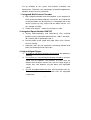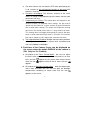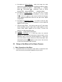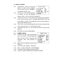
1
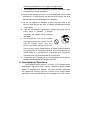
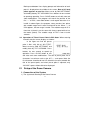
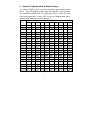
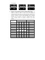
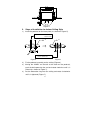
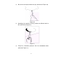
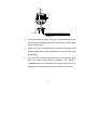
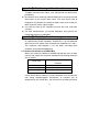
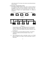
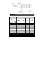
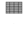
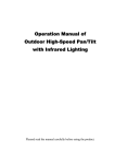
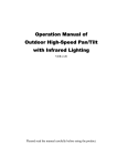
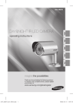
Installation and Operation Manual
for
Indoor High Speed Dome Camera
Please read the operation manual carefully
before installing and using this unit
SAFETY PRECAUTIONS
CAUTION
RISK OF ELECTRIC
SHOCK . DO NOT
OPEN !
CAUTION:
TO REDUCE THE RISK OF ELECTRICAL ,SHOCK
DO DOTOPEN COVERS .NO USER SERVICEABLE
PARTS INSIDEREFER SERVICING TO QUALIFIED
SERVICE PERSONNEL
The lighting flash with a arrowhead symbol , in an
equilateral triangle , is intended to alert the user .
There is uninsulated “dangerous voltage ” presence
near by the product ' s enclosure which may be risk of
to persons .
The exclamation point within an equilateral
triangle is intended to alert the user to reference
of the important operating and maintenance
( servicing ) instructions .
THE PRODUCT CODE MARKED ON THE BOTTOM
COVER . PLEASE FILL THE CODE IN THE FOLLOWING
BLANK . PLEASE SAVING THIS SPECIFICATION
CAREFULLY, SO THAT CHECKING.
MODEL :
PRODUCT CODE:
________________________
________________________
INDEX
1. Important Safeguards ---------------------------------------------1
2. Description of Functions ----------------------------------------------2
2.1 Integrated Multi-Protocol Decoder ---------------------------------------3
2.2 Integrated Speed-Variable PAN/TILT --------------------------------3
2.3 High Intelligent Degree -------------------------------------------------3
2.4 Functions of the Camera ------------------------------------------------4
3. Setup of the Menu of the Dome Camera -------------------------5
3.1 Basic Operation of the Menu----------------------------------------------5
3.2 Setup of the Menu--------------------------------------------------------6
3.3 Appendix to the Menu---------------------------------------------------10
4. Setup of the Dome Camera --------------------------------------------11
4.1 Connection of the System --------------------------------------------11
4.2 Setup of Coding Switch of Dome Camera ------------------------13
4.3 Setup of the Protocol and the Default Baud Rate -----------------14
4.4 Setup of the Baud Rate of Communication---------------------15
4.5 Selection of the Terminal Resistor of the Dome Camera -------16
5. The Installation of the System ---------------------------------------16
5.1 The Style of the Installation------------------------------------------16
5.2 Steps of Installation for Indoor Ceiling Style--------------------------17
5.3 Indoor embedded installation ------------------------------------18
5.4 To Ensure a Smooth and Successful Installation, You Should
--------------------------------------------------------------------------------22
6. Technical data table ---------------------------------------------------23
7. Troubleshooting ----------------------------------------------------26
Appendix
: Lighting Proof and Surge Signal Proof-------------27
: The Cleaning of Clear Down Cover--------------------28
: RS485 Bus Basic Knowledge--------------------------29
: Wi re Di a me te r a nd T ra ns miss io n Di st a nc e
Comparison Chart--------------------------------------------32
:Wire Gauge Conversion Chart-------------------------33
I. Important Safeguards
1. All the safety and operating instructions should be read before the
units is operated.
2. This unit should be operated only from the
type of power source indicated on the
marking label. If you are not sure of the
type of power supply you plan to use,
consult your appliance dealer or local
power company. For units intended to
operate from battery power or other sources, refer to operating
instructions.
3. During the course of transportation, storage and installation, the
product should be avoided from incorrect operations such as
heavy pressing, strong vibration etc., which can cause damage of
product as there are sophisticated optical and electronic devices
inside the machine.
4. Do not attempt to disassemble the camera. In order to prevent
electric shock, do not remove screws or covers. There are no
user-serviceable parts inside.
5. Always follow all electrical standards for
safety when it is in operation. Adopt the
particular power supply which is provided
with the unit. RS-485 and video signal
should keep enough distance with high voltage equipments and
cables
when
they
are
in
transmission.
Precautions
for
anti-lightning and anti-surging should be taken if necessary.
6. The product should be indoor installed and operated to avoid rain
and moisture. Do not use it in wet places. If outdoor installation is
needed, the closed protect cover should be used and it is
1
absolutely prohibited to use it in open air independently.
7. Do not operate it in case temperature, humidity and power supply
are beyond the limited stipulations.
8. Do not let the camera aim at the sun or the object with extreme light
whatsoever it is switched on or not. Do not let the camera aim at or
monitor bright and standstill object for a long time.
9. Do not use aggressive detergent to clean the main body of the
camera. Wipe dirt with dry cloth. If needed, mild detergent can be
used suitably.
10. Operate the intelligent speed dome camera with great care to
avoid shock or vibration. It operate
incorrectly, the Speed Dome could be
damaged.
11. Do not place this unit on an unstable
stand, tripod, bracket, or mount. The unit
may fall, causing serious injury to a
person and serious damage to the unit.
Use only with a stand, tripod, bracket, or mount recommended by
the manufacturer or sold with the product. Any mounting of the unit
should follow the manufacturer’s instructions and should use
mounting accessory recommended by manufacturer.
12. If necessary, use a commercial lens cleaning paper to clear the lens
windows. Gently wipe the lens window until clean.
II. Description of Functions
The intelligent dome camera is a hi-tech CCTV product which
incorporates high-clarity color camera, panoramic speed-variable
PAN/TILT, multifunctional decoder, universal character generator,
CPU processor, memory chip into a whole. It can largely reduce
connection and installation processes of components in the system,
2
rise up reliability of the system and facilitate installation and
maintenance. Therefore it has advantages of beautiful appearance,
compact structure and easy operation.
1. Integrated Multi-Protocol Decoder
a. With integrated decoder and multi-protocol, it can integrate 16
kinds of communication protocols in maximum. As its baud rate
of communication can be adjusted, it is compatible with many
normal systems by easy setup inside the dome camera, so it
has stronger versatility.
b. RS485 serial control: addresses of camera 1-1023.
2. Integrated Speed-Variable PAN/TILT
a. Turning 360ºhorizontally and continuously with unlimited
positions and an adjustable speed from 0.2 - 300º/s; turning 0 90º vertically with a speed up to 120 °/s.
b. Running stably at low speed with super lower noise. Pictures
have no shaking.
c. Automatic 180º flip and panoramic monitoring without blind
point, the location precision up to ±0.1°.
3. High Intelligent Degree
a. As much as 128 preset positions can be preset with powerless
memory.
b. The camera can scan horizontally between two points and scan
speed can be modified. The positions of linear scan are
optional and the dome camera can scan the range larger or
smaller than 180° between any two points with adjustable
speed;
c. Six sets of programmable tour locus with 16 position each set.
The running speed and the detention time are adjustable
respectively;
3
d. The dome camera can simulate the PTZ route operated by you
in 40 seconds by the self-learning function of the locus with
powerless memory;
e. Character Overlapping. The humane structure of the menu
makes all setups and programming of the dome camera more
convenient and easy.
f.
Proportional pan function. The speed dome will depend on the
amount of zoom. At telephoto zoom settings, the pan and tilt
speeds will be slower for a given amount of joystick deflection
than at wide zoom settings. This keeps the image from moving
too fast on the monitor when there is a large amount of zoom.
This slowing does not happen when going to a preset, but does
occur in turbo mode when high zoom is selected. The minimum
pan and tilt speeds are 0.1 degree per second at full zoom.
g. The Integrated Multi-Protocol. Multiple communication protocols
are integrated inside the dome camera with selectable baud
rate from 2400 bps to 9200 bps.
4. Functions of the Camera (icons can be displayed on
the screen when the option DISPLAY of the camera is
ON,
,Only for 18× Camera)
a. Description of the Focus Control Mode: the user can adjust
the focus of the camera manually. When the camera is on near
focus, the icon
appears on the screen; when on the nearest
state, the icon
appears.
appears while on the far focus, the icon
b. Description of Backlight Compensation: when the object to be
shot is dark and looks dim, the user can open the backlight
compensation according to actual need and the icon
appears on the screen.
4
c. Description of White Balance:
when the image has color
distort on the screen, the user can set different modes by orders.
There are 6modes for options:
Indoor Mode
Outdoor
Mode
Touch Mode
Automatic Trace of White
Balance ATW Manual WB-MAN
Automatic Mode.
d. Description of ZOOM Control: user can “pull near” or “push
far” the lens according to actual conditions, and the symbol
appears on the screen in which the front part
means optical multiplication while the rear part means digital
multiplication.
e. Description of Electronic Shutter: it is fixed on 1/50 sec after
initialization when the camera is switched on, and the digital 50
appears on the screen.
f. Setup of Image Effect: the camera works on OFF state under
normal condition and no image effect symbol appears on the
screen. When “B&W” appears on the screen, it means the
camera is on black and white state.
g. AE Mode: setup of Manual/Automatic.
h. Minimum illumination: It is used only when the external
brightness is extremely low. Normally the camera works on the
automatic state. In case the external brightness is lower than
1Lux, the camera can be switch to the Zero illumination state
automatically and icon
appears on the screen. You can also
set the Zero illumination state manually.
III. Setup of the Menu of the Dome Camera
1. Basic Operation of the Menu
1.1
Call preset 95 or 64 or call preset 1 twice within 4 seconds to enter
the main menu by the control keyboard or by the matrix.
5
1.2
When the menu is displayed on the screen, operate “TILT UP”,
“TILT DOWN” to move the cursor to the option to be set, operate
“PAN LEFT”, “PAN RIGHT” to modify the content or the order to
enter this option.
1.3
Keep the joystick in one direction for over 1 second to speed up
operation.
1.4
All setups on the menu couldn’t be lost even power failure
happens.
1.5
Special utilizations can be seen on the descriptions of functions of
the menu in detail.
2. Setup of the Menu
2.1
2.1.1
MAIN MENU
DISPLAY SETUP: to enter the submenu
of display of the screen by which ID
display, title display of preset point and
display of camera screen can be set.
2.1.2
CAMERA SETUP: to enter the submenu
of setup of normal data of camera.
2.1.3
CONTROL SETUP: to enter the submenu of setup of control
data over the dome camera.
2.1.4
CAMERA MASK SET: to enter the submenu of setup of mask
function of camera.
2.1.5
PROGRAM: to enter the setup of enhanced function of dome
camera.
2.1.6
PAL CAMERA: PAL/NTSC switching to suit the camera.
2.1.7
CAM DEFAULT SET: to reset default setup of camera.
2.1.8
DOME RESET: to reset the dome camera.
2.1.9
EXIT: to quit the main menu.
6
2.2 DISPLAY SETUP
2.2.1
ID DISPLAY: when it is set at ON,
address of dome camera appears
on the screen such as “CAM 001”.
The default setting is ON.
2.2.2
ID POS: to set the display position
of address on one of following
corners: TOP-L, TOP-R, BOTT-R and BOTT-L.
2.2.3
TITLE DIS: when it is set at ON, the title of preset point appears
on the left of screen such as "NO.001 ABCDEFGH” when the
preset point is called. The modification of title of preset point is
set on PROGRAM op ti on.
2.2.4
TITLE POS: to set the display position of title of preset point from
Line 1 to Line 10. Line 1 is at the top of screen.
2.2.5
CAM DISPLAY: when it is set at ON, the camera screen will be
opened.
2.2.6
2.3
2.3.1
RETURN: to return to MAIN MENU.
CAMERA SETUP
SLOW SHUTTER: frame accumulation
with two options Manual/Automatic.
When camera screen is opened under
automatic state, ASS displays on
screen.
2.3.2
BACK LIGHT: backlight compensation
ON/OFF.
2.3.3
ICR SHOT: low shooting,ON/AUTO
2.3.4
IRIS: setup of automatic iris AUTO/MANU.
2.3.5
D-ZOOM: setup of digital zooming ON/OFF.
2.3.6
FOCUS: setup of automatic focusing AUTO/ MANU.
7
2.3.7
WB SET: setup of white balance. ATW / INDOOR / OUTDOOR /
ONEPUSH / AUTO / MANU
2.3.8
MENU OF CAM: blank
2.3.9
RETURN: return to MAIN MENU.
2.4
2.4.1
CONTROL SETUP
AUTO FLIP:180° automatic flip of
dome camera ON/OFF.
2.4.2
ALARM: ALARM ON/OFF switch
2.4.3
PRESET PIC: NOP
2.4.4
HOME OPTION: enter the submenu
of automatic home function.
2.4.4.1 AUTO HOME: when it is set at ON,
home function is available, namely, the dome camera will return
HOME if user has no action in a period of time. The dome
camera shall not return HOME if it is on tour state. If no HOME is
needed when the dome camera is stopped, set the option at
OFF.
2.4.4.2 HOME POS: HOME means return home. For example to set
one scene as HOME, call the scene first and set it as preset
point, then call out the menu to enter into this submenu, change
figures after HOME POS into 5. If automatic HOME function is
needed, do not forget to set AUTO HOME at ON. This option
display 1—50/RESTORE/PATROL1 ; 1—50 means preset
position from 1 to 50; RESTORE means return back to before
state (manual control); PATROL1 means run the first patrol.
2.4.4.3 DWELL TIME: to set the time of automatic HOME, which means
the camera shall return HOME if it is not controlled in a period of
time which can be from 1 to 99 minutes.
2.4.4.4 RETURN: return to the menu one level higher.
2.4.5
RETURN: return to MAIN MENU.
8
2.5
CAMERA MASK SET
2.5.1
MASK PRIVACY: ON/OFF
2.5.2
MASK SHADE: BLACK/GRAY/WHITE
2.5.3
MASK REGION: 6 or 2 privacy zone
masking.(only for part of camera)
2.5.4
2.6
2.6.1
RETURN: return to Main Menu.
PROGRAM OPTIONS
AUTO PAN START POS: To set start position of auto scan
between two points. To move the dome camera by joystick after
entering and to return by CLOSE button.
2.6.2
AUTO PAN END POS: To set end position of auto scan between
two points. To move the holder by joystick after entering and to
return by CLOSE button.
2.6.3
RUN AUTO PAN: Auto scan function between two points. First of
all, you must set the start position and the end position of auto
scan. If the start position is just the end position, it means 360°
scan. The speed of auto scan has six grades: FAST / NORMAL /
SLOW / -FAST / -NORMAL / -SLOW in which the first three
grades are scan less than 180° while the later three grades
larger than 180°. Adjust speed by PAN LEFT/PAN RIGHT, and
operate and exit by OPEN button. The start position and the end
position of auto scan are set by options 1 and 2 in this submenu.
2.6.4
SET TITLE: to edit titles of preset position. Only previous 63
preset points have their titles. Select no. of preset position by
PAN LEFT/PAN RIGHT, enter into edit by OPEN button and exit
edit by CLOSE button. Operations under edit state can be seen
later.
2.6.5
SET PATROL: to edit data for multi-points patrol. Select no. of
patrol by PAN LEFT/PAN RIGHT,
9
enter into edit by OPEN
button and exit edit by CLOSE button.
Operations under edit state can be
seen later.
2.6.6
RUN PATROL: to run multi-points
patrol function. Select no. of patrol by
PAN LEFT/PAN RIGHT, run and exit by
OPEN button.
2.6.7
RECORD PATTERN: This pattern can
consist of any standard pan and tilt or lens command. Preset, flip,
digital zoom, proportional pan, and turbo are not allowed in a
pattern. The pattern length is 40 seconds in maximum. To return
when 40 seconds expire or by push CLOSE button.
2.6.8
RUN PATTERN: to self-learn loci of tour. To exit the menu after
running or to stop running by joystick.
2.6.9
RETURN: return to Main Menu.
3. Appendix to the Menu
3.1
Operation of Edit State of Multi-Points Patrol. When entering
into edit state the screen displays as follows:
NO – Serial No. of patrol position
POS – No. of preset position
SP – leaving speed
TM – dwelling time
After entering into edit area, screen
shows as follows:
Edit Area, data of 2 patrol position
appears on one line.
SEQ:01 – It means the set No.1 patrol
CLOSE: EXIT – Push CLOSE to exit
edit state
10
Both top and bottom lines display prompt and information of each
patrol is displayed on the middle of the screen. Data of 2 Patrol
points appears on one line. Move cursor by PAN LEFT/RIGHT
and modify data by TILT UP/DOWN. Press buttons for one second
to speed up operation. Press CLOSE button to exit edit state and
store modifications. The program will search the position of the
first “---” of POS, store dada before it and regard data after it as
invalid. In above figure, the program stores previous four points
with settable range from 1 to 63 and from 65 to 128. When “---” of
POS appears, the tour range is ended. The settable range of SP is
from 0 to 8 (0 and 1 are the same with fastest speed while 8 has
the lowest speed). The settable range of TM is from 0 to 99
seconds.
3.2 Operation of Title of Preset Point in Edit State. When entering
into edit state the screen displays as follows:
In the figure we find the preset
point is No.1 with title of “NO TITLE”.
Move cursor by PAN LEFT/RIGHT and
modify data by TILT UP/DOWN. Press
buttons for one second to speed up
operation. Press CLOSE button to exit
edit state and store modifications. The title of preset point has 8
characters in maximum such as 0-9, A-Z, +, - and space. Note: the
first character should be 0-9 or A-Z, otherwise it means to delete the
title of the preset point, and when preset point is adjusted, only
“NO.XXX” spears without title to be displayed.
IV.
Setup of the Dome Camera
1. Connection of the System
1) The Systematic Drawing of the Dome Camera
11
C
Monitor
Power IN
AC24 V
OUT
Power IN
VIDEO
OUT
V
RS-485
Power Adapter
Multiplexer
Matrix
Speed Dome
RS-485
Protocol Adapter
RS- 485
BSW
BSW
AD Matrix
RS-485
RS- 485
Code Converter
Protocol Adapter
RS 232
Philips Matrix
Figure 1
2) Address / Protocol Coding Switch Drawing
SW 1
SW2
3 2 1
ON
ON
JP
1
120Ω terminal resistor is
connected on RS485 Bus
2
3
4
5
6
1
2
3
4
3 2 1
JP
120Ω terminal resistor is
connected on RS485 Bus
Vertical view
5
6 7
8
9 10
Protocol Select Speed Dome Address Select
SW2
3 2 1
SW1
JP
Connect or Pi n
Figure 2
12
2. Setup of Coding Switch of Dome Camera.
As shown in Figure 2, SW1 is used to set address of the dome camera
from 1 – 1023. The coding switches from DIP-10 to DIP-1 are equivalent
to a 10-bit binary digital. DIP-10 is MSB while DIP-1 is LSB. The state
“ON” of each bit means 1 while “OFF” means 0. Following table shows
states of coding switches of some addresses.
Dome
States of Coding Switches
Address
DIP-1
DIP-2
DIP-3
DIP-4
DIP-5
DIP-6
DIP-7
DIP-8
DIP-9
DIP-10
1
ON
OFF
OFF
OFF
OFF
OFF
OFF
OFF
OFF
OFF
2
OFF
ON
OFF
OFF
OFF
OFF
OFF
OFF
OFF
OFF
3
ON
ON
OFF
OFF
OFF
OFF
OFF
OFF
OFF
OFF
4
OFF
OFF
ON
OFF
OFF
OFF
OFF
OFF
OFF
OFF
5
ON
OFF
ON
OFF
OFF
OFF
OFF
OFF
OFF
OFF
6
OFF
ON
ON
OFF
OFF
OFF
OFF
OFF
OFF
7
ON
ON
ON
OFF
OFF
OFF
OFF
OFF
OFF
OFF
8
OFF
OFF
OFF
ON
OFF
OFF
OFF
OFF
OFF
OFF
9
ON
OFF
OFF
ON
OFF
OFF
OFF
OFF
OFF
OFF
10
OFF
ON
OFF
ON
OFF
OFF
OFF
OFF
OFF
OFF
11
ON
ON
OFF
ON
OFF
OFF
OFF
OFF
OFF
OFF
12
OFF
OFF
ON
ON
OFF
OFF
OFF
OFF
OFF
OFF
13
ON
OFF
ON
ON
OFF
OFF
OFF
OFF
OFF
OFF
14
OFF
ON
ON
ON
OFF
OFF
OFF
OFF
OFF
OFF
15
ON
ON
ON
ON
OFF
OFF
OFF
OFF
OFF
OFF
16
OFF
OFF
OFF
OFF
ON
OFF
OFF
OFF
OFF
OFF
17
ON
OFF
OFF
OFF
ON
OFF
OFF
OFF
OFF
OFF
18
OFF
ON
OFF
OFF
ON
OFF
OFF
OFF
OFF
OFF
…
…
…
…
…
…
…
…
…
…
…
1023
ON
ON
ON
ON
ON
ON
ON
ON
ON
ON
Table 1
13
For Example:
ON
ON
1
2
3
4
5
6 7
8
9 10
ON
1
2
3
4
5
6 7
8
9 10
ON
ON
1
2
3
4
5
6 7
8
1
3
4
5
6 7
8
9 10
ON
1
9 10
Speed Dome Address= 4
2
Speed Dome Address = 3
Speed Dome Address=2
Speed Dome Address=1
2
3
4
5
6 7
8
1
9 10
Speed Dome Address=18
2
3 4
5
6 7
8
9
10
Speed Dome Address=1023
3. Setup of the Protocol and the Default Baud Rate. As
shown in Figure 2, SW2 is used to set the protocol of
communication and the baud rate used by the dome camera. DIP-4
to DIP-1 of SW2 is used to select protocols and 16 different
protocols can be selected in maximum. Following table shows
states of coding switches of protocols selected by the dome
camera.
DIP status
Protocols
Normal Baud Rate
DIP-1
DIP-2
DIP-3
DIP-4
DIP-5
DIP-6
SAMSUNG
ON
OFF
OFF
OFF
OFF
ON
B01
ON
OFF
OFF
OFF
OFF
ON
NEON
ON
OFF
OFF
OFF
OFF
ON
Santachi
OFF
ON
OFF
OFF
OFF
ON
PELCO-D
ON
ON
OFF
OFF
OFF
OFF
OFF
OFF
ON
OFF
ON
OFF
OFF
ON
PELCO-P/4800
PELCO-P/9600
PANASONIC
ON
OFF
ON
OFF
OFF
ON
Longcomity
OFF
ON
ON
OFF
OFF
ON
HUNDA600
ON
ON
ON
OFF
OFF
ON
LILIN
OFF
OFF
OFF
ON
OFF
ON
VICON
ON
OFF
OFF
ON
ON
OFF
14
MOLYNX
OFF
ON
OFF
ON
OFF
ON
KALATEL
ON
ON
OFF
ON
ON
OFF
VCL
OFF
OFF
ON
ON
OFF
ON
Reserved
ON
OFF
ON
ON
OFF
ON
ALEC
OFF
ON
ON
ON
OFF
ON
Ultrak
ON
ON
ON
ON
OFF
ON
Table 2
Some protocols and the states of the coding switches of normal
baud rate of these protocols are shown as follows:
NEON/9600 Bps
ON
PANASONIC / 9600 Bps
1
2
3
4
5
6
ON
KALATEL / 4800 Bps
PELCO -D /2400Bps
1
2
3
4
5
ON
1
2
3
4
5
6
1
2
3
4
5
6
1
2
3
4
5
6
1
2
3
4
5
6
ON
6
ON
PELCO- P/4800 Bps
1
2
3
4
5
ALEC / 9600Bps
6
ON
PELCO - P / 9600Bps
ON
ON
Ultrak/ 9600 Bps
1
2
3
4
5
6
4. Setup of the Baud Rate of Communication. As shown in
Figure 2, SW2 is used to set the protocol of communication and the
baud rate used by the dome camera. DIP-6 and DIP-5 of SW2 are
used to select the baud rate of communication and 4 different baud
rates can be selected in maximum. If the controller adopts
non-standard baud rate, you can adjust it to be identical with that of
the main machine as per the following table.
Baud Rate of
Communication
Setup of Baud Rate
DIP-1
DIP-2
DIP-5
DIP-6
2400 bps
OFF
OFF
4800 bps
ON
OFF
15
DIP-3
DIP-4
9600 bps
OFF
ON
19200 bps
ON
ON
Table 3
5. Selection of the Terminal Resistor of the Dome Camera.
As shown in Figure 2, JP1 is the select switch of the 120 Ω terminal
resistor on the bus RS485, on which only one terminal resistor of
the dome camera at the farthest end can be connected, while the
terminal resistors of other devices should be opened.
. The Installation of the System
1. The Style of the Installation
1) Dimension of the Product
205
140
a) Indoor Ceiling Installation
Φ137
Φ 195
b)
Figure 3
Indoor Embedded Installation
16
125
Ф 137
Figure 4
2.
Steps of Installation for Indoor Ceiling Style
1)
Install the pedestal on the base plate (as shown on Figure 5).
Q6 : M 2. 5 × 5 round head
black screw
A
B
D
Q3 : M 4 × 1. 25 ″stainless
screw steel wood
Figure 5
Figure 6
2)
Fix the pedestal assembly on the ceiling (Figure 6).
3)
Aiming the “MARK” on the ball at the notch on the pedestal,
push the ball upward to the end and rotate clockwise until it is
clicked (as shown on Figure 7).
4)
Put the decoration ring near the ceiling and rotate it clockwise
until it is tightened (Figure 7).
17
5)
Figure 8 shows the system is installed.
6)
The names of some parts are as follows:
A:Base Plate B:Pedestal C:Decoration Ring
Assembly
D : Pedestal
To prevent the dome camera
from being taken away at
random, add the screw avoid
theft
.
Mark
C
Figure 7
Figure 8
3. Indoor embedded installation
Notice: The thickness of the ceiling to install speed dome
must be ≤ 1.65 inch (4.2 cm) and ≥ 0.38 inch (0. 8cm).
Notice: The ceiling should withstand 4 times the load of the
speed dome weight.
1) It has the drill map in embedded bracket,tip the black parts of
double paper, the central of drill map have a red spot, which is
central spot (reference to Figure 9)
Figure 9
18
2)
Base on the red spot to draw the sign (reference to Figure 10)
3)
Figure 10
According the material of ceiling, choice the different tools to
drill (reference to Figure 11)
Figure 11
4)
Fixup the “installation pedestal” with the embedded mount
(reference Figure 12)
19
Pedestal
Q1A :M 4×12 countersunk head screw ( 3 pcs )
Figure 12
5)
For easy installation, adjust the three swing mounting clips to
let the distance between the clips and the flange a little longer
than ceiling thickness
6)
Swing the three mounting clips to adhere to back box wall.
Place the back box inside the ceiling hole. Let the flange cling
to the ceiling
7)
Turn the three mounting clip bolts to let the mounting clips
press the ceiling and swing out gradually. The ceiling is
clamped between the mounting clips and the flange, thus the
back box is secured above the ceiling. (Refer to Picture 13)
20
Indoor drop celing
installation bracket
Swing mounting Clip
Ceiling
Flange
Decoration Ring
Figure 13
1)
See labeling of the system line for mains lead connection
(Figure 14).
RED CONNECTOR
( POWER IN)
RED LINE( AC24 V IN)
BLACK LINE( AC24 V IN)
ORANGELINE (RS485+)
YELLOWLINE( RS 485- )
BLACK
( RS485 CONTROL IN )
VIDEO OUT
Figure 14
2)
Insert attachment plug in aluminum alloy into socket D2 (Figure
15-1). According the fig of D3 to connection. As show of fig15-1,
when dome identify the alarm signal, that will set according the
program immediately, then startup camera, switching the image
of alarm field to main monitor. Surveillance the alarm preset,
then record it in time. Fig15-2 is connection of alarm control.
Input of alarm: Input signal of switch type, any other
input signal will damage dome. When multi-channel with
alarm signal, dome will respond one by one, the removed
time is two sec.
Once the dome have alarm input, dome will not
respond“
“ scanning”
”、“patrol”
”、“remember
tracking”
” etc
“
“
function.
21
D3
ALM-4 : Channel 4
ALM-3 : Channel 3
ALM-2 : Channel 2
ALM-1 : Channel 1
GND : Common
VIDEO OUT
VIDEO GND
collector alarm input:1
collector alarm input:2
1:AC24 V IN
collector alarm input:3
2:AC24 V IN
collector alarm input:4
collector alarm input:5
1
3:RS485 +
1
COM : Common collector alarm output:6
NC : Close collector alarm output:7
NO: Open collector alarm output:8
4:RS485 -
D2 : connect fan/heater
(AC 24V)
Figure 15-1
Alarm input
ALM-1
ALM - 2 ALM - 3 ALM - 4
Alarm output
No.1 - channel alarm
No.2 - channel alarm
No.3 - channel alarm
No.4 - channel alarm
NO
NC
COM
GND
ALM- 1
A LM- 2
ALM- 4
A LM- 3
D3
was activation, then call No .
was activation, then call No .
was activation, then call No .
was activation, then call No .
29
30
31
32
preset
preset
preset
preset
Presetting the preset of NO
. 29 、30 、31、
32 ,
then the alarm could respond
.
Figure 15-2
4.
To Ensure a Smooth and Successful Installation, You Should:
1、 Have electrical work to comply with latest national electrical
code, national fire code, and all applicable local codes and
ordinances.
2、 Coordinate with other trades to avoid interference.
3、 Verify existing conditions on the site and coordinate with owner
side to ensure necessary utilities available.
4、 Copy all related plans, specifications, shop drawings and
attachments to schedule and coordinate related work.
5、 Thoroughly review the project to ensure that all jobs should meet
22
or exceed the above requirements. Contact with the CCTV
Project Coordinator to draw attention in case alleged
discrepancies occur.
6. Technical data table
1. High speed Dome cameras technology
Power supply
Power consumption
AC24V 50/60Hz
Indoor dome:15W
Outdoor dome:35W
Sync system
Internal/External selectable
Preset
128 presets
Auto tour
6
Pattern
40s
Alarm
4 channels input & 1 channel output
Privacy masking
6 (some model only)
Zoom-rotation
Interaction
Control speed auto adjust according to the
focus length
Auto flip
Rotate 180 when camera tilts to the
vertical position
Auto pan scan
360°Programmable
Pan speed
0° -- 300°/s
Pan rotation range
360°continues
Title range
Tilt 90°
Tilt speed
0° -- 120°/s
Control mode
RS485
Baud Rate
2400/4800/9600/19200 bps
Fan & heater
Fan & heater auto-start (only outdoor
dome)
Environment temp
Indoor dome:0℃ — +40℃
Outdoor dome:–35℃ -- +55℃
Table 4
23
3. Camera Optional data table
Mode
Sync mode
16×
18×
EX-480AP
22×
Color
Day/Night
Color
Internal
23×
Day/Night Day/Night
Internal/External
Image
Inductor
1/4″Color CCD
Scanning
system
2:1 interlacing
Resolution
Effecti PAN
ve
Pixels NTSC
Sensitivity
>470TVL
≥480TVL
470,000
pixels
752×582(440K)
758×592( 795×596(
450K)
470K)
440,000
pixels
768×494(380K)
758×504( 811×508(
380K)
410K)
1Lux(F1.6 1Lux / 0.2LuxF1.
)
0.01Lux
6 1/3s)
Iris
Auto/ Manual
Focus
Auto/ Manual
Zoom Rate
Angel of view
1Lux /
0.01Lux
1Lux /
0.01Lux
16×
optical
18×
optical
22×
optical
23×
optical
27×
optical
f=3.9 to
63 mm
f=4.1 to
73.8 mm
f=4 to 88
mm
f=3.6 to
82.8 mm
f=3.6 to
98 mm
Wide: 47° Wide: 48° Wide: 47° Wide: 54°
TELE: 3° TELE:2.7° TELE:2.2° TELE:2.5°
B.L
compensation
Auto/ Manual
White balance
Auto/ Manual
Gain Control
Auto/ Manual
S/N
27×
>46dB
≥50dB
Video output
1.0±0.2Vp-p
Table 5
24
7. Troubleshooting
Problems
Possible Causes
Remedies
No action when
power is
switched on
Power supply fault
Replace
Bad connection of the power
Correct
Transformer damaged
Replace
Mechanical failure
Repair
Camera inclined
Reinstall
Power supply not enough
Replace
Video signal fault
Reinstall
Bad connection of the video
Press to connect well
Camera damaged
Replace
RS485 bus bad connection
Check the RS485
connection
Dome ID setup is wrong
Reselect
Protocol setup is wrong
Reset and Switch
ON again
Bad connection of the video
Press to connect well
Power supply not enough
Replace
Self check error
Switch ON again
Bad connection of control
Press to connect
well
Bad control of matrix
Switch ON again
Abnormal
self-check.
Images with
motor noise
Normal
self-check but
no images
Normal
self-check but
out of control
Vague image
Dome camera
out of control
Table 6
Appendix Ⅰ: Lightning Proof and Surge Signal Proof
The product adopts TVS lightning proof technology to prevent from
damage by lightning strike below 1500 W and impulse signals such
as surge; but it is also necessary to abide by the following
25
precautions to ensure electrical safety based on practical
circumstances:
Keep the communication cables at least 50 meters away from high
voltage equipment or cables.
Make outdoor cable laying-out under eaves as possible as you can.
In open area shield cables in steel tube and conduct a single point
ground to the tube. Trolley wire is forbidden in such circumstances.
In strong thunderstorm or high faradic zone (such as high voltage
transformer substation), extra strong lightning proof equipment must
be installed.
Take the building lightning proof requirements into account to
design the lightning proof and grounding of outdoor equipment and
cable laying-out in accordance with the national and industrial
standards.
The system must be grounded with equal potentials. The earth
ground connection must satisfy the anti-interference and electrical
safety requirements and must not short circuited with high voltage
electricity net. When the system is grounded separately, the
resistance of down conductor should be ≤ 4Ω and the sectional
area of down conductor should be ≤25 mm2 (refer to Picture 16)
Figure 16
26
Appendix Ⅱ: The Cleaning of Clear Down Cover
To obtain constant clear videos, user should clean the down cover
periodically.
Be cautious when cleaning. Hold the down cover ring only to avoid
direct touch to the acrylic down cover. The acid sweat mark of
fingerprint will corrode the coating of down cover and scratch on
down cover will cause vague images.
Use soft dry cloth or the substitute to clean the inner and outer
surfaces.
For hard contamination, use neutral detergent. Any cleanser for
high grade furniture is applicable.
Appendix Ⅲ: RS485 Bus Basic Knowledge
1. Characteristics of RS485 Bus
As specified by RS485 standards, RS485 Bus is of half-duplexed
data transmission cables with characteristic impedance as 120Ω.
The maximum load capacity is 32 unit loads (including main
controller and controlled equipment).
2. Transmission distances of RS485 Bus
When user selects the 0.56mm (24AWG) twisted pair wires as data
transmission cable, the maximum theoretical transmitting distances
are as follows:
Maximum Transmitting
Baud Rate
Distance
2400 Bps
1800m
4800 Bps
1200m
9600Bps
800m
Table 7
If user selects thinner cables, or installs the dome in an environment
with strong electromagnetic interference, or connects lots of
equipment to the RS485 Bus, the maximum transmitting distance
27
will be decreased. To increase the maximum transmitting distance,
do the contrary.
3. Connection and termination resistor
The RS485 standards require a daisy-chain connection between
the equipment. There must be termination resistors with 120Ω
impedance at both ends of the connection (refer to Figure 17).
Please refer to Figure 18 for simple connection. “D” should not
exceed 7m.
. . . . .
120Ω
1#
2#
3#
4#
120Ω
32#
Figure 17
A+
. . . . .
BD
A+
B. . . . .
120Ω
Main controller
1)
2)
1#
2#
3#
120Ω
31#
Figure 18
The connection of 120Ω termination resistor: The termination
resistor is ready on the Protocol PCB. There are two kinds of
connection. Refer to the Protocol PCB jumper setting form (refer
to Picture 2,3).
In the Picture it is the factory default connection. The jumper is
seated on Pin2&Pin3 and the termination resistor is not
connected.
when connecting the 120Ω termination resistor, user should
plug the jumper on Pin1&Pin2. and the termination resistor is
connected.
28
4. Problems in practical connection
In some circumstances user adopts a star configuration in practical
connection. The termination resistors must be connected to the two
equipment that are farthest away from each other, such as
equipment 1# and 15# in Picture 34. As the star configuration is not
in conformity with the requirements of RS485 standards, problems
such as signal reflections, lower anti-interference performance arise
when the cables are long in the connection. The reliability of control
signals is decreased with the phenomena that the dome does not
respond to or just responds at intervals to the controller, or does
continuous operation without stop (refer to Figure 19).
Figure 19
In such circumstances the factory recommends the usage of
DR-HB16 RS485 distributor. The distributor can change the star
configuration connection to the mode of connection stipulated in the
RS485 standards. The new connection achieves reliable data
transmission (refer to Figure 20).
29
Figure 20
Appendix Ⅳ:
Wire Diameter and Transmission Distance Comparison Chart
Wire diameter (mm)
Transmission
Distance
Pow er
0.8000
1.000
1.250
2.000
feet(m)
[ VA]
10
283(86) 451(137) 716(218) 1811(551)
20
141(42) 225(68)
358(109) 905(275)
30
94(28)
150(45)
238(72)
603(183)
40
70(21)
112(34)
179(54)
452(137)
50
56(17)
90(27)
143(43)
362(110)
60
47(14)
75(22)
119(36)
301(91)
70
40(12)
64(19)
102(31)
258(78)
80
35(10)
56(17)
89(27)
226(68)
90
31(9)
50(15)
79(24)
201(61)
100
28(8)
45(13)
71(21)
181(55)
110
25(7)
41(12)
65(19)
164(49)
120
23(7)
37(11)
59(17)
150(45)
30
130
21(6)
34(10)
55(16)
139(42)
140
20(6)
32(9)
51(15)
129(39)
150
18(5)
30(9)
47(14)
120(36)
160
17(5)
28(8)
44(13)
113(34)
170
16(4)
26(7)
42(12)
106(32)
180
15(4)
25(7)
39(11)
100(30)
190
14(4)
23(7)
37(11)
95(28)
200
14(4)
22(6)
35(10)
90(27)
Table 8
Appendix Ⅴ : Wire Gauge Conversion Chart
Bare wire
diameter
metric size
(mm)
AWG
(Approximate)
SWG
(Approximate)
Bare wire
cross
sectional area
(mm2)
0.050
43
47
0.00196
0.060
42
46
0.00283
0.070
41
45
0.00385
0.080
40
44
0.00503
0.090
39
43
0.00636
0.100
38
42
0.00785
0.110
37
41
0.00950
0.130
36
39
0.01327
0.140
35
0.160
34
0.180
33
0.200
32
0.230
31
0.250
30
33
0.04909
0.290
29
31
0.06605
0.01539
37
0.02011
0.02545
35
0.03142
0.04115
31
0.330
28
30
0.08553
0.350
27
29
0.09621
0.400
26
28
0.1237
0.450
25
0.560
24
24
0.2463
0.600
23
23
0.2827
0.710
22
22
0.3958
0.750
21
0.800
20
21
0.5027
0.900
19
20
0.6362
1.000
18
19
0.7854
1.250
16
18
1.2266
1.500
15
2.000
12
0.1602
0.4417
1.7665
14
3.1420
2.500
4.9080
3.000
7.0683
Table 9
32
CCTV
SYSTEM