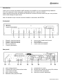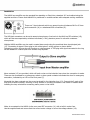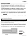
1
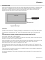
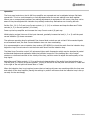
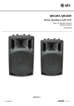
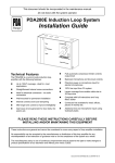
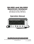
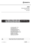
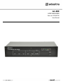
LA-600 LOOP AMPLIFIER Item ref: 952.867UK User Manual Caution: Please read this manual carefully before operating Damage caused by misuse is not covered by the warranty SAFETY SYMBOL AND MESSAGE CONVENTIONS CAUTION RISK OF ELECTRIC SHOCK DO NOT OPEN AVIS RISQUE DE CHOC ELECTRIQUE NE PAS OUVRIR This symbol indicates that dangerous voltage constituting a risk of electric shock is present within this unit This symbol indicates that there are important operating and maintenance instructions in the literature accompanying this unit. SAFETY NOTICE 1. 2. 3. 4. 5. 6. 7. 8. 9. 10. 11. 12. 13. 14. 15. 16. Prior to use, read through this manual Keep the manual in good condition Pay attention to safety warnings Observe all operating requirements Do not use the device near water or wet areas For cleaning, only use a lint-free, dry cloth Install according to the specifications Place away from heat sources or heating appliances Use mains lead provided and avoid damage to cable or connectors Unplug power from mains during stormy weather or if unused for long periods In case of malfunction, water ingress or other damage, consult qualified service personnel Do not place in damp areas or near liquids or moisture. Do not spill liquids on the housing Please pay attention to warning symbols during transit and placement Terminals marked with the symbol are HAZARDOUS LIVE and should only be connected by qualified personnel Ensure that the apparatus is connected to a mains socket with a protective EARTH connection Ensure correct operation of the mains switch Warning To prevent the risk of fire or electric shock, do not expose any components to rain or moisture. If liquids are spilled on the casing, stop using immediately, allow unit to dry out and have checked by qualified personnel before further use. Avoid impact, extreme pressure or heavy vibration to the case No user serviceable parts inside – Do not open the case – refer all servicing to qualified service personnel. Safety Check for correct mains voltage and condition of IEC lead before connecting to a power outlet Use insulated loop wire, ensuring the correct gauge for the loop distance required Do not allow any foreign objects to enter the case or through the ventilation grilles Placement Use the mounting ears supplied when installing into a 19” rack For rack-mounting, ensure adequate support for the weight of the amplifier Ensure adequate air-flow and do not cover cooling vents at the front and rear of the amplifier Ensure adequate access to controls and connections Cleaning Use a soft cloth with a neutral detergent to clean the casing as required Use a vacuum cleaner to clear ventilation grilles of any dust or debris build-ups Do not use strong solvents for cleaning the unit 952.867UKUser Manual Introduction Thank you for choosing the Adastra LA600 induction loop amplifier for your assisted hearing installation. This unit is designed to offer high quality, dependable service for areas up to 600m². Please read this manual fully and follow the instructions to achieve the best results with your new purchase and to avoid damage through misuse. Note: All induction loops in the UK should be installed in accordance with BS7594. Front panel 1. 2. 3. 4. 5. Channel 1 input level control Channel 2 input level control Channel 3 input level control Bass EQ adjustment Treble EQ adjustment 6. 7. 8. 9. Loop current (master level) control Siren indicator Loop current level indicator Power switch and indicator 15. 16. 17. 18. Unbalanced RCA inputs Mic/line level, phantom & priority DIP switches Combined Slave input/output Metal loss correction adjustment Rear panel 10. 11. 12. 13. 14. Mains voltage selector Combined IEC mains inlet and fuse holder Loop output terminals Alarm contact terminals Balanced combo jack/XLR inputs 952.867UKUser Manual Installation The LA600 loop amplifier can be operated free-standing or fitted into a standard 19” rack cabinet using the supplied rack ears. Ensure that theLA600 is positioned on a stable surface with adequate cooling ventilation. There are 3 input channels which can accept inputs via balanced XLR or 6.3mm jack connection (14) or unbalanced RCA connection(15). The XLR/jack connectors can be set to accept microphone or line level via the Mic/Line DIP switches (16), which are also accompanied by switches to activate (+20V) phantom power for use with condenser microphones. Multiple LA600 amplifiers can be used in master/slave mode using the combined slave input/output jack (17). Connecting a stereo 6.3mm plug to this socket gives 2 wiring options as shown below. Connecting a mono 6.3mm plug will function as a slave output. A TRS plug with signal connected to the ring will be needed for a slave input from another loop amplifier. Alarm contacts (13) are provided, which will emit a siren on the induction loop when the connection is made. These can be connected to an emergency switch or alarm panel contacts to activate the siren for emergency evacuation, indicated by an LED on the front panel (7) Alongside the alarm contacts are the screw terminals for the induction loop (12). Connect the 2 ends of the loop wire to these terminals, ensuring no stray strands or shorted connections. See below for details about installing the loop wire before connecting mains power to the LA600 Mains is connected to the LA600 via the rear panel IEC connector (11) with a built-in mains fuse. Use the supplied lead and ensure that the correct mains voltage is set on the voltage selector (10). 952.867UKUser Manual Induction loop cable installation Prior to installation, it is important to check if there will be any equipment in the vicinity that may interfere with the loop’s magnetic field, such as large transformers, high power cables or substations. It is also important to ensure that no equipment will be adversely affected by the loop field, such as sensitive data or signal cables. In these cases, it may not be possible to cover some or any of the required area with an induction loop. The LA600 can cover an area up to 600m² in ideal conditions. The cable gauge will depend upon the total length of the induction loop. Usually, the loop will be installed around the perimeter of the listening area. However, there are various techniques which can be employed to build arrays to vary the shape and strength of the field. In general, calculations outlined here are based upon a perimeter installation. It is recommended to use good quality insulated pure copper cable for the induction loop. The cable gauge used will need to be determined by the total length of the cable run. The LA-600 is designed to operate with a load of between 0.2Ω and 2Ω. The following equation can be used to calculate the total cable resistance, which will show if the gauge is correct. R= Cable length (m) Cable CSA (mm²) x 0.01786Ω*mm²/m (specific resistance of Copper) So, for a cable 80m long with a Cross-Sectional Area (CSA) of 1.5mm²… R = 80/1.5 x 0.01786 = 0.9525Ω So, this gauge of wire (1.5mm²) would be OK for the 80m run because it is between 0.2Ω and 2Ω As a quick reference, refer to the table below. Cable CSA (mm²) Total Loop Length 1.0 60m max. 1.5 110m max. 2.5 200m max. 4.0 Over 200m The wire may be run in plastic conduit but not in any metal containment so as not to impair the magnetic flux. The ideal height to install the cable depends upon the width of the loop (i.e. the narrowest dimension relative to the listener). The optimum output will be achieved if the cable is installed 14% of the loop width higher or lower than the plane of listening (ear height). In practical terms, the loop is usually installed onto skirting boards, under flooring or at ceiling height so that it is unobtrusive. It is recommended to avoid varying height levels as much as possible to avoid anomalies in field strength. For irregular shaped areas or larger than 600m², multiple induction loops may be required for coverage. Connecting further LA600 amps using the Slave connection will enable multiple loops to be used together. 952.867UKUser Manual Cancellation Loops If there are areas adjacent to the loop where the magnetic field would cause problems, it is possible to avoid this by use of a “cancellation loop”, which is a narrow loop parallel to the main loop at the problem area. This loop is the opposite polarity to the main loop and causes the magnetic field to narrow along the adjacent edge of the main loop to control the spill of the loop field. Connection Connect any line sources (e.g. CD player, mp3 player) or microphones to one or more of the input channels. If a microphone is connected, select “MIC” on the DIP switches and connect via the 6.3mm jack or XLR input. If the microphone is a condenser microphone requiring phantom power, select “PHANTOM”. For standard dynamic and battery powered microphones, set the Phantom switch to “OFF” For line inputs, select “LINE” on the DIP switches. For channel 1, there is an option for “PRIORITY” over the other two channels, which will mute the output of channels 2 and 3 when there is an input to channel 1. If the loop amplifier is to be used in conjunction with a PA system with loudspeakers, connect the line or aux output from the PA system to a Line input on the loop amplifier via RCA, jack or XLR connection. Ensure that this input is set to “LINE” and Phantom is set to “OFF” Before connecting the induction loop to the amplifier, use a test meter to check the D.C. resistance in the wire. Ensure that there are no shorted or grounded points in the wire and that the total resistance is not less than 0.5Ω Twist the loop wires from where the loop ends to the amplifier terminals to avoid creating an extended loop to the area where the amplifier is situated. With the power switched off (9), connect the loop cable to the loop terminals (12) on the rear panel of the loop amplifier. 952.867UKUser Manual Operation The front panel controls on the LA-600 loop amplifier are recessed and can be adjusted using a flat blade screwdriver. This is to avoid tampering or mal-adjustment after the correct settings have been applied. Where new or unsupervised operators are making adjustments to equipment in the venue, they may not be aware if they have adjusted the induction loop settings unless they themselves are a hearing aid user. Set the Ch.1, Ch.2, Ch.3 and Loop Current controls (1, 2, 3, 6) to minimum and keep the Bass and Treble controls (4, 5) in the mid position (12 o’clock) Power up the loop amplifier and increase the Loop Current control (6) part way. Whilst playing a signal into one of the input channels, gradually increase the level (1, 2 or 3) until the peak current indicator (8) shows movement. The optimum operating level is achieved if the channel level controls are set so that if all connected signals are at maximum level, the Peak Current indicator does not show overloading. It is recommended to use an induction loop receiver (952.855UK) to check the audio from the induction loop. Adjust the Loop Current control to set the main audio level from the induction loop. The Metal Loss Correction control (18) enhances higher audio frequencies which may be absorbed by metal architectural features and appliances within the induction loop area. If the building has a lot of metal structure or reinforced concrete in the vicinity of the loop, use this control to adjust the audio quality of the loop signal. Adjust Bass and Treble controls (4, 5) to set the tonal characteristics of the audio from the induction loop. The mid point (12 o’clock) is the zero position. Turning to the left of the mid point will cut Bass or Treble and to the right of the mid point will boost Bass or Treble. When the induction loop is not required, ensure that no hearing aid users are remaining within the loop area and switch off the loop amplifier (leaving the settings in position will ensure that the induction loop is set up correctly for the next usage) 952.867UKUser Manual Specifications Power supply Fuse Area coverage Frequency response Input sensitivity : line Input sensitivity : mic Signal to noise ratio THD Dimensions Weight 110/240Vac, 50/60Hz (IEC) T2A 250V 600m² max. 50Hz - 5kHz (±3dB) -6dBu/6k Ohms -56dBu/2k Ohms 75dB (line), 60dB (mic) <1% 430 x 235 x 88mm 5.95kg Troubleshooting No power indicator when switched on Peak current indicators are not showing any signal Dead spots within induction loop field Loop field interfering with other audio equipment Siren activated Peak indicators mainly showing overload (red) Loop current is very low Poor quality audio from the loop Check mains is connected and switched on at the socket Check that the mains fuse is not blown – refer to qualified service personnel If the fuse is blown, check that the loop contacts were not shorted out Check input connections are OK and that a signal is present on the input Check that the loop is intact and connected to the amplifier properly Increase channel level controls and Loop current if necessary Check for large metal structures within the architecture close to the loop Avoid changes in height of the loop cable (running over door frames etc.) Ensure that the loop cable is twisted between the loop and the loop amplifier If necessary, form a cancellation loop to avoid affecting other equipment Ensure that the alarm contacts are not accidentally shorted out. Loop current or input levels may be too high, decrease the relevant controls Check that the loop is not shorted or grounded at any point Increase input signal, channel levels and loop current controls as needed If there are metal structures nearby, increase metal loss correction level Use Bass and Treble controls to help improve intelligibility Disposal: The “Crossed Wheelie Bin” symbol on the product means that the product is classed as Electrical or Electronic equipment and should not be disposed with other household or commercial waste at the end of its useful life. The goods must be disposed of according to your local council guidelines. Errors and omissions excepted. Copyright© 2015. AVSL Group Ltd. 952.867UKUser Manual