1
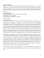
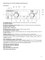
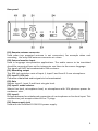
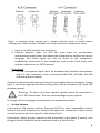
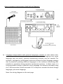
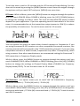
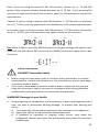
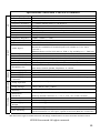
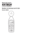
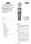
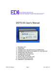
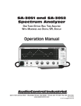
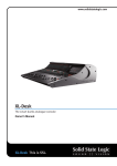
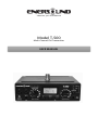
Passion for innovation Model T‐500 Multi‐Channel FM Transmitter USER MANUAL 1 T‐500 Table of Contents_________________________________________ About this Manual ………………………………………………………………….. 3 Package Contents ……………………………………………………………….….. 3 System Overview ……………………………………………………………….…... 3 Quick reference: Controls, displays and connectors ……….………. 4 ‐ 5 Front Panel ………………………………………………………………………….. 4 Rear Panel ………………………………………………………………….………… 5 Set‐up Instructions …………………………………………………………………. 6 ‐ 11 General Set‐Up Instructions ………………………………………………… 6 ‐ 8 Application Notes ……………………………………………………………….. 9 ‐ 11 a) For direct language interpretation ………………………………. 9 ‐ 10 b) For language interpretation with interpreter console …. 10‐11 Menu Setting Instructions ………………………………………………………. 11‐13 Safety Information ………………………………………………..……………….. 13‐14 Trouble Shooting …………………………………..……………………………….. 14‐15 FCC & IC Statements ………………………………………………………………. 16 Warranty Statement ………………………………………………………………. 17 Optional Accessories ……………………………………………………….……... 18 Frequency Chart …………………………………………………………………….. 18 Technical Specifications ………………………………………………………….. 19 2 About this Manual Read this user manual carefully before installing and operating your T‐500 FM transmitter. Use the product only as described to avoid accidental injury, damage or hearing impairment. Also, read safety warnings carefully. Keep this manual for future reference. If you give this product to someone else, remember to include this manual. Package Contents (1) T‐500 FM multi‐channel transmitter (72‐76 MHz) (1) ANT‐500 helical antenna (1) PS‐500 power supply with AC cord (1) User manual System Overview Thank you for choosing the Enersound T‐500 FM multichannel transmitter. This professional transmitter is designed for assistive listening and language interpretation. It wirelessly broadcasts a speaker’s voice, music or any audio signal up to 1000 ft. (305 m). The audience can use the optional R‐120 FM multichannel receiver or any other compatible FM receiver operating on the 72‐76 MHz frequency to pick up the broadcast. The T‐500 transmitter features 3 main audio inputs that allow the direct connection of virtually any analog audio source, including a 3.5 mm jack for headset microphones, an XLR & ¼ inch combination jack with a selector for dynamic microphones, condenser microphones or line‐level signals, and a RCA line auxiliary input. It also has a recording output and a 3.5 mm monitor headphone jack. For language interpretation, it has a unique integrated interpreter monitor function. This feature allows interpreters to select an external incoming audio source and utilize a headset with microphone to listen to the source language without the need of an interpreter console or external headphone amplifier. Through the headphones’ volume control, interpreters can set the desired incoming audio level and the [MUTE] button allows them to momentarily silence their microphone for coughing or sneezing. For more advanced interpreting functions, it can also be utilized with the Enersound IC‐12 multi‐channel interpreter console or with any other interpretation platform with analog audio outputs. Its LCD display allows to easily program the various useful functions, such as test tone, RF power level, display mode (frequencies or channel numbers), and channel lock. 3 Quick Reference: Controls, Displays and Connectors Front panel (1) POWER button: Press & hold for 5 seconds to turn on/ off device. (2) Power indicator (3) Front microphone mute button: Press to mute/unmute front microphone. (4) Mute indicator light (5) Mic input, 3.5mm jack (6) Main volume control: Adjusts audio output volume. (7) Headphones volume control (8) Up button: Changes channel/frequency up. During setting mode, press to modify selection. (9) Menu button: Press & hold for 6 seconds to access setting menu. (10) Down & lock button: Changes channel/frequency down. Press & hold for 5 seconds to lock/ unlock channel/frequency. During setting mode, press to modify selection. (11) Headphones output, 3.5mm jack (12) Internal/external monitor source selection switch: Set to EXT for language interpretation applications to monitor an external audio source (speech to be translated). Set to INT to monitor the broadcasted audio. (13) Internal selection indicator (14) External selection indicator (15) LCD screen (16) (17) Audio level indicators (18) Audio peak indicator 4 Rear panel (19) Remote antenna connector Used when top mounted antenna is not convenient, for example when rack mounting. Use only ONE antenna connector at a time. (20) External monitor Input Used in language interpretation applications. The audio source to be translated should be connected here so the interpreter can listen to the source language. This signal will NOT be broadcasted to FM receivers. (21) Recording output This RCA jack contains a mix of Input 1, Input 2 and front 3.5 mm microphone. (22) Input 2, RCA jack Connects unbalanced audio signals to be broadcasted. (23) Gain Adjusts Input 1, Input 2 and front mic gain level. (24) Input 1 mode selector Selects line level, microphone level, or microphone with 12V phantom power for condenser mics. (25) Input 1 Accepts balanced or unbalanced connection of a microphone or line level input. This combination jack accepts either XLR or ¼” plugs. (26) Power supply jack Used with the included PS‐500 15V power supply. 5 Set‐up Instructions General Set‐up Instructions: Unpack the transmitter Remove outer packaging and plastic cover. Inspect for physical damage and immediately report any issues. Position the unit Position the transmitter near the audio source (sound system, mixer, interpreter desk, etc.), away from metallic objects that might interfere with the antenna. Connect the antenna For tabletop use, screw in the antenna connector onto the transmitter top antenna connector. Alternatively, an optional remote antenna can be used. Do not use two antennas at the same time. Rack mount the unit (optional) The transmitter can be rack mounted, if necessary, in a 19’’ rack using the optional rack mount kits: single‐unit RM‐501 or double‐unit RM‐502. Dual rack mount RM‐502 for 2 T‐500 transmitters NOTE: If rack mounting, do not use the top antenna connector; you will need to use the rear connection antenna with a 90 degree adapter AD‐590 or use the optional rack‐mount antenna kit RAK‐500 available for purchase. If needed, you may also use a remote antenna ANT‐501. Only use original Enersound antennas. Check with your authorized Enersound dealer or visit www.enersound.com to view available accessories. Power the Unit Plug the power supply into the power connector on the rear panel, then connect the power supply into an outlet. Only use the Enersound approved power supply. (The PS‐500 is an auto switching power supply that can work with voltages between 100 and 240 V, 50/ 60 Hz.) Press and hold the [POWER] button for 5 seconds to turn on the unit. 6 Select Channel Select the desired channel using the [UP] or [DOWN] buttons on the front panel. If the unit is locked, unlock it by pressing and holding the [DOWN] button for 5 seconds. Depending on the display mode, the screen will show either the channel number (channel mode) or the frequency (frequency mode). If necessary, after selecting the desired channel, you can lock it by pressing and holding the [DOWN] button for 5 seconds. Note: Make sure the FM receivers are tuned to the same frequency as the T‐ 500 transmitter. If you are using Enersound R‐120 receivers, the channels will correspond to the channels on the T500 transmitter. If you are using compatible receivers of other brands, frequencies may differ. Consequently, we recommend setting the Enersound T‐500 transmitter to Frequency Display mode. To set the transmitter on Frequency Display mode, press and hold the [MENU] button for 6 seconds to access the Setting menu. See page 12 for more details. Enersound Frequency Chart CH 1 72.1 MHz CH 7 72.3 MHz CH 13 75.4 MHz CH 2 72.5 MHz CH 8 72.7 MHz CH 14 75.8 MHz CH 3 72.9 MHz CH 9 75.5 MHz CH 15 72.8 MHz CH 4 75.7 MHz CH 10 75.9 MHz CH 16 72.4 MHz CH 5 74.7 MHz CH 11 72.2 MHz CH 17 75.6 MHz CH 6 75.3 MHz CH 12 72.6 MHz Connect Audio Inputs The T‐500 has several audio inputs: Rear Panel: Input 1: For balanced or unbalanced connections using either an XLR or 1/4” phono connector. Ideal for connecting audio mixers, dynamic microphones or 12V condenser microphones. Plug your balanced or unbalanced audio source into Input 1. Use the following diagram. 7 Note: To connect stereo signals use a simple resistive mixer as shown above utilizing two 4.7KΩ resistors available at a local electronic components store. Input 2: An RCA auxiliary line level input. External Monitor Input: An RCA line level input for simultaneous interpretation applications that allows the interpreter to monitor the source language. This audio signal will only be heard on the interpreter’s headphones connected to the headphone jack on the front panel with monitor selector set on EXT (External). Front Panel: 3.5 mm microphone Input: Ideal for headband and headset microphones with 3.5 mm connectors such as Enersound MIC‐200, MIC‐300, LAV‐100 and interpreter headsets. Connect the desired audio source(s) to one or more audio input connections. If using input 1, select the appropriate audio setting (line, MIC or condenser MIC with 15V phantom power). Warning: 70 volt or any other speaker signals cannot be connected to the T‐500 transmitter. This may cause damage to your system. For usage in direct language interpretation see explanation below. Set the Volume Listen with an FM receiver such as Enersound R‐120 or other compatible receiver tuned in the same frequency or channel and adjust the transmitter’s main volume control located in the front panel to the desired level. If necessary, adjust the gain control on the transmitter’s rear panel. If unsure, turn the gain control clockwise to the maximum level or a little bit less. 8 Application Notes: a) Direct language interpretation: In cases where one‐way interpretation is required (source language into target language ONLY), you may take advantage of the T‐500 transmitter’s internal, integrated monitoring function. For example, in a house of worship where the preacher speaks in English and part of the congregation only understands Spanish. The congregation has a passive role listening to the preacher’s sermon through the interpreter’s voice. Up to six transmitters can simultaneously be used in the same room to broadcast up to six different languages. In this situation, we recommend using either, a headband microphone and a headphone for the interpreter, or a combined interpreter headset with microphone. In either case: Connect the 3.5 mm microphone plug onto the 3.5 mm front microphone input on the transmitter. Connect the 3.5 mm interpreter headphone plug onto the 3.5 mm front headphones jack. If available, connect the audio feed from the PA system (sound system) onto the RCA external monitor input located on the transmitter rear panel. Caution: Lower the monitor volume counterclockwise to the minimum level before connecting the audio feed to avoid physical hearing damage. Set the monitor source selection switch in the EXT (External) position. This switch is located on the front panel. Set the desired monitor volume to a comfortable level for the interpreter. Set the main volume level: Speak through the interpreter’s microphone and listen with an FM receiver, such as Enersound R‐120 or other compatible receiver tuned in the same frequency or channel, and adjust the transmitter’s main volume control located in the front panel to the desired level. Note: See wiring diagram on the next page. 9 Direct Language Interpretation Audio Wiring Diagram: b) Language interpretation with external interpreter console: In cases where two‐ way interpretation is required (interpretation from source language into target language and vice‐versa), external interpreting consoles may be needed. For example, a bilingual or multilingual conference where the floor language changes due to panelists speaking different languages or the audience interacting with panelists or presenter during question and answer sessions. In these cases, it is recommended to assign a channel to each language. See below an example using the T‐500 transmitter with Enersound IC‐12 interpreter consoles for three foreign languages, plus main language. Note: See wiring diagram on the next page. 10 Language Interpretation with External Interpreter Console: Wiring Diagram: Menu Setting Instructions: Press & hold the [MENU] button for 6 seconds to access the Menu. The LCD display will start blinking and the first option TONE will be shown. To navigate through different menu options, press the [MENU] button. Test Tone: When TONE is blinking, you can turn the tone ON or OFF by pressing the [UP]/ [DOWN] buttons. When TONE is activated (ON), the transmitter broadcasts a test tone to help test receivers when no audio source is available. After testing procedure, the tone should be deactivated (OFF). 11 To exit the menu, wait for 10 seconds and the LCD screen will stop blinking. You can also exit the menu by pressing the [MENU] button several times to navigate through the options until you reach EXIT and press [MENU] one more time. RF Power: While in Menu, press the [MENU} button to navigate through the options until you reach POWER. When POWER is blinking, press the [UP]/ [DOWN] buttons to change the settings to LOW or HIGH. The level of transmitted RF power needed depends on your application. If you are operating several transmitters in the same room, it is recommended to set the transmitters output power to LOW (L) to reduce the possibility of interference. To exit the menu wait for 10 seconds. Channel/ Frequency Mode: You can choose the screen to show either channel numbers or frequencies. If you are using Enersound R‐120 receivers or other compatible Enersound receivers, the receiver channels will correspond to the T‐500 transmitter channels. If you are using compatible receivers of other brands, frequencies may differ. Consequently, when using receivers from other manufacturers, we recommend setting the Enersound T‐ 500 transmitter to Frequency Display mode. While in Menu, press the [MENU} button to navigate through the options until you reach CHANNEL/ FREQ. When CHANNEL or FREQ is blinking, press the [UP]/ [DOWN] buttons to change the settings to Channel Display Mode (CHANNEL) or Frequency Display Mode (FREQ). To exit the menu wait for 10 seconds. FM Deviation: This option allows you to select the FM transmitter’s frequency deviation between +/‐ 75 KHz (W) and +/‐ 25 KHz (N). While in Menu, press the [MENU} button to navigate through the options until you reach BAND. When BAND is blinking, press the [UP]/ [DOWN] buttons to change the settings to wide‐band +/‐75 KHz (W) or narrow‐band +/‐ 25 KHz (N). To exit the menu wait for 10 seconds. 12 Note: If you are using Enersound R‐120 FM receivers, choose the +/‐ 75 KHz (W) option. Most receivers of other brands also work on +/‐ 75 KHz. If you are using FM receivers of other brands check the receivers’ specs for FM deviation or contact the manufacturer. Caution! If you are using a receiver with FM deviation +/‐ 25 KHz with a transmitter set to +/‐ 75 KHz, you may experience over modulation, loud volume and distortion. In contrast, if you are using a receiver with FM deviation +/‐75 KHz with a transmitter set to +/‐ 25 KHz, you may experience low audio volume on the receivers. Exit: While in Menu, press the [MENU} button to navigate through the options until you reach the fifth option EXIT and press the [MENU] button one more time to exit the menu. Safety Information: HAZARD! Pacemaker Safety Before using this transmitter and/ or receivers with a pacemaker or another medical device, consult your physician or the manufacturer of your pacemaker or another medical device. If you have a pacemaker or another medical device, make sure that you are using this transmitter and/or receivers in accordance with safety guidelines established by your physician or the pacemaker manufacturer. WARNING! Damage to your Health Using earphones or headphones at a loud volume or over a prolonged period of time can lead to permanent hearing damage. To protect your hearing and others: a) Turn down the volume before putting on the earphones or headphones. b) Adjust the volume at the minimum comfortable level. c) If feedback (a squealing or howling noise) occurs, turn down the headphone volume, and move the microphone away from the receiver’s headphones. 13 Other Safety Considerations Do not leave the device in places with high temperatures or high humidity. Do not handle the power cord with wet hands. Keep this device away from fire and heat sources. Keep this product, accessories and its packaging out of the reach of children. Plastic bags, packing material, electrical cords and other accessories may cause choking, suffocation and/or electrocution! Do not open the unit. There are no user serviceable parts inside. Reduce the volume to its lowest setting before use. To clean, be sure to first switch off and unplug the unit from the power outlet, then wipe with a dry cloth. When extremely dirty, use a soft cloth dampened in neutral detergent. Never use benzene, thinner or chemically‐treated towels, which may damage the product’s finish. Troubleshooting The transmitter will not power. Verify that the PS‐500 power supply is connected to a working power source and to the transmitter. Make sure you are pressing and holding the [POWER] button for 5 seconds. There is no audio on the transmitter’s headphones output. If you are using the monitor headphones for language interpretation, make sure the monitor selector is set to EXT (External audio). Verify that the external audio signal is connected to the external audio input jack. Verify that there is a signal coming from your audio source. If you are using the headphones to monitor the broadcasted audio, make sure the monitor selector is in the INT (Internal) position. There is no audio or the audio is low on the receivers. Make sure that the main volume is turned up and that your audio source is properly connected. If using Input 1, the mode selector switch should be in the correct position. For example: if you are using the output of a mixer, the switch should be in the LINE position. If using a dynamic microphone, the switch should be in MIC and if using a 12 V condenser microphone, the switch should be in MIC PH‐PWR. If the audio level is still low, make sure that the gain knob on the rear panel is turned up. If using the front microphone jack, make sure that the mute function is off and that you are using a compatible microphone in working condition. 14 There is noise or distortion in the audio. Verify if the audio input level is too high that overloads the input. Adjust the gain if necessary. If using input 1, make sure you are using the correct mode selector switch. Check to see if there is noise or ground loops in the audio source. If using receivers of other brands, make sure the frequency deviation BAND setting on the transmitter is compatible with the receivers (N: 25 KHz or W: 75 KHz). Please refer to FM Deviation above under Menu Setting Instructions. Receivers cannot pick up the signal. Make sure that the transmitter and the receivers are turned on. Check to make sure the receivers and the transmitter are using the same frequency. If using another brand of receiver, check the frequency chart corresponding to the receivers’ channels and the frequency on both receivers and transmitter must match; channel numbers may not necessary be the same. Ensure the antenna on the transmitter has been properly connected. There is insufficient range. Verify that your receivers are working properly. Make sure the antenna is the correct one for your unit and is adequately attached to either the top of the T‐500 transmitter or to the back of the unit if you are using a remote antenna. Never use two antennas at the same time. If using a remote antenna, keep coaxial cable from transmitter to antenna as short as possible. Make sure the transmitting antenna is oriented vertically. The antenna should be placed as high as possible and free of obstacles. Avoid placing it inside metal enclosures. Avoid obstacles between the listening area and the antenna that may affect the signal strength, like partitions, metal objects, dense materials, studs, pipes, heating or AC ducts, metal grids or concrete. Set the transmitter to high power. Try using a different channel/ frequency since a strong interfering signal may exist. 15 FCC Statement In the US, the FCC limits the use of this device to assistive listening and simultaneous interpretation. This transmitter cannot be used in all countries. Check with your government’s radio regulations for 72‐76 MHz operation. Any changes or modifications not expressly approved by the party responsible for compliance could void the user's authority to operate the equipment. This device complies with part 15 of the FCC Rules. Operation is subject to the following two conditions: (1) this device may not cause harmful interference, and (2) this device must accept any interference received, including interference that may cause undesired operation. IC Statement This device complies with Industry Canada license‐exempt RSS standard(s). Operation is subject to the following two conditions: (1) this device may not cause interference, and (2) this device must accept any interference, including interference that may cause undesired operation of the device. This radio transmitter (T‐500) has been approved by Industry Canada to operate with the antenna types listed below with the maximum permissible gain and required antenna impedance for each antenna type indicated. Antenna types not included in this list, having a gain greater than the maximum gain indicated for that type, are strictly prohibited for use with this device. The device is in compliance with RF field strength limits; users can obtain Canadian information on RF exposure and compliance. Le présent appareil est conforme aux CNR d'Industrie Canada applicables aux appareils radio exempts de licence. L'exploitation est autorisée aux deux conditions suivantes: (1) l'appareil ne doit pas produire de brouillage, et (2) l'utilisateur de l'appareil doit accepter tout brouillage radioélectrique subi, même si le brouillage est susceptible d'en compromettre le fonctionnement Le présent émetteur radio (T‐500) a été approuvé par Industrie Canada pour fonctionner avec les types d'antenne énumérés ci‐dessous et ayant un gain admisible maximal et l'impédance requise pour chaque type d'antenne. Les types d'antenne non inclus dans cette liste, ou dont le gain est supérieur au gain maximal indiqué, sont strictement interdits pour l'exploitation de l'émetteur. Le présent appareil est conforme Après examen de ce matériel aux conformité aux limites DAS et/ou aux limites d’intensité de champ RF, les utilisateurs peuvent sur l’exposition aux radiofréquences et la conformité and compliance d’acquérir les informations correspondantes 16 Limited Warranty Statement Enersound warrants the T‐500 mother board to be free from defects in workmanship and material under normal use and conditions for the useful lifetime of the product from date of purchase from an authorized dealer. All other T‐500 parts including connectors, screen and moving parts, are warranted for one year from the date of purchase. This warranty is only available to the original end purchaser of the product and cannot be transferred. If the product is determined to be defective, Enersound will repair or replace it, at its discretion, at no charge. Customer must pay for shipping. This warranty is void if damage occurred because of misuse or if the product has been repaired or modified by anyone other than a factory‐authorized service technician. Warranty does not cover normal wear and tear on the product or any other physical damage unless the damage was the result of a manufacturing defect. Enersound has no control over the conditions under which this product is used. Therefore, the company disclaims all warranties not set forth above, both express and implied, with respect to the T‐500 transmitter, including but not limited to any implied warranty of merchantability or fitness for a particular purpose. Enersound products manufacturer, distributors and/or dealers shall not be liable to any person or entity for any medical expenses or any direct, incidental or consequential damages caused by any use, defect, failure or malfunction of the product, whether a claim for such damages is based upon warranty, contract, tort or otherwise. The sole remedy for any defect, failure or malfunction of the product is replacement of the product. No person has any authority to bind Enersound to any representation or warranty with respect to the Enersound T‐500 transmitter. This warranty gives you specific legal rights, and you may also have other rights which vary from state to state. Some states do not allow limitations on how long an implied warranty lasts, and the exclusion or limitation of incidental or consequential damages, so the above limitation may not apply to you. This warranty applies to products sold only within the United States of America and does not cover products sold AS IS or WITH ALL FAULTS. For products sold outside the U.S., please consult with your local dealer about the terms and conditions applicable in your country. Proof of purchase in the form of a bill of sale, invoice number or receipted invoice, which is evidence that the unit is within the warranty period, must be presented to obtain warranty service. If you experience any issues with your T‐500 transmitter, send an email to [email protected] with your name, address, phone number and a complete description of the problem. We will respond to you as soon as possible and if it is necessary to return the product for service, your Customer Service Representative will give you a Return Authorization Number (RAN) and shipping instructions. For more information, visit www.enersound.com. You may also call 1‐305‐731‐2416 or our toll‐free number 1‐800‐644‐5090 within the U.S. 17 T‐500 Optional Accessories ANT‐500 ANT‐501 PS‐500 RM‐501 RM‐502 RAK‐500 AD‐590 CON‐558M CON‐558F COV‐500 Replacement rubber helical antenna Remote Antenna with 50' coax cable Replacement Power Supply Single Rack Mount Kit to mount one T‐500 transmitter on a standard 19” rack Dual Rack Mount Kit to mount two T‐500 transmitters on a standard 19” rack Rack Mount Antenna Kit. Includes: 90 degree adapter, female to female rack mount antenna connector, 2 feet cable assembly 90‐Degree Antenna Adapter Male Antenna Connector for RG58 Coax Cable Female Antenna Connector for RG58 Coax Cable Top/ Bottom Metal Enclosure Cover (No Antenna Hole) for T‐500 To purchase accessories, contact your local dealer. If you are unable to find a dealer in your area, contact us for more information: Toll free: 1‐800‐644‐5090 International: +1‐305‐731‐2416 [email protected] www.enersound.com Enersound Frequency Chart CH 1 72.1 MHz CH 7 72.3 MHz CH 13 75.4 MHz CH 2 72.5 MHz CH 8 72.7 MHz CH 14 75.8 MHz CH 3 72.9 MHz CH 9 75.5 MHz CH 15 72.8 MHz CH 4 75.7 MHz CH 10 75.9 MHz CH 16 72.4 MHz CH 5 74.7 MHz CH 11 72.2 MHz CH 17 75.6 MHz CH 6 75.3 MHz CH 12 72.6 MHz 18 Specifications: Enersound T-500 FM Transmitter RF Operating Frequency Number of Channels Frequency Deviation Frequency Accuracy Transmitter Stability Output Power Antenna Antenna Connector Compliance Frequency Response Signal to Noise Ratio System Distortion Audio Input 1 AUDIO Audio Input 2 External Monitor In. REC Output MIC Input Audio Processing Headphone Out. POWER Power Supply Type Power Supply In. Power Supply Out. Power Supply Connector ENVIROM. Temp. Operation 72.1-75.9MHz 17 Selectable Selectable, Wide: +/- 75kHz or Narrow: +/- 25 kHz (Maximum Deviation) +/- 0.005% stability from 0~+50 degree C +/- 20ppm Hi: 80,000uV/m at 3meter, Low: 40,000uV/m at 3meter Rubber ducky antenna with 50 ohm impedance or optional remote antenna Modified TNC FCC part15, Industry Canada 100Hz ~15KHz (+/- 3db) 70db < 2% (THD) at 80% deviation. 3-Pin XLR and ¼” (TRS) combination jack for MIC or LINE level Balanced or unbalanced. Nominal input level 0/56dbu (0.77V/1.3mV) (line/mic) Phantom Power:12VDC PIN 2&3 on XLR or Tip and Ring on ¼” TRS Jack RCA Jack, unbalanced Line Level -10dBu nominal, 100k ohms. RCA Jack, unbalanced, Line Level -10dBu nominal, 100k ohms. RCA Jack, unbalance output, Line Level -10dBu nominal, 10 ohms. Front panel: 3.5mm 1/8’’ TRS jack, supplies +DC on tip for electret mics. Built-in signal compression 2:1. Front panel: 3.5mm stereo TRS jack adjustable output level, Max Power 61mW @8ohm, Impedance: 4~16ohm. In Line, UL listed 100~240VAC, 50-60Hz 15VDC, 1A Output Connector: .02 in.(5.0 mm) OD, .01 in.(2.5mm) ID, barrel type -5℃ (23F) to + 40℃ (104F) PHYSICAL Temp. Storage -20℃ (-4F) to + 60℃ (140F) Humidity 0~95% Relative Humidity Dimensions (DxWxH) Color Unit Weight Power Supply Weight Shipping Weight Without top antenna connector: 5” x 5.5” x 1.75” (127 x 140 x 45 mm) With top antenna connector: 5” x 5.5” x 2.36” (127 x 140 x 60 mm) Black 1.2 lbs. (0.54 Kg) 0.5 lbs. (0.22 Kg) with AC cord Rack Mounting 2.2 lbs. (1.1 Kg) One (1.5) rack space height, 1/2 rack space wide, One or Two transmitters can be mounted in 1.5 rack space, Option rack mount (RM-501 or RM-502) We reserve the right to make technical and design modifications to the transmitter without notice. ©2015 Enersound. All rights reserved. 19 Enersound Contact Information: Toll free: 1‐800‐644‐5090 International: +1‐305‐731‐2416 [email protected] www.enersound.com 20