1
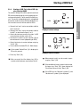
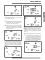
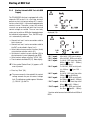
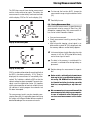
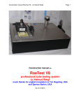
UNITEST
®
Instruction Manual Cat. No. 9061
®
TELARIS Fi/RCD-Analyzer
2
Contents ........................................................................................Page
1.0 Introduction / Scope of Supply ..............................................4
1.1 Model and Type Designation ..................................................4
1.2 Productdescription ................................................................4
2.0 Transport and Storage............................................................5
3.0 Safety Measures ....................................................................5
3.1 Appropriate Usage ................................................................7
4.0 Display / Operation Elements ................................................7
5.0 Carrying out Measurements ..................................................8
5.1 Voltage Measurement ............................................................9
5.2 General Information about RCD Tests ....................................10
5.2.1 Information regarding RCD testing ........................................10
5.2.2 Starting of RCD Test without RCD tripping,
Function Vc/RE ......................................................................11
5.2.3 Starting RCD Test with RCD Tripping, Funtion tRCD/Vc..........12
5.2.4 Starting RCD Test with “RCD Tripping, Function Auto” ..........14
5.2.5 Starting Automatic RCD Test with RCD Tripping ....................16
6.0 Storing Measurement Data ....................................................17
6.1 Infrared Interface, send Measurement Data ..........................18
7.0 Deleting Stored Measurement Data / Display of
All Memory Entries ................................................................18
8.0 Energy Management ..............................................................19
9.0 Maintenance ..........................................................................19
9.1 Cleaning ................................................................................19
10.0 Battery Replacement ............................................................19
11.0 Internal fuse ..........................................................................20
11.1 Indication in the display at defect fuse ..................................20
12.0 Calibration Interval ................................................................20
12.0 Technical Data ......................................................................21
24 month Warranty ..............................................................26
3
English
Contents
Introduction
References marked on instrument or in instruction manual:
Warning of a potential danger, comply with instruction manual.
Reference. Please use utmost attention.
Caution! Dangerous voltage. Danger of electrical shock.
Continuous double or reinforced insulation
complies with Category II.
Warning of potential danger caused by accumulators and batteries.
Conformity symbol, the instrument complies
with the valid directives. It complies with the
EMC Directive (89/336/EEC), Standards EN
50081 and EN 50082-1 are fulfilled. It also
complies with the Low Voltage Directive
(73/23/EEC), Standard EN 61010-1 is fulfilled.
The instruction manual contains information
and references necessary for safe operation
and maintenance of the instrument. Prior to
using the instrument (commissioning / assembly) the user is kindly requested to thoroughly read the instruction manual and comply with it in all sections.
Failure to read the instruction manual or to
comply with the warnings and references contained herein can result in serious bodily injury
or instrument damage.
4
1.0 Introduction / Scope of Supply
You have purchased a high quality measurement instrument of Ch. BEHA GmbH wich will allow you to
carryout measurement over a long time period. The
company Ch. BEHA GmbH is a member of the world
-wide operating BEHA Group with its head office in
Glottertal/Schwarzwald wich also houses our developement centre. The BEHA Group is a leading organisation for Test Measurement Instruments.
1.1 Model and Type Designation
The identification label is located on the rear of the
instrument. It contains the instrument serial number and product designation. When questions arise
regarding the instrument, please always quote
product designation and serial number.
1.2 Productdescription
The UNITEST TELARIS FI/RCD Analyzer allows the
testing of trip times of standard RCDs and selective
RCDs using various residual currents. Additionally,
the ground resistance and contact voltage can be
measured.
• Testing of trip times of standard RCDs and selective RCDs using various residual currents.
• Testing of conventional, selective and all-current sensitive RC protection switches
• Automatic RCD test (all RCD tests are carried
out automatically)
• Nominal residual currents may be selected: 10, 30,
100, 300, 500, and 1000mA
• Automatic phase detection
• Various curve shapes: Sine,1/2 wave rectified DC
current, DC current
• Start of measurement at 0° or 180°
• Display of: trip time, trip current, contact voltage,
ground resistance
• Result assessment, result evaluation
• Data memory for up to 100 measurement resutls
• Infrared interface (RS232) for easy data transfer
• Energy management with integrated auto power
off function
• Large, easily readable display
• Built in compliance with EN 61557 Part 1 and 6,
EN 61010-1, DIN VDE 0413 Part 1 and Part 6,
Transport and Storage / Safety Measures
2.0 Transport and Storage
Please keep the original packaging for later transport, e.g. for calibration. Any transport damage due
to faulty packaging will be excluded from warranty
claims.
In order to avoid instrument damage, we recommend that batteries are removed when not using
the instrument over a certain period of time. However, should the instrument be contaminated by
leaking battery cells, you are kindly requested to return it to the factory for cleaning and inspection.
Instruments must be stored in dry and closed areas.
In the case of an instrument being transported in extreme temperatures, a recovery time of at least 2
hours is required prior to instrument operation.
3.0 Safety Measures
The UNITEST Telaris FI/RCD Analyzer has been designed and checked in accordance with the safety
regulations for Electronic test and Measurement Instruments EN 61010 and IEC 61010, and left our
factory in a safe and perfect condition.
The instruction manual contains information
and references necessary for safe operation
and maintenance of the instrument.
In order to avoid electrical shock, the valid safety and VDE regulations regarding excessive
contact voltages must receive the utmost attention when working with voltages exceeding
120V (60V) DC or 50V (25V)rms AC. The values in brackets are valid for limited ranges (as
for example medicine and agriculture).
Measurements in dangerous proximity of electrical installations are only to be executed when
instructed by a responsible electrical specialist,
and never alone.
If the operator’s safety is no longer guaranteed,
the instrument is to be put out of service and
protected against use. The safety can no longer
be guaranteed if the instrument (or leads):
• shows obvious damage
• does not carry out the desired measurements
• has been stored for too long under unfavourableconditions
• has been subjected to mechanical stress during transport.
Avoid any heating up of the instrument by direct sunlight to ensure perfect functioning and
long instrument life.
Prior to usage, inspect the instrument and test
leads for external damage. Prior to any operation, ensure that connecting leads used and instruments are in perfect condition.
The instrument may only be used within the operating ranges as specified in the technical data
section.
The respective accident prevention regulations
established by the professional association for
electrical systems and equipment must be
strictly met at all times.
5
English
Scope of Supply
1 pc UNITEST TELARIS Fi/RCD-Analyzer
1 pc 3 pole test lead
1 pc Test lead with mains plug
1 pc Croccodile clamps
3 pc Test probe
1 pc Protective Holster
1 pc Carrying Case
6 pcs Battery 1.5V, type IEC LR6 (Size AA)
1 pc Instruction manual
Display / Operation Elements
3.1 Appropriate Usage
The instrument may only be used under those
conditions and for those purposes for which it
was built.
When modifying or changing the instrument, the
operational safety is no longer guaranteed.
The opening of the instrument for fuse replacement, for example, may only be carried
out by professionals. Prior to opening, the instrument has to be switched off and disconnected from any voltages.
Any maintenance and calibration tasks may
only be carried out by our repair service staff.
The instrument may not be operated if the battery case is open.
If the instrument is subjected to an extremely
high electro-magnetic field, its functioning ability may be impaired.
6
4.0 Display / Operation Elements
Display
1. Attention, warning symbol
2. Symbol “Limit” (Limitvalue)
3. Excess (breech) of contact voltage limit
4. Socket error
5. Battery status indication
6. Unit display
7. Display for selective RCD
8. Phase position nominal residual current
9. Contact voltage limit
10. Current type
11. Selected nominal residual current
12. Nominal residual current - multiplication factor
13. Symbol for memory entry
14. Measurement data display
15. Symbol for ramp function
16. Temperature overload, overheating of the instrument
17. AC voltage, display of mains voltage
Operation Elements
18. LCD
19. Key "VC/UL" to select contact voltage limit
20. Nominal residual current selection
21. PE contact electrode
22. Key "Start"
23. Key "Current Type"
24. Key "Phase Position" for nominal residual current
25. Key "Store
26. Key "Send"
27. Key "Clear"
28. Battery case (instrument rear)
29. Infrared RS232 PC interface
30. Key - "Multiplication Factor" for nominal residual current
31. Function selection switch
32. Display key to select individual measurement
results
Carrying Out Measurements
5.0 Carrying out Measurements
1
2
5
4
3
FAT (Final Approval Test) measurements have
to be carried out in compliance with the appropriate applicable standards.
17
6
16
15
7
180¡
I∆N:
2.5x
13
10
11
12
9
English
14
8
18
180¡
I∆N:
2.5x
32
20
Display
VC / UL
tRCD/Vc
Vc/RE
tRCD/Vc
19
20
21
31
22
23
24
30
29
Clear
Send
Store
25
28
27 26
7
Voltage Measurement
5.1 Voltage Measurement
Prior to usage the test instrument and the test
leads have to be tested for correct functioning.
I∆N:
Test leads and test probes may only be touched
at the handles provided. The user must not
touch the test probes.
The measurement connectors may not be connected to external voltages exceeding 300 V AC
or DC to avoid any instrument damage.
Fig. 1
When changing the measurement function or
parameter I∆N and UL parameters, the TELARIS Fi/RCD-Analyzer automatically switches to
the voltage measurement function.
Select measurement function using the function
selection switch (31).
Connect test lead /mains connection lead to the
UUT, as described in figure 1 or 2.
Read measurement data on the display.
No data storing possible !
8
I∆N:
P
Fig. 2
General Information about RCD Tests
5.2 General Information about RCD Tests
The contact voltage UB and the trip time t required
by the RCD to disconnect the subsequent current
circuit from the mains represent important measurement units for the asessment
of an RCD.
The contact voltage represents the voltage present during an insulation error between two simultaneously touchable components.
At a measuring circuit without probe, available
voltages between PE and earth can influence
the measurement.
a) the maximum allowable value for the contact
voltage (25V/50V) may not be exceeded within
any system during tripping at nominal residual
current.
b) the RCD must trip within a time limit of 300ms.
The task of an residual current device (RCD) consists in switching off a system within a defined time
period after an error prior the contact voltage reaches the permissible limit value of 25V / 50V.
The system testing should be started by carrying out
a visual inspection, in particular of the protective
earth connection.
Before using the N-conductor as probe check
that all neutral points have low ohm resistance
to the main neutral line. A available voltage of
the N conductor to the arth can influence the
measurement.
The measuring function uses the N-conductor as a
probe. Check first the connection between the neutral point of the distribution system and earth before the test is started. A possible voltage between
the N-conductor and earth may influence the measurements.
Leakage currents by preconnected loads can
influence the measuring
1. Within the IT system, the protective earth conductor doesnot have to be connected with the
PEN but with the protective earth connection.
2. The protective earth conductor must be connected to the PEN prior to the RCD within the TN system.
3. An insulation measurement as described in Section 5.2 must be performed. In particular it must
be proved, that there is no connection between N
and PE following the RCD.
4. Proof regarding the low impedance connection of
equipotential bonding conductors in compliance
with Section 5.4 must be available.
Attached loads or operating supplies which
contains capacitors or circulating machines
can elongate the trip time.
Time-delayed residual current devices trip at
nominal residual current within 130…500ms,
for double nominal fault current within
60…200 ms. Such RCDs are implemented as
main residual current protection devices
(please refer to IEC 61008-1) and are marked
with the symbol “ S ”.
The protective earth must be free of external
voltage for the RCD test. However if an extraneous voltage is present, the instrument only
indicates the voltage VC having been generated by the measurement. The measurement interruption caused by excess of UL by VC is only
generated by the actual voltage present between the neutral conductor (N) and the protective earth (PE).
Any test and measurement procedures in circuits equipped with residual current devices
should only be performed after having consulted the operator terminals (data processing
systems, material processing, motors, etc.).
Prior to testing, we recommend all loads are
switched off as they could falsify the measurement result.
9
English
For this reason, IEC 60364 prescribes that
Starting of RCD Test
5.2.1 Information regarding RCD testing
The instrument TELARIS RCD Analyzer allows the
measurement of trip times for standard RCDs and
selective RCDs for different residual currents. Additionally, the ground resistance and the contact
voltage can be measured without RCD tripping. The
additional ramp function allows determination of
the exact residual current and trip time. The instrument is equipped with an automatic RCD function
to carry out fully automatic RCD tests.
Table 1 and 2 informs about the type of current to be selected and about multiplication factors of nominal residual current.The multiplication factors may not be selected within all
measurement functions and are in these cases
disabled for the user.
The nominal residual current selection also allows selection of selective RCDs (not possible
for RCD TEST I∆/ta/UB). When selecting the
selective RCD, the symbol "S" (7) appears on
the display.
To carry out a complete socket test, the contact
electrode PE (21) must be touched. If the symbol socket error (4) appears, a PE error is present.
If many measurements are carried out interrupted only by short breaks, the built-in overtemperature protection of the RCD Analyzer
might respond, and the thermometer symbol
(15) appears on the display. Subsequent measurements can only be carried out, once the instrument has cooled down and the thermometer symbol has gone out, thus avoiding any
instrument damage. Any tests at nominal residual currents 10mA / 30mA may be started
even if the thermometer symbol is on, as these
currents do not lead to a heating up of the instrument.
I∆N:
If the RCD trips during testing, the socket error
symbol (4) is displayed. This symbol is also
displayed if the RCD is not in order and an incorrect tripping has been caused!
I∆N:
I∆N:
If the instrument is switched off using function
selection switch or if the instrument automatically switches off due to the automatic power
off function, the pre-set nominal residual current value is maintained. Parameters such as
phase position (0°, 180°), current type (AC, DC
Plus, DC) and the nominal residual current
multiplication factor are reset to the standard
(default) values (0°, AC, x1).
10
The "Attention Symbol" indicates that one measurement unit has exceeded a limit value. When calling
up the measurement data using "Display" key (18),
the "Limit" symbol (2) or "UB>UL" (3) appears for
the respective measurement unit.
Starting of RCD Test
5.2.2
Connect test lead / mains connection cable to
test instrument.
Connect test lead / mains connection cable to
the UUT, as described in figure 1 or 2.
Select desired measurement function Vc/RE
using function selection switch (31).
Set nominal residual current selection (20) to
desired nominal current (depending on RCD).
Select Limitvalue via contact voltage using key
"Vc/UL" (19).
Touch contact electrode PE (21). Note display.
I∆N:
Display at contact voltage
English
Starting of RCD Test without RCD tripping, Function UB/RE
The contact voltage UB and the ground resistance
RE are measured during this test by applying a current amounting to 40 % of the nominal residual current. The contact voltage displayed is extrapolated
to nominal residual current I∆N or to double the nominal residual current I∆N for selective RCDs.
If the symbol "Socket Error" (4) is displayed, a
PE error is present.
Display at earth resistance
Press key "Start" (22).
After successful test the display key (32) is
used to switch between measurement result.
Measurement results can be saved via pressing key “Store” (25).
If the condition of a faulty socket is to be saved,
first press key "Start" (22). Upon hearing the
"Error Signal" press the key "Store" (25).
If the RCD trip, the "Attention" symbol (1) and
"Socket error" symbol (4) are displayed
11
Starting of RCD Test
5.2.3
I∆N:
Display at RCD has tripped
Starting RCD Test with RCD Tripping,
Funtion tRCD/UB
The contact voltage VC is measured during a test,
by applying a current amounting to 40 % of the nominal residual current. The contact voltage displayed is extrapolated to nominal residual current I∆N
or to double the nominal residual current I∆N for
selective RCDs.
Upon the examnation of RCDs a break of 30 sec
is had betweeen pre-test and preliminary test.
A possible reason could be:
• incorrect selection of test current.
• a residual current is present within the net to be
tested, causing the RCD to trip early because it
sums up with the test currents.
• RCD faulty.
The calculated contact voltage is displayed up
to an votage of 70 V
The measurement is interrupted if the contact voltage exceeds the set contact voltage limit. "Attention" (1) and "UB>UL" (3) appears on the display.
I∆N:
I∆N:
12
I∆N:
2 x
Connect test lead / mains connection cable to
test instrument.
Connect test lead / mains connection cable to
the UUT, as described in figure 1 or 2.
Select desired measurement function tRCD/UB
using function selection switch (31).
Set nominal residual current selection (20) to
desired nominal current (depending on RCD).
Set phase position using key 0° / 180° (24).
Set current type (23) and multiplication factor
using key (30).
Starting of RCD Test
The current types and multiplication factors to
be selected at set nominal residual current are
listed in tables 1 and 2.
The measurement is interrupted if the contact
voltage exceeds the set contact voltage limit.
"Attention" (1) and "UB>UL" (3) appears on the
display.
Select contact voltage using key "VC" (19).
Touch contact electrode PE (21). Note display.
If the symbol "Socket Error" (4) is displayed, a
PE error or other socket error is present.
After successful test the display key (32) is
used to switch between measurement result
tRCD and VC within the measurement value
display.
ms
I∆N:
Display at trip time (tRCD)
English
Press key "Start" (22).
I∆N:
Display at limit of contact voltage is exceed
If the RCD does not trip within correct tolerance values (also refer to table 3), the "Attention" symbol
(1) and "Limit" (2) are displayed besides measurement value tRCD.
A possible reason could be:
• incorrect selection of test current.
• a residual current is present within the net to be
tested, causing the RCD to trip early because it
sums up with the test currents.
• RCD faulty.
Display at trip time >300 ms
I∆N:
I∆N:
Display at contact voltage (VC)
Measurement results may be saved pressing
key Store (25).
13
Starting of RCD Test
If the condition of a faulty socket is to be saved,
first press key "Start" (22). Upon hearing the
"Error Signal" press the key "Store" (25).
5.2.4
Starting RCD Test with “RCD Tripping,
Function Auto”
For this test, the trip current I of the RCD is measured. The contact voltage VC is measured during
the preliminary test at a current of 40%I∆N. The
RCD test is resumed after the successful preliminary test at a residual current, rising in steps of 10
% from 40 % I∆N until maximum 140 % I∆N. The
presently active residual current is indicated on the
display and in the event of the RCD tripping the trip
time of the RCD is meausured. The contact voltage
VC is evaluated for the trip current I .
The method of the rising test current is not necessarily binding in compliance with VDE, however represents a useful aid during trouble
shooting.
Test and measurement instruments within networks being protected by RCDs should only be
used after agreement with the final instrument
user (DP systems, process technology, motors, etc.).
Connect test lead / mains connection cable to
test instrument.
Connect test lead / mains connection cable to
the UUT, as described in figure 1 or 2.
Select desired measurement function (I
/tRCD/VC) using function selection switch (31).
Set nominal residual current selection (20) to
desired nominal current (depending on RCD).
No possibility to check selective RCDs.
Set phase position using 0°/180° key (24) and
current type by means of key (23).
Select contact voltage using key "VC/UL" (19).
Touch contact electrode PE (21). Note display.
If the symbol "Socket Error" (4) appears a PE
error is present.
Press key "Start" (22).
After a successful test, it is possible to select
between measurement results trip current I<,
trip time tRCD, and contact voltage VC in the
display (14) using display key (18).
I∆N:
Display trip current
I∆N:
If the contact voltage VC already exceeds the preset contact voltage limit UL during the preliminary
test, the measurement is disabled and the "Attention" symbol (1) and "UB>UL" (3) is displayed.
I∆N:
Display trip time
14
Starting of RCD Test
I∆N:
I∆N:
Display contact voltage
English
The measurement results may be saved by
pressing key Store (25).
If the condition of a faulty socket is to be saved,
first press key "Start" (22). Upon hearing the
"Error Signal", press key "Store" (25).
If due to the ramp current the contact voltage
is exceeded, the measurement is interrupted
and the current is displayed at the level at which
the excess occurred.
To make sure that the RCD is tripping correctly, a
standard test (tRCD/VC) has to be carried out. Example: A correctly functioning RCD has a trip time
of ">300ms" at 50% I∆N, whereas the trip time
smaller than 300ms. When performing standard
test at I∆N.
If the RCD already trips at 50 % I∆N or not at
all at a residual current value higher than 100
% I∆N, the RCD is faulty or the incorrect nominal residual current has been selected. The attention symbol (1) is displayed and the symbol
for exceeding the limit (2) is indicated together with the trip current (tRCD) display
If trip time tRCD of RCD exceeds 300ms, the measurement value for an trip time is displayed as
">300ms". The "Attention" symbol (1) is displayed
and for trip time display, the symbol for overload (2)
appears.
I∆N:
I∆N:
15
Starting of RCD Test
5.2.5
Starting Automatic RCD Test with RCD
Tripping
The TELARIS RCD Analyzer is equipped with a fully
automatic RCD analysis. As a first step, during a
preliminary test, the contact voltage VC is measured at a current of 40 % I∆N and extrapolated to the
nominal current. Thereafter, various AC residual
currents are generated and both trip time and
contact voltage are verified. The user must only
make sure to switch on RCD after tripping between
the individual test programs. Then, the RCD analysis is automatically continued.
I∆N:
.5x
After successful preliminary test the following is
displayed (14):
Connect test lead / mains connection cable to
test instrument.
Connect test lead / mains connection cable to
the EUT, as described in figure 1 or 2.
Select desired measurement function (Auto)
using function selection switch (31).
Set nominal residual current selection (20) to
desired nominal current (depending on RCD).
Select contact voltage using key "VC/UL" (19).
Touch contact electrode PE (21). Note display.
“Pr 1” equals
“Pr 2” equals
“Pr 3” equals
If the symbol "Socket Error" (4) appears a PE
error is present.
“Pr 4” equals
I∆N:
.5x
Press key "Start" (22).
The measurement is interrupted if the contact
voltage exceeds the pre-set contact voltage
limit. The following symbols appear: "Attention
(1), "UB>UL" (3) and "Err
“Pr 5” equals
“Pr 6” equals
“*Pr 7” equals
“*Pr 8” equals
0.5x I∆N 0°, RCD must not trip
0.5x I∆N 180°, RCD must not trip
1x I∆N 0°, RCD must trip within
300ms (S-Type 130 ... 500ms)
(test-time 500ms)
1x I∆N 180°, RCD must trip within 300ms (S-Type 130 ...
500ms)
2x I∆N 0°, RCD must trip within
150ms (S-Type 60 200ms)
2x I∆N 180°, RCD must trip within 150ms (S-Type 60 ... 200ms)
5x I∆N 0°, RCD must trip within
40ms (S-Type 50 ...150ms)
5x I∆N 180°, RCD must trip wit
hin 40ms (S-Type 50 ... 150ms)
*function not to be executed at 500mA and 1000mA
RCDs
16
Storing Measurement Data
The RCD trips several times during measurement
and has to be switched on again. Thereafter, the
measurement is automatically continued and ends
with the display "POS" or "Err" on the display (18).
To interrupt the function AUTO, change the
measurement range using the selection switch
(31)
Possibility to save.
180¡
Display at functioning RCD
Carry out measurement.
Store measurement result by pressing "Store"
key (25).
After successful storeing a short signal is audible and the symbol "M" (13) is displayed, also,
the memory address number briefly appears.
In the event of pressing the Store-key when the
memory is full, the “M” Symbol blinks briefly
and an error signal is heard
I∆N:
2 x
Display at faulty RCD
"POS" is an abbreviation of positive and signifies that
the RCD is functioning correctly. If "Err" (Error) is
displayed, the measurement is immediately interrupted. "Err" indicates a defective RCD or that the
contact voltage has been exceeded. The nominal residual current multiplication factor (12) together
with the phase position of nominal residual current
(9) indicates in which program the automatic test
has been interrupted.
The measurement results may be stored by pressing key Store (25). It is advised to store when using
this range, as the Report Studio Software enables a
detailed decoding of the measurement results.
The data in the memory is maintained if instrument is switched off or during battery replacement.
Double storing of a measurement is impossible !
Under certain, unintentional circumstances
data may be lost or modified during electronic saving. CH. BEHA will not be held liable
for financial and other loss being caused by
data loss, wrong handling or any other reason.
We recommand you to save and transmit the
measurement results daily to your computer.
In case of incidentals outer influences you
can lose saved measurement sof the instrument.
17
English
I∆N:
5x
6.0 Storing Measurement Data
After successful measurement, it is possible to save
measurement value by means of "Store” key (25).
Alltogether, approximately 100 measurement values can be saved. Proceed as follows:
Infrared Interface, send Measurement Data
6.1 Infrared Interface, send Measurement Data
Additionally, all memorised measurement data may
be transferred to the PC (data archive) by means of
an Infrared Interface. For this purpose, the interface adapter and the Software "Report-Studio” (Cat.
No. 1206) and Interface (Cat. No. 1157), available
as an optional feature, are required.
The data transfer procedure is fairly easy:
Apply the Interface adapter to TELARIS
Connect adapter cable to PC (COM 2) via 9pole
D-sub plug (RS232).
Call the "Report-Studio” Software (please refer
to user manual "Report-Studio”).
Select menu item "read data” or select the button "read data from measurement instrument”
by mouse click. The message "send data” appears.
Press key "Send" (26).
Data transfer is carried out. After a few seconds
all stored data is available for further processing in the PC.
For further details, please refer to user manual
"Report-Studio".
7.0 Deleting Stored Measurement Data / Display
of All Memory Entries
It is possible to delete data by using key „Clear" (27).
Furthermore, it is possible to display the total number of measurement value entries on the display:
Display of Total Number of Measurement Value
Entries:
Set measurement range selection switch (31) to
one of the 5 measurements ranges.
Briefly press „Clear” key (27). A short beep signal is audible.
The total number of all measurement values that
have been saved is now displayed.
Delete Last Stored Measurement Value:
Set measurement range selection switch (31) to
one of the 5 measurement ranges.
Briefly press „Clear” key (27). A short beep signal is audible and the number of the memorised
measurement data is displayed.The total number of all stored measurement data is displayed.The display disappears after approximately 2 seconds.
Now release the key „Clear” (27) to avoid deletion of all memory entries.
Deleting the last measurement value can be repeated as often as required, as long as data is
available within the memory.
Deleting all Stored Measurement Values:
Set measurement range selection switch (31) to
one of the 5 measurement ranges.
Press „Clear” key (27) for approx. 5 seconds.
A beep signals are audible. The number of all
stored measurement values is displayed.
The last stored value is deleted after 2 seconds.
After 5 seconds, all values are deleted.
„0“ appears on the display. The memory is completely deleted, the „M" symbol in the display
disappears.
18
Maintenance / Battery Replacement
9.0 Maintenance
When using the instrument in compliance with the instruction manual, no special maintenance is required.
9.1 Cleaning
If the instrument is dirty after daily usage, it is advised
to clean it by using a damp cloth and a mild household
detergent.
Prior to cleaning, ensure that the instrument is
switched off and disconnected from external voltage supply and any other instruments connected
(such as EUT, control instruments, etc.).
10.0 Battery Replacement
If the battery symbol
appears in the display, proceed with battery replacement.
Prior to battery replacement remove the instrument from all measurement circuits.
The right order of the batteries is shown on the
inside of the battery compartment.
Batteries with reversed polarity can lead to instrument destruction. Furthermore, they may
explode or ignite.
Only use batteries as described in the technical
data section type 6LR61.
Switch off the instrument.
Loosen screws on the instrument rear.
Remove battery case cover (by slightly knocking
the instrument in the palm of the hand).
Remove discharged battery.
Insert new battery by respecting the correct polarity.
Replace battery case cover and tighten screws.
Instrument is operational.
Never use acid detergents or dissolvants for cleaning.
19
English
8.0 Energy Management
Approximately 5 minutes after last key operation, the
instrument switches off automatically (auto-poweroff). To switch the instrument on again, turn rotary
switch from the „OFF" position to the desired function.
If the batteries are almost completely discharged, the
battery symbol (5) appears. The instrument continues functioning without necessarily respecting the
specifications.
If the batteries continue to be used and discharged,
the instrument switches off at a point when the minimum battery voltage level is reached and may not be
switched on again.
Battery Replacement / Calibration Interval
Never try to disassemble a battery cell. Never
throw a battery into open flames as this could lead
to an explosion. Never subject batteries to humidity.
Please consider your environment when disposing of used batteries. They belong in a rubbish dump for hazardous waste. Generally
speaking you may return your batteries to the
point of sale.
The appropriate regulations concerning return,
recycling and disposal of used batteries must be
respected at all times.
If the instrument is not used over an extended
time period, we recommend to remove the battery. In the event of instrument contamination
caused by leaking battery cells, the instrument
has to be returned for cleaning and verification
to our factory.
11.0 Internal fuse
The internal fuse protects the instrument from
overload or wrong operation/use. The fuses can
trigger, if tensions > 600 V AC/DC are connected
to the instrument.
The fuse is inside the instrument, the instrument
must be opened for the exchange.
The fuses can only be replaced by returning the
instrument to the factory or to an authorized sales
repair service.
Exclusively use fuse of voltage, current and breaking capacity values in compliance with the
technical data section.
20
11.1 Indication in the display at defect fuse
If the instrument is correctly connected to the
mains and before the measurement displays the
symbols attention (1) and UB > UL (3), the internal fuse has blown.
The fuse must be replaced and the measurement instrument then checked by returning the instrument to
the factory or to an authorized sales repair service.
12.0 Calibration Interval
To obtain the specified measurement result accuracy the instrument should be regularly calibrated by
our after sales service. We recommend a calibration
interval of one year.
Technical Data
13.0 Technical Data
13.1 Tables wih test currents
Table 1 Test Currents Function VC/RE, tRCD/VC, Auto (mA)
I∆N
UB/RE-
x0.5
x1
x2
x5
Measurement:
1000
Prestest
4
12
40
120
200
400
~
5
3,5
15
50
5
10
14
10
20
28
20
50
10,5 15
30
42
30
60
84
60
150 212 150
35
50
70
50
100 141 100
200 283 200
500 707 500
150 105 150
300 424 300
600 849 600
1500
250 175 250
500 707 500
1000
500
1000
2000
English
10
30
100
300
500
Table 2 Ramp Currents Function I<, tRCD/VC (mA)
I∆N
10
4-14
1,4-20
1-14
30
12-42
4,2 - 59
3-42
100
40-140
14-198
10-140
300
120-420
42-594
30-420
500
200-700
71-990
1000
400-1400
Table 3 RCD Trip Times for standard RCB´s
Fi/RCD-Type
Current Type
Test Current
prescribed
I∆N
I∆N
Trip Time
x0.5
0.5x
-
2000ms, I∆N≥100mA: 500ms
IEC61008-1
√
x1
1x
<300ms
500ms
IEC61008-1
√
10mA/
x2
2x
<150ms
150ms
IEC61008-1
√
30mA/
x5
5x
<40ms
40ms
IEC61008-1
√
100mA/
Ramp
0.4x- 1.4x
<300ms
300ms
IEC61008-1
√
300mA/
x0.5
0.35x
-
2000ms, I∆N≥100mA: 500ms
IEC61008-1
√
500mA/
x1
1.4x
<300ms
500ms
IEC61008-1
√
1000mA
x2
2.8x
<150ms
150ms
IEC61008-1
√
x5
7x
<40ms
40ms
IEC61008-1
√
Ramp
0.1x- 1.4x
<300ms
300ms
IEC61008-1
√
x0.5
0.5x
-
2000ms, I∆N≥100mA: 500ms
0664- Part 100
√
x1
1x
<300ms
500ms
0664- Part 100
√
x2
2x
<150ms
150ms
0664- Part 100
√
x5
5x
<40ms
40ms
0664- Part 100
√
Ramp
0.1x- 1.4x
<300ms
300ms
0664- Part 100
√
I∆N
Current Type
Test Time
Standard
Fi/RCD
DIN VDE
Analyzer
21
Technical Data
Table 4 Trip times for selective RCB´s
Fi/RCD-Type
Current Type
Current Type
Test Current
prescribed
I∆N
I∆N
Trip Time
x0.5
0.5x
-
500ms
IEC61008-1
√
x1
1x
130...500ms
500ms
IEC61008-1
√
100mA/
x2
2x
60...200ms
200ms
IEC61008-1
√
300mA/
x5
5x
50...150ms
150ms
IEC61008-1
√
500mA/
x0.5
0.35x
-
500ms
IEC61008-1
√
1000mA
x1
1.4x
130...500ms
500ms
IEC61008-1
√
x2
2.8x
60...200ms
200ms
IEC61008-1
√
x5
7x
50...150ms
150ms
IEC61008-1
√
x0.5
0.5x
-
500ms
0664- Teil100 √
x1
1x
130...500ms
500ms
0664- Teil100 √
x2
2x
60...200ms
200ms
0664- Teil100 √
x5
5x
50...150ms
150ms
0664- Teil100 √
I∆N
Test Time
Standard
Fi/RCD
Analyzer
Table 5 Trip times for RCB´s with over curent protection
Fi/RCD-Type
I∆N
Current Type
Current Type Test Current prescribed Test Time
Standard
Fi/RCD
I∆N
I∆N
Trip Time
x0.5
0.5x
-
2000ms, I∆N≥100mA: 500ms
IEC61009-1
√
x1
1x
<300ms
500ms
IEC61009-1
√
10mA/
x2
2x
<150ms
150ms
IEC61009-1
√
30mA/
x5
5x
<40ms
40ms
IEC61009-1
√
100mA/
Ramp
0.4x- 1.4x
<300ms
200ms
IEC61009-1
√
300mA/
x0.5
0.35x
-
2000ms, I∆N≥100mA: 500ms
IEC61009-1
√
500mA/
x1
1.4x
<300ms
500ms
IEC61009-1
√
1000mA
x2
2.8x
<150ms
150ms
IEC61009-1
√
x5
7x
<40ms
40ms
IEC61009-1
√
Ramp
0.1x- 1.4x
<300ms
200ms
IEC61009-1
x0.5
0.5x
-
2000ms, I∆N≥100mA: 500ms
√
x1
1x
<300ms
500ms
√
x2
2x
<150ms
150ms
√
x5
5x
<40ms
40ms
√
Ramp
0.1x- 1.4x
<300ms
200ms
√
22
Analyzer
√
Technical Data
Table 6 Trip times for selective RCB´s with over curent protection
Current Type
I∆N
Current Type
Test Current
prescribed
I∆N
I∆N
Trip Time
Test Time
Standard
Fi/RCD
Analyzer
x0.5
0.5x
-
500ms
IEC61009-1
√
(RCBO)
x1
1x
130...500ms
500ms
IEC61009-1
√
(100mA/
x2
2x
60...200ms
200ms
IEC61009-1
√
300mA/
x5
5x
50...150ms
150ms
IEC61009-1
√
500mA/
x0.5
0.35x
-
500ms
IEC61009-1
√
1000mA)
x1
1.4x
130...500ms
500ms
IEC61009-1
√
x2
2.8x
60...200ms
200ms
IEC61009-1
√
x5
7x
50...150ms
150ms
IEC61009-1
√
x0.5
0.5x
-
500ms
√
x1
1x
130...500ms
500ms
√
x2
2x
60...200ms
200ms
√
x5
5x
50...150ms
150ms
√
English
Fi/RCD-Type
Table 7 Trip times for impulse resistent RCB´s
Fi/RCD-Type
Current Type
Current Type
Test Current
prescribed
I∆N
I∆N
Trip Time
Test Time
Standard
Fi/RCD
x0.5
0.5x
-
IEC61008-1
√
x1
1x
10...300ms 500ms
IEC61008-1
√
10mA/
x2
2x
10...150ms 150ms
IEC61008-1
√
30mA/
x5
5x
10...40ms
IEC61008-1
√
100mA/
Ramp
0.4x- 1.4x
10...200ms 200ms
IEC61008-1
√
300mA/
x0.5
0.35x
-
IEC61008-1
√
500mA/
x1
1.4x
10...300ms 500ms
IEC61008-1
√
1000mA
x2
2.8x
10...150ms 150ms
IEC61008-1
√
x5
7x
10...40ms
IEC61008-1
√
Ramp
0.1x- 1.4x
10...300ms 200ms
x0.5
0.5x
-
x1
1x
10...300ms 500ms
√
x2
2x
10...150ms 150ms
√
x5
5x
10...40ms
√
Ramp
0.1x- 1.4x
10...300ms 200ms
Analyzer
2000ms, I∆N≥100mA: 500ms
40ms
2000ms, I∆N≥100mA: 500ms
40ms
2000ms, I∆N≥100mA: 500ms
40ms
IEC61008-1
√
√
√
23
Technical Data
Table 8
Fi/RCD-Type
Current Type
Current Type
Test Current
prescribed
I∆N
I∆N
Trip Time
x0.5
0.5x I∆N
-
x1
1x I∆N
<200ms
500ms
VDE 661 √
x5
5x I∆N
<40ms
40ms
VDE 661 √
10mA/
x0.5
0.35x I∆N
-
2000ms
VDE 661 set to 0.5x I∆N¸
30mA
x1
1.4x I∆N
<200ms
500ms
VDE 661 √
x5
7x I∆N
<40ms
40ms
VDE 661 √
x0.5
0.5x I∆N
-
2000ms
set to 0.5x I∆N¸
x1
1x I∆N
<200ms
2000ms
√
x5
5x I∆N
<40ms
40ms
√
Test Time
Standard Fi/RCD
I∆N
Test Time
Standard Fi/RCD
Analyzer
2000ms
VDE 661 set to 0.5x I∆N¸
Table 9
Fi/RCD-Type
Current Type
Current Type
Test Current
prescribed
I∆N
I∆N
Trip Time
fixed
x0.5
0.5x I∆N
-
2000ms
VDE 662 set to 0.5x I∆N¸
(SRCD)
x1
1x I∆N
<200ms
500ms
VDE 662 -
(10mA/
x5
5x I∆N
<40ms
40ms
VDE 662 -
30mA)
x0.5
0.35x I∆N
-
2000ms
VDE 662 set to 0.5x I∆N¸
x1
1.4x I∆N
<200ms
500ms
VDE 662 VDE 662 -
Analyzer
x5
7x I∆N
<40ms
40ms
x0.5
0.5x I∆N
-
2000ms
set to 0.5x I∆N¸
x1
1x I∆N
<200ms
500ms
-
x5
5x I∆N
<40ms
40ms
-
Standardprüfung
General Technical Data
Display ............................................3 1/2 digit LCD
Mains nominal voltage ....................230V/240V +10%-15%
Mains nominal frequency ...............50/60Hz +/- 10%
Reference-Range: ............................+17°C to 27°C, max. 70% rel. humidity
Temperature-Range:........................0°C to 40°C
Relative humidity: ............................max. 80%
Height above MSL:...........................up to 2000m
Battery type .....................................6 mignon 1.5V, Type AA, IEC LR6 (no storage batteries)
Current consumption ......................approx. 15mA
Battery life at average usage ...........approx. 2 years
Auto power off ................................after approx. 5 min.
Built in fuse......................................M 1,0A/250V, 5x20 mm
Data memory ..................................approx. 100 measurements
IR/RS232 interface .........................9600 Baud, 1 start bit, 8 data bits, even parity, 1 stop bit
Degree of contamination .................2
Protection .......................................2, protective insulation, IP50
Overvoltage class ............................CAT II / 300V
Dimensions (LxWxH) ......................235 x 105 x 70mm
Weight ............................................650g (batteries included)
24
Technical Data
Measuring Contact Voltage (UB)
Measurement conditions ................40% I∆N
Measurement time ..........................max 2000 ms,when exceeding limits, immediate cut-off
Measurement range ........................0,6 ... 70,0 V bei I∆N 100, 300, 500, 1000mA
........................................................1...70 V bei I∆N 10, 30mA
Resolution .....................................0,1 V at I∆N 100, 300, 500, 1000mA
Tolerance ........................................-0%...+10% /+6 Digit
Limits .............................................5V / 50V, contact voltage limit UL to be pre-selected
English
Measuring Ground Resistance (RE)
Measurement conditions ...............40% I∆N
Measurement time ..........................max. 2000 ms, when exceeding limits, immediate cut-off
Range: ...............................................1...1999 Ω (at I∆N 100, 300, 500, 1000 mA)
...........................................................0,01...1,99 Ω (at I∆N 10, 30 mA)
Resolution: ........................................1 Ω (at I∆N 100, 300, 500, 1000 mA)
...........................................................0,01 kΩ (at I∆N 10, 30 mA)
Tolerance: .........................................±10%/ ±10 Digit (at I∆N 100, 300, 500, 1000 mA)
...........................................................±10%/ ±20 Digit (at I∆N 10, 30 mA) depends of contact voltage
Measuring Trip Time tA:
Measurement range ........................I∆N 10, 30, 100, 300, 500, 1000mA standard
........................................................100, 300, 500, 1000 mA Selektiv
Test currents ..................................I∆N x0.5 / x1 / x2 / x5 (siee table 1)
Test current type AC, .......................intermittent DC residual current
........................................................DC
Phase position ................................. 0° / 180°
Test current tolerance .....................0...-10%
Measurement time ..........................see table 3, when exceeding limits, immediate cut-off.
Measurement range ........................2...1999ms
Resolution ......................................1ms
Tolerance ........................................± (2%+2Digit)
Limits .............................................25V / 50V, contact voltage limit UL to be pre-selected
Measuring Trip Current (Ramp Funkction)
Measurement ranges ......................10, 30, 100, 300, 500, 1000mA Standard, see table 2
Test currents .................................40% x I∆N...140% x I∆N, bei AC
........................................................10% x I∆N...140% x I∆N, bei pulsierendem Gleichfehlerstrom bzw. DC
Phase position ................................0° / 180°
Measurement time ..........................see table 3, when exceeding limits, immediate cut-off
Display ............................................10% I∆N...140% I∆N
Resolution ......................................10% I∆N
Tolerance ........................................± 10% I∆N
Display ............................................0...1999ms
25
Technical Data / 24 month Warranty
Resolution ......................................1ms
Tolerance ........................................± (2%+2Digit)
Display ............................................0...50 V
Resolution ......................................0,1 V bei I∆N 100, 300, 500, 1000mA
........................................................1V bei I∆N 10, 30mA
Tolerance ........................................-0%...+10% /+6 Digit
Limits .............................................25V / 50V, contact voltage limit UL to be pre-selected
Auto function
Measurement ranges .....................10, 30, 100, 300, 500, 1000mA idem
........................................................100, 300, 500, 1000 mA selective
Test currents ..................................0.5 x I∆N,
........................................................1 x I∆N,
........................................................2 x I∆N,
........................................................5 x I∆N (not at I∆N = 500 / 1000 mA standard or S ),
........................................................automatic selection, also refer to table 1
Phase position ................................0° / 180°, automatic selection
Measurement time ..........................see table 3, when exceeding limits, immediate cut-off
Display ............................................O.K. / bad ( POS / Err )
Limits .............................................25V / 50V, contact voltage limit UL to be pre-selected
Mains Voltage Range
Measurement range ........................3...300V AC
Tolerance ........................................+/-(3%+3 Digit)
Frequency range .............................50/60Hz +/- 10%
Internal resistance ...........................approx. 300kΩ
Overvoltage protection ....................400V AC/DC
24 month Warranty
UNITEST instruments are subject to strict quality control. However, should the instrument function improperly during daily use, your are protected by our 24 months warranty (valid only with invoice).We will
repair free of charge any defects in workmanship or material, provided the instrument is returned unopened and untampered with, i.e. with undamaged warranty label.Any damage due to dropping or incorrect
handling are not covered by the warranty. If the instrument shows failure following expiration of warranty,
our service department can offer you a quick and economical repair.
Subject to technical changes without notice!
26
Qualitätszertifikat • Certificate of Quality
Certificat de Qualité • Certificado de calidad
Die BEHA-Gruppe bestätigt
hiermit, dass das erworbene
Produkt gemäß den festgelegten Beha-Prüfanweisungen
während des Fertigungsprozesses kalibriert wurde. Alle
innerhalb der Beha-Gruppe
durchgeführten, qualitätsrelevanten Tätigkeiten und Prozesse werden permanent durch
e in QualitätsmanagementSystem nach ISO 9000 überwacht.
Die BEHA-Gruppe bestätigt
weiterhin, dass die während der
Kalibrierung verwendeten Prüfeinrichtungen und Instrumente
einer permanenten Prüfmittelüberwachung unterliegen. Die
Prüfmittel und Instrumente
werden in festgelegten Abständen mit Normalen kalibriert,
deren Kalibrierung auf nationale und internationale Standards
rückführbar ist.
The BEHA Group confirms
herein that the unit you have
purchased has been calibrated,
during the manufacturing
process, in compliance with
the test procedures defined by
BEHA. All BEHA procedures
and quality controls are monitored on a permanent basis in
compliance with the ISO 9000
Quality Management Standards.
In addition, the BEHA Group
confirms that all test equipment and instruments used during the calibration process are
subject to constant control. All
test equipment and instruments used are calibrated at
determined intervals, using reference equipment which has
also been calibrated in compliance with (and traceable to)
the calibration standards of
national and international laboratories.
Le groupe BEHA déclare que
l´appareil auquel ce document
fait référence a été calibré au
cours de sa fabrication selon
les procédures de contrôle définies par BEHA. Toutes ces
procédures et contrôles de
qualité sont régis par le systéme de gestion ISO 9000.
Le groupe BEHA déclare par
ailleurs que les équipements de
contrôle et les instruments utilisés au cours du processus de
calibrage sont eux-mêmes
soumis à un contrôle technique
permanent.
Ces mêmes équipements de
contrôle sont calibrés régulièrement à l´aide d´appareils de
référence calibrés selon les directives et normes en vigueur
dans les laboratoires de recherche nationaux et internationaux.
El grupo BEHA declara que el
producto adquirido ha sido calibrado durante la producción
de acuerdo a las instrucciones
de test BEHA. Todos los procesos y actividades llevados a cabo dentro del grupo BEHA en
relación con la calidad del producto son supervisados permanentemente por el sistema
ISO 9000 de control de calidad.
Adicionalmente, el grupo BEHA
constata que los equipos e instrumentos de prueba utilizados
para la calibración también son
sometidos a un permanente
control. Estos equipos e instrumentos de prueba son a su vez
calibrados en intervalos regulares valiéndose de equipos de
referencia calibrados de acuerdo a directivas de laboratorios
nacionales e internacionales.
®
CH. BEHA GmbH
Elektrotechnik - Elektronik
In den Engematten 14
D-79286 Glottertal / Germany
Tel. +49 (0) 76 84 / 80 09 - 0
Fax +49 (0) 76 84 / 80 09 - 410
e-mail: [email protected]
internet: http://www.beha.com
Quality Management System
ISO 9001
Connemara Electronics Beha GmbH
Industrial Park
Carrigaline, Co. Cork
Republic of Ireland
Tel. (+353) 21 4919000
Fax (+353) 21 4910010
e-mail: [email protected]
IQ N ET
I.S./ISO 9002/EN 29002
Quality Management System
AENOR Spain AFAQ France AIB-Vincotte Inter Belgium APCER Portugal BSI United Kingdom CSIQ Italy
CQS Czech Republic DQS Germany DS Denmark ELOT Greece FCAV Brazil IRAM Argentina JQA Japan
KEMA Netherlands KSA-QA Korea MSZT Hungary NCS Norway NSAI Ireland ÖQS Austria PCBC Poland PSB Singapore
QAS Australia QMI Canada SFS Finland SII Israel JQA Japan SIQ Slovenia SIS-SAQ Sweden SQS Switzerland
IQNet is represented in the USA by the following IQNet members: AFAQ, AIB-Vinçotte Inter, BSI, DQS, KEMA, NSAI and QMI
27
®
Re g . No . 3 3 3 5
11/2002
28
CH. BEHA GmbH
Elektronik - Elektrotechnik
In den Engematten 14
79286 Glottertal / Germany
Tel.: +49 (0) 76 84 / 80 09 - 0
Fax: +49 (0) 76 84 / 80 09 - 410
Techn. Hotline: +49 (0) 76 84 / 80 09 - 429
internet: http://www.beha.com
e-mail: [email protected]
PTEB9061-00-RS