1
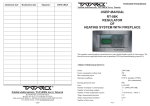
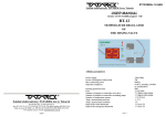
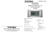
R08TH/2010/v.1.0 ANG Zakład elektroniczny TATAREK Jerzy Tatarek USER MANUAL RT-08TH REGULATOR OF HEATING CIRCULATION WITH THE SOLAR COLLECTOR v.1.0 (04.11.2009 program from 1v0) The regulator controls the heating system in which a heat source is a solar collector. The heat receiver is a buffer. The pump of the solar collector runs with a continuous control of its rotation, which enables a optimal use of the collector heat. The regulator is equipped with a clock which at selected times of the day turns on the circulating pump of the applicable water and the alternative heat source as well (electric heater, gas boiler and the like). 1.Basic parameters Power supply Power consumption without the load Max. connection power Operation conditions 230V/50Hz 5W 750W 0-50 oC, humidity10-90% no condensation IP41 6,3A/250V Housing protection class Fuse Number of outputs to control the pump of the solar collector Zakład elektroniczny TATAREK Jerzy Tatarek 50-559 Wroclaw, 75 Swieradowska st. ph. (071) 367-21-67, 373-14-88, fax 373-14-58; Tax index number 899-020-21-48; Bank account: BZ WBK S.A. WROCLAW 6910901522-0000-0000-5201-9335 www.tatarek.com.pl.; E-mail: [email protected] 12 Number of additional outputs Number of temperature sensors of the solar collector Number of water temperature sensors Temp. measurement precision Temp. measurement resolution Number of the time zones 1 1 *1A/ 230V/50Hz (triac, continuous rotation control) 2 * 250W/230V/50Hz 1 * KTY84 (-30...+200 oC) 2 * KTY81 (-10...+100 oC ) 2 oC 0,5 oC 3 2. Operation principle The RT-08TH SOLAR regulator is a microprocessor regulator that controls the operation of the heating system consisted of the buffer BUF and the solar collector KSL (see fig.1). The pump of the collector P2 turns on with maximum rotation if the temperature of the collector (T1) is higher than the temperature of the buffer (T2) by the value of the “DeltaKSL” parameter. If the difference begins decreasing then the rotation of the pump accordingly get lower down to complete switch-off when the difference reaches the “MinKSL” parameter value. Thanks to the installed clock you can set during the day the times of heat comfort. In those times the circulating pump of the warm applicable water CWU (P1) turns on cyclically in order to ensure a fast reaction of the CWU, and the electric heater (or another heat source) gets started when the temperature measured in the upper part of the buffer is lower than the “TminBUF” parameter. Admission date Realization date Signature The regulator realizes additional functions of the control: - protection of the buffer against overheating - protection of the solar collector KSL against overheating - protection of the KSL against freezing - signalling of any damages to the temperature sensors - URLOP operation mode with the cooling of the system Fig.1 Operation layout of the regulator 2 11 Remarks CE CONFORMITY DECLARATION Ref. No. 58.RT.01.2007/1/B We, ZAKŁAD ELEKTRONICZNY TATAREK Jerzy Tatarek 75 Swieradowska St. , 50-559 Wroclaw declare under our sole responsibility that the product: Regulator of heating circulation with the solar collector is in conformity with the basic requirements included in Directive EMC 2004/108/WE of 15.12.2004 (the electromagnetic compatibility law of 13.04.07) and Directive LVD 2006/95/WE of 21.08.07 (Laws Journal of 2007 No. 155 pos. 1098) regarding the requirements for electric devices. To the conformity evaluation the following harmonized standards were used: PN-EN 60730-1: 2002 - Automatic electric regulators for house usage and the like. Part 2-1: Specific requirements regarding electric regulators for electric house devices Automatic electric regulators for house usage and the like. Part 1: General requirements. PN-EN 55022: 2000 Electromagnetic compatibility (EMC)- IT devices Characteristics of radioelectric noises. Acceptable levels and measurement methods Complementary information: Laboratory IASE 51-618 Wroclaw, 1 Wystawowa st. Test report No. Solar collector Buffer T1 T2 T3 temperature sensor of the solar collector temperature sensor of the solar collector mounted in the lower part temperature sensor of the solar collector mounted in the upper part P1 P2 G3 circulating pump of the warm applicable water feeding pump of the buffer from the solar collector (continuous control of the rotation) electric heater or another heat source 1.1 Operation of the circulating pump (P1) model: RT-08, RT-08T, RT-08K, RT-08P, RT-08TH, RT-08TL PN-EN 60730-2-1: 2002 - KSL BUF During the heat comfort time the circulating pump (P1) turns on for a time defined by the “tZałPC” parameter and turns off acc.to the “tWyłPC” parameter. Normally every 15 minutes the pump turns on for a 2min time. Outside of the heat comfort time zone the pump doesn’t run. 1.2 Operation of the KSL pump (P2) The collector pump P2 turns on with maximum rotation if the collector temperature (T1) is higher than the buffer temperature (T2) by the value of 10 oC (”DeltaKSL” parameter, see PARAMETERS). If the temperature difference begins decreasing then the rotation of the pump accordingly get lower down to complete switch-off when the difference reaches 2oC (”MinDelta” parameter). If the buffer temperature BUF exceeds 60 oC (”TmaxBUF” parameter) the CWU pump turns off. ! Despite limiting the temperature of the CWU container (”T.max CWU” parameter) on the output of the warm water you need to apply a thermostatic antiburn valve which through mixing with cold water keeps the temperature range of 35 oC-60 oC.(set by the setting handle). ! Exceeding the maximum temperature of the solar collector (”T.maxKSL” parameter) causes turning on the KSL pump (P2), protecting the collector against overheating. The KSL protection has a higher priority than limiting the temperature of the CWU. ! Exceeding the minimum temperature of the solar collector (”T.minKSL” parameter) causes turning on the KSL pump (P2), protecting the collector against freezing. The KSL protection has a higher priority than limiting the temperature of the CWU. 39/DL/I/07 of 22.06.2007 41/DL/I/07 of 03.07.2007 Electronic Engineering Plant TATAREK has initiated management system and complies with the following standard : ISO9001: 2000 CERTIFICATE No. 133/2004 of 01.2004 Polish Foreign Trade Chamber The last two digits of the year in which the CE marking was affixed: 07 1.3 Operation of the heater (G3) (or another heat source) When the heat comfort setting is active the electric heater or another heat source ) warms up the upper part of the container.The heater turns off when the temperature measured in the upper part of the buffer container reaches the “TminBUF” value (default setting 40 oC ) and again turns on when the temperature falls by 4 oC . Outside of the heat comfort zone the heater doesn’t work. ! Swithing on the heater can be prevented by setting the “TminBUF” parameter at minimum of 20 C o Place of issue: Manufacturer representative: (The text “off” shows up) Wroclaw Mirosław Zasępa Date of issue: Position: 08.2007 Konstruktor ! Power of the heater connected directly to the regulator cannot exceed 500W. For more powerful heaters you need to apply an auxiliary contactor. ! With turning on the heater G3 simultaneously the nonvoltage contacts of the relay STEROWANIE get switched over. You can use them to connect another alternative heat source (e.g. gas boiler) 10 3 WARRANTY 1.4 URLOP mode This is a special operation mode applied when for a longer timer the system is not normally used, that is, there’s no heat receiving from the buffer. In this mode the maximum temperature of BUF is set at 45 oC leaving a reserve for accumulating the heat in case of protecting the collector against overheating. The heat is dispersed in the collector when its temperature falls below the buffer temperature by the “DeltaKSL” value (Cooling the system by night and on overcast days). ! In the URLOP mode the KSL protection against overheating should not be switched off. ! In the URLOP mode turning on the heater G3 is blocked. 2.Handling the regulator On the control panel (Fig.2) are the controls of the regulator. The regulator state is shown on the text display (1). The displayed screens inform about device operation, sensor temperature, enable changing the parameters etc. The change of the screen is made by pressing the WYBIERZ button (2). If this is a screen that enables changing a parameter then you need to press the USTAW button (5). The parameter field starts blinking the value of which can be altered with the "+" (2) or "-" (4) button. 1.Warranty is valid [24] months from the date of sale. 2.Producer does not take responsibility for any mechanical damages made by user. 3.MAKING REPAIRS OR MODYFYING THE DEVICE BY USER IS FORBIDDEN AND CAUSES WARRANTY CANCELATION 4.Warranty card is valid only with date of sale, seller's signature and stamp 5.Warranty and after-warranty repairs should be done only by producer, damaged regulators should be sent to producer in order to make all repairs needed. 6.Warranty protection involves the EU 7.Warranty does not exclude, not restrict and not suspend buyer’s rights coming from the incompatibility of the article with the agreement (Laws Journal No. 141 Pos. 1176) WARNING ! ANY MODIFICATION OF THE REGULATOR MADE BY USER CAN BE THE CAUSE OF SAFETY CONDITIONS DETERIORATION AND CAN EXPOSE THE USER TO ELECTRIC SHOCK OR DAMAGE DEVICES SUPPLIED. Connection cable of regulator may be replaced only by producer or his authorized service locations WARNING! 1. Producer does not take the responsibility for damage caused by atmospheric discharge 2. and overvoltage in the mains 3. Burnt fuses are not subject to warranty replacement Date of sale Seller's signature and stamp Fig.2 Control panel ARGO-FILM Recycling Plant No. 6 180 Krakowska st., 52-015 Wroclaw Worn out electronic and electric devices must be transfered to ph.: 071 794 43 01, 0 515 122 142 the utilization collection place, where will be accepted for free Register No.. GIOS: E 0002240WZ 1. Text display 2. Increase button 3. Parameter button 4. Decrease button 5. Confirmation button With the USTAW button (5) you confirm the changes - the parameter field stops blinking. The changed parameter not confirmed for 10s is not stored by the regulator. The field stops blinking and the previous value is restored. Zakład elektroniczny TATAREK Jerzy Tatarek 50-559 Wroclaw, 75 Swieradowska st ph. (071) 367-21-67, 373-14-88, fax 373-14-58; tax index number 899-020-21-48; Bank account : BZ WBK S.A. O/WROCŁAW 6910901522-0000-0000-5201-9335 www.tatarek.com.pl.; E-mail: [email protected] 4 9 Model change of the “TmaxKSL” parameter defining the protection temperature of the solar collector (Parameter of the level 3). You press: repeatedly “WYBIERZ” till the “PoziomUS 0”screen of setting the parameters shows up. “USTAW” -> “0” begins blinking threefold “+”->”3” blinks „USTAW” -> “3” stops blinking (the parameter of the level 3 is chosen) „WYBIERZ”->”TmaxKSL” shows up „USTAW” -> the actual value to be changed starts blinking “+/-”-> you set a new value „USTAW” -> you confirm the new value repeatedly “WYBIERZ” till the “***” screen of setting the parameters shows up. 3. Installing the regulator ! ! ! ! THE REGULATOR IS SUPPLIED BY 230V/50HZ . ANY MOVES REGARDING INSTALLATION SHOULD BE MADE ATTHE DISCONNECTED MAINS. THE REGULATOR HAS TO BE CONNECTED TO THE MAINS WITH THE ZERO-PIN THROUGH A DIFFERENTIAL DEVICE ACC. TO THE VALID LAWS THE REGULATOR SHOULD NOT BE EXPOSED TO WATER AFFECTING. ITS ENVIRONS OUGHT TO BE CLEAN. THE PRODUCER DOESN'T TAKE ANY RESPONSIBILITY FOR DAMAGES CAUSED BY WRONG USAGE OF THE REGULATOR. Connection diagram of the elements of the regulator is presented on fig. 3 Temperature sensors STEROWANIE /CONTROL Pump P1(PC) 230V/50Hz Pump P2 (KSL) 230V/50Hz Heater G3 230V/50Hz MAINS 230V/50Hz Fig.3 Electric wiring layout T1 T2 T3 temperature sensor of the solar collector KSL (type KTY84) temperature sensor of the BUF buffer mounted in the lower part (type KTY81) temperature sensor of the BUF buffer mounted in the upper part (type KTY81) 2.1 Time zones The regulator is equipped with the clock, which enables an automatic change of the operation mode at different times of the day. The 24-hr is devided into 3 zones ($1, $2, $3) and the time span when no zone is active that is STREFA 0 or BAZA. The time zone is defined by the start time (OD) and the end time (DO). In the regulator the following zone default program is set: STREFA 1($1) STREFA 2 ($2) STREFA 3($3) OD 6.00 DO 8.00 OD 14.00 DO 17.30 OD 20.00 DO 22.30 ! the zones $1, $2 or $3 are the heat comfort zones. When they’re active, the circulating pump can operate and the warming-up of the buffer is possible. 2.2 Screens The emergency screen is not visible till one of the following emergency situations takes place: 1. Damage of the sensor T1 of the solar collector. The text "T1(KSL)" shows up. 2. Damage of the sensor T2 of the buffer / „T2(BUF)“ 3. Damage of the sensor T3 of the buffer / „T3(BUF)“ 4. Exceeding the limit temperature of 90o C in the buffer / “TmaxBUF” ALARM !! Tmax BUF ALARM !! T1(KSL) The emergency situation is accompanied by a broken sound signal which can be cancelled with the USTAW button. Operation screen of the collector On the display are shown the symbols of devices. KSL- solar collector, BUF - buffer. Below them respectively the measured temperature. If instead of the degree symbol (o) the “!” symbol is shown then that means exceeding the preset temperature and turning on the protection mode (see the description of the parameters). The blinking arrow indicates the actual heat flow in reaction to the pump operation. KSLBUF 90o 45o If the URLOP mode is turned on ( with cooling the system) the URLOP text blinks and the arrow indicating the heat flow can be directed opposite (that is from the buffer to the collector) if the pump runs in the cooling mode. This is a stable screen. In order to change it you need to press the WYBIERZ button. ! Sensor T1 you need to connect so that the red cable is connected to the “+” contact ! When there’s no T3 sensor the heater is blocked. ! Power of the heater connected directly to the regulator must not exceed 500W. For more powerful heaters you need to apply an additional contactor. ! With turning on the heater G3 simultaneously the nonvoltage contacts of the relay STEROWANIE get switched over. You can use them to connect another alternative heat source (e.g. gas boiler) Operation and circulation screen of the heater On the display are shown the devices symbols : “Grz”- heater, “BUF” - buffer and “PC” - circulating pump. Below the symbol of the buffer the temperature in the upper part of the container (T3) is shown. If the sensor T3 is not mounted then in place of the temperature value the “---” text shows up and turning on the heater will be blocked. Th blinking arrow indicates the actual heat flow in reaction to the heater operation. 8 5 PARAMETER LEVEL 11 Grz BUF TITLE DeltaKSL MinDelta If the circulating pump runs then at its symbol (PC) the “*” symbol blinks. This is a stable screen. In order to change it you need to press the WYBIERZ button. Screen of the regulator operation t.ZalPC RANGE o 10 C o o 1...20 C 0...20 C No more than DeltaKSL 0,5...30,5 FUNCTION DEFAULT o Temperature difference between the solar collector and the buffer causing the operation of the KSL pump P2 with max rotation. Temperature difference between the solar collector and the buffer causing the switch-off of the KSL pump P2 2 C 2 min Operation time of the circulating pump 15 min Break time of the circulating pump min t.WylPC 0,5...30,5 min TrybKSL AUTO the regulator can operate in the mode: AUTO KSL pump runs in the function of the temperatures difference between KSL and CWU URLOP KSL pump runs in the cooling mode of the system. This mode should be activated if for a longer time there’ll be no heat receiving from the buffer. MAN KSL pump turns on with maximum efficiency no matter what the KSL and BUF temperature are (e.g. for venting the system, snowing off the collector). The switch-on lasts for the time determined by the "CzasMan" parameter (see PARAMETER LEVEL 1). After the time the AUTO mode is restored. It's a unstable screen, that is after 10s from the last pressing of any button the screen switches to that of the whole system operation. All the next screens are unstable. PARAMETER LEVEL 2 TITLE RANGE DEFAULT STRF1 od STRF1 do STRF2 od STRF2 do STRF3 od STRF3 do 0:00...23:45 0:00...23:45 0:00...23:45 0:00...23:45 0:00...23:45 0:00...23:45 6:00 8:00 14:00 17:30 20:00 22:30 TITLE RANGE Normally the level of setting is 0, which means the parameters are not available. After switching to the level 1,2 or 3 the subsequent screens show the parameters. The last screen displays "****" after which the comeback to the previously described screens follows. 6 FUNCTION DEFAULT o T.maxKSL 80..200 oC 110 C KSL protection against overheating. Maximum temperature of the collector after exceeding it the KSL pump P2 turns on, protecting o the collector against overheating. The setting of 200 C (”off” text) indicates turning off this function. T.minKSL -30..+10 o C +3 oC KSL protection against freezing. Minimum temperature of the collector after exceeding it the KSL pump P2 turns on, protecting o the collector against freezing. The setting of -30 C (”off” text) indicates turning off this function. This function can be turned off in case of using a nonfreezing fluid in the solar T.maxBUF 40..85 oC 60 oC T.minBUF 20..60 oC 40 oC ObrotMIN 10...100% 30% t.minKSL 10…900s 10s CzasMAN 1...30min 5min BUF protection against overheating. Maximum temperature of the buffer after exceeding it the pump turns off, protecting the buffer against overheating. KSL protection has a higher priority than BUF one.. Temperature of the upper part of the buffer after reaching it the heater or another alternative heat source turns off The setting of 20 oC (”off” text shows up) indicates turning off the warming-up option. . Minimum rotation of the pump ensuring a stable operation. The setting of 100% enforces ON/OFF operation. Minimum operation/break time of the collector pump. It protects against too often turning on/off the pump Operation time of the KSL pump P2 in the MAN mode ZEGAR $1 17:15 PoziomUS 0 Start time of the 1st time zone End time of the 1st time zone Start time of the 2nd time zone End time of the 2nd time zone Start time of the 3rd time zone End time of the 3rd time zone PARAMETER LEVEL 3 Screen of the clock The screen shows the current time and number of active time zone. The time correction is possible after pressing the USTAW button (5). In reaction to that the minutes field starts blinking. The blinking value you can change by pressing the “+” (2) or “-” (4) button. By pressing the WYBIERZ button (3) you step through to the hours field the value of which you can also change by the “+” (2) or “-” (4) button. Pressing the USTAW button (5) confirms the changes ( the clock field stops blinking). Screen of setting the parameters FUNCTION 7