1
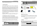
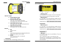
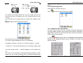
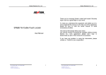
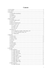
ST330 xDSL Tester
ST330 xDSL Tester
Introduction
Thank you very much for purchasing our product.
ST330 xDSL Tester
User Manual V1.6
This User’s Manual contains useful information about the functions,
installation and wiring procedures, operation procedures, and the
troubleshooting of the ST330. To ensure correct use, please read this
manual thoroughly before operation. Keep this manual in a safe place for
quick reference in the event a question arises.
Revisions
Edition: March 2007
Structure of the Manual
This User’s Manual consists of the following 8 chapters.
Chapter
Title
Description
1. Summarization
General introduction about ST330
2. Checking the Contents of
the Package
Introduce the contents of the package.
3 . Safety
Describes the precautions to be taken
in order to use the ST330 safely.
4. Notice in operation and using Introduce some notice in operation and
using.
5. System configuration
and quick reference
6. Function and Specification
Give the specifications and
functions of the instrument.
7. Operation
Give the instructions to useST330.
8.
1
Gives a diagram and structure
introduction of the ST330.
Analyzing and
Solution for faults
Describes how to solve small
fault of ST330 by yourself.
2
ST330 xDSL Tester
Contents
Chapter 1 Summarization……………………………….………..…….......5
Chapter 2 Checking the contents of the package ………………………..6
Chapter 3 Safety…………………………………………………..………..6
Chapter 4 Notice in operation and using……………………….….….….7
4.1 General operation precautions…………..................7
4.2 Suggestion for using……………………..…...………...8
Chapter 5 System configuration and quick reference…………………...9
5.1 System configuration…………………………...……….9
5.2 Quick reference ………………………………………..10
5.2.1Front panel………………………………...…………..10
5.2.2 Up side…………………………………………...……11
5.2.3 Down side……………………………………………..12
5.2.4 Other parts……………………………….……………12
Chapter 6 Function and specification…………………………………...14
6.1 xDSL test…………………….……………………….….14
6.2 LAN test………………………………………………....14
6.3 DMM test………………………………………………..14
6.4 MODEM emulation…………………………………….14
6.5 File management………………………………………15
6.6 Help………………………………………………………15
6.7 Other specification…………………………………….15
Chapter 7 Operation……………………………………….……….…….…16
7.1 Switch on/off, restart………………….………………...16
7.2 Operation interface description……………….……...16
7.2.1 State bar………………………………………..……..17
7.2.2 Function bar………………………………….…..…...17
7.2.3 Tools bar……………………………………………. 17
7.3 xDSL test…………………………………………..…....18
7.3.1 Physical layer test…………………………….……..20
7.3.1.1Physical layer parameters…..……………….……..21
7.3.1.2 G.SHDSL modular……... ………..………….……..24
3
ST330 xDSL Tester
7.3.1.3 Noise Curve………..………………….……..26
7.3.2 Modem parameter set…………………………...…..27
7.3.2.1 ADSL2/ADSL2+ modular…….……………...…..27
7.3.2.2 G.SHDSL modular…….….……….…………...…..29
7.3.3 PPPoE properties………………………………...….30
7.3.4 PPPoE dial……………………………………….…...31
7.3.5 Network layer tester……………………………..……32
7.3.6 Webpage browse………………………………...….35
7.3.7 Loopback Test…………………………………….….36
7.3.8 FTP client……………………………………………..36
7.3.9 Webpage speed test………………… ……… ……37
7.4 LAN test…………………………………….……….....38
7.4.1 Network card properties………………….……...…39
7.4.2 PPPoE properties……………………..…….………..40
7.4.3 PPPoE dial……………………………….…..……...41
7.4.4 Network layer test……………………………….…..42
7.4.5 Fixative IP test…………………….……………….….44
7.4.6 Webpage browse………………….…………….….45
7.4.7 FTP client…………………………………………..…46
7.4.8 Webpage Speed test…………..........…………….....47
7.5 DMM test………………………………………………48
7.6 Modem emulation…….….….….….….….….…..…..51
7.7 File management………………………………….…..52
7.7.1 Record browse………………………...……………..52
7.7.2 Memory key save……………………………………..54
7.7.3 File transfer……………………………………..….….55
7.7.4 File Management…………………………………....56
7.8 Help……………………………………………...……..57
7.8.1 System upgrade……………………………………...58
7.8.2 Use notes……………………………………………..59
7.8.3 Function Set…..………………………………….….59
7.8.4 Recalibrate……………………………………………60
7.8.5 About……………………………………………….…60
7.9 Charge………………………………..………………….61
4
ST330 xDSL Tester
7.10 Battery replacement………………………………..…61
Chapter 8 Analyzing and Solution for faults…………………………...….64
ST330 xDSL Tester
Mark
Specifications
ADSL
ADSL Modem
ADSL2+
ADSL2+ Modem(ADSL/ADSL2/READSL)
Standard accessories
1. Summarization
ST330 is designed for present all kinds of xDSL line including ADSL,
ADSL2, ADSL2+, READSL. It not only can test xDSL physical layer
parameter and also can help you to confirm whether your line is proper
to provide xDSL service. It also can evaluate your line quality. It also can
have PPPoE dial, do IE network page browsing, and emulate user’s PC+
Modem by inside Modem of ST330 to test the connection between user
and ISP provider. You can have all kinds of test such as Ping, Ipconfig,
Rouge, Tracert after successful dial. ST330 also can emulate the user’s
PC to test broadband IP line or have PPPoE dial by user’s Modem to test
the connection of IP network and Modem problem or to remove the
problem arisen by computer.
ST330 takes 240X320 TFT true color LCD, touching screen and
embedded system. So it is easy to operate and to see the test result.
2. Checking the contents of the package
Unpack the box and check the contents before operating the instruments.
If some of the contents are not correct or missing or if there is physical
damage, contact our company and the dealer from which you purchased
them. If you are adding or replacing the standard or optional accessories
indicated below, make sure to purchase them from us or your dealer.
Check that the model name and suffix code given on the name plate on
the back of tester.
Model
Suffix Code
Specifications
-CN
Chinese
-EN
English
ST330
5
The following standard accessories are supplied with the instrument.
Check whether all the contents are attached and undamaged.
Charger
Direct Ethernet
Test cord
LCD protective board
Touching
Network line
User manual
stick
List
Carry case
Handle
Optional accessories
The following optional accessories are available for purchase separately.
When you receive the order, Check whether all the contents are attached
and undamaged.
Keyboard which can be linked to tester USB port
Mouse which can be linked to tester USB port
Memory key
3. Safety
Make sure to comply with the following safety precautions.
Not complying might result in injury or death.
WARNING
6
ST330 xDSL Tester
ST330 xDSL Tester
Don’t input things with electricity to USB port and please don’t short it
by metal things.
Power Supply
Ensure that the source voltage matches the voltage of the power
supply or else maybe there will be some damage to the Tester.
Battery changing
Please refer to the 7.10 item.
Display screen
Protective board and film are affixed to the LCD at the time of
shipment. Please remove it before use.
Do Not Operate in Explosive Atmosphere
Do not operate the instrument in the presence of flammable liquids
or vapors. Operation of any electrical instrument in such an
environment constitutes a safely hazard.
Cleaning
The instrument uses many plastic parts. When cleaning, wipe using
a dry soft cloth. Do not use volatile chemicals since this might cause
discoloring and deformation.
Back cover
Do not separate the top and bottom cover unless you are replacing the
battery or Modem. Battery replacement should only be carried out by
a person who received proper training. Some areas inside the
instrument have high voltage that is dangerous if they are not
handled properly.
Protecting the case and operating panel
Do not pour volatile agents on the case or operation panel, this can l
ead to malfunctioning.
LCD
If, by accident, the surface of the LCD is damaged and the liquid, or
let it touch the skin. If the liquid happens to come in contact with the
eye or the mouth, immediately rinse with water. If it comes in contact
with the skin or clothes, wipe it with alcohol and then wash it with
soap and water. Otherwise, damage to the skin or clothes may result.
In addition, be careful not to cut the skin (fingers, hands, etc) with the
broken glass. Touching the edges of the broken glass can cause
injury.
When the instrument is not used for a long period of
time
When the instrument is not used for a long period of time, the
battery characteristics may have deteriorated. The battery also may
take longer to charge. If the operation period of fully charged battery
is excessively short, the battery must be replaced. To replace the
battery, see the “Battery Replacement Manual”.
When moving the instrument
Check that the power cord and connection cables are removed.
After use, unplug the power cord from the socket.
Malfunction
Never continue to use the instrument if there are any symptoms of
trouble such as strange sounds, odors, or smoke coming from the
instrument. In such cases, immediately turn OFF the power and
unplug the power cord. If the instrument has malfunctioned, contact
your dealer.
4. Notice in operation and using
4.1 General operation precautions
Test Interface
Please firstly connect the test cord to ST330 test interface and then
connect to the test line. Please don’t touch the metal pars of clamps
to avoid the high dangerous voltage.
USB port
7
4.2 Suggestion for using
Please charge the battery full before your first using and usually
using. Please refer to 7.9 item about charging.
When you operate function keys, please use touching stick and
please click LCD proper.
8
ST330 xDSL Tester
If there is any abnormal phenomenon, please press RESET key to
reset or press OFF key to switch on again.
Please don’t put the instrument under the strong direct sunlight and
near the origin of heat. Or else, there will be bad affect to circuit.
Condensation may occur if the instrument is moved to another place
where the ambient temperature is higher, or if the temperature if the
room changes rapidly. In this case, let the instrument adjust to the
new environment for at least one hour before using the instrument.
Using the instrument near strong magnetic field sources will have
adverse affects on the internal circuit of the instrument.
If you are using a portable phone to transmit measured data, move
the portable phone at least 1 m away from the instrument and
Measuring Cables. The measured data can receive undesirable
effects from the electromagnetic wave generated by the portable
phone.
ST330 xDSL Tester
5. System configuration and quick reference
5.1 System configuration
:
LAN Port:Ethernet port.
xDSL Modem:Different Modem can perform different function.
xDSL Port For user xDSL line link and DMM test link.
Mainly include ADSL,
ADSL2, ADSL2+, READSL, VDSL, etc.
USB HOST
: Link
USB equipment, keyboard, mouse and
memory key.
5.2 Quick reference
5.2.1ST330 Front Panel
9
10
ST330 xDSL Tester
ST330 xDSL Tester
5.2.2 ST330 Up side
Indicator Lights
Power Indicator Light
Red color, power supplied
Ethernet Indicator Light:
Green color, normal Ethernet connection
Shining green color, Ethernet data transmission
xDSL LINK Indicator Light
Shining green color, xDSL Modem being connected
Green color, xDSL connected.
xDSL ACT Indicator Light
Shining green color, xDSL data transmission.
ON
Switch on tester.
OFF
Switch off tester when there are abnormal phenomena,
such as tester dead or slow run speed.
Buttons
Touching stick
Use it to point icons from display screen to have operation.
Insert it into left up corner of tester when it is not used.
Ethernet port 1
It is RJ45 port. It is for linking Ethernet network cord or
Broadband IP with RJ45 network line plugs. It is for cross
(
used meantime)
:
network cord link. NOTE Ethernet port 1 and 2 cannot be
Ethernet port 2
It is RJ45 port. It is for linking Ethernet network cord or
Broadband IP with RJ45 network line plugs. It is for direct
(
used meantime)
:
network cord link. NOTE Ethernet port 1 and 2 cannot be
RESET
Reset system when there is an abnormal
phenomenon occurs.
LCD Display
TFT true color screen, 240×320 lattice, touching screen.
11
xDSL port
It is the port for both xDSL line and DMM test. There are
two connection ways.
One is standard RJ11 port. It is for linking RJ11 port.
The other one is red & black port. It is for linking test cords.
These two ports are connected inside of the tester. User
can use any one.
12
ST330 xDSL Tester
5.2.3 ST330 Down side
ST330 xDSL Tester
be linked to tester. It can be linked directly to Ethernet port
when to link IP network line. When the Ethernet connection
is normal, the ETHERNET indicator light will be bright.
6. Functions and specifications
②
①
USB Port
To link memory key, keyboard or mouse. When to link
memory key, it is used to upgrade tester software or
exchange record file with tester; when to link keyboard, it is
used as normal keyboard to type words; when to link
mouse, it is used as normal mouse to carry out operation.
Charger Port
To link charger to charge inner battery.
5.2.4 Other parts
LCD screen protection board
To protect LCD screen during storage or long distance
delivery. Please take it down and put it in the back of tester
when you use the tester.
Test cord
Connect tester and the line using test cord. Please do not
touch clamp metal to avoid dangerous.
Charger port
50Hz, AC220V
Error range is±10%
Output is 8.4V
There is one indicator light in charger. If it is in red color, it
means the tester is being charged; when it is in green color,
it means the battery is fully charged.
Ethernet cord
The network line attached with tester is direct one, and it is
used for connection with hub. Cross network line also can
13
6.1 xDSL test
Perform physical layer parameter test, network layer test and application
layer test to confirm whether there is fault in user line or not.
1. Physical layer test specifications
G.SHDSL module
1) Standard: ITU-T G.991.2 (G.SHDSL), Test Mode: STU-C
or STU-R
;
2) Test DSL line transmission parameters
~2320kbps
Noise Margin(SNRM)
:0~35.7dB
Attenuation ATTN:0~37.0dB
XmitPower:0~13.5dB
Port Bitrate : 0
Error Statistic
1) ErrosrsLOSW
CRC Error
SEGA Error
ES
SES
UAS
14
ST330 xDSL Tester
ST330 xDSL Tester
~
LOSWS
DSL line up channel speed (Mbps):0 1
~
DSL line down channel speed (Mbps):0 8
ADSL2+ module
1) Standard: ITU G.994.1
( G.hs ) ,
G.992.5 Annex L.
Be compatible with ADSL, ADSL2 and READSL ADSL.
2) DSL line transmission parameter:
~63.5
DSL line noise margin (dB):0~32
6.2 LAN test
~
DSL line up channel speed (Mbps):0 1.2
~
DSL line down channel speed (Mbps):0 24
DSL line up/down maximum rate and capacity ratio
DMT sub channel bit number: 0
2. PPPoE dial and PPPoE dial properties change
To emulate user MODEM and PC to have PPPoE dial.
3. Network layer test (Ping, Ipconfig, Tracert and Route)
4. IE Webpage browsing test function
DSL line attenuation (dB):0
DSL line error number (CRC, HEC, FEC, NCD, OCD)
DSL line local output power
DSL line connection mode
ITU G.992.5, ITU
~15
DSL line error number (CRC, HEC, FEC, NCD, OCD)
DSL line local output power
State display: signal loss, connection close.
Perform PPPoE dial test of LAN or Broadband IP; network layer
and application layer test of LAN; search PC in network.
LAN port PPPoE Dial and properties change function.
Network layer test (Ping, Ipconfig, Tracert and Route).
Fixative IP scanning function.
Webpage browsing function.
6.3 DMM test
Test user line AC/DC Voltage, Loop Resistance, Capacitance and
Insulation.
ADSL2 module
(
)
1) Standard: ITU G.992.1 G.DMT , ITU G.992.2 (G. lite),
ITU G.994.1 (G.hs)
ANSI T1.413 issue #2
2) DSL line transmission parameter:
~63.5
DSL line noise margin (dB):0~32
DSL line attenuation (dB):0
15
Unit
Voltage
V
Test Range
Error
0--100 DC
±2%
100--200 DC
±5%
200--400 DC
±5%
16
ST330 xDSL Tester
V
Loop
Resistance
Ω
Capacitance
nF
Insulation
MΩ
0—100 AC
±2%
100--400 AC
±5%
0—100
±3%
100—500
±3%
500—2000
±2%
2000—20K
±2%
0—10
±2 nF
10—1000
±2%
0—1.0
±0.1 MΩ
1.0—50
±10%
ST330 xDSL Tester
7.1 Switch on/off, restart
(1) Switch on: Press ON button in the right of instrument to switch on the
tester. After 7 seconds, operation window will be displayed.
6.4 Modem emulation
Perform MODEM Emulation function to dial and log on internet to check
faults.
6.5 File management
Browse test record, transfer record into PC or memory key.
6.6 Help
This part includes the system upgrade, function set, recalibrate and use
notes. The system software can be upgrade by Ethernet or memory key.
6.7 Other specifications
(2) Switch off: Point Close System icon from operation interface, point
OK to switch off the tester from the window displayed.
(3) OFF button: Press it in the right of the instrument to switch off the
tester when there is abnormal operation phenomenon occurred.
Suggestion: Switch off tester through system.
(4) RESET button: Press it to restart the tester when there is slow run
speed or tester dead phenomenon.
7.2 Operation interface description
The main operation interface is divided into 3 parts.
7.2.1 State bar
Memory capacity:
20 M
Display:
240×320 LCD, touch screen,
Windows interface
Power Supply
External: From adapter, 9.6V DC
Internal: Rechargeable 7.4 V 2100mAH Li-ion battery
Battery Duration:
8hs (except Modem status)
Dimensions/Weight:
176mm×130mm×60mm/0.7kg(With battery)
7. Operation
17
18
ST330 xDSL Tester
ST330 xDSL Tester
Input Panel
Point to display or hide Input Panel.
To input lowercase, number and interpunction.
Battery: Show battery energy. It is divided into 3 parts. Please charge
it soon when all 3 parts are empty.
Time: Show the current time. Point it to set date and time.
Point
Point Shift to input capital character and special symbols, parts of
interpunction.
to enter into HELP window.
Homepage
Point it to return main operation interface.
Back
Point it to return upper interface.
7.3 xDSL test
You can change the current date and time by touching stick and press
Apply key to save it.
7.2.2 Function bar
Point different icon to have relevant test operation.
7.2.3 Tools bar
PPPoE Disconnection icon.
When dial is ok,
change to
. Point
PPPoE connection from window displayed.
19
, to disconnect
To validate DUN (DIAL-Up Networking) and test xDSL line performance
through inside Modem.
xDSL test Includes physical layer test, modem parameter set, PPPoE
properties, PPPoE dial, network layer test, webpage browsing,
LOOPBACK, FTP client and webpage speed test functions.
The function can emulate the user side equipment to have PPPoE dial,
network test and webpage browsing. And it also can judge the testing
line quality by physical layer parameters. It can exclude the fault
because of user side equipment.
Two kinds of line link diagram:
20
ST330 xDSL Tester
ST330 xDSL Tester
is bright, the physical layer test parameters need to be checked, please
point it.
7.3.1 Physical layer test
Perform the test of the physical layer.
Point
to enter the physical layer test window.
The function can validate whether the user line is good and also can
solve the fault from user Modem and user PC by data parameters from
user line.
Link xDSL pair into RJ11 port directly or through xDSL separator. Point
xDSL Test to enter into operation window.
7.3.1.1 Physical layer parameters
Test xDSL line physical layer parameter. It includes xDSL connecting State,
connecting Mode, Up/Down Stream Speed, Noise Margin, Attenuation,
Output Power, CRC Error, CRC Error, HEC Error, FEC Error, OCD Error,
NCD Error and Channel Bit pic.
(1) Point
Physical Layer Test, the Preparing test environment
Window will be displayed, please wait for seconds till to enter into
operation window.
Point different icons to have relevant test operation.
The steps for logon webpage by xDSL line, like following:
(
)
Set Modem parameter (VPI/VCI)→Set PPPoE Properties Security
(
→PPPoE Dial Have PPPoE dial When the Link indicator is bright, Type
)
user name and password → browse webpage or have network layer
test.
If it needs to test possibility of connection between Modem and OE
(Office End), no set steps need to be done. If the xDSL Act indicator light
21
22
ST330 xDSL Tester
ADSL2+ physical layer
parameters 2
ADSL2+ physical layer
parameters 1
ST330 xDSL Tester
:
,
G.LITE ADSL G.LITE protocol mode in accordance with ITU-T
;
G992.2 standard
:
,
T1.413 ADSL T1.413 protocol mode in accordance with ANSI
T1.413 issue1 & Issue 2 standard.
:
,
G.DMT.BIS ADSL2 G.DMT.BIS protocol mode in accordance
with ITU-T G992.3 standard
;
:
G.DMT.BISPLUS ADSL2+ G.DMT.BISPLUS protocol mode
,
in accordance with ITU-T G992.5
ADSL Physical layer parameters
Every parameter value will be displayed. They will be refreshed in real
time to show the current state. The connection process of xDSL line and
OE (Office End) equipment will be displayed from State bar (Idle,
Handshake, Training, and Showtime); the current connection mode will
be displayed from Mode bar.
C. Physical layer parameters interpretation
Activate times: It counts the modem activated times from the beginning
of the test. Once the modem is activated the number will tally up.
Test time: It will show the test time after the modem is initialized.
(2) Point Channel Bit pic, the Channel Bit pic will be displayed in red
color.
A. Current mode interpretation
Idle: no connection or trying to do connection.
HandShake: perform handshaking.
Discovery: the OE DSLAM is found.
Training: in the training of the connection.
Showtime: Remote DSLAM connected.
B. Connection mode interpretation
:
ADI ADSL ADI mode
;
:
G.DMT ADSL G.DMT protocol mode, in accordance with ITU-T
;
Now the user can see the bit value of current connection which can also
be displayed in map. If user needs to see the results in text you can point
the
G992.1 standard
23
then the following window will be displayed.
24
ST330 xDSL Tester
ST330 xDSL Tester
Click
entering physical layer test window
(3) Point Cancel to close bit map window.
(4) Point Cancel from Physical layer Test window, one test record
window will be displayed.
(5) Point Cancel if you do not save record.
(6) Point OK if you save the record.
G.SHDSL physical layer parameters
All the parameters on the display window will renew along with the test
time changing to reflect the present situation
Present Status:
Idle
:Not connecting or connecting
Handshake: Handling
:
Discovery Find DSLAM
The default file name is linexxxx-xxx.phy, in which “x” means the
number. User can modify the line number as telephone number.
.
7.3.1.2 G SHDSL Modular
The physical parameters of DSL line includes XDSL port mode, present
status, port rate, noise margin rate, attenuation, XmitPower, frame synch
lost, circulation redundancy lost, subsection abnormal, error, serious
error and frame synch.
25
Training: Connecting training
Showtime: Distance DSLAM connection successfully.
Click “off” button can close the window. If we click “off” button on the
window of Physical layer, we will close the physical layer window. At the
same time, it will indicate “Save test result or not”, if we do not need to
save result, we can click cancel. If we press “ok”, we will enter the result
save window.
26
ST330 xDSL Tester
The default file name of test result is xxxxxxxx-xxx.phy, x is number. The
user can modify file name to line’s phone number.(We also suggest you
modify the number as to your phone numer, it is easier to remember.)
ST330 xDSL Tester
7.3.1.3 Noise curve
It used to browse the real time noise margin curve.
Point
noise margin icon it will display the following noise curve
picture.
7.3.2 Modem parameter set
7.3.2.1 ADSL2/ADSL2+ modular
The function is to modify xDSL Modem parameters, VPI/VCI values.
(1) Point
MODEM Parameter to enter into operation window.
This part contains up stream noise margin curve and down stream noise
margin curve. They are reflects the noise margin varies as the time pass.
If user press “upstream” or “downstream” at the top of thewindow the
below real time picture will change.
ADSL2+ Module Setting Window
ADSL Module Setting Window
(2) The VPI/VCI parameters which were set before will be displayed. If it
needs to be modified, type new VPI/VCI value from VPI and VCI bar.
Point OK, and the Modem VPI/VCI will be set.
When the MODEM is ADSL2+, it also can be set as ADSL compatible
27
28
ST330 xDSL Tester
mode.
ADSL2+ Mode: It is standard ADSL2+ mode. The current connection
mode can be automatically chosen according to OE mode.
ADSL Compatible Mode: The ADSL2+ connection mode is unavailable
under such mode.
ST330 xDSL Tester
7.3.2.2 G. SHDSL modular
Functions
Modify XDSL Modem parameters, especially for VPI/VCI values.
Usage
When we need to modify Modems’ parameters, click
, entering
Modem parameters setting windows, like the following picture.
If the MODEM Mode is modified as another kind of it, please exit the
xDSL Test and re-enter it again.
Notice
(1) In the ADSL2+ Module, if the MODEM Mode is modified as another
kind of it, please exit the xDSL Test and re-enter it again. Otherwise, the
MODE Modifying will not be effective.
G.SHDSL modular modem
Parameter setting
(2) The VPI/VCI parameters which were set before will be displayed. If it
needs to be modified, type new VPI/VCI value from VPI and VCI bar.
Point OK, and the Modem VPI/VCI will be set.
29
G.SHDSL mode setting window
Entering the window, the tester will display 7 groups VCI/VPI parameters
on the window. If we need to modify them, we can input the value directly
then press “OK”.
G.SHDSL mode: We can set the tester as the DSLAM or user terminal
mode as the test situation.
Present mode: display present setting mode of Modem I the tester. Like
the following windows
30
ST330 xDSL Tester
After Modem mode’s modification, pls exit to xDSL test, and enter xDSL
test again. It can make sure Modem initialization to active modified
mode.
ST330 xDSL Tester
Choose Unencrypted password (PAP) and Preview user name and
password, cancel other options. Point OK to set it. Point
from
Connection window to close these windows.
.
Notice
7.3.3 PPPoE properties
Check and modify PPPoE Dial Properties set.
(1) Point
PPPoE Properties icon to enter the operation window.
●
If there is wrong PPPoE set, PPPoE dial will be failed. Please be
careful to modify PPPoE properties.
● All other parameters have already been well set. Please do not
modify or delete anything except PPPoE to avoid fail use of network card
and PPPoE Dial.
7.3.4 PPPoE dial
To build PPPoE Dial connection through inside xDSL Modem.
(1) Point
PPPoE Dial to enter into operation window.
Point Security Settings… to enter into operation window.
(2) Type user name and password from the User Name and Password
31
32
ST330 xDSL Tester
bar. The “save password” default option is selected and can not be
revised. Please keep Domain column be blank, otherwise, the PPPoE
Dialing will be failed.
(3) Keep Domain be black. Point OK, displays like following:
(4) After PPPoE Dial connected,
be disconnected, point
will become as
, if it needs to
, the connection window will be displayed,
point Cancel to disconnect it.
7.3.5 Network layer test
After the PPPoE Dial connection through inside Modem, to have
Network Layer Test (Ping, Ipconfig, Tracert and Route test).
(1) Point
ST330 xDSL Tester
(2) Type IP address or domain name into Destination bar.
(3) Choose the data package size in the data package size bar.
(4) Choose Ping times from Test times. The default Ping times is 5
times.
(5) Point OK, the Ping test process will be displayed in dynamic.
(6) When the Ping test result window displayed, point
right top corner of screen to close the window.
which is in the
7.3.5.2 IPCONFIG test
The current TCP/IP, network configuration value, DHCP and DNS set will
be displayed.
(1) Point IPCONFIG Test to enter into operation window.
Network Layer Test to enter into operation window.
(2) Choose Ipconfig Parameter from Ipconfig Parameter bar, point OK
to have Ipconfig test.
(2) Point different icon to have relevant test operation.
7.3.5.1 PING test
(1) Point PING Test to enter into operation window.
33
from the right top
(3) One test result window will be displayed. Point
corner of screen to close the window after the Ipconfig result window
displayed.
34
ST330 xDSL Tester
7.3.5.3 ROUTE test
(1) Point
ROUTE Test to enter into operation window.
ST330 xDSL Tester
(3) One Tracert result window will be displayed. Point
from the right
top corner of screen to close the window after the Tracert result window
displayed.
7.3.6 Webpage browse
Logon and browse webpage.
(1) Point
Webpage Browse to open webpage browser
(2) Choose Route Parameter from Parameter set and point OK to have
Route test. The default one is Print.
(3) One Route result window will be displayed. Point
from the right
top corner of screen to close the window after the Route result window
displayed.
7.3.5.4 TRACERT test
(2) Point Address bar, the Input Panel will be displayed.
(1) Point
TRACERT Test to enter into operation window.
(2) Type address or web address in Destination bar, choose parameter
from Tracert bar, point OK to have Tracert Test.
35
(3) Type website address and point Enter using input panel to
logon the web site.
36
ST330 xDSL Tester
7.3.7 LOOPBACK test
Ping Test for F5 OAM of ATM layer to verify ATM layer connection.
Point
Loopback Test icon to enter into operation window.
ST330 xDSL Tester
(2) Fill the IP address of the website will be tested in to the address bar
and also the username and password then point the connect key to enter.
(3) Point the parameter key to select the FTP mode and port.
(4) The left blanket is the listing of the Local catalog while the right one is
the listing of the remote catalog. And the connection state will be
displayed at the down left corner.
(5) Point
to enter the FTP connection parameter setting.
Choose PVC access, point Test to have its LOOPBACK test. The test
result will be displayed. Test Result: Success or fail
Notice:
The PVC chosen by user should be the same as line VPI/VCI, otherwise,
the Loopback Test will be failed.
7.3.8 FTP client
The tester can provide the FTP client function test.
(1) Point
FTP Client icon to open the following FTP client
The user can set the port and connection mode
7.3.9 Webpage speed test
The webpage speed test is used to validate the network flux.
window.
(1) Point
37
Web Speed test icon to open the speed test window.
38
ST330 xDSL Tester
(2) Input the website IP address into the address bar. Then press the test
key to start the website speed test. The results will be displayed in form
of picture or text according the option.
ST330 xDSL Tester
Emulate tester as user PC to have PPPoE DUN (Dial-Up Networking). It
includes Network Card Properties, PPPoE Properties, PPPoE Dial,
(
)
Network Layer Test Ping, Ipconfig, Route and Tracert , Fixative IP Scan,
Webpage Browse, FTP client and webpage speed test functions.
(1) Point
Result in picture
Result in text
Attentions:
1. In LAN test the user should set the gateway and DNS while in xDSL
test canceling the gateway and DNS setting is necessary and connected
through PPPoE.
2. Please do notice that fill the right address into the address bar. It can
not get good effect while testing the website which is used to make
address jump at the server.
7.4 LAN test
For Ethernet and Broadband IP network test.
39
LAN Test to enter into operation window.
(2) Point different icon to have relevant test operation.
7.4.1 Network card properties
Check and modify network card properties, including IP address,
gateway and DNS.
(1) Point
Network Card to enter into operation window.
40
ST330 xDSL Tester
(2) User can modify IP address, gateway and DNS value from IP
address, Default and DNS bar separately. Point OK to save it and point
Cancel to close it.
7.4.2 PPPoE properties
Check and modify PPPoE Security settings of PPPoE Properties.
(1) Point
PPPoE Properties to enter into operation window.
(2) Point Security Settings…to enter into operation window.
(3) Choose Unencrypted Password (PAP) and Preview user name
and password, cancel other options. Point OK to set it.
(4) Point
from Connection window to close it.
Notice
41
ST330 xDSL Tester
If there is wrong PPPoE set, PPPoE dial will be failed.
Please be careful to modify PPPoE properties.
All other parameters have already been well set.
Please do not modify or delete anything except PPPoE to
avoid fail use of network card and PPPoE Dial.
7.4.3 PPPoE dial
Build PPPoE Dial through outside Modem.
(1) Point PPPoE Dial to enter into operation window.
(2) Type user name and password from User Name and Password bar
separately. Choose Save password to save it. The save password
option is default and can not be revised.
(3) Keep Domain bar be black. Point OK to have DUN (Dial-Up
Networking).
(4) After PPPoE Dial connected,
be disconnected, point
will become as
, if it needs to
, the connection window will be displayed,
42
ST330 xDSL Tester
point Cancel to disconnect it.
7.4.4 Network layer test
After the PPPoE Dial connection through inside Modem, to have
Network Layer Test (Ping, Ipconfig, Tracert and Route test).
(1) Point
Network Layer Test to enter into operation window.
ST330 xDSL Tester
(4) Point OK, the Ping test process will be displayed in dynamic.
(5) When Ping test result window displayed, point
right top corner of screen to close the window.
7.4.4.2 IPCONFIG test
The current TCP/IP, network configuration value, DHCP and DNS set will
be displayed.
(1) Point
(2)Point different icon to have relevant test operation.
7.4.4.1 PING test
(1) Point
PING Test to enter into operation window.
which is in the
IPCONFIG Test to enter into Ipconfig test window.
(2) Choose Ipconfig Parameter from Ipconfig Parameter bar, point
OK to have Ipconfig test.
(3) One test result window will be displayed. Point
from the right
top corner of screen to close the window after the Ipconfig result window
displayed.
7.4.4.3 ROUTE test
(1) Point
ROUTE Test to enter into operation window.
(2) Type IP address or domain name into Destination bar. Choose Ping
times from Test times. The default Ping times is 5 times.
(3) Select data package size in the data package size bar.
43
44
ST330 xDSL Tester
(2) Choose Route Parameter from Parameter set and point OK to
have Route test. The default one is Print.
ST330 xDSL Tester
(3) One Route result window will be displayed. Point
from the
right top corner of screen to close the window after the Route result
window displayed.
7.4.4.4 TRACERT test
(1) Point
TRACERT Test to enter into operation window.
(2) Link Ethernet network line well, the Ethernet indicator light will be
bright.
(3) Point OK to search PC which is in the same network part and LAN.
The IP address and PC name will be displayed once one PC is
searched.
7.4.6 Webpage browse
Logon and browse webpage.
(2) Type address or web address in Destination bar, choose parameter
from Tracert bar, point OK to have Tracert Test.
(1) Point
Webpage Browse to open webpage browser.
(3) One Tracert result window will be displayed. Point
from the right
top corner of screen to close the window after the Tracert result window
displayed.
7.4.5 Fixative IP test
To scan PC which is in the same network part with tester in same LAN.
The IP address and name of PC on line will be displayed.
(1) Point
Fixative IP to enter into operation interface.
(2) Point Address bar, the Input Panel will be displayed.
45
46
ST330 xDSL Tester
ST330 xDSL Tester
(3) Point the Parameter key to select the FTP mode and port.
(4) The left blanket is the listing of the Local catalog while the right
one is the listing of the remote catalog. And the connection state will
be displayed at the down left corner.
(5) Point
to enter the FTP connection parameter setting.
(3) Type website address and point Enter using input panel to logon the
web site.
7.4.7 FTP client
The tester can provide the FTP client test function.
(1) Point
FTP Client icon to open the following FTP client
window.
The user can set the port and connection mode.
7.4.8 Webpage speed test
The webpage speed test is for validating the network flux.
(1) Point
Web Speed test icon to open the speed test window.
(2) Fill the IP address of the website will be tested in to the address
bar and also the username and password then point the connect key
to enter.
47
48
ST330 xDSL Tester
ST330 xDSL Tester
AC/DC Voltage, Loop Resistance, Capacitance and Insulation
Resistance can be tested by built-in MΩ. The lineman will be informed
whether there is dangerous voltage in the line or 48V voltage of tel line or
not.
(1) Point
DMM Test to enter into operation window.
(2) Input the website IP address into the address bar. Then press the test
key to start the website speed test. The results will be displayed in form
of picture or text according the option.
Result in picture
Result in text
Attentions:
(1) In LAN test the user should set the gateway and DNS while
in xDSL test canceling the gateway and DNS setting is
necessary and connected through PPPoE.
(2) Please do notice that fill the right address into the address
bar. It can not get good effect while testing the website which is
used to make address jump at the server.
7.5 DMM test
49
(2) Connect the test cord and the line which will be tested, point different
icon to have relevant test operation.
DC Voltage Test:
To test whether there is signal in the test line or not. It only can be
operated for DC voltage test. The test range is –262 ~262V. When it
exceeds test range. The tester warns as “Over max”.
AC Voltage Test:
To test whether there is high AC voltage in the line or not in order to
avoid dangers for lineman. When there is high AC voltage, please take
off test clamp carefully.
It is only for AC voltage test. The test range is -262
~262V. When it
exceeds the range, the tester warns as “Over max”.
Loop Resistance Test:
To calculate line length. If the line length is known, to adjust whether the
line connection is right or not.
Calculate line length using loop resistance value tested:
50
ST330 xDSL Tester
( )---------------------------
In expressions
ST330 xDSL Tester
>
L=RL/RO Km
If there is voltage ( 2V) in the line, it displays “AC in line”. It means
: RL is loop resistance value(Unit: Ω),RO is loop
there is voltage in the line, the insulation cannot be tested. Please check
the line and have test when there is no voltage. If the line insulation
(
resistance value per kilo Unit: Ω
).
For 0.32mm diameter of copper line, RO=435.2Ω; for 0.4mm diameter of
copper line, RO=278.5Ω; for 0.5mm diameter of copper line, RO=178.3Ω.
If it displays “Over max”, it means the test clamp is not well linked, or line
is not loop linked, or the loop resistance exceeds range. Please check
the test clamp or link the line well and have test again.
〉
resistance exceeds the range, it displays “ 50.0 MΩ”, it means the line
insulation is good.
(3) Point Cancel to close DMM test window. There is note message of
test result storage. Press OK to save record and press Cancel to close
it.
>
If there is voltage ( 2V) in the line, it displays “AC in line”. It means
there is voltage in the line, the loop resistance cannot be tested. Please
check the line and have test when there is no voltage.
Capacitance Test:
The line length can be calculated with capacitance tested if there is no
bridge connection in the line and it is not soggy.
。
L=Cab/CO(Km) ---------------------------------In the expression , Cab is capacitance value (Unit: nF), CO is
capacitance value per kil (Unit: nF).
If it displays “Over max” during the test process, it means the line
capacitance exceeds range or there is fault in the line. Please check the
line and have test again.
>
If there is voltage ( 2V) in the line, it displays “AC in line. It means there
is voltage in the line, and the capacitance cannot be tested. Please
check the line and have test when there is no voltage.
Insulation Test:
If there is small insulation resistance value, it means there is bad
insulation in the line. The ADSL transmission performance will be
influenced. The maintenance is required. ADSL line insulation resistance
value should be more than 10MΩ.
51
The default file name is linexxxx-xxx.dmm in which x is number. User
can modify it as telephone number.
Notice
It is good for management that the line number of DMM record file name
is the same as physical layer test record line number.
7.6 Modem emulation
Emulate user Modem to test whether there is fault in user Modem or not.
(1)Point
MODEM Emulation to enter into operation window.
52
ST330 xDSL Tester
ST330 xDSL Tester
(2)The tester will emulate user Modem to realize PPPoE DUN (Dial-Up
Network).If the VPI/VCI value needs to be modified, please modify it
from Modem Parameter window.
(3)If it needs to exit Modem Emulation state, please point Exit MODEM
(2) Point different icon to have relative test operation.
7.7.1 Record browse
Browse test record, including information of DMM test, physical layer
parameter, and channel bit pic.
Emulation Status! to exit it.
NOTES
(1) Point
Record Browse to enter into operation window.
Because of great power loss when the tester is in MODEM state. We
limit the MODEM Emulation state in 15 minutes. If it exceeds 15 minutes,
the MODEM will be switched off by tester automatically.
7.7 File management
To manage and check files save in tester, including record browse, save
data in memory key and file transfer functions
(1) Point
File Management to enter into operation window.
The file which postfix is “dmm” is the DMM test record; the file which
postfix is “phy” is the physical layer test record.
Choose the files which will be checked from select file dialog box and
choose the needed recording file from the list. Then confirm and open
the relevant file and the record will be displayed,
DMM Test Record window:
53
54
ST330 xDSL Tester
Physical Layer Parameter Test Record window:
ST330 xDSL Tester
ADSL module test record
Point “Channel Bit Pic”, the channel bit pic will be displayed. Point
Cancel button and close the window.
7.7.2 Memory key save
Transfer files saved in tester or memory key to each other. Make sure to
insert memory key into tester, and the memory key is not in write-protect
state.
(1)Point
ADSL2+ module test record 1
Memory key Save to enter into operation window.
ADSL2+ module test record 2
(2) The file saved in tester will be displayed in the Local file bar; the file
55
56
ST330 xDSL Tester
saved in memory key will be displayed in Remote file bar.
(3) Choose file from Local file bar, then point
ST330 xDSL Tester
Notice
to transfer file
1. Please type in right format when the destination address is
inputted.
to copy file
2. If it is the first time to visit destination address, the user
name and password window will be displayed. If you have no
user name and password, just point OK.
into memory key;
(4) choose file from Remote file bar, then point
into tester.
(5) Point Cancel to close the window.
7.7.3 File transfer
Copy test record from tester to Share directory in other PC in LAN. Make
sure the IP address of tester and PC are in the same network part, and
there is one share directory.
(1) Link network line into Ethernet port well, the Ethernet indicator light
will be bright.
(2) Point
7.7.4 File management
Manage files saved in the tester, including file deletion and file
transferring to memory key.
(1) Point the
File Management to enter the window:
File Transfer to enter into operation window.
(3) Type address into Input destination address bar, choose file will be
transferred from Select file bar, point File Transfer, the file chosen will
be transferred to the directory.
57
(2) Press
to return to the root catalog.
(3) Press
to return the next higher level.
(4) Press
to copy the file to the memory key.
58
ST330 xDSL Tester
(5) Press
ST330 xDSL Tester
to delete file.
7.8 Help
Providing information on system upgrading, operation, function setting,
recalibrate and about.
(1) Point
HELP to enter into operation window.
(2) User chooses software upgrade method from LAN and Memory
key methods.
LAN mode
(1) Make sure the IP address of tester and PC is in the
same network part.
(2) Copy the upgrade file from www.senter.com.cn to one
share file.
(3) Input route of upgrade file from LAN route bar, point
OK.
Memory key mode
(1) Copy the upgrade file from www.senter.com.cn to the
memory key.
(2) Insert memory key into tester through USB port.
Copy the upgrade file into the root directory of memory
key, then click OK to complete the upgrade of the
system.
(2) Point different icon to have relevant test operation.
7.8.1 System upgrade
There are two ways to upgrade the software.
1. Upgrade software through LAN.
2. Upgrade software through memory key.
The test software can be downloaded through www.senter.com.cn.
(1) Point
System Upgrade to enter into System Upgrade
window, to choose the upgrade mode.
7.8.2 Use notes
Introduce different kinds of function and operation way.
(1)Point
59
Use Notes to enter into operation window.
60
ST330 xDSL Tester
ST330 xDSL Tester
you close the tester setting will be the default automatic close.
(5) Please do remember to press the set key to save your option.
7.8.4 Recalibrate
This part provides the accuracy recalibrating of screen response to the
touching stick.
(1) Point
recalibrate icon to enter the recalibrate window.
(2)Point different title to check introduction.
7.8.3 Function set
To perform the Manual close/ Automatic close switch set. The user can
open/close timing switching off by this function set.
(1) Point
function set icon to enter the function set window.
(2) Point
to confirm the center of the screen. Then the
will
move to the four corners of the screen automatically. Please point the
when it reach different corners to help the instrument to perform the
recalibrating of the screen’s different part. After the four corners is
confirmed please point enter key to confirm the recalibrate setting.
7.8.5 About
Software vision and manufacturer information.
Point About to check relevant information.
(2)If you choose the Manual close option the instrument will be closed
by yourself. If you do not close the instrument it will keep on open.
(3)Once select Automatic close option the tester will auto switch off
after 10 minutes’ idle to save power or 15 minutes modem emulation. We
regard Automatic close as our default option in order to save power.
(4) The revising of the switching off is effective in current operation. If
61
62
ST330 xDSL Tester
7.9 Charge
There is note message of low battery and it will be switched off
automatically in 1 minute.
(1) Switch off tester, insert charger input plug into AC 220V power supply,
the indicator light will be green color.
(2) Insert charger output plug into tester CHARGER port, the indicator
light will be red color, it means the tester is being charged.
(3) After the indicator light becomes green color, the tester has been fully
charged. Please take off the charger.
ST330 xDSL Tester
Step 2: Please release the 2 screws on back shell
shell backward vertically.
and pull the back
7.10 Battery Replacement
(
)
The battery is 7.4V 2700mAh Li battery and its measure is W × L × H
≤ 46mm×99mm×14mm. And there is a 2mm bumper to help prevent
collision between shell and battery. We (manufacturer) could provide
new paying battery to replace the old to the customers. It is also OK to
take the other factory’s battery which could meet requirements. But we
suggest take the manufacturer’s battery. Please ask the professional
staff to replace the battery by following steps.
Step 1: Please release the 4 screws by “+” type screw driver on the back
shell and pull the back shell backward vertically.
63
Step 3: Unbolt the pin between battery
and printed board. Then
replace the old battery with the new one. And insert the battery pin
into the X6 seat of the printed board. Please do notice that keep the
anode & cathode in the right positions.
64
Step 4: Cover the body with back shell
ST330 xDSL Tester
and screw on the two screws.
ST330 xDSL Tester
inner Modem cannot be in
please test whether there is
2. If there is no voltage, it
activation for long time
48V voltage by DMM test
means there is no service in
function.
the line.
1. User set the network card
properties as DHCP mode.
Failed modem initialization
2. User forbids the using of
network card.
After enter into xDSL test, the
under voltage warning will be
display in a very short time.
Memory
Step 5: put the back shell on the body and screw on the 4 screws.
Please notice that align the connectors on back shell and body. And
the last thing is to screw on the 4 screws.
key
cannot
1. Modify the network card
properties and set a fixed IP
address.
2. Make network properties in
normal status.
The power of the Modem is
big and the electricity will be
Confirm the full charge when
consumed fast by the xDSL
you have the xDSL test.
test in the low power.
be
identified
Not all the memory keys can
Please try again, or to change
be identified by tester.
another brand of memory key.
To confirm the right user
PPPoE Dial connection fialed.
name and password, and the
PPPoE Properties setting.
Modify the PPPoE property
according as the connection
request of the line and input
the right code when dialing.
First dial the PPPoE No.
Webpage browse failed
Confirm successful PPPoE
Then change a web address
dial
to confirm the mistake is not
because the server.
Ethernet indicator light is dark
when the Ethernet cord is
linked into tester
Network cord is divided into
Please try another Ethernet
cross and direct network cord.
port.
8. Analyzing and Solution for faults
Phenomenon
Reason
Solution
Unable switch on tester
Low battery
Charge tester
Under the xDSL test state, link
1. Bad link for test line.
1. Please have test after
ST330 to the ADSL line, the
2. If no signal in the line,
confirm the well connection.
65
66
ST330 xDSL Tester
Telecom Test Solutions
Melbourne, Australia
Tel: 03 9023 0189
Fax: 03 9700 0583
E-mail: [email protected]
67