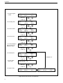
1
P
H
A
R
M
A
C
I
A
B
I
O
T
E
C
H
Electrophoresis Power Supply
EPS 3500
User Manual
19-3500-05
Edition AB
Pharmacia
Biotech
Important user information
Reading this entire manual is
necessary for full understanding
and safe use of this product.
The exclamation mark within an
equilateral triangle is intended to
alert the user to the presence of
important operating and
maintenance instructions in the
literature accompanying the
instrument.
The lightning symbol within an
equilateral triangle is intended to
alert the user to the risk of
exposure to high voltages.
Should you have any comments on this manual,
we will be pleased to receive them at:
Pharmacia Biotech AB
S-751 82 Uppsala
Sweden
Pharmacia Biotech reserves the right to make
changes in the specifications without prior notice.
Warranty and Liability
Pharmacia Biotech AB guarantees that the
product delivered has been thoroughly tested to
ensure that it meets its published specifications.
The warranty included in the conditions of
delivery is valid only if the product has been
installed and used according to the instructions
supplied by Pharmacia Biotech AB.
Pharmacia Biotech AB shall in no event be liable
for incidental or consequential damages,
including without limitation, lost profits, loss of
income, loss of business opportunities, loss of use
and other related exposures, however caused,
arising from the faulty and incorrect use of the
product.
Copyright© 1994 Pharmacia
Biotech AB
All rights reserved. No part of this publication
may be reproduced, stored in a retrieval system
or transmitted in any form by any means,
without permission in written form from the
company.
Contents
1. Introduction ............................................................................................. 3
2. Safety information .................................................................................. 4
2.1 Safety precautions ........................................................................ 4
2.2 In-built safety features ................................................................. 4
3. Unpacking and installation................................................................... 5
4. Technical description ............................................................................. 6
4.1 Front panel .................................................................................... 6
4.1.1 Display ................................................................................. 6
4.1.2 Keyboard ............................................................................. 6
4.1.3 Output sockets ................................................................... 8
4.2 Rear panel ...................................................................................... 8
5. Operation ................................................................................................. 9
5.1 Overview ....................................................................................... 9
5.2 Programming ................................................................................ 9
5.3 Running a program ................................................................... 11
5.4 Optional programming ............................................................. 13
5.5 Choosing run parameters ......................................................... 14
5.6 Short instructions ....................................................................... 16
6. Maintenance .......................................................................................... 17
7. Trouble shooting ................................................................................... 18
8. Technical specifications ........................................................................ 19
9. Ordering information .......................................................................... 20
2
1. Introduction
1. Introduction
The Pharmacia Electrophoresis Power Supply EPS 3500 is a high quality,
high precision and safe power supply for electrophoresis applications that
require a maximum of 3500 volts.
EPS 3500 is primarily designed for the following techniques:
●
●
DNA sequencing
IEF (Isoelectric focusing)
EPS 3500 is also suitable for:
●
●
SDS-PAGE (Polyacrylamide Gel Electrophoresis)
Native PAGE
●
Agarose electrophoresis
●
Electroblotting
DNA pulsed field electrophoresis
●
Electrophoresis separations can be controlled by voltage, current or power.
The EPS 3500 automatically switches over the controlling parameter
according to programmed limits and conductivity variations in the system.
Two electrophoresis units can be connected to the EPS 3500 and run with
the same programmed method at one time. Three programs can be saved.
3
2. Safety information
2. Safety information
2.1 Safety
precautions
Extreme caution should be exercised in the operation of this instrument as it
can develop sufficient voltage and current to produce a lethal shock.
To avoid any risk of injury, the instrument should only be operated by
properly trained personnel and always in accordance with the instructions
provided.
Read this entire manual before using this power supply.
1. This instrument is designed for indoor use only.
2. The instrument must always be used with the protective earth lead of the
power cord correctly grounded to earth at the mains outlet.
3. To permit sufficient cooling, ensure that the vents in the rear and sides of
the instrument are not covered.
4. Do not operate the instrument in extreme humidity (above 95%). Avoid
condensation by letting the unit equilibrate to ambient temperature when
taking the power supply from a colder to a warmer environment.
5. Keep the instrument as dry and clean as possible. Wipe regularly with a
soft damp cloth. Let the power supply dry completely before use. If
wetted, unplug the power supply until the instrument is dry.
2.2 In-built safety
features
6. Use only undamaged electrical wire and equipment specified for the
voltages you will use. High voltage wires must meet the requirements of
the IEC 1010-2-031: 1993 electrical standard.
Any electrophoresis equipment connected to the power supply should
meet the requirements of the IEC 1010-1:1993 electrical standard.
7. Note that the output is connected to the chassis/reference earth.
The EPS 3500 is designed in accordance with the IEC 1010 electrical safety
standard. The power supply also has several built-in safety functions. Error
messages are also shown on the display:
1. Functional earth leakage.
Should the power supply be connected to an electrophoresis unit that has a
leakage path to earth, the EPS 3500 will detect this fault and the high
voltage is turned off.
2. Start current check.
To ensure that an electrophoresis unit is connected correctly, the power
supply checks that the resistance is not higher than a specified limit at a low
safety voltage (<40V). If this resistance is too high, the voltage is turned off.
Too high a resistance can also be caused by using buffers with extremely
low conductivity. The high voltage is also turned off in this case and an
error message is shown. This function can be disabled to perform certain
applications (see 5.4 Optional programming).
3. Sudden load change detection.
This function prevents accidents under running conditions due to a break in
the electrical circuit such as a bad connection to the electrophoresis unit.
The high voltage is turned off in such an event.
4
3. Unpacking and installation
3. Unpacking and
installation
Unpacking
Check the contents against the packing list supplied. Inspect for any damage that may
have occurred during transit. Report any damage immediately to your local Pharmacia
representative and to the transport company concerned.
Mains connection
Select the appropriate voltage range, 100-120 or 220-240 V, see Fig. 2.
Warning!
If the power supply is connected to 220-240 V with the range set to
100-120 V, the instrument can be severely damaged.
Select the appropriate mains cable and connect one end to the mains socket on the EPS
3500 power supply, see Fig. 2, and the other end to an AC grounded outlet.
Local regulation for Great Britain
WARNING IMPORTANT
This appliance must be earthed.
The wires in the mains lead are coloured in accordance with the following code:
Green and yellow
Earth
Blue
Neutral
Brown
Live
If the plug provided is unsuitable for socket outlets, the plug must be cut off and
suitable plug fitted. The cut-off plug should be disposed of and must not be inserted
into any 13 amp socket as this can result in electric shock. The plug or adapter or the
distribution panel should be provided with 13 amps fuse. As the colours of the wires
in the mains lead of this appliance may not correspond with coloured markings
identifying the terminals in your plug, proceed as follows:
The green and yellow wire must be connected to the terminal in the plug which is
marked with the letter E or by the earth symbol, or coloured green, or green and
yellow.
The blue wire must be connected to the terminal which is marked with the letter N or
coloured black.
The brown wire must be connected to the terminal which is marked with the letter L
or coloured red.
Note:
After replacing or changing a fuse, the fuse cover in the plug must be
replaced with a fuse cover which corresponds to the colour of the insert
in the base of the plug or the word that is embossed on the base of the plug,
and the appliance must not be used without a fuse cover.
Only 13 Amps fuse approved to B.S. 1362 A.S.T.A. should be used.
Switch on the power. Each time the instrument is turned on a self diagnostic test is
done. If an error is detected during the test a message will appear on the display and
an alarm will sound.
Connection of the electrophoresis unit(s)
Connect the leads from the electrophoresis unit (red to red, and black or blue to blue),
see Fig. 1. The red lead is the positive and black or blue is the negative.
Use only undamaged electrical wire and equipment approved for the
voltage you will use.
Two electrophoresis units can be run simultaneously with the same program. Please
remember to double the limiting current and power if two electrophoresis units are
run at the same time. The voltage will be the same regardless of the number of units.
Warning!
5
4. Technical description
4. Technical description
4.1 Front panel
The front panel consists of an alphanumeric display, a keyboard with
9 membrane keys, a light emitting diode (LED) that lights when voltage is
applied (HV on) and connectors for two electrophoresis units.
4.1.1 Display
A 32 digit alphanumeric display guides you through the programming,
shows current parameter values during the electrophoresis and final
parameter values afterwards. It also asks questions and shows error
messages. The display has an upper and lower row.
Fig. 1 shows the display in the start position when power is switched on for
the first time. The mode (in this case SET) is shown in the upper row on the
left. The program number is in the center of the upper row. The number
shown is that of the previously entered program. As no program has yet
been entered, the first available program number, P1, is shown. The blinking
figure, in this case “1”, indicates that it can be changed by using the
keys. The upper right shows the programmed breakpoint. In this
case it is off.
The lower left, middle and right positions show voltage, current and power
respectively.
Fig. 1. The front panel of the EPS 3500.
4.1.2 Keyboard
enter
6
Enter
Enters a value, locks the value if correct, and moves programming to the
next field. Valid values are voltage 35-3500 V, current 1-150 mA,
power 1-100 W, time 0:01-500 h, volthours 1-500 000 Vh.
4. Technical description
set
Set
Puts the instrument into SET, its programming and starting mode. In the
set
RUN mode, pressing
also shows the programmed parameters for
set
the actual run. In addition,
allows you to make changes in the
program during a run after first pressing
pause
.
continue
Change up/Change down
Changes the parameter, value or other choice in the field which is blinking.
Numerical values are changed in an accelerating manner when a key is held
down. Clicking a key changes the value in preset increments. Parameters or
units (e.g. Vh) and YES/NO choices are changed with one key push. The
keys can also be used to switch between time and volthours in RUN, PAUSE
and END. The values scroll i.e. they automatically change from maximum
to minimum value or vice versa.
run
Run
Pressing
run
starts the run and puts the program into RUN mode. The
program number, current values for voltage, current and power are shown
on the display. The elapsed time or volthours are also displayed. Switch
between time and volthours with
pause
continue
Pause
Puts the instrument in PAUSE mode and switches off the voltage. The
display shows the status of the run at the time the key was pressed.
pause
continue
only operates in RUN mode. Time and integration values are retained.
In the pause mode,
set
can be used to make changes in the program.
Return to RUN mode by pressing
STOP
.
pause
continue
or by pressing
run
.
Stop
Stops the run and puts the instrument in END mode. The voltage is
switched off and the end parameters are displayed. Switch between time and
integrated voltage by pressing
pressing
STOP
. A run cannot be continued after
.
Continue by pressing
run
to run the same method again or pressing
set
to choose another program, program a new method or make changes in an
existing method.
7
4. Technical description
more
exit
More
You can disable the start current check that otherwise detects if the
resistance is too high and switches off the power. See Section 5.4.
Exit
Stops the execution of an operation, such as the entry of a value. Only
values/units that have already been confirmed by
enter
are retained.
Returns the instrument to the mode that was left or the start position in
SET.
4.1.3 Output sockets
There are two sets of output sockets to allow two electrophoresis units to be
connected and run at the same time, see Fig. 1. The voltage output is
0-3500 V. The negative output socket gives between 0 and –1750 V and the
positive gives between 0 and +1750 V.
4.2 Rear panel
The rear panel is shown in Fig. 2. On the rear panel there is:
1. A mains switch. Press in I to switch on the power to the power supply.
Press 0 to switch off the power.
2. A socket for the mains cable.
3. A switch for voltage range. The left position corresponds to 100-120 V
and the right to 220-240 V.
4. Fan vents.
Fig. 2. The rear panel of the EPS 3500
8
5. Operation
5. Operation
5.1 Overview
The operation of the EPS 3500 is described in the following sequence.
1. Programming or editing a method.
2. Running a method.
When the method is running, it can be interrupted (put in PAUSE mode) to
apply samples and/or change the program. During a run it is also possible to
look at the program settings.
Programming and running are discussed in more detail in the following two
sections.
Blinking characters are shown as bold characters.
5.2 Programming
Start position
When the power supply is switched on, the display shows the start position
in SET mode. The previous program set is shown and that program number
is blinking, for example:
SET:
3000 V
P1
50mA
OFF
20 W
(If the power supply is switched on for the first time, the breakpoint parameter and the alarm are off and the values for voltage, current, and power
are 35 V, 150 mA and 100 W respectively).
Choosing a program
Up to 3 programs can be entered. Press
shown on the display or use
Confirm with
enter
enter
to confirm the program
keys to choose another.
. The programming procedure can be followed step by
step in Fig. 3.
Setting voltage, current and power limits
The display will now flash for the set voltage limit. Using the
keys, select the maximum voltage desired for the run. Confirm
with
enter
. Repeat the same procedure for limiting current and limiting
power. Programmable values for voltage are 35-3500, current, 1-150 mA,
power, 1-100 W, time, 0:01-500 h, volthours, 1-500 000 Vh.
Setting break-point
Choose between manual break or automatic break. For automatic break,
choose breakpoint units in either Volthours (Vh) or time (h). Select the
correct unit or, for manual break, choose, “OFF” with
.
9
5. Operation
1. Choose Program
number
SET:
3000 V
P1
50 mA
OFF
20 W
Select by
Confirm by
2. Set Voltage limit
SET:
35 V
enter
P2
150 mA
OFF
100 W
Select by
Confirm by
3. Set Current limit
SET:
2500 V
enter
P2
150 mA
OFF
100 W
Select by
Confirm by
4. Set Power limit
SET:
2500 V
enter
P2
50 mA
OFF
100 W
Select by
Confirm by
5. Choose Breakpoint
unit (h or Vh) or no
Breakpoint (OFF)
SET:
2500 V
enter
P2
50 mA
OFF
30 W
Select by
Confirm by
6. Set Breakpoint
SET:
2500 V
enter
P2
50 mA
0 Vh
30 W
Select by
Confirm by
7. Choose Alarm
YES or NO
Breakpoint off
enter
Alarm at End ? Y
Select by
Confirm by
8. Program ready
SET:
2500 V
P2A
50 mA
enter
3000 Vh
30 W
SET:
2500 V
Fig. 3. Step-by-step summary of programming.
10
P2
50 mA
OFF
30 W
5. Operation
Confirm with
enter
.
If volthours or h (time) were chosen, the display will flash for the break
value. Set the value with
and confirm with
enter
.
Choosing alarm
When a breakpoint has been entered, the following question is shown:
Alarm at End ?
Y
Select YES or NO with
and confirm with
enter
. If YES is
selected, a small “A” appears on the right of the program number, i.e. 2A.
Back to start position
The program is now back to the start position in the SET mode with the
program number flashing. It is possible to go back to this position at any
stage during programming in SET mode by pressing
that the program is saved automatically when
exit
exit
or
STOP
. Note
is pressed.
Disabling the current check
See Section 5.4 if you want to use this feature.
5.3 Running a
program
Connect the leads from the electrophoresis unit (red to red, and black or
blue to blue). Red is positive and black or blue negative. Up to two
electrophoresis units can run at the same voltage at one time. Please
remember to double the maximum current and power conditions if two
units are to be run. Voltage will be the same regardless of how many units
are run. The current should also be doubled if two gels are run on the same
unit.
Choosing a program
Press
set
and select the program you wish to run by pressing
until the value after the “P” is correct. Confirm with
enter
.
(Omit this step if you have just programmed a method as described in
section 5.2.)
Running a program is described schematically in Fig. 4.
Running
Press
run
to start the electrophoresis. The display will show current
values for voltage, current, power and elapsed time or volthours. You can
switch between showing the elapsed time or volthours by
.
The limiting parameter will attain the programmed limit. The unit
for that parameter is underlined.
A light emitting diode shows when voltage is applied (HV on).
11
5. Operation
1. Choose Program number.
P1
SET:
3000 V 50 mA
OFF
20 W
Select by
SET:
P2A
2500 V 50 mA
2. Start the run.
run
Start by
RUN:
500 V
3000 Vh
30 W
P2A
6 mA
1 Vh
30 W
pause
set
A
SET:
P2
2500 V 50 mA
A
3000 Vh
30 W
RUN:
P2
1200 V 25 mA
500 Vh
30 W
continue
500 Vh
30 W
PAUSE:
P2A
1200 V 25 mA
exit
or wait 5 s
pause
continue
or
run
set
pause
continue
3. During a run you can view the
settings. It is also possible to interupt
the run and make changes in the
program.
P-SET:
P2A
2500 V 50 mA
or
exit
3000 Vh
30 W
Programming
4. Stop the run manually.
5. The run is stopped automatically.
RUN:
P2A
2500 V 10 mA
2500 Vh
25 W
END:
P2A
2500 V 9 mA
3000 Vh
23 W
END:
P2A
2500 V 50mA
STOP
2500 Vh
25 W
Fig. 4. Step-by-step summary of run and pause function
If no current is displayed, please check the electrical connections to the
electrophoresis equipment.
Pausing
You can interrupt the electrophoresis for sample loading and/or changing
parameter values by pressing
pause
continue
. Voltage and current will no longer be
supplied, the HV on LED goes off, and you may safely load your samples.
The display shows the status of the run when
pause
was pressed.
continue
Switch between time and integrated voltage by pressing
When sample loading is complete, press
pause
continue
again or
.
run
and the run will continue from where it was interrupted.
When in the PAUSE mode you can also press
set
to make changes in the
program. This mode is called the P-SET mode. When the P-SET mode is
12
5. Operation
entered you can make changes as described under programming. The P-SET
mode is the same as the SET mode apart from restrictions in setting the
breakpoint. Naturally, it is not possible to enter a time or volthour that is
already passed.
Press
exit
or
pause
continue
to go back from P-SET to PAUSE. Press
run
or
pause
continue
to proceed with the electrophoresis.
View programmed values
It is also possible to view the programmed values during a run by pressing
set
. Note that no values can be changed here. The display returns
automatically to show RUN values after 5s. Alternatively use
exit
or
run
.
Stopping the run and viewing end parameter values
When the programmed time or volthour is attained, the program will enter
the END mode. It is also possible to break the run manually by pressing
STOP
.
In both cases, the voltage, current and power will go to zero as indicated by
the HV on LED switching off. The end parameter values are displayed.
Switch between elapsed time and integrated voltage by
.
An alarm will sound if selected in the program. You can stop the alarm by
pressing
STOP
.
A run cannot be continued after pressing
STOP
.
Disconnect the leads and proceed with post-electrophoretic techniques.
Since diffusion will begin as soon as the voltage is turned off, you should
remove the gel and begin staining, blotting or autoradiography immediately.
5.4 Optional
programming
You can disable the start current check that otherwise checks that the
resistance is not higher than a specified limit. This disabling function is set in
the MORE mode instead of the SET mode in order not to confuse users who
do not need this feature, and for safety reasons.
The MORE mode is described in Fig. 5. After pressing more , the program
asks you for the program number and if you want to keep the start current
check.
Choose program number and change between “ YES ”and “ NO ” by
and confirm with
enter
. Choosing “NO” for start current check
means that the function is disabled and high voltage can be applied despite a
very high resistance. Leave the MORE mode by
Warning!
exit
.
By disabling the start current check, the power supply can
deliverhigh voltage even if it is not connected to
electrophoresis equipment.
13
5. Operation
1. Enter MORE
SET:
2500 V
P2A
50 mA
Select MORE by
2. Select program
3000 Vh
30 W
more
P2
MORE:
Select program
Select by
Confirm by
3. Choose current check no
enter
Current check at
start? YES/no
Select by
Confirm and
Exit by
4. Back to SET mode
SET:
2500 V
enter
P2A
50 mA
3000 Vh
30 W
Fig. 5. Disabling the current check.
5.5 Choosing run
parameters
EPS 3500 is an automatic cross-over power supply that allows the user to
set limits for voltage, current and power. During electrophoresis, only one of
the parameters is limiting at a time. The limiting parameter determines,
together with the conductivity in the electrophoresis system, the values for
the other two parameters. Voltage, current, power and conductivity are
related by the following equations:
U =I/L
(1)
P= UxI
(2)
Where U = Voltage, I = Current, P = Power and L = Conductivity
Equation (1) is more familiar if the conductivity is replaced by the reciprocal
resistance (R):
U=RxI
(Ohm’s law)
The electric field E, measured in V/cm, is the driving force behind
electrophoresis.
E = U/d
where E = Electrical field strength, U = Voltage, d = distance
The electrical field strength is achieved by applying a voltage. The higher the
voltage, the faster the electrophoresis. Fast electrophoresis is beneficial since
it counteracts diffusion.
The disadvantage of increasing the voltage too much is that most of the
generated electrical energy, the product of power and time, is transformed to
heat. Therefore cooling of electrophoresis equipment is recommended.
14
5. Operation
Cooling will also reduce “smiling” effects which are caused by mobility
differentials across an electrophoresis gel resulting from poor heat transfer.
Since the cooling efficiency cannot be increased indefinitely, the power
should be limited when programming the power supply.
The parameter that should be chosen as the constant and thus control the
electrophoresis depends on the type of electrophoresis. In the case of
homogeneous buffers throughout the system (same electrode and gel buffer),
the conductivity is constant during the electrophoresis. If the conductivity is
constant, the voltage will be proportional to the current and the power to
the square of the current, according to (1) and (2). This means that the
result of the electrophoresis will be the same, regardless which parameter is
chosen for constant. For historical and practical reasons, voltage is most
commonly used for regulation. Submarine gel electrophoresis of DNA/RNA
and pulsed field electrophoresis are usually run at constant voltage. SDSPAGE using continuous buffer systems is run at constant voltage or current.
For discontinuous buffer systems, the resistance will increase as the
electrophoresis proceeds due to a decrease in conductivity. Running at
constant voltage will result in decreasing current and power. Constant
voltage will thus be “safe” in the respect that the power will not increase
and produce more and more heat. On the other hand, the separation will
slow down and impair resolution due to an increased time available for
diffusion. Running at constant power would give a faster electrophoresis
and controlled power, while running at constant current would, at the first
sight, seem to be problematic because of increasing voltage and power.
During discontinuous electrophoresis, however, the voltage is not distributed
evenly across the gel. These gels have a region with low ionic strength that
causes a high electrical field strength. This region increases as the
electrophoresis proceeds. This means that the main part of the voltage is
spread over a longer and longer distance and a higher and higher power is
tolerated. This is the reason why constant current is chosen for such
applications. It is, however, recommended to also limit the power as a
precaution against overheating the gel. The power supply will probably
switch over to limiting power at the end of the run due to increased voltage.
The crossing-over between different parameters controlling the
electrophoresis can be illustrated by IEF (isoelectric focusing) using carrier
ampholytes. A graphical representation of the changes in power, voltage and
current that may occur during a typical IEF run is given in Fig. 6. Since the
pK values of the carrier ampholytes and the proteins are temperature
dependent, IEF must be carried out at a constant temperature. Therefore
cooling of electrophoresis equipment and controlling by power is recommended. The main part of the IEF is thus controlled by power (phase II).
The conductivity is gradually decreasing because the carrier ampholytes and
sample will loose their net charge during the build up of the pH gradient.
Thus the current will decrease and the voltage increase at constant power.
During the early stage of the formation of the pH gradient it is important to
limit the current. Otherwise the gradient will be irregularly shaped (phase I).
The conductivity is not constant along the gel so it is important to also limit
the voltage. This means running at constant voltage for the last phase (phase
III) to prevent local overheating.
For detailed information about parameter values, always follow the gel
supplier’s recommendations.
15
5. Operation
I
II
a
Volt
III
Power
IV
ge
Cu
rre
nt
Preset time
Alarm
Fig. 6. Power fluctuations which occur during a typical IEF run.
5.6 Short
instructions
This section summarizes the main points covered earlier in this chapter.Use
it as a check list once you are familiar with the detailed programming and
running instructions. Refer also to the separate schematic operating guide
included with the power supply. We recommend you keep this schematic
guide close by the instrument.
1. Turn mains power ON. The display should have the program number
flashing.
2. Press
enter
for the actual program number, or use
select the program number desired. Press
enter
to
.
3. For each of the parameters Voltage, Current and Power, press
enter
until the value desired is reached. Confirm by pressing
after each
one, and the display will automatically move to the next parameter.
4. Choose between manual break or automatic break. For automatic
break, choose breakpoint units in either Volthours (Vh) or time (h).
Select the correct unit or, for manual break, choose “OFF” with
enter
. Confirm with
.
5. If volthours or time were chosen, set the value to be used for the
breakpoint with
and
enter
.
6. If an automatic breakpoint was chosen under 4, you will be asked if
you wish an alarm to sound at the end of the run. Select YES or NO
with
and press
enter
. If YES was chosen, this is indicated
by a small A as in “1A” to the right of the program number in the
display.
16
5. Operation, 6. Maintenance
7. When programming is completed, connect your electrophoresis unit to
run
the outputs, and press
.
8. The actual voltage, current and power are shown on the display
together with the elapsed time or volthours (switch with
9.
pause
continue
).
can be used to interrupt and then continue the run.
10. The programmed parameters can be checked during the run by pressing
set
.
11. The programmed run stops automatically or by pressing
STOP
.
6. Maintenance
Check regularly that the fan is working properly. Wipe the instrument
regularly with a damp cloth. Let the instrument dry completely before use.
Otherwise no user maintenance is necessary. All servicing should be
entrusted to qualified personel only. Please contact your local Pharmacia
representative for more service information.
17
7. Trouble shooting
7. Trouble shooting
If an error that can be corrected by the user occurs, either during a run or
when switching on the power supply, the program enters the HALT mode
and the output is switched off. Four different types of errors can cause
HALT. The following list shows the error message on the display, the cause
and the remedy.
Error message
Cause
Remedy
The current is less than the lower limit.
This can be due to incorrect
connection of the electrophoresis
equipment or due to use of buffers with
extremely low conductivity.
1. Check connections and/or buffers.
HALT: Ground
leakage current
The current to ground leakage in the
electrophoresis unit is too high.
Check the electrophoresis unit.
HALT: Mains
Voltage too low!
The mains voltage is too low, see
Specifications.
Check voltage selector.
Check mains voltage.
HALT: Mains fail
Program stopped
Mains power failure for more than 7 s.
Press
HALT: Low start
current!
2. Press
more
, switch off the start
current check in the MORE mode.
IMPORTANT! Read Section 5.4 first.
pause
continue
to continue
running a program or
STOP
to
interrupt the run.
If a serious error occurs, the program enters the FAIL mode. The output is
switched off and an error message is shown in the display.
FAIL:Code No: xxx
Call service
Please read the error code number and contact your Pharmacia LKB
Biotechnology representative.
18
8. Technical specification
8. Technical specifications
Regulation
Maximum voltage, current and power with automatic cross-over
at preset limits
Output range
Voltage: 0-3500 V DC,
Current: 0-150 mA
Power: 0-100 W
Programming range
Voltage: 35-3500 V DC
Current: 1-150 mA
Power: 1-100 W
Time: 00:01-500 h
Volthour: 1-500 000 Vh
Output resolution
Voltage: 1 V
Current: 100 µA, 0-14.9 mA
1 mA, 15-150 mA
Power: 1 W
Programming resolution
Voltage: 5 V
Current: 1 mA
Power: 1 W
1 min, 00:01-99:59,
Time:
1 h, 100-500 h
Volthour: 1 Vh, 1-9999 Vh,
100 Vh, 10.0-99.9 kVh
1 kVh, 100-500 kVh
Accuracy
Voltage: 1%, ± 5 V
Current: 1%, ± 1 mA
Power: 2%, ± 1 W
Timer:
0.1% ± 1 min, 00:01-99:59 h
0.1%, ± 10 min, 100-500 h
Line regulation
< 0.2%
Load regulation
< 1% at load change 10-90% of maximum load
Ripple
<1 % at 3500 V
Short term stability
< 0.2%/10 h after warm up
Long term stability
<1%/year
Start current check
Resistance not greater than 1 ΜΩ at 40 V
(current less than 40 µA). Can be disabled
Sudden load change check
Ground leakage check
Leakage not greater than 500 µA
Output protection
Fully protected against any overload conditions
Recovery after power failure
Duration <8 s, The program continues automatically
Duration > 8s, The program continues after manual restart
Ambient operating temperature
4-40 °C
Ambient operating humidity
0-95%
Ambient operating pressure
106-84 kPa (corresponds to 0-2000 m)
Mains requirements
100-120 V/220-240 V; 50/60 Hz
Power consumption
Max 140 W
Dimensions (WxDxH)
250 x 385 x 95 mm
Weight
4.7 kg
19
9. Ordering information
9. Ordering information
20
Designation
Code No.
Electrophoresis Power Supply - EPS 3500
19-3500-00
Printed in Sweden by HMP AB TK i Uppsala, August, 1994
Pharmacia
Biotech