1
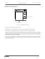
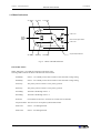
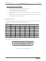
witch owe twork PPow Neetwork weerr SSwitch Liebert NPS Network Power Switch HOT SWAP Installation and User Manual Manual Reference: 6390060O-En (03/04) Rev ENPAu 05/2004 Dear Customer, Please accept our thanks for giving us the privilege to serve you by choosing a Liebert make product. If this is your first Liebert product, we hope it is the beginning of a long relationship which delivers value to your organisation. If you already own and use a Liebert product, we are doubly honoured by your decision of continuing this relationship. It is our constant endeavour to partner you for the growth and success of your business. This philosophy is reflected in our Mission statement “To deliver value through Air & Power Quality solutions to achieve customer delight”. Please do give us feedback to help us realize our Mission. EMERSON NETWORK POWER ENGLISH This manual describes installation and operation procedures for the Network Power Switch. All relevant parts of the manual should be read prior to commencing installation. If you encounter any problems with the procedures contained in this manual you should seek immediate assistance from the Liebert Sales Office from whom the equipment was purchased. Alternatively, contact the Liebert's Customer Service & Support department at the address shown below: Emerson Network Power Ltd - United Kingdom Fourth Avenue, Globe Park Marlow Buckinghamshire SL71YG United Kingdom Telephone +44 1628 403 200 Fax +44 1628 403 203 Liebert HIROSS Services (HQ) Customer Service and Support Department Via Leonardo da Vinci 8 35028 - Piove di Sacco (PD) Italy Help Desk Telephone +39 049 9719111 Fax +39 049 9719045 [email protected] Please visit our web site: http://ups.liebert-hiross.com/ While every precaution has been taken to ensure accuracy and comleteness in this manual, Liebert Corporation assumes no responsibility and disclaims all liability for damages resulting from use of this information or for any errors or omissions. Liebert Corporation pursues a policy of continual product development and reserves the right to change the equipment design without notice. Copyright 2004 by Liebert Corporation. Unauthorized reproduction prohibited All rights reserved. (03/04) Page i USER MANUAL Network Power Switch Safety Precautions CONFORMITY AND STANDARDS This equipment complies with the following requirements: Normative references: Safety: * EN 50178 EMC: * EN61000-6-2 (2001-10;immunity) * EN61100-6-3(emission) The equipment must be installed in accordance with these instructions and used only with accessories approved by the manufacturer to maintain conformity with the standards. WARNING Follow these instructions scrupulously: The NPS is designed exclusively for indoor use. Protect the unit from excessive condensation and install it in a place free of flammable liquids, gases and corrosive substances. The Network Power Switch must be commissioned and serviced by an engineer approved by the manufacturer (or his agent). Failure to do so could result in personnel safety risk, equipment malfunction and invalidation of warranty. Personnel working with the equipment described in this manual must be thoroughly familiar with the product. Obtain appropriate protection against input overcurrents on the basis of the unit’s nominal power. Before making connections rear the unit, make sure that all incoming power sources are de-energised and insulated. The unit is powered by more than one power mains. As with other types of power equipment, dangerous voltages are present within the Network Power Switch enclosure. No risk exists to any personnel when operating the equipment in the normal manner, following the recommended operating procedures. General The unit must be grounded in accordance with current electrical regulations. Guide to the Instructions The warning triangle indicates all the personal safety instructions. Follow these instructions carefully to avoid injury. Page ii (03/04) USER MANUAL Network Power Switch Table of Contents 1 Chapter 1 – General description ............................................................................................................................... 1-1 1.1 1.2 1.3 1.4 1.5 1.6 Introduction ............................................................................................................................................................... 1-1 Design Concept......................................................................................................................................................... 1-2 Mechanical Design Description................................................................................................................................ 1-3 Mimic Indications ..................................................................................................................................................... 1-4 Manual Bypass Switch Operation ............................................................................................................................ 1-5 Potential free contacts ............................................................................................................................................... 1-6 2 Chapter 2 – Operating Instructions........................................................................................................................... 2-1 2.1 2.2 2.3 2.4 2.5 Introduction ............................................................................................................................................................... 2-1 General Notes............................................................................................................................................................ 2-1 Procedure for Switching the Network Power Switch to power the load from a Power Off condition................... 2-1 Switching the Load to Manual Bypass condition..................................................................................................... 2-2 Procedure for switching the Network Power Switch from Manual Bypass condition to Normal Operation......... 2-2 3 Chapter 3 – Installation Procedure ........................................................................................................................... 3-1 3.1 Introduction ............................................................................................................................................................... 3-1 3.2 Equipment positioning and environmental considerations ...................................................................................... 3-1 3.3 Connecting cables to Network Power Switch .......................................................................................................... 3-2 3.3.1 Cable entry ....................................................................................................................................................... 3-2 3.3.2 Cable Rating..................................................................................................................................................... 3-2 3.3.3 Cable connections ............................................................................................................................................ 3-2 3.3.4 Safety earth....................................................................................................................................................... 3-2 3.3.5 Protective devices............................................................................................................................................. 3-3 3.3.6 Cabling Procedure............................................................................................................................................ 3-3 4 Chapter 4 - Specifications......................................................................................................................................... 4-1 4.1 4.2 4.3 4.4 4.5 Conformity and Standards ........................................................................................................................................ 4-1 General Specifications .............................................................................................................................................. 4-1 Environmental specifications.................................................................................................................................... 4-1 Electrical Specifications............................................................................................................................................ 4-2 Mechanical specifications......................................................................................................................................... 4-2 5 Installation Drawings ................................................................................................................................................ 5-1 5.1.1 5.1.2 5.1.3 5.1.1 5.1.2 5.1.3 6 Power Circuit Diagram .................................................................................................................................... 5-1 External Power cable connections ................................................................................................................... 5-1 Overall general arrangement............................................................................................................................ 5-1 Power Circuit Diagram .................................................................................................................................... 5-2 External Power cable connections ................................................................................................................... 5-3 Overall general arrangement............................................................................................................................ 5-4 LIMITED WARRANTY.......................................................................................................................................... 6-1 (03/04) Page iii USER MANUAL Network Power Switch This manual describes the following equipment: EQUIPMENT PART NUMBER 6 kVA Pole Network Power Switch SSWITCH-25A Important Support Information: If you require assistance for any reason, please have the following information available: Model and size Serial number Date installed Location Voltage & Frequency Page iv (03/04) User Manual Chapter 1 - General Description Network Power Switch 1 Chapter 1 – General description 1.1 Introduction The Network Power Switch is an automatic static transfer switch designed to provide fast automatic transfers between two independent, synchronous AC power sources to provide continuity of AC power to critical equipment, such as information technology equipment. One of the two AC inputs is designed as the “preferred” source to which the Network Power Switch will connect the load as long as the designated input source is within the acceptable limits, the Network Power Switch is designed to transfer the output load to the “alternate “input source, as long as the alternate source is within the acceptable voltage limits. The Network Power Switch provides fast, break-before-make transfers to prevent interconnection of the two sources, even under faulted source conditions. The maximum sense and transfer times are within the tolerance of IEEE Standard 446 susceptibility curve for information technology equipment to allow uninterrupted load equipment operation. In case of overload, Network Power Switch gives the alarm. Under Short-circuit condition a fast acting semi conductor fuse protects condition of the load. Manual Bypass Switch The entire power static switch module is hot swappable. Before removing this module the load is transferred, without break to any one of the source directly by using the Manual bypass switch. After replacing the static switch module, the load is restored on static switch module, using the Manual bypass switch. Block Diagram L1 BYP. MAN. BYP. SW L1 LINE SIDE ST. SW. L2 L2 BYP. OUTPUT N2 BYP. MAN. BYP. SW N1 N2 NEUTRAL SIDE ST. SW. N2 BYP. NETWORK POWER SWITCH Fig 1.1 – Block Diagram of Network Power Switch (03/04) Page 1-1 Chapter 1 - General Description User Manual Network Power Switch 1.2 Design Concept Figure 5.1.1 in Chapter 5 shows the Power circuit diagram for Network Power Switch. Source 1 & Source 2 are the two synchronized power sources with fuse switches FS1 & FS2 & pair of SCR’s TA1 & TB1 in series with each path &TA2 and TB2 in the neutral path Logic dictates that at any time only one pair of back-to-back connected SCR’s in the line and neutral should conduct. This routes the input power to the output load. Should the load feeding source fail due to any reason; the other source takes over automatically in less than 6 ms. This ensures that the critical load always receives the power & changeover time is less than the tolerance limit set by IEEE 446 (CBEMA curve) for information technology equipments. The change over is always with break, which ensures that in no case two sources get paralleled. Priority source can be selected through front panel switch. The live mimic on front panel indicates which source is on priority & which is feeding the load. Figure 1.4 shows the details of live mimic panel. Page 1-2 (03/04) User Manual Chapter 1 - General Description Network Power Switch 1.3 Mechanical Design Description FIXED UNIT HOT SWAPPABLE UNIT Fig 1.3 – Hot swappable and Fixed Unit The Network Power Switch consists of two modules. Fixed module consists of the input and output connections and manual bypass transfer control switch. Second module is hot swappable plug-in type with removable electronics & static switching module. The bypass / transfer control switch is located on right side of the cabinet with a key lock to restrict access to qualified or designated operators. The plug in module likewise contains locked latches to prevent unauthorized removal of the module. The Network Power Switch is designed to allow replacement of the removable electronics /switching module without having to de-energize the load equipment. Entire power static switch module is hot swappable. Before removing this module the load is transferred without break to any one of the source directly. After replacing the static switch module, the load is again transferred back to Network Power Switch without break. (03/04) Page 1-3 Chapter 1 - General Description User Manual Network Power Switch 1.4 Mimic Indications S1 Healthy S1 Priority S1 Feeding Load on S1 Priority Selection Switch OverLoad on Super Switch Load on S2 Unsynchronised transfer S2 Healthy S2 Priority S2 Feeding Fig 1.4 – Mimic and LED Indications LED INDICATION Mimic indications: Ten LEDs are mounted on the mimic plate; Glowing LED’s indicate the status of the Network Power Switch. S1 Healthy: Source –1 is a healthy source and is well above the 10% under voltage setting. S2 Healthy: Source –2 is a healthy source and is well above the 10% under voltage setting. S1 Priority: The priority selector switch is on S1 priority position. S2 Priority: The priority selector switch is on S2 priority position. S1 Feeding: The load is fed through source –1. S2 Feeding: The load is fed through source -2. Overload: Overload has occurred i.e. current level crossed 110% of full load. Unsynchronized: The sources are out of phase-synchronized window. Load on S1: Source –1 is feeding the load. Load on S2: Source –2 is feeding the load. Page 1-4 05/2004 Rev ENPAu User Manual Chapter 1 - General Description Network Power Switch 1.5 Manual Bypass Switch Operation BYPASS ON S1 SOURCE YELLOW LED (LOAD ON S1) OUTPUT YELLOW LED (LOAD ON S2) BYPASS ON S2 SOURCE Fig 1.5 – Manual Bypass Switch Operation Manual Bypass switch is used only when a fault occurs in the Network Power Switch and the control circuitry of the Network Power Switch is to be checked. For doing this operation the load is connected to the bypass. For Normal Operation, the position of the switch should be at Network Power Switch output position (i.e. horizontal) If the load is to be fed through the source 1 Bypass, first it is to be unlocked and the knob should be rotated upwards. To feed through source 2 bypass the knob is to be rotated downward. A mechanical interlocking arrangement is provided on this Bypass switch, by which the Hot swappable unit can be removed only when load is connected to bypass. In normal operation when the load is connected to Network Power Switch, the Hot swappable unit cannot be removed. Operating Network Power Switch in Normal Mode (load connected to Network Power Switch output) • Unlock the Manual Bypass Switch with the key provided. • Depending upon the available healthy source (i.e. either Source-1 or Source-2 ) select it by changing the Manual Bypass Switch position. • Unlock the sliding module • Pull out the Hot swappable sliding module out of the Network Power Switch, which contains (SCR assembly, control circuitry). (03/04) Page 1-5 Chapter 1 - General Description User Manual Network Power Switch Operating Network Power Switch in Bypass mode • Insert the Hot swappable module into the Network Power Switch unit • Lock the sliding module for preventing its accidental opening. • Unlock the Manual Bypass Switch with the key provided • Connect the Load output to Network Power Switch by changing the switch position to Network Power Switch output. • Depending on the priority switch, Load will get transferred to source-1, if the priority switch is on source1. • The Static Switch output position LED will glow 1.6 Potential free contacts The Network Power Switch status can be checked with the 37 pin D-type connector, located on the rear end. This is a potential free contact, and gives following indications as shown in Table 1-1 – Table 1-1 Status Termination available of 37 pin D-type connector NC NO Common NC NO Common Overload 20 1 2 3 21 19 Priority 23 4 5 6 24 19 S1 Feed 7 25 26 27 8 19 S1 Healthy 28 9 10 11 29 19 S2 Healthy 12 30 31 32 13 19 S2 Feed 33 14 15 16 34 19 Unsynch 17 35 36 37 18 19 The pin details for this connector is shown in fig 1.6 19 18 17 16 15 14 13 12 11 10 9 8 7 6 5 4 3 2 37 36 35 34 33 32 31 30 29 28 27 26 25 24 23 22 21 20 Fig 1.6 – Pin details for 37 pin D-type Connector Page 1-6 (03/04) 1 User Manual Chapter 2 – Operating Instructions Network Power Switch 2 Chapter 2 – Operating Instructions 2.1 Introduction The Network Power Switch can be considered to be in one of the three operating conditions: • Normal Operation - All relevant power switches and fuses closed and the Load is connected to Network Power Switch output • Manual Bypass – The load is connected to the input supply directly. • Shut down - All power switches are off and load is not operational. 2.2 General Notes NOTE: All users controls and indicators mentioned in these procedures are identified in chapter1 For power connection details, refer to figure in Chapter 5. 2.3 Procedure for Switching the Network Power Switch to power the load from a Power Off condition This procedure should be followed when turning on the Network Power Switch from a fully powered down condition -i.e. When the load is not being initially supplied at all. It is assumed that the installation is complete; the authorized personnel have commissioned the system. 1. Select the priority to source1. Close the fuse FS1. 2. Check for the LED S1 healthy, S1 priority, S1 feed and LED load on source1 to glow. 3. Close the fuse FS2. 4. Check for the LED S2 healthy to glow. 5. Using priority switch transfer the load to source2, check this transfer does not affect the load. 6. Transfer the load to source 1 again and check this transfer does not affect the load. (03/04) Page 2-1 Chapter 2 – Operating Instructions User Manual Network Power Switch 2.4 Switching the Load to Manual Bypass condition BYPASS ON S1 SOURCE YELLOW LED (LOAD ON S1) OUTPUT (NOT CONNECTED) YELLOW LED (LOAD ON S2) ‘ON’ BYPASS ON S2 SOURCE (LOAD CONNECTED TO THIS BYPASS) Fig 2.2 – Switching to Bypass WARNING This operation should be performed by Trained personnel only. SWITCH TO YELLOW LED ‘ON’ POSITION ONLY. 1. By seeing the LED indication check which source is feeding. 2. Unlock the Bypass switch lock by the using the key provided. 3. Rotate the Manual Bypass switch in the direction of the source feeding the load as per the warning given on the mimic. 4. Relock the Bypass switch, remove the key and keep it in original place. 2.5 Procedure for switching the Network Power Switch from Manual Bypass condition to Normal Operation 1. Unlock the Bypass switch using the key provided. 2. Rotate the bypass switch knob to the Static switch output position, i.e. horizontal position. 3. Lock the Bypass Switch, remove the key and keep it in original place. Page 2-2 (03/04) User Manual Chapter 3 - Installation Procedure Network Power Switch 3 Chapter 3 – Installation Procedure 3.1 Introduction WARNING Do not apply electrical power to the Network Power Switch equipment before the arrival of the commissioning engineer. WARNING The Network Power Switch equipment should be installed by a qualified engineer in accordance with the information contained in this chapter and the drawing package shipped inside UPS cabinet. This chapter contains information regarding the positioning and cabling of the Network Power Switch. Because every site has its peculiarities, it is not the aim of this chapter to provide step-by-step installation instructions, but to act as a guide to the general procedures and practices that should be observed by the installing engineer. 3.2 Equipment positioning and environmental considerations The Network Power Switch cabinets are designed to fit in standard 19-inch rack. In case of non-availability, it can be kept on floor or as a tabletop item, with sufficient ground clearance. The super switch module should be located in a cool, dry, clean environment with adequate ventilation to keep the ambient temperature within the specified operating range. WARNING The Network Power Switch cabinet is connected with live voltages, hence it should be located at safe place. (03/04) Page 3-1 Chapter 3 - Installation Procedure User Manual Network Power Switch 3.3 Connecting cables to Network Power Switch WARNING BEFORE CABLING-UP THE NETWORK POWER SWITCH, ENSURE THAT YOU ARE AWARE OF THE LOCATION AND OPERATION OF THE EXTERNAL ISOLATORS THAT CONNECT THE NETWORK POWER SWITCH INPUT SUPPLY TO THE MAINS DISTRIBUTION PANEL. CHECK THAT THESE SUPPLIES ARE ELECTRICALLY ISOLATED, AND POST ANY NECESSARY WARNING SIGNS TO PREVENT THEIR INADVERTENT OPERATION. 3.3.1 Cable entry Cable enter the Network Power Switch cabinet, from the rear side as shown in figure 5.1.2. The cables are terminated on the connectors and fuses. 3.3.2 Cable Rating Following are the recommended cable size for 6kVA Network Power Switch – Table 3-1 Description Input Cables Output Cables Earthing Max. Current rating (Amp) 25 25 - PVC cable (sq.mm) 4 4 2.5 Note: These recommendations are for guideline purposes only and may be superseded by local regulations and codes of practices. 3.3.3 Cable connections Following are the set of external power cables, which are connected to the Network Power Switch equipment – • • • • • • • Input source 1 – Line Input source 2 – Line Input source 1 – Neutral Input source 2 – Neutral Output – Line Output – Neutral Earthing These cables are connected to the terminals on rear side of the equipment as shown in figure 5.1.2 in Chapter 5. 3.3.4 Safety earth The safety earth busbar is provided on the rear side of equipment .The safety earth cable must be connected to this busbar. WARNING FAILURE TO FOLLOW ADEQUATE EARTHING PROCEDURES CAN RESULT IN ELECTRIC SHOCK HAZARD TO PERSONNEL, OR THE RISK OF FIRE, SHOULD AN EARTH FAULT OCCUR. Page 3-2 (03/04) User Manual Chapter 3 - Installation Procedure Network Power Switch 3.3.5 Protective devices For safety reasons, it is necessary to install external to the Network Power Switch system, circuit breaking protective devices in the input a.c. supply and towards the output. Given that every installation has its own characteristics, this chapter provides general useful information for qualified installation engineers, with knowledge of operating practices, of regulatory standards, and of the equipment to be installed. Rectifier and Bypass input supply of the Network Power Switch: The input to Network Power Switch should be given through a 32 amp, 2pole ELCB for safe operation. Protection against excessive overcurrents and short circuits in the mains supply input: These inputs must be protected, installing suitable protective devices at the distribution panel of the incoming main supply, considering that the protection should discriminate with overload capacity of the system. The protective devices must be selected for the nominal input current, with respect to the rating and the input a.c. supply voltage as given in table 3-1. Protection against earth faults (RCD or RCCB devices): In the event of a differential (RCD) device being installed upstream of the input supply, one must take into account the transient and steady state earth leakage currents that are produced during start-up of the Network Power Switch. The presence of an RFI suppression filter inside the NPS, determines a residual earth current not greater than 3.5 mA. Residual current circuit breakers (RCCB/RCD) must be sensitive to d.c. unidirectional pulses (class A) in the network and insensitive to transient current pulses. They are identified by the symbols respectively: These isolators must have an average sensitivity, possibly adjustable between 10mA and 0,3A. It is recommended that the selectivity with every differential switch be verified both upstream of the input distribution board and downstream (towards the load). Output of the System: In the eventuality that an external distribution panel is used for load distribution, the selection of protective device must provide discrimination with those that are used at the input to the Network Power Switch module. 3.3.6 Cabling Procedure The external power cables should be connected to the terminals as shown in figure 5.1.2 in Chapter 5. Proper termination labels are provided near each connector for ease of cabling. (03/04) Page 3-3 Chapter 3 - Installation Procedure User Manual Network Power Switch This page is left blank intentionally Page 3-4 (03/04) User Manual Chapter 4 – Specifications Network Power Switch 4 Chapter 4 - Specifications 4.1 Conformity and Standards This equipment complies with the following requirements: Normative references: Safety: * EN 50178 EMC: * EN61000-6-2 (2001-10;immunity) * EN61100-6-3(emission) The equipment must be installed in accordance with these instructions and used only with accessories approved by the manufacturer to maintain conformity with the standards. 4.2 General Specifications • • • • • • • • • • • Manual and Automatic Transfers Sense and transfer time – less than 6 milliseconds Break-Before make switching Selectable preferred source Selectable auto/manual retransfer In-phase transfer window – adjustable from 7.5 ± 1° Convection cooling Hot swappable electronic static switching module Live mimic on Hot swappable unit for indicating load supply status & alarms Make before break manual bypass switch to transfer load from static switch to direct source 1 or source 2 Isolated neutrals 4.3 Environmental specifications ENVIRONMENTAL CHARACTERISTICS UNITS DESCRIPTION Heat dissipation W 75 Storage temp. range °C -40 to 60°C Operating temp. range °C 0 to 40°C Relative humidity % 0 to 95% Operating altitude m Up to 1500m (5,000 ft) Storage / Transport Altitude m Up to 12000m (40,000 ft) Audible Noise db < 45 db at 1.5 m (03/04) Page 4-1 Chapter 4 – Specifications User Manual Network Power Switch 4.4 Electrical Specifications ELECTRICAL CHARACTERISTICS UNITS DESCRIPTION VAC Amps 220, 230 or 240 volts single phase a.c., 2W+G, 50 Hz. Solidly grounded power sources 25 Hz 50 / 60 Source unhealthy status - Guaranteed Transfer to alternate source –15 % of V nominal Load Power factor range - 0.5 to unity leading or lagging Load Crest factor - Up to 3.5 In-Phase transfer window - Adjustable from 5 ± 1º Source voltage distortion % Up to 10% THD Overload capability % 125% of continuous current for 2 hrs, 1000% for two cycles minimum. Over current Protection - By semi conductor fuse Short circuit withstand capability Amps Up to 20,000 symmetrical amps, protected by internal fusing. Redundant Control Power supplies - Taken from available source 1 and source 2 Integral Maintenance Bypass - Make before break operation Alarm contacts - Nominal Input Voltage Power supply Nominal Output current Frequency Eight Isolated Normally Open alarm & static switch Status contacts. 6 milllisec for synchronized transfer and 16 millisec for unsynchronized transfer. Unsynchronised transfer 4.5 Mechanical specifications MECHANICAL CHARACTERISTICS DESCRIPTION UNITS Height Width 88.0 431.0 mm Depth Weight 457.0 8.0 kg Colour Matt Black Installation Cable entry Page 4-2 19” Rack Mounted / floor / table top - Rear side (03/04) User Manual Chapter 5 – Installation Drawing Network Power Switch 5 Installation Drawings 5.1.1 Power Circuit Diagram 5.1.2 External Power cable connections 5.1.3 Overall general arrangement (03/04) Page 5-1 Chapter 5 – Installation Drawing User Manual Network Power Switch 5.1.1 Power Circuit Diagram RC SNUBBER SOURCE 1 198V~220V AC,50Hz/60Hz 4 FS R1 C1 1 30 L1 X1 50A SWITCH FUSE C5 N1 32 X6:3 X3 C2 R2 X5 3 5 1 7 22 L2 X2 20 11 C1 R3 C6 7 018 X6:4 X4 C4 R4 7 022 N2 020 2 5 1 3 6 021 26 10 L1 8 N1 L2 08 7 CN7 3 1 CN2 15 28 A 16 3 17 1 19 18 3 CN1 1 CN3 20 3 39 21 1 CN4 B 22 3 1 CN6 33 CN11 S1 HEALTHY LD3 S1 PRIORITY LD9 S2 HEALTHY LD1 S1 FEED 6 LD10 S2 PRIORITY 7 LD4 OVER LOAD LD2 S2 FEED LD11 UNSYNC 2 6.8V DC 3 CN1,CN3,CN13,CN12 4 CN6,CN4,CN14,CN15 CN11 CN5 CN8 CN5 5 8 9 SUPER SW ITCH CONTROL PCB 100220012001 015 CN12 CN13 CN14 CN15 3 3 3 3 1 016 (03/04) 017 1 018 019 1 020 021 1 022 PCB - MIMIC LD8 1 CN7 CN2 NETWORK POWER SWITCH CONTROL PCB #100220012001 Page 5-2 34 1 1 N2 07 3 3 SOURCE 1 INPUT SOURCE 2 INPUT GATE CATHODE CONTROL WIRES FOR S.C.R. MODULE TA GATE CATHODE CONTROL WIRES FOR S.C.R. MODULE TB OUTPUT CURRENT SIGNAL LED INDICATIONS PRIORITY SWITCH POTENTIAL FREE CONTACTS OF STATUS RELAYS X6:2 B1 019 4 TB2 MOV 6 8 38 OUTPUT OUTPUT 3 L1-2 38 1 6 017 MOV 5 31 MOV 3 MOV 1 B3 12 B2 X6 016 2 5 OUTPUT MOV 2 015 4 1 50A SWITCH FUSE L1-1 SW1 (MANUAL BYP. SWITCH) 6 21 1 MOV 3 C3 36 3 TA2 29 36 27 19 2 5 1 X6:1 A2 A1 4 TB1 EMI FILTER PCB A3 CT 6 17 2 2 N2 6 N1 FS SOURCE 2 7 18 MOV 4 7 3 198V~220V AC, 50Hz/60Hz MOV 1 MOV 2 16 2 5 1 9 15 4 TA1 2 10 2 CN8 1 12V DC 38 37 PRIORITY SWITCH SW2 Chapter 5 – Installation Drawing Network Power Switch External Power cable connections Input Fuse 2 O/p Neutral O/p Line I/p Neutral - 2 I/p Neutral - 1 I/p Line - 2 I/p Line - 1 5.1.2 External Cables Input Fuse 1 Snap-on Connector Earthing Rear View EXTERNAL POWER CABLE CONNECTIONS NETWORK POWER SWITCH (03/04) Page 5-3 Chapter 5 – Installation Drawing User Manual Network Power Switch 5.1.3 Overall general arrangement 76 mm 88 mm 457 mm 431 mm Liebert NPS HOT SWAP Networ k Power Switc h 465 mm 483 mm Page 5-4 (03/04) User Manual Network Power Switch 6 LIMITED WARRANTY Liebert Corporation extends the following LIMITED WARRANTY to the purchaser and to its customer (collectively referred to as the "Purchaser"): the enclosed Power Protection System (Liebert NPS) and components are free from defects in materials and workmanship under normal use, service, and maintenance FOR A PERIOD OF TWO YEARS FROM THE DATE OF ORIGINAL PURCHASE from Liebert or the Liebert dealer or retailer. THE FOREGOING WARRANTY IS THE ONLY WARRANTY GIVEN AND NO OTHER WARANTY IS PROVIDED, EXPRESS OR IMPLIED, INCLUDING WITHOUT LIMITATION, MERCHANTABILITY OR FITNESS FOR A PARTICULAR PURPOSE. Certain aspects of disclaimers are not applicable to consumer products acquired by individuals and used for personal, family, or household purposes (as distinguished from industrial or other purposes). Local laws may not allow limitations on how long an implied warranty lasts, so the above limitation may not apply to you. This warranty gives you specific legal rights, and you may have other rights which vary according to local law. Certain repairs or services are the responsibility of the Purchaser and the Purchaser is expected to pay for them. This warranty does not extend either to products with removed or altered serial numbers or to any losses or damages due to act of God or source external to the product, misuse, accident, abuse, neglect, negligence, unauthorized modification, alteration, or repair, use beyond rated capacity, or improper installation, maintenance, application or use, including, without limitation, use in a manner contrary to the accompanying instructions or applicable codes. If the Liebert NPS fails to conform with the above warranty within the two year warranty period, Liebert will repair or replace the system, at Liebert's option. Repairs or replacements are warranted for the remainder of the original warranty period. To make a warranty claim, the Purchaser should call a Liebert’s representative to obtain a Returned Goods Authorization number and shipping instructions. Return transportation costs to Liebert are the responsibility of the Purchaser. “LIFE SUPPORT” POLICY This product is not recommended, and the Company will not knowingly sell this product, for use with life support and other designated "critical" devices. ANY SUCH USE BY A USER AUTOMATICALLY VOIDS AND DISCLAIMS ANY AND ALL WARRANTIES, INCLUDING ANY IMPLIED WARRANTY OF MERCHANTABILITY, IMPLIED WARRANTY OF FITNESS FOR A PARTICULAR PURPOSE, AND EXPRESS WARRANTIES THAT THIS PRODUCT WILL CONFORM TO ANY AFFIRMATION OR PROMISE, FOR THIS PRODUCT AND THE USER AGREES THAT IN NO EVENT SHALL THE COMPANY BE LIABLE FOR CONSEQUENTIAL OR INDIRECT DAMAGES. Page 6-1 (03/04)