1
Heating and Domestic Hot Water Systems for
dwellings – Achieving compliance with Part L 2008
Amendments
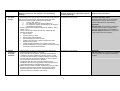
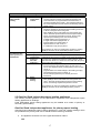
Date
29/10/08
Amendment
The following text deleted from Table 9, Row A, Column 2
“if a combination boiler is installed, the boiler efficiency should be not less than 82% efficiency
(as expressed by its HARP value); OR”
CONTENTS
Section 1.
1.1
1.2
1.3
1.4
Section 2.
2.1
2.2
2.3
2.4
2.5
2.6
2.7
Section 3.
3.1
3.2
3.3
3.4
3.5
Section 4.
4.1
4.2
4.3
PAGE
Introduction.
3
How to use this guide.
Glossary.
The Building Regulations requirements and the guidance
Technical Guidance Document L 2008, Sections 1 and 2
Replacement of primary heating appliances.
4
6
Gas-fired space heating and hot water systems.
8
Scope of guidance.
Gas-fired wet central heating systems.
Gas-fired range cookers with integral central heating boiler.
Gas-fired warm air heating.
Gas-fired fixed independent space heating appliances.
Gas-fired fixed decorative fuel-effect fires.
Gas-fire for secondary-space heating provided as part
of a combined fire and back boiler unit.
8
8
14
15
17
19
Oil-fired wet central heating systems.
21
Scope of guidance.
Oil-fired wet central heating systems.
Oil-fired range cookers with integral central heating boilers.
Continually burning oil-fired vaporising appliances providing
secondary heating or hot water.
Oil-fired fixed independent space heating appliances.
21
21
27
28
29
Electrical heating systems.
30
Scope of guidance.
Electric boilers serving central heating systems in new and
existing dwellings.
Electric heating systems (other than central heating
using electric boilers).
30
1
7
7
19
30
35
Section 5.
5.1
5.2
5.3
5.4
Section 6.
6.1
6.2
Section 7.
7.1
Section 8.
8.1
Section 9.
9.1
Section 10.
Solid-fuel heating systems.
38
Scope of guidance.
Solid-fuel appliances for primary heating.
Central heating systems using certain types of
solid-fuel appliances.
Solid-fuel appliances for secondary heating.
38
38
Community heating systems.
48
Scope of guidance.
Definition of community heating (CH).
48
48
Under floor heating systems.
57
Scope of guidance.
57
Heat pump systems.
60
Scope of guidance.
60
Solar water heating.
64
Scope of guidance.
64
Individual domestic (micro) combined heat and power.
70
40
46
Appendix A Guide to the Condensing Boiler Installation Assessment Procedure for Existing
Dwellings
2
Section 1 Introduction
Part L of the Building Regulations is concerned with the conservation of fuel and energy in
dwellings. Part L for dwellings, is supported by a Technical Guidance Document (TGD) L
Dwellings 2008 which gives guidance on how to satisfy the energy performance provisions of the
Building Regulations for new and existing dwellings.
The TGD quotes the regulatory requirements where relevant for the sake of completeness. These
provisions are distinguished in the text by a grey background. In cases of doubt, however, it may
be necessary to refer directly to the Building Regulations as amended.
The TGD was published in 2008 in support of the amendments to the Building Regulations,
Statutory Instruments No. 854 of 2007. The amendment came into force on 1 July 2008.
Building Regulations 2008 TGD L -Dwellings is more strategic in nature than previous versions
and relies on support documents to provide detailed information on the minimum provisions
necessary to comply with the requirements of the Regulations.
This guide covers conventional means of providing primary and secondary space heating and
domestic hot water for dwellings in Ireland. This guide is the supporting document referred to in
Building Regulations 2008 TGD L Dwellings Par 1.4.1 as a source of guidance on the means of
complying with the requirements of the Building Regulations for space heating systems and hot
water systems. The guide was prepared in consultation with relevant industry bodies.
The co-operation of the UK authorities (Department of Communities and Local Government) is
gratefully acknowledged in allowing the use of the information in its publication “Domestic Heating
Compliance Guide” for official use in Ireland.
For new dwelling requirements in Part L of the Building Regulations 2008, guidance is provided
on the design limits for building services systems referred to in Section 1 of Building Regulations
2008 TGD L- Dwellings. For existing dwellings, guidance is provided on reasonable provision for
the installation or replacement of controlled services as referred to in Section 2 of Building
Regulations 2008 TGD L-Dwellings
Installation of a condensing boiler is deemed not practicable where a prior contractual
commitment in relation to the installation of a boiler was entered into prior to 31st March 2008.
This supporting document identifies standards of provision that meet the guidance for systems in
new build and in those in existing buildings when work is being undertaken. The levels of
performance for new and existing dwellings differ only where practical constraints arise in existing
dwellings while it is recognized that the guide covers a range of frequently occurring situations but
alternative means of achieving compliance may be possible. The status of alternative provisions
is explained in the ‘The Guidance’ section at the front of the Technical Guidance Documents.
This guide also references publications which include information on good practice for design and
installation over and above the minimum regulatory provision.
3
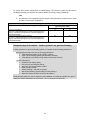
1.1 How to use this guide
This guide covers compliance with the requirements of the Building Regulations 2008, Part L for
conventional space heating systems and hot water service systems in dwellings.
The guide comprises four self-contained fuel-based sections, and five specialist technologyspecific sections. Each fuel-based section addresses all the requirements applicable to primary
and secondary space heating and hot water service technologies for the particular fuel. The
specialist technology-specific sections provide further guidance on the minimum provisions for
particular specialised space heating and hot water service technologies. The structure of the
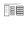
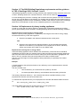
guide is illustrated in Figure 1 and is as follows:
Fuel-based sections:
• Section 2 Gas-fired primary and secondary space heating and hot water service
• Section 3 Oil-fired primary and secondary space heating and hot water service
• Section 4 Electric primary and secondary space heating and hot water service
• Section 5 Solid-fuel primary and secondary space heating and hot water service
Specialist technology-specific sections:
• Section 6 Community heating
• Section 7 Underfloor heating
• Section 8 Heat pumps
• Section 9 Solar water heating
• Section 10 Micro-CHP (Combined Heat and Power)
For any particular application, the relevant fuel-based section and/or specialist technologyspecific section must be read in conjunction with all elements of this introduction section:
• 1. Introduction
• 1.1 How to use this guide
• 1.2 Glossary
• 1.3 The Building Regulations 2008 requirements and the guidance in Technical Guidance
Document L – Dwellings 2008
• 1.4 Replacement of primary heating appliances
For each type of space heating or hot water service system, guidance on the minimum provisions
needed to comply with Part L is supported by commentaries. They are in italic font with a shaded
background and are labeled ‘Supplementary information’. They are useful when interpreting the
minimum provisions and, in some cases, provide links to best practice guidance. They do not
specify minimum provisions.
4
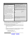
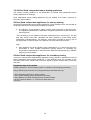
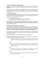
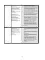
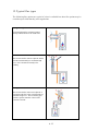
Figure 1 How to use Heating and Domestic Hot Water Systems for
dwellings-Achieving Compliance with Part L 2008
Section 1
Introduction
Section 1.1
How to use the guide
Section 6
Community heating systems
Pages 48 - 56
Section 2
Gas systems
Pages 8 - 20
Section 7
Underfloor heating systems
Pages 57 - 59
Section 1.2
Glossary
Section 1.3
Requirements of
Technical Guidance
Document L
Section 1.4
Replacement of
primary heating
appliances
Section 3
Oil systems
Pages 21 - 29
Section 8
Heat pump systems
Pages 60 - 63
Section 4
Electric systems
Pages 30 - 37
Section 9
Solar hot water systems
Pages 64 - 69
Section 5
Solid-fuel systems
Pages 38 - 47
Section 10
Micro-CHP systems
Page 70
5
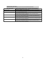
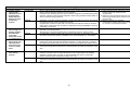
Section 1.2 Glossary
Technical Guidance Document L (TGD L)
Section 1 of TGD L
Dwellings 2008 gives
guidance on how to satisfy the Building
Regulations energy efficiency requirements when
building new dwellings. Effective from 1st July
2008.
Section 2 of TGD L Dwellings 2008 gives
guidance on how to satisfy the Building
Regulations energy efficiency requirements when
carrying out work in existing dwellings. Effective
from 1st July 2008.
The Building Regulations
S.I. No. 497 of 1997 as amended by the Building
Regulations (Part L Amendment) Regulations (S.I.
No. 259 of 2008) ensure the health, safety, welfare
and convenience of people in and around
buildings and reasonable provision for the
conservation of fuel and power and access to and
use of buildings by providing functional
requirements for building design and construction.
Minimum provision
In this document ‘minimum provision’ refers to the
provisions needed to demonstrate compliance of
space heating and hot water service systems
installed in dwellings with the Building Regulations
2008 energy efficiency requirements.
Supplementary information
The commentaries labeled ‘Supplementary
information’ may be useful when interpreting the
minimum provisions and, in some cases, provide
links to best practice guidance.
DEAP
An acronym for Dwellings Environmental
Assessment Procedure, which is the national
methodology for calculating the energy rating of
dwellings
6
Section 1.3 The 2008 Building Regulations requirements and the guidance
in TGD L Dwellings 2008, Sections 1 and 2
The Building Regulations relevant to energy efficiency are repeated for easy reference at the front
of TGD L Dwellings 2008 in the ‘Guidance Section’, which can be viewed on www.environ.ie.
For new dwellings the provision of heating and hot water services systems has to be considered
as part of the overall design of the building. For heating and hot water services systems works in
existing dwellings provision can be considered in isolation. Both sections of the TGD L Dwellings
2008 refer to this publication as the source of detailed guidance on reasonable provision.
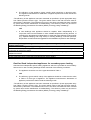
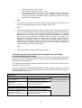
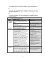
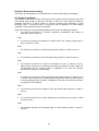
Section 1.4 Replacement of primary heating appliances
In order to comply with the energy efficiency requirements, replacement appliances providing
primary space heating and/or hot water in existing dwellings should meet the following conditions:
Replacement not involving fuel or energy switch
Where the primary heating appliance is replaced by one using the same fuel or energy supply,
the seasonal efficiency of the new equipment:
a. Should be as stated in the relevant fuel-based section of this guide.
AND
b. Should be not worse than the seasonal efficiency of the controlled service being
replaced. If the efficiency of the appliance to be replaced is not known, efficiency
values may be taken from Table 4a or 4b of DEAP 2008.
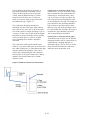
Replacement involving fuel or energy switch
If the new heating appliance uses a different fuel, the efficiency of the new service should be
multiplied by the ratio of the CO2 emission factor of the fuel used in the service being replaced to
that of the fuel used in the new service before making the checks described in paragraph a or b
above. The CO2 emission factors should be taken from Table 8 of DEAP 20081.
The aim is to discourage an existing appliance being replaced by a significantly less carbonefficient one.
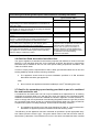
Example
A Liquid Petroleum Gas (LPG) fired boiler of 79% efficiency is to be replaced with an oil boiler
(post 01/04/08).
The new oil boiler must:
i.
have an efficiency of not less than 86% (Table 9), and also
ii.
its carbon equivalent efficiency must be better than the existing LPG boiler.
The existing LPG boiler efficiency = 79%; therefore the carbon equivalent efficiency of the
proposed new oil boiler must not be less than 79%.
To calculate the required efficiency for the proposed new oil boiler with DEAP 2008 fuel factors
of:
Oil = 0.272 kg CO2 / kWh, LPG = 0.232 kg CO2 / kWh
The actual HARP approved new oil boiler efficiency must be greater than
79% ÷ (0.232 / 0.272) = 79% / 0.853 = 92.6%
1
The relevant column in Table 8 of DEAP (2008) is the one entitled “Emissions, kg CO2/kWh”
7
Section 2 Gas-fired space heating and hot water systems
This section provides guidance on the specification of gas-fired space heating and hot water
systems in dwellings.
All gas appliances should be installed by a competent person and in accordance with CER
Criteria document "THE REGULATION OF GAS INSTALLERS WITH RESPECT TO SAFETY".
When the Gas Installers Register is put in place , all installers of gas appliances must be a
registered gas installer. The installation should be carried out to the manufacturer’s instructions
and should comply with all other relevant parts of the Building Regulations and, for wet systems,
local authority guidelines.
2.1 Scope of guidance
The guidance in this section applies to systems fuelled by natural gas and liquid petroleum gas
(LPG); any requirements specific to either fuel type are identified.
The following types of gas-fired heating systems are addressed:
• Wet central heating systems.
• Range cookers with integral central heating boilers.
• Warm air heating systems.
• Fixed independent space heating devices.
Where appropriate, it may be necessary to refer to other sections in this guide covering
community heating, underfloor heating, heat pumps, solar water heating and micro-CHP.
2.2 Gas-fired wet central heating systems
This section provides guidance on the specification of gas-fired wet central heating systems for
dwellings that, if followed, will satisfy the energy efficiency requirements of the Building
Regulations 2008.
Terminology and applicability of guidance to different scenarios in new and existing
dwellings
The guidance in this section applies to the following situations:
a. The specification of central heating systems in new dwellings – this situation is referred
to in this section as a new system.
b. The specification of central heating systems in existing dwellings where previously
space heating was not provided by central heating – this situation is also referred to in
this section as a new system
c. The specification of a replacement central heating system and/or component in
existing dwellings where central heating is already installed – this situation is referred to
in this section as a replacement system.
In situations (a) and (b) above, the guidance for compliance of new systems (in new and existing
dwellings) with Part L 2008 is the same.
In situation (c) above, that is for replacement systems in existing dwellings, the guidance for
compliance with Part L 2008 is as for new systems, unless otherwise stated in the relevant
section.
Gas-fired central heating systems which are provided as new systems or replacement systems in
dwellings should meet the following conditions:
a. The boiler should have a minimum efficiency (as defined by its HARP value) as given
in Table 1 (row a).
AND
b. The minimum provisions for system circulation as given in Table 1 (row b) need to be
met.
8
AND
c.
The minimum provisions for hot water storage and labeling of storage vessels as
given in Table 1 (row c) need to be met.
AND
d. The minimum provisions for system preparation and water treatment as given in
Table 1 (row d) should be met.
AND
e. The system should be commissioned in accordance with the minimum provisions
given in Table 1 (row e).
AND
f.
The minimum provisions for boiler interlock, zoning and time control and temperature
control of the heating and hot water service circuits as described in Table 2 should be
met. An acceptable alternative to these is any boiler management system that
delivers the specified zoning, timing and temperature and boiler interlock control
provisions. When gas boilers are installed as part of a replacement system, the
minimum level of system controls should be provided, as described in Table 2, unless
they are already installed and fully operational. If an individual component of the
control system is being replaced in an existing system, for example a room
thermostat, it is not necessary to upgrade the system to meet the minimum
requirements.
AND
g. Pipework should be insulated as described in Table 3.
9
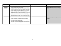
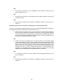
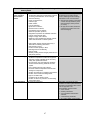
Table 1 Minimum provisions for boiler efficiency, system circulation, hot water storage, system preparation and commissioning of gas-fired central heating
systems in new dwellings (and in existing dwellings where appropriate)
Minimum provision for new systems in dwellings
a. Minimum
acceptable
efficiency
b. System
circulation
a. The boiler efficiency should be not less than 86% (HARP
value).
b. The boiler efficiency for heating boilers that are combined with
range cookers should be as defined in the section of this guide
‘Section 2.3 Gas-fired range cookers with integral central
heating boilers’ of this guide.
a. Systems for space heating and domestic hot water primary
circuits should have fully pumped circulation
b. If the boiler manufacturer’s instructions advise installation of a
bypass, an automatic bypass valve should be provided in
conjunction with any requirements for a minimum pipe length
specified in the manufacturer’s instructions
Minimum provision for replacement systems
in existing dwellings
Replacements not involving a fuel or energy
switch
The seasonal efficiency of the new equipment
should be:
• as defined for new systems; and
• not worse than the seasonal efficiency of
the controlled service being replaced. If the
efficiency of the system or appliance to be
replaced is not known, efficiency values
may be taken from Table 4a or 4b of DEAP
2008
Replacement involving fuel or energy switch
If the new heating system or heat generating
appliance uses a different fuel, the efficiency of
the new service should be multiplied by the ratio
of the CO2 emission factor of the fuel used in the
service being replaced to that used in the new
service. The CO2 emission factors should be
taken from Table 8 of DEAP 2008 – (the relevant
column in Table 8 is titled ‘Emissions, kg
CO2/kWh’)
As defined for new systems. When boilers are
replaced, existing systems with semi-gravity
circulation should be converted to fully pumped
circulation
10
Supplementary information
Guidance on identifying the HARP efficiency
for an appliance
The Heating Appliance Register of Performance
Database is available online (www.SEI.ie/HARP)
and includes regularly updated information on
most available boilers as well as many which are
no longer in production
Appendix 1 gives the approved procedure for
establishing where exceptional circumstances
exist. This follows the criteria set out in the Guide
to the Condensing Boiler Installation Assessment
Procedure for Existing Dwellings
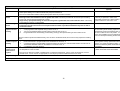
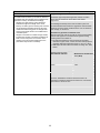
Table 1 (continued)
c. Hot water
storage
d. System
preparation
and water
treatment
Minimum provision for new systems in new and existing
dwellings
Minimum provision for replacement systems
in existing dwellings
Supplementary information
a. Vented copper hot water storage vessels should comply with the
heat loss and heat exchanger requirements of BS1566:2002.
Unvented hot water storage systems products should
i.
meet IS. EN. 12897; or
ii.
be certified by the Irish Agrément Board; or
iii.
be certified by another accredited body as complying
with Building Regulations
b. Standing heat losses should be restricted as defined in TGD-L
section 1.4.4.2.
c. All hot water storage vessels should carry a label with the
following information:
•
type of vessel;
•
nominal capacity in litres;
•
standing heat loss in kWh/day;
•
heat exchanger performance in kW;
•
vented copper hot water cylinders should carry clear
labeling on the product
•
vented cylinders which are not of copper construction
should be labelled as complying with the heat loss and heat
exchanger requirements of BS1566.
As defined for new systems
Insulation of primary stores
Because of the higher than normal storage
temperatures in primary stores it is very
important that these are well insulated
a. Central heating systems should be thoroughly cleaned and
flushed out before installing a new boiler
b. During final filling of the system, a chemical water treatment
formulation should be added to the primary circuit to control
corrosion and the formation of scale and sludge. Reasonable
provision would be to follow the guidance on how to prepare
and commission systems given in BS7593
c. Installers should also refer to the boiler manufacturer’s
installation instructions for appropriate treatment products and
special requirements for individual boiler models
d. Where the mains water hardness exceeds 200 parts per million,
provisions should be made to treat the feed water to water
heaters and the hot water circuit of combination boilers to
reduce the rate of accumulation of lime scale
As defined for new systems
Standards
BS 1566: 2002 Copper indirect cylinders for
domestic purposes. Open vented copper
cylinders. Requirements and test methods
BS 7206:1990 Specification for unvented hot
water storage units and packages
11
Standards
BS 7593:1992 Code of practice for treatment of
water in domestic hot water central heating
systems
Table 1 (continued)
e.
Commissioning
Minimum provision for new systems in new and existing
dwellings
a. On completion of the installation of a boiler/or a hot water
storage system, together with associated equipment such as
pipework, pumps and controls, the equipment should be
commissioned in accordance with the manufacturer’s
instructions. These instructions will be specific to the particular
boiler and/or hot water storage system
b. The installer should give a full explanation of the system and its
operation to the user, including the manufacturer’s user manual
where provided.
Minimum provision for replacement systems
in existing dwellings
As defined for new systems
12
Supplementary information
Table 2 Minimum provisions for control of gas-fired central heating systems in new dwellings*
System Control
Boiler interlock
Space heating
zones
Water heating
zones
Time control of
space and water
heating
Recommended provision for new systems
• Boiler-based systems should have boiler control interlock in which controls are wired so that when there is no demand for either
space heating or hot water the boiler and pump are switched off
• The use of Thermostatic Radiator Valves (TRVs) alone does not provide an interlock.
• Dwellings with a total usable floor area of greater than 100m2 should be provided with at least two space heating zones each
having separate temperature controls
• Single-storey open-plan dwellings in which the living area is greater than 70% of the total floor area – sub-zoning of
temperature control is not appropriate.
• All Dwellings should have a separate hot water zone in addition to space heating zones.
• A separate hot water service zone is not required if the hot water is produced instantaneously such as with a
combination boiler.
Time control of space and water heating should be provided by:
i. A full programmer with separate timing to each circuit or
ii. Two or more separate timers providing timing control to each circuit; or
iii. Programmable room thermostat(s) to the heating circuit(s), with separate timing of the hot water circuit.
Where hot water is produced instantaneously, such as with a combination boiler, time control is only required for heating zones.
Temperature
control of space
heating
Separate temperature control of zones within the dwelling, should be provided, using:
i. Room thermostats or programmable room thermostats in all zones; or
ii. a room thermostat or programmable room thermostat in the main zone and individual radiator controls such as Thermostatic
Radiator Valves on all radiators in the other zones; or
iii. a combination of (i) and (ii) above.
Temperature
control of hot
water service
system
• Domestic hot water systems should be provided with a cylinder thermostat and a zone valve or three-port valve to control the
temperature of the hot water.
• Where more than one hot water circuit exists. Each should have separate temperature controls.
Recommended provision for existing
systems
As defined for new systems
As defined for new systems except
where the boiler only is replaced, in
which case reasonable provision for a
space heating system would be to
control one zone
As defined for new systems
As defined for new systems except
where only the hot water cylinder is
being replaced in a replacement system
and separate time control for the hot
water circuit is not present. In this case
it is acceptable to have a single timing
control for both space heating and hot
water.
For replacement systems where only
the hot water cylinder is being replaced
and where hot water is on a gravity
circulation system, a thermomechanical cylinder thermostat should
be installed.
A thermo-mechanical cylinder
thermostat should be installed.
• The use of non-electric hot water controllers does not meet this requirement. Also in some circumstances, such as thermal
stores, a zone valve is not appropriate; a second pump could be substituted as the zone valve.
Supplementary information
*An acceptable alternative to these controls is any boiler management control system that meets the specified zoning, and temperature and boiler interlock control requirements.
13
Table 3 Minimum provisions for insulation of pipes serving gas-fired central heating systems
Minimum provision
In new systems pipes should be insulated as follows
(in line with the maximum permissible heat loss
indicated in the Supplementary Information column),
and labelled accordingly:
• Primary circulation pipes for heating and hot water
circuits should be insulated wherever they pass
outside the heated living space or through voids
which communicate with and are ventilated from
unheated spaces
• Pipes and ducts which are incorporated into wall,
floor or roof construction should be insulated.
• Primary circulation pipes for hot water service
circuits should be insulated throughout their
length, subject only to practical constraints
imposed by the need to penetrate joists and other
structural elements • All pipes connected to hot
water storage vessels, including the vent pipe,
should be insulated for at least 1m from their
points of connection to the cylinder (or they should
be insulated up to the point where they become
concealed)
• If secondary circulation is used, all pipes kept hot
by that circulation should be insulated
For replacement systems, whenever a boiler or hot
water storage vessel is replaced in an existing
system, any pipes (in the situations above) that are
exposed as part of the work or are otherwise
accessible should be insulated as recommended in
this guide (in line with the maximum permissible heat
loss indicated in the Supplementary Information
column), and labelled accordingly – or to some lesser
standard where practical constraints dictate.
Supplementary information
Insulation for pipework in unheated areas
Extra provision may need to be made to protect central heating
and hot water pipework in unheated areas against freezing.
Further guidance is available in:
• BS 5422:2001 Method for specifying thermal insulating
materials for pipes, tanks, vessels, ductwork and equipment
operating within the temperature range of –40°C to +700°C
• BRE Report No 262 Thermal insulation: avoiding risks, 2002
edition
Where insulation is labelled as complying with the Heating and
Domestic Hot Water Systems for dwellings-Achieving
Compliance with Part L it must not exceed the following heat loss
levels:
Pipe diameter (OD) mm
Maximum permissible heat
loss* (W/m)
8mm
7.06
10mm
7.23
12mm
7.35
15mm
7.89
22mm
9.12
28mm
10.07
35mm
11.08
42mm
12.19
54mm
14.12
*In assessing the thickness of insulation required to meet the
provision, standardised conditions should be used in all
compliance calculations based in this instance on a horizontal
pipe at 60ºC in still air at 15ºC
2.3 Gas-fired range cookers with integral central heating boiler
This section provides guidance on the specification of gas-fired range cookers with integral
central heating boilers for space heating and hot water in dwellings.
Gas-fired range cookers with an integral central heating boiler which are provided in new or
existing dwellings should meet the following conditions:
a. The appliance should have two independently controlled burners (one for the cooking
function and one for the boiler) and the boiler should have a Seasonal Efficiency
(HARP2) value in excess of 75%.
AND
b. Information about appliance performance should be included in the commissioning
information given at completion. The manufacturer’s declaration of appliance
performance and HARP value should include the following words:
”
• Seasonal efficiency (HARP) = xx%
• Case heat emission value = yy kW
• Heat transfer to water at full load = zz kW
2
Seasonal Efficiencies for appliances can be found in HARP database and in the national methodology
for Building Energy Rating (DEAP) at www.sei.ie/HARP and www.sei.ie/DEAP
14
The values are used in the Dwelling Energy Assessment Procedure (DEAP) for the
energy rating of dwellings. The test data from which they have been calculated has
been certified by {insert name and/or identification of Notified body}.”
AND
c.
The minimum provisions for gas-fired central heating systems with respect to the
integral central heating boilers as given in Table 1 (rows B–E);
AND
d. The minimum provisions for boiler interlock, zoning and time control and temperature
control of the heating and hot water circuits with respect to the integral central heating
boilers as given in Table 2 for gas-fired central heating systems. An acceptable
alternative to these is any boiler management system that delivers the specified
zoning, timing and temperature provisions. When gas boilers are installed as a
replacement for existing boilers, the minimum level of system controls should be
provided, as described in Table 2, unless they are already installed and fully
operational. If an individual component of the control system is being replaced in an
existing system, for example a room thermostat, it is not necessary to upgrade the
system to meet the minimum requirements;
AND
e. Pipework should be insulated as described in Table 3.
2.4 Gas-fired warm air heating
This section provides guidance on the specification of gas-fired warm air heating systems for
dwellings.
Terminology and applicability of guidance to different scenarios in new and existing
dwellings
The guidance in this section applies to the following situations:
a. The specification of gas-fired warm air heating systems in new dwellings – this
situation is referred to in this section as a new system.
b. The specification of gas-fired warm air heating systems in existing dwellings where
previously space heating was not provided by a warm air system – this situation is
also referred to in this section as a new system;
c. The specification of a replacement warm air heating system and/or component in
existing dwellings where warm air heating is already installed – this situation is
referred to in this section as a replacement system.
Gas-fired warm air heating which is provided as a new system or replacement system in new
or existing dwellings should meet the following conditions:
a. The minimum provisions for efficiency and installation set out in Table 4;
AND
b. The minimum provisions for system control set out in Table 5.
15
Table 4 Minimum provisions for efficiency and installation of gas-fired warm air heating
systems
Efficiency
Minimum provision
Supplementary information
a.
Gas-fired warm air units should meet
the requirements, as appropriate to the
design of the appliance, of:
• IS EN 778:1998 or
• IS EN 1319:1999
b.
If a gas-fired circulator is incorporated in
the warm air unit to provide domestic
hot water, it should be able to deliver
full and part load efficiency at least
equal to that prescribed by IS EN
483:1999/A4:2007
Standards
IS EN 778:1998 Domestic gas-fired
forced convection air heaters for space
heating not exceeding a net heat input
of 70kW, without a fan to assist
transportation of combustion air and/or
combustion products
c.
The manufacturer’s declaration of
appliance performance and efficiency
value should include the following
words:
IS EN 1319:1999 Domestic gas-fired
forced convection air heaters for space
heating, with fan-assisted burners not
exceeding a net heat input of 70kW
IS EN 483:2000 Gas-fired central
heating boilers. Type C boilers of
nominal heat input not exceeding 70kW
Combined warm air unit and circulator
This product has been assessed against the
test methods set out in IS EN 778:1998* or
IS EN 1319: 1999* {* as appropriate} and IS
EN 483* and certified as meeting those
minimum requirements by {insert name
and/or identification of Notified Body}
Warm air unit alone
This product has been assessed against the
test method set out in IS EN 778: 1998* or
IS EN 1319; 1999* {*deleted as appropriate}
and certified as meeting the minimum
requirements by {insert name
and/or identification of Notified Body}
Installation
a.
b.
The system should be installed in
accordance with BS 5864:2004
Ductwork that is newly installed or
replaced should be insulated in
accordance with the recommendations
of BS 5422:2001
BS 5864:2004 Installation and
maintenance of gas-fired ducted air
heaters of rated input not exceeding
70kW net (second and third family
gases). Specification
BS 5422:2001 Method for specifying
thermal insulating materials for pipes,
tanks, vessels, ductwork and
equipment operating within the
temperature range of –40°C to +700°C
16
Table 5 Minimum provision for system controls for gas-fired warm air heating
System
Warm air systems
without water
heating
Combined warm air
and domestic hot
water systems for
installations
Minimum provision
i. Time and
Time and temperature control should be provided by either:
temperature
i. controls external to heater: time switch/programmer and
control
room thermostat, or programmable room thermostat; or
ii. controls integrated in the heater – time-switch/programmer
and room temperature sensor linked to heater firing and fan
speed control.
ii. Zoning
• New dwellings with a total usable floor area up to 100m2
should be divided into at least two space heating zones one
of which is assigned to the living area
• New dwellings with a total usable floor area greater than
2
100m should be provided with at least two space heating
zones, each having temperature controls. Timing of the
separate space heating zones can be achieved by:
i. multiple heating zone programmers; or
ii. a single multi-channel programmer; or
iii. programmable room thermostats; or
iv. separate timers to each circuit; or
v. a combination of (iii) and (iv) above.
The provisions for zoning for replacement systems in existing
dwellings should be as for new dwellings where practical
iii. Independent time control of both the heating and hot water circuits
iv.
Pumped primary circulation to the hot water cylinder
v.
Independent
control of
hot water
production
Time control
vi.
vii.
Space
heating
zoning
Independent control of the hot water circuit should be achieved
by means of a cylinder thermostat and a timing device, wired
such that when there is no demand for hot water both the pump
and circulator are switched off .
Time control should be provided by use of:
• a full programmer with separate timing to each circuit; or
• two or more separate timers providing timing control to each
circuit; or
• programmable room thermostat(s) to the heating circuit(s),
with separate timing of the hot water; or
• a time switch/programmer (two channel) and room
thermostat.
• New dwellings with a total usable floor area greater than
100m2 should be provided with at least two space heating
zones, each having separate temperature controls.
The provisions for zoning for replacement systems in existing
dwellings should be as for new dwellings where practical
2.5 Gas-fired fixed independent space heating appliances
This section provides guidance on the specification of gas-fired fixed independent space
heating appliances for dwellings.
Fixed independent space heating appliances may be installed as a means of primary or
secondary space heating.
Gas-fired fixed independent appliances for primary-space heating
Gas-fired fixed independent space heating appliances in new and existing dwellings which
are provided as the primary heat source should meet the following conditions:
a. The appliance should be one of the types described in Table 6
AND
17
b. The efficiency of the appliance (gross calorific value) should be no less than 58%.
The appliance manufacturer’s declaration of appliance performance shall include the
following words:
“The efficiency of this appliance has been measured as specified in {insert appropriate entry
from Table 6} and the result is [x]%. The gross calorific value of the fuel has been used for
this efficiency calculation. The test data from which it has been calculated has been certified
by {insert name and/or identification of Notified Body}. The efficiency value may be used in
the Dwelling Energy Assessment Procedure (DEAP) for energy rating of dwellings.”
AND
c.
In new dwellings each appliance should be capable, either independently or in
conjunction with room thermostats or other suitable temperature sensing devices, of
controlling the temperatures independently in areas that have different heating needs
(e.g. separate sleeping and living areas). In existing dwellings, wherever practical,
temperature controls should be upgraded to the standards required for new dwellings.
Table 6 Acceptable appliance types for fixed natural gas and LPG gas-fired space heaters for use as a
primary heat source
National Standard designation (appliance type)
IS EN 1266:2002 Independent gas-fired convection heaters incorporating a fan to assist transportation of
combustion air and/or flue gases
BS 7977-1:2002 Specification for safety and rational use of energy of domestic gas appliances.
Radiant/convectors
IS EN 613:2001 Independent gas-fired convection heaters
IS EN 13278:2003 Open fronted gas-fired independent space heaters
Gas-fired fixed independent appliances for secondary-space heating
Gas-fired fixed independent space heating appliances which are provided as the secondary
heat source in new or existing dwellings should meet both of the following conditions:
a. The appliance should be one of the types described in Table 7.
AND
b. The efficiency (gross calorific value) of the appliance should be no less than the value
in Table 7 for that type of appliance. The appliance manufacturer’s declaration of
appliance performance shall include the following words:
“The efficiency of this appliance has been measured as specified in {insert appropriate entry
from Table 7} and the result is [x]%. The gross calorific value of the fuel has been used for
this efficiency calculation. The test data from which it has been calculated has been certified
by {insert name and/or identification of Notified Body}. The efficiency value may be used in
the Dwelling Energy Assessment Procedure (DEAP) for energy rating of dwellings.”
18
Table 7 Acceptable appliance types and minimum appliance efficiencies for independent
fixed natural gas and LPG gas-fired space heaters used as a secondary heat source
National Standard designation (appliance type)
IS EN 1266:2002 Independent gas-fired convection heaters
incorporating a fan to assist transportation of combustion air
and/or flue gases
(All types except inset live fuel effect) BS 7977-1:2002
Specification for safety and rational use of energy of domestic
gas appliances. Radiant/convectors
IS EN 613:2003 Independent gas-fired convection heaters
IS EN 13278:2003 Open fronted gas-fired independent space
heaters
(Inset live fuel effect)
BS 7977-1:2002 Specification for safety and rational use of
energy of domestic gas appliances. Radiant/convectors
(Flue-less)
IS EN 14829:2007 Independent gas fired flueless space
heaters for nominal heat input not exceeding 6kW
(Flue-less)
IS EN 449:2002 Specification for dedicated liquefied petroleum
gas appliances. Domestic flueless space heaters (including
diffusive catalytic combustion heaters
Minimum efficiency %
(gross calorific value)
Gas
LPG
72
73
63
64
58
45
60
46
40
41
Thermal efficiency requirements for this type
of appliance are not specified as all the heat
produced by the combustion process is
released into the space to be heated. In
DEAP the efficiency of these appliances is
classed as 90% and an adjustment is made
for ventilation in the space heating
requirement calculation
2.6 Gas-fired fixed decorative fuel-effect fires
This type of appliance is intended for decorative purposes and therefore a minimum thermal
efficiency is not specified. Note that, for the purposes of DEAP, the efficiency of decorative
fuel-effect fires is classed as 20% for use in the space heating requirement calculation; see
Table 4a of DEAP 2008.
In order to comply with the requirements of Part L 2008, gas-fired decorative fires in new and
existing dwellings should meet the following conditions:
a. The appliance should meet the product standards specified in IS EN 509:2000
Decorative fuel-effect gas appliances.
AND
b. No more than one appliance should be installed per 100m2 of dwelling floor area.
2.7 Gas-fire for secondary-space heating provided as part of a combined
fire and back boiler unit
A combined fire and back boiler unit can only be installed as a replacement for an existing
combined fire and back boiler unit, and then only when the criteria of the Condensing Boiler
Installation Assessment procedure are satisfied as outlined in Appendix A of this document. In
order to comply with the requirements of the Building Regulations 2008, the gas fire provided
as a secondary heat source as part of a combined fire and back boiler unit, when provided as
a replacement system in existing dwellings, should meet the following conditions:
a. The appliance should be one of the types described in Table 8. The manufacturer’s
declaration of appliance performance shall include the following words:
“The efficiency of this appliance has been measured as specified in {insert appropriate entry
from Table 8} and the result is [x]%. The gross calorific value of the fuel has been used for
this efficiency calculation. The test data from which it has been calculated has been certified
19
by {insert name and/or identification of Notified Body}. The efficiency value may be used in
the Dwelling Energy Assessment Procedure (DEAP) for energy rating of dwellings.”
AND
b. The efficiency of the appliance (gross calorific value) should be no less than the value
in Table 8 for that type of appliance.
Table 8 Minimum appliance efficiencies for gas fires used with back boilers
National Standard designation (appliance type)
(Inset live fuel effect)
BS 7977-2:2003 Specification for safety and rational use of
energy of domestic gas appliances. Combined appliances.
Gas fire/back boiler
((All types except inset live fuel effect)
BS 7977-2:2003 Specification for safety and rational use of
energy of domestic gas appliances. Combined appliances.
Gas fire/back boiler
Minimum efficiency %
(gross calorific value)
Gas
LPG
40
41
63
64
.
Supplementary information – further guidance on gas-fired heating
Further guidance on gas-fired heating systems is available in the following publications:
Energy Efficiency Best Practice in Housing publications:
• CE30 Domestic heating by gas: boiler systems;
• CE51 Central heating system specifications (CHeSS);
• CE54 Whole house boiler sizing method for houses and flats.
CORGI publications:
• Essential Gas Safety (GID1);
• Gas Cookers and Ranges (GID2);
• Gas Fires and Space Heaters (GID3);
• Water Heaters (GID5);
• Central Heating – wet and dry (GID7);
• Wet Central Heating System Design Guide (WCH1);
• Warm Air Heating System Design Guide (WAH1).
Requirements relating to various aspects of the installation of condensing boilers are given in
IS EN 813 ,British Standards, BS 5440 Parts 1 and 2, BS 5449 and BS 6798.
20
Section 3 Oil-fired space heating and hot water systems
This section provides guidance on the specification of oil-fired space heating and hot water
systems in dwellings to meet the 2008 Building Regulations energy efficiency requirements.
All oil appliances must be installed by a suitably qualified person and the installation should
be carried out in accordance with the manufacturer’s instructions and comply with all other
relevant parts of the Building Regulations and, for wet systems, Local Authority guidelines.
3.1 Scope of guidance
The guidance in this section applies to systems fuelled by oil. The following types of oil-fired
heating systems are addressed:
•
•
•
•
Wet central heating systems.
Range cookers with integral central heating boilers.
Vaporising appliances providing secondary heating or hot water.
Fixed independent space heating devices.
Where appropriate, it may be necessary to refer to the sections in this guide covering
community heating, underfloor heating, heat pumps, solar water heating and micro-CHP.
3.2 Oil-fired wet central heating systems
This section provides guidance on the specification of oil-fired wet central heating systems for
dwellings that, if followed, will satisfy the energy efficiency requirements of the 2008 Building
Regulations.
Terminology and applicability of guidance to different scenarios in new and existing
dwellings
The guidance in this section applies to the following situations:
a. The specification of central heating systems in new dwellings – this situation is
referred to in this section as a new system.
b. The specification of central heating systems in existing dwellings where previously
space heating was not provided by central heating – this situation is also referred to
in this section as a new system.
c. The specification of a replacement central heating system and/or component in
existing dwellings where central heating is already installed – this situation is referred
to in this section as a replacement system.
In situations (a) and (b) above the guidance for compliance of new systems (in new and
existing dwellings) with Part L is the same.
In situation (c) above, that is for replacement systems in existing dwellings, in most cases the
guidance for compliance with Part L is as for new systems, unless otherwise stated in the
relevant section.
In order to comply with the requirements of Part L, oil-fired central heating systems which are
provided as new systems or replacement systems in dwellings should meet all of the following
conditions:
a. The boiler should have a minimum efficiency (as defined by its HARP value) as
given in Table 9 (row a),
AND
b. The minimum provisions for system circulation as given in Table 9 (row b),
AND
21
c.
The minimum provisions for hot water storage and labelling of storage vessels as
given in Table 9 (row c).
AND
d. The minimum provisions for system preparation and water treatment as given in
Table 1 (row d).
AND
e. The system should be commissioned in accordance with the minimum provisions
given in Table 9 (row e).
AND
f.
The minimum provisions for boiler interlock, zoning and time control and
temperature control of the heating and hot water service circuits as described in
Table 10. An acceptable alternative to these is any boiler management system
that delivers the specified zoning, timing and temperature and boiler interlock
control provisions. When oil boilers are installed as part of a replacement system,
the minimum level of system controls should be provided, as described in Table
10, unless they are already installed and fully operational. If an individual
component of the control system is being replaced in an existing system, for
example a room thermostat, it is not necessary to upgrade the system to meet
the minimum requirements.
AND
g. Pipework should be insulated as described in Table 11.
22
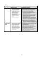
Table 9 Minimum provisions for boiler efficiency, system circulation, hot water storage, system preparation and commissioning of oil-fired central heating
systems in new dwellings (and in existing dwellings where appropriate).
a. Minimum
acceptable
efficiency
Minimum provision for new systems in new and existing
dwellings
a. The boiler efficiency should be not less than 86% (HARP
value)
For range cooker boilers
a. The boiler efficiency for heating boilers that are combined with
range cookers should be as defined in the section of this guide
‘Section 3.3 Oil-fired range cookers with integral central
heating boilers’
b. System
circulation
a.
b.
Systems for space heating and domestic hot water primary
circuits should have fully pumped circulation
If the boiler manufacturer’s instructions advise installation of a
bypass, an automatic bypass valve should be provided in
conjunction with any requirements for a minimum pipe length
specified in the manufacturer’s instructions
Minimum provision for replacement systems
in existing dwellings
Replacements not involving a fuel or energy
switch
The seasonal efficiency of the new equipment
should be:
• as defined for new systems; and
• not worse than the seasonal efficiency of
the controlled service being replaced. If the
efficiency of the system or appliance to be
replaced is not known, efficiency values
may be taken from Table 4a or 4b of DEAP
2008
Replacement involving fuel or energy switch
If the new heating system or heat generating
appliance uses a different fuel, the efficiency of
the new service should be multiplied by the ratio
of the CO2 emission factor of the fuel used in the
service being replaced to that used in the new
service. The CO2 emission factors should be
taken from Table 8 of DEAP 2008 – (the relevant
column in Table 8 of DEAP (2008) is that titled
‘Emissions, kg CO2/kWh’)
As defined for new systems. When boilers are
replaced, existing systems with semi-gravity
circulation should be converted to fully pumped
circulation
23
Supplementary information
Guidance on identifying the HARP efficiency
for an appliance
The Heating Appliance Register of Performance
Database is available online (www.SEI.ie/HARP)
and includes regularly updated information on
most available boilers as well as many which are
no longer in production
Appendix 1 of the Heating and Domestic Hot
Water Systems-Achieving Compliance with
Part L gives the approved procedure for
establishing where exceptional circumstances
exist. This follows the criteria set out in the Guide
to the Condensing Boiler Installation Assessment
Procedure for Existing Dwellings
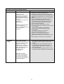
Table 9 (continued)
c. Hot water
storage
Minimum provision for new systems in new and existing
dwellings
a. Vented copper hot water storage vessels should comply with
the heat loss and heat exchanger requirements of
BS1566:2002.
b. Unvented hot water storage systems products should:
i. comply with IS. EN. 12897; or
ii. be certified by the Irish Agrément Board; or
iii. be certified by another accredited body as complying with
Building Regulations
c. Standing heat losses should be restricted as defined in TGD-L
section 1.4.4.2.
d. All hot water storage vessels should carry a label with the
following information:
•
type of vessel;
•
nominal capacity in litres;
•
standing heat loss in kWh/day;
•
heat exchanger performance in kW;
•
vented copper hot water cylinders should carry clear
labeling on the product
•
vented cylinders which are not of copper construction
should be labelled as complying with the heat loss and heat
exchanger requirements of BS1566.
Minimum provision for replacement systems
in existing dwellings
As defined for new systems
Supplementary information
Insulation of primary stores
Because of the higher than normal storage
temperatures in primary stores it is very
important that these are well insulated
Standards
BS 1566: 2002 Copper indirect cylinders for
domestic purposes. Open vented copper
cylinders. Requirements and test methods
BS 7206:1990 Specification for unvented hot
water storage units and packages
24
Table 9 (continued)
d. System
preparation
and water
treatment
e.
Commissioning
Minimum provision for new systems in new and existing
dwellings
a. Central heating systems should be thoroughly cleaned and
flushed out before installing a new boiler
b. During final filling of the system, a chemical water treatment
formulation should be added to the primary circuit to control
corrosion and the formation of scale and sludge. Reasonable
provision would be to follow the guidance on how to prepare
and commission systems given in BS7593
c. Installers should also refer to the boiler manufacturer’s
installation instructions for appropriate treatment products and
special requirements for individual boiler models
d. Where the mains water hardness exceeds 200 parts per
million, provisions should be made to treat the feed water to
water heaters and the hot water circuit of combination boilers
to reduce the rate of accumulation of lime scale
a. On completion of the installation of a boiler/or a hot water
storage system, together with associated equipment such as
pipework, pumps and controls, the equipment should be
commissioned in accordance with the manufacturer’s
instructions. These instructions will be specific to the particular
boiler and/or hot water storage system
b. The installer should give a full explanation of the system and
its operation to the user, including the manufacturer’s user
manual where provided.
Minimum provision for replacement systems
in existing dwellings
As defined for new systems
Supplementary information
As defined for new systems
Site commissioning of oil-fired appliances should
always be carried out as it is critical for efficient
operation.
25
Standards
BS 7593:1992 Code of practice for treatment of
water in domestic hot water central heating
systems
Table 10 Minimum provisions for control of oil-fired central heating systems in new dwellings*
System Control
Recommended provision for new systems
Boiler interlock
• Boiler-based systems should have boiler control interlock in which controls are wired so that when there is no demand for
either space heating or hot water the boiler and pump are switched off
• The use of Thermostatic Radiator Valves (TRVs) alone does not provide an interlock.
Space heating
zones
Water heating
zones
Time control of
space and water
heating
Temperature
control of space
heating
Temperature
control of hot
water service
system
• Dwellings with a total usable floor area of greater than 100m2 should be provided with at least two space heating
zones each having separate temperature controls
• Single-storey open-plan dwellings in which the living area is greater than 70% of the total floor area – sub-zoning
of temperature control is not appropriate.
• All Dwellings should have a separate hot water zone in addition to space heating zones.
• A separate hot water service zone is not required if the hot water is produced instantaneously such as with a
combination boiler.
Time control of space and water heating should be provided by:
i.
A full programmer with separate timing to each circuit; or
ii.
Two or more separate timers providing timing control to each circuit; or
iii.
Programmable room thermostat(s) to the heating circuit(s), with separate timing of the hot water circuit.
Where hot water is produced instantaneously, such as with a combination boiler, time control is only required for heating
zones.
Separate temperature control of zones within the dwelling, should be provided, using:
i.
Room thermostats or programmable room thermostats in all zones; or
ii.
a room thermostat or programmable room thermostat in the main zone and individual radiator controls such as
Thermostatic Radiator Valves on all radiators in the other zones; or
iii.
a combination of (i) and (ii) above.
• Domestic hot water systems should be provided with a cylinder thermostat and a zone valve or three-port valve to control
the temperature of the hot water.
Recommended provision for existing
systems
As defined for new systems
As defined for new systems except where the
boiler only is replaced, in which case
reasonable provision for a space heating
system would be to control one zone
As defined for new systems
As defined for new systems except where only
the hot water cylinder is being replaced in a
replacement system and separate time control
for the hot water circuit is not present. In this
case it is acceptable to have a single timing
control for both space heating and hot water.
For replacement systems where only the hot
water cylinder is being replaced and where hot
water is on a gravity circulation system, a
thermo-mechanical cylinder thermostat should
be installed.
As a minimum provision a thermo-mechanical
cylinder thermostat should be installed.
• The use of non-electric hot water controllers does not meet this requirement. Also in some circumstances, such as
thermal stores, a zone valve in not appropriate; a second pump could be substituted as the zone valve.
Supplementary information
*An acceptable alternative to these controls is any boiler management control system that meets the specified zoning, timing and temperature and boiler interlock control requirements.
26
Table 11 Minimum provisions for insulation of pipes serving gas-fired central heating systems
Minimum provision
In new systems pipes should, in the following cases,
be insulated with insulation complying with the
requirements of the Heating and Domestic Hot Water
Systems for dwellings-Achieving Compliance with
Part L (in line with the maximum permissible heat
loss indicated in the Supplementary Information
column), and labelled accordingly:
• Primary circulation pipes for heating and hot water
circuits should be insulated wherever they pass
outside the heated living space or through voids
which communicate with and are ventilated from
unheated spaces
• Pipes and ducts which are incorporated into wall,
floor or roof construction should be insulated.
• Primary circulation pipes for hot water service
circuits should be insulated throughout their
length, subject only to practical constraints
imposed by the need to penetrate joists and other
structural elements
• All pipes connected to hot water storage vessels,
including the vent pipe, should be insulated for at
least 1m from their points of connection to the
cylinder (or they should be insulated up to the
point where they become concealed)
• If secondary circulation is used, all pipes kept hot
by that circulation should be insulated
For replacement systems, whenever a boiler or hot
water storage vessel is replaced in an existing
system, any pipes (in the situations above) that are
exposed as part of the work or are otherwise
accessible should be insulated as recommended in
this guide (in line with the maximum permissible heat
loss indicated in the Supplementary Information
column), and labelled accordingly – or to some lesser
standard where practical constraints dictate.
Supplementary information
Insulation for pipework in unheated areas
Extra provision may need to be made to protect central heating
and hot water pipework in unheated areas against freezing.
Further guidance is available in:
• BS 5422:2001 Method for specifying thermal insulating
materials for pipes, tanks, vessels, ductwork and equipment
operating within the temperature range of –40°C to +700°C
• BRE Report No 262 Thermal insulation: avoiding risks, 2002
edition
Where insulation is labelled as complying with the Heating and
Domestic Hot Water Systems for dwellings-Achieving
Compliance with Part L it must not exceed the following heat loss
levels:
Pipe diameter (OD) mm
Maximum permissible heat
loss* (W/m)
8mm
7.06
10mm
7.23
12mm
7.35
15mm
7.89
22mm
9.12
28mm
10.07
35mm
11.08
42mm
12.19
54mm
14.12
*In assessing the thickness of insulation required to meet the
provision, standardised conditions should be used in all
compliance calculations based in this instance on a horizontal
pipe at 60ºC in still air at 15ºC
3.3 Oil-fired range cookers with integral central heating boilers
Oil-fired range cookers with integral central heating boilers for space heating and hot water in
dwellings.
Note the guidance applies only to twin burner cooker boilers, which should not be confused
with the type of range cooker described as a single burner ‘dry heat’ range cooker. The latter
is intended to provide only a cooking function, is not included in DEAP 2008 calculations, and
does not come within the scope of the 2008 Building Regulations energy efficiency
requirements.
In order to comply with the 2008 Building Regulations energy efficiency requirements, oil-fired
range cookers with an integral central heating boiler which are provided in new or existing
dwellings should meet all of the following conditions:
a. The appliance should have two independently controlled burners (one for the cooking
function and one for the boiler).
AND
b. The boiler should have a Seasonal Efficiency (HARP) value in excess of 75%. The
manufacturer’s declaration of appliance performance and HARP value should include
the following words:
• “Seasonal efficiency (HARP) = xx%
27
•
•
•
Case heat emission value = yy kW
Heat transfer to water at full load = zz kW
The efficiency values are used in the Dwelling Energy Assessment
Procedure (DEAP) for the energy rating of dwellings. The test data from
which they have been calculated has been certified by {insert name and/or
identification of Notified body}”.
AND
c.
The minimum provisions for oil-fired central heating systems with respect to the
integral central heating boilers as given in Table 9 (rows b to e).
AND
d. The minimum provisions for boiler interlock, zoning and time control and temperature
control of the heating and hot water circuits with respect to the integral central heating
boilers as given in Table 10 for oil-fired central heating systems. An acceptable
alternative to these is any boiler management system that delivers the specified
zoning, timing and temperature provisions. When oil boilers are installed as a
replacement for existing boilers, the minimum level of system controls should be
provided, as described in Table 10 unless they are already installed and fully
operational. If an individual component of the control system is being replaced in an
existing system, for example a room thermostat, it is not necessary to upgrade the
system to meet the minimum requirements.
AND
e. Pipework should be insulated as described in Table 11.
3.4 Continually burning oil-fired vaporising appliances providing
secondary heating or hot water
This section provides guidance on the specification of oil-fired vaporising appliances providing
heating or hot water for dwellings that, if followed, will satisfy the 2008 Building Regulations
energy efficiency requirements.
The guidance does not apply to appliances which have been converted from another fuel (for
example from solid fuel to oil).
In order to comply with the 2008 Building Regulations energy efficiency requirements, oil-fired
vaporising appliances in new and existing dwellings should have the minimum provision of
controls as given in Table 11a:
Table 11a Minimum provision of controls for continually burning oil-fired vaporising
appliances
Appliance type
Manually operated appliance,
e.g. room heater
Electrically operated
(modulating)
appliance, e.g. room heater
Minimum provision
The integral manual controls as
provided by appliance manufacturer
The integral and/or remote thermostatic
controls as provided (or specified) by
the appliance manufacturer
Automatic ON/OFF vaporising appliances
a. Room heater providing
The integral thermostatic controls as
(secondary) room space heating
provided by appliance manufacturer
b. Room heater providing
The integral and/or remote thermostatic
domestic hot water and
controls as provided (or specified)by the
(secondary) room space heating
appliance manufacturer
28
Supplementary information
Information about the use of
controls should be clearly stated
in the manufacturer’s literature
3.5 Oil-fired fixed independent space heating appliances
This section provides guidance on the specification of oil-fired fixed independent space
heating appliances for dwellings.
Fixed independent space heating appliances may be installed as a means of primary or
secondary space heating.
Oil-fired fixed independent appliances for primary heating
Oil-fired fixed independent space heating appliances in new dwellings which are provided as
the primary heat source should meet the following conditions:
a. The efficiency of the appliance (gross calorific value) should be no less than 60%.
The appliance manufacturer’s declaration of appliance performance shall include the
following words:
“The net efficiency of this appliance has been measured and the result is [x]%. The test
data from which it has been calculated has been certified by {insert name and/or
identification of Notified Body}. The efficiency value when converted to gross by use of
the appropriate conversion factor from Table D2.2 in DEAP 2008 may be used.”
AND
b. Each appliance should be capable, either independently or in conjunction with room
thermostats or other suitable temperature sensing devices, of controlling the
temperatures independently in areas that have different heating needs (e.g. separate
sleeping and living areas).
Oil-fired fixed independent appliances for secondary heating
In order to comply with the 2008 Building Regulations energy efficiency requirements, oil-fired
fixed independent space heating appliances in new dwellings which are provided as the
secondary heat source should have a minimum efficiency (gross calorific value) of not less
than 60%.
Supplementary information
Further guidance on oil-fired heating systems is available in the following publications:
Energy Efficiency Best Practice in Housing publications see www.oftec.org:
• CE29 Domestic heating by oil: boiler systems;
• CE51 Central heating system specifications (CHeSS);
• CE54 Whole house boiler sizing method for houses and flats;
• OFTEC Technical Books 2, 3, 4 and 5 (see www.oftec.org);
• BS 5410.
29
Section 4 Electric heating systems
This section provides guidance on the specification of fixed electric heating systems for
dwellings.
4.1 Scope of guidance
The guidance given in this section covers the following types of fixed electric heating systems:
• Electric boilers serving central heating systems.
• Electric warm air systems.
• Electric panel heaters.
• Electric storage systems including integrated storage/direct systems
Portable, plug-in appliances are not covered by the Building Regulations or by this guide.
Where appropriate, it may also be necessary to refer to the other sections in this guide
covering underfloor heating and solar water heating.
4.2 Electric boilers serving central heating systems in new and existing
dwellings
This section provides guidance on the specification of electric boilers serving wet central
heating systems for dwellings.
Terminology and applicability of guidance to different scenarios in new and existing
dwellings
The guidance in this section applies to the following situations:
a. The specification of central heating systems in new dwellings – this situation is
referred to in this section as a new system.
b. The specification of central heating systems in existing dwellings where previously
space heating was not provided by central heating – this situation is also referred to
in this section as a new system.
c. The specification of a replacement central heating system and/or component in
existing dwellings where central heating is already installed – this situation is referred
to in this section as a replacement system.
In situations (a) and (b) above the guidance for compliance of new systems (in new and
existing dwellings) with Part L is the same.
In situation (c) above, that is for replacement systems in existing dwellings, in most cases the
guidance for compliance with Part L is as for new systems, unless otherwise stated in the
relevant section.
Electric boilers serving central heating as new systems or replacement systems in dwellings
should meet the following conditions:
a. The minimum provisions for system circulation as given in Table 12 (row a)
should be met.
AND
b. The minimum provisions for system preparation and water treatment as given in
Table 12 (row b) should be met.
AND
c.
The system should be commissioned in accordance with the minimum provisions
given in Table 12 (row c).
30
AND
d. The minimum provisions for boiler interlock, zoning and time control and
temperature control of the heating and hot water service circuits as described in
Table 12 (row d) should be met. An acceptable alternative to these is any boiler
management system that delivers the specified zoning, timing and temperature
(and, if applicable, boiler interlock) control provisions. When electric boilers are
installed as replacement for existing boilers, the minimum level of system controls
should be installed, as described in Table 12, unless they are already installed
and fully operational. If an individual component of the control system is being
replaced in an existing system, for example a room thermostat, it is not necessary
to upgrade the system to meet the minimum requirements.
AND
e. The minimum provisions for hot water storage and labelling of storage vessels as
given in Table 13 need to be met.
AND
f.
Pipework should be insulated as described in Table 14.
31
Table 12 Minimum provisions for system circulation, system preparation and commissioning and system controls for electric wet central heating systems*
a. System
circulation
b. System
preparation
and water
treatment
Minimum provision for new systems
a. Systems for space heating and domestic hot water primary
circuits in new dwellings should have fully pumped circulation
b. If the boiler manufacturer’s instructions advise installation of a
bypass, then an automatic bypass valve should be used
a.
b.
c.
d.
c.
Commissioning
a.
b.
d. Controls
d1. Boiler
temperature
control
d2. Boiler
interlock
Central heating systems should be thoroughly cleaned and
flushed out before installing a new boiler
During final filling of the system, a chemical water treatment
formulation should be added to the primary circuit to control
corrosion and the formation of scale and sludge. Reasonable
provision would be to follow the guidance on how to prepare
and commission systems given in BS7593
Installers should also refer to the boiler manufacturer’s
installation instructions for appropriate treatment products and
special requirements for individual boiler models
Where the mains water hardness exceeds 200 parts per
million, provisions should be made to treat the feed water to
water heaters and the hot water circuit of combination boilers
to reduce the rate of accumulation of lime scale
Manufacturer’s instructions for commissioning should be
followed and a commissioning record should be completed to
show compliance
The installer should give a full explanation of the system and
its operation to the user,
The boiler should be fitted with a flow temperature control and be
capable of modulating the power input to the primary water
depending on space heating conditions
If the boiler also supplies DHW, the system should have boiler
control interlock in which controls are wired so that when there is
no call for heat from either the space heating or hot water circuits
(where appropriate) then the boiler and pump are switched off. The
use of Thermostatic Radiator Valves (TRVs) alone does not
provide interlock
Minimum provision for replacement systems
As defined for new systems.
When boilers are replaced, existing systems with
semi-gravity circulation should be converted to
fully pumped circulation
As defined for new systems
As defined for new systems
As defined for new systems
As defined for new systems
As defined for new systems
32
Supplementary information
Table 12 (continued)
Minimum provision for new systems
d3. Zoning
Minimum provision for replacement systems
As defined for new systems
Supplementary information
• Dwellings with a total usable floor area of greater than 100m2
should be provided with at least two space heating zones each
having separate temperature controls
• Single-storey open-plan dwellings in which the living area is
greater than 70% of the total floor area – sub-zoning of
temperature control is not appropriate
d4. Temperature Separate temperature control of zones within the dwelling, should
As defined for new systems
control of space be provided, using:
heating
i.
Room thermostats or programmable room thermostats in
all zones; or
ii.
a room thermostat or programmable room thermostat in
the main zone and individual radiator controls such as
Thermostatic Radiator Valves on all radiators in the other
zones; or
iii.
a combination of (i) and (ii) above
d5 Time control
As defined for new systems
Time control of space and water heating should be provided by:
of space and
i.
A full programmer with separate timing to each circuit;
water heating
ii.
Two or more separate timers providing timing control to
each circuit; or
iii.
Programmable room thermostat(s) to the heating
circuit(s), with separate timing of the hot water circuit.
*An acceptable alternative to these controls is any boiler management control system that meets the specified zoning, timing and temperature and boiler interlock control requirements.
33
Table 13 Minimum provisions for hot water storage for electric wet central heating systems
Vented systems –
including cylinders
heated primarily by
electricity
Unvented systems –
including cylinders
heated primarily by
electricity
Vented and unvented
systems
Primary stores
Minimum provision for new systems and
replacement systems
1. Vented copper hot water storage
vessels should comply with BS 1566 or
BS 3198
2. Vented cylinders in materials other than
copper should also be labelled as
complying with the heat loss
requirements of BS1566
3. Electrically heated combination units
should be insulated such that the heat
loss does not exceed the value given
2/3
by the formula 1.6 X (0.2 + 0.051V )
kWh per 24 hours, where V is the
nominal cylinder capacity in litres
4. Products should either comply with IS.
EN. 12897 or meet the requirements of
TGD D “ Materials and Workmanship”
5. Cylinders heated primarily by electricity
should be insulated such that their heat
loss does not exceed the value given
by the formula 1.28 X (0.2 + 0.051V2/3)
kWh per 24 hours, where V is the
nominal cylinder capacity in litres
6. Cylinders should either be factory fitted
with, or have provision for, two
thermostatically controlled electrical
heating elements or immersion heaters
7. The lower element should be capable
of heating up at least 85% of the
cylinder contents
8. The upper element should be capable
of heating at least 60 litres of water
9. The lower element should be
connected so as to utilise the ‘off-peak’
electricity tariff and the upper for boost
operation where possible.
10. The vessel should be designed such
that following reheating to 60°C from
the off-peak element, at least 80% of
the contents can be drawn off at 45°C
or above at a flow rate of 0.25l/s
Labelling
All hot water storage vessels should carry a
label with the following information:
•
type of vessel;
•
nominal capacity in litres;
•
standing heat loss in kWh/day;
•
• heat exchanger performance in kW.
34
Supplementary Information
Standards
BS 1566:2002 Copper indirect
cylinders for domestic purposes.
Open vented copper cylinders.
Requirements and test methods.
BS 3198:1981 Specification for
copper hot water storage
combination units for domestic
purposes.
BS 7206:1990 Specification for
unvented hot water storage units
and packages.
Insulation of primary stores
Due to the higher than normal
storage temperatures in primary
stores it is very important that
these are well insulated
Table 14 Minimum provisions for insulation of pipes serving electric wet central heating systems
Minimum provision
In new systems pipes should, in the following cases,
be insulated with insulation complying with the
requirements of the Heating and Domestic Hot Water
Systems for dwellings-Achieving Compliance with
Part L (in line with the maximum permissible heat
loss indicated in the Supplementary Information
column), and labelled accordingly:
• Primary circulation pipes for heating and hot water
circuits should be insulated wherever they pass
outside the heated living space or through voids
which communicate with and are ventilated from
unheated spaces
• Pipes and ducts which are incorporated into wall,
floor or roof construction should be insulated.
• Primary circulation pipes for hot water service
circuits should be insulated throughout their
length, subject only to practical constraints
imposed by the need to penetrate joists and other
structural elements
• All pipes connected to hot water storage vessels,
including the vent pipe, should be insulated for at
least 1m from their points of connection to the
cylinder (or they should be insulated up to the
point where they become concealed)
• If secondary circulation is used, all pipes kept hot
by that circulation should be insulated
For replacement systems, whenever a boiler or hot
water storage vessel is replaced in an existing
system, any pipes (in the situations above) that are
exposed as part of the work or are otherwise
accessible should be insulated as recommended in
this guide (in line with the maximum permissible heat
loss indicated in the Supplementary Information
column), and labelled accordingly – or to some lesser
standard where practical constraints dictate.
Supplementary information
Insulation for pipework in unheated areas
Extra provision may need to be made to protect central heating
and hot water pipework in unheated areas against freezing.
Further guidance is available in:
• BS 5422:2001 Method for specifying thermal insulating
materials for pipes, tanks, vessels, ductwork and equipment
operating within the temperature range of –40°C to +700°C
• BRE Report No 262 Thermal insulation: avoiding risks, 2002
edition
Where insulation is labelled as complying with this guidance it
must not exceed the following heat loss levels:
Pipe diameter (OD) mm
Maximum permissible heat
loss* (W/m)
8mm
7.06
10mm
7.23
12mm
7.35
15mm
7.89
22mm
9.12
28mm
10.07
35mm
11.08
42mm
12.19
54mm
14.12
*In assessing the thickness of insulation required to meet the
provision, standardised conditions should be used in all
compliance calculations based in this instance on a horizontal
pipe at 60ºC in still air at 15ºC
4.3 Electric heating systems (other than central heating using electric
boilers)
The guidance given in this section covers the following types of fixed electric heating systems:
• Electric warm air systems.
• Electric panel heaters.
• Electric storage systems including integrated storage/direct systems.
Portable, plug-in appliances are not covered by this guide.
Fixed electric heating systems (other than electric boilers) in new and existing dwellings
should meet the following conditions:
a. Electric warm air systems should meet the minimum requirements for zone control
and time and temperature control of the heating system as set out in Table 15 (row
a).
35
b. Panel heaters should meet the minimum requirements for local time and temperature
control of the heating system as set out in Table 15 (row b).
c.
Storage heaters should meet the minimum requirements for charge control and
temperature control of the heating system as set out in Table 15 (row c).
36
Table 15 Minimum provisions for primary and secondary electric heating systems (other than
electric boilers)
Electric Heating
System
Minimum provision
a. Electric warm air
systems
1. Time and
temperature
control, either
integral to the
heater or external
Minimum provision
Supplementary
information
Provide either:
i. a time switch/programmer and room
stat; or
ii. a programmable room thermostat
2. Zone control
b. Panel heaters
c. Storage heaters
Local time and
temperature control
a. Charge control
b. Temperature
control
Dwellings with a total usable floor area
of greater than 100m2 should be
provided with at least two space heating
zones each having separate temperature
controls. Time control should be provided
using:
i. multiple heating zone programmers; or
ii. a single multi-channel programmer; or
iii. programmable room thermostats; or
iv. separate timers to each circuit; or
v. a combination of (iii) and (iv) above
Single-storey open-plan dwellings in
which the living area is greater than
70% of the total floor area – sub-zoning
of temperature control is not appropriate
Time control provided by a programmable
time switch integrated into the appliance
or a separate time switch
Individual temperature control provided by
integral thermostats or by separate room
thermostats or programmable room
thermostats
Automatic control of input charge should
be provided.
Controls for adjusting the rate of heat
release from the appliance should be
provided, such as an adjustable damper
or some other thermostatically controlled
means
37
Panel heater
systems provide
instant heat.
Charge control is the
ability to detect the
internal temperature
and adjust the
charging of the
heater accordingly
Section 5 Solid-fuel heating systems
This section provides guidance on the specification of solid-fuel heating systems for
dwellings.
5.1 Scope of guidance
The guidance given in this section covers the following types of solid-fuel heating appliances
and systems used to deliver primary and secondary heating:
• Batch-fed open fires.
• Batch-fed and automatic-feed dry room-heaters/stoves.
• Batch-fed log and multi-fuel appliances.
• Automatic-feed pellet stoves.
• Batch-fed and automatic-feed room-heaters with boilers.
• Batch-fed cookers with boilers not exceeding 7.5kW.
• Batch-fed independent boilers and automatic-feed anthracite and wood-pellet
independent boilers.
• Central heating systems using certain types of solid-fuel appliances.
Where appropriate, it may also be necessary to refer to the sections of this guide on
community heating, underfloor heating, solar water heating and micro-CHP.
5.2 Solid-fuel appliances for primary heating
Solid-fuel appliances that are provided in new and existing dwellings for primary heating
should have a minimum efficiency (gross calorific value) no less than that specified in Table
16 for that category of appliance.
Table 16 Solid fuel appliance categories and minimum efficiencies
Category
Appliance description
B1
B2
Open fire – inset
Open fire – freestanding
convector
Open fire – inset convector
Open fire and boiler
(inset or freestanding
Open fire + high output
boiler (trapezium)
Open fire + high output
boiler (rectangle)
Dry room heater (Dry stove)
Logs only
Multi-fuel
Pellet stove
Room heater with boiler
Cooker with boiler not
exceeding 3.5kW
Cooker with boiler 3.5–
7.5kW
Independent boiler (batch
fed)
Independent boiler –
anthracite
Independent boiler – wood
pellet
B3
C1/2
D1/2/3
D4
E1
E2
E3
E4
F
G1
G2
J1/2/3
J4
J5
38
Minimum efficiency %
(gross calorific value)
37
47
Feed
Batch
Batch
45
50
Batch
63
Batch
65
Batch
65
65
65
65
67
50 (boiler only)
Batch/automatic
Batch
Batch
Auto
Batch/automatic
Batch
60 (boiler only)
Batch
65
Batch
70 rising to (above 20.5kW)
75
Auto
65
Auto
Supplementary information on solid fuel appliances
Minimum efficiencies
Individual manufacturer’s efficiency figures may be higher than those indicated and should be
used where independently certified against the harmonised European Standards now in
place.
Carbon emission factors
Solid fuels include various forms of woods, coals, and manufactured solid fuels and,
consequently, there is a range of associated CO2 emission factors. CO2 emission factors are
as important as appliance efficiency when selecting a boiler. Table 17 shows the CO2
emission factors for generic types of solid fuel recognised in DEAP (see also table 8 in the
DEAP manual)
Table 17 CO2 emission factors for generic types of solid fuel
Solid fuel
House coal
Antracite
Manufactured smokeless fuel
Wood logs
Wood pellets in bags
Bulk wood pellets
Multi –fuel
Wood chips
CO2 emission
kg CO2/kWh
0.361
0.361
0.392
0.025
0.025
0.025
0.289
0.025
Notes
Traditional coal. It burns with smoky flame
A mineral fuel with high carbon content. Burns very cleanly
Mineral fuel usually made from anthracite
Renewable wood logs either purchased or from own land
Mechanically compressed sawdust
As above, delivered in bulk
A ‘typical blend’ of logs and mineral fuel as burnt by a
typical householder on a multi-fuel stove
Chipped wood, processed on site
.
Some appliances can only burn a single type of fuel while others may be able to burn a range
of types. The ‘multi-fuel’ category in Table 17 allows for the latter group, basing its CO2
emissions on a typical blend of fuels used in that case.
Smoke control areas
Wood should always be seasoned to a moisture content not exceeding 20% to ensure
maximum performance and limit the occurrence of condensation and deposits in the chimney
system.
All solid-fuel appliances require appropriate soot-fire resistant chimneys discharging at highlevel locations defined within J (TGD-J).
39
5.3 Central heating systems using certain types of solid-fuel appliances
This section provides guidance on the specification of fixed solid-fuel heating systems for
dwellings.
The guidance covers the following types of solid-fuel appliances used to deliver primary
heating as part of a central heating system:
•
•
•
•
Batch-fed open fires with high-output boilers (appliance types D1–D4 in Table 16).
Batch-fed and automatic-feed room heaters and stoves with boilers (appliance type F
in Table 16).
Batch-fed cookers with boilers not exceeding 7.5kW (appliance types G1 and G2 in
Table 16).
Batch-fed independent boilers and automatic-feed anthracite and wood-pellet
independent boilers (appliance types J1–J5 in Table 16).
Unless otherwise stated, the guidance in this section applies equally to appliances that burn
wood, wood pellets, house coal, manufactured smokeless fuels and anthracite.
Where appropriate, it will also be necessary to refer to the sections on community heating,
underfloor heating, solar water heating and micro-CHP.
Terminology and applicability of guidance to different scenarios in new and existing
dwellings
The guidance in this section applies to the following situations:
a. The specification of central heating systems in new dwellings – this situation is
referred to in this section as a new system.
b. The specification of central heating systems in existing dwellings where previously
space heating was not provided by central heating – this situation is also referred to
in this section as a new system.
c. The specification of a replacement central heating system and/or component in
existing dwellings where central heating is already installed – this situation is referred
to in this section as a replacement system.
In situations (a) and (b) above the guidance for compliance of new systems (in new and
existing dwellings) with Part L is the same.
In situation (c) above, that is for replacement systems in existing dwellings, in most cases the
guidance for compliance with Part L is as for new systems, unless otherwise stated in the
relevant section.
In order to comply with the requirements of Part L 2008, a central heating system using a
solid-fuel appliance which is provided as a new system or replacement system in dwellings
should meet all of the following conditions:
a. The appliance should be from the categories D, F, G and J as defined in Table
16.
AND
b. The appliance should have a minimum efficiency (gross calorific value) of no less
than that specified in Table 16 for that category of appliance
AND
c.
The installer should confirm that the ratio of heat to room and heat to water is
appropriate for the room and total property. This will require reference to
installation practice guidelines including calculation of room and property heat
loss.
AND
40
d. The minimum provisions for system circulation as given in Table 18 (row a) need
to be met.
AND
e. the minimum provisions for fuel storage should be met as given in Table 18 (row
b).
AND
f.
The minimum provisions for hot water storage and labelling of storage vessels as
given in Table 18 (row c) need to be met
AND
g. The minimum provisions for system preparation and water treatment as given in
Table 18 (row d) should be met.
AND
h. The system should be commissioned in accordance with the minimum provisions
given in Table 18 (row e).
AND
i.
The minimum provisions for control of the heating and hot water circuits, as given
in Table 19 should be met. An acceptable alternative to these is any boiler
management control system that meets the specified zoning, timing and
temperature requirements.
AND
j.
Pipework should be insulated as described in Table 20
Supplementary information
Turn-down values (i.e. the ratio of high to low output)
• Turn-down ratios are generally very good (>10:1) for automatic-feed appliances with
small firebeds.
• Turn-down ratios are less good with large batch-fed appliances unless these are used
in conjunction with a hot water accumulator.
• Automatic appliances are likely to require less frequent refuelling. Automatic (e.g.
electric or gas) ignition is now available for certain designs and reduces energy usage
at times of low demand, allowing boiler interlock.
• Some boilers have both auto-ignition and fire-extinguishing features.
Link-up systems
It is possible to connect together two or more heating appliances with boilers (at least one of
which can be solid-fuel fired), to maximise flexibility and efficiency. For example, an oil or gas
boiler could be combined with a wood-burning stove with boiler sited in the living room. This
combination with wood burning appliances will reduce overall carbon emissions. Both
systems should be designed to appropriate installation codes.
41
Table 18 Minimum provisions for system circulation, fuel storage, hot water storage, system preparation and commissioning of solid fuel central heating
Minimum provision for new systems
a. System
circulation
b. Fuel storage
c. Hot water
storage
a. Where boiler interlock is available, fully pumped circulation
should be chosen
b. The manufacturer’s instructions on the sizing and positioning
of heat leak radiators should be followed
c. Solid-fuel appliances should not be fitted to sealed heating
systems with expansion vessels, except where specifically
permitted by the manufacturer or where a thermal storage
interface device is used
Provision should be made for storage of reasonable quantities of
fuel in a convenient and dry location. For wood, a fuel storage
capacity of at least 1.5m3 is required
a. Vented copper hot water storage vessels should comply with
the heat loss and heat exchanger requirements of BS 15661:2000 or BS 3198
b. Vented cylinders in materials other than copper should
comply with the heat loss and heat exchanger requirements
of BS 1566
c. Unvented hot water storage systems products should:
•
comply with IS. EN. 12897; or
•
be certified by the Irish Agrément Board; or
•
be certified by another accredited body as complying
with Building Regulations
d. Unvented systems should not be used with gravity circulation
Minimum provision for replacement
systems
As defined for new systems
Supplementary information
As defined for new systems.
No minimum quantity of fuel is specified for solid
mineral fuel but bunkers greater than 250kg are
preferred as below this householders are likely to pay a
delivery premium
Primary hot water stores
These can have a major role to play in the installation of
solid fuel. The main reason for their use is to store the
heat generated during slumber periods but they also
provide mains pressure hot water and possible frost
protection (via electric immersion heaters) from a solidfuel system. Domestic hot water outlet temperature is to
be controlled at a safe level. Because of the higher than
normal storage temperatures it is very important that
these are well insulated.
Standards
BS 1566: 2002 Copper indirect cylinders for domestic
purposes. Open vented copper cylinders. Requirements
and test methods
BS 3198:1981 Specification for copper hot water
storage combination units for domestic purposes
BS 7206:1990 Specification for unvented hot
water storage units and packages
As defined for new systems.
Labelling of hot water storage vessels
e. All hot water storage vessels should carry a label with the
following information
•
type of vessel;
•
nominal capacity in litres;
•
standing heat loss in kWh/day;
•
type of vessel;
•
heat exchanger performance in kW;
42
Most solid-fuel central heating systems require a heat
leak radiator to dissipate heat from the smoldering fire
bed. This is commonly the bathroom towel rail and a
thermosiphon system may be used for this circuit. In
some cases a fully pumped system reduces efficiency
and should not be used
Table 18 (continued)
Minimum provision for new systems
d. System
preparation
and water
treatment
e. Commissioning
a. Central heating systems should be thoroughly cleaned and
flushed out before installing a new boiler
b. During final filling of the system a chemical water treatment
formulation should be added to the primary circuit to control
corrosion and the formation of scale and sludge. Reasonable
provision would be to follow the guidance on how to prepare
and commission systems given in BS 7593
c. Installers should also refer to the boiler manufacturer’s
installation instructions for appropriate treatment products
and special requirements for individual boiler models
d. Where the mains water hardness exceeds 200 parts per
million, provisions should be made to treat the feed water to
water heaters and the hot water circuit of combination boilers
to reduce the rate of accumulation of lime scale and the
consequent reduction in energy efficiency
a. On completion of the installation of a boiler/or a hot water
storage system, together with associated equipment such as
pipework, pumps and controls, the equipment should be
commissioned in accordance with the manufacturer’s
instructions. These instructions will be specific to the
particular boiler and/or hot water storage system
b. The installer should give a full explanation of the system and
its operation to the user, including the manufacturer’s user
manual where provided
Minimum provision for replacement
systems
As defined for new systems.
As defined for new systems.
43
Supplementary information
Table 19 Minimum provisions for system controls for solid-fuel central heating systems in new
and existing dwellings*
System
control
All
appliances,
except open
fires
Minimum provisions for new
systems
Thermostatic control of the burning rate
Minimum provisions for
replacement systems
Thermostatic control of the
burning rate based on
temperature of water in the
boiler where the appliance
uses a boiler
Supplementary
information
Automatic-feed appliances
Zoning
Time control
of space and
water heating
Temperature
control of
space heating
Temperature
control of
domestic hot
water
• Dwellings with a total usable floor
2
area of greater than 100m should be
provided with at least two space heating
zones each having separate
temperature controls
• Single-storey open-plan dwellings in
which the living area is greater than
70% of the total floor area – subzoning of temperature control is not
appropriate.
Time control of space and water heating
should be provided by:
i. A full programmer with separate timing
to each circuit;
ii. Two or more separate timers providing
timing control to each circuit; or
iii. Programmable room thermostat(s) to
the heating circuit(s), with separate
timing of the hot water circuit
Separate temperature control of zones
within the dwelling, should be provided,
using:
i. room thermostats or programmable
room thermostats in all zones; or
ii. a room thermostat or programmable
room thermostat in the main zone and
individual radiator controls such as
Thermostatic Radiator Valves (TRVs)
on all radiators in the other zones; or
iii. a combination of (i) and (ii) above
• A cylinder thermostat and a zone valve
or three-port valve to control the
temperature of stored hot water should
be fitted
• The use of non-electric hot water
controllers does not meet this
requirement
• Where permitted by the manufacturer,
the cylinder thermostat should be wired
to provide a boiler interlock
No minimum requirement but
as far as it is practicable and
economic to do so, controls
should be upgraded to the
levels defined for new systems
No minimum requirement but
as far as it is practicable and
economic to do so, controls
should be upgraded to the
levels defined for new systems
The level of
sophistication
should be
appropriate to
and compatible
with the
appliance. The
highest levels are
only appropriate
to appliances
with automatic
ignition
No minimum requirement but
as far as it is practicable and
economic to do so, controls
should be upgraded to the
levels defined for new systems
A method of temperature
control should be provided to
prevent excessive tap water
temperatures.
As far as it is practicable and
economic to do so, controls
should be upgraded to the
levels defined for new systems
In some
circumstances,
such as thermal
stores, a zone
valve is not
appropriate; a
second pump
could be
substituted for
the zone valve
*An acceptable alternative to these controls is any boiler management control system that meets the specified zoning, timing and temperature and boiler
interlock control requirements.
Supplementary information – controls for solid-fuel central heating
•
•
Boiler interlock, provided by a wiring arrangement, to prevent the system from
operating when there is no demand for heat, should only be fitted if recommended by
the manufacturer.
In some simple batch-fed or automatic appliances (without heat stores and/or without
automatic ignition) it is not possible to switch off the heat output completely, however
the appliance output can be lowered to a minimum to reduce fuel consumption.
44
•
•
In most solid-fuel systems the room thermostat will switch off the pump, which in turn
will cause the boiler to operate at minimum output.
Some automatic solid-fuel systems can be fitted with weather compensation, and
incorporate multi-zone control. It is important to seek guidance from the
manufacturer, especially if the heating package is to include other fuels.
Table 20 Minimum provisions for insulation of pipes serving solid-fuel central heating systems
Minimum provision
In new systems pipes should, in the following cases,
be insulated, in the following cases, be insulated in
accordance with the recommendations in this guide
(in line with the maximum permissible heat loss
indicated in the Supplementary Information column),
and labelled accordingly:
• Primary circulation pipes for heating and hot water
circuits should be insulated wherever they pass
outside the heated living space or through voids
which communicate with and are ventilated from
unheated spaces
• Pipes and ducts which are incorporated into wall,
floor or roof construction should be insulated.
• Primary circulation pipes for hot water service
circuits should be insulated throughout their
length, subject only to practical constraints
imposed by the need to penetrate joists and other
structural elements
• All pipes connected to hot water storage vessels,
including the vent pipe, should be insulated for at
least 1m from their points of connection to the
cylinder (or they should be insulated up to the
point where they become concealed)
• If secondary circulation is used, all pipes kept hot
by that circulation should be insulated
For replacement systems, whenever a boiler or hot
water storage vessel is replaced in an existing
system, any pipes (in the situations above) that are
exposed as part of the work or are otherwise
accessible should be insulated as recommended in
this guide (in line with the maximum permissible heat
loss indicated in the Supplementary Information
column), and labelled accordingly – or to some lesser
standard where practical constraints dictate.
45
Supplementary information
Insulation for pipework in unheated areas
Extra provision may need to be made to protect central heating
and hot water pipework in unheated areas against freezing.
Further guidance is available in:
• BS 5422:2001 Method for specifying thermal insulating
materials for pipes, tanks, vessels, ductwork and equipment
operating within the temperature range of –40°C to +700°C
• BRE Report No 262 Thermal insulation: avoiding risks, 2002
edition
Where insulation is labelled as complying with the Heating and
Domestic Hot Water Systems for dwellings-Achieving
Compliance with Part L it must not exceed the following heat loss
levels:
Pipe diameter (OD) mm
Maximum permissible heat
loss* (W/m)
8mm
7.06
10mm
7.23
12mm
7.35
15mm
7.89
22mm
9.12
28mm
10.07
35mm
11.08
42mm
12.19
54mm
14.12
*In assessing the thickness of insulation required to meet the
provision, standardised conditions should be used in all
compliance calculations based in this instance on a horizontal
pipe at 60ºC in still air at 15ºC
5.4 Solid-fuel appliances for secondary heating
Solid-fuel appliances in new and existing dwellings, which are provided for secondary heating
and are not part of a central heating system, should have a minimum efficiency (gross
calorific value) no less than specified in Table 16 for that category of appliance.
Supplementary information – solid-fuel appliances providing secondary
heating
Minimum efficiencies
Individual manufacturer’s efficiency figures may be higher than those indicated in table 16 and
should be used where independently certified against the harmonised European Standards
now in place.
Appliance types
Appliances which are most suitable for secondary space heating are summarised below.
Appliance type
a. Open-fire with high
output boiler, when used
with ‘link-up’
b. Small solid-fuel room
heaters (stoves),
especially wood-fired
c. Small solid-fuel stoves
with boilers
d. Range cookers
Where requested, open
fires can be fitted
Notes
These can be a dedicated wood burner or burn logs in a multi-fuel appliance or
use pellets. They can be matched with a main heating system fired by the same
or a different primary fuel or off-peak electricity to reduce carbon emissions,
especially wood-fired, with or without thermostatic control. Many designs can
provide heating during power cuts. Mineral fuel appliances can be chosen but
the attention of designers is drawn to the probable need to supply additional
measures, as the carbon emission values of these tend to be high. Mineral fuel
appliances may often have slightly higher efficiencies than their wood-burning
counterparts. Multi-fuel room heaters can enable the user to burn renewable
wood as well as an alternative to mineral fuels outside smoke control areas
The efficiency of these can be higher than for dry appliances. They can be
integrated with the primary wet heating system. Multi-fuel appliances enable the
householder to burn renewable wood in smoke control areas.
Typically these appliances are installed in a ‘living area’ and designed to provide
some useful heat from their case into the living area. They vary in shape and
size and can incorporate boilers connected to dual-fuel integrated systems (e.g.
link-up). Multi-fuel versions are also available.
These do not have thermostatic control and have lower efficiencies. However,
they are able to burn wood logs with correspondingly low net carbon emissions.
It must be stressed that large open fires with large freeface areas (see Note 1)
usually have ventilation requirements well in excess of that available in a
property built to modern standards of air tightness. This is likely to lead to
severe operational problems unless special steps are taken to provide the
required air supply. The use of such large (simple) open fires is penalised in the
DEAP calculations
Note 1: The free-face area of an open fire is its open width times open height.
46
Controls for solid-fuel appliances providing secondary heating
Wherever possible, solid fuel appliances should have thermostatic control (these are usually
integral to appliances in categories E, F and G). Controls should be appropriate to the level of
sophistication of the appliance; automatic appliances can benefit from advanced controls.
Provision of fuel storage for solid-fuel appliances providing secondary heating
The quantity of fuel consumed by secondary heating appliances is likely to be less than 1
tonne per year. However, it should be stored in a dry and convenient location
For further information on solid fuel appliances see Energy Efficiency Best Practice in
Housing – Domestic Heating by Solid Fuel: Boiler Systems (CE 47).
47
Section 6 Community heating systems
This section provides guidance on the specification of Community Heating (CH) systems in
dwellings that, if followed, will satisfy the minimum requirements of Part L of the Building
Regulations.
The sections in Part L dealing with central heating and hot water systems also apply to
Community Heating. Procedures for calculating the energy use and carbon emissions
associated with Community Heating are included in the Dwelling Energy Assessment
Procedure (DEAP).
6.1 Scope of guidance
The guidance in this section applies to CH systems. It covers CH using boilers as the heat
source as well as those that use renewable heat sources such as biofuels, heat pumps and
solar panels or Combined Heat and Power (CHP),
Guidance is provided for two scenarios:
• Where dwellings will be connected to a new CH scheme; and
• Where dwellings will be connected to an existing CH scheme.
Guidance given in the warm air heating or underfloor heating sections is also relevant to CH
where these types of space heating systems are used with CH. The remainder of this section
providing guidance on CH assumes that a radiator system is employed similar to that for gasfired central heating systems.
6.2 Definition of Community Heating (CH)
A CH system is one that supplies heat to a number of dwellings from a common heat source.
It may comprise, for example, a system heating a block of flats or a larger scale system
heating many buildings. Systems that supply fewer than 15 dwellings from a central boiler
system are not covered in this section of the guidance, and the guidance given for individual
dwelling heating systems should be followed for these applications where appropriate.
The guidance in this document assumes that the CH distribution system uses hot water as
the energy carrier. Hot water service systems may be generated centrally within each building
or in individual dwellings.
Minimum provisions for connection of dwellings to a new CH scheme
In order to comply with the requirements, new CH systems to supply both new and existing
dwellings should meet all of the following conditions:
a. The minimum provisions for system design to maximise the efficiency of heat
generation and minimise energy use by pumps should be met as given in Table
21.
AND
b. Where the system uses low-carbon heat sources (e.g. CHP, biofuels, or heat
pumps), the minimum provisions for the lead heat generator, should be met, as
defined in Table 22.
AND
c.
Where heating systems are to be installed for new dwellings, the minimum
provisions for control of the system should be met as given in Table 23.
AND
d.
The minimum provisions for hot water production, storage and treatment should
be met as in Table 24 (row d).
48
AND
e. The minimum provisions for the installation of heat meters should be met as
given in Table 24 (row e).
AND
f.
The minimum provisions for commissioning of the system should be met as given
in Table 24 (row f).
AND
g. The minimum provisions for insulation of pipework should be met as given in
Table 25.
Minimum provisions for connection of dwellings to an existing CH scheme
In order to comply with the requirements of, when new or existing dwellings are connected to
an existing CH scheme the following conditions should be met:
a. Where existing CH systems are in need of replacement or improvement a specific
study should be carried out to assess the economic and environmental benefits
of a range of options, including the use of CHP and other renewable heat sources
or chp, especially where individual heating systems are being considered as an
alternative to continuing with the CH system.
AND
b. If thermal energy is purchased from an existing district or community heating
system an assessment of the carbon intensity of the scheme should be carried
out. Emission factors should be determined based on the particular details of the
scheme, but should take account of the annual average performance of the
whole system (i.e. the distribution circuits and all the heat generating plant,
including any CHP, and any waste heat recovery or heat dumping). The
calculation of the Building Energy Rating should be carried out by a suitably
qualified person, detailing how the emission factors were derived.
AND
c.
The minimum provisions for control systems within dwellings should be met as
given in Table 23.
AND
d. The minimum provisions for insulation of pipework should be met as given in
Table 25.
49
Table 21 Minimum provisions for the design of new community heating systems to maximise
efficiency of heat generation and minimise energy use by pumps
1. Boilers for CH
2. Minimising
energy used by
pumps
Minimum provision
• Boiler-only community heating
systems for new dwellings
may be used provided that
the Energy performance
coefficient (EPC) and The
Carbon Performance
Coefficient (CPC) are no
greater the Maximum
Permitted Energy
Performance Coefficient and
the Maximum Permitted
Carbon
PerformanceCoefficient
• For new CH systems, the
design temperature difference
for the CH primary circuit
should be greater than 20ºC
• Variable volume control
systems should be used to
reduce the volume of water
and the pressure difference
required from the pumps
under part load
Supplementary information
• When calculating the carbon emissions rating, the
type and quantity of fuel used and also the
electricity needed to operate the central plant and
pumps should be taken into account
• For systems using condensing boilers:
a. To achieve high boiler efficiency, return
temperatures from radiator circuits should be
selected lower than 50ºC
b. Where instantaneous plate heat exchangers
are used to produce hot water in individual
dwellings the return temperature selected
should be less than 40ºC
c. Where hot water cylinders are used the coil
size should be such as to require a flow rate
that results in a nominal return temperature of
less than 40ºC while meeting the required heatup time
d. Where hot water is produced centrally (e.g. in
each block of dwellings) return temperatures
lower than 40ºC should be achieved
• Pumping energy can be minimised by optimizing
operating temperatures and pipe sizes to reduce
installed pump power
• To take full advantage of variable volume
systems, variable speed pumps should be
installed and controlled to deliver the required
pressure difference to suit the load
• Further guidance is provided in BSRIA
Application Guide AG 16/2002 – Variable-flow
Water Systems: Design, Installation and
Commissioning Guidance
50
Table 22 Minimum provisions for design of renewable and CHP heat sources where these are
included in community heating systems
Minimum provision
2 Biofuels
10 kWh/m2/annum
contributing to energy use for
domestic hot water heating,
space heatingor cooling, or
• 4 kWh/m2/annum of electrical
energy, or
• a combination of these which
would have
equivalent effect.
Appliances must be designed
to run on biofuels only
only, i.e. incapable of providing
thermal energy from
fossil fuels.
3. Combined heat
and power
(CHP)
Supplementary information
a. Biofuels can be used to provide heat from boiler
systems or as a fuel for CHP systems
b. Consideration should be given to operation and
maintenance of the plant to ensure a long life and to
prevent a later replacement by a conventional fuel
system
c. Where a biofuel boiler is to be used in conjunction
with conventional heating boilers or electric
heating a reasonable minimum proportion of the
annual heat supply from biofuels would be 45%
of the annual heat demand (space, hot water
service and process heating
d. Where a building or development contains
more than one dwelling, reasonable provision would
be to show that:
- every individual dwelling should meet the
minimum provision from renewable energy
technologies or
- the average contribution of renewable
technologies to all dwellings in the
building or development should meet that
minimum level of provision per dwelling.
Where the latter approach is used, common areas
in
the building are not included in this calculation.
a.
CHP capacity should be
optimised to meet the required
economic and environmental
objectives. The energy
supplied by such a CHP plant
would normally exceed the
reasonable minimum level of
energy provision from
renewable energy
technologies.
b.
c.
A reasonable minimum proportion of the annual
heat supply from CHP would be 45% of the annual
heat demand (space, domestic and hot water
heating)
To maximise the use of CHP heat over the year,
consideration should be given to the use of
thermal storage to meet peaks, especially in the
early morning period
The procedure given in DEAP should be used to
calculate the carbon emissions from CHP systems
Where CHP is used in
conjunction with boiler plant,
the control system should
ensure as far as practicable
that the CHP plant operates as
the lead heat source
51
4. Heat pumps
10 kWh/m2/annum
contributing to energy use for
domestic hot water heating,
space heatingor cooling, or
• 4 kWh/m2/annum of electrical
energy, or
• a combination of these which
would have
equivalent effect.
In the case of electrically
powered heat
pumps, only energy in excess
of 2.5 times the
electrical energy directly
consumed by the heat
pump can be counted towards
meeting the minimum
level of energy provision from
renewable technology.
a.
Heat pumps can be used as a heat source for
CH systems. Selection of operating
temperatures to suit both efficient community
heating systems and achieve high coefficients
of performance is important if carbon
emissions are to be reduced. This may lead to
the use of underfloor heating and the
provision of hot water service by other means
b.
Where heat pumps are installed in conjunction
with conventional heating boilers, a
reasonable minimum proportion of the annual
heat supply from the heat pump would be
45% of the annual space heating demand
c.
Where a building or development contains
more than one dwelling, reasonable provision
would be to show that:
-every individual dwelling should meet the
minimum provision from renewable energy
technologies or
-the average contribution of renewable
technologies to all dwellings in the
building or development should meet that
minimum level of provision per dwelling.
Where the latter approach is used, common
areas in the building are not included in this
calculation.
5. Solar
10 kWh/m2/annum
contributing to energy use for
domestic hot water heating,
space heatingor cooling, or
• 4 kWh/m2/annum of electrical
energy, or
• a combination of these which
would have
equivalent effect.
Solar thermal panels can be used as the heat
source for a centralised domestic hot water
system
Where a building or development contains
more than one dwelling, reasonable provision
would
be to show that:
- every individual dwelling should meet the
minimum provision from renewable energy
technologies or
- the average contribution of renewable
technologies to all dwellings in the
building or development should meet that
minimum level of provision per dwelling.
Where the latter approach is used, common
areas in
the building are not included in this
calculation.
52
Table 23 Minimum provisions for controls systems within dwellings for community heating
1. Zoning
2. Time control of
space heating
3. Temperature
control of space
heating
Minimum provision for new systems
• Dwellings with a total usable floor area up
to 100m2 should be divided into at least two
zones of which is assigned to the living area
• Dwellings with a total usable floor area
greater than 100m2 should be provided with
at least two space heating zones, each having
separate temperature controls
Supplementary information
In single-storey open-plan dwellings in
which the living area is greater than
70% of the total floor area, sub-zoning
of temperature control is not
appropriate
• Time control of space heating should be
provided by:
i. a full programmer;
ii. separate timer providing timing control to
space heating; or
iii. programmable room thermostat(s) to the
heating circuit(s)
Where the hot water is produced
instantaneously, such as with a plate
heat exchanger, time control is only
required for space heating zones
• Separate temperature control of zones within
the dwelling, should be provided, using:
i.
room thermostats or programmable
room thermostats in all zones; or
ii.
a room thermostat or programmable
room thermostat in the main zone and
individual radiator controls such as
Thermostatic Radiator Valves (TRVs) on
all radiators in the other zones; or
iii.
a combination of (i) and (ii) above
4. Temperature
control of
domestic hot
water
• Temperature control of the domestic hot water
service should be provided by means of twoport control valves either electrically operated
or direct acting
5. Limitation of
maximum flow
rate into
building or
dwelling
• The maximum design flow rate into the
dwelling heating system should be limited by
suitable control and balancing valves to
maintain the overall balance in the network
and to avoid excessive pumping energy
53
Time control of domestic hot water
heating using a cylinder is not
considered essential for CH and could
be a disadvantage with CHP-based
systems, increasing the morning peak
demand and hence causing more use
of the boiler than necessary
Control valves and TRVs should be
two-port type to reduce flow rates
under part-load
Differential pressures across the
control valves and TRVs should be
controlled to maximum values to
ensure that the control valves work
effectively and maintain shut-off
Where instantaneous heat exchangers
are used the control valve should be
selected to maintain steady
temperatures (<±5ºC) for a range of
draw-off rates and primary differential
pressures. To reduce the incidence of
scaling, the control valve should shut
off the primary flow when there is no
domestic hot water draw-off. A small
intermittent flow is an advantage to
maintain the temperature within the
heat exchanger so as to provide more
rapid heat-up
Table 24 Minimum provision for domestic hot water production, storage and water treatment,
heat meters and commissioning for community heating
d1. Hot water
service
production and
storage
d2. Water
treatment
Minimum provision
The hot water service system should be
controlled using variable volume control
principles and be designed to maintain low
return temperatures in the primary CH circuit
A suitable system for introduction of water
treatment chemicals into the CH system in a
controlled manner with facility for monitoring
of water quality should be provided
Supplementary information
Hot water can be produced in four ways in
CH systems:
• in individual dwellings using indirect
storage cylinders
• in individual dwellings using
instantaneous plate heat exchangers;
• centrally using storage calorifiers with
either an indirect coil or an external plate
heat exchanger;
• centrally using an instantaneous plate
heat exchanger
In selecting the system consideration should
be given to:
• the impact on return temperatures in the
CH system;
• the impact on flow rates in the CH
system;
• the impact on heat demand profiles and
compatibility with the heat source;
• standing losses from storage cylinders/
calorifiers and the impact on energy use;
• the quality of service provided in terms of
flow rate and temperature control;
• the advantages of having local storage in
terms of security of supply
Where the network is extensive and hot
water production is centralised, a two-stage
water heating system can be used to deliver
low return temperatures. In this design the
return water from the space heating circuit is
used to pre-heat the cold feed to the
domestic hot water
A suitable long-term programme of water
treatment is essential to preserve the life of
the CH system by limiting internal corrosion.
Additional chemical and physical treatment
should be evaluated especially for larger
systems, including:
• removal of oxygen by physical means;
• softened water supply;
• side-stream filtration;
• biocide
e. Heat meters
f. Commissioning
Provision should be made in the design for
including heat meters either at the time of
installation or at a later date without major
pipework changes
• The CH system should be commissioned
so that the design volume flow rates are
supplied to each dwelling and there is no
excessive bypassing of water that would
lead to higher pumping energy use
• The flow rates in individual heat emitters
should be balanced using appropriate
return temperatures or by using
calibrated control valves
• The systems within the dwellings should
be demonstrated to the resident and
suitable information provided on the
operation of the controls
54
Where the central heat source includes a
low-carbon heat source the control system
should be proven by demonstrating that the
low-carbon heat source will normally act as
the lead heat source
Table 25: Minimum provision for insulation of pipes for community heating systems (within dwellings
and distribution pipework outside the dwelling)
Minimum provision
In new systems pipes should, in the following cases,
be insulated, in the following cases, be insulated in
accordance with the recommendations in this guide
(in line with the maximum permissible heat loss
indicated in the Supplementary Information column),
and labelled accordingly:
• Primary circulation pipes for heating and hot water
circuits should be insulated wherever they pass
outside the heated living space or through voids
which communicate with and are ventilated from
unheated spaces
• Primary circulation pipes for hot water service
circuits should be insulated throughout their
length, subject only to practical constraints
imposed by the need to penetrate joists and other
structural elements
• All pipes connected to hot water storage vessels,
including the vent pipe, should be insulated for at
least 1m from their points of connection to the
cylinder (or they should be insulated up to the
point where they become concealed)
• If secondary circulation is used, all pipes kept hot
by that circulation should be insulated
For replacement systems, whenever a boiler or hot
water storage vessel is replaced in an existing
system, any pipes (in the situations above) that are
exposed as part of the work or are otherwise
accessible should be insulated as recommended in
this guide (in line with the maximum permissible heat
loss indicated in the Supplementary Information
column), and labelled accordingly – or to some lesser
standard where practical constraints dictate.
Supplementary information
Insulation for pipework in unheated areas
Extra provision may need to be made to protect central heating
and hot water pipework in unheated areas against freezing.
Further guidance is available in:
• BS 5422:2001 Method for specifying thermal insulating
materials for pipes, tanks, vessels, ductwork and equipment
operating within the temperature range of –40°C to +700°C
• BRE Report No 262 Thermal insulation: avoiding risks, 2002
edition
Where insulation is labelled as complying with the Heating and
Domestic Hot Water Systems for dwellings-Achieving
Compliance with Part L it must not exceed the following heat loss
levels:
Pipe diameter (OD) mm
Maximum permissible heat
loss* (W/m)
8mm
7.06
10mm
7.23
12mm
7.35
15mm
7.89
22mm
9.12
28mm
10.07
35mm
11.08
42mm
12.19
54mm
14.12
*In assessing the thickness of insulation required to meet the
provision, standardised conditions should be used in all
compliance calculations based in this instance on a horizontal
pipe at 60ºC in still air at 15ºC
Insulation of community heating pipework (i.e. distribution pipes outside the dwelling)
CH pipework should be insulated to the standards
CH pipework typically uses pre-insulated buried pipe systems.
defined in EN 253 for pre-insulated pipes or to an
Minimum insulation thicknesses are defined in the EN standards.
equivalent performance for conventionally insulated
Where pipework is run above ground the pipe insulation
pipes
performance should be at least as high as that used in the buried
part of the system. Enhanced insulation standards should be
evaluated where CH is supplied only from fossil-fuelled boilers or
where flow temperatures over 100ºC are being used
Designing for minimum heat losses from distribution
pipework
Heat losses can be reduced by optimising operating
temperatures in conjunction with the need to minimize pumping
energy. Variable volume control systems will assist in
maintaining low return temperatures. While some bypasses may
be needed to maintain the system in a hot condition ready to
meet the demand these should be controlled to the minimum
flow needed. The use of temperature controlled bypass valves
where the bypass only operates when flow temperature has
dropped below a set level is recommended
55
Supplementary information
Additional information is provided in the documents and standards listed below.
Good Practice Guide GPG 234
IS EN 13941:2003
IS EN 14419:2003
IS EN 253:2003
IS EN 448:2003
IS EN 488:2003
IS EN 489:2003
Guide to community heating and CHP – commercial, public and domestic
applications. Available from the Carbon Trust
Design and installation of preinsulated bonded pipe systems for direct heating
District heating pipes. Preinsulated bonded pipe systems for directly buried hot
water networks. Surveillance systems
District heating pipes. Preinsulated bonded pipe systems for directly buried hot
water networks. Pipe assembly of steel service pipe, polyurethane thermal
insulation and outer casing of polyethylene
District heating pipes. Preinsulated bonded pipe systems for directly buried hot
water networks. Fitting assemblies of steel service pipes, polyurethane thermal
insulation and outer casing of polyethylene
District heating pipes. Preinsulated bonded pipe systems for directly buried hot
water networks. Steel valve assembly for steel service pipes, polyurethane thermal
insulation and outer casing of polyethylene
District heating pipes. Preinsulated bonded pipe systems for directly buried hot
water networks. Joint assembly for steel service pipes, polyurethane thermal
insulation and outer casing of polyethylene
56
Section 7 Underfloor heating systems
This section provides guidance on the specification of underfloor heating systems in
dwellings.
7.1 Scope of guidance
The guidance in this section covers systems that use hot water as the energy carrier and
those that rely on electric heating elements. It should be used in conjunction with the
guidance on central heating systems in the fuel-based sections of this guide on gas-fired, oilfired, solid-fuel or electric heating systems.
Underfloor heating in new dwellings should meet all of the following conditions:
a. The minimum provisions for control of the system and safe operating temperatures as
given in Table 26 should be met.
AND
b. The minimum provisions for floor insulation and system design to minimise
distribution losses should be met as outlined in Table 27.
AND
c.
For electric underfloor heating systems in new dwellings the minimum provisions for
construction and controls as set out in Table 28 as applicable to the type of system.
Table 26 Minimum provisions for control of electric and wet underfloor heating systems
Controls
Minimum provision
1. System
temperature
controls
(electric and
wet floor
heating
systems)
All floor heating systems, should be fitted with suitable controls to ensure
safe system operating temperatures, as follows:
• A separate flow temperature high-limit thermostat is required for warm
water systems connected to any high water temperature heat supply
(i.e. operating at more than 60°C)
• Mixed systems containing both radiators and floor heating, connected to
a common high water temperature supply (i.e. operating at more than
60°C) should be provided with a separate means of reducing the water
temperature to the floor heating system
• Each room should have its own temperature control device; however, it
may be acceptable for adjacent rooms with similar function to share a
thermostat or sensor, e.g. separate kitchen and utility areas
• Bathrooms or en-suites which share a heating circuit with an adjacent
bedroom will provide heat only when the bedroom thermostat is
activated. In such cases, the bathroom or en-suite areas should be fitted
with an independent towel rail or radiator
• Weather compensating controllers should be installed
2
• Dwellings with a total usable floor area of up to 100m should be
divided into at least two space heating zones with independent
temperature control, one of which is assigned to the living area.
2
• Dwellings with a total usable floor area of greater than 100m should
be provided with at least two space heating zones each having separate
temperature controls
• Single-storey open-plan dwellings in which the living area is greater
than 70% of the total floor area – sub-zoning of temperature control is
not appropriate.
• Thick screed floor heating systems (>65mm) should have facilities for
automatic setback of room temperature to a lower level at night or during
unoccupied periods
2. Room
temperature
control
(electric and
wet floor
heating
systems)
3. Time control
(electric and
wet floor
heating
systems)
4. Boiler control
(wet systems
only)
Supplementary
information
Warm-water floor-heating system controls should be interlocked with the
boiler and stored hot water temperature control to ensure that the boiler
does not fire when there is no demand for heat for either space or water
heating
57
Facilities for
automatic
setback of room
temperature to
a lower level at
night or during
unoccupied
periods are
recommended
for both
electrical and
warm water
systems
Table 27 Minimum provisions for floor insulation and minimising distribution losses of wet and
electric underfloor heating systems
Floor insulation and
design for reducing
distribution losses
1. Exposed ground floors
2a. Intermediate floors
(with heated rooms
below): Wet systems
2b. Intermediate floors
(with heated rooms
below): Electric
systems
3. System design to
minimize distribution
losses
Minimum provision
i. Ground floors on earth, or suspended floors in contact with
outside air should be insulated to limit downward heat loss to
2
not more than 10W/m resulting from thermal resistance of
the applied floor finish. The floor should achieve a u-value of
2
0.15 W/m K.
ii. When heat output is not known, but the floor finish is
specified, the extra amount of system thermal insulation may
be calculated using the sum of the thermal resistance of the
floor finish and the thermal resistance of the underlying
heated layer, all multiplied by a factor of 10
iii. Supplementary floor heating system thermal insulation may
be supplied independently or added to the statutory floor
insulation requirement
iv. Notwithstanding (iii) above, floor heating systems intended
for cyclical operation or installed over unheated rooms
should be separated from the structural floor by a layer of
2
thermal insulation of at least 1.25m K/W thermal resistance,
and installed below the heated plane
Intermediate floors with heated rooms below, complying with
both Part L and Part E of the Regulations, should have a
separating layer of system thermal insulation to comply with IS
EN1264, Part 4, where the minimum thermal resistance is given
2
as not less than R = 0.75m K/W
Intermediate floors with heated rooms below, complying with
both Part L and Part E of the Regulations, should have a
separating layer of system thermal insulation where the
minimum thermal resistance is given as not less than R = 0.5m2
K/W
i. Underfloor heating distribution boards or warm water
distribution manifolds should be located centrally between
the rooms being heated, thus minimising the length of
interconnecting services
ii. Service pipes should be insulated or routed via conduits to
reduce distribution losses where there is a risk of
overheating the room or floor finish as a result of the
presence of hot water service pipes in transit to more distant
rooms, and/or avoidable energy loss
58
Supplementary
information
Thermal
insulation of
party floors is
essential
because the
floor/ceiling is
directly coupled
to the heating
elements
Table 28 Minimum provisions for construction and control of electric underfloor heating systems
Minimum provision
c1. Electric storage
systems with
individual room or
programmable
thermostats but
without low tariff
anticipatory
controls
Construction
i.
ii.
Controls
iii.
iv.
c2. Electric cable,
direct acting (nonstorage) systems
with individual
room timer /
thermostat control
in screeded floors
c3. Electric cable,
direct acting with
individual room
timer/thermostat
control in timber
floors
Construction
c4. Under-tile electric
floor heating
systems
Controls
i.
ii.
iii.
Construction
i.
Controls
ii.
Construction
i.
Controls
ii.
Electric cable underfloor heating low-tariff night energy storage systems should have a
65mm minimum thickness screed for correct operation
Principal rooms containing 80% floor area should be assigned to low-tariff heating cables
and 20% of the floor area should be assigned to direct acting perimeter heating cables in
order to maximise energy efficiency.
Anticipatory controllers should be installed controlling low-tariff input charge with external
temperature sensing and floor temperature sensing
Programmable room thermostats with over-ride feature should be provided for all direct
acting zones of the system with air and floor temperature sensing capabilities to be used
individually or combined
Direct acting electric underfloor heating cables should be installed within screeds of
thickness not exceeding 50mm
All heated floors should be insulated to the requirements shown in Table 27 above
Programmable room thermostats with manual over-ride feature for all heating zones with
air and floor temperature sensing capabilities to be used individually or in combination
Direct acting electric underfloor heating cables installed below floor boards in voids
between floor joists should be provided with insulation to comply with Part L1 (and Part
E) requirements and the effects of any floor covering in accordance with Table 27 above
Programmable room thermostats with manual over-ride feature should be provided to
control space temperature and limit floor void temperature for safety and comfort in each
area
Direct acting electric underfloor heating cables should be provided with a pre-fabricated
mattress (or equal) format, of thickness less than 4mm encapsulated in tile bedding
adhesive or mortar, below a ceramic or other equivalent floor finish on a thermally
resistive insulation layer as defined in Table 27 row 1 (ii)
Programmable room thermostats with manual over-ride feature should be provided to
control space temperature and limit floor void temperature for safety and comfort in each
area
59
Supplementary information
a. Other areas should be assigned as low tariff
heating cables only (subject to heat
requirements)
b. Bathrooms and separate kitchens may have
direct acting heating cables (subject to heat
requirements)
Anticipator controllers (i.e. weather
compensators) reduce night energy storage
as a function of external temperature
Section 8 Heat pump systems
This section provides guidance on the specification of heat pump systems in dwellings.
Definition of a heat pump
A heat pump is a device that takes heat energy from a low-temperature source and upgrades
it to a higher temperature at which it can be usefully employed for heating and/or hot water.
Heat pumps may supply all or part of the space-heating load.
8.1 Scope of guidance
The guidance in this section applies to the following types of heat pump technologies:
Heat pump type
Warm (or
hot) water
systems
Ground to
water
Warm air
systems
Ground Source Systems (GSHP)
Ground to
Heat energy is extracted from the ground using closed-pipe loops buried
air
horizontally in trenches or in vertical boreholes that are connected back to the
GSHP. The fluid circulating in the closed loop is normally a water/ propylene
glycol antifreeze mixture or acceptable equivalent but some direct acting
GSHPs use refrigerant. Open loops may also be used to collect water from an
aquifer and discharge via a separate aquifer downstream of the water table
flow; systems of this type normally require permits from the Environmental
protection Agency. Heat extracted from the ground may be supplied to a
dwelling either by a water-based heating system (ground to water heat pumps)
or by an air distribution system (ground to air heat pumps)
Water Source Systems (WSHP)
Water to
Water to air
Heat energy is extracted indirectly from a water source using closed pipe loops
water
as a heat exchanger. The closed loop is connected back to the water from the
water heat pump. The water source may be a lake, pond or river or other stable
water source. The fluid circulating in the closed loop will normally be water but a
water/propylene glycol or acceptable equivalent antifreeze mixture may be
used, depending on operating temperatures. Open loops may also be used
subject to the permits being obtained from the Environmental Protection
Agency. Heat may be supplied to the dwelling by a water-based heating system
(water to water heat pumps) or by an air distribution system (water to air heat
pumps)
Air Source Systems (ASHP)
Air to water Air to air
Air source heat pumps extract heat directly from the ambient air. Heat is
supplied to the dwelling by a water-based heating system (air to water heat
pumps) or by an air distribution system (air to air heat pumps). Air to air heat
pumps may be single package or split systems
All heat pump systems are at their most efficient when the source temperature is as high as possible, the heat
distribution temperature is as low as possible and pressure losses in air and water systems are kept to a
minimum.
If installed in a new dwelling, heat pumps should use refrigerants complying with the provisions of EU
Directive 2037:2000. Heat pumps should be CE marked in accordance with the relevant EU Directives where
applicable, e.g. machinery safety, low voltage, pressure equipment, electromagnetic compatibility. If summer
cooling is provided by the heat pump, it is recommended that condensate drainage from the fan coil units is
provided.
Heating systems using a heat pump as the heat generator (such as underfloor, warm air and
medium temperature radiator systems) in new and existing dwellings should meet the
following conditions:
a. Electrically driven heat pumps should have a coefficient of performance of not less
than 2.50 when operating at the heating system design condition.
AND
b. The minimum provisions for supply temperatures, and for wet systems radiator
efficiency, in systems using warm (and hot) water heat pumps as the heat generator
should be met as given in Table 29 (row a).
AND
60
c.
The minimum provisions for installation should be met as given in Table 29 (row b) for
warm (and hot) water pumps and as given in Table 30 (row a) for warm air pumps.
AND
d. Where warm (and hot) water heat pumps heat pumps are used to meet all or part of
the domestic hot water load, the minimum provisions for hot water should be met as
given in Table 29 (row c).
AND
e. The minimum provisions for control of the system should be met as given in Table 29
(row d) for warm (and hot) water heat pumps and as given in Table 30 (row b) for
warm air heat pumps.
Table 29 Minimum provisions for warm (and hot) water heat pumps (ground to water, water to
water and air to water systems)
Minimum provision
a. Supply
Underfloor heating
water
Supply water temperatures to the underfloor
temperatur heating system should be in the range 30ºC to
es and/or
40ºC
efficiency
Radiators
High-efficiency radiators with high water volume
should be utilized
Supply water temperature to the radiators should
be in the range 40ºC to 55ºC
Fan coil units
Supply water temperature to the fan coil units
should be in the range 35ºC to 45ºC
b. Installation i. The water distribution system should be
arranged for reverse return operation to
maximise efficiency and ease commissioning
and future maintenance
ii. Pipework not contributing to the space heating
should be insulated to prevent heat loss
following the guidance in note 1 at the end of
this table
iii. If summer cooling is provided by the heat pump,
all water distribution pipework should be
insulated to prevent condensation following the
guidance in note 1 at the end of this table
iv. External pipework between the dwelling and the
ground heat exchanger should be insulated
following the guidance in note 1 at the end of
this table
v. The ground loop water circuit should be
protected with an antifreeze solution and
inhibitor as recommended by the heat pump
manufacturer
vi. The internal water distribution circuit should
contain an inhibitor and may be protected by an
antifreeze solution as recommended by the heat
pump manufacturer
c. Domestic
For full heating the heat pump should be capable of
hot water
supplying water in the range 60ºC to 65ºC. If the
heat pump is not capable of supplying water at
these temperatures, supplementary heating should
be provided and controlled as described in other
sections of this guide The domestic hot water
system should include a tank thermostat and a time
clock to optimise the time taken to heat the water
61
Supplementary information
See section 7 of this guide on
underfloor heating
Space heating may be sized to meet all
or part of the space heating load.
Secondary heating will be required if
the heat pump is sized to meet part of
the space heating load
Fan coil units may be utilised for
heating only or for winter heating and
summer cooling
• A pressurised water distribution
system with expansion vessel is
recommended
• Constant water flow should be
maintained through the heat pump
• Pipe sizes should be in accordance
with the manufacturer’s
recommendations
Installation
• Installation should be carried out by
an installer approved by the
manufacturer and a person qualified
to carry out such work.
• If during installation access to the
refrigeration circuit is needed, a
competent refrigeration and air
conditioning engineer should carry
out the work
• Installation of the dwelling’s water
distribution system should be
undertaken by a competent central
heating specialist
.
The heat pump may be utilised for all or
part of the DHW load. During the DHW
heating period the heat pump may not
necessarily be providing heated water
to the space heating system
Table 29 (continued)
Minimum provision
Supplementary information
d. Controls
Heat pumps unit controls should include:
• control of water pump operation (internal and
external as appropriate)
• control of water temperature for the distribution
system
• control of outdoor fan operation for air to water
units
• defrost control of external airside heat
exchanger for air to water systems
• protection for water flow failure
• protection for high water temperature
• protection for high refrigerant pressure
• protection for air flow failure on air to water units
External controls should include:
• room thermostat to regulate the space
temperature and interlocked with the heat pump
unit operation;
• timer to optimise operation of the heat pump
Note 1: The recommended insulation thickness for heating and distribution pipes should be 1.5 times the
diameter of the pipe. This is based on standard insulation materials with a reference thermal conductivity of
0.04 W/mK
Table 30 Minimum provisions for warm air heat pumps (ground to air, water to air and air to
air systems)
Minimum provision
a. Installation
• Minimum clearances adjacent to all airflow
paths, as recommended by the manufacturer,
should be maintained
• Pipe sizes should be in accordance with the
manufacturer’s recommendations
• The refrigerant pipework on split systems
should be insulated in line with manufacturer’s
recommendations
• If summer cooling is provided by the heat pump,
provision should be made for condensate
drainage from the indoor terminal units
• For ground-to-air and water-to-air systems all
external pipework between the dwelling and the
external heat exchanger should be insulated by
following the guidance in the TIMSA guide
available at www.TIMSA.ORG.UK
• For ground-to-air and water-to-air systems
constant water flow should be maintained
through the heat pump
62
Supplementary information
• Installation should be carried out by
an installer approved by the
manufacturer and a person qualified
to carry out such work.
• Installation that requires access to
the refrigeration circuit, or the
connection of split systems, should
be carried out by a suitably qualified
refrigeration and air conditioning
engineer
Table 30 (continued)
Minimum provision
b. Controls
Heat pump unit controls should include:
• control of room air temperature (if not provided
externally)
• control of outdoor fan operation for air to air
units
• defrost control of external airside heat
exchanger for air to air systems
• control for secondary heating (if fitted) on air to
air systems
• control of external water pump operation for
ground to air and water to air systems
• protection for high water temperature
• protection for high refrigerant pressure
• protection for indoor air flow failure
• protection for external air flow failure on air to air
units
• protection for water flow failure on ground to air
and water to air systems
Supplementary information
External controls should include:
• room thermostat (if not provided internal to the
heat pump) to regulate the space temperature
and interlocked with the heat pump unit
operation
• timer to optimise operation of the heat pump
Supplementary information – further guidance on heat pumps
•
•
•
•
•
•
•
•
•
EU Directives for: Machinery Safety; Low Voltage; Pressure Equipment;
Electromagnetic Compatibility;
DEAP 2008;
Sustainable Energy Ireland (www.sei.ie)
DEFRA/Carbon Trust Energy Technology List – Heat Pumps (www.eca.gov.uk);
EN 14511 Air conditioners, liquid chilling packages and heat pumps with electrically
driven compressors for space heating and cooling;
ISO 13256 Water-source heat pumps – testing and rating for performance: Part 1 –
Water-to-air and brine-to-air heat pumps and Part 2 – Water-to-water and brine-towater heat pumps;
Best Practice Programme: Good Practice Guide 339, Domestic Ground Source Heat
Pumps, Design and Installation of Closed-loop System;
EN 378 Specification for Refrigerating Systems and Heat Pumps. Safety and
environmental requirements
TIMSA – HVAC Compliance Guide - Revised Feb 2008 . Available at
TIMSA.ORG.UK
63
Section 9 Solar water heating
This section provides guidance on the specification of solar water heating for dwellings.
9.1 Scope of guidance
The guidance in this section covers solar systems with a collector area of less than 20m2 and
solar heated water storage of less than 440 litres. It does not cover systems intended to
contribute exclusively to space heating or systems providing heat exclusively to heat
swimming pools. It should be used in conjunction with the guidance on water heating
contained in the fuel-based sections of this guide.
Solar water heating in new and existing dwellings should meet the following conditions:
a.
The minimum provisions for collector certification, identification and testing as
specified in Table 31 (row a).
AND
b. The minimum provisions for selection of transfer fluid in the collector primary loop as
given in Table 31 (row b).
AND
c.
The minimum provisions for circulation pump power as given in Table 31 (row c).
AND
d. The minimum provisions for heat-exchanger sizing as given in Table 31 (row d).
AND
e. The minimum provisions for control of the system as given in Table 31 (row e).
Where work is carried out in a dwelling that already has a solar hot water system it is
recommended that the system control is upgraded in line with the minimum
provisions for systems in new dwellings.
AND
f.
The minimum provisions for solar pre-heated water storage as given in Table 31 (row
f). Where work is carried out in a dwelling that already has a solar hot water system it
is recommended that the insulation is upgraded in line with the minimum provisions
for systems in new dwellings.
AND
g. The minimum provisions for storage of solar pre-heated water as given in Table 31
(row G).
AND
h. The minimum provisions for system labelling and commissioning, as given in Table
32 (rows h and i).
AND
i.
The minimum provisions for insulating pipes in a solar primary system, as given in
Table 33.
64
Table 31 Minimum provisions for solar water heating
Minimum provision
Allowance for
collector shading
a. Solar collector
certification
b. Primary circuit
fluid
c. Circulation
pump power
d. Heat-exchanger
sizing
e. System control
f. Solar preheated
water storage
No minimum provision
Collectors should be independently certified to comply with all tests, safety, thermal performance reporting and
identification according to IS EN 12975
The transfer fluid in the collector primary loop should be chosen so as not to deposit lime scale, sludge, ice or
other solids that could either restrict circulation, or impair the rate of heat transfer within the absorber
The electrical input power of the primary pump in the solar system should be less than 50W or 2% of peak thermal
power of the collector, whichever is the higher
The heat exchanger between a solar primary and secondary system should sized as follows:
2
• Systems with flow rates of greater than or equal to 0.5 litres per minute per m2 of collector – no less than 0.2m
2
of heat exchanger area must be provided per 1m of solar collector net absorber area
• Systems with flow rates less than 0.5 litres per minute per m2 of collector – no less than 0.1m2 of heat exchanger
area must be provided per 1m2 of solar collector net absorber area
Solar domestic hot water system controls should be fitted to:
i. maximise the useful energy gain from the solar collectors into the system’s dedicated storage;
ii. minimise the accidental loss of stored energy by the solar domestic hot water system, whether originating
from solar collectors, cold intake or auxiliary heat sources;
iii. ensure that hot water produced by auxiliary heat sources is not used when adequate grade solar pre-heated
water is available;
iv. provide a means of control consistent with the solar system being inherently secure against the adverse
affects of excessive primary temperatures and pressures;
v. where a separate domestic hot water heating appliance is pre-heated by a solar system, then this appliance
should be controlled, where possible, such that no extra heat is added if the target temperature is already
satisfied from the pre-heat vessel
For new or replacement solar heated water storage the minimum provisions are as follows:
a. Vented copper hot water storage vessels should comply with the heat loss and auxiliary heating heat exchanger
requirements of BS 1566-1:2000
b. Unvented hot water storage systems products should:
•
comply with BS 7206; or
•
be certified by the Irish Agrément Board; or
•
be certified by another accredited body as complying with Building Regulations
65
Supplementary information
Solar collectors should be sited in unshaded locations
wherever possible. Where this is unavoidable or in
cases of significant or heavy shading or significant
variance to the optimum orientation and tilt (i.e. normal
pitch roofs facing between SE and SW), then an
allowance for the loss of performance should be made
when sizing the collector area according to the factors
indicated in DEAP(2008) Appendix H
Copies of the full test report should be included in
handover material.
In secondary systems measures to reduce the
formation of lime scale should be considered so that
performance is not significantly affected
Heat exchangers should be sized to ensure a low return
temperature to the solar collector Heat transfer in a
solar heat exchanger is complicated by the variability of
flow rates and flow temperatures as compared to heat
exchangers used for auxiliary heat sources
Vented copper hot water cylinders should carry clear
labeling on the product.
Vented cylinders which are not of copper construction
should be labelled as complying with the heat loss and
heat exchanger requirements of BS 1566
Due to the higher than normal storage temperatures in
primary stores it is very important that these are well
insulated
Table 31 (continued)
Minimum provision
g. Storage of solar
preheated water
The ratio of solar heated water storage volume to collector area should be specified as follows:
2
i. The dedicated solar storage volume, Vs, should be at least 25 litres (or equivalent heat capacity) per net m of
the solar collector absorber area
ii. Alternatively, Vs should be a volume (or equivalent heat capacity) which is equivalent to at least 80% of the
daily hot water demand, Vd, (as defined by DEAP 2008)
66
Supplementary information
Collector area is measured as effective aperture or net
absorber area, whichever is smaller
If a solar domestic hot water system is to be used in
conjunction with an auxiliary heated thermal store, this
will often operate at a higher temperature than domestic
hot water only solar stores. The expected higher
temperatures of auxiliary heated domestic hot water
thermal stores and lack of stratification, particularly with
combined thermal stores with open pumped circuits,
would suggest that a separate pre-heat storage vessel
should be considered wherever possible
Table 32 Minimum provisions for labelling, commissioning and documentation for solar hot
water systems
1. Labelling of
solar collectors
and hot water
stores
2. Commissioning
3. Documentation
Minimum provision
a. All solar collectors should have a visible and
durable label displaying all information required
according to BS EN12975, and including at
least the following:
• name of manufacturer;
• collector type;
• serial number;
• year of production;
• gross area of collector;
• aperture area of collector;
• net absorber area of collector;
• maximum operation pressure;
• stagnation temperature at 1000W/m2 and 30ºC;
• volume of heat transfer fluid;
• weight of empty solar collector;
• labelling of solar heated water storage vessels
within solar domestic hot water systems
b. All hot water storage vessels should carry a
label with the following information:
• manufacturer’s name;
• nominal overall capacity in litres;
• standing heat loss in kWh/day;
• type of vessel;
• auxiliary heating heat exchanger performance in
kW (where present)
a. A signed and dated commissioning certificate
should be completed to confirm the equipment
has been correctly installed and to record key
safety and operational features
b. As a minimum, the commissioning certificate
shall record the following details of the solar
system
• net or aperture area of solar collector;
• minimum ambient temperature without freeze
damage to components;
• location and method of controlling overpressure;
• location of the electrical isolating switch;
• type of circulation fluid;
• circulation rate of collector circuit;
• location of device for protection of overheating
solar heated water
No minimum requirement
67
Supplementary information
In addition to the minimum provision
for labelling of hot water storage
vessels, labelling with the following
information is also recommended:
• total net fluid content of secondary
volume normally heated by each
heat exchanger, where present
(±1.0 litre);
• the type, fluid content, maximum
pressure and surface area of all
heat exchangers)
Information concerning the solar
domestic hot water system should be
provided to the dwelling owner and/or
user as applicable. The
documentation should include:
• user’s manual;
• warranty information
• a recommended maintenance
schedule;
• commissioning certificate;
• full contact details of the installer
Table 33 Minimum provision for insulation of pipes for solar hot water systems
Minimum provision
In new systems pipes should, in the following cases,
be insulated with insulation (in line with the maximum
permissible heat loss indicated in the Supplementary
Information column), and labelled accordingly:
• All pipes of a solar primary system should be
insulated throughout the length of the circuit
• Primary circulation pipes for heating and hot water
circuits should be insulated wherever they pass
outside the heated living space or through voids
which communicate with and are ventilated from
unheated spaces
• All pipes connected to hot water storage vessels,
including the vent pipe, should be insulated for at
least 1m from their points of connection to the
cylinder (or they should be insulated up to the
point where they become concealed)
Supplementary information
The insulation should be suitably rated for the maximum
foreseeable pipe temperature applicable external insulation
should also be resistant to vermin attack and climatic
degradation
In a dwelling that already has a solar hot water system it is
recommended that the insulation is upgraded in line with these
minimum provisions where significant work, such as change of
solar storage, is carried out
Insulation for pipework in unheated areas
Extra provision may need to be made to protect central heating
and hot water pipework in unheated areas against freezing.
Further guidance is available in:
• BS 5422:2001 Method for specifying thermal insulating
materials for pipes, tanks, vessels, ductwork and equipment
operating within the temperature range of –40°C to +700°C
• BRE Report No 262 Thermal insulation: avoiding risks, 2002
edition
Insulation labelled as complying with Part L must not exceed the
following heat loss levels:
Pipe diameter (OD) mm
Maximum permissible heat
loss* (W/m)
8mm
7.06
10mm
7.23
12mm
7.35
15mm
7.89
22mm
9.12
28mm
10.07
35mm
11.08
42mm
12.19
54mm
14.12
*In assessing the thickness of insulation required to meet the
provision, standardised conditions should be used in all
compliance calculations based in this instance on a horizontal
pipe at 60ºC in still air at 15ºC
68
Supplementary information on solar water heating
Energy Efficiency Best Practice in Housing publication ‘Solar Water Heating Guidance
for Installers’
Glossary of standards relevant to solar hot water heating
BS 7431:1991
BS 6785:1986
TS 12977-3:2001
TS 12977-2:2001
TS 12977-1:2001
IS EN ISO
9488:2000
IS EN 129762:2001
IS EN 129761:2001
IS EN 129752:2001
IS EN 129751:2000
ISO 9553:1997
BS 3734-1:1997
BS 903-0:2003
BS 6920:2000
ISO/TR
10217:1989
BS 8000
BS 7206
BS 7671
BS 1566
BS 4814
BS 7074
BS 5422
BS 5449
IS EN 12831
IS EN 12828
BS 6701
BS 5970
BS 6700
Method for assessing solar water heaters. Elastomeric materials for absorbers, connecting pipes
and fittings
Code of practice for solar heating systems for swimming pools
Performance characterisation of stores for solar heating systems
Thermal solar systems and components. Custom built systems. Test methods
Thermal solar systems and components. Custom built systems. General requirements
Solar energy. Vocabulary
Thermal solar systems and components. Factory made systems. Test methods
Thermal solar systems and components. Factory made systems. General requirements
Thermal solar systems and components. Solar collectors. Test methods
Thermal solar systems and components. Solar collectors. General requirements
Solar energy – methods of testing preformed rubber seals and sealing compounds used in
collectors
Rubber – tolerances for products – Part 1: Dimensional tolerances
Physical testing of rubber – Part 0: General
Suitability of non-metallic products for use in contact with water intended for human consumption
with regard to their effect on the quality of water
Solar energy – water heating systems – guide to material selection with regard to internal corrosion
Workmanship on building sites
Specification for unvented hot water storage units and packages
Requirements for electrical installations
Copper indirect cylinders for domestic purposes
Specifications for expansion vessels using an internal diagraph for sealed hot water heating
systems
Application, selection and installation of expansion vessels and ancillary equipment for sealed
water systems
Methods of specifying thermal insulation materials on pipes, ductwork and equipment in the
temperature range of –40ºC to 700ºC
Specification of forced circulation hot water central heating systems for domestic premises
Telecommunications equipment and telecommunications cabling
Code of practice for thermal insulation of pipes and equipment
Specification and design, installation, testing and maintenance of services supplying water for
domestic uses within buildings and their curtilages
69
Section 10 Individual domestic (micro) combined heat and power
This section provides guidance on the specification of micro-combined heat and power (CHP)
systems for dwellings.
At the time of writing, the guidance for micro-CHP is still under development and is expected to
include:
• a Good Practice Guide specifying the minimum standards for installation and control of microCHP;
• publicly available specification – PAS 67 Laboratory test to determine heating and electrical
performance of heat-led micro-cogeneration packages primarily intended for heating
dwellings;
• method to evaluate the energy performance of micro-cogeneration heat-led systems in
dwellings;
Until this guidance is available the following publication may be useful: Low or Zero Carbon
Energy Sources – Strategic Guide, NBS 2006 and Appendix N of the Dwelling Energy
Assessment Procedure (DEAP 2008) for the energy rating of dwellings.
70
APPENDIX A
Guide to the Condensing Boiler Installation
Assessment Procedure for Existing Dwellings
Heating and Domestic Hot Water Systems for dwellings
– Achieving compliance with Part L 2008
Appendix: Guide to the Condensing Boiler Installation
Assessment Procedure for Existing Dwellings
A1
CONTENTS
PAGE
1. INTRODUCTION
A3
2. EXISTING COMMITMENTS
A3
3. POSSIBLE INSTALLATION DIFFICULTIES
A3
4. OUTLINE OF THE ASSESSMENT PROCEDURE
A4
5. PURPOSE OF THE ASSESSMENT PROCEDURE
A5
6. HOW TO CARRY OUT THE ASSESSMENT
A5
7. FLUE TERMINAL SITING
A9
8. EXTENDED FLUE LENGTHS
A9
9. BOILER LOCATION
A10
10. CONNECTION OF CONDENSATE DRAIN
A10
11. ASSESSMENT FORM
A11
12. TYPICAL FLUE TYPES
A12
13. CONDENSATE DRAIN CONNECTIONS
A14
A2
1.
Introduction
From 31st March 2008, all oil and gas fired boilers installed as replacements in existing dwellings must
meet a minimum seasonal efficiency of 86%, where practicable. This requirement was introduced as
part of the revision of the Building Regulations Part L “Conservation of Fuel and Energy” adopted in
December 2007. Currently the only boilers achieving this performance level are condensing boilers.
This revision of the Building Regulations imposed no requirement in relation to solid fuel boilers.
This Guide contains the detailed guidance referred to in Paragraph 2.2 of Technical Guidance
Document L – Dwellings to assess specific situations where the provision of condensing boilers is not
practicable. It will be included as an Appendix in the document “Heating and Domestic Hot Water
Systems for dwellings – Achieving compliance with Part L”, when published. The Condensing Boiler
Installation Assessment Procedure is to be used in cases where it is expected that the installation of a
condensing boiler as a replacement boiler in an existing dwelling may not be practicable. “Practicable"
is taken to mean “capable of accomplishment after taking into consideration the existing state of
technology and economic feasibility for the facility involved”.
This Guide has been written to help heating installers carry out a condensing boiler installation
assessment, using the abovementioned procedure.
Throughout this Guide the term “householder” in the case of non-owner occupied dwellings shall be
understood to connote the owner of the dwelling or their agent.
This Guide must not be interpreted as a set of regulations or restrictions on installation practice,
nor does it prevail over relevant installation standards or more specific instructions given by
boiler manufacturers. The completed boiler installation however must be installed in accordance
with Part J of the Building Regulations.
2.
Existing commitments
Installation of a condensing boiler is deemed not practicable where a prior contractual commitment in
relation to the installation of a boiler was entered into prior to 31st March 2008.
3.
Possible installation difficulties
It is sometimes more difficult to install a condensing boiler as a replacement to a non-condensing
boiler because:
• The flue gases discharged from the flue terminal are cooler and less buoyant, and usually form
a visible ‘plume’. They may cause wetting of surfaces too close to the terminal, or nuisance to
neighboring property, or to people passing nearby.
• An existing flue designed for a non-condensing boiler is unsuitable for a condensing boiler
(and vice versa), and the flue for a condensing boiler must not be shared with any noncondensing appliance.
• A liquid condensate forms within the boiler, and must be discharged to a suitable drain or soak
away.
There are a number of methods to overcome these difficulties, and the assessment procedure
and associated guidance is based on estimation of the practicability of these methods.
A3
4.
Outline of the assessment procedure
Start
Is the condensing boiler
to be a replacement in
an existing dwelling or
installation?
No
Yes
Is it difficult to install a
condensing boiler in this
dwelling or installation?
No
Yes
Is it possible to install
a condensing boiler in
this dwelling or
installation?
Yes
Complete assessment
checklist.
No
No
Does the assessment
checklist demonstrate
that the installation is not
practicable?
Yes
Is customer willing to
install a condensing
boiler anyway?
No
Yes
Complete assessment form
and declaration.
Install condensing boiler, in
position chosen by customer,
subject to Technical Guidance
Document J.
Install non-condensing
boiler, in position chosen
by customer.
A4
5.
Purpose of the assessment procedure
Where installation of a condensing boiler is expected to be difficult, an assessment should be carried
out to see if a non-condensing boiler would be accepted as reasonable provision in the circumstances.
In this case a correctly completed assessment form (see Sect. 11) is used to show whether or not use of
a condensing boiler should be considered not to be practicable. The form is also downloadable from
the Department of Environment Heritage and Local Government website at www.environ.ie. It is not
necessary to complete the form if a condensing boiler with a seasonal efficiency of 86% or greater is
to be fitted.
The assessment gives a YES/NO answer to whether it is impracticable to fit a condensing boiler in a
particular building for a specified fuel (natural gas, LPG, or oil). If the answer is ‘NO’, then a
condensing boiler must be fitted unless some other way can be found to demonstrate that such a course
of action would not be practicable in the particular circumstances. If the answer is ‘YES’ then either a
condensing or non-condensing boiler may be fitted. Whatever the answer, the boiler does not have to
be fitted in the position shown on the assessment form, which will have been chosen for least cost
without regard for householder preference. The complete boiler installation should however be
installed in accordance with Part J of the Building Regulations.
Completed assessment forms should be retained by the householder, since they may be helpful when
the house is sold.
The rest of this Guide provides additional information on how to undertake an assessment and
complete the form. It provides important information on what should, or should not, be taken into
consideration, especially concerning arrangements for extended flues and condensate drains. In all
cases the installation of a boiler must be undertaken by a competent person, observing regulations and
manufacturer’s instructions.
6.
•
•
•
•
•
How to carry out the assessment
The simplest way to carry out the assessment is to imagine the building is empty, without furniture
and fittings, and the householder is not present. The householder should specify the fuel to be
used (natural gas, LPG, or oil). The task is to find the most practicable option for installing a
condensing boiler, taking into account the position of the existing boiler if there is one.
Some boiler positions and flue terminal positions are excluded from the assessment, as shown in
Table 1. These options are NOT to be considered for the assessment procedure. However, this
does not necessarily mean they contravene standards or regulations, and in some cases they may
be acceptable to the householder.
If there is no difficulty in installing a condensing boiler, it is not necessary to complete the form
and no further action is required. A condensing boiler should be installed, in any position chosen
by the householder subject to compliance with Part J of the Building Regulations.
In rare cases, it will not be possible to install a condensing boiler anywhere in the dwelling.
Complete the form, explaining why, and sign the declaration. Such cases are unusual, and apply
only when there are no positions where a condensing boiler could be installed, even with an
extended flue (horizontal or vertical, inside or outside the building). One example is a flat where
an existing boiler is connected to a shared flue and it is not possible to pierce an external wall for
structural reasons (e.g. pre-stressed or ‘glass’ wall).
In nearly all cases it will be possible to install a condensing boiler, though with varying levels of
difficulty and cost. All feasible options should be considered for whichever fuel has been chosen
by the householder, in all the locations that would meet regulations and have not been listed as
excluded in Table 1.
A5
•
•
•
•
•
•
•
The flue terminal position must meet the requirements given in Building Regulations Part J and
the specifications referred to below.
The assessment form is completed for the installation option that gives the most practicable
option. It is necessary to show that all feasible options have been considered, and that the form
shows the best scoring option. Any additional forms used to assess other options should be
attached when the final, signed form is made available to the customer.
When the assessment score total exceeds or equals 3, this is evidence that installation of a
condensing boiler is not practicable and it is reasonable to install a non-condensing boiler instead
of a condensing boiler. The validity of the assessment is also restricted to the chosen fuel for the
new boiler. It is not acceptable, for example, to determine that it is not practicable to install an oil
boiler but then to install a non-condensing gas boiler.
Once the assessment is complete:
o If the completed form indicates that it is not practicable to install a condensing boiler (for the
chosen fuel shown on the form), it is open to the client to choose either a condensing or noncondensing boiler. However, since a condensing boiler is preferable, the householder should
be invited to consider that alternative. Where a non-condensing boiler is chosen, the
householder should be encouraged to choose an efficient boiler.
o If the completed form indicates that it is practicable, a condensing boiler should be installed.
Whether a condensing or non-condensing boiler is fitted, it need not be in the position shown on
the assessment form.
Completed forms should be left with the householder in case they are required for building control
compliance purposes or when the dwelling is sold.
For the full legal requirements, and guidance on compliance, refer to the Building Regulations
Part L, and to the current edition of Technical Guidance Document L. These also give advice on
how to deal with special cases such as historic buildings.
If an existing boiler is being replaced, see Checklist 1.
If there is no existing boiler, see Checklist 2.
A6
Table 1 Installation options to be EXCLUDED from the assessment
Flue options for new boiler NOT to be considered
Flue and terminal positions that do not comply with
Technical Guidance Document J of the Building
Regulations.
A shared flue, unless specially designed to be shared by
condensing boilers.
A flue passing through a wall or floor that must not be
pierced for structural reasons.
An internal flue extension exceeding 4m (ignoring the part
that passes through a loft/attic space).
A flue that passes through another dwelling, or another
building in different ownership, or another fire compartment.
A vertical flue pipe visible on the outside of the building
facing the main approach direction (usually the front). This
refers only to the flue pipe, not the flue terminal (a terminal
may be positioned on any side of the building).
Gas
boilers:
LPG
boilers:
Oil
boilers:
Boiler positions NOT to be considered
where the boiler or extended internal flue is in a:
• lounge
• lounge/dining room
• principal living room that does not
include a kitchen area.
where the boiler or extended internal flue is in a:
• lounge
• lounge/dining room
• principal living room that does not
include a kitchen area
• cellar or basement.
the only positions that ARE to be considered are:
• a kitchen,
• a kitchen/dining room,
• a utility room,
• a purpose-made boiler room,
And only where they are on the ground floor or in
a basement.
All other positions are NOT to be considered.
A7
Comment
All installations must meet statutory requirements.
Existing shared ducts are usually unsuitable for
connection to condensing boilers.
An example is a pre-stressed or ‘glass’ wall in a
block of flats.
Where an internal flue extension will need to
penetrate a roof, the length of flue required passing
through the loft attic space is excluded. See section
8.
Applies particularly to flats where flue routes to
suitable terminal positions may be limited.
A vertical flue on the front of the building is likely to
be aesthetically unacceptable to many customers.
Comment
It is acceptable to install a gas boiler in any room
other than the principal living room. See section 9.
Oil boilers are larger, heavier and more suited to
installation on ground floors or basements.
Therefore suitable locations are more restricted than
for gas boilers. See section 9.
Checklist 1
If an existing boiler is to be replaced, the questions to be asked are:
a. Can a new condensing boiler be fitted in the same position as the existing boiler, without a
flue extension?
b. Can the existing boiler position be retained and an extended horizontal flue connected to a
terminal on the same or adjacent wall?
c. If the existing boiler position is retained, can a vertical extended flue be installed? (Not on the
front of the building – see Table 1).
d. Can a non-balanced extended flue be used where the flue outlet would direct flue products to a
permissible position?
e. Can the boiler be moved within the same room, possibly to an internal wall, to achieve
satisfactory flue and drain connection?
f. Where the existing boiler is connected to a shared flue it will generally not be possible to
connect the new boiler to the existing flue system, and other flue options must be considered.
When considering other flue options, particularly in flats, wall construction may prohibit
penetration (e.g. pre-stressed walls).
g. Can the boiler be moved to another room to achieve satisfactory flue and drain connection?
h. Can an internal boiler position (i.e. not on an outside wall) be used? Is it necessary to have an
internal vertical flue which penetrates the roof? Connection to a suitable drain point may be
more difficult in this case.
i. Can the boiler be installed in an attic or loft area (gas/LPG boilers only)? If this is considered
for the actual installation, special requirements for access will apply.
j. Is there a suitable outbuilding? ? If this is considered for the actual installation,
connection to services will be more difficult and frost protection necessary.
Checklist 2
If there is no existing boiler, the questions to be asked are:
a. Can a new condensing boiler be installed, without a flue extension?
b. Can an extended horizontal flue be installed, connected to a terminal on the same wall as the
boiler, or an adjacent wall?
c. Can a vertical extended flue be installed? (Not on the front of the building – see Table 1)
d. Can a non-balanced extended flue be used where the flue outlet would direct flue products to a
permissible position?
e. When considering flue positions, particularly in flats, wall construction may prohibit
penetration (e.g. pre stressed walls).
f. Can an internal boiler position (i.e. not on an outside wall) be used? Is it necessary to have an
internal vertical flue, which penetrates the roof? Connection to a suitable drain point may be
more difficult in this case.
g. Can the boiler be installed in an attic or loft area (gas/LPG boilers only)? If this is considered
for the actual installation, special requirements for access will apply.
h. Is there a suitable outbuilding? If this is considered for the actual installation, connection to
services will be more difficult and frost protection is necessary.
A8
7.
Flue terminal siting
It is necessary to site a condensing boiler flue terminal such that the plume of wet flue products does
not impinge on or significantly affect the use of the dwelling and also the neighbouring buildings.
•
For the purposes of the Condensing Boiler Installation Assessment Procedure the flue terminal
should be sited so as to satisfy the guidance given in Technical Guidance Document J to the
Building Regulations.
•
The installation should also be installed in accordance with I.S.813:2002 for gas installations
and in accordance with BS 5410-1:1997 for oil burning appliances up to 45 kW.
•
The position of the terminal should be such as to minimise the risk of nuisance from pluming
to adjacent properties or the re-entry of combustion products through openable windows,
vents etc. of opposite or adjacent properties.
8.
Extended flue lengths
When considering extended flues, the following rules apply:
•
•
•
•
•
•
•
When considering flue lengths, use the actual length NOT the equivalent length (which has an
allowance for the resistance of bends and fittings).
Distances are measured from the boiler flue outlet connection.
Where separate flue and air ducts are used, the measurements apply to the flue duct.
Extended flues are to be installed in accordance with Technical Guidance Document B.
Extended flues must be longer than 2m to qualify as an extended flue.
Extended flues that need to be longer than 4m need not be considered EXCEPT where the flue
passes through a loft or attic space. In measuring the flue run, ignore any length that runs
through the loft/attic space and from the roof to the flue terminal. See figure 5.
Where an extended flue route is required it must pass to the outside without going through
another dwelling or building (in different ownership).
Figure 1. Extended flues in loft/attic
A9
9.
Boiler location
If an extended flue cannot be fitted to a boiler in the current boiler position, a solution is to move the
new boiler to a location where the terminal siting restrictions are less restrictive. A change of boiler
location is often necessary where a condensing boiler is to replace an open flue or back boiler, often
mounted in an internal position away from an outside wall. For the assessment procedure, where a
boiler is moved within the same room no additional consideration need be taken. When it is moved to
another room 1 point is added in the assessment form.
Examples:
•
•
No points apply if a floor standing boiler in a kitchen is replaced with a wall hung condensing
boiler in the same kitchen.
1 point is added to the assessment total when a back boiler is replaced and the only feasible
option is to install a condensing boiler in a different room.
It should be noted that when considering boiler locations for the purposes of the assessment procedure,
obstacles such as furniture and fitments must be ignored. All boiler locations should be considered
except those listed in Table 1.
Note that once the assessment is complete the boiler can be installed in any location to meet
householder preferences provided it meets regulations and manufacturer's installation requirements.
10.
Connection of condensate drain
All condensing boilers require connection to a drain to dispose of the condensate. Connections are
typically to:
•
•
•
•
•
internal stack pipe
waste pipe
external drain, or gully
rainwater hopper that is part of a combined system i.e. sewer carries both rainwater and foul
water
purpose made soakaway.
Where no suitable drain point is available a soakaway can be considered. The soakaway should be
located as close as possible to the boiler but clear of the building foundations (at least 1m and more if
possible) and not in the vicinity of other services such as gas, electricity or water connections. The
external pipe work must be kept to a minimum and not more than 3m in length. The pipe may be taken
below or above the ground level. Any external condensate pipe work must be insulated to minimise
the risk of freezing.
A 10
11.
Assessment Form
Calculation and Declaration Form
This form may be used to show that it is not practicable to install a condensing boiler for the purposes of
complying with Part L of the Building Regulations.
1
Address of property to
be assessed:
2
3
4
5
6
7
8
9
10
11
12
13
Dwelling type
Flat
Mid-Terrc.
End Terrc.
Semi-D.
Detached
(tick one only)
Existing boiler fuel
Ntrl Gas
LPG.
Oil.
Solid fuel
None
(tick one only)
New boiler fuel
LPG.
Oil.
Ntrl Gas
(tick one only)
Existing boiler type
Wall Mounted
Back Boiler.
Floor standing.
(tick one only)
Garage. Living room.
Bedroom
Existing boiler position
Kitchen Utility Room.
Other
(tick one only)
Is the most practical
N/A
No.
option to install the
Yes
(no existing boiler)
boiler in another room?
Garage. Living room.
Bedroom
If Yes to section 7, state Kitchen Utility Room.
Other
new boiler position
Yes =1, No = 0
Assessment of the practicality of installing a condensing boiler
Is the dwelling a flat or mid-terraced building?
If a condensing boiler can be installed, but only in a different position from the
existing boiler, is this position in another room (see table 1)?
For the chosen boiler position, is an extended flue required (>2m)?
Note: see table 1 for flue options not to be considered.
Will a condensate pump or soakaway be necessary?
Total Assessment Score:
If score is 3 or greater then the installation of a condensing boiler may be deemed not to be practicable.
14 Declaration Form (tick one box only)
Option A
I declare that the boiler is being replaced under manufacture’s or installers guarantee, within
three years of the original installation date, OR
Option B
I declare that there are no feasible condensing boiler installation options (as defined by the
assessment procedure) because:
Option C
I declare that I have considered all feasible boiler installation options in the property above,
and that the option defined in sections 9 to 12 of this form produces the lowest total score.
Signed: __________________________________
Date: __________________________________
Name (in capitals): ________________________
Status (agent or installer): __________________
Notice to the householder.
Where option A has been ticked, a like-for-like replacement boiler is reasonable.
Where option B has been ticked OR option C has been ticked AND the total assessment score in section 13 is
3 or greater, this document may be used as evidence that installation of a condensing boiler has been assessed
as not practicable. Nevertheless you may choose to exceed the Building regulations requirement if a suitable
installation option can be found.
Condensing boilers are more efficient and therefore save on fuel costs and cause less harm to the environment
You should retain this form. It may be required when you sell your home.
A 11
12.Typical flue types
The following flue options are typical of what is available but other flue options may be
considered provided that they meet regulations.
Straight through-the-wall terminal
A normal balanced flue terminal mounted
directly behind a boiler on an outside wall.
External concentric vertical flue
The air inlet and flue outlet are adjacent and the
terminal would normally be mounted at high
level. Flue is mounted externally to the
building.
Twin-pipe extended flue
The air inlet and flue outlet can be adjacent or
separated but the flue outlet would normally be
mounted at high level. The air and flue pipes
can have separate terminals or meet with a
concentric terminal.
A 12
Non-balanced extended flue
A flue system used with some gas boilers where
the air intake and the flue outlets can be
positioned in different wind pressure zones,
described as type ‘C5’in boiler standard IS EN
483. Separate ducts are used for air intake and
flue products.
Typically the flue products would discharge at a
higher level than the air inlet position. This
option is only available for some boilers, which
require special certification for use in this way.
Also specially designed flue components must
be used which have been approved by the boiler
manufacturer.
Extended horizontal flue
The flue and air pipes either concentric or twin
are extended horizontally from the boiler to the
external wall. Whilst in many cases this would
be connected to a wall terminal, it could also
connect to an external concentric vertical flue.
Plume diverter terminal
A wall terminal that directs all the flue products
at an angle. The terminal will usually direct the
products at an angle greater than 30o. It is
particularly useful where a terminal needs to be
sited in an internal corner. A plume diverter
terminal can usually be sited closer to the corner
than a standard wall terminal.
A 13
13. Condensate drain connections
CONDENSATE DRAIN POINTS
During normal operation of the boiler
condensate will be formed in the heat
exchanger and flue. The condensate formed
depends on many factors, although over four
litres a day is not untypical. This condensate
is slightly acidic, with a pH of between 3 and
6, similar to tomato juice, and must be
disposed of correctly.
Suitable drain points:
• internal stack pipe
Figure 2 Condensate trap alternatives
• waste pipe
• external drain, or gully
• rainwater hopper that is part of a
combined system, ie sewer carries both
rainwater and foul water
• purpose made soakaway
Where possible connections should always
be made to internal drain points (stack pipe
or waste pipe). External termination points
are more likely to become blocked by, for
example, freezing, leaves or general debris.
CONDENSATE DRAIN PIPE INSTALLATION
C o n d e n s a t e t r a p s Building regulations
require a trap in the pipe whether it is
terminated directly to the outside or before
it connects to another waste pipe. If the
drain pipe is taken directly to a gully or
rainwater hopper, a water seal of no less
than 38mm is required. When connected to
another waste pipe the water seal must be
at least 75mm, to prevent foul smells
entering the dwelling. Many boilers include
a trap within the boiler to prevent
combustion products entering the drain;
however, this may not have a sufficient
seal depth to meet the building regulations.
Unless the manufacturer’s instructions state
otherwise an additional trap of either 38mm
or 75mm, depending on the intended
connection, will be required with an air
break between the traps (see Figure 2).
A 14
Condensate pipe length should be kept as
short as possible – externally run condensate
drainpipes should be limited to 3m to reduce the
risk of freezing. When an appliance is to be
installed in an unheated location such as a
garage, all condensate drains should be
considered as external.
Condensate pipe fall at least 2 1 / 2 deg away
from the boiler.
Bends should be kept to a minimum.
Similarly the number of fittings or joints
external to the dwelling needs to be
minimised in order to reduce the risk of
condensate being trapped.
Condensate siphons Many boilers
have a siphon fitted as part of the
condensate trap arrangement. This
provides intermittent discharge of the
condensate which will significantly
reduce the risk of condensate freezing
where part of the pipework is run
externally. If an appliance does not
include a siphon then external pipework
is best avoided to reduce the risk of
freezing. If this is not possible then
external pipework should have a
minimum nominal diameter of 32mm.
Condensate pumps Where a boiler is
sited in basement or a drain point
cannot be reached by gravity a
condensate pump can be considered.
Suitable units are now becoming
available. Pump manufacturer's
instructions must always be followed.
Fixing Must be adequate to prevent sagging.
A maximum spacing of 0.5m for horizontal
and 1.0m for vertical sections should be
adequate.
Pipe sizes Follow boiler manufacturer’s
CONDENSATE DRAIN TERMINATION
instructions. If there are no guidelines then a
minimum nominal diameter of 22mm should be
used when run internally in a dwelling and a
larger diameter is recommended for externally
run pipe to reduce the risk of freezing (at least
32mm nominal diameter).
Connection to internal stack
(preferred) The stack to which the
Pipe material The drainpipe material should be
condensate pipe is to be connected must
be in a material that is resistant to
condensate, such as the plastic materials
suggested for condensate pipes.
resistant to acid as the condensate is slightly
acidic. Suitable materials for the condensate
drainage pipe are plastics as used for standard
wastewater plumbing systems or cistern
overflow pipes (copper and mild steel pipes and
fittings must not be used).
A 15
Check whether the boiler incorporates a
trap with a minimum condensate seal of
75mm. If this trap has a seal of less than
75mm, then an additional trap of 75mm
must be fitted. In this case a visible air
break is necessary between the boiler and
the additional trap. (Figure 3).
Connection to external stack If the
termination is to be to an external stack
then in addition to the requirements for
connecting to an internal stack, extra
care is necessary in order to reduce the
risk of the drain becoming blocked due
to the condensate freezing. The length of
pipe external to the dwelling should be
kept as short as possible and not more
than 3m. Any trap in the drainpipe must
be fitted within the dwelling. In exposed
locations the pipe should be protected
with waterproof pipe insulation.
The condensate drainpipe should not
discharge into the stack lower than 450mm
above the invert of the tail of the bend at the
foot of the stack for single dwellings of up to
3 storeys. If this is not visible then the height
should be measured from the lowest straight
section of stack that is visible. For multi
storey buildings this distance should be
increased.
The connection to the stack should not be
made in a way that could cause cross flow into
any other branch pipe, or from that branch pipe
into the condensate drainpipe. This can be
achieved by maintaining an offset between
branch pipes of at least 110mm on a 100mm
diameter stack and 250mm on a 150mm
diameter stack.
Connection to internal waste pipe:
Termination can be made via an internal
discharge branch, such as connections to
a kitchen sink, washing machine or
dishwasher drain. This is likely to be the
most convenient method of connection
and hence most frequently used.
Figure 3 Condensate connection to internal stack
A 16
It can be connected upstream or
downstream of sink waste trap (or other
machine connection). If practical it
should be connected to the upper part of
the pipe wall. If it is connected upstream
of sink waste trap, then an air break is
necessary between the sink trap and the
boiler trap. This is usually provided by
the sink waste pipe itself as long as the
sink has an integral overflow. (Figure 4).
Figure 4 Connection to internal sink waste
(upstream of sink trap)
If the drain is connected downstream of
the sink waste trap, and the boiler does
not have an integral trap with a seal of at
least 75mm, then an additional trap of at
least 75mm must be fitted. An air break
must be included between the traps.
(Figure 5).
The trap and airbreak should be above
the level of the sink to prevent flow
from the sink into boiler or airbreak.
Connection to washing machine drains
are preferable to a kitchen sink as this
reduces the amount of solid waste and
fats in the drain branch that could cause
blockage or restriction at the point
where the condensate drain is connected
Figure 5 Connection to internal sink waste
(downstream of sink trap)
Connection to external drain point
If the condensate drain cannot be
connected to an internal drain then direct
connection to an external gully or
rainwater hopper can be considered.
A rainwater hopper must be connected to
a combined system ie sewer carries both
rainwater and foul water. The open end
of the pipe should be terminated in the
gully or rainwater hopper below the grid
level but above the water level.
Condensate should not be disposed of in
‘grey water’ systems ie systems that
reuse water (except water from toilets)
used in the home.
A 17
Figure 6 Suggestion for condensate soakaway drain
C o n n e c t i o n t o s o a k a w a y If none of the
previous solutions are possible then a
purpose made soakaway can be used. The
soakaway should be located as close as
possible to the boiler but clear of the
building foundations and not in the vicinity
of other services such as gas, electricity or
water connections. The position and
presence of a soakaway must be taken into
account when carrying out a risk assessment
for installation of an oil storage tank. The
external pipework must be kept to a
minimum and not more than 3m in length.
The pipe may be taken below or above the
ground level.
An example of a suitable design of
soakaway is shown in Figure 6. The
necessary size for a soakaway depends to a
large extent on the soil conditions although
unlike a rainwater soakaway the soil does
not have to accommodate large water
volumes over short periods. A size
approximately 200mm in diameter and
400mm deep, filled with limestone
chippings, will normally be sufficient.
A 18