1
Revit API developer Guidelines
(Revit 2013)
API Developer's Guide
This guide describes how to use the API for Revit 2013.
•
Introduction
•
Basic Interaction with Revit Elements
•
Revit Geometric Elements
•
Discipline-Specific Functionality
•
Advanced Topics
•
Appendices
Introduction
•
Welcome to the Revit Platform API
•
Getting Started
•
Add-In Integration
•
Application and Document
•
Elements Essentials
Welcome to the Revit Platform API
All Revit-based products are Parametric Building Information Modeling (BIM) tools. These tools are similar to Computer-Aided Design (CAD) programs but are used to build
3D models as well as 2D drawings. In Revit, you place real-world elements like columns and walls into the model. Once the model is built, you can create model views such
as sections and callouts. Views are generated from the 3D physical model; consequently, changes made in one view automatically propagate through all views. This virtually
eliminates the need to update multiple drawings and details when you make changes to the model.
•
Introduction to the Revit Platform API
•
What Can You Do with the Revit Platform API?
•
Requirements
•
Install and Learn the Revit-Based Product
•
Installation
•
Supported Programming Languages
•
User Manual
•
Documentation Conventions
•
What's new in this release
Introduction to the Revit Platform API
The Revit .NET API allows you to program with any .NET compliant language including Visual Basic.NET, C#, and C++/CLI.
Revit Architecture 2013, Revit Structure 2013, and Revit MEP 2013 all contain the Revit Platform API so that you can integrate your applications into Revit. The three APIs
are very similar and are jointly referred to as the Revit Platform API. Before using the API, learn to use Revit and its features so that you can better understand the relevant
areas related to your programming. Learning Revit can help you:
•
Maintain consistency with the Revit UI and commands.
•
Design your add-in application seamlessly.
•
Master API classes and class members efficiently and effectively.
If you are not familiar with Revit or BIM, learn more in the Revit product center at www.autodesk.com/revit.
What Can You Do with the Revit Platform API?
You can use the Revit Platform API to:
•
Gain access to model graphical data.
•
Gain access to model parameter data.
•
Create, edit, and delete model elements like floors, walls, columns, and more.
•
Create add-ins to automate repetitive tasks.
•
Integrate applications into Revit-based vertical products. Examples include linking an external relational database to Revit or sending model data to an analysis
application.
•
Perform analysis of all sorts using BIM.
•
Automatically create project documentation.
Requirements
To go through the user manual, you need the following:
1. A working understanding of Revit Architecture 2013, Revit Structure 2013, or Revit MEP 2013.
2. Familiarity with a Common Language Specification compliant language like C# or VB.NET.
3. Microsoft Visual Studio 2010, or Microsoft Visual Studio 2010 Express Edition. Alternatively, you can use the built-in SharpDevelop development environment in
Revit.
4. Microsoft .NET Framework 4.0.
5. The Revit Software Developer's Kit (SDK) which you can download from the Autodesk Developer Network (ADN) or the Revit installation CD/DVD
(<DVD_Drive>:\Utilities\Common\Software Development Kit).
Install and Learn the Revit-Based Product
The examples in this document use Microsoft Visual Studio 2010 for the Integrated Development Environment (IDE).
If you are a Revit novice, go through the tutorials which are accessible from the Revit Help menu. If possible, take a training class from your local Autodesk reseller to help
you quickly get up to speed.
Regardless of your experience level, you can join one of the many discussion groups dedicated to Revit and the Revit Platform API. The following resource links are a good
starting point.
www.autodesk.com/revitbuilding
www.autodesk.com/revitstructure
www.autodesk.com/revitsystems
www.autodesk.com/bim
www.revitcity.com
www.augi.com
http://thebuildingcoder.typepad.com/
http://discussion.autodesk.com
Select = Autodesk Revit Architecture
Then Select = Autodesk Revit API
http://forums.augi.com/forumdisplay.php?f=93
http://discussion.autodesk.com/index2.jspa?categoryID=27
http://discussion.autodesk.com/index2.jspa?categoryID=104
http://discussion.autodesk.com/index2.jspa?categoryID=114
Installation
The Revit Platform API is installed with Revit Architecture, Revit Structure, and Revit MEP. Any .NET based application will reference the RevitAPI.dll and the RevitAPIUI.dll
located in the Revit Program directory. The RevitAPI.dll contains methods used to access Revit's application, documents, elements and parameters at the database level.
The RevitAPIUI.dll contains the interfaces related to manipulation and customization of the Revit user interface.
Supported Programming Languages
The Revit Platform API is fully accessible by any language compatible with the Microsoft .NET Framework 4.0, such as Visual Basic .NET or Visual C#.
User Manual
This document is part of the Revit SDK. It provides an introduction to implementing Revit add-in applications using the Revit Platform API.
Before creating a Revit Platform API add-in application read through the manual and try the sample code. If you already have some experience with the Revit Platform API,
you may just want to review the Notes and Troubleshooting sections.
Introduction to the Revit Platform API
The first two chapters present an introduction to the Revit Platform API and provide an overview of the User Manual.
Welcome to the Revit Platform API - Presents an introduction to the Revit Platform API and necessary prerequisite knowledge before you create your first add-in.
Getting Started - Step-by-step instructions for creating your first Hello World add-in application using Visual Studio 2010 and four other walkthroughs covering primary addin functions.
Basic Topics
These chapters cover the Revit Platform API basic mechanisms and functionality.
Add-in Integration - Discusses how an add-in is integrated into the Revit UI and invoked by user commands or specific Revit events such as program startup.
Application and Document - Application and Document classes respectively represent the Revit application and project file in the Revit Platform API. This chapter explains
basic concepts and links to pertinent chapters and sections.
Elements Essentials - The bulk of the data in a Revit project is in a collection of Elements. This chapter discusses the essential Element mechanism, classification, and
features.
Filtering - Filtering is used to get a set of elements from the document.
Selection - Working with the set of selected elements in a document
Parameters - Most Element information is stored as Parameters. This chapter discusses Parameter functionality.
Collection - Utility collection types such as Array, Map, Set collections, and related Iterators.
Element Topics
Elements are introduced based on element classification. Make sure that you read the Elements Essentials and Parameter chapters before reading about the individual
elements.
Editing Elements - Learn how to move, rotate, delete, mirror, group, and array elements.
Wall, Floors, Roofs and Openings - Discusses Elements, their corresponding ElementTypes representing built-in place construction, and different types of Openings in the
API.
Family Instances - Learn about the relationship between family and family instance, family and family instance features, and how to load or create them.
Family Creation - Learn about creation and modification of Revit Family documents.
Conceptual Design - Discusses how to create complex geometry and forms in a Revit Conceptual Mass document.
Datum and Information Elements - Learn how to set up grids, add levels, use design options, and more.
Annotation Elements - Discusses document annotation including adding dimensions, detail curves, tags, and annotation symbols.
Sketching - Sketch functions include 2D and 3D sketch classes such as SketchPlane, ModelCurve, GenericForm, and more.
Views - Learn about the different ways to view models and components and how to manipulate the view in the API.
Material - Material data is an Element that identifies the physical materials used in the project as well as texture, color, and more.
Advanced Topics
Geometry - Discusses graphics-related types in the API used to describe the graphical representation of the model including the three classes that describe and store the
geometry information.
Place and Locations - Defines the project location including city, country, latitude, and longitude.
Shared Parameters - Shared parameters are external text files containing parameter specifications. This chapter introduces how to access to shared parameters through the
Revit Platform API.
Transaction - Introduces the two uses for Transaction and the limits that you must consider when using Transaction.
Events - Discusses how to take advantage of Revit Events.
Dynamic Model Update - Learn how to use updaters to modify the model in reaction to changes in the document.
Failure Posting and Handling - Learn how to post failures and interact with Revit's failure handling mechanism.
Analysis Visualization - How to display analysis results in a Revit project.
Product Specific
Revit products include Revit Architecture, Revit Structure, and Revit MEP. Some APIs only work in specific products.
Revit Architecture - Discusses the APIs specific to Revit Architecture.
Revit Structure - Discusses the APIs specific to Revit Structure.
Revit MEP - Discusses the APIs specific to Revit MEP.
Other
Glossary - Definitions of terms used in this document.
Appendix - Additional information such as Frequently Asked Questions, Using Visual Basic.Net for programming, and more.
Documentation Conventions
This document contains class names in namespace format, such as Autodesk.Revit.DB.Element. In C++/CLI Autodesk.Revit.Element is Autodesk::Revit::DB::Element. Since
only C# is used for sample code in this manual, the default namespace is Autodesk.Revit.DB. If you want to see code in Visual Basic, you will find several VB.NET applications
in the SDK Samples directory.
Indexed Properties
Some Revit Platform API class properties are "indexed", or described as overloaded in the API help file (RevitAPI.chm). For example, the Curve.EndPoint property has two
overloads. In the text of this document, these are referred to as properties, although you access them as if they were methods in C# code by pre-pending the property
name with "get_" or "set_". For example, to use the Curve.EndPoint(int) property overload, you use Curve.get_EndPoint(int).
What's new in this release?
Please see the "What's New" section in Revit 2012 API.chm for information about changes and new features.
Getting Started
The Revit Platform API is fully accessible by any language compatible with the Microsoft .NET Framework 4.0, such as Visual C# or Visual Basic .NET (VB.NET). Both Visual C#
and VB.NET are commonly used to develop Revit Platform API applications. However, the focus of this manual is developing applications using Visual C#.
Topics in this section
•
Walkthroughs
•
Walkthrough: Hello World
•
Walkthrough: Add Hello World Ribbon Panel
•
Walkthrough: Retrieve Selected Elements
•
Walkthrough: Retrieve Filtered Elements
Walkthroughs
If you are new to the Revit Platform API, the following topics are good starting points to help you understand the product. Walkthroughs provide step-by-step instructions
for common scenarios, helping you learn about the product or a particular feature. The following walkthroughs will help you get started using the Revit Platform API:
Walkthrough: Hello World - Illustrates how to create an add-in using the Revit Platform API.
Walkthrough: Add Hello World Ribbon Panel - Illustrates how to add a custom ribbon panel.
Walkthrough: Retrieve Selected Elements - Illustrates how to retrieve selected elements.
Walkthrough: Retrieve Filtered Elements - Illustrates how to retrieve elements based on filter criteria.
Walkthrough: Hello World
Use the Revit Platform API and C# to create a Hello World program using the directions provided. For information about how to create an add-in application using VB.NET,
refer to Hello World for VB.NET.
The Hello World walkthrough covers the following topics:
•
Create a new project.
•
Add references.
•
Change the class name.
•
Write the code
•
Debug the add-in.
All operations and code in this section were created using Visual Studio 2010.
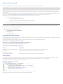
Create a New Project
The first step in writing a C# program with Visual Studio is to choose a project type and create a new Class Library.
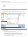
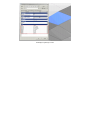
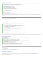
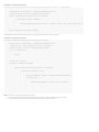
1. From the File menu, select New Project….
2. In the Installed Templates frame, click Visual C#.
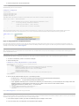
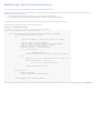
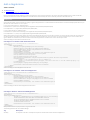
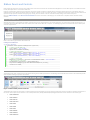
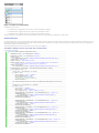
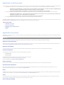
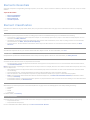
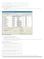
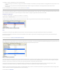
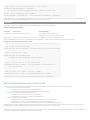
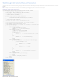
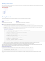
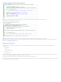
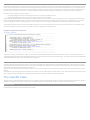
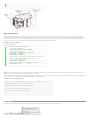
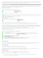
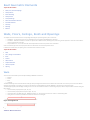
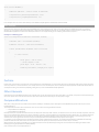
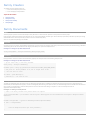
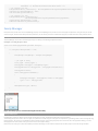
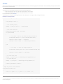
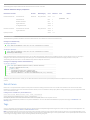
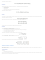
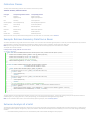
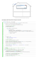
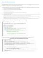
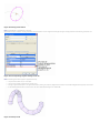
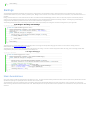
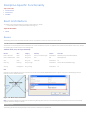
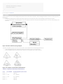
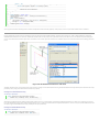
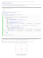
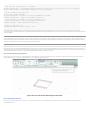
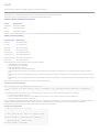
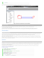
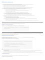
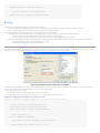
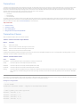
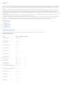
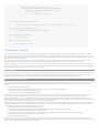
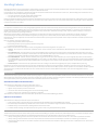
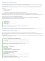
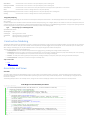
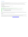
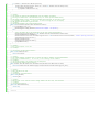
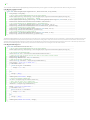
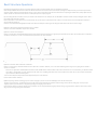
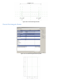
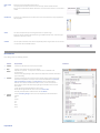
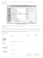
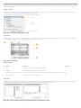
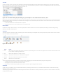
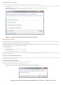
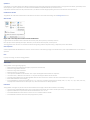
3. In the right-hand frame, click Class Library (see Figure 1: Add New Project below). This walkthrough assumes that the project location is: D:\Sample.
4. In the Name field, type HelloWorld as the project name.
5. Click OK.
Figure 1: Add New Project
Add References
1. To add the RevitAPI reference:
o
From the View menu select Solution Explorer if the Solution Explorer window is not open.
o
In the Solution Explorer, right-click References to display a context menu.
o
From the context menu, click Add Reference. The Add Reference dialog box appears.
o
In the Add Reference dialog box, click the Browse tab. Locate the folder where Revit is installed and click the RevitAPI.dll. For example,
the installed folder location is usually C:\Program Files\Autodesk\Revit Architecture 2012\Program\RevitAPI.dll.
o
Click OK to select the .dll and close the dialog box. RevitAPI appears in the Solution Explorer reference tree.
o
Note: You should always set the Copy Local property of RevitAPI.dll to false for new projects. This saves disk space, and prevents the
Visual Studio debugger from getting confused about which copy of the DLL to use. Right-click the RevitAPI.dll, select Properties, and
change the Copy Local setting from true (the default) to false.
2. Repeat the steps above for the RevitAPIUI.dll.
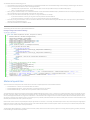
Add Code
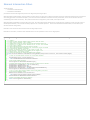
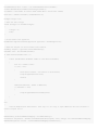
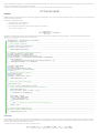
Add the following code to create the add-in:
Code Region 2-1: Getting Started
using System;
using Autodesk.Revit.UI;
using Autodesk.Revit.DB;
namespace HelloWorld
{
[Autodesk.Revit.Attributes.Transaction(Autodesk.Revit.Attributes.TransactionMode.Manual)]
public class Class1 : IExternalCommand
{
public Autodesk.Revit.UI.Result Execute(ExternalCommandData revit,
ref string message, ElementSet elements)
{
TaskDialog.Show("Revit", "Hello World");
return Autodesk.Revit.UI.Result.Succeeded;
}
}
}
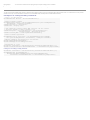
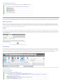
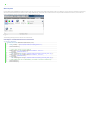
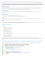
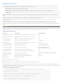
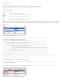
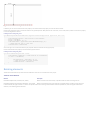
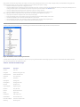
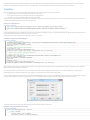
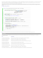
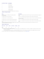
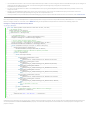
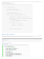
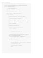
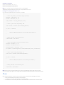
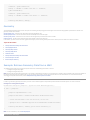
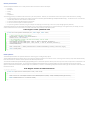
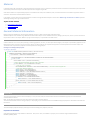
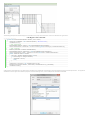
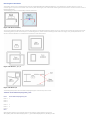
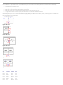
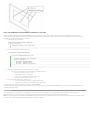
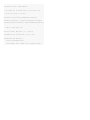
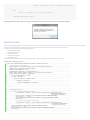
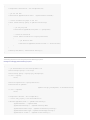
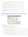
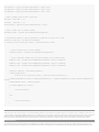
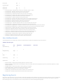
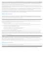
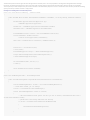
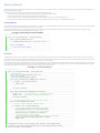
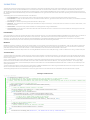
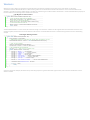
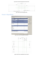
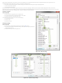
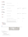
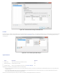
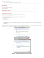
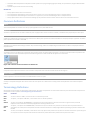
TipThe Visual Studio Intellisense feature can create a skeleton implementation of an interface for you, adding stubs for all the required methods. After you add
":IExternaCommand" after Class1 in the example above, you can select "Implement IExternalCommand" from the Intellisense menu to get the code:
Figure 2: Using Intellisense to Implement Interface
Every Revit add-in application must have an entry point class that implements the IExternalCommand interface, and you must implement the Execute() method. The
Execute() method is the entry point for the add-in application similar to the Main() method in other programs. The add-in entry point class definition is contained in an
assembly. For more details, refer to Add-in Integration.
Build the Program
After completing the code, you must build the file. From the Build menu, click Build Solution. Output from the build appears in the Output window indicating that the
project compiled without errors.
Create a .addin manifest file
The HelloWorld.dll file appears in the project output directory. If you want to invoke the application in Revit, create a manifest file to register it into Revit.
1. To create a manifest file, create a new text file in Notepad.
2. Add the following text:
Code Region 2-2: Creating a .addin manifest file for an external command
<?xml version="1.0" encoding="utf-8" standalone="no"?>
<RevitAddIns>
<AddIn Type="Command">
<Assembly>D:\Sample\HelloWorld\bin\Debug\HelloWorld.dll</Assembly>
<AddInId>239BD853-36E4-461f-9171-C5ACEDA4E721</AddInId>
<FullClassName>HelloWorld.Class1</FullClassName>
<Text>HelloWorld</Text>
<VendorId>ADSK</VendorId>
<VendorDescription>Autodesk, www.autodesk.com</VendorDescription>
</AddIn>
</RevitAddIns>
3. Save the file as HelloWorld.addin and put it in the following location:
o
For Windows XP - C:\Documents and Settings\All Users\Application Data\Autodesk\Revit\Addins\2012\
o
For Vista/Windows 7 - C:\ProgramData\Autodesk\Revit\Addins\2012\
o
If your application assembly dll is on a network share instead of your local hard drive, you must modify Revit.exe.config to allow .NET
assemblies outside your local machine to be loaded. In the "runtime" node in Revit.exe.config, add the element
<loadFromRemoteSources enabled="true"/> " as shown below.
<runtime>
<generatePublisherEvidence enabled="false" />
<loadFromRemoteSources enabled="true"/>
</runtime>
o
o
o
Refer to Add-in Integration for more details using manifest files.
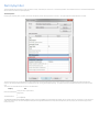
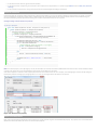
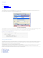
Debug the Add-in
Running a program in Debug mode uses breakpoints to pause the program so that you can examine the state of variables and objects. If there is an error, you can check the
variables as the program runs to deduce why the value is not what you might expect.
1. In the Solution Explorer window, right-click the HelloWorld project to display a context menu.
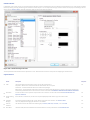
2. From the context menu, click Properties. The Properties window appears.
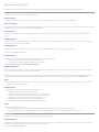
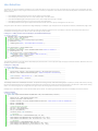
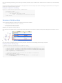
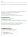
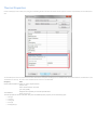
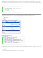
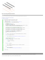
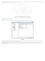
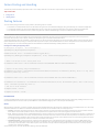
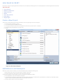
3. Click the Debug tab.
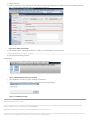
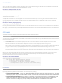
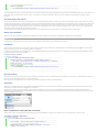
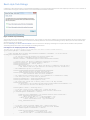
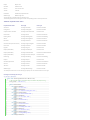
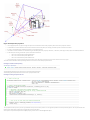
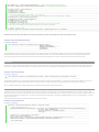
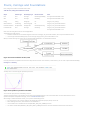
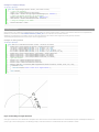
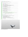
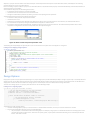
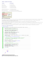
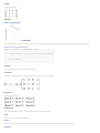
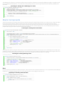
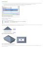
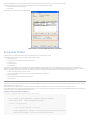
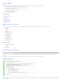
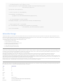
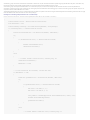
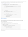
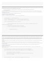
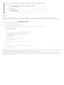
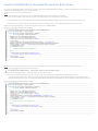
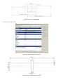
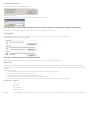
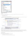
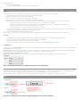
4. Under the Start Action section, click Start external program and browse to the Revit.exe file. By default, the file is located at the following
path, C:\Program Files\Autodesk\Revit Structure 2012\Program\Revit.exe.
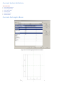
Figure 3: Set debug environment
5. From the Debug menu, select Toggle Breakpoint (or press F9) to set a breakpoint on the following line.
TaskDialog.Show("Revit", "Hello World");
6. Press F5 to start the debug procedure.
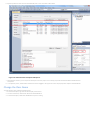
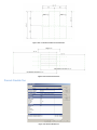
Test debugging:
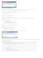
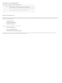
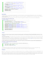
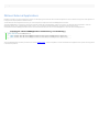
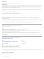
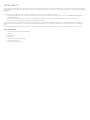
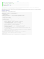
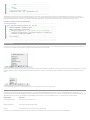
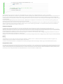
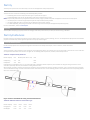
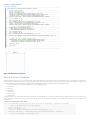
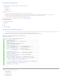
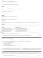
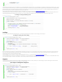
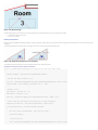
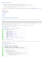
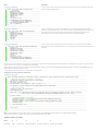
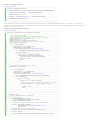
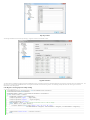
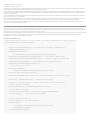
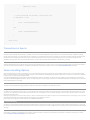
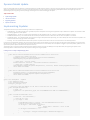
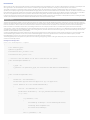
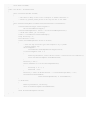
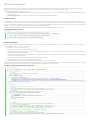
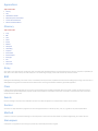
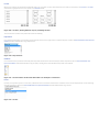
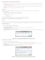
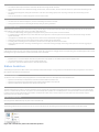
•
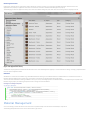
On the Add-Ins tab, HelloWorld appears in the External Tools menu-button.
Figure 4: HelloWorld External Tools command
•
Click HelloWorld to execute the program, activating the breakpoint.
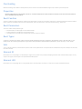
•
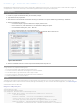
Press F5 to continue executing the program. The following system message appears.
Figure 5: TaskDialog message
Troubleshooting
Q: My add-in application will not compile.
A: If an error appears when you compile the sample code, the problem may be with the version of the RevitAPI used to compile the add-in. Delete the old RevitAPI
reference and load a new one. For more details, refer to Add Reference.
Q: Why is there no Add-Ins tab or why isn't my add-in application displayed under External Tools?
A: In many cases, if an add-in application fails to load, Revit will display an error dialog on startup with information about the failure. For example, if the add-in DLL cannot
be found in the location specified in the manifest file, a message similar to the following appears.
Figure 6: External Tools Error Message
Error messages will also be displayed if the class name specified in ECClassName is not found or does not inherit from IExternalCommand.
However, in some cases, an add-in application may fail to load without any message. Possible causes include:
The add-in application is compiled with a different RevitAPI version
The manifest file is not found
There is a formatting error in the .addin manifest file
Q: Why does my add-in application not work?
A: Even though your add-in application is available under External Tools, it may not work. This is most often caused by an exception in the code.
For example:
Code Region 2-3: Exceptions in Execute()
Command: IExternalCommand
{
A a = new A();//line x
public IExternalCommand.Result Execute ()
{
//…
}
}
Class A
{
//…
}
The following two exceptions clearly identify the problem:
•
An error in line x
•
An exception is thrown in the Execute() method.
Revit will display an error dialog with information about the uncaught exception when the command fails.
Figure 7: Unhandled exception in External Command
This is intended as an aid to debugging your command; commands deployed to users should use try..catch..finally in the example entry method to prevent the exception
from being caught by Revit. Here's an example:
Code Region 2-4: Using try catch in execute:
public IExternalCommand.Result Execute(ExternalCommandData commandData, ref string message, ElementSet elements)
{
ExternalCommandData cdata = commandData;
Autodesk.Revit.ApplicationServices.Application app = cdata.Application;
try
{
// Do some stuff
}
catch (Exception ex)
{
message = ex.Message;
return Autodesk.Revit.UI.Result.Failed;
}
return Autodesk.Revit.UI.Result.Succeeded;
}
Walkthrough: Add Hello World Ribbon Panel
In the Walkthrough: Hello World section you learn how to create an add-in application and invoke it in Revit. You also learn to create a .addin manifest file to register the
add-in application as an external tool. Another way to invoke the add-in application in Revit is through a custom ribbon panel.
Create a New Project
Complete the following steps to create a new project:
1. Create a C# project in Visual Studio using the Class Library template.
2. Type AddPanel as the project name.
3. Add references to the RevitAPI.dll and RevitAPIUI.dll using the directions in the previous walkthrough, Walkthrough: Hello World.
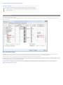
4. Add the PresentationCore reference:
o
In the Solution Explorer, right-click References to display a context menu.
o
From the context menu, click Add Reference. The Add Reference dialog box appears.
o
In the Add Reference dialog box, click the .NET Tab.
o
From the Component Name list, select PresentationCore.
o
Click OK to close the dialog box. PresentationCore appears in the Solution Explorer reference tree.
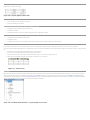
Figure 8: Add Reference
5. Add the WindowsBase reference as well as System.Xaml following similar steps as above.
Change the Class Name
To change the class name, complete the following steps:
1. In the class view window, right-click Class1 to display a context menu.
2. From the context menu, select Rename and change the class' name to CsAddPanel.
3. In the Solution Explorer, right-click the Class1.cs file to display a context.
4. From the context menu, select Rename and change the file's name to CsAddPanel.cs.
5. Double click CsAddPanel.cs to open it for editing.
Add Code
The Add Panel project is different from Hello World because it is automatically invoked when Revit runs. Use the IExternalApplication interface for this project. The
IExternalApplication interface contains two abstract methods, OnStartup() and OnShutdown(). For more information about IExternalApplication, refer to Add-in Integration.
Add the following code for the ribbon panel:
Code Region 2-5: Adding a ribbon panel
using
using
using
class
{
Autodesk.Revit.UI;
Autodesk.Revit.DB;
System.Windows.Media.Imaging;
CsAddpanel : Autodesk.Revit.UI.IExternalApplication
public Autodesk.Revit.UI.Result OnStartup(UIControlledApplication application)
{
// add new ribbon panel
RibbonPanel ribbonPanel = application.CreateRibbonPanel("NewRibbonPanel");
//Create a push button in the ribbon panel "NewRibbonPanel"
//the add-in application "HelloWorld" will be triggered when button is pushed
PushButton pushButton = ribbonPanel.AddItem(new PushButtonData("HelloWorld",
"HelloWorld", @"D:\HelloWorld.dll", "HelloWorld.CsHelloWorld")) as PushButton;
// Set the large image shown on button
Uri uriImage = new Uri(@"D:\Sample\HelloWorld\bin\Debug\39-Globe_32x32.png");
BitmapImage largeImage = new BitmapImage(uriImage);
pushButton.LargeImage = largeImage;
return Result.Succeeded;
}
public Result OnShutdown(UIControlledApplication application)
{
return Result.Succeeded;
}
}
Build the Application
After completing the code, build the application. From the Build menu, click Build Solution. Output from the build appears in the Output window indicating that the project
compiled without errors. AddPanel.dll is located in the project output directory.
Create the .addin manifest file
To invoke the application in Revit, create a manifest file to register it into Revit.
1. Create a new text file using Notepad.
2. Add the following text to the file:
Code Region 2-6: Creating a .addin file for an external application
<?xml version="1.0" encoding="utf-8" standalone="no"?>
<RevitAddIns>
<AddIn Type="Application">
<Name>SampleApplication</Name>
<Assembly>D:\Sample\AddPanel\AddPanel\bin\Debug\AddPanel.dll</Assembly>
<AddInId>604B1052-F742-4951-8576-C261D1993107</AddInId>
<FullClassName>AddPanel.CsAddPanel</FullClassName>
<VendorId>ADSK</VendorId>
<VendorDescription>Autodesk, www.autodesk.com</VendorDescription>
</AddIn>
</RevitAddIns>
3. Save the file as HelloWorldRibbon.addin and put it in the following location:
o
For Windows XP - C:\Documents and Settings\All Users\Application Data\Autodesk\Revit\Addins\2012\
o
For Vista/Windows 7 - C:\ProgramData\Autodesk\Revit\Addins\2012\
Note The AddPanel.dll file is in the default file folder in a new folder called Debug (D:\Sample\HelloWorld\bin\Debug\AddPanel.dll). Use the file path to evaluate Assembly.
Refer to Add-in Integration for more information about .addin manifest files.
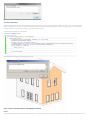
Debugging
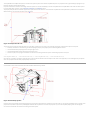
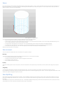
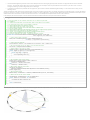
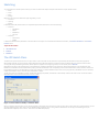
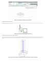
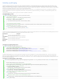
To begin debugging, build the project, and run Revit. A new ribbon panel appears on the Add-Ins tab named NewRibbonPanel and Hello World appears
as the only button on the panel, with a large globe image.
Figure 9: Add a new ribbon panel to Revit
Click Hello World to run the application and display the following dialog box.
Figure 10: Hello World dialog box
Walkthrough: Retrieve Selected Elements
This section introduces you to an add-in application that gets selected elements from Revit.
In add-in applications, you can perform a specific operation on a specific element. For example, you can get or change an element's parameter value. Complete the
following steps to get a parameter value:
1. Create a new project and add the references as summarized in the previous walkthroughs.
2. Use the UIApplication.ActiveUIDocument.Selection.Elements property to retrieve the selected object.
The selected object is a Revit SelElementSet. Use the IEnumerator interface or foreach loop to search the ElementSet.
The following code is an example of how to retrieve selected elements.
Code Region 2-7: Retrieving selected elements
[Autodesk.Revit.Attributes.Transaction(TransactionMode.ReadOnly)]
public class Document_Selection : IExternalCommand
{
public Autodesk.Revit.UI.Result Execute(ExternalCommandData commandData,
ref string message, ElementSet elements)
{
try
{
// Select some elements in Revit before invoking this command
// Get the handle of current document.
UIDocument uidoc = commandData.Application.ActiveUIDocument;
// Get the element selection of current document.
Selection selection = uidoc.Selection;
ElementSet collection = selection.Elements;
if (0 == collection.Size)
{
// If no elements selected.
TaskDialog.Show("Revit","You haven't selected any elements.");
}
else
{
String info = "Ids of selected elements in the document are: ";
foreach (Element elem in collection)
{
info += "\n\t" + elem.Id.IntegerValue;
}
TaskDialog.Show("Revit",info);
}
}
catch (Exception e)
{
message = e.Message;
return Autodesk.Revit.UI.Result.Failed;
}
return Autodesk.Revit.UI.Result.Succeeded;
}
}
After you get the selected elements, you can get the properties or parameters for the elements. For more information, see Parameter.
Walkthrough: Retrieve Filtered Elements
You can use a filter to select only elements that meet certain criteria. For more information on creating and using element filters, see Iterating the Elements Collection.
This example retrieves all the doors in the document and displays a dialog listing their ids.
Code Region 2-8: Retrieve filtered elements
// Create a Filter to get all the doors in the document
ElementClassFilter familyInstanceFilter = new ElementClassFilter(typeof(FamilyInstance));
ElementCategoryFilter doorsCategoryfilter =
new ElementCategoryFilter(BuiltInCategory.OST_Doors);
LogicalAndFilter doorInstancesFilter =
new LogicalAndFilter(familyInstanceFilter, doorsCategoryfilter);
FilteredElementCollector collector = new FilteredElementCollector(document);
ICollection<ElementId> doors = collector.WherePasses(doorInstancesFilter).ToElementIds();
String prompt = "The ids of the doors in the current document are:";
foreach(ElementId id in doors)
{
prompt += "\n\t" + id.IntegerValue;
}
// Give the user some information
TaskDialog.Show("Revit",prompt);
Add-In Integration
Developers add functionality by creating and implementing External Commands and External Applications. Revit identifies the new commands and applications using .addin
manifest files.
•
External Commands appear under the External Tools menu-button on the Add-Ins tab.
•
External Applications are invoked when Revit starts up and unloaded when Revit shuts down
This chapter focuses on the following:
•
Learning how to add functionality using External Commands and External Applications.
•
How to access Revit events.
•
How to customize the Revit UI.
Topics in this section
•
Overview
•
External Commands
•
External Applications
•
DB-Level External Applications
•
Add-in Registration
•
Localization
•
Attributes
•
Revit Exceptions
•
Ribbon Panels and Controls
•
Revit-style Task Dialogs
Overview
The Revit Platform API is based on Revit application functionality. The Revit Platform API is composed of two class Libraries that only work when Revit is running.
The RevitAPI.dll contains methods used to access Revit's application, documents, elements, and parameters at the database level. It also contains
IExternalDBApplication and related interfaces.
The RevitAPIUI.dll contains all API interfaces related to manipulation and customization of the Revit user interface, including:
•
IExternalCommand and External Command related interfaces
•
IExternalApplication and related interfaces
•
Selection
•
RibbonPanel, RibbonItem and subclasses
• TaskDialogs
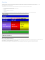
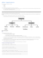
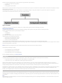
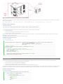
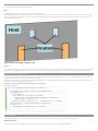
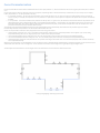
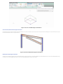
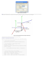
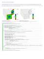
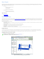
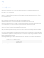
As the following picture shows, Revit Architecture, Revit Structure, and Revit MEP are specific to Architecture, Structure, and MEP respectively.
Figure 11: Revit, RevitAPI and Add-ins
To create a RevitAPI based add-in, you must provide specific entrypoint types in your add-in DLL. These entrypoint classes implement interfaces, either IExternalCommand,
IExternalApplication, or IExternalDBApplication. In this way, the add-in is run automatically on certain events or, in the case of IExternalCommand and
IExternalApplication, manually from the External Tools menu-button.
IExternalCommand, IExternalApplication, IExternalDBApplication, and other available Revit events for add-in integration are introduced in this chapter.
External Commands
Developers can add functionality by implementing External Commands which appear in the External Tools menu-button.
Loading and Running External Commands
When no other commands or edit modes are active in Revit, registered external commands are enabled. When a command is selected, a command object is created and its
Execute() method is called. Once this method returns back to Revit, the command object is destroyed. As a result, data cannot persist in the object between command
executions. However, there are other ways to save data between command executions; for example you can use the Revit shared parameters mechanism to store data in
the Revit project.
You can add External Commands to the External Tools Panel under the External Tools menu-button, or as a custom ribbon panel on the Add-Ins tab, Analyze tab or a new
custom ribbon tab. See the Walkthrough: Hello World and Walkthrough: Add Hello World Ribbon Panel for examples of these two approaches.
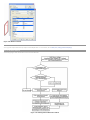
External tools, ribbon tabs and ribbon panels are initialized upon start up. The initialization steps are as follows:
•
•
Revit reads manifest files and identifies:
o
External Applications that can be invoked.
o
External Tools that can be added to the Revit External Tools menu-button.
External Application session adds panels and content to the Add-ins tab.
IExternalCommand
You create an external command by creating an object that implements the IExternalCommand interface. The IExternalCommand interface has one abstract method,
Execute, which is the main method for external commands.
The Execute() method has three parameters:
•
commandData (ExternalCommandData)
•
message (String)
•
elements (ElementSet)
commandData (ExternalCommandData)
The ExternalCommandData object contains references to Application and View which are required by the external command. All Revit data is retrieved directly or indirectly
from this parameter in the external command.
For example, the following statement illustrates how to retrieve Autodesk.Revit.Document from the commandData parameter:
Code Region 3-1: Retrieving the Active Document
Document doc = commandData.Application.ActiveUIDocument.Document;
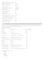
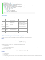
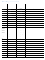
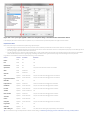
The following table illustrates the ExternalCommandData public properties
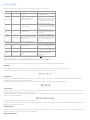
Table 1: ExternalCommandData public properties
Property
Description
Application (Autodesk.Revit.UI.UIApplication)
Retrieves an object that represents the current UIApplication for external command.
JournalData
(IDictionary<String, String>)
A data map that can be used to read and write data to the Revit journal file.
View (Autodesk.Revit.DB.View)
Retrieves an object that represents the View external commands work on.
message (String):
Error messages are returned by an external command using the output parameter message. The string-type parameter is set in the external command process. When
Autodesk.Revit.UI.Result.Failed or Autodesk.Revit.UI.Result.Cancelled is returned, and the message parameter is set, an error dialog appears.
The following code sample illustrates how to use the message parameter.
Code Region 3-2: Setting an error message string
view plaincopy to clipboardprint?
1. class IExternalCommand_message : IExternalCommand
2. {
3.
public Autodesk.Revit.UI.Result Execute(
4.
Autodesk.Revit.ExternalCommandData commandData, ref string message,
5.
Autodesk.Revit.ElementSet elements)
6.
{
7.
message = "Could not locate walls for analysis.";
8.
return Autodesk.Revit.UI.Result.Failed;
9.
}
10. }
Implementing the previous external command causes the following dialog box to appear:
Figure 12: Error message dialog box
elements (ElementSet):
Whenever Autodesk.Revit.UI.Result.Failed or Autodesk.Revit.UI.Result.Canceled is returned and the parameter message is not empty, an error or warning dialog box
appears. Additionally, if any elements are added to the elements parameter, these elements will be highlighted on screen. It is a good practice to set the message
parameter whenever the command fails, whether or not elements are also returned.
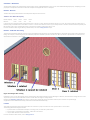
The following code highlights pre-selected walls:
Code Region 3-3: Highlighting walls
view plaincopy to clipboardprint?
1. class IExternalcommand_elements : IExternalCommand
2. {
3.
public Result Execute(
4.
Autodesk.Revit.UI.ExternalCommandData commandData, ref string message,
5.
Autodesk.Revit.DB.ElementSet elements)
6.
{
7.
message = "Please note the highlighted Walls.";
8.
FilteredElementCollector collector = new FilteredElementCollector(commandData.Application.ActiveUIDocument.Document);
9.
ICollection<Element> collection = collector.OfClass(typeof(Wall)).ToElements();
10.
foreach (Element e in collection)
11.
{
12.
elements.Insert(e);
13.
}
14.
15.
return Result.Failed;
16.
}
17. }
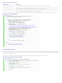
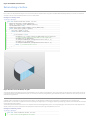
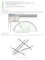
The following picture displays the result of the previous code.
Figure 13: Error message dialog box and highlighted elements
Return
The Return result indicates that the execution failed, succeeded, or is canceled by the user. If it does not succeed, Revit reverses changes made by the external command.
Table 2: IExternalCommand.Result
Member Name
Description
Autodesk.Revit.UI.Result.Succeeded
The external command completed successfully. Revit keeps all changes made by the external command.
Autodesk.Revit.UI.Result.Failed
The external command failed to complete the task. Revit reverses operations performed by the external command. If the message
parameter of Execute is set, Revit displays a dialog with the text "Error - cannot be ignored".
Autodesk.Revit.UI.Result.Cancelled
The user cancelled the external command. Revit reverses changes made by the external command. If the message parameter of
Execute is set, Revit displays a dialog with the text "Warning - can be ignored".
The following example displays a greeting message and allows the user to select the return value. Use the Execute() method as the entrance to the Revit application.
Code Region 3-4: Prompting the user
view plaincopy to clipboardprint?
1. public Autodesk.Revit.UI.Result Execute(ExternalCommandData commandData,
2.
ref string message, ElementSet elements)
3. {
4.
try
5.
{
6.
Document doc = commandData.Application.ActiveUIDocument.Document;
7.
UIDocument uidoc = commandData.Application.ActiveUIDocument;
8.
// Delete selected elements
9.
ICollection<Autodesk.Revit.DB.ElementId> ids =
10.
doc.Delete(uidoc.Selection.GetElementIds());
11.
12.
TaskDialog taskDialog = new TaskDialog("Revit");
13.
taskDialog.MainContent =
14.
("Click Yes to return Succeeded. Selected members will be deleted.\n" +
15.
"Click No to return Failed. Selected members will not be deleted.\n" +
16.
"Click Cancel to return Cancelled. Selected members will not be deleted.");
17.
TaskDialogCommonButtons buttons = TaskDialogCommonButtons.Yes |
18.
TaskDialogCommonButtons.No | TaskDialogCommonButtons.Cancel;
19.
taskDialog.CommonButtons = buttons;
20.
TaskDialogResult taskDialogResult = taskDialog.Show();
21.
22.
if (taskDialogResult == TaskDialogResult.Yes)
23.
{
24.
return Autodesk.Revit.UI.Result.Succeeded;
25.
}
26.
else if (taskDialogResult == TaskDialogResult.No)
27.
{
28.
elements = uidoc.Selection.Elements;
29.
message = "Failed to delete selection.";
30.
return Autodesk.Revit.UI.Result.Failed;
31.
}
32.
else
33.
{
34.
return Autodesk.Revit.UI.Result.Cancelled;
35.
}
36.
}
37.
catch
38.
{
39.
message = "Unexpected Exception thrown.";
40.
return Autodesk.Revit.UI.Result.Failed;
41.
}
42. }
IExternalCommandAvailability
This interface allows you control over whether or not an external command button may be pressed. The IsCommandAvailable interface method passes the application and
a set of categories matching the categories of selected items in Revit to your implementation. The typical use would be to check the selected categories to see if they meet
the criteria for your command to be run.
In this example the accessibility check allows a button to be clicked when there is no active selection, or when at least one wall is selected:
Code Region 3-5: Setting Command Availability
view plaincopy to clipboardprint?
1. public class SampleAccessibilityCheck : IExternalCommandAvailability
2. {
3.
public bool IsCommandAvailable(AutodeskAutodesk.Revit.UI.UIApplication applicationData,
4.
CategorySet selectedCategories)
5.
{
6.
// Allow button click if there is no active selection
7.
if (selectedCategories.IsEmpty)
8.
return true;
9.
// Allow button click if there is at least one wall selected
10.
foreach (Category c in selectedCategories)
11.
{
12.
if (c.Id.IntegerValue == (int)BuiltInCategory.OST_Walls)
13.
return true;
14.
}
15.
return false;
16.
}
External Application
Table of contents
1. 1. IExternalApplication
Developers can add functionality through External Applications as well as External Commands. Ribbon tabs and ribbon panels are customized using the External Application.
Ribbon panel buttons are bound to an External command.
IExternalApplication
To add an External Application to Revit, you create an object that implements the IExternalApplication interface.
The IExternalApplication interface has two abstract methods, OnStartup() and OnShutdown(), which you override in your external application. Revit calls OnStartup() when
it starts, and OnShutdown() when it closes.
This is the OnStartup() and OnShutdown() abstract definition:
Code Region 3-6: OnShutdown() and OnStartup()
public interface IExternalApplication
{
public Autodesk.Revit.UI.Result OnStartup(UIControlledApplication application);
public Autodesk.Revit.UI.Result OnShutdown(UIControlledApplication application);
}
The UIControlledApplication parameter provides access to certain Revit events and allows customization of ribbon panels and controls and the addition of ribbon tabs. For
example, the public event DialogBoxShowing of UIControlledApplication can be used to capture the event of a dialog being displayed. The following code snippet registers
the handling function that is called right before a dialog is shown.
Code Region 3-7: DialogBoxShowing Event
application.DialogBoxShowing += new
EventHandler<Autodesk.Revit.Events.DialogBoxShowingEventArgs>(AppDialogShowing);
The following code sample illustrates how to use the UIControlledApplication type to register an event handler and process the event when it occurs.
Code Region 3-8: Using ControlledApplication
public class Application_DialogBoxShowing : IExternalApplication
{
// Implement the OnStartup method to register events when Revit starts.
public Result OnStartup(UIControlledApplication application)
{
// Register related events
application.DialogBoxShowing +=
new EventHandler<Autodesk.Revit.UI.Events.DialogBoxShowingEventArgs>(AppDialogShowing);
return Result.Succeeded;
}
// Implement this method to unregister the subscribed events when Revit exits.
public Result OnShutdown(UIControlledApplication application)
{
// unregister events
application.DialogBoxShowing -=
new EventHandler<Autodesk.Revit.UI.Events.DialogBoxShowingEventArgs>(AppDialogShowing);
return Result.Succeeded;
}
// The DialogBoxShowing event handler, which allow you to
// do some work before the dialog shows
void AppDialogShowing(object sender, DialogBoxShowingEventArgs args)
{
// Get the help id of the showing dialog
int dialogId = args.HelpId;
// Format the prompt information string
String promptInfo = "A Revit dialog will be opened.\n";
promptInfo += "The help id of this dialog is " + dialogId.ToString() + "\n";
promptInfo += "If you don't want the dialog to open, please press cancel button";
// Show the prompt message, and allow the user to close the dialog directly.
TaskDialog taskDialog = new TaskDialog("Revit");
taskDialog.MainContent = promptInfo;
TaskDialogCommonButtons buttons = TaskDialogCommonButtons.Ok |
TaskDialogCommonButtons.Cancel;
taskDialog.CommonButtons = buttons;
TaskDialogResult result = taskDialog.Show();
if (TaskDialogResult.Cancel == result)
{
// Do not show the Revit dialog
args.OverrideResult(1);
}
else
{
// Continue to show the Revit dialog
args.OverrideResult(0);
}
}
}
Add-in Registration
Table of contents
1. 1. Manifest Files
2. 2. .NET Add-in Utility for manifest files
External commands and external applications need to be registered in order to appear inside Revit. They can be registered by adding them to a .addin manifest file.
The order that external commands and applications are listed in Revit is determined by the order in which they are read in when Revit starts up.
Manifest Files
Starting with Revit 2011, the Revit API offers the ability to register API applications via a .addin manifest file. Manifest files are read automatically by Revit when they are
placed in one of two locations on a user's system:
In a non-user-specific location in "application data":
For Windows XP - C:\Documents and Settings\All Users\Application Data\Autodesk\Revit\Addins\2012\
For Vista/Windows 7 - C:\ProgramData\Autodesk\Revit\Addins\2012\
In a user-specific location in "application data":
For Windows XP - C:\Documents and Settings\<user>\Application Data\Autodesk\Revit\Addins\2012\
For Vista/Windows 7 - C:\Users\<user>\AppData\Roaming\Autodesk\Revit\Addins\2012\
All files named .addin in these locations will be read and processed by Revit during startup. All of the files in both the user-specific location and the all users location are
considered together and loaded in alphabetical order. If an all users manifest file shares the same name with a user-specific manifest file, the all users manifest file is
ignored. Within each manifest file, the external commands and external applications are loaded in the order in which they are listed.
A basic file adding one ExternalCommand looks like this:
Code Region 3-9: Manifest .addin ExternalCommand
<?xml version="1.0" encoding="utf-8" standalone="no"?>
<RevitAddIns>
<AddIn Type="Command">
<Assembly>c:\MyProgram\MyProgram.dll</Assembly>
<AddInId>76eb700a-2c85-4888-a78d-31429ecae9ed</AddInId>
<FullClassName>Revit.Samples.SampleCommand</FullClassName>
<Text>Sample command</Text>
<VendorId>ADSK</VendorId>
<VendorDescription>Autodesk, www.autodesk.com</VendorDescription>
<VisibilityMode>NotVisibleInFamily</VisibilityMode>
<Discipline>Structure</Discipline>
<Discipline>Architecture</Discipline>
<AvailabilityClassName>Revit.Samples.SampleAccessibilityCheck</AvailabilityClassName>
<LongDescription>
<p>This is the long description for my command.</p>
<p>This is another descriptive paragraph, with notes about how to use the command properly.</p>
</LongDescription>
<TooltipImage>c:\MyProgram\Autodesk.png</TooltipImage>
<LargeImage>c:\MyProgram\MyProgramIcon.png</LargeImage>
</AddIn>
</RevitAddIns>
A basic file adding one ExternalApplication looks like this:
Code Region 3-10: Manifest .addin ExternalApplication
<?xml version="1.0" encoding="utf-8" standalone="no"?>
<RevitAddIns>
<AddIn Type="Application">
<Name>SampleApplication</Name>
<Assembly>c:\MyProgram\MyProgram.dll</Assembly>
<AddInId>604B1052-F742-4951-8576-C261D1993107</AddInId>
<FullClassName>Revit.Samples.SampleApplication</FullClassName>
<VendorId>ADSK</VendorId>
<VendorDescription>Autodesk, www.autodesk.com</VendorDescription>
</AddIn>
</RevitAddIns>
A basic file adding one DB-level External Application looks like this:
Code Region: Manifest .addin ExternalDBApplication
<?xml version="1.0" encoding="utf-8" standalone="no"?>
<RevitAddIns>
<AddIn Type="DBApplication">
<Assembly>c:\MyDBLevelApplication\MyDBLevelApplication.dll</Assembly>
<AddInId>DA3D570A-1AB3-4a4b-B09F-8C15DFEC6BF0</AddInId>
<FullClassName>MyCompany.MyDBLevelAddIn</FullClassName>
<Name>My DB-Level AddIn</Name>
<VendorId>ADSK</VendorId>
<VendorDescription>Autodesk, www.autodesk.com</VendorDescription>
</AddIn>
</RevitAddIns>
Multiple AddIn elements may be provided in a single manifest file.
The following table describes the available XML tags:
Tag
Description
Assembly
The full path to the add-in assembly file. Required for all ExternalCommands and ExternalApplications.
FullClassName
The full name of the class in the assembly file which implements IExternalCommand or IExternalApplication. Required for all ExternalCommands
and ExternalApplications.
AddInId
A GUID which represents the id of this particular application. AddInIds must be unique for a given session of Revit.
Autodesk recommends you generate a unique GUID for each registered application or command. Required for all ExternalCommands and
ExternalApplications.
Name
The name of application. Required; for ExternalApplications only.
Text
The name of the button. Optional; use this tag for ExternalCommands only. The default is "External Tool".
VendorId
A string conforming to the Autodesk vendor ID standard. Required for all ExternalCommands and ExternalApplications.
Register your vendor id string with Autodesk at http://www.autodesk.com/symbreg.
VendorDescription
Description containing vendor's legal name and/or other pertinent information. Optional.
Description
Short description of the command, will be used as the button tooltip. Optional; use this tag for ExternalCommands only.
The default is a tooltip with just the command text.
VisibilityMode
The modes in which the external command will be visible. Multiple values may be set for this option. Optional; use this tag for ExternalCommands
only.
The default is to display the command in all modes, including when there is no active document. Previously written external commands which
need to run against the active document should either be modified to ensure that the code deals with invocation of the command when there is
no active document, or apply the NotVisibleWhenNoActiveDocument mode. See table below for more information.
Discipline
The disciplines in which the external command will be visible. Multiple values may be set for this option. Optional; use this tag for
ExternalCommands only.
The default is to display the command in all disciplines. If any specific disciplines are listed, the command will only be visible in those disciplines.
See table below for more information.
AvailabilityClassName
The full name of the class in the assembly file which implemented IExternalCommandAvailability. This class allows the command button to be
selectively grayed out depending on context. Optional; use this tag for ExternalCommands only.
The default is a command that is available whenever it is visible.
LargeImage
The icon to use for the button in the External Tools pulldown menu. Optional; use this tag for ExternalCommands only.
The default is to show a button without an icon.
SmallImage
The icon to use if the button is promoted to the Quick Access Toolbar. Optional; use this tag for ExternalCommands only.
The default is to show a Quick Access Toolbar button without an icon, which can be confusing to users.
LongDescription
Long description of the command, will be used as part of the button extended tooltip, shown when the mouse hovers over the command for a
longer amount of time. Optional; use this tag for ExternalCommands only. If this property and TooltipImage are not supplied, the button will not
have an extended tooltip.
TooltipImage
An image file to show as a part of the button extended tooltip, shown when the mouse hovers over the command for a longer amount of time.
Optional; use this tag for ExternalCommands only. If this property and TooltipImage are not supplied, the button will not have an extended tooltip.
LanguageType
Localization setting for Text, Description, LargeImage, LongDescription, and TooltipImage of external tools buttons. Revit will load the resource
values from the specified language resource dll. The value can be one of the eleven languages supported by Revit. If no LanguageType is specified,
the language resource which the current session of Revit is using will be automatically loaded. For more details see the section on Localization.
Table 3: VisibilityMode Members
Member Name
Description
AlwaysVisible
The command is available in all possible modes supported by the Revit API.
NotVisibleInProject
The command is invisible when there is a project document active.
NotVisibleInFamily
The command is invisible when there is a family document active.
NotVisibleWhenNoActiveDocument
The command is invisible when there is no active document.
Table 4: Discipline Members
Member Name
Description
Any
The command is available in all possible disciplines supported by the Revit API.
Architecture
The command is visible in Autodesk Revit Architecture.
Structure
The command is visible in Autodesk Revit Structure.
StructuralAnalysis
The command is visible when the Structural Analysis discipline editing tools are available.
MassingAndSite
The command is visible when the Massing and Site discipline editing tools are available.
EnergyAnalysis
The command is visible when Energy Analysis discipline editing tools are available.
Mechanical
The command is visible when the Mechanical discipline editing tools are available, e.g. in Autodesk Revit MEP.
Electrical
The command is visible when the Electrical discipline editing tools are available, e.g. in Autodesk Revit MEP.
Piping
The command is visible when the Piping discipline editing tools are available, e.g. in Autodesk Revit MEP.
MechanicalAnalysis
The command is visible when the Mechanical Analysis discipline editing tools are available.
PipingAnalysis
The command is visible when the Piping Analysis discipline editing tools are available.
ElectricalAnalysis
The command is visible when the Electrical Analysis discipline editing tools are available.
.NET Add-in Utility for manifest files
The .NET utility DLL RevitAddInUtility.dll offers a dedicated API capable of reading, writing and modifying Revit Add-In manifest files. It is intended for use from product
installers and scripts. Consult the API documentation in the RevitAddInUtility.chm help file in the SDK installation folder.
Code Region 3-11: Creating and editing a manifest file
//create a new addin manifest
RevitAddInManifest Manifest = new RevitAddInManifest();
//create an external command
RevitAddInCommand command1 = new RevitAddInCommand("full path\\assemblyName.dll",
Guid.NewGuid(), "namespace.className");
command1.Description = "description";
command1.Text = "display text";
// this command only visible in Revit MEP, Structure, and only visible
// in Project document or when no document at all
command1.Discipline = Discipline.Mechanical | Discipline.Electrical |
Discipline.Piping | Discipline.Structure;
command1.VisibilityMode = VisibilityMode.NotVisibleInFamily;
//create an external application
RevitAddInApplication application1 = new RevitAddInApplication("appName",
"full path\\assemblyName.dll", Guid.NewGuid(), "namespace.className");
//add both command(s) and application(s) into manifest
Manifest.AddInCommands.Add(command1);
Manifest.AddInApplications.Add(application1);
//save manifest to a file
RevitProduct revitProduct1 = RevitProductUtility.GetAllInstalledRevitProducts()[0];
Manifest.SaveAs(revitProduct1.AllUsersAddInFolder + "\\RevitAddInUtilitySample.addin");
Code Region 3-12: Reading an existing manifest file
RevitProduct revitProduct1 = RevitProductUtility.GetAllInstalledRevitProducts()[0];
RevitAddInManifest revitAddInManifest =
Autodesk.RevitAddIns.AddInManifestUtility.GetRevitAddInManifest(
revitProduct1.AllUsersAddInFolder + "\\RevitAddInUtilitySample.addin");
Localization
You can let Revit localize the user-visible resources of an external command button (including Text, large icon image, long and short descriptions and tooltip image). You will
need to create a .NET Satellite DLL which contains the strings, images, and icons for the button. Then change the values of the tags in the .addin file to correspond to the
names of resources in the Satellite dll, but prepended with the @character. So the tag:
Code Region 3-13: Non-localized Text Entry
<Text>Extension Manager</Text>
Becomes:
Code Region 3-14: Localized Text Entry
<Text>@ExtensionText</Text>
where ExtensionText is the name of the resource found in the Satellite DLL.
The Satellite DLLs are expected to be in a directory with the name of the language of the language-culture, such as en or en-US. The directory should be located in the
directory that contains the add-in assembly. See http://msdn.microsoft.com/en-us/library/e9zazcx5.aspx to create managed Satellite DLLs.
You can force Revit to use a particular language resource DLL, regardless of the language of the Revit session, by specifying the language and culture explicitly with a
LanguageType tag.
Code Region 3-15: Using LanguageType Tag
<LanguageType>English_USA</LanguageType>
For example, the entry above would force Revit to always load the values from the en-US Satellite DLL and to ignore the current Revit language and culture settings when
considering the localizable members of the external command manifest file.
Revit supports the 11 languages defined in the Autodesk.Revit.ApplicationServices.LanguageType enumerated type: English_USA, German, Spanish, French, Italian, Dutch,
Chinese_Simplified, Chinese_Traditional, Japanese, Korean, and Russian.
Attributes
The Revit API provides several attributes for configuring ExternalCommand and ExternalApplication behavior.
TransactionAttribute
The custom attribute Autodesk.Revit.Attributes.TransactionMode must be applied to your implementation class of the IExternalCommand interface to control transaction
behavior for external command. There is no default for this option. This mode controls how the API framework expects transactions to be used when the command is
invoked. The supported values are:
•
TransactionMode.Automatic - Revit will create a transaction in the active document before the external command is executed and the transaction will be
committed or rolled back after the command is completed (based upon the return value of the ExternalCommand callback). The command cannot create and start
its own Transactions, but it can create SubTransactions. The command must report its success or failure status with the Result return value.
•
TransactionMode.Manual - Revit will not create a transaction (but it will create an outer transaction group to roll back all changes if the external command returns
a failure). Instead, you may use combinations of Transactions, SubTransactions, and TransactionGroups as you please. You will have to follow all rules regarding use
of transactions and related classes. You will have to give your transactions names which will then appear in the Undo menu. Revit will check that all transactions
(also groups and sub-transactions) are properly closed upon return from an external command. If not, Revit will discard all changes made to the model.
•
TransactionMode.ReadOnly - No transaction (nor group) will be created, and no transaction may be created for the lifetime of the command. The External
Command may only use methods that read from the model. Exceptions will be thrown if the command either tries to start a transaction (or group) or attempts to
write to the model.
In all three modes, the TransactionMode applies only to the active document. You may open other documents during the course of the command, and you may have
complete control over the creation and use of Transactions, SubTransactions, and TransactionGroups on those other documents (even in ReadOnly mode).
For example, to set an external command to use automatic transaction mode:
Code Region 3-18: TransactionAttribute
[Transaction(TransactionMode.Automatic)]
public class Command : IExternalCommand
{
public Autodesk.Revit.IExternalCommand.Result Execute(
Autodesk.Revit.ExternalCommandData commandData,
ref string message, Autodesk.Revit.DB.ElementSet elements)
{
// Command implementation, which modifies the active document directly
// and no need to start/commit transaction.
}
}
See Transactions.
JournalingAttribute
The custom attribute Autodesk.Revit.Attributes.JournalingAttribute can optionally be applied to your implementation class of the IExternalCommand interface to control
the journaling behavior during the external command execution. There are two options for journaling:
•
JournalMode.NoCommandData - Contents of the ExternalCommandData.JournalData map are not written to the Revit journal. This option
allows Revit API calls to write to the journal as needed. This option allows commands which invoke the Revit UI for selection or responses to
task dialogs to replay correctly.
•
JournalMode.UsingCommandData - Uses the IDictionary<String, String> supplied in the command data. This will hide all Revit journal
entries between the external command invocation and the IDictionary<String, String> entry. Commands which invoke the Revit UI for
selection or responses to task dialogs may not replay correctly. This is the default if the JournalingAttribute is not specified.
Code Region 3-19: JournalingAttribute
[Journaling(JournalingMode.UsingCommandData)]
public class Command : IExternalCommand
{
public Autodesk.Revit.IExternalCommand.Result Execute(
Autodesk.Revit.ExternalCommandData commandData,
ref string message, Autodesk.Revit.DB.ElementSet elements)
{
return Autodesk.Revit.UI.Result.Succeeded;
}
}
Revit Exceptions
When API methods encounter a non-fatal error, they throw an exception. Exceptions should be caught by Revit add-ins. The Revit API help file specifies exceptions that are
typically encountered for specific methods. All Revit API methods throw a subclass of Autodesk.Revit.Exceptions.ApplicationException. These exceptions closely mirror
standard .NET exceptions such as:
•
ArgumentException
•
InvalidOperationException
•
FileNotFoundException
However, some of these subclasses are unique to Revit:
•
AutoJoinFailedException
•
RegenerationFailedException
•
ModificationOutsideTransactionException
In addition, there is a special exception type called InternalException, which represents a failure path which was not anticipated. Exceptions of this type carry extra
diagnostic information which can be passed back to Autodesk for diagnosis.
Ribbon Panels and Controls
Revit provides API solutions to integrate custom ribbon panels and controls. These APIs are used with IExternalApplication. Custom ribbon panels can be added to the AddIns tab, the Analyze tab or to a new custom ribbon tab.
Panels can include buttons, both large and small, which can be either simple push buttons, pulldown buttons containing multiple commands, or split buttons which are
pulldown buttons with a default push button attached. In addition to buttons, panels can include radio groups, combo boxes and text boxes. Panels can also include vertical
separators to help separate commands into logical groups. Finally, panels can include a slide out control accessed by clicking on the bottom of the panel.
Please see Ribbon Guidelines in the API User Interface Guidelines section for information on developing a user interface that is compliant with the standards used by
Autodesk.
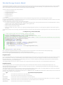
Create a New Ribbon Tab
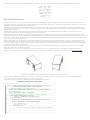
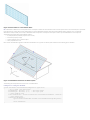
Although ribbon panels can be added to the Add-Ins or Analyze tab, they can also be added to a new custom ribbon tab. This option should only be used if necessary. To
ensure that the standard Revit ribbon tabs remain visible, a limit of 20 custom ribbon tabs is imposed. The following image shows a new ribbon tab with one ribbon panel
and a few simple controls.
Below is the code that generated the above ribbon tab.
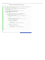
Code Region: New Ribbon tab
view plaincopy to clipboardprint?
1. publicResult OnStartup(UIControlledApplication application)
2. {
3.
// Create a custom ribbon tab
4.
String tabName = "This Tab Name";
5.
application.CreateRibbonTab(tabName);
6.
7.
// Create two push buttons
8.
PushButtonData button1 = newPushButtonData("Button1", "My Button #1",
9.
@"C:\ExternalCommands.dll", "Revit.Test.Command1");
10.
PushButtonData button2 = newPushButtonData("Button2", "My Button #2",
11.
@"C:\ExternalCommands.dll", "Revit.Test.Command2");
12.
13.
// Create a ribbon panel
14.
RibbonPanel m_projectPanel = application.CreateRibbonPanel(tabName, "This Panel Name");
15.
// Add the buttons to the panel
16.
List<RibbonItem> projectButtons = newList<RibbonItem>();
17.
projectButtons.AddRange(m_projectPanel.AddStackedItems(button1, button2));
18.
19.
returnResult.Succeeded;
20. }
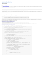
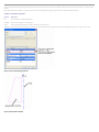
Create a New Ribbon Panel and Controls
The following image shows a ribbon panel on the Add-Ins tab using various ribbon panel controls. The following sections describe these controls in more detail and provide
code samples for creating each portion of the ribbon.
Figure 14: New ribbon panel and controls
The following code outlines the steps taken to create the ribbon panel pictured above. Each of the functions called in this sample is provided in subsequent samples later in
this section. Those samples assume that there is an assembly located at D:\ Sample\HelloWorld\bin\Debug\Hello.dll which contains the External Command Types:
•
Hello.HelloButton
•
Hello.HelloOne
•
Hello.HelloTwo
•
Hello.HelloThree
•
Hello.HelloA
•
Hello.HelloB
•
Hello.HelloC
•
Hello.HelloRed
•
Hello.HelloBlue
•
Hello.HelloGreen
Code Region: Ribbon panel and controls
view plaincopy to clipboardprint?
1. public Result OnStartup(Autodesk.Revit.UI.UIControlledApplication app)
2. {
3.
RibbonPanel panel = app.CreateRibbonPanel("New Ribbon Panel");
4.
5.
AddRadioGroup(panel);
6.
panel.AddSeparator();
7.
AddPushButton(panel);
8.
AddSplitButton(panel);
9.
AddStackedButtons(panel);
10.
AddSlideOut(panel);
11.
12.
return Result.Succeeded;
13. }
Ribbon Panel
Custom ribbon panels can be added to the Add-Ins tab (the default) or the Analyze tab, or they can be added to a new custom ribbon tab. There are various types of ribbon
controls that can be added to ribbon panels which are discussed in more detail in the next section. All ribbon controls have some common properties and functionality.
Ribbon Control Classes
Each ribbon control has two classes associated with it - one derived from RibbonItemData that is used to create the control (i.e. SplitButtonData) and add it to a ribbon
panel and one derived from RibbonItem (i.e. SplitButton) which represents the item after it is added to a panel. The properties available from RibbonItemData (and the
derived classes) are also available from RibbonItem (and the corresponding derived classes). These properties can be set prior to adding the control to the panel or can be
set using the RibbonItem class after it has been added to the panel.
Tooltips
Most controls can have a tooltip set (using the ToolTip property) which is displayed when the user moves the mouse over the control. When the user hovers the mouse
over a control for an extended period of time, an extended tooltip will be displayed using the LongDescription and the ToolTipImage properties. If neither LongDescription
nor ToolTipImage are set, the extended tooltip is not displayed. If no ToolTip is provided, then the text of the control (RibbonItem.ItemText) is displayed when the mouse
moves over the control.
Figure 15: Extended Tooltip
Contextual Help
Controls can have contextual help associated with them. When the user hovers the mouse over the control and hits F1, the contextual help is triggered. Contextual help
options include linking to an external URL, launching a locally installed help (chm) file, or linking to a topic on the Autodesk help wiki. The ContextualHelp class is used to
create a type of contextual help, and then RibbonItem.SetContextualHelp() (or RibbonItemData.SetContextualHelp()) associates it with a control. When a ContextualHelp
instance is associated with a control, the text "Press F1 for more help" will appear below the tooltip when the mouse hovers over the control, as shown below.
The following example associates a new ContextualHelp with a push button control. Pressing F1 when hovered over the push button will open the Autodesk homepage in a
new browser window.
Code Region: Contextual Help
view plaincopy to clipboardprint?
1. private void AddPushButton(RibbonPanel panel)
2. {
3.
PushButton pushButton = panel.AddItem(new PushButtonData("HelloWorld",
4.
"HelloWorld", @"D:\Sample\HelloWorld\bin\Debug\HelloWorld.dll", "HelloWorld.CsHelloWorld")) as PushButton;
5.
6.
// Set ToolTip and contextual help
7.
pushButton.ToolTip = "Say Hello World";
8.
ContextualHelp contextHelp = new ContextualHelp(ContextualHelpType.Url,
9.
"http://www.autodesk.com");
10.
pushButton.SetContextualHelp(contextHelp);
11.
12.
13.
14.
15. }
// Set the large image shown on button
pushButton.LargeImage =
new BitmapImage(new Uri(@"D:\Sample\HelloWorld\bin\Debug\39-Globe_32x32.png"));
The ContextualHelp class has a Launch() method that can be called to display the help topic specified by the contents of this ContextualHelp object at any time, the same as
when the F1 key is pressed when the control is active. This allows the association of help topics with user interface components inside dialogs created by an add-in
application.
Associating images with controls
All of these controls can have an image associated with them using the LargeImage property. The best size for images associated with large controls, such as non-stacked
ribbon and drop-down buttons, is 32×32 pixels, but larger images will be adjusted to fit the button. Stacked buttons and small controls such as text boxes and combo boxes
should have a 16×16 pixel image set. Large buttons should also have a 16×16 pixel image set for the Image property. This image is used if the command is moved to the
Quick Access Toolbar. If the Image property is not set, no image will be displayed if the command is moved to the Quick Access Toolbar. Note that if an image larger than
16×16 pixels is used, it will NOT be adjusted to fit the toolbar.
The ToolTipImage will be displayed below the LongDescription in the extended tooltip, if provided. There is no recommended size for this image.
Ribbon control availability
Ribbon controls can be enabled or disabled with the RibbonItem.Enabled property or made visible or invisible with the RibbonItem.Visible property.
Ribbon Controls
In addition to the following controls, vertical separators can be added to ribbon panels to group related sets of controls.
Push Buttons
There are three types of buttons you can add to a panel: simple push buttons, drop-down buttons, and split buttons. The HelloWorld button in Figure 13 is a push button.
When the button is pressed, the corresponding command is triggered.
In addition to the Enabled property, PushButton has the AvailabilityClassName property which can be used to set the name of an IExternalCommandAvailability interface
that controls when the command is available.
Code Region: Adding a push button
view plaincopy to clipboardprint?
1. private void AddPushButton(RibbonPanel panel)
2. {
3.
PushButton pushButton = panel.AddItem(new PushButtonData("HelloWorld",
4.
"HelloWorld", @"D:\HelloWorld.dll", "HelloWorld.CsHelloWorld")) as PushButton;
5.
6.
pushButton.ToolTip = "Say Hello World";
7.
// Set the large image shown on button
8.
pushButton.LargeImage =
9.
new BitmapImage(new Uri(@"D:\Sample\HelloWorld\bin\Debug\39-Globe_32x32.png"));
10. }
Drop-down buttons
Drop-down buttons expand to display two or more commands in a drop-down menu. In the Revit API, drop-down buttons are referred to as PulldownButtons. Horizontal
separators can be added between items in the drop-down menu.
Each command in a drop-down menu can also have an associated LargeImage as shown in the example above.
Split buttons
Split buttons are drop-down buttons with a default push button attached. The top half of the button works like a push button while the bottom half functions as a dropdown button. The Option One button in Figure 13 is a split button.
Initially, the push button will be the top item in the drop-down list. However, by using the IsSynchronizedWithCurrentItem property, the default command (which is
displayed as the push button top half of the split button) can be synchronized with the last used command. By default it will be synched. Selecting Option Two in the split
button from Figure 13 above yields:
Figure 16: Split button synchronized with current item
Note that the ToolTip, ToolTipImage and LongDescription properties for SplitButton are ignored. The tooltip for the current push button is shown instead.
Code Region: Adding a split button
view plaincopy to clipboardprint?
1. private void AddSplitButton(RibbonPanel panel)
2. {
3.
string assembly = @"D:\Sample\HelloWorld\bin\Debug\Hello.dll";
4.
5.
// create push buttons for split button drop down
6.
PushButtonData bOne = new PushButtonData("ButtonNameA", "Option One",
7.
assembly, "Hello.HelloOne");
8.
9.
10.
11.
12.
13.
14.
15.
16.
17.
18.
19.
20.
21.
22.
23.
24.
25.
26. }
bOne.LargeImage =
new BitmapImage(new Uri(@"D:\Sample\HelloWorld\bin\Debug\One.bmp"));
PushButtonData bTwo = new PushButtonData("ButtonNameB", "Option Two",
assembly, "Hello.HelloTwo");
bTwo.LargeImage =
new BitmapImage(new Uri(@"D:\Sample\HelloWorld\bin\Debug\Two.bmp"));
PushButtonData bThree = new PushButtonData("ButtonNameC", "Option Three",
assembly, "Hello.HelloThree");
bThree.LargeImage =
new BitmapImage(new Uri(@"D:\Sample\HelloWorld\bin\Debug\Three.bmp"));
SplitButtonData sb1 = new SplitButtonData("splitButton1", "Split");
SplitButton sb = panel.AddItem(sb1) as SplitButton;
sb.AddPushButton(bOne);
sb.AddPushButton(bTwo);
sb.AddPushButton(bThree);
Radio buttons
A radio button group is a set of mutually exclusive toggle buttons; only one can be selected at a time. After adding a RadioButtonGroup to a panel, use the AddItem() or
AddItems() methods to add toggle buttons to the group. Toggle buttons are derived from PushButton. The RadioButtonGroup.Current property can be used to access the
currently selected button.
Note that tooltips do not apply to radio button groups. Instead, the tooltip for each toggle button is displayed as the mouse moves over the individual buttons.
Code Region: Adding radio button group
view plaincopy to clipboardprint?
1. private void AddRadioGroup(RibbonPanel panel)
2. {
3.
// add radio button group
4.
RadioButtonGroupData radioData = new RadioButtonGroupData("radioGroup");
5.
RadioButtonGroup radioButtonGroup = panel.AddItem(radioData) as RadioButtonGroup;
6.
7.
// create toggle buttons and add to radio button group
8.
ToggleButtonData tb1 = new ToggleButtonData("toggleButton1", "Red");
9.
tb1.ToolTip = "Red Option";
10.
tb1.LargeImage = new BitmapImage(new Uri(@"D:\Sample\HelloWorld\bin\Debug\Red.bmp"));
11.
ToggleButtonData tb2 = new ToggleButtonData("toggleButton2", "Green");
12.
tb2.ToolTip = "Green Option";
13.
tb2.LargeImage = new BitmapImage(new Uri(@"D:\Sample\HelloWorld\bin\Debug\Green.bmp"));
14.
ToggleButtonData tb3 = new ToggleButtonData("toggleButton3", "Blue");
15.
tb3.ToolTip = "Blue Option";
16.
tb3.LargeImage = new BitmapImage(new Uri(@"D:\Sample\HelloWorld\bin\Debug\Blue.bmp"));
17.
radioButtonGroup.AddItem(tb1);
18.
radioButtonGroup.AddItem(tb2);
19.
radioButtonGroup.AddItem(tb3);
20. }
Text box
A text box is an input control for users to enter text. The image for a text box can be used as a clickable button by setting the ShowImageAsButton property to true. The
default is false. The image is displayed to the left of the text box when ShowImageAsButton is false, and displayed at the right end of the text box when it acts as a button,
as in Figure 13.
The text entered in the text box is only accepted if the user hits the Enter key or if they click the associated image when the image is shown as a button. Otherwise, the text
will revert to its previous value.
In addition to providing a tooltip for a text box, the PromptText property can be used to indicate to the user what type of information to enter in the text box. Prompt text
is displayed when the text box is empty and does not have keyboard focus. This text is displayed in italics. The text box in Figure 13 has the prompt text "Enter a comment".
The width of the text box can be set using the Width property. The default is 200 device-independent units.
The TextBox.EnterPressed event is triggered when the user presses enter, or when they click on the associated image for the text box when ShowImageAsButton is set to
true. When implementing an EnterPressed event handler, cast the sender object to TextBox to get the value the user has entered as shown in the following example.
Code Region: TextBox.EnterPressed event handler
view plaincopy to clipboardprint?
1. void ProcessText(object sender, Autodesk.Revit.UI.Events.TextBoxEnterPressedEventArgs args)
2. {
3.
// cast sender as TextBox to retrieve text value
4.
TextBox textBox = sender as TextBox;
5.
string strText = textBox.Value as string;
6. }
The inherited ItemText property has no effect for TextBox. The user-entered text can be obtained from the Value property, which must be converted to a string.
See the section on stacked ribbon items for an example of adding a TextBox to a ribbon panel, including how to register the event above.
Combo box
A combo box is a pulldown with a set of selectable items. After adding a ComboBox to a panel, use the AddItem() or AddItems() methods to add ComboBoxMembers to the
list.
Separators can also be added to separate items in the list or members can be optionally grouped using the ComboBoxMember.GroupName property. All members with the
same GroupName will be grouped together with a header that shows the group name. Any items not assigned a GroupName will be placed at the top of the list. Note that
when grouping items, separators should not be used as they will be placed at the end of the group rather than in the order they are added.
Figure 17: Combo box with grouping
ComboBox has three events:
•
CurrentChanged - triggered when the current item of the ComboBox is changed
•
DropDownClosed - triggered when the drop-down of the ComboBox is closed
• DropDownClosed - triggered when the drop-down of the ComboBox is opened
See the code region in the following section on stacked ribbon items for a sample of adding a ComboBox to a ribbon panel.
Stacked Panel Items
To conserve panel space, you can add small panel items in stacks of two or three. Each item in the stack can be a push button, a drop-down button, a combo box or a text
box. Radio button groups and split buttons cannot be stacked. Stacked buttons should have an image associated through their Image property, rather than LargeImage. A
16×16 image is ideal for small stacked buttons.
The following example produces the stacked text box and combo box in Figure 13.
Code Region: Adding a text box and combo box as stacked items
view plaincopy to clipboardprint?
1. private void AddStackedButtons(RibbonPanel panel)
2. {
3.
ComboBoxData cbData = new ComboBoxData("comboBox");
4.
5.
TextBoxData textData = new TextBoxData("Text Box");
6.
textData.Image =
7.
new BitmapImage(new Uri(@"D:\Sample\HelloWorld\bin\Debug\39-Globe_16x16.png"));
8.
textData.Name = "Text Box";
9.
textData.ToolTip = "Enter some text here";
10.
textData.LongDescription = "<p>This is text that will appear next to the image</p>"
11.
+ "<p>when the user hovers the mouse over the control</p>";
12.
textData.ToolTipImage =
13.
new BitmapImage(new Uri(@"D:\Sample\HelloWorld\bin\Debug\39-Globe_32x32.png"));
14.
15.
IList<RibbonItem> stackedItems = panel.AddStackedItems(textData, cbData);
16.
if (stackedItems.Count > 1)
17.
{
18.
TextBox tBox = stackedItems[0] as TextBox;
19.
if (tBox != null)
20.
{
21.
tBox.PromptText = "Enter a comment";
22.
tBox.ShowImageAsButton = true;
23.
tBox.ToolTip = "Enter some text";
24.
// Register event handler ProcessText
25.
tBox.EnterPressed +=
26.
new EventHandler<Autodesk.Revit.UI.Events.TextBoxEnterPressedEventArgs>(ProcessText);
27.
}
28.
29.
ComboBox cBox = stackedItems[1] as ComboBox;
30.
if (cBox != null)
31.
{
32.
cBox.ItemText = "ComboBox";
33.
cBox.ToolTip = "Select an Option";
34.
cBox.LongDescription = "Select a number or letter";
35.
36.
ComboBoxMemberData cboxMemDataA = new ComboBoxMemberData("A", "Option A");
37.
cboxMemDataA.Image =
38.
new BitmapImage(new Uri(@"D:\Sample\HelloWorld\bin\Debug\A.bmp"));
39.
cboxMemDataA.GroupName = "Letters";
40.
cBox.AddItem(cboxMemDataA);
41.
42.
ComboBoxMemberData cboxMemDataB = new ComboBoxMemberData("B", "Option B");
43.
cboxMemDataB.Image =
44.
new BitmapImage(new Uri(@"D:\Sample\HelloWorld\bin\Debug\B.bmp"));
45.
cboxMemDataB.GroupName = "Letters";
46.
cBox.AddItem(cboxMemDataB);
47.
48.
ComboBoxMemberData cboxMemData = new ComboBoxMemberData("One", "Option 1");
49.
cboxMemData.Image =
50.
new BitmapImage(new Uri(@"D:\Sample\HelloWorld\bin\Debug\One.bmp"));
51.
cboxMemData.GroupName = "Numbers";
52.
cBox.AddItem(cboxMemData);
53.
ComboBoxMemberData cboxMemData2 = new ComboBoxMemberData("Two", "Option 2");
54.
cboxMemData2.Image =
55.
new BitmapImage(new Uri(@"D:\Sample\HelloWorld\bin\Debug\Two.bmp"));
56.
cboxMemData2.GroupName = "Numbers";
57.
cBox.AddItem(cboxMemData2);
58.
ComboBoxMemberData cboxMemData3 = new ComboBoxMemberData("Three", "Option 3");
59.
cboxMemData3.Image =
60.
new BitmapImage(new Uri(@"D:\Sample\HelloWorld\bin\Debug\Three.bmp"));
61.
cboxMemData3.GroupName = "Numbers";
62.
cBox.AddItem(cboxMemData3);
63.
}
64.
}
65. }
Slide-out panel
Use the RibbonPanel.AddSlideOut() method to add a slide out to the bottom of the ribbon panel. When a slide-out is added, an arrow is shown on the bottom of the panel,
which when clicked will display the slide-out. After calling AddSlideOut(), subsequent calls to add new items to the panel will be added to the slide-out, so the slide-out
must be added after all other controls have been added to the ribbon panel.
Figure 18: Slide-out
The following example produces the slide-out shown above:
Code Region: TextBox.EnterPressed event handler
view plaincopy to clipboardprint?
1. private static void AddSlideOut(RibbonPanel panel)
2. {
3.
string assembly = @"D:\Sample\HelloWorld\bin\Debug\Hello.dll";
4.
5.
panel.AddSlideOut();
6.
7.
// create some controls for the slide out
8.
PushButtonData b1 = new PushButtonData("ButtonName1", "Button 1",
9.
assembly, "Hello.HelloButton");
10.
b1.LargeImage =
11.
new BitmapImage(new Uri(@"D:\Sample\HelloWorld\bin\Debug\39-Globe_32x32.png"));
12.
PushButtonData b2 = new PushButtonData("ButtonName2", "Button 2",
13.
assembly, "Hello.HelloTwo");
14.
b2.LargeImage =
15.
new BitmapImage(new Uri(@"D:\Sample\HelloWorld\bin\Debug\39-Globe_16x16.png"));
16.
17.
// items added after call to AddSlideOut() are added to slide-out automatically
18.
panel.AddItem(b1);
19.
panel.AddItem(b2);
Revit-style Task Dialogs
A TaskDialog is a Revit-style alternative to a simple Windows MessageBox. It can be used to display information and receive simple input from the user. It has a common set
of controls that are arranged in a standard order to assure consistent look and feel with the rest of Revit.
Figure 19: Revit-style Task Dialog
There are two ways to create and show a task dialog to the user. The first option is to construct the TaskDialog, set its properties individually, and use the instance method
Show() to show it to the user. The second is to use one of the static Show() methods to construct and show the dialog in one step. When you use the static methods only a
subset of the options can be specified.
Please see Task Dialog in the API User Interface Guidelines section for information on developing a task dialog that is compliant with the standards used by Autodesk.
The following example shows how to create and display the task dialog shown above.
Code Region 3-27: Displaying Revit-style TaskDialog
[Autodesk.Revit.Attributes.Transaction(Autodesk.Revit.Attributes.TransactionMode.Automatic)]
class TaskDialogExample : IExternalCommand
{
public Autodesk.Revit.UI.Result Execute(ExternalCommandData commandData, ref string message,
Autodesk.Revit.DB.ElementSet elements)
{
// Get the application and document from external command data.
Application app = commandData.Application.Application;
Document activeDoc = commandData.Application.ActiveUIDocument.Document;
// Creates a Revit task dialog to communicate information to the user.
TaskDialog mainDialog = new TaskDialog("Hello, Revit!");
mainDialog.MainInstruction = "Hello, Revit!";
mainDialog.MainContent =
"This sample shows how to use a Revit task dialog to communicate with the user."
+ "The command links below open additional task dialogs with more information.";
// Add commmandLink options to task dialog
mainDialog.AddCommandLink(TaskDialogCommandLinkId.CommandLink1,
"View information about the Revit installation");
mainDialog.AddCommandLink(TaskDialogCommandLinkId.CommandLink2,
"View information about the active document");
// Set common buttons and default button. If no CommonButton or CommandLink is added,
// task dialog will show a Close button by default
mainDialog.CommonButtons = TaskDialogCommonButtons.Close;
mainDialog.DefaultButton = TaskDialogResult.Close;
// Set footer text. Footer text is usually used to link to the help document.
mainDialog.FooterText =
"<a href=\"http://usa.autodesk.com/adsk/servlet/index?siteID=123112&id=2484975 \">"
+ "Click here for the Revit API Developer Center</a>";
TaskDialogResult tResult = mainDialog.Show();
// If the user clicks the first command link, a simple Task Dialog
// with only a Close button shows information about the Revit installation.
if (TaskDialogResult.CommandLink1 == tResult)
{
TaskDialog dialog_CommandLink1 = new TaskDialog("Revit Build Information");
dialog_CommandLink1.MainInstruction =
"Revit Version Name is: " + app.VersionName + "\n"
+ "Revit Version Number is: " + app.VersionNumber + "\n"
+ "Revit Version Build is: " + app.VersionBuild;
dialog_CommandLink1.Show();
}
// If the user clicks the second command link, a simple Task Dialog
// created by static method shows information about the active document
else if (TaskDialogResult.CommandLink2 == tResult)
{
TaskDialog.Show("Active Document Information",
"Active document: " + activeDoc.Title + "\n"
+ "Active view name: " + activeDoc.ActiveView.Name);
}
return Autodesk.Revit.UI.Result.Succeeded;
}
}
DB-level External Applications
Database-level add-ins are External Applications that do not add anything to the Revit UI. DB-level External Applications can be used when the purpose of the application is
to assign events and/or updaters to the Revit session.
To add a DB-level External Application to Revit, you create an object that implements the IExternalDBApplication interface.
The IExternalDBApplication interface has two abstract methods, OnStartup() and OnShutdown(), which you override in your DB-level external application. Revit calls
OnStartup() when it starts, and OnShutdown() when it closes. This is very similar to IExternalApplication, but note that these methods return
Autodesk.Revit.DB.ExternalDBApplicationResult rather than Autodesk.Revit.UI.Result and use ControlledApplication rather than UIControlledApplication.
Code Region: IExternalDBApplication OnShutdown() and OnStartup()
view plaincopy to clipboardprint?
1. public interface IExternalDBApplication
2. {
3.
public Autodesk.Revit.DB.ExternalDBApplicationResult OnStartup(ControlledApplication application);
4.
public Autodesk.Revit.DB.ExternalDBApplicationResult OnShutdown(ControlledApplication application);
5. }
The ControlledApplication parameter provides access to Revit database events. Events and Updaters to which the database-level application will respond can be registered
in the OnStartup method.
Application and Document
The top level objects in the Revit Platform API are application and document. These are represented by the classes Application, UIApplication, Document and UIDocument.
• The application object refers to an individual Revit session, providing access to documents, options, and other application-wide data and settings.
•
•
o
Autodesk.Revit.UI.UIApplication - provides access to UI-level interfaces for the application, including the ability to add RibbonPanels
to the user interface, and the ability to obtain the active document in the user interface.
o
Autodesk.Revit.ApplicationServices.Application - provides access to all other application level properties.
The document object is a single Revit project file representing a building model. Revit can have multiple projects open and multiple views for one project.
o
Autodesk.Revit.UI.UIDocument - provides access to UI-level interfaces for the document, such as the contents of the selection and
the ability to prompt the user to make selections and pick points
o
Autodesk.Revit.DB.Document - provides access to all other document level properties
If multiple documents are open, the active document is the one whose view is active in the Revit session.
This chapter identifies all Application and Document functions, and then focuses on file management, settings, and units. For more details about the Element class, refer to
Elements Essentials and Editing Elements and refer to the Views for more details about the view elements.
Topics in this section
•
•
•
•
•
Application Functions
Document Functions
Document and File Management
Settings
Units
Application Functions
Application functions provide access to documents, objects, and other application data and settings. All Application and UIApplication functions are identified and defined
in the following sections.
Application
The class represents the Autodesk Revit Application, providing access to documents, options and other application wide data and settings.
Application Version Information
Application properties include VersionBuild, VersionNumber and VersionName. These can be used to provide add-in behavior based on the release and build of Revit, as
shown in How to use Application properties to enforce a correct version for your add-in.
Application-wide Settings
The SharedParametersFilename property and GetLibraryPaths() and SetLibraryPaths() methods provide access to these application-wide settings.
Document Management
The Application class provides methods to create the following types of documents:
• Family document
• Project document
• Project template
The OpenDocumentFile() method can be used to open any of these document types.
All open documents can be retrieved using the Documents property.
For more details, see Document and Management.
Session Information
Properties such as UserName and methods such as GetRevitServerNetworkHosts() provide read-only access to this session specific information.
Shared Parameter Management
Revit uses one shared parameter file at a time. The Application.OpenSharedParameterFile() method accesses the shared parameter file whose path is set in the
SharedParametersFilename property. For more details, see Shared Parameter.
Events
The Application class exposes document and application events such as document open and save. Subscribing to these events notifies the application when the events are
enabled and acts accordingly. For more details, see Access to Revit Event in the Add-In Integration section.
Create
The Create property returns an Object Factory used to create application-wide utility and geometric objects in the Revit Platform API. Create is used when you want to
create an object in the Revit application memory rather than your application's memory.
Failure Posting and Handling
The FailureDefinitionRegistry, which contains all registered FailureDefinitions is available from the static GetFailureDefinitionRegistry() method. The static method
RegisterFailuresProcessor() can be used to register a custom IFailuresProcessor. For more information on posting and handling failures, see Failure Posting and Handling.
UIApplication
This class represents an active session of the Autodesk Revit user interface, providing access to UI customization methods, events, and the active document.
Document Management
The UIApplication provides access to the active document using the UIActiveDocument property. Additionally, a Revit document may be opened using the overloaded
OpenAndActivateDocument() method. The document will be opened with the default view active. This method may not be called inside a transaction and may only be
invoked during an event when no active document is open yet in Revit and the event is not nested inside another event.
Add-in Management
The ActiveAddInId property gets the current active external application or external command id, while the LoadedApplications property returns an array of successfully
loaded external applications.
Ribbon Panel Utility
Use the UIApplication object to add new ribbon panels and controls to Revit.
For more details, see Ribbon Panel and Controls in the Add-In Integration section.
Extents
The DrawingAreaExtents property returns a rectangle that represents the screen pixel coordinates of drawing area, while the MainWindowExtents property returns the
rectangle that represents the screen pixel coordinates of the Revit main window
Events
The UIApplication class exposes UI related events such as when a dialog box is displayed. Subscribing to these events notifies the application when the events are enabled
and acts accordingly. For more details, see Access to Revit Event in the Add-In Integration section.
Discipline Controls
The properties:
• Application.IsArchitectureEnabled
• Application.IsStructureEnabled
• Application.IsStructuralAnalysisEnabled
• Application.IsMassingEnabled
• Application.IsEnergyAnalysisEnabled
• Application.IsSystemsEnabled
• Application.IsMechanicalEnabled
• Application.IsMechanicalAnalysisEnabled
• Application.IsElectricalEnabled
• Application.IsElectricalAnalysisEnabled
• Application.IsPipingEnabled
• Application.IsPipingAnalysisEnabled
provide read and modify access to the available disciplines. An application can read the properties to determine when to enable or disable aspects of it's UI.
When a discipline's status is toggled, Revit's UI will be adjusted, and certain operations and features will be enabled or disabled as appropriate. Enabling an analysis mode
will only take effect if the corresponding discipline is enabled. For example, enabling mechanical analysis will not take effect unless the mechanical discipline is also
enabled.
How to use Application properties to enforce a correct version for your add-in
Sometimes you need your add-in to operate only in the presence of a particular Update Release of Revit due to the presence of specific fixes or compatible APIs. The
following sample code demonstrates a technique to determine if the Revit version is any Update Release after the initial known Revit release.
Code Region: Use VersionBuild to identify if your add-in is compatible
view plaincopy to clipboardprint?
1. public void GetVersionInfo(Autodesk.Revit.ApplicationServices.Application app)
2. {
3.
// 20110309_2315 is the datecode of the initial release of Revit 2012
4.
if (app.VersionNumber == "2012" &&
5.
String.Compare(app.VersionBuild, "20110309_2315") > 0)
6.
{
7.
TaskDialog.Show("Supported version",
8.
"This application supported in this version.");
9.
}
10.
else
11.
{
12.
TaskDialog dialog = new TaskDialog("Unsupported version.");
13.
dialog.MainIcon = TaskDialogIcon.TaskDialogIconWarning;
14.
dialog.MainInstruction = "This application is only supported in Revit 2012 UR1 and later.";
15.
dialog.Show();
16.
}
Document Functions
Document stores the Revit Elements, manages the data, and updates multiple data views. The Document class mainly provides the following functions.
Document
The Document class represents an open Autodesk Revit project.
Settings Property
The Settings property returns an object that provides access to general components within Revit projects. For more details, see Settings.
Place and Locations
Each project has only one site location that identifies the physical project location on Earth. There can be several project locations for one project. Each location is an offset,
or rotation, of the site location. For more details, see Place and Locations.
Type Collections
Document provides properties such as FloorTypes, WallTypes, and so on. All properties return a collection object containing the corresponding types loaded into the
project.
View Management
A project document can have multiple views. The ActiveView property returns a View object representing the active view. You can filter the elements in the project to
retrieve other views. For more details, see Views.
Element Retrieval
The Document object stores elements in the project. Retrieve specific elements by ElementId or UniqueId using the Element property.
For more details, see Elements Essential.
File Management
Each Document object represents a Revit project file. Document provides the following functions:
• Retrieve file information such as file path name and project title.
• Provides Close() and Save() methods to close and save the document.
For more details, see Document and File management.
Element Management
Revit maintains all Element objects in a project. To create new elements, use the Create property which returns an Object Factory used to create new project element
instances in the Revit Platform API, such as FamilyInstance or Group.
The Document class can also be used to delete elements. Use the Delete() method to delete an element in the project. Deleted elements and any dependent elements are
not displayed and are removed from the Document. References to deleted elements are invalid and cause an exception. For more details, see Editing Element.
Events
Events are raised on certain actions, such as when you save a project using Save or Save As. To capture the events and respond in the application, you must register the
event handlers. For more details, see Events.
Document Status
Several properties provide information on the status of the document:
• IsModifiable - whether the document may be modified
• IsModified - whether the document was changed since it was opened or saved
• IsReadOnly - whether the document is currently read only or can be modified
• IsReadOnlyFile - whether the document was opened in read-only mode
• IsFamilyDocument - whether the document is a family document
• IsWorkshared - whether worksets have been enabled in the document
Others
Document also provides other functions:
• ParameterBindings Property - Mapping between parameter definitions and categories. For more details, see Shared Parameter.
• ReactionsAreUpToDate Property - Reports whether the reactionary loads changed. For more details, see Loads in the Revit Structure section.
UIDocument
The UIDocument class represents an Autodesk Revit project opened in the Revit user interface.
Element Retrieval
Retrieve selected elements using the Selection property in UIDocument. This property returns an object representing the active selection containing the selected project
elements. It also provides UI interaction methods to pick objects in the Revit model.
For more details, see Elements Essential.
Element Display
The ShowElements() method uses zoom to fit to focus in on one more elements.
View Management
The UIDocument class can be used to refresh the active view in the active document by calling the RefreshActiveView() method. The ActiveView property can be used to
retrieve or set the active view for the document. Changing the active view has some restrictions. It can only be used in an active document, which must not be in read-only
state and must not be inside a transaction. Additionally, the active view may not be changed during the ViewChanging or ViewChanged event, or during any pre-action
event, such as DocumentSaving, DocumentExporting, or other similar events.
The UIDocument can also be used to get a list of all open view windows in the Revit user interface. The GetOpenUIViews method returns a list of UIViews which contain
data about the view windows in the Revit user interface.
Document and File Management
Document and file management make it easy to create and find your documents.
Document Retrieval
The Application class maintains all documents. As previously mentioned, you can open more than one document in a session. The active document is retrieved using the
UIApplication class property, ActiveUIDocument.
All open documents, including the active document, are retrieved using the Application class Documents property. The property returns a set containing all open
documents in the Revit session.
Document File Information
The Document class provides two properties for each corresponding file, PathName, and Title.
• PathName returns the document's fully qualified file path. The PathName returns an empty string if the project has not been saved since it was created.
• Title is the project title, which is usually derived from the project filename. The returned value varies based on your system settings.
Open a Document
The Application class provides an overloaded method to open an existing project file:
Table 3: Open Document in API
Method
Event
Document OpenDocumentFile(string filename )
Document OpenDocumentFile(ModelPath modelPath, OpenOptions openOptions)
DocumentOpened
When you specify a string with a fully qualified file path, Revit opens the file and creates a Document instance. Use this method to open a file on other computers by
assigning the files Universal Naming Conversion (UNC) name to this method.
The file can be a project file with the extension .rvt, a family file with the extension .rfa, or a template file with the extension .rte. The method throws
Autodesk.Revit.Exceptions.InvalidOperationException if you try to open unsupported file types. If the document is opened successfully, the DocumentOpened event is
raised.
The second overload takes a path to the model as a ModelPath rather than a string and the OpenOptions parameter offerst the ability to detach the opened document
from central if applicable.
Create a Document
Create new documents using the Application methods in the following table.
Table 4: Create Document in the API
Method
Event
view plaincopy to clipboardprint?
DocumentCreated
view plaincopy to clipboardprint?
DocumentCreated
view plaincopy to clipboardprint?
DocumentCreated
1. Document NewProjectDocument(string templateFileName);
1. Document NewFamilyDocument(string templateFileName);
1. Document NewProjectTemplateDocument(string templateFilename);
Each method requires a template file name as the parameter. The created document is returned based on the template file.
Save and Close a Document
The Document class provides methods to save or close instances.
Table 5: Save and Close Document in API
Method
Event
Save()
DocumentSaved
SaveAs()
DocumentSavedAs
Close()
DocumentClosed
SaveAs() has 3 overloads. Two overloads take the filename as an argument and but an exception will be thrown if another file exists with the given filename. The third
overload takes a filename as an argument as well as a second argument that specifies whether to rename the file and/or whether to overwrite and existing file, if it exists.
Close() has two overloads. One takes a Boolean argument that indicates whether to save the file before closing it. The second overload takes no arguments and if the
document was modified, the user will be asked if they want to save the file before closing. This method will throw an exception if the document's path name is not already
set or if the saving target file is read-only.
Note
The Close() method does not affect the active document or raise the DocumentClosed event, because the document is used by an external application. You can only call this
method on non-active documents.
The UIDocument class also provides methods to save and close instances.
Table 6: Save and Close UIDocument in API
Method
Event
SaveAndClose()
DocumentSaved, DocumentClosed
SaveAs()
DocumentSavedAs
SaveAndClose() closes the document after saving it. If the document's path name has not been set the "Save As" dialog will be shown to the Revit user to set its name and
location.
The SaveAs() method saves the document to a file name and path obtained from the Revit user via the "Save As" dialog.
Document Preview
The DocumentPreviewSettings class can be obtained from the Document and contains the settings related to the saving of preview images for a given document.
Code Region: Document Preview
view plaincopy to clipboardprint?
1. public void SaveActiveViewWithPreview(UIApplication application)
2. {
3.
// Get the handle of current document.
4.
Autodesk.Revit.DB.Document document = application.ActiveUIDocument.Document;
5.
6.
// Get the document's preview settings
7.
DocumentPreviewSettings settings = document.GetDocumentPreviewSettings();
8.
9.
// Find a candidate 3D view
10.
FilteredElementCollector collector = new FilteredElementCollector(document);
11.
collector.OfClass(typeof(View3D));
12.
13.
Func<View3D, bool> isValidForPreview = v => settings.IsViewIdValidForPreview(v.Id);
14.
15.
View3D viewForPreview = collector.OfType<View3D>().First<View3D>(isValidForPreview);
16.
17.
// Set the preview settings
18.
Transaction setTransaction = new Transaction(document, "Set preview view id");
19.
setTransaction.Start();
20.
settings.PreviewViewId = viewForPreview.Id;
21.
setTransaction.Commit();
22.
23.
// Save the document
24.
document.Save();
25. }
Load Family
The Document class provides you with the ability to load an entire family and all of its symbols into the project. Because loading an entire family can take a long time and a
lot of memory, the Document class provides a similar method, LoadFamilySymbol() to load only specified symbols.
For more details, see Loading Families.
Settings
The following table identifies the commands in the Revit Platform UI Manage tab, and corresponding APIs.
Table 7: Settings in API and UI
UI command
Associated API
Reference
Settings
Project Information
Document.ProjectInformation
See the following note
Settings
Project Parameters
Document.ParameterBindings (Only for Shared Parameter)
See Shared Parameter
Document.ProjectLocations
Document.ActiveProjectLocation
See Place and Locations
FilteredElementCollector filtering on class FillPatternElement
See the following note
Project Location panel
Settings
Additional Settings
Fill Patterns
Settings
Materials
Document.Settings.Materials
See Materials Management
Settings
Object Styles
Document.Settings.Categories
See the following note
Phasing
Phases
Document.Phases
See the following note
Settings
Structural Settings
Load related structural settings are available in the API
See Revit Structure
Settings
Project Units
Document.ProjectUnit
See Unit
Document.Settings.VoumeCalculationSetting
See the following note
Area and Volume Calculations (on the Room & Area panel)
Note
•
Project Information - The API provides the ProjectInfo class which is retrieved using Document.ProjectInformation to represent project information in the Revit
project. The following table identifies the corresponding APIs for the Project Information parameters.
Table 8: ProjectInformation
Parameters
Corresponding API
Built-in Parameters
Project Issue Date
ProjectInfo.IssueDate
PROJECT_ISSUE_DATE
Project Status
ProjectInfo.Status
PROJECT_STATUS
Client Name
ProjectInfo.ClientName
CLIENT_NAME
Project Address
ProjectInfo.Address
PROJECT_ADDRESS
Project Name
ProjectInfo.Name
PROJECT_NAME
Project Number
ProjectInfo.Number
PROJECT_NUMBER
Use the properties exposed by ProjectInfo to retrieve and set all strings. These properties are implemented by the corresponding built-in parameters. You can get or set the
values through built-in parameters directly. For more information about how to gain access to these parameters through the built-in parameters, see Parameter in the
Elements Essential section. The recommended way to get project information is to use the ProjectInfo properties.
•
Fill Patterns - Retrieve all Fill Patterns in the current document using a FilteredElementCollector filtering on class FillPatternElement. Specific FillPatterns can be
retrieved using the static methods FillPatternElement.GetFillPattern(Document, ElementId) or FillPatternElement.GetFillPatternByName (Document, string).
•
Object Styles - Use Settings.Categories to retrieve all information in Category objects except for Line Style. For more details, see Categories in the Elements
Essentialand Material sections.
•
Phases - Revit maintains the element lifetime by phases, which are distinct time periods in the project lifecycle. All phases in a document are retrieved using the
Document.Phases property. The property returns an array containing Phase class instances. However, the Revit API does not expose functions from the Phase class.
•
Options - The Options command configures project global settings. You can retrieve an Options.Application instance using the Application.Options property.
Currently, the Options.Application class only supports access to library paths and shared parameters file.
•
Area and Volume Calculations - The Document.Settings.VolumeCalculationSetting allows you to enable or disable volume calculations, and to change the room
boundary location.
Units
The Revit Unit System is based on seven base units for seven base quantities that are independent. The base units are identified in the following table.
Table 9: 7 Base Units in Revit Unit System
Base Unit
Unit In Revit
Unit System
Length
Feet (ft)
Imperial
Angle
Radian
Metric
Mass
Kilogram (kg)
Metric
Time
Seconds (s)
Metric
Electric Current
Ampere (A)
Metric
Temperature
Kelvin (K)
Metric
Luminous Intensity
Candela (cd)
Metric
Note Since Revit stores lengths in feet and other basic quantities in metric units, a derived unit involving length will be a non-standard unit based on both the Imperial and
the Metric systems. For example, since a force is measured in "mass-length per time squared", it is stored in kg-ft / s2.
The Revit Platform API provides access to project units and format via the Document.ProjectUnit. The APIs that provide access to Project units and format settings include
the following:
Table 10: Project Unit Properties
UI Command
Corresponding Type in API
Access API
Slope
Enums.RiseRunOrAngleType
ProjectUnit.Slope
Decimal symbol
Enums.DecimalSymbolType
ProjectUnit.DecimalSymbolType
Discipline
Enums.UnitDiscipline
ProjectUnit.FormatOptions.Discipline
Units
Enums.DisplayUnitType
ProjectUnit.FormatOptions.Units
Rounding
System.Double
ProjectUnit.FormatOptions.Rounding
Unit suffix
Enums.UnitSuffixType
ProjectUnit.FormatOptions.Unitsuffix
Elements Essentials
An Element corresponds to a single building or drawing component, such as a door, a wall, or a dimension. In addition, an Element can be a door type, a view, or a material
definition.
Topics in this section
•
•
•
•
Element Classification
Other Classifications
Element Retrieval
General Properties
Element Classification
Revit Elements are divided into six groups: Model, Sketch, View, Group, Annotation and Information. Each group contains related Elements and their corresponding
symbols.
Model Elements
Model Elements represent physical items that exist in a building project. Elements in the Model Elements group can be subdivided into the following:
• Family Instances - Family Instances contain family instance objects. You can load family objects into your project or create them from family templates. For more
information, see Family Instances.
• Host Elements - Host Elements contain system family objects that can contain other model elements, such as wall, roof, ceiling, and floor. For more information
about Host Elements, see Walls, Floors, Roofs and Openings.
•
Structure Elements. - Structure Elements contain elements that are only used in Revit Structure. For more information about Structure Elements, see Revit
Structure.
View Elements
View Elements represent the way you view and interact with other objects in Revit. For more information, see Views.
Group Elements
Group Elements represent the assistant Elements such as Array and Group objects in Revit. For more information, see Editing Elements.
Annotation and Datum Elements
Annotation and Datum Elements contain non-physical items that are visible.
• Annotation Elements represent 2D components that maintain scale on paper and are only visible in one view. For more information about Annotation Elements,
see Annotation Elements.
Note Annotation Elements representing 2D components do not exist only in 2D views. For example, dimensions can be drawn in 3D view while the shape they refer to only
exists in a 2D planar face.
• Datum Elements represent non-physical items that are used to establish project context. These elements can exist in views. Datum Elements are further divided
into the following:
• Common Datum Elements - Common Datum Elements represent non-physical visible items used to store data for modeling.
• Datum FamilyInstance - Datum FamilyInstance represents non-physical visible items loaded into your project or created from family templates.
•
•
NoteFor more information about Common Datum Elements and Datum FamilyInstance, see Datum
and Information Elements; for ModelCurve related
contents, see Sketching.
Structural Datum Elements - Structural Datum Elements represent non-physical visible items used to store data for structure modeling. For more information about
Structural Datum Elements, see Revit Structure.
Sketch Elements
Sketch Elements represent temporary items used to sketch 2D/3D form. This group contains the following objects used in family modeling and massing:
• SketchPlane
• Sketch
• Path3D
• GenericForm.
For Sketch details, see Sketching.
Information Elements
Information Elements contain non-physical invisible items used to store project and application data. Information Elements are further separated into the following:
• Project Datum Elements
• Project Datum Elements (Unique).
For more information about Datum Elements, see Datum and Information Elements.
Other Classifications
Elements are also classified by the following:
• Category
• Family
• Symbol
• Instance
There are some relationships between the classifications. For example:
• You can distinguish different kinds of FamilyInstances by the category. Items such as structural columns are in the Structural Columns category, beams and braces
are in the Structural Framing category, and so on.
• You can differentiate structural FamilyInstance Elements by their symbol.
Category
The Element.Category property represents the category or subcategory to which an Element belongs. It is used to identify the Element type. For example, anything in the
walls Category is considered a wall. Other categories include doors and rooms.
Categories are the most general class. The Document.Settings.Categories property is a map that contains all Category objects in the document and is subdivided into the
following:
• Model Categories - Model Categories include beams, columns, doors, windows, and walls.
• Annotation Categories. Annotation Categories include dimensions, grids, levels, and textnotes.
Figure 20: Categories
Note
The following guidelines apply to categories:
• In general, the following rules apply to categories:
o Each family object belongs to a category
o Non-family objects, like materials and views, do not belong to a category
o There are exceptions such as ProjectInfo, which belongs to the Project Information category.
• An element and its corresponding symbols are usually in the same category. For example, a basic wall and its wall type Generic - 8" are all in the Walls category.
• The same type of Elements can be in different categories. For example, SpotDimensions has the SpotDimensionType, but it can belong to two different categories:
Spot Elevations and Spot Coordinates.
• Different Elements can be in the same category because of their similarity or for architectural reasons. ModelLine and DetailLine are in the Lines category.
To gain access to the categories in a document' Setting class (for example, to insert a new category set), use one of the following techniques:
• Get the Categories from the document properties.
• Get a specific category quickly from the categories map using the BuiltInCategory enumerated type.
Code Region 5-1: Getting categories from document settings
// Get settings of current document
Settings documentSettings = document.Settings;
// Get all categories of current document
Categories groups = documentSettings.Categories;
// Show the number of all the categories to the user
String prompt = "Number of all categories in current Revit document:" + groups.Size;
// get Floor category according to OST_Floors and show its name
Category floorCategory = groups.get_Item(BuiltInCategory.OST_Floors);
prompt += floorCategory.Name;
// Give the user some information
MessageBox.Show(prompt, "Revit", MessageBoxButtons.OK);
Category is used in the following manner:
• Category is used to classify elements. The element category determines certain behaviors. For example, all elements in the same category can be included in the
same schedule.
• Elements have parameters based on their categories.
• Categories are also used for controlling visibility and graphical appearance in Revit.
Figure 21: Visibility by Category
An element's category is determined by the Category ID.
• Category IDs are represented by the ElementId class.
• Imported Category IDs correspond to elements in the document.
• Most categories are built-in and their IDs are constants stored in ElementIds.
• Each built-in category ID has a corresponding value in the BuiltInCategory Enumeration. They can be converted to corresponding BuiltInCategory enumerated types.
• If the category is not built-in, the ID is converted to a null value.
Code Region 5-2: Getting element category
Element selectedElement = null;
foreach (Element e in document.Selection.Elements)
{
selectedElement = e;
break; // just get one selected element
}
// Get the category instance from the Category property
Category category = selectedElement.Category;
BuiltInCategory enumCategory = (BuiltInCategory)category.Id.Value;
NoteTo avoid Globalization problems when using Category.Name, BuiltInCategory is a better choice. Category.Name can be different in different languages.
Family
Families are classes of Elements within a category. Families can group Elements by the following:
• A common set of parameters (properties).
• Identical use.
• Similar graphical representation.
Most families are component Family files, meaning that you can load them into your project or create them from Family templates. You determine the property set and the
Family graphical representation.
Another family type is the system Family. System Families are not available for loading or creating. Revit predefines the system Family properties and graphical
representation; they include walls, dimensions, roofs, floors (or slabs), and levels.
Figure 22: Families
In addition to functioning as an Element class, Family is also a template used to generate new items that belong to the Family.
Family in the Revit Platform API
In the Revit Platform API, both the Family class and FamilyInstance belong to the Component Family. Other Elements include System Family.
Families in the Revit Platform API are represented by three objects:
• Family
• FamilySymbol
• FamilyInstance.
Each object plays a significant role in the Family structure.
The Family object has the following characteristics:
• Represents an entire family such as a beam.
• Represents the entire family file on a disk.
• Contains a number of FamilySymbols.
The FamilySymbol object represents a specific set of family settings in the Family such as the Type, Concrete-Rectangular Beam: 16×32.
The FamilyInstance object is a FamilySymbol instance representing a single instance in the Revit project. For example, the FamilyInstance can be a single instance of a 16×32
Concrete-Rectangular Beam in the project.
NoteRemember that the FamilyInstance exists in FamilyInstance Elements, Datum Elements, and Annotation Elements.
Consequently, the following rules apply:
•
•
•
Each FamilyInstance has one FamilySymbol.
Each FamilySymbol belongs to one Family.
Each Family contains one or more FamilySymbols.
For more detailed information, see Family Instances.
ElementType
In the Revit Platform API, Symbols are usually non-visible elements used to define instances. Symbols are called Types in the user interface.
• A type can be a specific size in a family, such as a 1730 × 2032 door, or an 8×4×1/2 angle.
• A type can be a style, such as default linear or default angular style for dimensions.
Symbols represent Elements that contain shared data for a set of similar elements. In some cases, Symbols represent building components that you can get from a
warehouse, such as doors or windows, and can be placed many times in the same building. In other cases, Symbols contain host object parameters or other elements. For
example, a WallType Symbol contains the thickness, number of layers, material for each layer, and other properties for a particular wall type.
FamilySymbol is a symbol in the API. It is also called Family Type in the Revit user interface. FamilySymbol is a class of elements in a family with the exact same values for all
properties. For example, all 32×78 six-panel doors belong to one type, while all 24×80 six-panel doors belong to another type. Like a Family, a FamilySymbol is also a
template. The FamilySymbol object is derived from the ElementType object and the Element object.
Instance
Instances are items with specific locations in the building (model instances) or on a drawing sheet (annotation instances). Instance represents transformed identical copies
of an ElementType. For example, if a building contains 20 windows of a particular type, there is one ElementType with 20 Instances. Instances are called Components in the
user interface.
Note
For FamilyInstance, the Symbol property can be used instead of the GetTypeId() method to get the corresponding FamilySymbol. It is convenient and safe since you do not
need to do a type conversion.
Element Retrieval
Elements in Revit are very common. Retrieving the elements that you want from Revit is necessary before using the API for any Element command. There are several ways
to retrieve elements with the Revit API:
• ElementId - If the ElementId of the element is known, the element can be retrieved from the document.
• Element filtering and iteration - this is a good way to retrieve a set of related elements in the document.
• Selected elements - retrieves the set of elements that the user has selected
• Specific elements - some elements are available as properties of the document
Each of these methods of element retrieval is discussed in more details in the following sections.
Getting an Element by ID
When the ElementId of the desired element is known, use the Document.Element property to get the element.
Filtering the Elements Collection
The most common way to get elements in the document is to use filtering to retrieve a collection of elements. The Revit API provides the FilteredElementCollector class,
and supporting classes, to create filtered collections of element which can then be iterated. See Filtering for more information.
Selection
Rather than getting a filtered collection of all of the elements in the model, you can access just the elements that have been selected. You can get the selected objects from
the current active document using the UIDocument.Selection.Elements property. For more information on using the active selection, see Selection.
Accessing Specific Elements from Document
In addition to using the general way to access Elements, the Revit Platform API has properties in the Document class to get the specified Elements from the current active
document without iterating all Elements. The specified Elements you can retrieve are listed in the following table.
Table 11: Retrieving Elements from document properties
Element
Access in property of Document
ProjectInfo
Document.ProjectInformation
ProjectUnit
Document.ProjectUnit
ProjectLocation
Document.ProjectLocations
Document.ActiveProjectLocation
SiteLocation
Document.SiteLocation
Phase
Document.Phases
Material
Document.Settings.Materials
FamilySymbol relative to the deck
profile of the layer within a structure
Document.DeckProfiles
FamilySymbol in the Title Block category
Document.TitleBlocks
All Element types
Document.AnnotationSymbolTypes / BeamSystemTypes / ContFootingTypes / DimensionTypes / FloorTypes / GridTypes /
LevelTypes / RebarBarTypes / RebarHookTypes / RoomTagTypes / SpotDimensionTypes / WallTypes / TextNoteTypes
General Properties
The following properties are common to each Element created using Revit.
ElementId
Every element in an active document has a unique identifier represented by the ElementId storage type. ElementId objects are project wide. It is a unique number that is
never changed in the element model, which allows it to be stored externally to retrieve the element when needed.
To view an element ID in Revit, complete the following steps:
1. From the Modify tab, on the Inquiry panel, select Element ID. The Element ID drop down menu appears.
2.
Select IDs of Selection to get the ID number for one element.
Figure 23: ElementId
In the Revit Platform API, you can create an ElementId directly, and then associate a unique integer value to the new ElementId. The new ElementId value is 0 by default.
Code Region 5-3: Setting ElementId
// Get the id of the element
Autodesk.Revit.DB.ElementId selectedId = element.Id;
int idInteger = selectedId.IntegerValue;
// create a new id and set the value
Autodesk.Revit.DB.ElementId id = new Autodesk.Revit.DB.ElementId(idInteger);
ElementId has the following uses:
• Use ElementId to retrieve a specific element from Revit. From the Revit Application class, gain access to the active document, and then get the specified element
using the Document.GetElement(ElementId) method.
Code Region 5-4: Using ElementId
// Get the id of the element
Autodesk.Revit.DB.ElementId selectedId = element.Id;
int idInteger = selectedId.IntegerValue;
// create a new id and set the value
Autodesk.Revit.DB.ElementId id = new Autodesk.Revit.DB.ElementId(idInteger);
// Get the element
Autodesk.Revit.DB.Element first = document.GetElement(id);
If the ID number does not exist in the project, the element you retrieve is null.
• Use ElementId to check whether two Elements in one project are equal or not. It is not recommended to use the Object.Equal() method.
UniqueId
Every element has a UniqueId, represented by the String storage type. The UniqueId corresponds to the ElementId. However, unlike ElementId, UniqueId functions like a
GUID (Globally Unique Identifier), which is unique across separate Revit projects. UniqueId can help you to track elements when you export Revit project files to other
formats.
Code Region 5-5: UniqueId
String uniqueId = element.UniqueId;
NoteThe ElementId is only unique in the current project. It is not unique across separate Revit projects. UniqueId is always unique across separate projects.
Location
The location of an object is important in the building modeling process. In Revit, some objects have a point location. For example a table has a point location. Other objects
have a line location, representing a location curve or no location at all. A wall is an element that has a line location.
The Revit Platform API provides the Location class and location functionality for most elements. For example, it has the Move() and Rotate() methods to translate and
rotate the elements. However, the Location class has no property from which you can get information such as a coordinate. In this situation, downcast the Location object
to its subclass-like LocationPoint or LocationCurve-for more detailed location information and control using object derivatives.
Retrieving an element's physical location in a project is useful when you get the geometry of an object. The following rules apply when you retrieve a location:
• Wall, Beam, and Brace are curve-driven using LocationCurve.
• Room, RoomTag, SpotDimension, Group, FamilyInstances that are not curve-driven, and all In-Place-FamilyInstances use LocationPoint.
In the Revit Platform API, curve-driven means that the geometry or location of an element is determined by one or more associated curves. Almost all analytical model
elements are curve-driven - linear and area loads, walls, framing elements, and so on.
Other Elements cannot retrieve a LocationCurve or LocationPoint. They return Location with no information.
Table 12: Elements Location Information
Location Information
Elements
LocationCurve
Wall, Beam, Brace, Structural Truss, LineLoad(without host)
LocationPoint
Room, RoomTag, SpotDimension, Group, Column, Mass
Only Location
Level, Floor, some Tags, BeamSystem, Rebar, Reinforcement, PointLoad, AreaLoad(without Host), Span Direction(IndependentTag)
No Location
View, LineLoad(with host), AreaLoad(with Host), BoundaryCondition
NoteThere
Location.
are other Elements without Location information. For example a LineLoad (with host) or an AreaLoad (with host) have no
Some FamilyInstance LocationPoints, such as all in-place-FamilyInstances and masses, are specified to point (0, 0, 0) when they are created. The
LocationPoint coordinate is changed if you transform or move the instance.
To change a Group-s LocationPoint, do one of the following:
•
•
Drag the Group origin in the Revit UI to change the LocationPoint coordinate. In this situation, the Group LocationPoint is changed while the Group-s location is not
changed.
Move the Group using the ElementTransformUtils.MoveElement() method to change the LocationPoint. This changes both the Group location and the
LocationPoint.
For more information about LocationCurve and LocationPoint, see Move.
Level
Levels are finite horizontal planes that act as a reference for level-hosted or level-based elements, such as roofs, floors, and ceilings. The Revit Platform API provides a Level
class to represent level lines in Revit. Get the Level object to which the element is assigned using the API if the element is level-based.
Code Region 5-6: Assigning Level
// Get the level object to which the element is assigned.
Level level = element.Level;
A number of elements, such as a column, use a level as a basic reference. When you get the column level, the level you retrieve is the Base Level.
Figure 24: Column Base Level parameter
Note
Get the Beam or Brace level using the Reference Level parameter. From the Level property, you only get null instead of the reference level information.
Level is the most commonly used element in Revit. In the Revit Platform API, all levels in the project are located by iterating over the entire project and searching for
Elements.Level objects.
For more Level details, see Datum and Information Elements.
Parameter
Every element has a set of parameters that users can view and edit in Revit. The parameters are visible in the Element Properties dialog box (select any element and click
the Properties button next to the type selector). For example, the following image shows Room parameters.
Figure 25: Room parameters
In the Revit Platform API, each Element object has a Parameters property, which is a collection of all the properties attached to the Element. You can change the property
values in the collection. For example, you can get the area of a room from the room object parameters; additionally, you can set the room number using the room object
parameters. The Parameter is another way to provide access to property information not exposed in the element object.
In general, every element parameter has an associated parameter ID. Parameter IDs are represented by the ElementId class. For user-created parameters, the IDs
correspond to real elements in the document. However, most parameters are built-in and their IDs are constants stored in ElementIds.
Parameter is a generic form of data storage in elements. In the Revit Platform API, it is best to use the built-in parameter ID to get the parameter. Revit has a large number
of built-in parameters available using the BuiltInParameter enumerated type.
For more details, see Parameter.
Basic Interaction with Revit Elements
Topics in this section
•
•
•
•
•
•
Filtering
Selection
Parameters
Collections
Editing Elements
Views
Filtering
The Revit API provides a mechanism for filtering and iterating elements in a Revit document. This is the best way to get a set of related elements, such as all walls or doors
in the document. Filters can also be used to find a very specific set of elements, such as all beams of a specific size.
The basic steps to get elements passing a specified filter are as follows:
1. Create a new FilteredElementCollector
2. Apply one or more filters to it
3. Get filtered elements or element ids (using one of several methods)
The following sample covers the basic steps to filtering and iterating elements in the document.
Code Region 6-1: Use element filtering to get all wall instances in document
// Find all Wall instances in the document by using category filter
ElementCategoryFilter filter = new ElementCategoryFilter(BuiltInCategory.OST_Walls);
// Apply the filter to the elements in the active document
// Use shortcut WhereElementIsNotElementType() to find wall instances only
FilteredElementCollector collector = new FilteredElementCollector(document);
IList<Element> walls =
collector.WherePasses(filter).WhereElementIsNotElementType().ToElements();
String prompt = "The walls in the current document are:\n";
foreach (Element e in walls)
{
prompt += e.Name + "\n";
}
TaskDialog.Show("Revit", prompt);
Topics in this section
•
•
•
•
Create a FilteredElementCollector
Applying Filters
Getting filtered elements or element ids
LINQ Queries
Create a FilteredElementCollector
The main class used for element iteration and filtering is called FilteredElementCollector. It is constructed in one of three ways:
1. From a document - will search and filter the set of elements in a document
2. From a document and set of ElementIds - will search and filter a specified set of elements
3. From a document and a view - will search and filter the visible elements in a view
NoteAlways check that a view is valid for element iteration when filtering elements in a specified view by using the static
FilteredElementCollector.IsViewValidForElementIteration().
When the object is first created, there are no filters applied. This class requires that at least one condition be set before making at attempt to access the elements,
otherwise an exception will be thrown.
Applying Filters
Filters can be applied to a FilteredElementCollector using ElementFilters. An ElementFilter is a class that examines an element to see if it meets a certain criteria. The
ElementFilter base class has three derived classes that divide element filters into three categories.
• ElementQuickFilter - Quick filters operate only on the ElementRecord, a low-memory class which has a limited interface to read element properties. Elements
which are rejected by a quick filter will not be expanded in memory.
• ElementSlowFilter - Slow filters require that the Element be obtained and expanded in memory first. Thus it is preferable to couple slow filters with at least one
ElementQuickFilter, which should minimize the number of Elements that are expanded in order to evaluate against the criteria set by this filter.
• ElementLogicalFilter - Logical filters combine two or more filters logically. The component filters may be reordered by Revit to cause the quickest acting filters to be
evaluated first.
Most filters may be inverted using an overload constructor that takes a Boolean argument indicating to invert the filter so that elements that would normally be accepted
by the filter will be rejected, and elements that would normally be rejected will be accepted. Filters that cannot be inverted are noted in their corresponding sections
below.
There is a set of predefined filters available for common uses. Many of these built-in filters provide the basis for the FilteredElementCollector shortcut methods mentioned
in the FilteredElementCollector section above. The next three sections provide more information on the built-in filters.
Once a filter is created, it needs to be applied to the FilteredElementCollector. The generic method WherePasses() is used to apply a single ElementFilter to the
FilteredElementCollector.
Filters can also be applied using a number of shortcut methods provided by FilteredElementCollector. Some apply a specific filter without further input, such as
WhereElementIsCurveDriven(), while others apply a specific filter with a simple piece of input, such as the OfCategory() method which takes a BuiltInCategory as a
parameter. And lastly there are methods such as UnionWith() that join filters together. All of these methods return the same collector allowing filters to be easily chained
together.
Quick filters
Quick filters operate only on the ElementRecord, a low-memory class which has a limited interface to read element properties. Elements which are rejected by a quick filter
will not be expanded in memory. The following table summarizes the built-in quick filters, and some examples follow for a few of the filters.
Table 13: Built-in Quick Filters
Built-in Filter
What it passes
Shortcut Method(s)
BoundingBoxContainsPointFilter
Elements which have a bounding box that contains a given point
None
BoundingBoxIntersectsFilter
Elements which have a bounding box which intersects a given
outline
None
BoundingBoxIsInsideFilter
Elements which have a bounding box inside a given outline
None
ElementCategoryFilter
Elements matching the input category id
OfCategoryId()
ElementClassFilter
Elements matching the input runtime class (or derived classes)
OfClass()
ElementDesignOptionFilter
Elements in a particular design option
ContainedInDesignOption()
ElementIsCurveDrivenFilter
Elements which are curve driven
WhereElementIsCurveDriven()
ElementIsElementTypeFilter
Elements which are "Element types"
WhereElementIsElementType()
WhereElementIsNotElementType()
ElementMulticategoryFilter
Elements matching any of a given set of categories
None
ElementMulticlassFilter
Elements matching a given set of classes (or derived classes)
None
ElementOwnerViewFilter
Elements which are view-specific
OwnedByView() WhereElementIsViewIndependent()
ElementStructuralTypeFilter
Elements matching a given structural type
None
ExclusionFilter
All elements except the element ids input to the filter
Excluding()
FamilySymbolFilter
Symbols of a particular family
Note The FamilySymbolFilter cannot be inverted.
Note The bounding box filters exclude all objects derived from View and objects derived from ElementType.
The following example creates an outline in the document and then uses a BoundingBoxIntersectsFilter to find the elements in the document with a bounding box that
intersects that outline. It then shows how to use an inverted filter to find all walls whose bounding box do not intersect the given outline. Note that the use of the OfClass()
method applies an ElementClassFilter to the collection as well.
Code Region 6-2: BoundingBoxIntersectsFilter example
// Use BoundingBoxIntersects filter to find elements with a bounding box that intersects the
// given Outline in the document.
// Create a Outline, uses a minimum and maximum XYZ point to initialize the outline.
Outline myOutLn = new Outline(new XYZ(0, 0, 0), new XYZ(100, 100, 100));
// Create a BoundingBoxIntersects filter with this Outline
BoundingBoxIntersectsFilter filter = new BoundingBoxIntersectsFilter(myOutLn);
// Apply the filter to the elements in the active document
// This filter excludes all objects derived from View and objects derived from ElementType
FilteredElementCollector collector = new FilteredElementCollector(document);
IList<Element> elements = collector.WherePasses(filter).ToElements();
// Find all walls which don't intersect with BoundingBox: use an inverted filter
// to match elements
// Use shortcut command OfClass() to find walls only
BoundingBoxIntersectsFilter invertFilter = new BoundingBoxIntersectsFilter(myOutLn, true);
collector = new FilteredElementCollector(document);
IList<Element> notIntersectWalls = collector.OfClass(typeof(Wall)).WherePasses(invertFilter).ToElements();
The next example uses an exclusion filter to find all walls that are not currently selected in the document.
Code Region 6-3: Creating an exclusion filter
// Find all walls that are not currently selected,
// Get all element ids which are current selected by users, exclude these ids when filtering
ICollection<ElementId> excludes = new List<ElementId>();
ElementSetIterator elemIter = uiDocument.Selection.Elements.ForwardIterator();
elemIter.Reset();
while (elemIter.MoveNext())
{
Element curElem = elemIter.Current as Element;
excludes.Add(curElem.Id);
}
// Create filter to exclude all selected element ids
ExclusionFilter filter = new ExclusionFilter(excludes);
// Apply the filter to the elements in the active document,
// Use shortcut method OfClass() to find Walls only
FilteredElementCollector collector = new FilteredElementCollector(uiDocument.Document);
IList<Element> walls = collector.WherePasses(filter).OfClass(typeof(Wall)).ToElements();
Note that the ElementClassFilter will match elements whose class is an exact match to the input class, or elements whose class is derived from the input class. The following
example uses an ElementClassFilter to get all loads in the document.
Code Region 6-4: Using an ElementClassFilter to get loads
// Use ElementClassFilter to find all loads in the document
// Using typeof(LoadBase) will yield all AreaLoad, LineLoad and PointLoad
ElementClassFilter filter = new ElementClassFilter(typeof(LoadBase));
// Apply the filter to the elements in the active document
FilteredElementCollector collector = new FilteredElementCollector(document);
ICollection<Element> allLoads = collector.WherePasses(filter).ToElements();
There is a small subset of Element subclasses in the API which are not supported by the element class filter. These types exist in the API, but not in Revit's native object
model, which means that this filter doesn't support them. In order to use a class filter to find elements of these types, it is necessary to use a higher level class and then
process the results further to find elements matching only the subtype. Note that dedicated filters exist for some of these types. The following types are affected by this
restriction:
Type
Dedicated Filter
Subclasses of Autodesk.Revit.DB.Material
None
Subclasses of Autodesk.Revit.DB.CurveElement
CurveElementFilter
Subclasses of Autodesk.Revit.DB.ConnectorElement
None
Subclasses of Autodesk.Revit.DB.HostedSweep
None
Autodesk.Revit.DB.Architecture.Room
RoomFilter
Autodesk.Revit.DB.Mechanical.Space
SpaceFilter
Autodesk.Revit.DB.Area
AreaFilter
Autodesk.Revit.DB.Architecture.RoomTag
RoomTagFilter
Autodesk.Revit.DB.Mechanical.SpaceTag
SpaceTagFilter
Autodesk.Revit.DB.AreaTag
AreaTagFilter
Autodesk.Revit.DB.CombinableElement
None
Autodesk.Revit.DB.Mullion
None
Autodesk.Revit.DB.Panel
None
Autodesk.Revit.DB.AnnotationSymbol
None
Autodesk.Revit.DB.Structure.AreaReinforcementType
None
Autodesk.Revit.DB.Structure.PathReinforcementType
None
Autodesk.Revit.DB.AnnotationSymbolType
None
Autodesk.Revit.DB.Architecture.RoomTagType
None
Autodesk.Revit.DB.Mechanical.SpaceTagType
None
Autodesk.Revit.DB.AreaTagType
None
Autodesk.Revit.DB.Structure.TrussType
None
Slow Filters
Slow filters require that the Element be obtained and expanded in memory first. Thus it is preferable to couple slow filters with at least one ElementQuickFilter, which
should minimize the number of Elements that are expanded in order to evaluate against the criteria set by this filter. The following table summarizes the built-in slow
filters, while a few examples follow to provide an in-depth look at some of the filters.
Table 14: Built-in Slow Filters
Built-in Filter
What it passes
Shortcut Method(s)
AreaFilter
Areas
None
AreaTagFilter
Area tags
None
CurveElementFilter
CurveElements
None
ElementLevelFilter
Elements associated with a given level id
None
ElementParameterFilter
Elements passing one or more parameter filter rules
None
ElementPhaseStatusFilter
Elements with a given phase status on a given phase
None
FamilyInstanceFilter
Instances of a particular family instance
None
FamilyStructuralMaterialTypeFilter
Family elements of given structural material type
None
PrimaryDesignOptionMemberFilter
Elements owned by any primary design option
None
RoomFilter
Rooms
None
RoomTagFilter
Room tags
None
SpaceFilter
Spaces
None
SpaceTagFilter
Space tags
None
StructuralInstanceUsageFilter
FamilyInstances of given structural usage
None
StructuralMaterialTypeFilter
FamilyInstances of given structural material type
None
StructuralWallUsageFilter
Walls of given structural wall usage
None
ElementIntersectsElementFilter
Elements that intersect the solid geometry of a given element
None
ElementIntersectsSolidFilter
Elements that intersect the given solid geometry
None
The following slow filters cannot be inverted:
• RoomFilter
• RoomTagFilter
• AreaFilter
• AreaTagFilter
• SpaceFilter
• SpaceTagFilter
• FamilyInstanceFilter
As mentioned in the quick filters section, some classes do not work with the ElementClassFilter. Some of those classes, such as Room and RoomTag have their own
dedicated filters.
Code Region 6-5: Using the Room filter
// Use a RoomFilter to find all room elements in the document. It is necessary to use the
// RoomFilter and not an ElementClassFilter or the shortcut method OfClass() because the Room
// class is not supported by those methods.
RoomFilter filter = new RoomFilter();
// Apply the filter to the elements in the active document
FilteredElementCollector collector = new FilteredElementCollector(document);
IList<Element> rooms = collector.WherePasses(filter).ToElements();
The ElementParameterFilter is a powerful filter that can find elements based on values of parameters they may have. It can find elements whose parameter values match a
specific value or are greater or less than some value. ElementParameterFilter can also be used to find elements that support a specific shared parameter.
The example below uses an ElementParameterFilter to find rooms whose size is more than 100 square feet and rooms with less than 100 square feet.
Code Region 6-6: Using a parameter filter
// Creates an ElementParameter filter to find rooms whose area is
// greater than specified value
// Create filter by provider and evaluator
BuiltInParameter areaParam = BuiltInParameter.ROOM_AREA;
// provider
ParameterValueProvider pvp = new ParameterValueProvider(new ElementId((int)areaParam));
// evaluator
FilterNumericRuleEvaluator fnrv = new FilterNumericGreater();
// rule value
double ruleValue = 100.0f;
// filter room whose area is greater than 100 SF
// rule
FilterRule fRule = new FilterDoubleRule(pvp, fnrv, ruleValue, 1E-6);
// Create an ElementParameter filter
ElementParameterFilter filter = new ElementParameterFilter(fRule);
// Apply the filter to the elements in the active document
FilteredElementCollector collector = new FilteredElementCollector(document);
IList<Element> rooms = collector.WherePasses(filter).ToElements();
// Find rooms whose area is less than or equal to 100:
// Use inverted filter to match elements
ElementParameterFilter lessOrEqualFilter = new ElementParameterFilter(fRule, true);
collector = new FilteredElementCollector(document);
IList<Element> lessOrEqualFounds = collector.WherePasses(lessOrEqualFilter).ToElements();
The following example shows how to use the FamilyStructuralMaterialTypeFilter to find all families whose material type is wood. It also shows how to use an inverted filter
to find all families whose material type is not wood.
Code Region 6-7: Find all families with wood material
// Use FamilyStructuralMaterialType filter to find families whose material type is Wood
FamilyStructuralMaterialTypeFilter filter = new FamilyStructuralMaterialTypeFilter(StructuralMaterialType.Wood);
// Apply the filter to the elements in the active document
FilteredElementCollector collector = new FilteredElementCollector(document);
ICollection<Element> woodFamiles = collector.WherePasses(filter).ToElements();
// Find families are not Wood: Use inverted filter to match families
FamilyStructuralMaterialTypeFilter notWoodFilter =
new FamilyStructuralMaterialTypeFilter(StructuralMaterialType.Wood, true);
collector = new FilteredElementCollector(document);
ICollection<Element> notWoodFamilies = collector.WherePasses(notWoodFilter).ToElements();
The last two slow filters derive from ElementIntersectsFilter which is a base class for filters used to match elements which intersect with geometry. See Code Region: Find
Nearby Walls in the section Geometry Utility Classes for an example of the use of this type of filter.
Logical filters
Logical filters combine two or more filters logically. The following table summarizes the built-in logical filters.
Table 15: Built-in Logical Filters
Built-in Filter
What it passes
Shortcut Method(s)
LogicalAndFilter
Elements that pass 2 or more filters
WherePasses()- adds one additional filter
IntersectWith() - joins two sets of independent filters
LogicalOrFilter
Elements that pass at least one of 2 or more filters
UnionWith() - joins two sets of independent filters
In the example below, two quick filters are combined using a logical filter to get all door FamilyInstance elements in the document.
Code Region 6-8: Using LogicalAndFilter to find all door instances
// Find all door instances in the project by finding all elements that both belong to the
// door category and are family instances.
ElementClassFilter familyInstanceFilter = new ElementClassFilter(typeof(FamilyInstance));
// Create a category filter for Doors
ElementCategoryFilter doorsCategoryfilter =
new ElementCategoryFilter(BuiltInCategory.OST_Doors);
// Create a logic And filter for all Door FamilyInstances
LogicalAndFilter doorInstancesFilter = new LogicalAndFilter(familyInstanceFilter,
doorsCategoryfilter);
// Apply the filter to the elements in the active document
FilteredElementCollector collector = new FilteredElementCollector(document);
IList<Element> doors = collector.WherePasses(doorInstancesFilter).ToElements();
Getting filtered elements or element ids
Once one or more filters have been applied to the FilteredElementCollector, the filtered set of elements can be retrieved in one of three ways:
1. Obtain a collection of Elements or ElementIds.
o ToElements() - returns all elements that pass all applied filters
o ToElementIds() - returns ElementIds of all elements which pass all applied filters
2. Obtain the first Element or ElementId that matches the filter.
o FirstElement() - returns first element to pass all applied filters
o FirstElementId() - returns id of first element to pass all applied filters
3. Obtain an ElementId or Element iterator.
o GetElementIdIterator() - returns FilteredElementIdIterator to the element ids passing the filters
o GetElementIterator() - returns FilteredElementIterator to the elements passing the filters
o GetEnumerator() - returns an IEnumerator<Element> that iterates through collection of passing elements
You should only use one of the methods from these groups at a time; the collector will reset if you call another method to extract elements. Thus, if you have previously
obtained an iterator, it will be stopped and traverse no more elements if you call another method to extract elements.
Which method is best depends on the application. If just one matching element is required, FirstElement() or FirstElementId() is the best choice. If all the matching elements
are required, use ToElements(). If a variable number are needed, use an iterator.
If the application will be deleting elements or making significant changes to elements in the filtered list, ToElementIds() or an element id iterator are the best options. This is
because deleting elements or making significant changes to an element can invalidate an element handle. With element ids, the call to Document.GetElement() with the
ElementId will always return a valid Element (or a null reference if the element has been deleted).
Using the ToElements() method to get the filter results as a collection of elements allows for the use of foreach to examine each element in the set, as is shown below:
Code Region 6-9: Using ToElements() to get filter results
view plaincopy to clipboardprint?
1.
2.
3.
4.
5.
6.
7.
8.
9.
10.
11.
12.
13.
14.
15.
16.
17.
18.
// Use ElementClassFilter to find all loads in the document
// Using typeof(LoadBase) will yield all AreaLoad, LineLoad and PointLoad
ElementClassFilter filter = new ElementClassFilter(typeof(LoadBase));
// Apply the filter to the elements in the active document
FilteredElementCollector collector = new FilteredElementCollector(document);
collector.WherePasses(filter);
ICollection<Element> allLoads = collector.ToElements();
String prompt = "The loads in the current document are:\n";
foreach (Element loadElem in allLoads)
{
LoadBase load = loadElem as LoadBase;
prompt += load.GetType().Name + ": " +
load.Name + "\n";
}
TaskDialog.Show("Revit", prompt);
When just one passing element is needed, use FirstElement():
Code Region 6-10: Get the first passing element
view plaincopy to clipboardprint?
1.
2.
3.
4.
5.
6.
7.
8.
9.
10.
11.
// Create a filter to find all columns
StructuralInstanceUsageFilter columnFilter =
new StructuralInstanceUsageFilter(StructuralInstanceUsage.Column);
// Apply the filter to the elements in the active document
FilteredElementCollector collector = new FilteredElementCollector(document);
collector.WherePasses(columnFilter);
// Get the first column from the filtered results
// Element will be a FamilyInstance
FamilyInstance column = collector.FirstElement() as FamilyInstance;
In some cases, FirstElement() is not sufficient. This next example shows how to use extension methods to get the first non-template 3D view (which is useful for input to the
ReferenceIntersector constructors).
Code Region 6-11: Get first passing element using extension methods
view plaincopy to clipboardprint?
1.
2.
3.
4.
5.
6.
7.
8.
9.
10.
// Use filter to find a non-template 3D view
// This example does not use FirstElement() since first filterd view3D might be a template
FilteredElementCollector collector = new FilteredElementCollector(document);
Func<View3D, bool> isNotTemplate = v3 => !(v3.IsTemplate);
// apply ElementClassFilter
collector.OfClass(typeof(View3D));
// use extension methods to get first non-template View3D
View3D view3D = collector.Cast<View3D>().First<View3D>(isNotTemplate);
The following example demonstrates the use of the FirstElementId() method to get one passing element (a 3d view in this case) and the use of ToElementIds() to get the
filter results as a collection of element ids (in order to delete a set of elements in this case).
Code Region 6-12: Using Getting filter results as element ids
view plaincopy to clipboardprint?
1.
2.
3.
4.
5.
6.
7.
8.
9.
10.
11.
12.
13.
14.
15.
16.
17.
18.
19.
FilteredElementCollector collector = new FilteredElementCollector(document);
// Use shortcut OfClass to get View elements
collector.OfClass(typeof(View3D));
// Get the Id of the first view
ElementId viewId = collector.FirstElementId();
// Test if the view is valid for element filtering
if (FilteredElementCollector.IsViewValidForElementIteration(document, viewId))
{
FilteredElementCollector viewCollector = new FilteredElementCollector(document, viewId);
// Get all FamilyInstance items in the view
viewCollector.OfClass(typeof(FamilyInstance));
ICollection<ElementId> familyInstanceIds = viewCollector.ToElementIds();
}
document.Delete(familyInstanceIds);
The GetElementIterator() method is used in the following example that iterates through the filtered elements to check the flow state of some pipes.
Code Region 6-13: Getting the results as an element iterator
view plaincopy to clipboardprint?
1.
2.
3.
4.
5.
6.
7.
FilteredElementCollector collector = new FilteredElementCollector(document);
// Apply a filter to get all pipes in the document
collector.OfClass(typeof(Autodesk.Revit.DB.Plumbing.Pipe));
// Get results as an element iterator and look for a pipe with
// a specific flow state
8.
9.
10.
11.
12.
13.
14.
15.
16.
17.
18.
FilteredElementIterator elemItr = collector.GetElementIterator();
elemItr.Reset();
while (elemItr.MoveNext())
{
Pipe pipe = elemItr.Current as Pipe;
if (pipe.FlowState == PipeFlowState.LaminarState)
{
TaskDialog.Show("Revit", "Model has at least one pipe with Laminar flow state.");
break;
}
}
Alternatively, the filter results can be returned as an element id iterator:
Code Region 6-14: Getting the results as an element id iterator
view plaincopy to clipboardprint?
1.
2.
3.
4.
5.
6.
7.
8.
9.
10.
11.
12.
13.
14.
15.
16.
17.
18.
19.
20.
21.
22.
// Use a RoomFilter to find all room elements in the document.
RoomFilter filter = new RoomFilter();
// Apply the filter to the elements in the active document
FilteredElementCollector collector = new FilteredElementCollector(document);
collector.WherePasses(filter);
// Get results as ElementId iterator
FilteredElementIdIterator roomIdItr = collector.GetElementIdIterator();
roomIdItr.Reset();
while (roomIdItr.MoveNext())
{
ElementId roomId = roomIdItr.Current;
// Warn rooms smaller than 50 SF
Room room = document.GetElement(roomId) as Room;
if (room.Area < 50.0)
{
String prompt = "Room is too small: id = " + roomId.ToString();
TaskDialog.Show("Revit", prompt);
break;
}
}
In some cases, it may be useful to test a single element against a given filter, rather than getting all elements that pass the filter. There are two overloads for
ElementFilter.PassesFilter() that test a given Element, or ElementId, against the filter, returning true if the element passes the filter.
LINQ Queries
In .NET, the FilteredElementCollector class supports the IEnumerable interface for Elements. You can use this class with LINQ queries and operations to process lists of
elements. Note that because the ElementFilters and the shortcut methods offered by this class process elements in native code before their managed wrappers are
generated, better performance will be obtained by using as many native filters as possible on the collector before attempting to process the results using LINQ queries.
The following example uses an ElementClassFilter to get all FamilyInstance elements in the document, and then uses a LINQ query to narrow down the results to those
FamilyInstances with a specific name.
Code Region 6-15: Using LINQ query
// Use ElementClassFilter to find family instances whose name is 60" x 30" Student
ElementClassFilter filter = new ElementClassFilter(typeof(FamilyInstance));
// Apply the filter to the elements in the active document
FilteredElementCollector collector = new FilteredElementCollector(document);
collector.WherePasses(filter);
// Use Linq query to find family instances whose name is 60" x 30" Student
var query = from element in collector
where element.Name == "60\" x 30\" Student"
select element;
// Cast found elements to family instances,
// this cast to FamilyInstance is safe because ElementClassFilter for FamilyInstance was used
List<FamilyInstance> familyInstances = query.Cast<FamilyInstance>().ToList<FamilyInstance>();
Bounding Box filters
The BoundingBox filters:
• BoundingBoxIsInsideFilter
• BoundingBoxIntersectsFilter
• BoundingBoxContainsPointFilter
help you find elements whose bounding boxes meet a certain criteria. You can check if each element’s bounding box is inside a given volume, intersects a given volume, or
contains a given point. You can also reverse this check to find elements which do not intersect a volume or contain a given point.
BoundingBox filters use Outline as their inputs. Outline is a class representing a right rectangular prism whose axes are aligned to the Revit world coordinate system.
These filters work best for shapes whose actual geometry matches closely the geometry of its bounding box. Examples might include linear walls whose curve aligns with
the X or Y direction, rectangular rooms formed by such walls, floors or roofs aligned to such walls, or reasonably rectangular families. Otherwise, there is the potential for
false positives as the bounding box of the element may be much bigger than the actual geometry. (In these cases, you can use the actual element’s geometry to determine
if the element really meets the criteria).
Element Intersection Filters
The element filters:
• ElementIntersectsElementFilter
• ElementIntersectsSolidFilter
pass elements whose actual 3D geometry intersects the 3D geometry of the target object.
With ElementIntersectsElementFilter, the target object is another element. The intersection is determined with the same logic used by Revit to determine if an interference
exists during generation of an Interference Report. (This means that some combinations of elements will never pass this filter, such as concrete members which are
automatically joined at their intersections). Also, elements which have no solid geometry, such as Rebar, will not pass this filter.
With ElementIntersectsSolidFilter, the target object is any solid. This solid could have been obtained from an existing element, created from scratch using the routines in
GeometryCreationUtilities, or the result of a secondary operation such as a Boolean operation. Similar to the ElementIntersectsElementFilter, this filter will not pass
elements which lack solid geometry.
Both filters can be inverted to match elements outside the target object volume.
Both filters are slow filters, and thus are best combined with one or more quick filters such as class or category filters.
Code region: using ElementIntersectsSolidFilter to match elements which block disabled egress to doors
view plaincopy to clipboardprint?
1.
2.
3.
4.
5.
6.
7.
8.
9.
10.
11.
12.
13.
14.
15.
16.
17.
18.
19.
20.
21.
22.
23.
24.
25.
26.
27.
28.
29.
30.
31.
32.
33.
34.
35.
36.
37.
38.
/// <summary>
/// Finds any Revit physical elements which interfere with the target
/// solid region surrounding a door.</summary>
/// <remarks>This routine is useful for detecting interferences which are
/// violations of the Americans with Disabilities Act or other local disabled
/// access codes.</remarks>
/// <param name="doorInstance">The door instance.</param>
/// <param name="doorAccessibilityRegion">The accessibility region calculated
/// to surround the approach of the door.
/// Because the geometric parameters of this region are code- and
/// door-specific, calculation of the geometry of the region is not
/// demonstrated in this example.</param>
/// <returns>A collection of interfering element ids.</returns>
private ICollection<ElementId> FindElementsInterferingWithDoor(FamilyInstance doorInstance, Solid doorAccessibilityRegion)
{
// Setup the filtered element collector for all document elements.
FilteredElementCollector interferingCollector =
new FilteredElementCollector(doorInstance.Document);
// Only accept element instances
interferingCollector.WhereElementIsNotElementType();
// Exclude intersections with the door itself or the host wall for the door.
List<ElementId> excludedElements = new List<ElementId>();
excludedElements.Add(doorInstance.Id);
excludedElements.Add(doorInstance.Host.Id);
ExclusionFilter exclusionFilter = new ExclusionFilter(excludedElements);
interferingCollector.WherePasses(exclusionFilter);
// Set up a filter which matches elements whose solid geometry intersects
// with the accessibility region
ElementIntersectsSolidFilter intersectionFilter =
new ElementIntersectsSolidFilter(doorAccessibilityRegion);
interferingCollector.WherePasses(intersectionFilter);
}
// Return all elements passing the collector
return interferingCollector.ToElementIds();
Selection
You can get the selected objects from the current active document using the UIDocument.Selection.Elements property. The selected objects are in an ElementSet in Revit.
From this Element set, all selected Elements are retrieved. The Selection object can also be used to change the current selection programmatically.
Alternatively, the Selection.GetElementIds() method retrieves the same set of elements as the Selection.Elements property. The collection returned by this method can be
used directly with FilteredElementCollector to filter the selected elements.
Topics in this section
•
•
•
Changing the Selection
User Selection
Filtered User Selection
Changing the Selection
To modify the Selection.Elements:
1. Create a new SelElementSet.
2. Put Elements in it.
3. Set the Selection.Elements to the new SelElementSet instance.
The following example illustrates how to change the selected Elements.
Code Region 7-1: Changing selected elements
private void ChangeSelection(Document document)
{
// Get selected elements form current document.
UIDocument uidoc = new UIDocument(document);
Autodesk.Revit.UI.Selection.SelElementSet collection = uidoc.Selection.Elements;
// Display current number of selected elements
TaskDialog.Show("Revit","Number of selected elements: " + collection.Size.ToString());
//Create a new SelElementSet
SelElementSet newSelectedElementSet = SelElementSet.Create();
// Add wall into the created element set.
foreach (Autodesk.Revit.DB.Element elements in collection)
{
if (elements is Wall)
{
newSelectedElementSet.Add(elements);
}
}
// Set the created element set as current select element set.
uidoc.Selection.Elements = newSelectedElementSet;
// Give the user some information.
if (0 != newSelectedElementSet.Size)
{
TaskDialog.Show("Revit",uidoc.Selection.Elements.Size.ToString() +
" Walls are selected!");
}
else
{
TaskDialog.Show("Revit","No Walls have been selected!");
}
}
User Selection
The Selection class also has methods for allowing the user to select new objects, or even a point on screen. This allows the user to select one or more Elements (or other
objects, such as an edge or a face) using the cursor and then returns control to your application. These functions do not automatically add the new selection to the active
selection collection.
•
•
•
•
•
The PickObject() method prompts the user to select an object in the Revit model.
The PickObjects() method prompts the user to select multiple objects in the Revit model.
The PickElementsByRectangle() method prompts the user to select multiple elements using a rectangle.
The PickPoint() method prompts the user to pick a point in the active sketch plane.
The PickBox() method invokes a general purpose two-click editor that lets the user to specify a rectangular area on the screen.
The type of object to be selected is specified when calling PickObject() or PickObjects. Types of objects that can be specified are: Element, PointOnElement, Edge or Face.
The StatusbarTip property shows a message in the status bar when your application prompts the user to pick objects or elements. Each of the Pick functions has an
overload that has a String parameter in which a custom status message can be provided.
Code Region 7-2: Adding selected elements with PickObject() and PickElementsByRectangle()
view plaincopy to clipboardprint?
1.
2.
3.
4.
5.
6.
7.
8.
9.
10.
11.
12.
13.
14.
15.
16.
17.
18.
19.
UIDocument uidoc = new UIDocument(document);
Selection choices = uidoc.Selection;
// Pick one object from Revit.
Reference hasPickOne = choices.PickObject(ObjectType.Element);
if (hasPickOne != null)
{
TaskDialog.Show("Revit", "One element added to Selection.");
}
int selectionCount = choices.Elements.Size;
// Choose objects from Revit.
IList<Element> hasPickSome = choices.PickElementsByRectangle("Select by rectangle");
if (hasPickSome.Count > 0)
{
int newSelectionCount = choices.Elements.Size;
string prompt = string.Format("{0} elements added to Selection.",
newSelectionCount - selectionCount);
TaskDialog.Show("Revit", prompt);
}
The PickPoint() method has 2 overloads with an ObjectSnapTypes parameter which is used to specify the type of snap types used for the selection. More than one can be
specified, as shown in the next example.
Code Region 7-3: Snap points
view plaincopy to clipboardprint?
1. public void PickPoint(UIDocument uidoc)
2. {
3.
4.
ObjectSnapTypes snapTypes = ObjectSnapTypes.Endpoints | ObjectSnapTypes.Intersections;
5.
XYZ point = uidoc.Selection.PickPoint(snapTypes, "Select an end point or intersection");
6.
7.
string strCoords = "Selected point is " + point.ToString();
8.
9.
TaskDialog.Show("Revit", strCoords);
10. }
The PickBox() method takes a PickBoxStyle enumerator. The options are Crossing, the style used when selecting objects completely or partially inside the box, Enclosing,
the style used selecting objects that are completely enclosed by the box, and Directional, in which the style of the box depends on the direction in which the box is being
drawn. It uses the Crossing style if it is being drawn from right to left, or the Enclosing style when drawn in the opposite direction.
PickBox() returns a PickedBox which contains the Min and Max points selected. The following example demonstrates the use of PickBox() in Point Cloud selection.
Code Region: PickBox
view plaincopy to clipboardprint?
1. public void PromptForPointCloudSelection(UIDocument uiDoc, PointCloudInstance pcInstance)
2. {
3.
Application app = uiDoc.Application.Application;
4.
Selection currentSel = uiDoc.Selection;
5.
6.
PickedBox pickedBox = currentSel.PickBox(PickBoxStyle.Enclosing, "Select region of cloud for highlighting");
7.
8.
XYZ min = pickedBox.Min;
9.
XYZ max = pickedBox.Max;
10.
11.
//Transform points into filter
12.
View view = uiDoc.ActiveView;
13.
XYZ right = view.RightDirection;
14.
XYZ up = view.UpDirection;
15.
16.
List<Plane> planes = new List<Plane>();
17.
18.
// X boundaries
19.
bool directionCorrect = IsPointAbovePlane(right, min, max);
20.
planes.Add(app.Create.NewPlane(right, directionCorrect ? min : max));
21.
planes.Add(app.Create.NewPlane(-right, directionCorrect ? max : min));
22.
23.
// Y boundaries
24.
directionCorrect = IsPointAbovePlane(up, min, max);
25.
planes.Add(app.Create.NewPlane(up, directionCorrect ? min : max));
26.
planes.Add(app.Create.NewPlane(-up, directionCorrect ? max : min));
27.
28.
29.
30.
31.
32.
33.
34.
35.
36.
37.
38.
39.
40.
41.
42.
43.
44.
}
// Create filter
PointCloudFilter filter = PointCloudFilterFactory.CreateMultiPlaneFilter(planes);
Transaction t = new Transaction(uiDoc.Document, "Highlight");
t.Start();
pcInstance.SetSelectionFilter(filter);
pcInstance.FilterAction = SelectionFilterAction.Highlight;
t.Commit();
uiDoc.RefreshActiveView();
private static bool IsPointAbovePlane(XYZ normal, XYZ planePoint, XYZ point)
{
XYZ difference = point - planePoint;
difference = difference.Normalize();
double dotProduct = difference.DotProduct(normal);
return dotProduct > 0;
}
Filtered User Selection
PickObject(), PickObjects() and PickElementsByRectangle() all have overloads that take an ISelectionFilter as a parameter. ISelectionFilter is an interface that can be
implemented to filter objects during a selection operation. It has two methods that can be overridden: AllowElement() which is used to specify if an element is allowed to
be selected, and AllowReference() which is used to specify if a reference to a piece of geometry is allowed to be selected.
The following example illustrates how to use an ISelectionFilter interface to limit the user's selection to elements in the Mass category. It does not allow any references to
geometry to be selected.
Code Region 7-4: Using ISelectionFilter to limit element selection
public static IList<Element> GetManyRefByRectangle(UIDocument doc)
{
ReferenceArray ra = new ReferenceArray();
ISelectionFilter selFilter = new MassSelectionFilter();
IList<Element> eList = doc.Selection.PickElementsByRectangle(selFilter,
"Select multiple faces") as IList<Element>;
return eList;
}
public class MassSelectionFilter : ISelectionFilter
{
public bool AllowElement(Element element)
{
if (element.Category.Name == "Mass")
{
return true;
}
return false;
}
public bool AllowReference(Reference refer, XYZ point)
{
return false;
}
}
The next example demonstrates the use of ISelectionFilter to allow only planar faces to be selected.
Code Region 7-5: Using ISelectionFilter to limit geometry selection
public void SelectPlanarFaces(Autodesk.Revit.DB.Document document)
{
UIDocument uidoc = new UIDocument(document);
ISelectionFilter selFilter = new PlanarFacesSelectionFilter(document);
IList<Reference> faces = uidoc.Selection.PickObjects(ObjectType.Face,
selFilter, "Select multiple planar faces");
}
public class PlanarFacesSelectionFilter : ISelectionFilter
{
Document doc = null;
public PlanarFacesSelectionFilter(Document document)
{
doc = document;
}
public bool AllowElement(Element element)
{
return true;
}
public bool AllowReference(Reference refer, XYZ point)
{
if (doc.GetElement(refer).GetGeometryObjectFromReference(refer) is PlanarFace)
{
// Only return true for planar faces. Non-planar faces will not be selectable
return true;
}
return false;
}
}
For more information about retrieving Elements from selected Elements, see Walkthrough: Retrieve Selected Elements in the Getting
Started section.
Parameters
Revit provides a general mechanism for giving each element a set of parameters that you can edit. In the Revit UI, parameters are visible in the Element Properties dialog
box. This chapter describes how to get and use built-in parameters using the Revit Platform API. For more information about user-defined shared parameters, see Shared
Parameters.
In the Revit Platform API, Parameters are managed in the Element class. You can access Parameters in these ways:
• By iterating through the Element.Parameters collection of all parameters for an Element (for an example, see the sample code in Walkthrough Get Selected
Element Parameters).
• By accessing the parameter directly through the overloaded Element.Parameter property. If the Parameter doesn't exist, the property returns null.
• By accessing a parameter by name via the Element.ParametersMap collection.
You can retrieve the Parameter object from an Element if you know the name string, built-in ID, definition, or GUID. The Parameter[String] property overload gets a
parameter based on its localized name, so your code should handle different languages if it's going to look up parameters by name and needs to run in more than one
locale.
The Parameter[GUID] property overload gets a shared parameter based on its Global Unique ID (GUID), which is assigned to the shared parameter when it's created.
Topics in this section
•
•
•
•
•
•
•
Walkthrough: Get Selected Element Parameters
Definition
BuiltInParameter
StorageType
AsValueString() and SetValueString()
Parameter Relationships
Adding Parameters to Elements
Walkthrough: Get Selected Element Parameters
The Element Parameters are retrieved by iterating through the Element ParameterSet. The following code sample illustrates how to retrieve the Parameter from a selected
element.
NoteThis example uses some Parameter members, such as AsValueString and StorageType, which are covered later in this chapter.
Code Region 8-1: Getting selected element parameters
void GetElementParameterInformation(Document document, Element element)
{
// Format the prompt information string
String prompt = "Show parameters in selected Element:";
StringBuilder st = new StringBuilder();
// iterate element's parameters
foreach (Parameter para in element.Parameters)
{
st.AppendLine(GetParameterInformation(para, document));
}
// Give the user some information
MessageBox.Show(prompt, "Revit", MessageBoxButtons.OK);
}
String GetParameterInformation(Parameter para, Document document)
{
string defName = para.Definition.Name + @"\t";
// Use different method to get parameter data according to the storage type
switch (para.StorageType)
{
case StorageType.Double:
//covert the number into Metric
defName += " : " + para.AsValueString();
break;
case StorageType.ElementId:
//find out the name of the element
ElementId id = para.AsElementId();
if (id.Value >= 0)
{
defName += " : " + document.GetElement(ref id).Name;
}
else
{
defName += " : " + id.Value.ToString();
}
break;
case StorageType.Integer:
if (ParameterType.YesNo == para.Definition.ParameterType)
{
if (para.AsInteger() == 0)
{
defName += " : " + "False";
}
else
{
defName += " : " + "True";
}
}
else
{
defName += " : " + para.AsInteger().ToString();
}
break;
case StorageType.String:
defName += " : " + para.AsString();
break;
default:
defName = "Unexposed parameter.";
break;
}
return defName;
}
Figure 26: Get wall parameters result
NoteIn Revit, some parameters have values in the drop-down list in the Element Properties dialog box. You can get the numeric values corresponding to the enumerated
type for the Parameter using the Revit Platform API, but you cannot get the string representation for the values using the Parameter.AsValueString() method.
Definition
The Definition object describes the data type, name, and other Parameter details. There are two kinds of definition objects derived from this object.
• InternalDefinition represents all kinds of definitions existing entirely in the Revit database.
• ExternalDefinition represents definitions stored on disk in a shared parameter file.
You should write the code to use the Definition base class so that the code is applicable to both internal and external parameter Definitions. The following code sample
shows how to find a specific parameter using the definition type.
Code Region 8-2: Finding a parameter based on definition type
//Find parameter using the Parameter's definition type.
public Parameter FindParameter(Element element)
{
Parameter foundParameter = null;
// This will find the first parameter that measures length
foreach (Parameter parameter in element.Parameters)
{
if (parameter.Definition.ParameterType == ParameterType.Length)
{
foundParameter = parameter;
break;
}
}
return foundParameter;
}
ParameterType
This property returns parameter data type, which affects how the parameter is displayed in the Revit UI. The ParameterType enumeration members are:
Member
name
Description
Number
The parameter data should be interpreted as a real number, possibly including decimal points.
Moment
The data value will be represented as a moment.
AreaForce
The data value will be represented as an area force.
LinearForce
The data value will be represented as a linear force.
Force
The data value will be represented as a force.
YesNo
A boolean value that will be represented as Yes or No.
Material
The value of this property is considered to be a material.
URL
A text string that represents a web address.
Angle
The parameter data represents an angle. The internal representation will be in radians. The user visible representation will be in the units that the user
has chosen.
Volume
The parameter data represents a volume. The internal representation will be in decimal cubic feet. The user visible representation will be in the units that
the user has chosen.
Area
The parameter data represents an area. The internal representation will be in decimal square feet. The user visible representation will be in the units that
the user has chosen.
Integer
The parameter data should be interpreted as a whole number, positive or negative.
Invalid
The parameter type is invalid. This value should not be used.
Length
The parameter data represents a length. The internal representation will be in decimal feet. The user visible representation will be in the units system
that the user has chosen.
Text
The parameter data should be interpreted as a string of text.
For more details about ParameterType.Material, see Material.
ParameterGroup
The Definition class ParameterGroup property returns the parameter definition group ID. The BuiltInParameterGroup is an enumerated type listing all built-in parameter
groups supported by Revit. Parameter groups are used to sort parameters in the Element Properties dialog box.
BuiltInParameter
The Revit Platform API has a large number of built-in parameters, defined in the Autodesk.Revit.Parameters.BuiltInParameter enumeration (see the RevitAPI Help.chm file
for the definition of this enumeration). This enumeration has generated documentation visible from Visual Studio intellisense as shown below. The documentation for each
id includes the parameter name, as found in the Element Properties dialog in the English version of Autodesk Revit. Note that multiple distinct parameter ids may map to
the same English name; in those cases you must examine the parameters associated with a specific element to determine which parameter id to use.
The parameter ID is used to retrieve the specific parameter from an element, if it exists, using the Element.Parameter property. However, not all parameters can be
retrieved using the ID. For example, family parameters are not exposed in the Revit Platform API, therefore, you cannot get them using the built-in parameter ID.
The following code sample shows how to get the specific parameter using the BuiltInParameter Id:
Code Region 8-3: Getting a parameter based on BuiltInParameter
view plaincopy to clipboardprint?
1. public Parameter FindWithBuiltinParameterID(Wall wall)
2. {
3.
// Use the WALL_BASE_OFFSET paramametId
4.
// to get the base offset parameter of the wall.
5.
BuiltInParameter paraIndex = BuiltInParameter.WALL_BASE_OFFSET;
6.
Parameter parameter = wall.get_Parameter(paraIndex);
7.
8.
return parameter;
9. }
Note With the Parameter overload, you can use an Enumerated type BuiltInParameter as the method parameter. For example, use BuiltInParameter.GENERIC_WIDTH.
If you do not know the exact BuiltInParameter ID, get the parameter by iterating the ParameterSet collection. Another approach for testing or identification purposes is to
test each BuiltInParameter using the get_Parameter() method. When you use this method, it is possible that the ParameterSet collection may not contain all parameters
returned from the get_Parameter() method, though this is infrequent.
StorageType
StorageType describes the type of parameter values stored internally.
Based on the property value, use the corresponding get and set methods to retrieve and set the parameter data value.
The StorageType is an enumerated type that lists all internal parameter data storage types supported by Revit:
Table 16: Storage Type
Member Name
Description
String
Internal data is stored as a string of characters.
ElementId
Data type represents an element and is stored as an Element ID.
Double
Data is stored internally as an 8-byte floating point number.
Integer
Internal data is stored as a signed 32-bit integer.
None
None represents an invalid storage type. For internal use only.
In most cases, the ElementId value is a positive number. However, it can be a negative number. When the ElementId value is negative, it does not represent an Element but
has another meaning. For example, the storage type parameter for a beam's Vertical Projection is ElementId. When the parameter value is Level 1 or Level 2, the ElementId
value is positive and corresponds to the ElementId of that level. However, when the parameter value is set to Auto-detect, Center of Beam or Top of Beam, the ElementId
value is negative.
Figure 27: Storage type sample
The following code sample shows how to check whether a parameter's value can be set to a double value, based on its StorageType:
Code Region 8-4: Checking a parameter's StorageType
public bool SetParameter(Parameter parameter, double value)
{
bool result = false;
//if the parameter is readonly, you can't change the value of it
if (null != parameter && !parameter.IsReadOnly)
{
StorageType parameterType = parameter.StorageType;
if (StorageType.Double != parameterType)
{
throw new Exception("The storagetypes of value and parameter are different!");
}
//If successful, the result is true
result = parameter.Set(value);
}
return result;
}
The Set() method return value indicates that the Parameter value was changed. The Set() method returns true if the Parameter value was changed, otherwise it returns
false.
Not all Parameters are writable. An Exception is thrown if the Parameter is read-only.
AsValueString() and SetValueString()
AsValueString() and SetValueString() are Parameter class methods. The two methods are only applied to value type parameters, which are double or integer parameters
representing a measured quantity.
Use the AsValueString() method to get the parameter value as a string with the unit of measure. For example, the Base Offset value, a wall parameter, is a Double value.
Usually the value is shown as a string like -20'0" in the Element Properties dialog box:
Figure 28: AsValueString and SetValueString sample
Using the AsValueString() method, you get the -20'0" string value directly. Otherwise you get a double value like -20 without the units of measure if you use the AsDouble()
method.
Use the SetValueString() method to change the value of a value type parameter instead of using the Set() method. The following code sample illustrates how to change the
parameter value using the SetValueString() method:
Code Region 8-5: Using Parameter.SetValueString()
public bool SetWithValueString(Parameter foundParameter)
{
bool result = false;
if (!foundParameter.IsReadOnly)
{
//If successful, the result is true
result = foundParameter.SetValueString("-22\'3\"");
}
return result;
}
Parameter Relationships
There are relationships between Parameters where the value of one Parameter can affect:
• whether another Parameter can be set, or is read-only
• what parameters are valid for the element
• the computed value of another parameter
Additionally, some parameters are always read-only.
Some parameters are computed in Revit, such as wall Length and Area parameter. These parameters are always read-only because they depend on the element's internal
state.
Figure 29: Wall computed parameters
In this code sample, the Sill Height parameter for an opening is adjusted, which results in the Head Height parameter being re-computed:
Code Region 8-6: Parameter relationship example
// opening should be an opening such as a window or a door
public void ShowParameterRelationship(FamilyInstance opening)
{
// get the original Sill Height and Head Height parameters for the opening
Parameter sillPara = opening.get_Parameter(BuiltInParameter.INSTANCE_SILL_HEIGHT_PARAM);
Parameter headPara = opening.get_Parameter(BuiltInParameter.INSTANCE_HEAD_HEIGHT_PARAM);
double sillHeight = sillPara.AsDouble();
double origHeadHeight = headPara.AsDouble();
// Change the Sill Height only and notice that Head Height is recalculated
sillPara.Set(sillHeight + 2.0);
double newHeadHeight = headPara.AsDouble();
MessageBox.Show("Old head height: " + origHeadHeight + "; new head height: "
+ newHeadHeight);
}
Adding Parameters to Elements
In the Revit Platform API, you can use all of the defined parameters and you can add custom parameters that you define using the Revit user interface and the Revit
Platform API.
For more details, refer to Shared Parameter.
Collections
Most Revit Platform API properties and methods use .NET Framework collection classes when providing access to a group of related items.
The IEnumerable and IEnumerator interfaces implemented in Revit collection types are defined in the System.Collection namespace.
Topics in this section
•
Interface
•
Collections and Iterators
Interface
The following sections discuss interface-related collection types.
IEnumerable
The IEnumerable interface is in the System.Collections namespace. It exposes the enumerator, which supports a simple iteration over a non-generic collection. The
GetEnumerator() method gets an enumerator that implements this interface. The returned IEnumerator object is iterated throughout the collection. The GetEnumerator()
method is used implicitly by foreach loops in C#.
IEnumerator
The IEnumerator interface is in the System.Collections namespace. It supports a simple iteration over a non-generic collection. IEnumerator is the base interface for all nongeneric enumerators. The foreach statement in C# hides the enumerator's complexity.
NoteUsing foreach is recommended instead of directly manipulating the enumerator.
Enumerators are used to read the collection data, but they cannot be used to modify the underlying collection. Use IEnumerator as follows:
• Initially, the enumerator is positioned in front of the first element in the collection. However, it is a good idea to always call Reset() when you first obtain the
enumerator.
o The Reset() method moves the enumerator back to the original position. At this position, calling the Current property throws an exception.
o Call the MoveNext() method to advance the enumerator to the collection's first element before reading the current iterator value.
• The Current property returns the same object until either the MoveNext() method or Reset() method is called. The MoveNext() method sets the current iterator to
the next element.
• If MoveNext passes the end of the collection, the enumerator is positioned after the last element in the collection and MoveNext returns false.
o When the enumerator is in this position, subsequent calls to the MoveNext also return false.
o If the last call to the MoveNext returns false, calling the Current property throws an exception.
o To set the current iterator to the first element in the collection again, call the Reset() method followed by MoveNext().
• An enumerator remains valid as long as the collection remains unchanged.
o If changes are made to the collection, such as adding, modifying, or deleting elements, the enumerator is invalidated and the next call to the MoveNext() or
the Reset() method throws an InvalidOperationException.
o If the collection is modified between the MoveNext and the current iterator, the Current property returns to the specified element, even if the enumerator
is already invalidated.
NoteAll calls to the Reset() method must result in the same state for the enumerator. The preferred implementation is to move the enumerator to the collection beginning,
before the first element. This invalidates the enumerator if the collection is modified after the enumerator was created, which is consistent with the MoveNext() and the
Current properties.
Collections and Iterators
In the Revit Platform API, Collections and Iterators are generic and type safe. For example, ElementSet always contains Element and can be used as follows:
Code Region 9-1: Using ElementSet
view plaincopy to clipboardprint?
1.
2.
3.
4.
5.
6.
7.
8.
9.
10.
11.
12.
13.
14.
UIDocument uidoc = new UIDocument(document);
ElementSet elems = uidoc.Selection.Elements;
string info = "Selected elements:\n";
foreach (Autodesk.Revit.DB.Element elem in elems)
{
info += elem.Name + "\n";
}
TaskDialog.Show("Revit",info);
info = "Levels in document:\n";
FilteredElementCollector collector = new FilteredElementCollector(document);
15.
16.
17.
18.
19.
20.
21.
22.
ICollection<Element> collection = collector.OfClass(typeof(BoundaryConditions)).ToElements();
foreach (Element elem in collection)
{
// you need not check null for elem
info += elem.Name + "\n";
}
TaskDialog.Show("Revit",info);
All collections implement the IEnumerable interface and all relevant iterators implement the IEnumerator interface. As a result, all methods and properties are
implemented in the Revit Platform API and can play a role in the relevant collections.
Implementing all of the collections is similar. The following example uses ElementSet and ModelCurveArray to demonstrate how to use the main collection properties:
Code Region 9-2: Using collections
UIDocument uidoc = new UIDocument(document);
SelElementSet selection = uidoc.Selection.Elements;
// Store the ModelLine references
ModelCurveArray lineArray = new ModelCurveArray();
// … Store operation
//assume 131943 is a model line element id
Autodesk.Revit.DB.ElementId id = new Autodesk.Revit.DB.ElementId(131943);
lineArray.Append(document.GetElement(id) as ModelLine);
// use Size property of Array
TaskDialog.Show("Revit","Before Insert: " + lineArray.Size + " in lineArray.");
// use IsEmpty property of Array
if (!lineArray.IsEmpty)
{
// use Item(int) property of Array
ModelCurve modelCurve = lineArray.get_Item(0) as ModelCurve;
// erase the specific element from the set of elements
selection.Erase(modelCurve);
// create a new model line and insert to array of model line
SketchPlane sketchPlane = modelCurve.SketchPlane;
XYZ startPoint = new XYZ(0, 0, 0); // the start point of the line
XYZ endPoint = new XYZ(10, 10, 0); // the end point of the line
// create geometry line
Line geometryLine = document.Application.Create.NewLine(startPoint, endPoint, true);
// create the ModelLine
ModelLine line = document.Create.NewModelCurve(geometryLine, sketchPlane) as ModelLine;
lineArray.Insert(line, lineArray.Size - 1);
}
TaskDialog.Show("Revit","After Insert: " + lineArray.Size + " in lineArray.");
// use the Clear() method to remove all elements in lineArray
lineArray.Clear();
TaskDialog.Show("Revit","After Clear: " + lineArray.Size + " in lineArray.");
Editing Elements
In Revit, you can move, rotate, align, delete, mirror, group, and array one element or a set of elements with the Revit Platform API. Using the editing functionality in the API
is similar to the commands in the Revit UI.
Topics in this section
•
•
•
•
•
•
•
Moving Elements
Rotating Elements
Aligning Elements
Mirror
Group
Array
Delete
Moving Elements
The ElementTransformUtils class provides two static methods to move one or more elements from one place to another.
Table 19: Move Methods
Member
Description
MoveElement( Document, ElementId, XYZ)
Move an element in the document by a specified vector.
MoveElements(Document, ICollection<ElementId>, XYZ)
Move several elements by a set of IDs in the document by a specified vector.
Note When you use the MoveElement() or MoveElements() methods, the following rules apply.
• The methods cannot move a level-based element up or down from the level. When the element is level-based, you cannot change the Z coordinate value. However,
you can place the element at any location in the same level. As well, some level based elements have an offset instance parameter you can use to move them in the
Z direction.
• For example, if you create a new column at the original location (0, 0, 0) in Level1, and then move it to the new location (10, 20, 30), the column is placed at the
location (10, 20, 0) instead of (10, 20, 30), and the MoveElement() method returns success.
Code Region 10-1: Using MoveElement()
public void MoveColumn(Autodesk.Revit.DB.Document document, FamilyInstance column)
{
// get the column current location
LocationPoint columnLocation = column.Location as LocationPoint;
XYZ oldPlace = columnLocation.Point;
// Move the column to new location.
XYZ newPlace = new XYZ(10, 20, 30);
ElementTransformUtils.MoveElement(document, column.Id, newPlace);
// now get the column's new location
columnLocation = column.Location as LocationPoint;
XYZ newActual = columnLocation.Point;
string info = "Original Z location: " + oldPlace.Z +
"\nNew Z location: " + newActual.Z;
TaskDialog.Show("Revit",info);
}
When you move one or more elements, associated elements are moved. For example, if a wall with windows is moved, the windows are also moved.
• If you pin the element in Revit, the Element.Pinned property is true. This means that the element cannot be moved or rotated.
Another way to move an element in Revit is to use Location and its derivative objects. In the Revit Platform API, the Location object provides the ability to translate and
rotate elements. More location information and control is available using the Location object derivatives such as LocationPoint or LocationCurve. If the Location element is
downcast to a LocationCurve object or a LocationPoint object, move the curve or the point to a new place directly.
•
Code Region 10-2: Moving using Location
bool MoveUsingLocationCurve(Autodesk.Revit.ApplicationServices.Application application, Wall wall)
{
LocationCurve wallLine = wall.Location as LocationCurve;
XYZ translationVec = new XYZ(10, 20, 0);
return (wallLine.Move(translationVec));
}
When you move the element, note that the vector (10, 20, 0) is not the destination but the offset. The following picture illustrates the wall position before and after
moving.
Figure 30: Move a wall using the LocationCurve
In addition, you can use the LocationCurve Curve property or the LocationPoint Point property to move one element in Revit.
Use the Curve property to move a curve-driven element to any specified position. Many elements are curve-driven, such as walls, beams, and braces. Also use the property
to resize the length of the element.
Code Region 10-3: Moving using Curve
void MoveUsingCurveParam(Autodesk.Revit.ApplicationServices.Application application, Wall wall)
{
LocationCurve wallLine = wall.Location as LocationCurve;
XYZ p1 = XYZ.Zero;
XYZ p2 = new XYZ(10, 20, 0);
Line newWallLine = application.Create.NewLineBound(p1, p2);
// Change the wall line to a new line.
wallLine.Curve = newWallLine;
}
You can also get or set a curve-based element's join properties with the LocationCurve.JoinType property.
Use the LocationPoint Point property to set the element's physical location.
Code Region 10-4: Moving using Point
void LocationMove(FamilyInstance column)
{
LocationPoint columnPoint = column.Location as LocationPoint;
if (null != columnPoint)
{
XYZ newLocation = new XYZ(10, 20, 0);
// Move the column to the new location
columnPoint.Point = newLocation;
}
}
Rotating elements
The ElementTransformUtils class provides two static methods to rotate one or several elements in the project.
Table 20: Rotate Methods
Member
Description
RotateElement(Document, ElementId, Line, double)
Rotate an element in the document by a specified number of radians around a given axis.
RotateElements(Document, ICollection<ElementId>, Line, double)
Rotate several elements by IDs in the project by a specified number of radians around a given axis.
In these methods, the angle of rotation is in radians. The positive radian means rotating counterclockwise around the specified axis, while the negative radian means
clockwise, as the following pictures illustrates.
Figure 31: Counterclockwise rotation
Figure 32: Clockwise rotation
Note When you rotate an element, the axis line must be bound. An unbounded axis line results in a failed rotation even if Succeeded is returned to Revit. In this situation,
the RotateElement() method still returns a true value.
Code Region 10-5: Using Rotate()
public void RotateColumn(Autodesk.Revit.DB.Document document, Autodesk.Revit.DB.Element element)
{
XYZ point1 = new XYZ(10, 20, 0);
XYZ point2 = new XYZ(10, 20, 30);
// The axis should be a bound line.
Line axis = document.Application.Create.NewLineBound(point1, point2);
ElementTransformUtils.RotateElement(document, element.Id, axis, Math.PI / 3.0);
}
If the element Location can be downcast to a LocationCurve or a LocationPoint, you can rotate the curve or the point directly.
Code Region 10-6: Rotating based on location curve
bool LocationRotate(Autodesk.Revit.ApplicationServices.Application application, Autodesk.Revit.Element element)
{
bool rotated = false;
// Rotate the element via its location curve.
LocationCurve curve = element.Location as LocationCurve;
if (null != curve)
{
Curve line = curve.Curve;
XYZ aa = line.get_EndPoint(0);
XYZ cc = new XYZ(aa.X, aa.Y, aa.Z + 10);
Line axis = application.Create.NewLineBound(aa, cc);
rotated = curve.Rotate(axis, Math.PI / 2.0);
}
return rotated;
}
Code Region 10-7: Rotating based on location point
bool LocationRotate(Autodesk.Revit.ApplicationServices.Application application, Autodesk.Revit.Element element)
{
bool rotated = false;
LocationPoint location = element.Location as LocationPoint;
if (null != location)
{
XYZ aa = location.Point;
XYZ cc = new XYZ(aa.X, aa.Y, aa.Z + 10);
Line axis = application.Create.NewLineBound(aa, cc);
rotated = location.Rotate(axis, Math.PI / 2.0);
}
return rotated;
}
Mirror
The ElementTransformUtils class provides two static methods to mirror one or more elements in the project.
Table 21: Mirror Methods
Member
Description
MirrorElement(Document, ElementId, Plane)
Mirror one element about a geometric plane.
MirrorElements(Document, ICollection<ElementId>, Plane)
Mirror several elements about a geometric plane.
There are two ways to mirror one element and two ways to mirror several elements. After performing the mirror operation, you can access the new elements from the
Selection ElementSet. The following code illustrates how to mirror a wall using a plane calculated based on a side face of the wall.
Code Region 10-8: Mirroring a wall
public void MirrorWall(Autodesk.Revit.DB.Document document, Wall wall)
{
Reference reference =
HostObjectUtils.GetSideFaces(wall, ShellLayerType.Exterior).First();
// get one of the wall's major side faces
Face face = wall.GetGeometryObjectFromReference(reference) as Face;
UV bboxMin = face.GetBoundingBox().Min;
// create a plane based on this side face with an offset of 10 in the X & Y directions
Plane plane = new Plane(face.ComputeNormal(bboxMin),
face.Evaluate(bboxMin).Add(new XYZ(10, 10, 0)));
ElementTransformUtils.MirrorElement(document, wall.Id, plane);
}
Every FamilyInstance has a Mirrored property. It indicates whether a FamilyInstance (for example a column) is mirrored.
The ElementTransformUtils class provides two additional methods that can be used to determine if one or more elements can be mirrored: CanMirrorElement() and
CanMirrorElements().
Group
The Revit Platform API uses the Creation.Document.NewGroup() method to select an element or multiple elements or groups and then combines them. With each instance
of a group that you place, there is associatively among them. For example, you create a group with a bed, walls, and window and then place multiple instances of the group
in your project. If you modify a wall in one group, it changes for all instances of that group. This makes modifying your building model much easier because you can change
several instances of a group in one operation.
Code Region 10-9: Creating a Group
view plaincopy to clipboardprint?
1.
2.
3.
4.
5.
6.
7.
8.
Group group = null;
UIDocument uidoc = new UIDocument(document);
ElementSet selection = uidoc.Selection.Elements;
if (selection.Size > 0)
{
// Group all selected elements
group = document.Create.NewGroup(uidoc.Selection.GetElementIds());
}
Initially, the group has a generic name, such as Group 1. It can be modified by changing the name of the group type as follows:
Code Region 10-10: Naming a Group
view plaincopy to clipboardprint?
1. // Change the default group name to a new name "MyGroup"
2. group.GroupType.Name = "MyGroup";
There are three types of groups in Revit; Model Group, Detail Group, and Attached Detail Group. All are created using the NewGroup() method. The created Group's type
depends on the Elements passed.
• If no detail Element is passed, a Model Group is created.
• If all Elements are detail elements, then a Detail Group is created.
• If both types of Elements are included, a Model Group that contains an Attached Detail Group is created and returned.
Note When elements are grouped, they can be deleted from the project.
• When a model element in a model group is deleted, it is still visible when the mouse cursor hovers over or clicks the group, even if the application returns
Succeeded to the UI. In fact, the model element is deleted and you cannot select or access that element.
• When the last member of a group instance is deleted, excluded, or removed from the project, the model group instance is deleted.
When elements are grouped, they cannot be moved or rotated. If you perform these operations on the grouped elements, nothing happens to the elements, though the
Move() or Rotate() method returns true.
You cannot group dimensions and tags without grouping the elements they reference. If you do, the API call will fail.
You can group dimensions and tags that refer to model elements in a model group. The dimensions and tags are added to an attached detail group. The attached detail
group cannot be moved, copied, rotated, arrayed, or mirrored without doing the same to the parent group.
Array
The Revit Platform API provides two classes, LinearArray and RadialArray to array one or more elements in the project. These classes provide static methods to create a
linear or radial array of one or more selected components. Linear arrays represent an array created along a line from one point, while radial arrays represent an array
created along an arc.
As an example of using an array, you can select a door and windows located in the same wall and then create multiple instances of the door, wall, and window
configuration.
Both LinearArray and RadialArray also provide methods to array one or several elements without being grouped and associated. Although similar to the Create() methods
for arraying elements, each resulting element is independent of the others, and can be manipulated without affecting the other elements. See the tables below for more
information on the methods available to create linear or radial arrays.
Table 22: LinearArray Methods
Member
Description
Create(Document, View, ElementId, int, XYZ, ArrayAnchorMember)
Array one element in the project by a specified number.
Create(Document, View, ICollection<ElementId>, int, XYZ, ArrayAnchorMember)
Array a set of elements in the project by a specified number.
ArrayElementWithoutAssociation(Document, View, ElementId, int, XYZ,
ArrayAnchorMember)
Array one element in the project by a specified number. The resulting elements
are not associated with a linear array.
ArrayElementsWithoutAssociation(Document, View, ICollection<ElementId>, int, XYZ,
ArrayAnchorMember)
Array a set of elements in the project by a specified number. The resulting
elements are not associated with a linear array.
Table 23: RadialArray Methods
Member
Description
Create(Document, View, ElementId, int, Line, double, ArrayAnchorMember)
Array one element in the project based on an input rotation axis.
Create(Document, View, ICollection<ElementId>, int, Line, double,
ArrayAnchorMember)
Array a set of elements in the project based on an input rotation axis.
ArrayElementWithoutAssociation(Document, View, ElementId, int, Line, double,
ArrayAnchorMember)
Array one element in the project based on an input rotation axis.. The resulting
elements are not associated with a linear array.
ArrayElementsWithoutAssociation(Document, View, ICollection<ElementId>, int, Line,
double, ArrayAnchorMember)
Array a set of elements in the project based on an input rotation axis.. The
resulting elements are not associated with a linear array.
The methods for arraying elements are useful if you need to create several instances of a component and manipulate them simultaneously. Every instance in an array can
be a member of a group.
Note When using the methods for arraying elements, the following rules apply:
• When performing Linear and Radial Array operations, elements dependent on the arrayed elements are also arrayed.
• Some elements cannot be arrayed because they cannot be grouped. See the Revit User's Guide for more information about restrictions on groups and arrays.
• Arrays are not supported by most annotation symbols.
Delete
The Revit Platform API provides Delete() methods to delete one or more elements in the project.
Table 23: Delete Members
Member
Description
Delete(Element)
Delete an element from the project.
Delete(ElementId)
Delete an element from the project using the element ID
Delete(ICollection<ElementId>)
Delete several elements from the project by their IDs.
You can delete the element specified using the element object or the ElementId. These methods delete a specific element and any elements dependent on it.
Code Region: Deleting an element based on object
view plaincopy to clipboardprint?
1. private void DeleteElement(Autodesk.Revit.DB.Document document, Element element)
2. {
3.
// Delete a selected element.
4.
ICollection<Autodesk.Revit.DB.ElementId> deletedIdSet = document.Delete(element);
5.
6.
if (0 == deletedIdSet.Count)
7.
{
8.
throw new Exception("Deleting the selected element in Revit failed.");
9.
}
10.
11.
String prompt = "The selected element has been removed and ";
12.
prompt += deletedIdSet.Count - 1;
13.
prompt += " more dependent elements have also been removed.";
14.
15.
// Give the user some information
16.
TaskDialog.Show("Revit",prompt);
17. }
Code Region: Deleting an element based on ElementId
view plaincopy to clipboardprint?
1. private void DeleteElement(Autodesk.Revit.DB.Document document, Element element)
2. {
3.
// Delete an element via its id
4.
Autodesk.Revit.DB.ElementId elementId = element.Id;
5.
ICollection<Autodesk.Revit.DB.ElementId> deletedIdSet = document.Delete(elementId);
6.
7.
if (0 == deletedIdSet.Count)
8.
{
9.
throw new Exception("Deleting the selected element in Revit failed.");
10.
}
11.
12.
String prompt = "The selected element has been removed and ";
13.
prompt += deletedIdSet.Count - 1;
14.
prompt += " more dependent elements have also been removed.";
15.
16.
// Give the user some information
17.
TaskDialog.Show("Revit", prompt);
18. }
NoteWhen an element is deleted, any child elements associated with that element are also deleted, as indicated in the samples above.
The API also provides a way to delete several elements.
Code Region: Deleting multiple elements based on Id
view plaincopy to clipboardprint?
1.
2.
3.
4.
5.
6.
7.
8.
9.
10.
11.
12.
13.
14.
15.
16.
17.
// Delete all the selected elements via the set of element ids.
ICollection<Autodesk.Revit.DB.ElementId> idSelection = null ;
UIDocument uidoc = new UIDocument(document);
foreach (Autodesk.Revit.DB.Element elem in uidoc.Selection.Elements)
{
Autodesk.Revit.DB.ElementId id = elem.Id;
idSelection.Add(id);
}
ICollection<Autodesk.Revit.DB.ElementId> deletedIdSet = document.Delete(idSelection);
if (0 == deletedIdSet.Count)
{
throw new Exception("Deleting the selected elements in Revit failed.");
}
TaskDialog.Show("Revit","The selected element has been removed.");
NoteAfter you delete the elements, any references to the deleted elements become invalid and throw an exception if they are accessed.
Some elements have special deletion methods. For example, the Materials.Remove() method is specifically for deleting Material objects. For more information, see the
Material chapter Material Management section.
Aligning Elements
The ItemFactoryBase.NewAlignment() method can create a new locked alignment between two references. These two references must be one of the following
combinations:
• 2 planar faces
• 2 lines
• line and point
• line and reference plane
• 2 arcs
• 2 cylindrical faces
These references must be already geometrically aligned as this function will not force them to become aligned. If the alignment can be created a new Dimension object is
returned representing the locked alignment. Otherwise an exception will be thrown.
The NewAlignment() method also requires a view which will determine the orientation of the alignment.
See the CreateTruss example in the FamilyCreation folder included with the SDK Samples. It has several examples of the use of NewAlignment(), such as locking the bottom
chord of a new truss to a bottom reference plane.
Views
Views are images produced from a Revit model with privileged access to the data stored in the documents. They can be graphics, such as plans, or text, such as schedules.
Each project document has one or more different views. The last focused window is the active view.
The Autodesk.Revit.DB.View class is the base class for all view types in the Revit document. The Autodesk.Revit.UI.UIView class represents the window view in the
Revit user interface.
In this section, you learn how views are generated, the types of views supported by Revit, the features for each view, as well as the functionality available for view windows
in the user interface.
Topics in this section
•
•
•
•
•
•
•
•
Overview
The View3D Class
ViewPlan
ViewDrafting
ViewSection
ViewSheet
ViewSchedule
UIView
Overview
This section is a high-level overview discussing the following:
• How views are generated
• View types
• Display settings
• Temporary view modes
• Element visibility
• Creating and deleting views.
View Process
The following figure illustrates how a view is generated.
Figure 94: Create view process
Each view is generated by projecting a three-dimensional object onto a two-dimensional projection plane. Projections are divided into two basic classes:
• Perspective
• Parallel
After the projection type is determined, you must specify the conditions under which the 3D model is needed and the scene is to be rendered. For more information about
projection, refer to the View3D section.
World coordinates include the following:
• The viewer's eye position
• The viewing plane location where the projection is displayed.
Revit uses two coordinate systems:
• The global or model space coordinates where the building exists
• The viewing coordinate system.
The viewing coordinate system represents how the model is presented in the observer's view. Its origin is the viewer's eye position whose coordinates in the model space
are retrieved by the View.Origin property. The X, Y, and Z axes are represented by the View.RightDirection, View.UpDirection, and View.ViewDirection properties
respectively.
• View.RightDirection is towards the right side of the screen.
• View.UpDirection towards the up side of the screen.
• View.ViewDirection from the screen to the viewer.
The viewing coordinate system is right-handed. For more information, see the Perspective Projection picture and the Parallel Projection picture in View3D.
Some portions of a 3D model space that do not display, such as those that are behind the viewer or too far away to display clearly, are excluded before being projected
onto the projection plane. This action requires cropping the view. The following rules apply to cropping:
• Elements outside of the crop box are no longer in the view.
• The View.CropBox property provides the geometry information for the box. It returns an instance of BoundingBoxXYZ indicating a rectangular parallelepiped in the
viewing coordinate system. The coordinate system and the crop box shape are illustrated in the View3D section.
• The View.CropBoxVisible property determines whether the crop box is visible in the view.
• The View.CropBoxActive property determines whether the crop box is actually being used to crop the view.
After cropping, the model is projected onto the projection plane. The following rules apply to the projection:
• The projection contents are mapped to the screen view port for display.
• During the mapping process, the projection contents are scaled so that they are shown properly on the screen.
• The View.Scale property is the ratio of the actual model size to the view size.
• The view boundary on paper is the crop region, which is a projection of the crop box on the projection plane.
• The size and position of the crop region is determined by the View.OutLine property.
View Types
A project model can have several view types. The following picture demonstrates the different types of views in the Project browser.
Figure 95: Different views in the Project browser
In the API, there are three ways to classify views. The first way is by using the view element View.ViewType property. It returns an enumerated value indicating the view
type. The following table lists all available view types.
Table 44: Autodesk.Revit.DB.ViewType
Member Name
Description
AreaPlan
Area view.
CeilingPlan
Reflected ceiling plan view.
ColumnSchedule
Coulmn schedule view.
CostReport
Cost report view.
Detail
Detail view.
DraftingView
Drafting view.
DrawingSheet
Drawing sheet view.
Elevation
Elevation view.
EngineeringPlan
Engineering view.
FloorPlan
Floor plan view.
Internal
Revit's internal view.
Legend
Legend view.
LoadsReport
Loads report view.
PanelSchedule
Panel schedule view.
PressureLossReport
Pressure Loss Report view.
Rendering
Rendering view.
Report
Report view.
Schedule
Schedule view.
Section
Cross section view.
ThreeD
3-D view.
Undefined
Undefined/unspecified view.
Walkthrough
Walkthrough view.
The second way to classify views is by the class type.
The following table lists the view types and the corresponding views in the Project browser.
Table 45: Project Browser Views
Project Browser Views
View Type
Class Type
Area Plans
ViewType.AreaPlan
Elements.ViewPlan
Ceiling Plans
ViewType.CeilingPlan
Elements.ViewPlan
Graphic Column Schedule
ViewType.ColumnSchedule
Elements.View
Detail Views
ViewType.Detail
Elements.ViewSection
Drafting Views
ViewType.DraftingView
Elements.ViewDrafting
Sheets
ViewType.DrawingSheet
Elements.ViewSheet
Elevations
ViewType.Elevation
Elements.ViewSection
Structural Plans (Revit Structure)
ViewType.EngineeringPlan
Elements.ViewPlan
Floor Plans
ViewType.FloorPlan
Elements.ViewPlan
Legends
ViewType.Legend
Elements.View
Reports (Revit MEP)
ViewType.LoadsReport
Elements.View
Reports (Revit MEP)
ViewType.PanelSchedule
Elements.PanelScheduleView
Reports (Revit MEP)
ViewType.PresureLossReport
Elements.View
Renderings
ViewType.Rendering
Elements.ViewDrafting
Reports
ViewType.Report
Elements.View
Schedules/Quantities
ViewType.Schedule
Elements.ViewSchedule
Sections
ViewType.Section
Elements.ViewSection
3D Views
ViewType.ThreeD
Elements.View3D
Walkthroughs
ViewType.Walkthrough
Elements.View3D
This example shows how to use the ViewType property of a view to determine the view's type.
Code Region: Determining the View type
view plaincopy to clipboardprint?
1. public void GetViewType(Autodesk.Revit.DB.View view)
2. {
3.
// Get the view type of the given view, and format the prompt string
4.
String prompt = "The view is ";
5.
6.
switch (view.ViewType)
7.
{
8.
case ViewType.AreaPlan:
9.
prompt += "an area view.";
10.
break;
11.
case ViewType.CeilingPlan:
12.
prompt += "a reflected ceiling plan view.";
13.
break;
14.
case ViewType.ColumnSchedule:
15.
prompt += "a column schedule view.";
16.
break;
17.
case ViewType.CostReport:
18.
prompt += "a cost report view.";
19.
break;
20.
case ViewType.Detail:
21.
prompt += "a detail view.";
22.
break;
23.
case ViewType.DraftingView:
24.
prompt += "a drafting view.";
25.
break;
26.
case ViewType.DrawingSheet:
27.
prompt += "a drawing sheet view.";
28.
break;
29.
case ViewType.Elevation:
30.
prompt += "an elevation view.";
31.
break;
32.
case ViewType.EngineeringPlan:
33.
prompt += "an engineering view.";
34.
break;
35.
case ViewType.FloorPlan:
36.
37.
38.
39.
40.
41.
42.
43.
44. }
prompt += "a floor plan view.";
break;
// ...
default:
break;
}
// Give the user some information
MessageBox.Show(prompt, "Revit", MessageBoxButtons.OK);
The third way to classify views is using the ViewFamilyType class. Most view creation methods required the Id of a ViewFamilyType for the new view. The Id of the
ViewFamilyType can be retrieved from the View.GetTypeId() method. The ViewFamilyType.ViewFamily property returns a ViewFamily enumeration which specifies the
family of the ViewFamilyType and similar to the ViewType enum documented above. The following example shows how to get the ViewFamily from a View.
Code Region: Determining view type from ViewFamilyType
view plaincopy to clipboardprint?
1. public ViewFamily GetViewFamily(Document doc, View view)
2. {
3.
ViewFamily viewFamily = ViewFamily.Invalid;
4.
5.
ElementId viewTypeId = view.GetTypeId();
6.
if (viewTypeId.IntegerValue > 1) // some views may not have a ViewFamilyType
7.
{
8.
ViewFamilyType viewFamilyType = doc.GetElement(viewTypeId) as ViewFamilyType;
9.
viewFamily = viewFamilyType.ViewFamily;
10.
}
11.
12.
return viewFamily;
13. }
Display Settings
The view class has properties to get and set the display style settings and the detail level settings. The View.DisplayStyle property uses the DisplayStyle enumeration and
corresponds to the display options available at the bottom of the Revit window as shown below.
Because setting a view's display style to raytrace enters a special restricted mode with limited capabilities, it is not permitted to directly assign the display style to this value.
The View.DetailLevel property uses the ViewDetailLevel enumeration and corresponds to the detail level options available at the bottom of the Revit window as shown
below.
The ViewDetailLevel enumeration includes Undefined in the case that a given View does not use detail level.
Temporary View Modes
The View class allows for control of temporary view modes. The View.EnableRevealHiddenMode() method turns on the reveal hidden elements mode for the view.
View.EnableTemporaryAnalyticalDisplayMode() enables temporary display of Analytical Model categories only. And the View.DisableTemporaryViewMode()will disable the
specified temporary view mode. The DisableTemporaryViewMode() method takes a TemporaryViewMode enum. The possible options are shown below.
Member Name
Description
RevealHiddenElements
The reveal hidden elements mode
TemporaryHideIsolate
The temporary hide/isolate mode
WorksharingDisplay
One of the worksharing display modes
AnalyticalModel
The mode that isolates the analytical model
Rayrace
The mode that shows the model in interactive raytracing
The View.IsInTemporaryViewMode method can be used to determine whether the view is currently in the specified TemporaryViewMode.
Element Visibility in a View
Views keep track of visible elements. All elements that are graphical and visible in the view can be retrieved using a FilteredElementCollector constructed with a document
and the id of the view. However, some elements in the set may be hidden or covered by other elements. You can see them by rotating the view or removing the elements
that cover them. Accessing these visible elements may require Revit to rebuild the geometry of the view. The first time your code uses this constructor for a given view, or
the first time your code uses this constructor for a view whose display settings have just been changed, you may experience a significant performance degradation.
Elements are shown or hidden in a view by category.
• The View.getVisiblility() method queries a category to determine if it is visible or invisible in the view.
• The View.setVisibility() method sets all elements in a specific category to visible or invisible.
A FilteredElementCollector based on a view will only contain elements visible in the current view. You cannot retrieve elements that are not graphical or elements that are
invisible. A FilteredElementCollector based on a document retrieves all elements in the document including invisible elements and non-graphical elements. For example,
when creating a default 3D view in an empty project, there are no elements in the view but there are many elements in the document, all of which are invisible.
The following code sample counts the number of wall category elements in the active document and active view. The number of elements in the active view differs from
the number of elements in the document since the document contains non-graphical wall category elements.
Code Region: Counting elements in the active view
view plaincopy to clipboardprint?
1. private void CountElements(Autodesk.Revit.DB.Document document)
2. {
3.
StringBuilder message = new StringBuilder();
4.
FilteredElementCollector viewCollector = new
5.
FilteredElementCollector(document, document.ActiveView.Id);
6.
viewCollector.OfCategory(BuiltInCategory.OST_Walls);
7.
message.AppendLine("Wall category elements within active View: "
8.
+ viewCollector.ToElementIds().Count);
9.
10.
FilteredElementCollector docCollector = new FilteredElementCollector(document);
11.
docCollector.OfCategory(BuiltInCategory.OST_Walls);
12.
message.AppendLine("Wall category elements within document: "
13.
+ docCollector.ToElementIds().Count);
14.
15.
TaskDialog.Show("Revit", message.ToString());
16. }
Temporary view modes can affect element visibility. The View.IsInTemporaryViewMode() method can be used to determine if a View is in a temporary view mode. The
method View.IsElementVisibleInTemporaryViewMode() identifies if an element should be visible in the indicated view mode. This applies only to the TemporaryHideIsolate
and AnalyticalModel view modes. Other modes will result in an exception.
Creating and Deleting Views
The Revit Platform API provides numerous methods to create the corresponding view elements derived from Autodesk.Revit.DB.View class. Most view types are created
using static methods of the derived view classes. If a view is created successfully, these methods return a reference to the view, otherwise they return null. The methods
are described in the following sections specific to each view class.
Views can also be created using the View.Duplicate() method. A new view can be created from an existing view with options for the new view to be dependent or to have
detailing.
Delete a view by using the Document.Delete method with the view ID. You can also delete elements associated with a view. For example, deleting the level element causes
Revit to delete the corresponding plan view or deleting the camera element causes Revit to delete the corresponding 3D view.
The View3D Class
View3D is a freely-oriented three-dimensional view. There are two kinds of 3D views, perspective and isometric, also referred to as orthographic in the Revit user interface.
The difference is based on the projection ray relationship. The View3D.IsPerspective property indicates whether a 3D view is perspective or isometric.
Perspective View
The following picture illustrates how a perspective view is created.
Figure 96: Perspective projection
The straight projection rays pass through each point in the model and intersect the projection plane to form the projection contents.
• To facilitate the transformation from the world coordinate onto the view plane, the viewing coordinate system is based on the viewer.
• Its origin, represented by the View.Origin property, is the viewer position.
• The viewer's world coordinates are retrieved using the View3D.EyePosition property. Therefore, in 3D views, View.Origin is always equal to View3D.EyePosition.
• As described, the viewing coordinate system is determined as follows:
o The X-axis is determined by View.RightDirection.
o The Y-axis is determined by View.UpDirection.
o The Z-axis is determined by View.ViewDirection.
• The view direction is from the target point to the viewer in the 3D space, and from the screen to the viewer in the screen space.
The static method View3D.CreatePerspective() method can be used to create new perspective views.
•
Code Region: View3D.CreatePerspective()
view plaincopy to clipboardprint?
1. public static View3D View3D.CreatePerspective (Document document, ElementId viewFamilyTypeId;
The viewFamilyTypeId parameter needs to be a three dimensional ViewType.
The following code sample illustrates how to create a perspective 3D view.
Code Region: Creating a Perspective 3D view
view plaincopy to clipboardprint?
1.
2.
3.
4.
5.
6.
7.
8.
9.
10.
11.
12.
13.
14.
15.
16.
17.
18.
19.
20.
21.
22.
23.
24.
25.
// Find a 3D view type
IEnumerable<ViewFamilyType> viewFamilyTypes = from elem in new FilteredElementCollector(document).OfClass(typeof(ViewFamilyType))
let type = elem as ViewFamilyType
where type.ViewFamily == ViewFamily.ThreeDimensional
select type;
// Create a new Perspective View3D
View3D view3D = View3D.CreatePerspective(document, viewFamilyTypes.First().Id);
if (null != view3D)
{
// By default, the 3D view uses a default orientation.
// Change the orientation by creating and setting a ViewOrientation3D
XYZ eye = new XYZ(0, -100, 10);
XYZ up = new XYZ(0, 0, 1);
XYZ forward = new XYZ(0, 1, 0);
view3D.SetOrientation(newViewOrientation3D(eye, up, forward));
// turn off the far clip plane with standard parameter API
}
Parameter farClip = view3D.get_Parameter("Far Clip Active");
farClip.Set(0);
The perspective view crop box is part of a pyramid with the apex at the viewer position. It is the geometry between the two parallel clip planes. The crop box bounds the
portion of the model that is clipped out and projected onto the view plane.
The crop box is represented by the View.CropBox property, which returns a BoundingBoxXYZ object.
The CropBox.Min and CropBox.Max points are marked in the previous picture. Note that the CropBox.Min point in a perspective view is generated by projecting the crop
box front clip plane onto the back clip plane.
Crop box coordinates are based on the viewing coordinate system. Use Transform.OfPoint() to transform CropBox.Min and CropBox.Max to the world coordinate system.
For more detail about Transform, refer to Geometry.Transform in the Geometry section.
The project plane plus the front and back clip plane are all plumb to the view direction. The line between CropBox.Max and CropBox.Min is parallel to the view direction.
With these factors, the crop box geometry can be calculated.
Figure 97: Perspective 3D view
The previous picture shows the projection plane on screen after cropping. The crop region is the rectangle intersection of the projection plane and crop box.
• Geometry information is retrieved using the View.CropRegion property. This property returns a BoundingBoxUV instance.
• The View.OutLine.Max property points to the upper right corner.
• The View.OutLine.Min property points to the lower left corner.
• Like the crop box, the crop region coordinates are based on the viewing coordinate system. The following expressions are equal.
•
View.CropBox.Max.X(Y) / View.OutLine.Max.X(Y) == View.CropBox.Min.X(Y) / View.OutLine.Min.X(Y)
Since the size of an object's perspective projection varies inversely with the distance from that object to the center of the projection, scale is meaningless for perspective
views. The perspective 3D view Scale property always returns zero.
Isometric View
A new isometric view can be created with the static View3D.CreateIsometric() method.
Figure 98: Parallel projection
Isometric views are generated using parallel projection rays by projecting the model onto a plane that is normal to the rays. The viewing coordinate system is similar to the
perspective view, but the crop box is a parallelepiped with faces that are parallel or normal to the projection rays. The View.CropBox property points to two diagonal
corners whose coordinates are based on the viewing coordinate system.
Figure 99: Scale the window on view plane to screen viewport
The model is projected onto a view plane and then scaled onto the screen. The View.Scale property represents the ratio of actual model size to the view size. The related
expressions are as follows:
View.CropBox.Max.X(Y) / View.OutLine.Max.X(Y) == View.CropBox.Min.X(Y) / View.OutLine.Min.X(Y) == View.Scale
Code Region: View3D.CreateIsometric()
view plaincopy to clipboardprint?
1. public static View3D View3D.CreateIsometric (Document document, ElementId viewFamilyTypeId;
The viewFamilyTypeId parameter needs to be a three dimensional ViewType. Revit determines the following:
• Position of the viewer.
• How to create the viewing coordinate system using the view direction.
• How to create the crop box to crop the model.
Once the view is created, you can resize the crop box to view different portions of the model. You can also change the default orientation. The API does not support
modifying the viewing coordinate system.
The following code sample illustrates how to create an isometric 3D view.
Code Region: Creating an Isometric 3D view
view plaincopy to clipboardprint?
1.
2.
3.
4.
5.
6.
7.
8.
9.
10.
11.
12.
13.
14.
15.
16.
17.
18.
19.
20.
// Find a 3D view type
IEnumerable<ViewFamilyType> viewFamilyTypes = from elem in newFilteredElementCollector(document).OfClass(typeof(ViewFamilyType))
let type = elem as ViewFamilyType
where type.ViewFamily == ViewFamily.ThreeDimensional
select type;
// Create a new View3D
View3D view3D = View3D.CreateIsometric(document, viewFamilyTypes.First().Id);
if (null != view3D)
{
// By default, the 3D view uses a default orientation.
// Change the orientation by creating and setting a ViewOrientation3D
XYZ eye = new XYZ(10, 10, 10);
XYZ up = new XYZ(0, 1, 1);
XYZ forward = new XYZ(0, 1, -1);
}
ViewOrientation3D viewOrientation3D = newViewOrientation3D(eye, up, forward);
view3D.SetOrientation(viewOrientation3D);
3D Views SectionBox
Each view has a crop box. The crop box focuses on a portion of the model to project and show in the view. For 3D views, there is another box named section box.
• The section box determines which model portion appears in a 3D view.
• The section box is used to clip the 3D model's visible portion.
• The part outside the box is invisible even if it is in the crop box.
• The section box is different from the crop box in that it can be rotated and moved with the model.
The section box is particularly useful for large models. For example, if you want to render a large building, use a section box. The section box limits the model portion used
for calculation. To display the section box, in the 3D view Element Properties dialog box, select Section Box in the Extents section. You can also set it using the API:
Code Region: Showing the Section Box
view plaincopy to clipboardprint?
1. private void ShowHideSectionBox(Autodesk.Revit.DB.View3D view3D)
2. {
3.
foreach (Parameter p in view3D.Parameters)
4.
{
5.
// Get Section Box parameter
6.
if (p.Definition.Name.Equals("Section Box"))
7.
{
8.
// Show Section Box
9.
p.Set(1);
10.
// Hide Section Box
11.
// p.Set(0);
12.
break;
13.
14.
15. }
}
}
Figure 100: Section box
The View3D.SectionBox property is used to get and change the box extents. In some cases, setting the View3D.SectionBox can have a side effect. Setting the property to
certain values can change the box capacity and display it in the view. However, you can assign a null value to the SectionBox to keep the modified value and make the
section box invisible in the view. To avoid displaying the section box, change the section box value, then set the section box to null. The following code sample illustrates
this process. Notice it only works when the Section Box check box is selected in the View property dialog box.
Code Region: Hiding the Section Box
view plaincopy to clipboardprint?
1. private void ExpandSectionBox(View3D view)
2. {
3.
// The orignial section box
4.
BoundingBoxXYZ sectionBox = view.SectionBox;
5.
6.
// Expand the section box
7.
XYZ deltaXYZ = sectionBox.Max - sectionBox.Min;
8.
sectionBox.Max += deltaXYZ / 2;
9.
sectionBox.Min -= deltaXYZ / 2;
10.
11.
//After reseting the section box, it will be shown in the view.
12.
//It only works when the Section Box check box is
13.
//checked in View property dialog.
14.
view.SectionBox = sectionBox;
15.
16.
//Setting the section box to null will make it hidden.
17.
view.SectionBox = null;
// line x
18. }
Note If you set view.SectionBox to null, it has the same effect as hiding the section box using the Section Box parameter. The current section box is stored by view and is
restored when you show the section box using the SectionBox parameter.
The coordinate of Max and Min points of BoundingBoxXYZ returned from SectionBox property is not WCS. To convert the coordinates of Max and Min to WCS, you need to
convert point via the transform obtained from BoundingBoxXYZ.Transform property.
Code Region: Convert Max and Min to WCS
private void ConvertMaxMinToWCS(View3D view, out XYZ max, out XYZ min)
{ BoundingBoxXYZ sectionbox = view.SectionBox;
Transform transform = sectionbox.Transform;
max = transform.OfPoint(sectionbox.Max);
min = transform.OfPoint(sectionbox.Min);
}
View Locking
The View3D class has methods and properties corresponding to the locking feature available in the Revit user interface.
The View3D.SaveOrientationAndLock() method will save the orientation and lock the view while View3D.RestoreOrientationAndLock() will restore the view's orientation
and lock it. View3D.Unlock() will unlock the view if it is currently locked. The IsLocked property will return whether the 3D view is currently locked.
ViewPlan
Plan views are level-based. There are three types of plan views, floor plan view, ceiling plan view, and area plan view.
• Generally the floor plan view is the default view opened in a new project.
• Most projects include at least one floor plan view and one ceiling plan view.
• Plan views are usually created after adding new levels to the project.
Adding new levels using the API does not add plan views automatically. Use the static ViewPlan.Create() method to create new floor and ceiling plan views. Use the static
ViewPlan.CreateAreaPlan() method to create a new area plan view.
Code Region: Creating Plan Views
view plaincopy to clipboardprint?
1. public static ViewPlan ViewPlan.Create(Document document, ElementId viewFamilyTypeId, ElementId levelId);
2.
3. public static ViewPlan ViewPlan.CreateAreaPlan(Document document, ElementId areaSchemeId, ElementId levelId);
The viewFamilyTypeId parameter in ViewPlan.Create() needs to be a FloorPlan, CeilingPlan, AreaPlan, or StructuralPlan ViewType. The levelId parameter represents the Id
of the level element in the project to which the plan view is associated.
The following code creates a floor plan and a ceiling plan based on a certain level.
Code Region: Creating a floor plan and ceiling plan
view plaincopy to clipboardprint?
1.
2.
3.
4.
5.
6.
7.
8.
9.
10.
11.
12.
13.
14.
15.
16.
17.
18.
19.
20.
21.
// Find a floor plan view type
IEnumerable<ViewFamilyType> viewFamilyTypes = from elem in new FilteredElementCollector(document).OfClass(typeof(ViewFamilyType))
let type = elem as ViewFamilyType
where type.ViewFamily == ViewFamily.FloorPlan
select type;
// Create a Level and a Floor Plan based on it
double elevation = 10.0;
Level level1 = document.Create.NewLevel(elevation);
ViewPlan floorView = ViewPlan.Create(document, viewFamilyTypes.First().Id, level1.Id);
// Create another Level and a Ceiling Plan based on it
// Find a ceiling plan view type
viewFamilyTypes = from elem in new FilteredElementCollector(document).OfClass(typeof(ViewFamilyType))
let type = elem as ViewFamilyType
where type.ViewFamily == ViewFamily.CeilingPlan
select type;
elevation += 10.0;
Level level2 = document.Create.NewLevel(elevation);
ViewPlan ceilingView = ViewPlan.Create(document, viewFamilyTypes.First().Id, level2.Id);
After creating a new plan view, the Discipline for the view can be set using the Discipline parameter which is type ViewDiscipline. Options include Architectural, Structural,
Mechanical, Electrical, Plumbing and Coordination.
For structural plan views, the view direction can be set to either Up or Down using the ViewFamilyType.PlanViewDirection property. Although it is a property of the
ViewFamilyType class, an exception will be thrown if the property is accessed for views other than StructuralPlan views.
The view range for plan views can be retrieved via the ViewPlan.GetViewRange() method. The returned PlanViewRange object can be used to find the levels which a plane
is relative to and the offset of each plane from that level. It is the same information that is available in the View Range dialog in the Revit user interface:
The following example shows how to get the top clip plane and the associated offset for a plan view
Code Region: Getting information on the view range
view plaincopy to clipboardprint?
1. private void ViewRange(Document doc, View view)
2. {
3.
if (view is ViewPlan)
4.
{
5.
ViewPlan viewPlan = view as ViewPlan;
6.
PlanViewRange viewRange = viewPlan.GetViewRange();
7.
8.
9.
10.
11.
12.
13.
14.
15.
16.
17. }
ElementId topClipPlane = viewRange.GetLevelId(PlanViewPlane.TopClipPlane);
double dOffset = viewRange.GetOffset(PlanViewPlane.TopClipPlane);
}
if (topClipPlane.IntegerValue > 0)
{
Element levelAbove = doc.GetElement(topClipPlane);
TaskDialog.Show(view.Name, "Top Clip Plane: " + levelAbove.Name + "\r\nTop Offset: " + dOffset + " ft");
}
ViewDrafting
The drafting view is not associated with the model. It allows the user to create detail drawings that are not included in the model.
• In the drafting view, the user can create details in different view scales (coarse, fine, or medium).
• You can use 2D detailing tools, including:
Detail lines
Detail regions
Detail components
Insulation
Reference planes
Dimensions
Symbols
Text
These tools are the same tools used to create a detail view.
• Drafting views do not display model elements.
Use the Autodesk.Revit.Creation.NewViewDrafting() method to create a drafting view. Model elements are not displayed in the drafting view.
ImageView
The ImageView class is derived from ViewDrafting. It can be used to create rendering views containing images imported from disk. Use the static ImageView.Create()
method to create new rendering views.
ViewSection
The ViewSection class can be used to create section views, detail views, callout views, reference callouts and reference sections. It also represents elevation views.
Section Views and Reference Sections
Section views cut through the model to expose the interior structure. The ViewSection.CreateSection() method creates the section view.
Code Region: ViewSection.CreateSection()
view plaincopy to clipboardprint?
1. public ViewSection ViewSection.CreateSection(Document document, ElementId viewFamilyTypeId, BoundingBoxXYZ sectionBox);
The viewFamilyTypeId parameter is the Id for the ViewFamilyType which will be used by the new ViewSection. The type needs to be a Section ViewFamily. The sectionBox
parameter is the section view crop box. It provides the direction and extents which are required for the section view. Usually, another view's crop box is used as the
parameter. You can also build a custom BoundingBoxXYZ instance to represent the direction and extents.
The following code shows how to create a section view. A bounding box for the section view is created at the center of a wall. The resulting section view will be located in
the Sections (Building Section) node in the Project Browser.
Code Region: Creating a section view
view plaincopy to clipboardprint?
1.
2.
3.
4.
5.
6.
7.
8.
9.
10.
11.
12.
// Find a section view type
IEnumerable<ViewFamilyType> viewFamilyTypes = from elem in new FilteredElementCollector(document).OfClass(typeof(ViewFamilyType))
let type = elem as ViewFamilyType
where type.ViewFamily == ViewFamily.Section
select type;
// Create a BoundingBoxXYZ instance centered on wall
LocationCurve lc = wall.Location as LocationCurve;
Transform curveTransform = lc.Curve.ComputeDerivatives(0.5, true);
// using 0.5 and "true" (to specify that the parameter is normalized)
// places the transform's origin at the center of the location curve)
13.
14.
15.
16.
17.
18.
19.
20.
21.
22.
23.
24.
25.
26.
27.
28.
29.
30.
31.
32.
33.
34.
XYZ origin = curveTransform.Origin; // mid-point of location curve
XYZ viewDirection = curveTransform.BasisX.Normalize(); // tangent vector along the location curve
XYZ normal = viewDirection.CrossProduct(XYZ.BasisZ).Normalize(); // location curve normal @ mid-point
Transform transform = Transform.Identity;
transform.Origin = origin;
transform.BasisX = normal;
transform.BasisY = XYZ.BasisZ;
// can use this simplification because wall's "up" is vertical.
// For a non-vertical situation (such as section through a sloped floor the surface normal would be needed)
transform.BasisZ = normal.CrossProduct(XYZ.BasisZ);
BoundingBoxXYZ sectionBox = new BoundingBoxXYZ();
sectionBox.Transform = transform;
sectionBox.Min = new XYZ(-10,0,0);
sectionBox.Max = new XYZ(10,12,5);
// Min & Max X values (-10 & 10) define the section line length on each side of the wall
// Max Y (12) is the height of the section box// Max Z (5) is the far clip offset
// Create a new view section.
ViewSection viewSection = ViewSection.CreateSection(document, viewFamilyTypes.First().Id, sectionBox);
Reference sections are sections that reference an existing view. Revit does not add a new view when you create a new reference section.
Code Region: ViewSection.CreateReferenceSection()
view plaincopy to clipboardprint?
1. public ViewSection ViewSection.CreateReferenceSection(Document document,
2.
ElementId parentViewId,
3.
ElementId viewIdToReference,
4.
XYZ headPoint,
5.
XYZ tailPoint);
The parentViewId parameter is the Id of the view in which the new reference section marker will appear. Reference sections can be created in FloorPlan, CeilingPlan,
StructuralPlan, Section, Elevation, Drafting, and Detail views. The viewIdToReference can be the Id of a Detail, Drafting or Section view. The ViewFamilyType of the
referenced view will be used by the new reference section. The two XYZ points will determine the location of the section marker's head in the parent view.
Detail Views
A detail view is a view of the model that appears as a callout or section in other views. This type of view typically represents the model at finer scales of detail than in the
parent view. It is used to add more information to specific parts of the model. The static ViewSection.CreateDetail() method is used to create a new detail ViewSection.
Code Region: ViewSection.CreateDetail()
view plaincopy to clipboardprint?
1. public ViewSection ViewSection.CreateDetail(Document document, ElementId viewFamilyTypeId, BoundingBoxXYZ sectionBox);
The viewFamilyTypeId parameter is the Id for the ViewFamilyType which will be used by the new ViewSection. The type needs to be a Detail ViewFamily. Just as for a
standard section view, the sectionBox parameter is the section view crop box. It provides the direction and extents which are required for the section view.
When a new detail ViewSection is added, it will appear in the Detail Views (Detail) node in the Project Browser.
Elevation Views
An elevation view is a cross-section of the model where level lines are displayed. An elevation view is represented by the ViewSection class. However, unlike the other
types of section views, you cannot create elevation views using a static method on the ViewSection class. To create an elevation view, first create an elevation marker, then
use the marker to generate the elevation view. The newly created elevation view will appear in the Elevations (Building Elevation) node in the Project Browser. It will be
assigned a unique name.
The following example creates an elevation view based on the location of a beam.
Code Region: Creating an Elevation View
view plaincopy to clipboardprint?
1. ViewSection CreateElevationView(Document document, FamilyInstance beam)
2. {
3.
// Find an elevation view type
4.
IEnumerable<ViewFamilyType> viewFamilyTypes = from elem in new FilteredElementCollector(document).OfClass(typeof(ViewFamilyType))
5.
let type = elem as ViewFamilyType
6.
where type.ViewFamily == ViewFamily.Elevation
7.
select type;
8.
9.
LocationCurve lc = beam.Location as LocationCurve;
10.
XYZ xyz = lc.Curve.get_EndPoint(0);
11.
ElevationMarker marker = ElevationMarker.CreateElevationMarker(document, viewFamilyTypes.First().Id, xyz, 1);
12.
ViewSection elevationView = marker.CreateElevation(document, document.ActiveView.Id, 1);
13.
14.
return elevationView;
15. }
The ElevationMarker.CreateElevation() method takes an id of a ViewPlan as a parameter. That is the ViewPlan in which the ElevationMarker is visible. The new elevation
ViewSection will derive its extents and inherit settings from the ViewPlan. The last parameter is the index on the ElevationMarker where the new elevation view will be
placed. The index on the ElevationMarker must be valid and unused. The view's direction is determined by the index.
Callouts and Reference Callouts
A callout shows part of another view at a larger scale. Callout views can be created using the static method ViewSection.CreateCallout(). Callouts can be created in
FloorPlan, CeilingPlan, StructuralPlan, Section, Elevation, Drafting and Detail views. The resulting view will be either a ViewSection, ViewPlan or ViewDetail depending on
the ViewFamilyType used and will appear in the corresponding node in the Project Browser.
Code Region: ViewSection.CreateCallout()
view plaincopy to clipboardprint?
1. public ViewSection ViewSection.CreateCallout(Document document,
2.
ElementId parentViewId,
3.
ElementId viewFamilyTypeId,
4.
XYZ point1,
5.
XYZ point2);
The parent view Id parameter can be the Id of any type of View on which callouts can be created. The point parameters determine the extents of the callout symbol in the
parent view.
A reference callout is a callout that refers to an existing view. When you add a reference callout, Revit does not create a view in the project. Instead, it creates a pointer to a
specified, existing view. Multiple reference callouts can point to the same view.
Code Region: ViewSection.CreateReferenceCallout()
view plaincopy to clipboardprint?
1. public ViewSection ViewSection.CreateReferenceCallout(Document document,
2.
ElementId parentViewId,
3.
ElementId viewIdToReference,
4.
XYZ point1,
5.
XYZ point2);
Creation of a reference callout is similar to creation of a callout. But rather than having the Id of the ViewFamilyType for the callout as a parameter, the
CreateReferenceCallout() method takes the Id of the view to reference. The ViewFamilyType of the referenced view will be used by the new reference callout.
Only cropped views can be referenced, unless the referenced view is a Drafting view. Drafting views can always be referenced regardless of the parent view type. Elevation
views can be referenced from Elevation and Drafting parent views. Section views can be referenced from Section and Drafting parent views. Detail views can be referenced
from all parent views except for in FloorPlan, CeilingPlan and StructuralPlan parent views where only horizontally-oriented Detail views can be referenced. FloorPlan,
CeilingPlan and StructuralPlan views can be referenced from FloorPlan, CeilingPlan and StructuralPlan parent views.
The following example creates a new callout using a Detail ViewFamilyType and then uses the new callout view to create a reference callout.
Code Region: Creating a callout and reference callout
view plaincopy to clipboardprint?
1. public void CreateCalloutView(Document document, View parentView)
2. {
3.
// Find a detail view type
4.
IEnumerable<ViewFamilyType> viewFamilyTypes = from elem in new FilteredElementCollector(document).OfClass(typeof(ViewFamilyType))
5.
let type = elem as ViewFamilyType
6.
where type.ViewFamily == ViewFamily.Detail
7.
select type;
8.
9.
ElementId viewFamilyTypeId = viewFamilyTypes.First().Id;
10.
XYZ point1 = new XYZ(2, 2, 2);
11.
XYZ point2 = new XYZ(30, 30, 30);
12.
ElementId parentViewId = parentView.Id; // a ViewPlan
13.
View view = ViewSection.CreateCallout(document, parentViewId, viewFamilyTypeId, point1, point2);
14.
15.
ViewSection.CreateReferenceCallout(document, parentViewId, view.Id, point1, point2);
ViewSheet
A sheet contains views and a title block. When creating a sheet view with the ViewSheet.Create() method, a title block family symbol Id is a required parameter for the
method. The Autodesk.Revit.Document TitleBlocks property contains all title blocks in the document. Choose one title block to create the sheet.
Code Region: ViewSheet.Create()
view plaincopy to clipboardprint?
1. public static ViewSheet ViewSheet.Create(Document document, ElementId titleBlockTypeId);
The newly created sheet has no views. The ViewPort.Create() method is used to add views. The Viewport class is used to add regular views to a view sheet, i.e. plan,
elevation, drafting and three dimensional. To add schedules to a view, use ScheduleInstance.Create() instead.
Code Region: Add views to sheet
view plaincopy to clipboardprint?
1. public static ViewPort ViewPort.Create(Document document,
2.
XYZ point);
•
•
ElementId viewSheetId, ElementId viewId,
The XYZ location parameter identifies where the added views are located. It points to the added view's center coordinate (measured in inches).
The coordinates, [0, 0], are relative to the sheet's lower left corner.
Each sheet has a unique sheet number in the complete drawing set. The number is displayed before the sheet name in the Project Browser. It is convenient to use the sheet
number in a view title to cross-reference the sheets in your drawing set. You can retrieve or modify the number using the SheetNumber property. The number must be
unique; otherwise an exception is thrown when you set the number to a duplicate value.
The following example illustrates how to create and print a sheet view. Begin by finding an available title block in the document (using a filter in this case) and use it to
create the sheet view. Next, add a 3D view. The view is placed with its lower left-hand corner at the center of the sheet. Finally, print the sheet by calling the View.Print()
method.
Code Region: Creating a sheet view
view plaincopy to clipboardprint?
1. private void CreateSheetView(Autodesk.Revit.DB.Document document, View3D view3D)
2. {
3.
4.
// Get an available title block from document
5.
IEnumerable<FamilySymbol> familyList = from elem in new FilteredElementCollector(document)
6.
.OfClass(typeof(FamilySymbol))
7.
.OfCategory(BuiltInCategory.OST_TitleBlocks)
8.
let type = elem as FamilySymbol
9.
where type.Name.Contains("E1")
10.
select type;
11.
12.
// Create a sheet view
13.
ViewSheet viewSheet = ViewSheet.Create(document, familyList.First().Id);
14.
if (null == viewSheet)
15.
{
16.
throw new Exception("Failed to create new ViewSheet.");
17.
}
18.
19.
// Add passed in view onto the center of the sheet
20.
if (Viewport.CanAddViewToSheet(document, viewSheet.Id, view3D.Id))
21.
{
22.
BoundingBoxUV sheetBox = viewSheet.Outline;
23.
double yPosition = (sheetBox.Max.V - sheetBox.Min.V) / 2 + sheetBox.Min.V;
24.
double xPosition = (sheetBox.Max.U - sheetBox.Min.U) / 2 + sheetBox.Min.U;
25.
26.
XYZ origin = new XYZ(xPosition, yPosition, 0);
27.
Viewport viewport = Viewport.Create(document, viewSheet.Id, view3D.Id, origin);
28.
}
29.
30.
// Print the sheet out
31.
if (viewSheet.CanBePrinted)
32.
{
33.
TaskDialog taskDialog = new TaskDialog("Revit");
34.
taskDialog.MainContent = "Print the sheet?";
35.
TaskDialogCommonButtons buttons = TaskDialogCommonButtons.Yes | TaskDialogCommonButtons.No;
36.
taskDialog.CommonButtons = buttons;
37.
TaskDialogResult result = taskDialog.Show();
38.
39.
if (result == TaskDialogResult.Yes)
40.
{
41.
viewSheet.Print();
42.
}
43.
}
44. }
Note You cannot add a sheet view to another sheet and you cannot add a view to more than one sheet; otherwise an argument exception occurs.
Printer Setup
You may want to change the settings of the printer before printing a sheet. The API exposes the settings for the printer with the PrintManager class, and related
Autodesk.Revit.DB classes:
Class
Functionality
Autodesk.Revit.DB.PrintManager
Represents the Print information in Print Dialog (File->Print) within the Revit UI.
Autodesk.Revit.DB.PrintParameters
An object that contains settings used for printing the document.
Autodesk.Revit.DB.PrintSetup
Represents the Print Setup (File->Print Setup...) within the Revit UI.
Autodesk.Revit.DB.PaperSize
An object that represents a Paper Size of Print Setup within the Autodesk Revit project.
Autodesk.Revit.DB.PaperSizeSet
A set that can contain any number of paper size objects.
Autodesk.Revit.DB.PaperSource
An object that represents a Paper Source of Print Setup within the Autodesk Revit project.
Autodesk.Revit.DB.PaperSourceSet
A set that can contain any number of paper source objects.
Autodesk.Revit.DB.ViewSheetSetting
Represents the View/Sheet Set (File->Print) within the Revit UI.
Autodesk.Revit.DB.PrintSetting
Represents the Print Setup (File->Print Setup...) within the Revit UI.
For an example of code that uses these objects, see the ViewPrinter sample application that is included with the Revit Platform SDK.
UIView
While the View class is the base class for all view types in Revit and keeps tracks of elements in the view, the UIView class contains data about the view windows in the Revit
user interface. A list of all open views can be retrieved from the UIDocument using the GetOpenUIViews() method. The UIView class has methods to get information about
the views drawing area as well as to pan and zoom the active view.
UIView.GetWindowRectangle() returns a rectangle that describes the size and placement of the UIView window. It does not include the window border or title bar.
UIView.GetZoomCorners() gets the corners of the view's rectangle in model coordinates and UIView.ZoomAndCenterRectangl() offers the ability to zoom and pan the active
view to center on the input region of the model.
ViewSchedule
A schedule is a tabular representation of data. A typical schedule shows all elements of a category (doors, rooms, etc.) with each row representing an element and each
column representing a parameter.
The ViewSchedule class represents schedules and other schedule-like views, including single-category and multi-category schedules, key schedules, material takeoffs, view
lists, sheet lists, keynote legends, revision schedules, and note blocks.
The ViewSchedule.Export() method will export the schedule data to a text file.
Schedule Creation
The ViewSchedule class has several methods for creating new schedules depending on the type of schedule. All of the methods have a Document parameter that is the
document to which the new schedule or schedule-like view will be added. The newly created schedule views will appear under the Schedules/Quantities node in the
Project Browser.
A standard single-category or multi-category schedule can be created with the static ViewSchedule.CreateSchedule() method.
Code Region: ViewSchedule.CreateSchedule()
view plaincopy to clipboardprint?
1. public ViewSchedule ViewSchedule.CreateSchedule(Document document, ElementId categoryId);
The second parameters the ID of the category whose elements will be included in the schedule, or InvalidElementId for a multi-category schedule.
A second CreateSchedule() method can be used to create an area schedule and takes an additional parameter that is the ID of an area scheme for the schedule.
Code Region: Creating an area schedule
view plaincopy to clipboardprint?
1.
2.
3.
4.
5.
6.
7.
FilteredElementCollector collector1 = new FilteredElementCollector(doc);
collector1.OfCategory(BuiltInCategory.OST_AreaSchemes);
//Get first ElementId of AreaScheme.
ElementId areaSchemeId = collector1.FirstElementId();
//If you want to create an area schedule, you must use CreateSchedule method with three arguments.
//The input of second argument must be ElementId of BuiltInCategory.OST_Areas category and the input of third argument must be ElementId of a areaSc
heme.
8. ViewSchedule areaSchedule = Autodesk.Revit.DB.ViewSchedule.CreateSchedule(doc, new ElementId(BuiltInCategory.OST_Areas), areaSchemeId);
A key schedule displays abstract "key" elements that can be used to populate parameters of ordinary model elements and can be created with the static
ViewSchedule.CreateKeySchedule() method whose second parameter is the ID of the category of elements with which the schedule's keys will be associated.
A material takeoff is a schedule that displays information about the materials that make up elements in the model. Unlike regular schedules where each row (before
grouping) represents a single element, each row in a material takeoff represents a single <element, material> pair. The ViewSchedule.CreateMaterialTakeoff() method has
the same parameters as the ViewSchedule.CreateSchedule() method and allows for both single- and multi-category material takeoff schedules.
View lists, sheet lists, and keynote legends are associated with a designated category and therefore their creation methods do take a category ID as a parameter. A view list
is a schedule of views in the project. It is a schedule of the Views category and is created using ViewSchedule.CreateViewList().
A sheet list is a schedule of sheets in the project. It is a schedule of the Sheets category and is created using the ViewSchedule.CreateSheetList() method.
A keynote legend is a schedule of the Keynote Tags category and is created using ViewSchedule.CreateKeynoteLegend().
Revision schedules are added to titleblock families and become visible as part of titleblocks on sheets. The ViewSchedule.CreateRevisionSchedule() method will throw
an exception if the document passed in is not a titleblock family.
A note block is a schedule of the Generic Annotations category that shows elements of a single family rather than all elements in a category.
Code Region: ViewSchedule.CreateNoteBlock()
view plaincopy to clipboardprint?
1. public ViewSchedule ViewSchedule.CreateNoteBlock(Document document, ElementId familyId);
The second parameter is the ID of the family whose elements will be included in the schedule.
Code Region: Creating a note block schedule
view plaincopy to clipboardprint?
1.
2.
3.
4.
5.
6.
7.
8.
9.
10.
11.
//Get first ElementId of AnnotationSymbolType families.
ElementId annotationSymbolTypeId = ElementId.InvalidElementId;
if (!doc.AnnotationSymbolTypes.IsEmpty)
{
foreach (AnnotationSymbolType type in doc.AnnotationSymbolTypes)
{
annotationSymbolTypeId = type.Family.Id;
break;
}
}
12. //Create a noteblock view schedule.
13. ViewSchedule noteBlockSchedule = ViewSchedule.CreateNoteBlock(doc, annotationSymbolTypeId);
Schedule Contents
The ScheduleDefinition class contains various settings that define the contents of a schedule view, including:
• The schedule's category and other basic properties that determine the type of schedule.
• A set of fields that become the columns of the schedule.
• Sorting and grouping criteria.
• Filters that restrict the set of elements visible in the schedule.
Most schedules contain a single ScheduleDefinition which is retrieved via the ViewSchedule.Definition property. In Revit MEP, schedules of certain categories can contain
an "embedded schedule" containing elements associated with the elements in the primary schedule, for example a room schedule showing the elements inside each room
or a duct system schedule showing the elements associated with each system. An embedded schedule has its own category, fields, filters, etc. Those settings are stored in a
second ScheduleDefinition object. When present, the embedded ScheduleDefinition is obtained from the ScheduleDefinition.EmbeddedDefinition property.
Adding Fields
Once a ViewSchedule is created, fields can be added. The ScheduleDefinition.GetSchedulableFields() method will return a list of SchedulableField objects representing the
non-calculated fields that may be included in the schedule. A new field can be added from a SchedulableField object or using a ScheduleFieldType. The following table
describes the options available from the ScheduleFieldType enumeration.
Member name
Description
Instance
An instance parameter of the scheduled elements. All shared parameters also use this type, regardless of whether they are instance or type parameters.
ElementType
A type parameter of the scheduled elements.
Count
The number of elements appearing on the schedule row.
ViewBased
A specialized type of field used for a few parameters whose displayed values can change based on the settings of the view:
ROOM_AREA and ROOM_PERIMETER in room and space schedules.
PROJECT_REVISION_REVISION_NUM in revision schedules.
KEYNOTE_NUMBER in keynote legends that are numbered by sheet.
Formula
A formula calculated from the values of other fields in the schedule.
Percentage
A value indicating what percent of the total of another field each element represents.
Room
A parameter of the room that a scheduled element belongs to.
FromRoom
A parameter of the room on the "from" side of a door or window.
ToRoom
A parameter of the room on the "to" side of a door or window.
ProjectInfo
A parameter of the Project Info element in the project that the scheduled element belongs to, which may be a linked file. Only allowed in schedules that
include elements from linked files.
Material
In a material takeoff, a parameter of one of the materials of a scheduled element.
MaterialQuantity
In a material takeoff, a value representing how a particular material is used within a scheduled element. The parameter ID can be MATERIAL_AREA,
MATERIAL_VOLUME, or MATERIAL_ASPAINT.
RevitLinkInstance
A parameter of the RevitLinkInstance that an element in a linked file belongs to. Currently RVT_LINK_INSTANCE_NAME is the only supported parameter.
Only allowed in schedules that include elements from linked files.
RevitLinkType
A parameter of the RevitLinkType that an element in a linked file belongs to. Currently RVT_LINK_FILE_NAME_WITHOUT_EXT is the only supported
parameter. Only allowed in schedules that include elements from linked files.
StructuralMaterial A parameter of the structural material of a scheduled element.
Space
A parameter of the space that a scheduled element belongs to.
Using one of the ScheduleDefinition.AddField() methods will add the field to the end of the field list. To place a new field in a specific location in the field list, use one of the
ScheduleDefinition.InsertField() methods. Fields can also be ordered after the fact using ScheduleDefinition.SetFieldOrder().
The following is a simple example showing how to add fields to a view if they are not already in the view schedule.
Code Region: Adding fields to a schedule
view plaincopy to clipboardprint?
1.
2.
3.
4.
5.
6.
7.
8.
9.
10.
11.
12.
13.
14.
15.
16.
17.
18.
19.
20.
21.
22.
/// <summary>
/// Add fields to view schedule.
/// </summary>
/// <param name="schedules">List of view schedule.</param>
public void AddFieldToSchedule(List<ViewSchedule> schedules)
{
IList<SchedulableField> schedulableFields = null;
foreach (ViewSchedule vs in schedules)
{
//Get all schedulable fields from view schedule definition.
schedulableFields = vs.Definition.GetSchedulableFields();
foreach (SchedulableField sf in schedulableFields)
{
bool fieldAlreadyAdded = false;
//Get all schedule field ids
IList<ScheduleFieldId> ids = vs.Definition.GetFieldOrder();
foreach (ScheduleFieldId id in ids)
{
//If the GetSchedulableField() method of gotten schedule field returns same schedulable field,
// it means the field is already added to the view schedule.
23.
24.
25.
26.
27.
28.
29.
30.
31.
32.
33.
34.
35.
36.
37. }
}
}
}
if (vs.Definition.GetField(id).GetSchedulableField() == sf)
{
fieldAlreadyAdded = true;
break;
}
//If schedulable field doesn't exist in view schedule, add it.
if (fieldAlreadyAdded == false)
{
vs.Definition.AddField(sf);
}
The ScheduleField class represents a single field in a ScheduleDefinition's list of fields. Each (non-hidden) field becomes a column in the schedule.
Most commonly, a field represents an instance or type parameter of elements appearing in the schedule. Some fields represent parameters of other related elements, like
the room to which a scheduled element belongs. Fields can also represent data calculated from other fields in the schedule, specifically Formula and Percentage fields.
The ScheduleField class has properties to control column headings, both the text as well as the orientation. Column width and horizontal alignment of text within a column
can also be defined.
The ScheduleField.IsHidden property can be used to hide a field. A hidden field is not displayed in the schedule, but it can be used for filtering, sorting, grouping, and
conditional formatting and can be referenced by Formula and Percentage fields.
Some ScheduleFields can be totaled and if the HasTotals property is set to true, totals will be displayed if a footer row is enabled where the totals will be displayed. It can
either be a grand total row at the end of the schedule or a footer row for one of the schedule's grouped fields. In a non-itemized schedule, totals are also displayed in
regular rows when multiple elements appear on the same row.
Grouping and Sorting Fields
A schedule may be sorted or grouped by one or more of the schedule's fields. Several methods can be used to control grouping and sorting of fields. The
ScheduleSortGroupField class represents one of the fields that the schedule is sorted or grouped by. Sorting and grouping are related operations. In either case, elements
appearing in the schedule are sorted based on their values for the field by which the schedule is sorted/grouped, which automatically causes elements with identical values
to be grouped together. By enabling extra header, footer, or blank rows, visual separation between groups can be achieved.
If the ScheduleDefinition.IsItemized property is false, elements having the same values for all of the fields used for sorting/grouping will be combined onto the same row.
Otherwise the schedule displays each element on a separate row
A schedule can be sorted or grouped by data that is not displayed in the schedule by marking the field used for sorting/grouping as hidden using the ScheduleField.IsHidden
property.
Filtering
A ScheduleFilter can be used to filter the elements that will be displayed in a schedule. A filter is a condition that must be satisfied for an element to appear in the
schedule. All filters must be satisfied for an element to appear in the schedule.
A schedule can be filtered by data that is not displayed in the schedule by marking the field used for filtering as hidden using the ScheduleField.IsHidden property.
Placing Schedules on Sheets
The static ScheduleSheetInstance.Create() method creates an instance of a schedule on a sheet. It requires the ID of the sheet where the schedule will be placed, the ID of
the schedule view, and the XYZ location on the sheet where the schedule will be placed. The ScheduleSheetInstance object has properties to access the ID of the
"master" schedule that generates this ScheduleSheetInstance, the rotation of the schedule on the sheet, the location on the sheet where the schedule is placed (in sheet
coordinates), as well as a flag that identifies if the ScheduleSheetInstance is a revision schedule in a titleblock family.
Revit Geometric Elements
Topics in this section
•
Walls, Floors, Roofs and Openings
•
Family Instances
•
Stairs and Railings
•
Family Creation
•
Conceptual Design
•
Datum and Information Elements
•
Annotation Elements
•
Geometry
•
Sketching
•
Material
Walls, Floors, Ceilings, Roofs and Openings
This chapter discusses Elements and the corresponding ElementTypes representing built-in place construction:
• HostObject - The first two sections focus on HostObject and corresponding HostObjAttributes subclasses
• Foundation - Different foundations in the API are represented as different classes, including Floor, ContFooting, and FamilyInstance. The Floor and Foundation
section compares them in the API.
• CompoundStructure - This section describes the CompoundStructure class and provides access to Material.
Some host element types have thermal properties which are described in the Thermal Properties section.
In addition to host Elements, the Opening class is introduced at the end of this section.
Topics in this section
•
Walls
•
Floors, Ceilings and Foundations
•
Roofs
•
Curtains
•
Other Elements
•
CompoundStructure
•
Thermal Properties
•
Opening
Walls
There are four kinds of Walls represented by the WallType.WallKind enumeration:
• Stacked
• Curtain
• Basic
• Unknown
The Wall and WallType class work with the Basic wall type while providing limited function to the Stacked and Curtain walls. On occasion you need to check a Wall to
determine the wall type. For example, you cannot get sub-walls from a Stacked Wall using the API. WallKind is read only and set by System Family.
The Wall.Flipped property and Wall.flip() method gain access to and control Wall orientation. In the following examples, a Wall is compared before and after calling the
flip() method.
• The Orientation property before is (0.0, 1.0, 0.0).
• The Orientation property after the flip call is (0.0, -1.0, 0.0).
• The Wall Location Line (WALL_KEY_REF_PARAM) parameter is 3, which represents Finish Face: Interior in the following table.
• Taking the line as reference, the Wall is moved but the Location is not changed.
Figure 33: Original wall
Figure 34: Wall after flip
Table 24: Wall Location Line
Location Line Value
Description
0
Wall Centerline
1
Core Centerline
2
Finish Face: Exterior
3
Finish Face: Interior
4
Core Face: Exterior
5
Core Face: Interior
There are five static override methods in the Wall class to create a Wall:
Table 25: Create() Overrides
Name
Description
Create(Document, Curve, WallType, Level, Double, Double,
Boolean, Boolean)
Creates a new rectangular profile wall within the project using the specified wall type, height, and
offset.
Create(Document, IList<Curve>, Boolean)
Creates a non rectangular profile wall within the project using the default wall style.
Create(Document, Curve, ElementId, Boolean)
Creates a new rectangular profile wall within the project on the level specified by ElementId using
the default wall style.
Create(Document, IList<Curve>, ElementId, ElementId, Boolean)
Creates a non rectangular profile wall within the project using the specified wall type.
Create(Document, IList<Curve>, ElementId, ElementId, Boolean,
XYZ)
Creates a non rectangular profile wall within the project using the specified wall type and normal
vector.
The WallType Wall Function (WALL_ATTR_EXTERIOR) parameter influences the created wall instance Room Bounding and Structural Usage parameter. The
WALL_ATTR_EXTERIOR value is an integer:
Table 26: Wall Function
Wall Function
Interior
Exterior
Foundation
Retaining
Soffit
Value
0
1
2
3
4
The following rules apply to Walls created by the API:
• If the input structural parameter is true or the Wall Function (WALL_ATTR_EXTERIOR) parameter is Foundation, the Wall StructuralUsage parameter is Bearing;
otherwise it is NonBearing.
• The created Wall Room Bounding (WALL_ATTR_ROOM_BOUNDING) parameter is false if the Wall Function (WALL_ATTR_EXTERIOR) parameter is Retaining.
For more information about structure-related functions such as the AnalyticalModel property, refer to Revit Structure.
Floors, Ceilings and Foundations
Floor, Ceiling and Foundation-related API items include:
Table 28: Floors, Ceilings and Foundations in the API
Object
Element Type
ElementType Type
Element Creation
Other
Floor
Floor
FloorType
NewFloor()/NewSlab()
FloorType.IsFoundationSlab = false
Slab
Floor
FloorType
NewSlab()
FloorType.IsFoundationSlab = false
Ceiling
Ceiling
CeilingType
No
Category = OST_Ceilings
Wall Foundation
ContFooting
ContFootingType
No
Category = OST_StructuralFoundation
Isolated Foundation
FamilyInstance
FamilySymbol
NewFamilyInstance()
Category = OST_StructuralFoundation
Foundation Slab
Floor
FloorType
NewFloor()
Category = OST_StructuralFoundation
FloorType.IsFoundationSlab = true
Note: Floor and Ceiling derive from the class CeilingAndFloor.
The following rules apply to Floor:
• Elements created from the Foundation Design bar have the same category, OST_StructuralFoundation, but correspond to different Classes.
• The FloorType IsFoundationSlab property sets the FloorType category to OST_StructuralFoundation or not.
When you retrieve FloorType to create a Floor or Foundation Slab with NewFloor, use the following methods:
Figure 35: Create foundation and floor/slab
Currently, the API does not provide access to the Floor Slope Arrow in the Floor class. However, in Revit Structure, you can create a sloped slab with NewSlab():
Code Region 11-1: NewSlab()
view plaincopy to clipboardprint?
1. public Floor NewSlab(CurveArray profile, Level level, Line slopedArrow, double slope,
2. bool isStructural);
The Slope Arrow is created using the slopedArrow parameter.
Figure 36: slopedArrow parameter in NewSlab
The unit for the slope parameter in NewSlab() is rise/run.
The Floor.FloorType property is an alternative to using the Floor.GetTypeId() method. For more information about structure-related functions such as
SpanDirectionSymbols and SpanDirectionAngle, refer to the Revit Structure chapter.
When editing an Isolated Foundation in Revit, you can perform the following actions:
• You can pick a host, such as a floor. However, the FamilyInstance object Host property always returns null.
• When deleting the host floor, the Foundation is not deleted with it.
• The Foundation host is available from the Host (INSTANCE_FREE_HOST_PARAM) parameter.
• Use another related Offset (INSTANCE_FREE_HOST_OFFSET_PARAM) parameter to control the foundation offset from the host Element.
Figure 37: Pick Host for FoundationSlab (FamilyInstance)
Continuous footings are represented by the ContFooting class in the API. The API provides limited access to both ContFooting and ContFootingType except when using the
GetAnalyticalModel() method (refer to AnalyticalModel in the Revit Structure section). For example, the attached wall is not available in Revit Architecture. In Revit
Structure, the relationship between the Wall class and the ContFooting class is shown using the GetAnalyticalModelSupports() method in the AnalyticalModel class. For
more details, refer to AnalyticalModelSupport in the Revit Structure section.
Figure 38: Wall ContFooting
Modifying Slabs
You can modify the form of slab-based elements using the SlabShapeEditor class. This class allows you to:
• Manipulate one or more of the points or edges on a selected slab-based element
• Add points on the element to change the element's geometry
• Add linear edges and split the existing face of a slab into smaller sub-regions
• Remove the shape modifier and reset the element geometry back to the unmodified shape.
Here's an example of reverting a selected modified floor back to its original shape:
Code Region 11-2: Reverting a slab's shape
view plaincopy to clipboardprint?
1. private void ResetSlabShapes(Autodesk.Revit.DB.Document document)
2. {
3.
UIDocument uidoc = new UIDocument(document);
4.
Selection choices = uidoc.Selection;
5.
ElementSet collection = choices.Elements;
6.
foreach (Autodesk.Revit.DB.Element elem in collection)
7.
{
8.
Floor floor = elem as Floor;
9.
if (floor != null)
10.
{
11.
SlabShapeEditor slabShapeEditor = floor.SlabShapeEditor;
12.
slabShapeEditor.ResetSlabShape();
13.
}
14.
}
15. }
For more detailed examples of using the SlabShapeEditor and related classes, see the SlabShapeEditing sample application included in the Revit SDK.
Roofs
Roofs in the Revit Platform API all derive from the RoofBase object. There are two classes:
• FootPrintRoof - represents a roof made from a building footprint
• ExtrusionRoof - represents roof made from an extruded profile
Both have a RoofType property that gets or sets the type of roof. This example shows how you can create a footprint roof based on some selected walls:
Code Region 11-3: Creating a footprint roof
// Before invoking this sample, select some walls to add a roof over.
// Make sure there is a level named "Roof" in the document.
// find the Roof level
FilteredElementCollector collector = new FilteredElementCollector(document);
collector.WherePasses(new ElementClassFilter(typeof(Level)));
var elements = from element in collector where element.Name == "Roof" select element;
Level level = elements.Cast<Level>().ElementAt<Level>(0);
RoofType rooftype = null;
// select the first rooftype
foreach (RoofType rt in document.RoofTypes)
{
rooftype = rt;
break;
}
// Get the handle of the application
Autodesk.Revit.ApplicationServices.Application application = document.Application;
// Define the footprint for the roof based on user selection
CurveArray footprint = application.Create.NewCurveArray();
UIDocument uidoc = new UIDocument(document);
if (uidoc.Selection.Elements.Size != 0)
{
foreach (Autodesk.Revit.DB.Element element in uidoc.Selection.Elements)
{
Wall wall = element as Wall;
if (wall != null)
{
LocationCurve wallCurve = wall.Location as LocationCurve;
footprint.Append(wallCurve.Curve);
continue;
}
ModelCurve modelCurve = element as ModelCurve;
if (modelCurve != null)
{
footprint.Append(modelCurve.GeometryCurve);
}
}
}
else
{
throw new Exception("You should select a curve loop, or a wall loop, or loops combination \nof walls and curves to
create a footprint roof.");
}
ModelCurveArray footPrintToModelCurveMapping = new ModelCurveArray();
FootPrintRoof footprintRoof = document.Create.NewFootPrintRoof(footprint, level, rooftype, out footPrintToModelCurveMapping);
ModelCurveArrayIterator iterator = footPrintToModelCurveMapping.ForwardIterator();
iterator.Reset();
while (iterator.MoveNext())
{
ModelCurve modelCurve = iterator.Current as ModelCurve;
footprintRoof.set_DefinesSlope(modelCurve, true);
footprintRoof.set_SlopeAngle(modelCurve, 0.5);
}
For an example of how to create an ExtrusionRoof, see the NewRoof sample application included with the Revit API SDK.
Gutter and Fascia
Gutter and Fascia elements are derived from the HostedSweep class, which represents a roof. They can be created, deleted or modified via the API. To create these
elements, use one of the Document.Create.NewFascia() or Document.Create.NewGutter() overrides. For an example of how to create new gutters and fascia, see the
NewHostedSweep application included in the SDK samples. Below is a code snippet showing you can modify a gutter element's properties.
Code Region 11-4: Modifying a gutter
public void ModifyGutter(Autodesk.Revit.DB.Document document)
{
UIDocument uidoc = new UIDocument(document);
ElementSet collection = uidoc.Selection.Elements;
foreach (Autodesk.Revit.DB.Element elem in collection)
{
if (elem is Gutter)
{
Gutter gutter = elem as Gutter;
// convert degrees to rads:
gutter.Angle = 45.00 * Math.PI / 180;
TaskDialog.Show("Revit","Changed gutter angle");
}
}
}
Curtains
Curtain walls, curtain systems, and curtain roofs are host elements for CurtainGrid objects. A curtain wall can have only one CurtainGrid, while curtain systems and curtain
roofs may contain one or more CurtainGrids. For an example of how to create a CurtainSystem, see the CurtainSystem sample application included with the Revit SDK. For
an example of creating a curtain wall and populating it with grid lines, see the CurtainWallGrid sample application.
Other Elements
Some Elements are not HostObjects (and don't have a specific class), but are special cases that can host other objects. For example, ramp and its associated element type,
do not have specific classes in the API and instead are represented as Element and ElementType in the OST_Ramps category.
CompoundStructure
Walls, floors, ceilings and roofs are all children of the API class HostObject. HostObject (and its related type class HostObjAttributes) provide read only access to the
CompoundStructure.
The CompoundStructure class offers read and write access to a set of layers consisting of different materials:
• CompoundStructure.GetLayers()
• CompoundStructure.SetLayers()
Normally these layers are parallel and extend the entire host object with a fixed layer width. However, for walls the structure can also be “vertically compound”, where the
layers vary at specified vertical distances from the top and bottom of the wall. Use CompoundStructure.IsVerticallyCompound to identify these. For vertically compound
structures, the structure describes a vertical section via a rectangle which is divided into polygonal regions whose sides are all vertical or horizontal segments. A map
associates each of these regions with the index of a layer in the CompoundStructure which determines the properties of that region.
It is possible to use the compound structure to find the geometric location of different layer boundaries. The method CompoundStructure.GetOffsetForLocationLine()
provides the offset from the center location line to any of the location line options (core centerline, finish faces on either side, or core sides).
With the offset to the location line available, you can obtain the location of each layer boundary by starting from a known location and obtaining the widths of each
bounding layer using CompoundStructure.GetLayerWidth().
Some notes about the use of CompoundStructure:
•
•
•
•
The total width of the element is the sum of each CompoundStructureLayer's widths. You cannot change the element's total width directly but you can change it via
changing the CompoundStructureLayer width. The index of the designated variable length layer (if assigned) can be obtained from
CompoundStructure.VariableLayerIndex.
You must set the CompoundStructure back to the HostObjAttributes instance (using the HostObjAttributes.SetCompoundStructure() method) in order for any
change to be stored.
Changes to the HostObjAttributes affects every instance in the current document. If you need a new combination of layers,you will need to create a new
HostObjAttributes (use ElementType.Duplicate()) and assign the new CompoundStructure to it.
The CompoundStructureLayer DeckProfileId, and DeckEmbeddingType, properties only work with Slab in Revit Structure. For more details, refer to Revit Structure.
Material
Each CompoundStructureLayer in HostObjAttributes is typically displayed with some type of material. If CompoundStructureLayer.MaterialId returns -1, it means the
Material is Category-related. For more details, refer to Material. Getting the CompoundStructureLayer Material is illustrated in the following sample code:
Code Region 11-5: Getting the CompoundStructureLayer Material
view plaincopy to clipboardprint?
1. public void GetWallLayerMaterial(Autodesk.Revit.DB.Document document, Wall wall)
2. {
3.
// get WallType of wall
4.
WallType aWallType = wall.WallType;
5.
// Only Basic Wall has compoundStructure
6.
if (WallKind.Basic == aWallType.Kind)
7.
{
8.
9.
// Get CompoundStructure
10.
CompoundStructure comStruct = aWallType.GetCompoundStructure();
11.
Categories allCategories = document.Settings.Categories;
12.
13.
// Get the category OST_Walls default Material;
14.
// use if that layer's default Material is <By Category>
15.
Category wallCategory = allCategories.get_Item(BuiltInCategory.OST_Walls);
16.
Autodesk.Revit.DB.Material wallMaterial = wallCategory.Material;
17.
18.
foreach (CompoundStructureLayer structLayer in comStruct.GetLayers())
19.
{
20.
Autodesk.Revit.DB.Material layerMaterial =
21.
document.GetElement(structLayer.MaterialId) as Material;
22.
23.
// If CompoundStructureLayer's Material is specified, use default
24.
// Material of its Category
25.
if (null == layerMaterial)
26.
{
27.
switch (structLayer.Function)
28.
{
29.
case MaterialFunctionAssignment.Finish1:
30.
layerMaterial =
31.
allCategories.get_Item(BuiltInCategory.OST_WallsFinish1).Material;
32.
break;
33.
case MaterialFunctionAssignment.Finish2:
34.
layerMaterial =
35.
allCategories.get_Item(BuiltInCategory.OST_WallsFinish2).Material;
36.
break;
37.
case MaterialFunctionAssignment.Membrane:
38.
layerMaterial =
39.
allCategories.get_Item(BuiltInCategory.OST_WallsMembrane).Material;
40.
break;
41.
case MaterialFunctionAssignment.Structure:
42.
layerMaterial =
43.
allCategories.get_Item(BuiltInCategory.OST_WallsStructure).Material;
44.
break;
45.
case MaterialFunctionAssignment.Substrate:
46.
layerMaterial =
47.
allCategories.get_Item(BuiltInCategory.OST_WallsSubstrate).Material;
48.
break;
49.
case MaterialFunctionAssignment.Insulation:
50.
layerMaterial =
51.
allCategories.get_Item(BuiltInCategory.OST_WallsInsulation).Material;
52.
break;
53.
default:
54.
// It is impossible to reach here
55.
break;
56.
}
57.
if (null == layerMaterial)
58.
{
59.
// CompoundStructureLayer's default Material is its SubCategory
60.
layerMaterial = wallMaterial;
61.
}
62.
}
63.
TaskDialog.Show("Revit","Layer Material: " + layerMaterial);
64.
}
65.
}
66. }
Sometimes just the material from the "structural" layer is needed. Rather than looking at each layer for the one whose function is MaterialFunctionAssignment.Structure,
use the CompoundStructure.StructuralMaterialIndex property to find the index of the layer whose material defines the structural properties of the type for the
purposes of analysis.
Opening
In the Revit Platform API, the Opening object is derived from the Element object and contains all of the Element object properties and methods. To retrieve all Openings in
a project, use Document.ElementIterator to find the Elements.Opening objects.
General Properties
This section explains how to use the Opening properties.
• IsRectBoundary - Identifies whether the opening has a rectangular boundary.
o If true, it means the Opening has a rectangular boundary and you can get an IList<XYZ> collection from the Opening BoundaryRect property. Otherwise, the
property returns null.
o If false, you can get a CurveArray object from the BoundaryCurves property.
• BoundaryCurves - If the opening boundary is not a rectangle, this property retrieves geometry information; otherwise it returns null. The property returns a
CurveArray object containing the curves that represent the Opening object boundary.
•
•
For more details about Curve, refer to Geometry.
BoundaryRect - If the opening boundary is a rectangle, you can get the geometry information using this property; otherwise it returns null.
o The property returns an IList<XYZ> collection containing the XYZ coordinates.
o The IList<XYZ> collection usually contains the rectangle boundary minimum (lower left) and the maximum (upper right) coordinates.
Host - The host property retrieves the Opening host element. The host element is the element cut by the Opening object.
Note If the Opening object's category is Shaft Openings, the Opening host is null.
The following example illustrates how to retrieve the existing Opening properties.
Code Region 11-6: Retrieving existing opening properties
private void Getinfo_Opening(Opening opening)
{
string message = "Opening:";
//get the host element of this opening
message += "\nThe id of the opening's host element is : " + opening.Host.Id.Value;
//get the information whether the opening has a rect boundary
//If the opening has a rect boundary, get the geom info from BoundaryRect property.
//Otherwise we should get the geometry information from BoundaryCurves property
if (opening.IsRectBoundary)
{
message += "\nThe opening has a rectangular boundary.";
//array contains two XYZ objects: the max and min coords of boundary
XYZArray boundaryRect = opening.BoundaryRect;
//get the coordinate value of the min coordinate point
XYZ point = opening.BoundaryRect.get_Item(0);
message += "\nMin coordinate point:(" + point.X + ", "
+ point.Y + ", " + point.Z + ")";
//get the coordinate value of the Max coordinate point
point = opening.BoundaryRect.get_Item(1);
message += "\nMax coordinate point: (" + point.X + ", "
+ point.Y + ", " + point.Z + ")";
}
else
{
message += "\nThe opening doesn't have a rectangular boundary.";
// Get curve number
int curves = opening.BoundaryCurves.Size;
message += "\nNumber of curves is : " + curves;
for (int i = 0; i < curves; i++)
{
Autodesk.Revit.Geometry.Curve curve = opening.BoundaryCurves.get_Item(i);
// Get curve start and end points
message += "\nCurve start point: " + XYZToString(curve.get_EndPoint(0));
message += "; Curve end point: " + XYZToString(curve.get_EndPoint(1));
}
}
MessageBox.Show(message, "Revit");
}
// output the point's three coordinates
string XYZToString(XYZ point)
{
return "(" + point.X + ", " + point.Y + ", " + point.Z + ")";
}
Create Opening
In the Revit Platform API, use the Document.NewOpening() method to create an opening in your project. There are four method overloads you can use to create openings
in different host elements:
Code Region 11-7: NewOpening()
//Create a new Opening in a beam, brace and column.
public Opening NewOpening(Element famInstElement, CurveArray profile, eRefFace iFace);
//Create a new Opening in a roof, floor and ceiling.
public Opening NewOpening(Element hostElement, CurveArray profile, bool bPerpendicularFace);
//Create a new Opening Element.
public Opening NewOpening(Level bottomLevel, Level topLevel, CurveArray
profile);
//Create an opening in a straight wall or arc wall.
public Opening NewOpening(Wall, XYZ pntStart, XYZ pntEnd);
•
•
•
•
Create an Opening in a Beam, Brace, or Column - Use to create an opening in a family instance. The iFace parameter indicates the face on which the opening is
placed.
Create a Roof, Floor, or Ceiling Opening - Use to create an opening in a roof, floor, or ceiling.
The bPerpendicularFace parameter indicates whether the opening is perpendicular to the face or vertical.
If the parameter is true, the opening is perpendicular to the host element face. See the following picture:
Figure 39: Opening cut perpendicular to the host element face
Figure 40: Opening cut vertically to the host element
Create a New Opening Element - Use to create a shaft opening in your project. However, make sure the topLevel is higher than the bottomLevel; otherwise an
exception is thrown.
• Create an Opening in a Straight Wall or Arc Wall - Use to create a rectangle opening in a wall. The coordinates of pntStart and pntEnd should be corner coordinates
that can shape a rectangle. For example, the lower left corner and upper right corner of a rectangle. Otherwise an exception is thrown.
NoteUsing the Opening command you can only create a rectangle shaped wall opening. To create some holes in a wall, edit the wall profile instead of the Opening
command.
•
Thermal Properties
Certain assembly types such as Wall, Floor, Ceiling, Roof and Building Pad have calculated and settable thermal properties which are represented by the ThermalProperties
class.
The ThermalProperties class has properties for the values shown above. Absorptance and Roughness are modifiable while HeatTransferCoefficient, ThermalResistance, and
ThermalMass are read-only. The units for these calculated values are shown in the table below.
Property
Unit
HeatTransferCoefficient
watts per meter-squared kelvin
(W/(m^2*K)
ThermalResistance
meter-squared kelvin per watt
((m^2*K)/Watt)
ThermalMass
kilogram feet-squared per second squared kelvin
(kg ft^2/(s^2 K))
Thermal properties can be retrieved using the ThermalProperties property on the following types:
• WallType
•
FloorType
•
CeilingType
•
RoofType
•
BuildingPadType
Family Instances
In this section, you will learn about the following:
•
The relationship between family and family instance
•
Family and family instance features
•
How to load or create family and family instance features
•
The relationship between family instance and family symbol
Topics in this section
•
Identifying Elements
•
Family
•
FamilyInstances
•
FamilySymbol
•
Code Samples
Identifying Elements
In Revit, the easiest way to judge whether an element is a FamilyInstance or not is by using the properties dialog box.
•
If the family name starts with System Family and the Load button is disabled, it belongs to System Family.
Figure 41: System Family
•
A general FamilyInstance, which belongs to the Component Family, does not start with System Family.
•
For example, in the following picture the family name for the desk furniture is Desk. In addition, the Load button is enabled.
Figure 42: Component Family
•
There are some exceptions, for example: Mass and in-place member. The Family and Type fields are blank.
Figure 43: Mass or in-place member example
Families in the Revit Platform API are represented by three objects:
•
Family
•
FamilySymbol
• FamilyInstance
Each object plays a significant role in the family structure.
The Family object represents an entire family such as Single-Flush doors. For example, the Single-Flush door Family corresponds to the Single-Flush.rfa file. The Family
object contains several FamilySymbols that are used to get all family symbols to facilitate swapping instances from one symbol to another.
The FamilySymbol object represents a specific set of family settings corresponding to a Type in the Revit UI, such as 34"×80".
The FamilyInstance object represents an actual Type (FamilySymbol) instance in the Revit project. For example, in the following picture, the FamilyInstance is a single door
in the project.
•
Each FamilyInstance has one FamilySymbol. The door is an instance of a 34"×80".
•
Each FamilySymbol belongs to one Family. The 34"×80" symbol belongs to a Single-Flush family.
• Each Family contains one or more FamilySymbols. The Single-Flush family contains a 34"×80" symbol, a 34"×84" symbol, a 36"×84" and so on.
Note that while most component elements are exposed through the API classes FamilySymbol and FamilyInstance, some have been wrapped with specific API classes. For
example, AnnotationSymbolType wraps FamilySymbol and AnnotationSymbol wraps FamilyInstance.
Family
The Family class represents an entire Revit family. It contains the FamilySymbols used by FamilyInstances.
Loading Families
The Document class contains the LoadFamily() and LoadFamilySymbol() methods.
•
LoadFamily() loads an entire family and all of its types or symbols into the project.
•
LoadFamilySymbol() loads only the specified family symbol from a family file into the project.
NoteTo improve the performance of your application and reduce memory usage, if possible load specific FamilySymbols instead of entire Family objects.
•
The family file path is retrieved using the Options.Application object GetLibraryPaths() method.
•
The Options.Application object is retrieved using the Application object Options property.
•
In LoadFamilySymbol(), the input argument Name is the same string value returned by the FamilySymbol object Name property.
For more information, refer to Code Samples.
Categories
The FamilyBase.FamilyCategory property indicates the category of the Family such as Columns, Furniture, Structural Framing, or Windows.
FamilyInstances
Examples of categories of FamilyInstance objects in Revit are Beams, Braces, Columns, Furniture, Massing, and so on. The FamilyInstance object provides more detailed
properties so that the family instance type and appearance in the project can be changed.
Location-Related Properties
Location-related properties show the physical and geometric characteristics of FamilyInstance objects, such as orientation, rotation and location.
Orientation
The face orientation or hand orientation can be changed for some FamilyInstance objects. For example, a door can face the outside or the inside of a room or wall and it
can be placed with the handle on the left side or the right side. The following table compares door, window, and desk family instances.
Table 29: Compare Family Instances
Boolean Property
Door
Window (Fixed: 36"w × 72"h)
Desk
CanFlipFacing
True
True
False
CanFlipHand
True
False
False
If CanFlipFacing or CanFlipHand is true, you can call the flipFacing() or flipHand() methods respectively. These methods can change the facing orientation or hand
orientation respectively. Otherwise, the methods do nothing and return False.
When changing orientation, remember that some types of windows can change both hand orientation and facing orientation, such as a Casement 3x3 with Trim family.
There are four different facing orientation and hand orientation combinations for doors. See the following picture for the combinations and the corresponding Boolean
values are in the following table.
Figure 44: Doors with different Facing and Hand Orientations
Table 30: Different Instances of the Same Type
Boolean Property
Door 1
Door 2
Door 3
Door 4
FacingFlipped
False
True
False
True
HandFlipped
False
True
True
False
Orientation - Work Plane
The work plane orientation for a FamilyInstance can be changed, as well. If CanFlipWorkPlane is true, you can set the IsWorkPlaneFlipped property. Attempting to set this
property for a FamilyInstance that does not allow the work plane to be flipped will result in an exception.
Rotation - Mirrored
The Mirrored property indicates whether the FamilyInstance object has been mirrored.
Table 31: Door Mirrored Property
Boolean Property
Door 1
Door 2
Door 3
Door 4
Mirrored
False
False
True
True
In the previous door example, the Mirrored property for Door 1 and Door 2 is False, while for both Door 3 and Door 4 it is True. This is because when you create a door in
the Revit project, the default result is either Door 1 or Door 2. To create a door like Door 3 or Door 4, you must flip the Door 1 and Door 2 hand orientation respectively. The
flip operation is like a mirror transformation, which is why the Door 3 and Door 4 Mirrored property is True.
For more information about using the Mirror() method in Revit, refer to the Editing Elements chapter.
Rotation - CanRotate and rotate()
The family instance Boolean CanRotate property is used to test whether the family instance can be rotated 180 degrees. This depends on the family to which the instance
belongs. For example, in the following picture, the CanRotate properties for Window 1 (Casement 3×3 with Trim: 36"×72") and Door 1 (Double-Glass 2: 72"×82") are true,
while Window 2 (Fixed: 36"w × 72"h) is false.
Figure 45: Changes after rotate()
If CanRotate is true, you can call the family instance rotate() method, which flips the family instance by 180 degrees. Otherwise, the method does nothing and returns False.
The previous picture also shows the Window 1 and Door 1 states after executing the rotate() method.
Recall from the Rotating elements section earlier in this document, that family instances (and other elements) can be rotated a user-specified angle
usingElementTransformUtils.RotateElement() and ElementTransformUtils.RotateElements().
Location
The Location property determines the physical location of an instance in a project. An instance can have a point location or a line location.
The following characteristics apply to Location:
•
A point location is a LocationPoint class object - A footing, a door, or a table has a point location
•
A line location is a LocationCurve class object - A beam has a line location.
• They are both subclasses of the Location class.
For more information about Location, refer to Editing Elements.
Host and HostFace
Host and HostFace are both FamilyInstance properties.
Host
A FamilyInstance object has a Host property that returns its hosting element.
Some FamilyInstance objects do not have host elements, such as Tables and other furniture, so the Host property returns nothing because no host elements are created.
However, other objects, such as doors and windows, must have host elements. In this case the Host property returns a wall Element in which the window or the door is
located. See the following picture.
Figure 46: Doors and windows hosted in a wall
HostFace
The HostFace property gets the reference to the host face of the family instance, or if the instance is placed on a work plane, the reference to the geometry face underlying
the work plane. This property will return a null reference if the work plane is not referencing other geometry, or if the instance is not hosted on a face or work plane.
Subcomponent and Supercomponent
The FamilyInstance.SubComponents property returns the set of family instances loaded into that family. When an instance of 'Table-Dining Round w Chairs.rfa' is placed in
a project, the set of chairs are returned by the SubComponent property.
The SuperComponent property returns the family instance's parent component. In 'Table-Dining Round w Chairs.rfa', the family instance supercomponent for each nested
chair is the instance of 'Table-Dining Round w Chairs.rfa'.
Code Region 12-1: Getting SubComponents and SuperComponent from FamilyInstance
view plaincopy to clipboardprint?
1. public void GetSubAndSuperComponents(FamilyInstance familyInstance)
2. {
3.
ICollection<ElementId> subElemSet = familyInstance.GetSubComponentIds();
4.
if (subElemSet != null)
5.
{
6.
string subElems = "";
7.
foreach (Autodesk.Revit.DB.ElementId ee in subElemSet)
8.
{
9.
FamilyInstance f = familyInstance.Document.GetElement(ee) as FamilyInstance;
10.
subElems = subElems + f.Name + "\n";
11.
}
12.
TaskDialog.Show("Revit","Subcomponent count = " + subElemSet.Count + "\n" + subElems);
13.
}
14.
FamilyInstance super = familyInstance.SuperComponent as FamilyInstance;
15.
if (super != null)
16.
{
17.
TaskDialog.Show("Revit","SUPER component: " + super.Name);
18.
}
19. }
Other Properties
The properties in this section are specific to Revit Architecture and Revit Structure. They are covered thoroughly in their respective chapters.
Room Information
FamilyInstance properties include Room, FromRoom, and ToRoom. For more information about Room, refer to Revit Architecture.
Space Information
FamilyInstance has a Space property for identifying the space that holds an instance in MEP.
Revit Structure Related Analytical Model
The GetAnalyticalModel() method retrieves the family instance structural analytical model.
For more information about AnalyticalModel refer to Revit Structure.
Creating FamilyInstance Objects
Typically a FamilyInstance object is created using one of the twelve overload methods of Autodesk.Revit.Creation.Document called NewFamilyInstance(). The choice of
which overload to use depends not only on the category of the instance, but also other characteristics of the placement like whether it should be hosted, placed relative to
a reference level, or placed directly on a particular face. The details are included in Table 32 - Options for creating instance with NewFamilyInstance() below.
Some FamilyInstance objects require more than one location to be created. In these cases, it is more appropriate to use the more detailed creation method provided by this
object (see Table 33 - Options for creating instances with other methods below). If the instance is not created, an exception is thrown. The type/symbol used must be
loaded into the project before the method is called.
Table 32 - Options for creating instance with NewFamilyInstance()
Category
NewFamilyInstance()
parameters
Comments
Air Terminals
Boundary Conditions
Casework
Communication Devices
Data Devices
Electrical Equipment
Electrical Fixtures
Entourage
Fire Alarm Devices
Furniture
Furniture Systems
Generic Models
Lighting Devices
Lighting Fixtures
Mass
Mechanical Equipment
Nurse Call Devices
Parking
Planting
Plumbing Fixtures
Security Devices
Site
Specialty Equipment
Sprinklers
Structural Connections
Structural Foundations
Structural Stiffeners
Telephone Devices
XYZ, FamilySymbol,
StructuralType
Creates the instance in an arbitrary location without reference to a level or host element.
XYZ, FamilySymbol, Element,
StructuralType
If it is to be hosted on a wall, floor or ceiling
XYZ, FamilySymbol, XYZ,
Element, StructuralType
If it is to be hosted on a wall, floor, or ceiling, and needs to be oriented in a non-default direction
XYZ, FamilySymbol, Element,
Level, StructuralType
If it is to be hosted on a wall, floor or ceiling and associated to a reference level
XYZ, FamilySymbol, Level,
StructuralType
If it is to be associated to a reference level
Face, XYZ, XYZ, FamilySymbol
If it is face-based and needs to be oriented in a non-default direction
Reference, XYZ, XYZ,
FamilySymbol
If it is face-based and needs to be oriented in a non-default direction, accepts a reference to a face rather
than a Face
Face, Line, FamilySymbol
If it is face-based and linear
Reference, Line, FamilySymbol
If it is face-based and linear, but accepts a reference to a face, rather than a Face
Columns
Structural Columns
XYZ, FamilySymbol, Level,
StructuralType
Creates the column so that its base lies on the reference level. The column will extend to the next
available level in the model, or will extend the default column height if there are no suitable levels above
the reference level.
Doors
Windows
XYZ, FamilySymbol, Element,
StructuralType
Doors and windows must be hosted by a wall. Use this method if they can be placed with the default
orientation.
XYZ, FamilySymbol, XYZ,
Element, StructuralType
If the created instance needs to be oriented in a non-default direction
XYZ, FamilySymbol, Element,
Level, StructuralType
If the instance needs to be associated to a reference level
Curve, FamilySymbol, Level,
StructuralType
Creates a level based brace or beam given its curve. This is the recommended method to create Beams
and Braces
XYZ, FamilySymbol,
StructuralType
Creates instance in an arbitrary location1
XYZ, FamilySymbol, Element,
Level, StructuralType
If it is hosted on an element (floor etc.) and associated to a reference level 1
XYZ, FamilySymbol, Level,
StructuralType
If it is associated to a reference level 1
XYZ, FamilySymbol, Element,
If it is hosted on an element (floor etc.) 1
Structural Framing
(Beams, Braces)
StructuralType
Detail Component
Line, FamilySymbol, View
Applies only to 2D family line based detail symbols
1
The structural instance will be of zero-length after creation. Extend it by setting its curve (FamilyInstance.Location as LocationCurve) using LocationCurve.Curve property.
You can simplify your code and improve performance by creating more than one family instance at a time using Document.NewFamilyInstances(). This method has a single
parameter, which is a list of FamilyInstanceCreationData objects describing the family instances to create.
Code Region 12-2: Batch creating family instances
view plaincopy to clipboardprint?
1. ICollection<ElementId> BatchCreateColumns(Autodesk.Revit.DB.Document document, Level level)
2. {
3.
List<FamilyInstanceCreationData> fiCreationDatas = new List<FamilyInstanceCreationData>();
4.
5.
ICollection<ElementId> elementSet = null;
6.
7.
//Try to get a FamilySymbol
8.
FamilySymbol familySymbol = null;
9.
FilteredElementCollector collector = new FilteredElementCollector(document);
10.
ICollection<Element> collection = collector.OfClass(typeof(FamilySymbol)).ToElements();
11.
foreach (Element e in collection)
12.
{
13.
familySymbol = e as FamilySymbol;
14.
if (null != familySymbol.Category)
15.
{
16.
if ("Structural Columns" == familySymbol.Category.Name)
17.
{
18.
break;
19.
}
20.
}
21.
}
22.
23.
if (null != familySymbol)
24.
{
25.
//Create 10 FamilyInstanceCreationData items for batch creation
26.
for (int i = 1; i < 11; i++)
27.
{
28.
XYZ location = new XYZ(i * 10, 100, 0);
29.
FamilyInstanceCreationData fiCreationData = new FamilyInstanceCreationData(location, familySymbol, level,
30.
StructuralType.Column);
31.
if (null != fiCreationData)
32.
{
33.
fiCreationDatas.Add(fiCreationData);
34.
}
35.
}
36.
37.
if (fiCreationDatas.Count > 0)
38.
{
39.
// Create Columns
40.
elementSet = document.Create.NewFamilyInstances2(fiCreationDatas);
41.
}
42.
else
43.
{
44.
throw new Exception("Batch creation failed.");
45.
}
46.
}
47.
else
48.
{
49.
throw new Exception("No column types found.");
50.
}
51.
52.
return elementSet;
53. }
Instances of some family types are better created through methods other than Autodesk.Revit.Creation.Document.NewFamilyInstance(). These are listed in the table
below.
Table 33 - Options for creating instances with other methods
Category
Creation method
Comments
Air Terminal Tags
Area Load Tags
Area Tags
Casework Tags
Ceiling Tags
Communication Device
Tags
Curtain Panel Tags
Data Device Tags
Detail Item Tags
Door Tags
Duct Accessory Tags
Duct Fitting Tags
Duct Tags
Electrical Equipment Tags
Electrical Fixture Tags
Fire Alarm Device Tags
Flex Duct Tags
NewTag(View, Element, Boolean, TagMode,
TagOrientation, XYZ)
TagMode should be TM_ADDBY_CATEGORY and there should be a related tag family
loaded when try to create a tag, otherwise exception will be thrown
Flex Pipe Tags
Floor Tags
Furniture System Tags
Furniture Tags
Generic Model Tags
Internal Area Load Tags
Internal Line Load Tags
Internal Point Load Tags
Keynote Tags
Lighting Device Tags
Lighting Fixture Tags
Line Load Tags
Mass Floor Tags
Mass Tags
Mechanical Equipment
Tags
Nurse Call Device Tags
Parking Tags
Pipe Accessory Tags
Pipe Fitting Tags
Pipe Tags
Planting Tags
Plumbing Fixture Tags
Point Load Tags
Property Line Segment
Tags
Property Tags
Railing Tags
Revision Cloud Tags
Roof Tags
Room Tags
Security Device Tags
Site Tags
Space Tags
Specialty Equipment Tags
Spinkler Tags
Stair Tags
Structural Area
Reinforcement Tags
Structural Beam System
Tags
Structural Column Tags
Structural Connection
Tags
Structural Foundation
Tags
Structural Framing Tags
Structural Path
Reinforcement Tags
Structural Rebar Tags
Structural Stiffener Tags
Structural Truss Tags
Telephone Device Tags
Wall Tags
Window Tags
Wire Tag
Zone Tags
Material Tags
NewTag(View, Element, Boolean, TagMode,
TagOrientation, XYZ)
TagMode should be TM_ADDBY_MATERIAL and there should be a material tag family
loaded, otherwise exception will be thrown
Multi-Category Tags
NewTag(View, Element, Boolean, TagMode,
TagOrientation, XYZ)
TagMode should be TM_ADDBY_MULTICATEGORY, and there should be a multi-category
tag family loaded, otherwise exception will be thrown
Generic Annotations
NewAnnotationSymbol(XYZ,
AnnotationSymbolType, View)
Title Blocks
NewViewSheet(FamilySymbol)
The titleblock will be added to the newly created sheet.
Families and family symbols are loaded using the Document.LoadFamily() or Document.LoadFamilySymbol() methods. Some families, such as Beams, have more than one
endpoint and are inserted in the same way as a single point instance. Once the linear family instances are inserted, their endpoints can be changed using the
Element.Location property. For more information, refer to Code Samples.
Code Samples
Review the following code samples for more information about working with Family Instances. Please note that in the NewFamilyInstance() method, a StructuralType
argument is required to specify the type of the family instance to be created. Here are some examples:
Table 34: The value of StructuralType argument in the NewFamilyInstance() method
Type of Family Instance
Value of StructuralType
Doors, tables, etc.
NonStructural
Beams
Beam
Braces
Brace
Columns
Column
Footings
Footing
Create Tables
The following function demonstrates how to load a family of Tables into a Revit project and create instances from all symbols in this family.
The LoadFamily() method returns false if the specified family was previously loaded. Therefore, in the following case, do not load the family, Table-Dining Round w
Chairs.rfa, before this function is called. In this example, the tables are created at Level 1 by default.
Code Region 12-3: Creating tables
String fileName = @"C:\Documents and Settings\All Users\Application Data\Autodesk\RST 2011\Imperial Library\Furniture\TableDining Round w Chairs.rfa";
// try to load family
Family family = null;
if (!document.LoadFamily(fileName, out family))
{
throw new Exception("Unable to load " + fileName);
}
// Loop through table symbols and add a new table for each
FamilySymbolSetIterator symbolItor = family.Symbols.ForwardIterator();
double x = 0.0, y = 0.0;
while (symbolItor.MoveNext())
{
FamilySymbol symbol = symbolItor.Current as FamilySymbol;
XYZ location = new XYZ(x, y, 10.0);
// Do not use the overloaded NewFamilyInstance() method that contains
// the Level argument, otherwise Revit cannot show the instances
// correctly in 3D View, for the table is not level-based component.
FamilyInstance instance = document.Create.NewFamilyInstance(location, symbol, StructuralType.NonStructural);
x += 10.0;
}
The result of loading the Tables family and placing one instance of each FamilySymbol:
Figure 47: Load family and create tables in the Revit project
Create a Beam
In this sample, a family symbol is loaded instead of a family, because loading a single FamilySymbol is faster than loading a Family that contains many FamilySymbols.
Code Region 12-4: Creating a beam
// get the active view's level for beam creation
Level level = document.ActiveView.Level;
// load a family symbol from file
FamilySymbol gotSymbol = null;
String fileName = @"C:\Documents and Settings\All Users\Application Data\Autodesk\RST 2011\Imperial
Library\Structural\Framing\Steel\W-Wide Flange.rfa";
String name = "W10X54";
FamilyInstance instance = null;
if (document.LoadFamilySymbol(fileName, name, out gotSymbol))
{
// look for a model line in the list of selected elements
UIDocument uidoc = new UIDocument(document);
ElementSet sel = uidoc.Selection.Elements;
ModelLine modelLine = null;
foreach (Autodesk.Revit.DB.Element elem in sel)
{
if (elem is ModelLine)
{
modelLine = elem as ModelLine;
break;
}
}
if (null != modelLine)
{
// create a new beam
instance = document.Create.NewFamilyInstance(modelLine.GeometryCurve, gotSymbol, level, StructuralType.Beam);
}
else
{
throw new Exception("Please select a model line before invoking this command");
}
}
else
{
throw new Exception("Couldn't load " + fileName);
}
Create Doors
Create a long wall about 180' in length and select it before running this sample. The host object must support inserting instances; otherwise the NewFamilyInstance()
method will fail. If a host element is not provided for an instance that must be created in a host, or the instance cannot be inserted into the specified host element, the
method NewFamilyInstance() does nothing.
Code Region 12-5: Creating doors
void CreateDoorsInWall(Autodesk.Revit.DB.Document document, Wall wall)
{
String fileName = @"C:\Documents and Settings\All Users\Application Data\Autodesk\RST 2011\Imperial
Library\Doors\Single-Decorative 2.rfa";
Family family = null;
if (!document.LoadFamily(fileName, out family))
{
throw new Exception("Unable to load " + fileName);
}
// get the active view's level for beam creation
Level level = document.ActiveView.Level;
FamilySymbolSetIterator symbolItor = family.Symbols.ForwardIterator();
double x = 0, y = 0, z = 0;
while (symbolItor.MoveNext())
{
FamilySymbol symbol = symbolItor.Current as FamilySymbol;
XYZ location = new XYZ(x, y, z);
FamilyInstance instance = document.Create.NewFamilyInstance(location, symbol, wall, level,
StructuralType.NonStructural);
x += 10;
y += 10;
z += 1.5;
}
}
The result of the previous code in Revit is shown in the following picture. Notice that if the specified location is not at the specified level, the NewFamilyInstance() method
uses the location elevation instead of the level elevation.
Figure 48: Insert doors into a wall
Create FamilyInstances Using Reference Directions
Use reference directions to insert an item in a specific direction.
Code Region 12-6: Creating FamilyInstances using reference directions
String fileName = @"C:\Documents and Settings\All Users\Application Data\Autodesk\RST 2011\Imperial Library\Furniture\BedBox.rfa";
Autodesk.Revit.DB.Family family = null;
if (!document.LoadFamily(fileName, out family))
{
throw new Exception("Couldn't load " + fileName);
}
FilteredElementCollector collector = new FilteredElementCollector(document);
Floor floor = collector.OfClass(typeof(Floor)).FirstElement() as Floor;
if (floor != null)
{
FamilySymbolSetIterator symbolItor = family.Symbols.ForwardIterator();
int x = 0, y = 0;
int i = 0;
while (symbolItor.MoveNext())
{
FamilySymbol symbol = symbolItor.Current as FamilySymbol;
XYZ location = new XYZ(x, y, 0);
XYZ direction = new XYZ();
switch (i % 3)
{
case 0:
direction = new XYZ(1, 1, 0);
break;
case 1:
direction = new XYZ(0, 1, 1);
break;
case 2:
direction = new XYZ(1, 0, 1);
break;
}
FamilyInstance instance = document.Create.NewFamilyInstance(location, symbol, direction, floor,
StructuralType.NonStructural);
x += 10;
i++;
}
}
else
{
throw new Exception("Please open a model with at least one floor element before invoking this command.");
}
The result of the previous code appears in the following picture:
Figure 49: Create family instances using different reference directions
FamilySymbol
The FamilySymbol class represents a single Type within a Family. Each family can contain one or more family symbols. Each FamilyInstance has an associated FamilySymbol
which can be accessed from its Symbol property.
Thermal Properties
Certain types of families (doors, windows, and curtain wall panels) contain thermal properties as shown in the Type Properties window below for a window.
The thermal properties for a FamilySymbol are represented by the FamilyThermalProperties class and are retrieved using the FamilySymbol.GetThermalProperties()
method. The FamilyThermalProperties for a FamilySymbol can be set using SetThermalProperties(). The properties of the FamilyThermalProperties class itself are readonly.
The units for the calculated values are shown in the table below.
Property
Unit
HeatTransferCoefficient
watts per meter-squared kelvin
(W/(m^2*K)
ThermalResistance
meter-squared kelvin per watt
((m^2*K)/Watt)
The AnalyticConstructionTypeId property is the construction gbXML type and returns the value that corresponds to the 'id' property of a constructionType
node in Constructions.xml. The static FamilyThermalProperties.Find() method will find the FamilyThermalProperties by the 'id' property of a constructionType node in
Constructions.xml.
Family Creation
This chapter discusses families and how to:
•
Create and modify Family documents
•
Access family types and parameters
Topics in this section
•
Family Documents
•
Family Item Factory
•
Family Element Visibility
•
Family Manager
Family Documents
Family
The Family object represents an entire Revit family. A Family Document is a Document that represents a Family rather than a Revit project.
Using the Family Creation functionality of the Revit API, you can create and edit families and their types. This functionality is particularly useful when you have pre-existing
data available from an external system that you want to convert to a Revit family library.
API access to system family editing is not available.
Categories
As noted in the previous chapter, the FamilyBase.FamilyCategory property indicates the category of the Family such as Columns, Furniture, Structural Framing, or Windows.
The following code can be used to determine the category of the family in an open Revit Family document.
Code Region 13-1: Category of open Revit Family Document
string categoryName = familyDoc.OwnerFamily.FamilyCategory.Name;
Parameters
Family parameters can be accessed from the OwnerFamily property of a Family Document as the following example shows.
Code Region 13-2: Category of open Revit Family Document
// get the owner family of the family document.
Family family = familyDoc.OwnerFamily;
Parameter param = family.get_Parameter(BuiltInParameter.FAMILY_WORK_PLANE_BASED);
// this param is a Yes/No parameter in UI, but an integer value in API
// 1 for true and 0 for false
int isTrue = param.AsInteger();
// param.Set(1); // set value to true.
Creating a Family Document
The ability to modify Revit Family documents and access family types and parameters is available from the Document class if the Document is a Family document, as
determined by the IsFamilyDocument property. To edit an existing family while working in a Project document, use the EditFamily() functions available from the Document
class, and then use LoadFamily() to reload the family back into the owner document after editing is complete. To create a new family document use
Application.NewFamilyDocument():
Code Region 13-3: Creating a new Family document
// create a new family document using Generic Model.rft template
string templateFileName = @"C:\Documents and Settings\All Users\Application Data\Autodesk\RST 2011\Imperial Templates\Generic
Model.rft";
Document familyDocument = application.NewFamilyDocument(templateFileName);
if (null == familyDocument)
{
throw new Exception("Cannot open family document");
}
Nested Family Symbols
You can filter a Family Document for FamilySymbols to get all of the FamilySymbols loaded into the Family. In this code sample, all the nested FamilySymbols in the Family
for a given FamilyInstance are listed.
Code Region 13-4: Getting nested Family symbols in a Family
public void GetLoadedSymbols(Autodesk.Revit.DB.Document document, FamilyInstance familyInstance)
{
if (null != familyInstance.Symbol)
{
// Get family associated with this
Family family = familyInstance.Symbol.Family;
// Get Family document for family
Document familyDoc = document.EditFamily(family);
if (null != familyDoc && familyDoc.IsFamilyDocument == true)
{
String loadedFamilies = "FamilySymbols in " + family.Name + ":\n";
FilteredElementCollector collector = new FilteredElementCollector(document);
ICollection<Element> collection =
collector.OfClass(typeof(FamilySymbol)).ToElements();
foreach (Element e in collection)
{
FamilySymbol fs = e as FamilySymbol;
loadedFamilies += "\t" + fs.Name + "\n";
}
TaskDialog.Show("Revit",loadedFamilies);
}
}
}
Family Item Factory
The FamilyItemFactory class provides the ability to create elements in family documents. It is accessed through the Document.FamilyCreate property. FamilyItemFactory is
derived from the ItemFactoryBase class which is a utility to create elements in both Revit project documents and family documents.
Creating Forms
The FamilyItemFactory provides the ability to create form elements in families, such as extrusions, revolutions, sweeps, and blends. See section 17.2 for more information
on these 3D sketch forms.
The following example demonstrates how to create a new Extrusion element. It creates a simple rectangular profile and then moves the newly created Extrusion to a new
location.
Code Region 13-5: Creating a new Extrusion
view plaincopy to clipboardprint?
1. private Extrusion CreateExtrusion(Autodesk.Revit.DB.Document document, SketchPlane sketchPlane)
2. {
3.
Extrusion rectExtrusion = null;
4.
// make sure we have a family document
5.
if (true == document.IsFamilyDocument)
6.
{
7.
// define the profile for the extrusion
8.
CurveArrArray curveArrArray = new CurveArrArray();
9.
CurveArray curveArray1 = new CurveArray();
10.
CurveArray curveArray2 = new CurveArray();
11.
CurveArray curveArray3 = new CurveArray();
12.
// create a rectangular profile
13.
XYZ p0 = XYZ.Zero;
14.
XYZ p1 = new XYZ(10, 0, 0);
15.
XYZ p2 = new XYZ(10, 10, 0);
16.
XYZ p3 = new XYZ(0, 10, 0);
17.
Line line1 = document.Application.Create.NewLineBound(p0, p1);
18.
Line line2 = document.Application.Create.NewLineBound(p1, p2);
19.
Line line3 = document.Application.Create.NewLineBound(p2, p3);
20.
Line line4 = document.Application.Create.NewLineBound(p3, p0);
21.
curveArray1.Append(line1);
22.
curveArray1.Append(line2);
23.
curveArray1.Append(line3);
24.
25.
26.
27.
28.
29.
30.
31.
32.
33.
34.
35.
36.
37.
38.
39.
40.
41.
42.
43.
44.
45. }
curveArray1.Append(line4);
curveArrArray.Append(curveArray1);
// create solid rectangular extrusion
rectExtrusion = document.FamilyCreate.NewExtrusion(true, curveArrArray, sketchPlane, 10);
if (null != rectExtrusion)
{
// move extrusion to proper place
XYZ transPoint1 = new XYZ(-16, 0, 0);
document.Move(rectExtrusion, transPoint1);
}
else
{
throw new Exception("Create new Extrusion failed.");
}
}
else
{
throw new Exception("Please open a Family document before invoking this command.");
}
return rectExtrusion;
The following sample shows how to create a new Sweep from a solid ovoid profile in a Family Document.
Code Region 13-6: Creating a new Sweep
view plaincopy to clipboardprint?
1. private Sweep CreateSweep(Autodesk.Revit.DB.Document document, SketchPlane sketchPlane)
2. {
3.
4.
Sweep sweep = null;
5.
// make sure we have a family document
6.
if (true == document.IsFamilyDocument)
7.
{
8.
// Define a profile for the sweep
9.
CurveArrArray arrarr = new CurveArrArray();
10.
CurveArray arr = new CurveArray();
11.
// Create an ovoid profile
12.
XYZ pnt1 = new XYZ(0, 0, 0);
13.
XYZ pnt2 = new XYZ(2, 0, 0);
14.
XYZ pnt3 = new XYZ(1, 1, 0);
15.
arr.Append(document.Application.Create.NewArc(pnt2, 1.0d, 0.0d, 180.0d, XYZ.BasisX, XYZ.BasisY));
16.
arr.Append(document.Application.Create.NewArc(pnt1, pnt3, pnt2));
17.
arrarr.Append(arr);
18.
SweepProfile profile = document.Application.Create.NewCurveLoopsProfile(arrarr);
19.
// Create a path for the sweep
20.
XYZ pnt4 = new XYZ(10, 0, 0);
21.
XYZ pnt5 = new XYZ(0, 10, 0);
22.
Curve curve = document.Application.Create.NewLineBound(pnt4, pnt5);
23.
CurveArray curves = new CurveArray();
24.
curves.Append(curve);
25.
// create a solid ovoid sweep
26.
sweep = document.FamilyCreate.NewSweep(true, curves, sketchPlane, profile, 0, ProfilePlaneLocation.Start);
27.
28.
if (null != sweep)
29.
{
30.
// move to proper place
31.
XYZ transPoint1 = new XYZ(11, 0, 0);
32.
document.Move(sweep, transPoint1);
33.
}
34.
else
35.
{
36.
throw new Exception("Failed to create a new Sweep.");
37.
}
38.
}
39.
else
40.
{
41.
throw new Exception("Please open a Family document before invoking this command.");
42.
}
43.
return sweep;
44. }
Figure 50: Ovoid sweep created by previous example
Assigning Subcategories to forms
After creating a new form in a family, you may want to change the subcategory for the form. For example, you may have a Door family and want to create multiple
subcategories of doors and assign different subcategories to different door types in your family.
The following example shows how to create a new subcategory, assign it a material, and then assign the subcategory to a form.
Code Region 13-7: Assigning a subcategory
view plaincopy to clipboardprint?
1. public void AssignSubCategory(Document document, GenericForm extrusion)
2. {
3.
// create a new subcategory
4.
Category cat = document.OwnerFamily.FamilyCategory;
5.
Category subCat = document.Settings.Categories.NewSubcategory(cat, "NewSubCat");
6.
7.
// create a new material and assign it to the subcategory
8.
ElementId materialId = Material.Create(document, "Wood Material");
9.
subCat.Material = document.GetElement(materialId) as Material;
10.
11.
// assign the subcategory to the element
12.
extrusion.Subcategory = subCat;
13. }
Creating Annotations
New annotations such as Dimensions and ModelText and TextNote objects can also be created in families, as well as curve annotation elements such as SymbolicCurve,
ModelCurve, and DetailCurve. See Annotation Elements_TOPIC_24 for more information on Annotation elements.
Additionally, a new Alignment can be added, referencing a View that determines the orientation of the alignment, and two geometry references.
The following example demonstrates how to create a new arc length Dimension.
Code Region 13-8: Creating a Dimension
view plaincopy to clipboardprint?
1. public Dimension CreateArcDimension(Document document, SketchPlane sketchPlane)
2. {
3.
Autodesk.Revit.Creation.Application appCreate = document.Application.Create;
4.
Line gLine1 = appCreate.NewLine(new XYZ(0, 2, 0), new XYZ(2, 2, 0), true);
5.
Line gLine2 = appCreate.NewLine(new XYZ(0, 2, 0), new XYZ(2, 4, 0), true);
6.
Arc arctoDim = appCreate.NewArc(new XYZ(1, 2, 0), new XYZ(-1, 2, 0), new XYZ(0, 3, 0));
7.
Arc arcofDim = appCreate.NewArc(new XYZ(0, 3, 0), new XYZ(1, 2, 0), new XYZ(0.8, 2.8, 0));
8.
9.
Autodesk.Revit.Creation.FamilyItemFactory creationFamily = document.FamilyCreate;
10.
ModelCurve modelCurve1 = creationFamily.NewModelCurve(gLine1, sketchPlane);
11.
ModelCurve modelCurve2 = creationFamily.NewModelCurve(gLine2, sketchPlane);
12.
ModelCurve modelCurve3 = creationFamily.NewModelCurve(arctoDim, sketchPlane);
13.
//get their reference
14.
Reference ref1 = modelCurve1.GeometryCurve.Reference;
15.
Reference ref2 = modelCurve2.GeometryCurve.Reference;
16.
Reference arcRef = modelCurve3.GeometryCurve.Reference;
17.
18.
Dimension newArcDim = creationFamily.NewArcLengthDimension(document.ActiveView, arcofDim, arcRef, ref1, ref2);
19.
if (newArcDim == null)
20.
{
21.
throw new Exception("Failed to create new arc length dimension.");
22.
}
23.
24.
return newArcDim;
25. }
Figure 51: Resulting arc length dimension
Some types of dimensions can be labeled with a FamilyParameter. Dimensions that cannot be labeled will throw an Autodesk.Revit.Exceptions.InvalidOperationException if
you try to get or set the Label property. In the following example, a new linear dimension is created between two lines and labeled as "width".
Code Region 13-9: Labeling a dimension
view plaincopy to clipboardprint?
1. public Dimension CreateLinearDimension(Document document)
2. {
3.
// first create two lines
4.
XYZ pt1 = new XYZ(5, 5, 0);
5.
XYZ pt2 = new XYZ(5, 10, 0);
6.
Line line = document.Application.Create.NewLine(pt1, pt2, true);
7.
Plane plane = document.Application.Create.NewPlane(pt1.Cross(pt2), pt2);
8.
SketchPlane skplane = document.FamilyCreate.NewSketchPlane(plane);
9.
ModelCurve modelcurve1 = document.FamilyCreate.NewModelCurve(line, skplane);
10.
11.
pt1 = new XYZ(10, 5, 0);
12.
pt2 = new XYZ(10, 10, 0);
13.
line = document.Application.Create.NewLine(pt1, pt2, true);
14.
plane = document.Application.Create.NewPlane(pt1.Cross(pt2), pt2);
15.
skplane = document.FamilyCreate.NewSketchPlane(plane);
16.
ModelCurve modelcurve2 = document.FamilyCreate.NewModelCurve(line, skplane);
17.
18.
// now create a linear dimension between them
19.
ReferenceArray ra = new ReferenceArray();
20.
ra.Append(modelcurve1.GeometryCurve.Reference);
21.
ra.Append(modelcurve2.GeometryCurve.Reference);
22.
23.
pt1 = new XYZ(5, 10, 0);
24.
pt2 = new XYZ(10, 10, 0);
25.
line = document.Application.Create.NewLine(pt1, pt2, true);
26.
27.
Dimension dim = document.FamilyCreate.NewLinearDimension(document.ActiveView, line, ra);
28.
29.
// create a label for the dimension called "width"
30.
FamilyParameter param = document.FamilyManager.AddParameter("width",
31.
Autodesk.Revit.Parameters.BuiltInParameterGroup.PG_CONSTRAINTS,
32.
Autodesk.Revit.Parameters.ParameterType.Length, false);
33.
34.
dim.Label = param;
35.
36.
return dim;
37. }
Figure 52: Labeled linear dimension
Family Element Visibility
The FamilyElementVisibility class can be used to control the visibility of family elements in the project document. For example, if you have a door family, you may only want
the door swing to be visible in plan views in the project document in which doors are placed, not 3D views. By setting the visibility on the curves of the door swing, you can
control their visibility. FamilyElementVisibility is applicable to the following family element classes which have the SetVisibility() function:
•
GenericForm, which is the base class for form classes such as Sweep and Extrusion
•
SymbolicCurve
•
ModelText
•
CurveByPoints
•
ModelCurve
•
ReferencePoint
• ImportInstance
In the example below, the resulting family document will display the text "Hello World" with a line under it. When the family is loaded into a Revit project document and an
instance is placed, in plan view, only the line will be visible. In 3D view, both the line and text will be displayed, unless the Detail Level is set to Course, in which case the line
will disappear.
Code Region 13-10: Setting family element visibility
public void CreateAndSetVisibility(Autodesk.Revit.DB.Document familyDocument, SketchPlane sketchPlane)
{
// create a new ModelCurve in the family document
XYZ p0 = new XYZ(1, 1, 0);
XYZ p1 = new XYZ(5, 1, 0);
Line line1 = familyDocument.Application.Create.NewLineBound(p0, p1);
ModelCurve modelCurve1 = familyDocument.FamilyCreate.NewModelCurve(line1, sketchPlane);
// create a new ModelText along ModelCurve line
ModelText text = familyDocument.FamilyCreate.NewModelText("Hello World", null,
sketchPlane, p0, Autodesk.Revit.DB.HorizontalAlign.Center, 0.1);
// set visibility for text
FamilyElementVisibility textVisibility = new FamilyElementVisibility(FamilyElementVisibilityType.Model);
textVisibility.IsShownInTopBottom = false;
text.SetVisibility(textVisibility);
// set visibility for line
FamilyElementVisibility curveVisibility =
new FamilyElementVisibility(FamilyElementVisibilityType.Model);
curveVisibility.IsShownInCoarse = false;
modelCurve1.SetVisibility(curveVisibility);
}
Family Manager
Family documents provide access to the FamilyManager property. The FamilyManager class provides access to family types and parameters. Using this class you can add
and remove types, add and remove family and shared parameters, set the value for parameters in different family types, and define formulas to drive parameter values.
Getting Types in a Family
The FamilyManager can be used to iterate through the types in a family, as the following example demonstrates.
Code Region 13-11: Getting the types in a family
public void GetFamilyTypesInFamily(Document familyDoc)
{
if (familyDoc.IsFamilyDocument == true)
{
FamilyManager familyManager = familyDoc.FamilyManager;
// get types in family
string types = "Family Types: ";
FamilyTypeSet familyTypes = familyManager.Types;
FamilyTypeSetIterator familyTypesItor = familyTypes.ForwardIterator();
familyTypesItor.Reset();
while (familyTypesItor.MoveNext())
{
FamilyType familyType = familyTypesItor.Current as FamilyType;
types += "\n" + familyType.Name;
}
MessageBox.Show(types, "Revit");
}
}
Figure 53: Family types in Concrete-Rectangular-Column family
Editing FamilyTypes
FamilyManager provides the ability to iterate through existing types in a family, and add and modify types and their parameters.
The following example shows how to add a new type, set its parameters and then assign the new type to a FamilyInstance. Type editing is done on the current type by using
the Set() function. The current type is available from the CurrentType property. The CurrentType property can be used to set the current type before editing, or use the
NewType() function which creates a new type and sets it to the current type for editing.
Note that once the new type is created and modified, Document.LoadFamily() is used to load the family back into the Revit project to make the new type available.
Code Region 13-12: Editing Family Types
public void EditFamilyTypes(Document document, FamilyInstance familyInstance)
{
// example works best when familyInstance is a rectangular concrete element
if (null != familyInstance.Symbol)
{
// Get family associated with this
Family family = familyInstance.Symbol.Family;
// Get Family document for family
Document familyDoc = document.EditFamily(family);
if (null != familyDoc)
{
FamilyManager familyManager = familyDoc.FamilyManager;
// add a new type and edit its parameters
FamilyType newFamilyType = familyManager.NewType("2X2");
// look for 'b' and 'h' parameters and set them to 2 feet
FamilyParameter familyParam = familyManager.get_Parameter("b");
if (null != familyParam)
{
familyManager.Set(familyParam, 2.0);
}
familyParam = familyManager.get_Parameter("h");
if (null != familyParam)
{
familyManager.Set(familyParam, 2.0);
}
// now update the Revit project with Family which has a new type
family = familyDoc.LoadFamily(document);
// find the new type and assign it to FamilyInstance
FamilySymbolSetIterator symbolsItor = family.Symbols.ForwardIterator();
symbolsItor.Reset();
while (symbolsItor.MoveNext())
{
FamilySymbol familySymbol = symbolsItor.Current as FamilySymbol;
if (familySymbol.Name == "2X2")
{
familyInstance.Symbol = familySymbol;
break;
}
}
}
}
}
Conceptual Design
This chapter discusses the conceptual design functionality of the Revit API for the creation of complex geometry in a family document. Form-making is supported by the
addition of new objects: points and spline curves that pass through these points. The resulting surfaces can be divided, patterned, and panelized to create buildable forms
with persistent parametric relationships.
Topics in this section
•
Point and curve objects
•
Forms
•
Rationalizing a Surface
Point and curve objects
A reference point is an element that specifies a location in the XYZ work space of the conceptual design environment. You create reference points to design and plot lines,
splines, and forms. A ReferencePoint can be added to a ReferencePointArray, then used to create a CurveByPoints, which in turn can be used to create a form.
The following example demonstrates how to create a CurveByPoints object. See the "Creating a loft form" example in the next section to see how to create a form from
multiple CurveByPoints objects.
Code Region 14-1: Creating a new CurveByPoints
view plaincopy to clipboardprint?
1.
2.
3.
4.
5.
6.
7.
8.
9.
10.
11.
12.
13.
14.
15.
16.
17.
18.
19.
20.
21.
22.
23.
ReferencePointArray rpa = new ReferencePointArray();
XYZ xyz = document.Application.Create.NewXYZ(0, 0, 0);
ReferencePoint rp = document.FamilyCreate.NewReferencePoint(xyz);
rpa.Append(rp);
xyz = document.Application.Create.NewXYZ(0, 30, 10);
rp = document.FamilyCreate.NewReferencePoint(xyz);
rpa.Append(rp);
xyz = document.Application.Create.NewXYZ(0, 60, 0);
rp = document.FamilyCreate.NewReferencePoint(xyz);
rpa.Append(rp);
xyz = document.Application.Create.NewXYZ(0, 100, 30);
rp = document.FamilyCreate.NewReferencePoint(xyz);
rpa.Append(rp);
xyz = document.Application.Create.NewXYZ(0, 150, 0);
rp = document.FamilyCreate.NewReferencePoint(xyz);
rpa.Append(rp);
CurveByPoints curve = document.FamilyCreate.NewCurveByPoints(rpa);
Figure 54: CurveByPoints curve
Reference points can be created based on XYZ coordinates as in the example above, or they can be created relative to other geometry so that the points will move when
the referenced geometry changes. These points are created using the subclasses of the PointElementReference class. The subclasses are:
•
PointOnEdge
•
PointOnEdgeEdgeIntersection
•
PointOnEdgeFaceIntersection
•
PointOnFace
• PointOnPlane
For example, the last two lines of code in the previous example create a reference point in the middle of the CurveByPoints.
Forms can be created using model lines or reference lines. Model lines are "consumed" by the form during creation and no longer exist as separate entities. Reference lines,
on the other hand, persist after the form is created and can alter the form if they are moved. Although the API does not have a ReferenceLine class, you can change a model
line to a reference line using the ModelCurve.ChangeToReferenceLine() method.
Code Region 14-2: Using Reference Lines to create Form
view plaincopy to clipboardprint?
1.
2.
3.
4.
5.
6.
7.
8.
9.
10.
11.
12.
13.
14.
15.
16.
17.
18.
19.
20.
21.
22.
23.
24.
25.
26.
27.
28.
29.
30.
31.
32.
33.
34.
35.
36.
37.
38.
39.
40.
41.
42.
43.
44.
45.
46.
47.
48.
49.
50.
51.
52.
private FormArray CreateRevolveForm(Document document)
{
FormArray revolveForms = null;
// Create one profile
ReferenceArray ref_ar = new ReferenceArray();
XYZ ptA = new XYZ(0, 0, 10);
XYZ ptB = new XYZ(100, 0, 10);
Line line = document.Application.Create.NewLine(ptA, ptB, true);
ModelCurve modelcurve = MakeLine(document.Application, ptA, ptB);
ref_ar.Append(modelcurve.GeometryCurve.Reference);
ptA = new XYZ(100, 0, 10);
ptB = new XYZ(100, 100, 10);
modelcurve = MakeLine(document, ptA, ptB);
ref_ar.Append(modelcurve.GeometryCurve.Reference);
ptA = new XYZ(100, 100, 10);
ptB = new XYZ(0, 0, 10);
modelcurve = MakeLine(document, ptA, ptB);
ref_ar.Append(modelcurve.GeometryCurve.Reference);
// Create axis for revolve form
ptA = new XYZ(-5, 0, 10);
ptB = new XYZ(-5, 10, 10);
ModelCurve axis = MakeLine(document, ptA, ptB);
// make axis a Reference Line
axis.ChangeToReferenceLine();
// Typically this operation produces only a single form,
// but some combinations of arguments will create multiple froms from a single profile.
revolveForms = document.FamilyCreate.NewRevolveForms(true, ref_ar,
axis.GeometryCurve.Reference, 0, Math.PI / 4);
}
return revolveForms;
public ModelCurve MakeLine(Document doc, XYZ ptA, XYZ ptB)
{
Autodesk.Revit.ApplicationServices.Application app = doc.Application;
// Create plane by the points
Line line = app.Create.NewLine(ptA, ptB, true);
XYZ norm = ptA.Cross(ptB);
if (norm.Length == 0) norm = XYZ.BasisZ;
Plane plane = app.Create.NewPlane(norm, ptB);
SketchPlane skplane = doc.FamilyCreate.NewSketchPlane(plane);
// Create line here
ModelCurve modelcurve = doc.FamilyCreate.NewModelCurve(line, skplane);
return modelcurve;
}
Figure 55: Resulting Revolve Form
Forms
Creating Forms
Similar to family creation, the conceptual design environment provides the ability to create new forms. The following types of forms can be created: extrusions, revolves,
sweeps, swept blends, lofts, and surface forms. Rather than using the Blend, Extrusion, Revolution, Sweep, and SweptBlend classes used in Family creation, Mass families
use the Form class for all types of forms.
An extrusion form is created from a closed curve loop that is planar. A revolve form is created from a profile and a line in the same plane as the profile which is the axis
around which the shape is revolved to create a 3D form. A sweep form is created from a 2D profile that is swept along a planar path. A swept blend is created from multiple
profiles, each one planar, that is swept along a single curve. A loft form is created from 2 or more profiles located on separate planes. A single surface form is created from
a profile, similarly to an extrusion, but is given no height.
The following example creates a simple extruded form. Note that since the ModelCurves used to create the form are not converted to reference lines, they will be
consumed by the resulting form.
Code Region 14-3: Creating an extrusion form
private Form CreateExtrusionForm(Autodesk.Revit.Document document)
{
Form extrusionForm = null;
// Create one profile
ReferenceArray ref_ar = new ReferenceArray();
XYZ ptA = new XYZ(10, 10, 0);
XYZ ptB = new XYZ(90, 10, 0);
ModelCurve modelcurve = MakeLine(document, ptA, ptB);
ref_ar.Append(modelcurve.GeometryCurve.Reference);
ptA = new XYZ(90, 10, 0);
ptB = new XYZ(10, 90, 0);
modelcurve = MakeLine(document, ptA, ptB);
ref_ar.Append(modelcurve.GeometryCurve.Reference);
ptA = new XYZ(10, 90, 0);
ptB = new XYZ(10, 10, 0);
modelcurve = MakeLine(document, ptA, ptB);
ref_ar.Append(modelcurve.GeometryCurve.Reference);
// The extrusion form direction
XYZ direction = new XYZ(0, 0, 50);
extrusionForm = document.FamilyCreate.NewExtrusionForm(true, ref_ar, direction);
return extrusionForm;
}
public ModelCurve MakeLine(Document doc, XYZ ptA, XYZ ptB)
{
Autodesk.Revit.ApplicationServices.Application app = doc.Application;
// Create plane by the points
Line line = app.Create.NewLine(ptA, ptB, true);
XYZ norm = ptA.Cross(ptB);
if (norm.Length == 0) norm = XYZ.BasisZ;
Plane plane = app.Create.NewPlane(norm, ptB);
SketchPlane skplane = doc.FamilyCreate.NewSketchPlane(plane);
// Create line here
ModelCurve modelcurve = doc.FamilyCreate.NewModelCurve(line, skplane);
return modelcurve;
}
Figure 56: Resulting extrusion form
The following example shows how to create loft form using a series of CurveByPoints objects.
Code Region 14-4: Creating a loft form
private Form CreateLoftForm(Autodesk.Revit.Document document)
{
Form loftForm = null;
ReferencePointArray rpa = new ReferencePointArray();
ReferenceArrayArray ref_ar_ar = new ReferenceArrayArray();
ReferenceArray ref_ar = new ReferenceArray();
ReferencePoint rp = null;
XYZ xyz = null;
// make first profile curve for loft
xyz = document.Application.Create.NewXYZ(0, 0, 0);
rp = document.FamilyCreate.NewReferencePoint(xyz);
rpa.Append(rp);
xyz = document.Application.Create.NewXYZ(0, 50, 10);
rp = document.FamilyCreate.NewReferencePoint(xyz);
rpa.Append(rp);
xyz = document.Application.Create.NewXYZ(0, 100, 0);
rp = document.FamilyCreate.NewReferencePoint(xyz);
rpa.Append(rp);
CurveByPoints cbp = document.FamilyCreate.NewCurveByPoints(rpa);
ref_ar.Append(cbp.GeometryCurve.Reference);
ref_ar_ar.Append(ref_ar);
rpa.Clear();
ref_ar = new ReferenceArray();
// make second profile curve for loft
xyz = document.Application.Create.NewXYZ(50, 0, 0);
rp = document.FamilyCreate.NewReferencePoint(xyz);
rpa.Append(rp);
xyz = document.Application.Create.NewXYZ(50, 50, 30);
rp = document.FamilyCreate.NewReferencePoint(xyz);
rpa.Append(rp);
xyz = document.Application.Create.NewXYZ(50, 100, 0);
rp = document.FamilyCreate.NewReferencePoint(xyz);
rpa.Append(rp);
cbp = document.FamilyCreate.NewCurveByPoints(rpa);
ref_ar.Append(cbp.GeometryCurve.Reference);
ref_ar_ar.Append(ref_ar);
rpa.Clear();
ref_ar = new ReferenceArray();
// make third profile curve for loft
xyz = document.Application.Create.NewXYZ(75, 0, 0);
rp = document.FamilyCreate.NewReferencePoint(xyz);
rpa.Append(rp);
xyz = document.Application.Create.NewXYZ(75, 50, 5);
rp = document.FamilyCreate.NewReferencePoint(xyz);
rpa.Append(rp);
xyz = document.Application.Create.NewXYZ(75, 100, 0);
rp = document.FamilyCreate.NewReferencePoint(xyz);
rpa.Append(rp);
cbp = document.FamilyCreate.NewCurveByPoints(rpa);
ref_ar.Append(cbp.GeometryCurve.Reference);
ref_ar_ar.Append(ref_ar);
loftForm = document.FamilyCreate.NewLoftForm(true, ref_ar_ar);
return loftForm;
}
Figure 57: Resulting loft form
Form modification
Once created, forms can be modified by changing a sub element (i.e. a face, edge, curve or vertex) of the form, or an entire profile. The methods to modify a form include:
•
AddEdge
•
AddProfile
•
DeleteProfile
•
DeleteSubElement
•
MoveProfile
•
MoveSubElement
•
RotateProfile
•
RotateSubElement
• ScaleSubElement
Additionally, you can modify a form by adding an edge or a profile, which can then be modified using the methods listed above.
The following example moves the first profile curve of the given form by a specified offset. The corresponding figure shows the result of applying this code to the loft form
from the previous example.
Code Region 14-5: Moving a profile
public void MoveForm(Form form)
{
int profileCount = form.ProfileCount;
if (form.ProfileCount > 0)
{
int profileIndex = 0;
// modify the first form only
if (form.CanManipulateProfile(profileIndex))
{
XYZ offset = new XYZ(-25, 0, 0);
form.MoveProfile(profileIndex, offset);
}
}
}
Figure 58: Modified loft form
The next sample demonstrates how to move a single vertex of a given form. The corresponding figure demonstrate the effect of this code on the previous extrusion form
example
Code Region 14-6: Moving a sub element
public void MoveSubElement(Form form)
{
if (form.ProfileCount > 0)
{
int profileIndex = 0;
// get first profile
ReferenceArray ra = form.get_CurveLoopReferencesOnProfile(profileIndex, 0);
foreach (Reference r in ra)
{
ReferenceArray ra2 = form.GetControlPoints(r);
foreach (Reference r2 in ra2)
{
Point vertex = document.GetElement(r2).GetGeometryObjectFromReference(r2) as Point;
XYZ offset = new XYZ(0, 15, 0);
form.MoveSubElement(r2, offset);
break;
}
}
}
}
// just move the first point
Figure 59: Modified extrusion form
Rationalizing a Surface
Dividing a surface
Faces of forms can be divided with UV grids. You can access the data for a divided surface using the Form.GetDividedSurfaceData() method (as is shown in a subsequent
example) as well as create new divided surfaces on forms as shown below.
Code Region 14-7: Dividing a surface
view plaincopy to clipboardprint?
1. public void DivideSurface(Document document, Form form)
2. {
3.
Application application = document.Application;
4.
Options opt = application.Create.NewGeometryOptions();
5.
opt.ComputeReferences = true;
6.
7.
Autodesk.Revit.Geometry.Element geomElem = form.get_Geometry(opt);
8.
foreach (GeometryObject geomObj in geomElem)
9.
{
10.
Solid solid = geomObj as Solid;
11.
foreach (Face face in solid.Faces)
12.
{
13.
if (face.Reference != null)
14.
{
15.
DividedSurface ds = document.FamilyCreate.NewDividedSurface(face.Reference);
16.
// create a divided surface with fixed number of U and V grid lines
17.
SpacingRule srU = ds.USpacingRule;
18.
srU.SetLayoutFixedNumber(16, SpacingRuleJustification.Center, 0, 0);
19.
20.
SpacingRule srV = ds.VSpacingRule;
21.
srV.SetLayoutFixedNumber(24, SpacingRuleJustification.Center, 0, 0);
22.
23.
break; // just divide one face of form
24.
}
25.
}
26.
}
27. }
Figure 60: Face of form divided by UV grids
Accessing the USpacing and VSpacing properties of DividedSurface, you can define the SpacingRule for the U and V gridlines by specifying either a fixed number of grids (as
in the example above), a fixed distance between grids, or a minimum or maximum spacing between grids. Additional information is required for each spacing rule, such as
justification and grid rotation.
Patterning a surface
A divided surface can be patterned. Any of the built-in tile patterns can be applied to a divided surface. A tile pattern is an ElementType that is assigned to the
DividedSurface. The tile pattern is applied to the surface according to the UV grid layout, so changing the USpacing and VSpacing properties of the DividedSurface will affect
how the patterned surface appears.
The following example demonstrates how to cover a divided surface with the OctagonRotate pattern. The corresponding figure shows how this looks when applied to the
divided surface in the previous example. Note this example also demonstrates how to get a DividedSurface on a form.
Code Region 14-8: Patterning a surface
view plaincopy to clipboardprint?
1. public void TileSurface(Document document, Form form)
2. {
3.
// cover surface with OctagonRotate tile pattern
4.
5.
6.
7.
8.
9.
10.
11.
12.
13.
14. }
TilePatterns patterns = document.Settings.TilePatterns;
DividedSurfaceData dsData = form.GetDividedSurfaceData();
if (dsData != null)
{
foreach (Reference r in dsData.GetReferencesWithDividedSurfaces())
{
DividedSurface ds = dsData.GetDividedSurfaceForReference(r);
ds.ChangeTypeId(patterns.GetTilePattern(TilePatternsBuiltIn.OctagonRotate).Id);
}
}
Figure 61: Tile pattern applied to divided surface
In addition to applying built-in tile patterns to a divided surface, you can create your own massing panel families using the "Curtain Panel Pattern Based.rft" template. These
panel families can then be loaded into massing families and applied to divided surfaces using the DividedSurface.ChangeTypeId() method.
The following properties of Family are specific to curtain panel families:
•
IsCurtainPanelFamily
•
CurtainPanelHorizontalSpacing - horizontal spacing of driving mesh
•
CurtainPanelVerticalSpacing - vertical spacing of driving mesh
• CurtainPanelTilePattern - choice of tile pattern
The following example demonstrates how to edit a massing panel family which can then be applied to a form in a conceptual mass document. To run this example, first
create a new family document using the "Curtain Panel Pattern Based.rft" template.
Code Region 14-9: Editing a curtain panel family
view plaincopy to clipboardprint?
1. Family family = document.OwnerFamily;
2. if (family.IsCurtainPanelFamily == true &&
3.
family.CurtainPanelTilePattern == TilePatternsBuiltIn.Rectangle)
4. {
5.
// first change spacing of grids in family document
6.
family.CurtainPanelHorizontalSpacing = 20;
7.
family.CurtainPanelVerticalSpacing = 30;
8.
9.
// create new points and lines on grid
10.
Autodesk.Revit.ApplicationServices.Application app = document.Application;
11.
FilteredElementCollector collector = new FilteredElementCollector(document);
12.
ICollection<Element> collection = collector.OfClass(typeof(ReferencePoint)).ToElements();
13.
int ctr = 0;
14.
ReferencePoint rp0 = null, rp1 = null, rp2 = null, rp3 = null;
15.
foreach (Autodesk.Revit.DB.Element e in collection)
16.
{
17.
ReferencePoint rp = e as ReferencePoint;
18.
switch (ctr)
19.
{
20.
case 0:
21.
rp0 = rp;
22.
break;
23.
case 1:
24.
rp1 = rp;
25.
break;
26.
case 2:
27.
rp2 = rp;
28.
break;
29.
case 3:
30.
rp3 = rp;
31.
break;
32.
}
33.
ctr++;
34.
}
35.
36.
ReferencePointArray rpAr = new ReferencePointArray();
37.
rpAr.Append(rp0);
38.
39.
40.
41.
42.
43.
44.
45.
46.
47.
48.
49.
50.
51.
52.
53.
54.
55.
56.
57.
58.
59.
rpAr.Append(rp2);
CurveByPoints curve1 = document.FamilyCreate.NewCurveByPoints(rpAr);
PointLocationOnCurve pointLocationOnCurve25 = new PointLocationOnCurve(PointOnCurveMeasurementType.NormalizedCurveParameter, 0.25, PointOnCurveM
easureFrom.Beginning);
PointOnEdge poeA = app.Create.NewPointOnEdge(curve1.GeometryCurve.Reference, pointLocationOnCurve25);
ReferencePoint rpA = document.FamilyCreate.NewReferencePoint(poeA);
PointLocationOnCurve pointLocationOnCurve75 = new PointLocationOnCurve(PointOnCurveMeasurementType.NormalizedCurveParameter, 0.75, PointOnCurveM
easureFrom.Beginning);
PointOnEdge poeB = app.Create.NewPointOnEdge(curve1.GeometryCurve.Reference, pointLocationOnCurve75);
ReferencePoint rpB = document.FamilyCreate.NewReferencePoint(poeB);
rpAr.Clear();
rpAr.Append(rp1);
rpAr.Append(rp3);
CurveByPoints curve2 = document.FamilyCreate.NewCurveByPoints(rpAr);
PointOnEdge poeC = app.Create.NewPointOnEdge(curve2.GeometryCurve.Reference, pointLocationOnCurve25);
ReferencePoint rpC = document.FamilyCreate.NewReferencePoint(poeC);
PointOnEdge poeD = app.Create.NewPointOnEdge(curve2.GeometryCurve.Reference, pointLocationOnCurve75);
ReferencePoint rpD = document.FamilyCreate.NewReferencePoint(poeD);
}
else
{
throw new Exception("Please open a curtain family document before calling this command.");
}
Figure 62: Curtain panel family
Figure 63: Curtain panel assigned to divided surface
Adaptive Components
Adaptive Components are designed to handle cases where components need to flexibly adapt to many unique contextual conditions. For example, adaptive components
could be used in repeating systems generated by arraying multiple components that conform to user-defined constraints.
The following code shows how to create an instance of an adaptive component family into a massing family and align the adaptive points in the instance with points in the
massing family.
Code Region: Creating an Instance of an Adaptive Component Family
view plaincopy to clipboardprint?
1.
2.
3.
4.
5.
6.
7.
8.
9.
10.
11.
12.
13.
14.
15.
16.
17.
18.
19.
20.
21.
22.
23.
24.
25.
26.
27.
28.
// find the first placement point that will host the adaptive component
IEnumerable<ReferencePoint> points0 = from obj in new FilteredElementCollector(doc).OfClass(typeof(ReferencePoint)).Cast<ReferencePoint>()
let type = obj as ReferencePoint
where type.Name == "PlacementPoint0" // these names were manually assigned to the points
select obj;
ReferencePoint placementPoint0 = points0.First();
// find the 2nd placement point that will host the adaptive component
IEnumerable<ReferencePoint> points1 = from obj in new FilteredElementCollector(doc).OfClass(typeof(ReferencePoint)).Cast<ReferencePoint>()
let type = obj as ReferencePoint
where type.Name == "PlacementPoint1"
select obj;
ReferencePoint placementPoint1 = points1.First();
if (AdaptiveComponentInstanceUtils.IsAdaptiveFamilySymbol(symbol))
{
// create an instance of the adaptive component
FamilyInstance familyInstance = AdaptiveComponentInstanceUtils.CreateAdaptiveComponentInstance(doc, symbol);
// find the adaptive points in the family instance
IList<ElementId> pointList = AdaptiveComponentInstanceUtils.GetInstancePointElementRefIds(familyInstance);
ReferencePoint point0 = doc.GetElement(pointList.ElementAt(0)) as ReferencePoint;
ReferencePoint point1 = doc.GetElement(pointList.ElementAt(1)) as ReferencePoint;
}
// move the adaptive component's points (point0 & point1) to match the position of the placement points
point0.Position = placementPoint0.Position;
point1.Position = placementPoint1.Position;
Datum and Information Elements
This chapter introduces Datum Elements and Information Elements in Revit.
•
Datum Elements include levels, grids, and ModelCurves.
• Information Elements include phases, design options, and EnergyDataSettings.
For more information about Revit Element classifications, refer to Elements Essentials
Note If you need more information, refer to the related chapter:
•
For LoadBase, LoadCase, LoadCombination, LoadNature and LoadUsage, refer toRevit Structure
•
For ModelCurve, refer to Sketching
•
For Material and FillPattern, refer to Material
•
For EnergyDataSettings, refer to Revit Architecture
Topics in this section
•
Levels
•
Grids
•
Phase
•
Design Options
Levels
A level is a finite horizontal plane that acts as a reference for level-hosted elements, such as walls, roofs, floors, and ceilings. In the Revit Platform API, the Level class is
derived from the Element class. The inherited Name property is used to retrieve the user-visible level name beside the level bubble in the Revit UI. To retrieve all levels in a
project, use the ElementIterator iterator to search for Level objects.
Elevation
The Level class has the following properties:
• The Elevation property (LEVEL_ELEV) is used to retrieve or change the elevation above or below ground level.
• The ProjectElevation property is used to retrieve the elevation relative to the project origin regardless of the Elevation Base parameter value.
• Elevation Base is a Level type parameter.
o Its BuiltInParameter is LEVEL_RELATIVE_BASE_TYPE.
o Its StorageType is Integer
o 0 corresponds to Project and 1 corresponds to Shared.
Figure 64: Level Type Elevation Base property
The following code sample illustrates how to retrieve all levels in a project using ElementIterator.
Code Region 15-1: Retrieving all Levels
private void Getinfo_Level(Document document)
{
StringBuilder levelInformation = new StringBuilder();
int levelNumber = 0;
FilteredElementCollector collector = new FilteredElementCollector(document);
ICollection<Element> collection = collector.OfClass(typeof(Level)).ToElements();
foreach (Element e in collection)
{
Level level = e as Level;
if (null != level)
{
// keep track of number of levels
levelNumber++;
//get the name of the level
levelInformation.Append("\nLevel Name: " + level.Name);
//get the elevation of the level
levelInformation.Append("\n\tElevation: " + level.Elevation);
// get the project elevation of the level
levelInformation.Append("\n\tProject Elevation: " + level.ProjectElevation);
}
}
//number of total levels in current document
levelInformation.Append("\n\n There are " + levelNumber + " levels in the document!");
//show the level information in the messagebox
TaskDialog.Show("Revit",levelInformation.ToString());
}
Creating a Level
Using the Level command, you can define a vertical height or story within a building and you can create a level for each existing story or other building references. Levels
must be added in a section or elevation view. Additionally, you can create a new level using the Revit Platform API.
The following code sample illustrates how to create a new level.
Code Region 15-2: Creating a new Level
Level CreateLevel(Autodesk.Revit.Document document)
{
// The elevation to apply to the new level
double elevation = 20.0;
// Begin to create a level
Level level = document.Create.NewLevel(elevation);
if (null == level)
{
throw new Exception("Create a new level failed.");
}
// Change the level name
level.Name = "New level";
return level;
}
Note After creating a new level, Revit does not create the associated plan view for this level. If necessary, you can create it yourself. For more information about how to
create a plan view, refer to Views.
Grids
Grids are represented by the Grid class which is derived from the Element class. It contains all grid properties and methods. The inherited Name property is used to retrieve
the content of the grid line's bubble.
Curve
The Grid class Curve property gets the object that represents the grid line geometry.
• If the IsCurved property returns true, the Curve property will be an Arc class object.
• If the IsCurved property returns false, the Curve property will be a Line class object.
For more information, refer to Geometry.
The following code is a simple example using the Grid class. The result appears in a message box after invoking the command.
Code Region 15-3: Using the Grid class
public void GetInfo_Grid(Grid grid)
{
string message = "Grid : ";
// Show IsCurved property
message += "\nIf grid is Arc : " + grid.IsCurved;
// Show Curve information
Autodesk.Revit.DB.Curve curve = grid.Curve;
if (grid.IsCurved)
{
// if the curve is an arc, give center and radius information
Autodesk.Revit.DB.Arc arc = curve as Autodesk.Revit.DB.Arc;
message += "\nArc's radius: " + arc.Radius;
message += "\nArc's center:
(" + XYZToString(arc.Center);
}
else
{
// if the curve is a line, give length information
Autodesk.Revit.Geometry.Line line = curve as Autodesk.Revit.DB.Line;
message += "\nLine's Length: " + line.Length;
}
// Get curve start point
message += "\nStart point: " + XYZToString(curve.get_EndPoint(0));
// Get curve end point
message += "; End point: " + XYZToString(curve.get_EndPoint(0));
TaskDialog.Show("Revit", message);
}
// output the point's three coordinates
string XYZToString(XYZ point)
{
return "(" + point.X + ", " + point.Y + ", " + point.Z + ")";
}
Creating a Grid
Two overloaded Document methods are available to create a new grid in the Revit Platform API. Using the following method with different parameters, you can create a
curved or straight grid:
Code Region 15-4: NewGrid()
public Grid NewGrid( Arc arc );
public Grid NewGrid( Line line );
NoteThe arc or the line used to create a grid must be in a horizontal plane.
The following code sample illustrates how to create a new grid with a line or an arc.
Code Region 15-5: Creating a grid with a line or an arc
void CreateGrid(Autodesk.Revit.Document document)
{
// Create the geometry line which the grid locates
XYZ start = new XYZ(0, 0, 0);
XYZ end = new XYZ(30, 30, 0);
Line geomLine = Line.get_Bound(start, end);
// Create a grid using the geometry line
Grid lineGrid = document.Create.NewGrid(geomLine);
if (null == lineGrid)
{
throw new Exception("Create a new straight grid failed.");
}
// Modify the name of the created grid
lineGrid.Name = "New Name1";
// Create the geometry arc which the grid locates
XYZ end0 = new XYZ(0, 0, 0);
XYZ end1 = new XYZ(10, 40, 0);
XYZ pointOnCurve = new XYZ(5, 7, 0);
Arc geomArc = document.Application.Create.NewArc(end0, end1, pointOnCurve);
// Create a grid using the geometry arc
Grid arcGrid = document.Create.NewGrid(geomArc);
if (null == arcGrid)
{
throw new Exception("Create a new curved grid failed.");
}
// Modify the name of the created grid
arcGrid.Name = "New Name2";
}
NoteIn Revit, the grids are named automatically in a numerical or alphabetical sequence when they are created.
You can also create several grids at once using the Document.NewGrids() method, which takes a CurveArray parameter.
Phase
Some architectural projects, such as renovations, proceed in phases. Phases have the following characteristics:
• Phases represent distinct time periods in a project lifecycle.
• The lifetime of an element within a building is controlled by phases.
• Each element has a construction phase but only the elements with a finite lifetime have a destruction phase.
All phases in a project can be retrieved from the Document object. A Phase object contains three pieces of useful information: Name, ID and UniqueId. The remaining
properties always return null or an empty collection.
Each new modeling component added to a project has a Created Phase ID and a Demolished Phase ID property. The Element.AllowPhases() method indicates whether its
phase ID properties can be modified.
The Created Phase ID property has the following characteristics:
• It identifies the phase in which the component was added.
• The default value is the same ID as the current view Phase value.
• Change the Created Phase ID parameter by selecting a new value corresponding to the drop-down list.
The Demolished Phase ID property has the following characteristics:
• It identifies in which phase the component is demolished.
• The default value is none.
• Demolishing a component with the demolition tool updates the property to the current Phase ID value in the view where you demolished the element.
• You can demolish a component by setting the Demolished Phase ID property to a different value.
• If you delete a phase using the Revit Platform API, all modeling components in the current phase still exist. The Created Phase ID parameter value for these
components is changed to the next item in the drop-down list in the Properties dialog box.
Figure 65: Phase-created component parameter value
The following code sample displays all supported phases in the current document. The phase names are displayed in a message box.
Code Region 15-6: Displaying all supported phases
view plaincopy to clipboardprint?
1. void Getinfo_Phase(Document doc)
2. {
3.
// Get the phase array which contains all the phases.
4.
PhaseArray phases = doc.Phases;
5.
// Format the string which identifies all supported phases in the current document.
6.
String prompt = null;
7.
if (0 != phases.Size)
8.
{
9.
prompt = "All the phases in current document list as follow:";
10.
foreach (Phase ii in phases)
11.
{
12.
prompt += "\n\t" + ii.Name;
13.
}
14.
}
15.
else
16.
{
17.
prompt = "There are no phases in current document.";
18.
}
19.
// Give the user the information.
20.
TaskDialog.Show("Revit",prompt);
21. }
Design Options
Design options provide a way to explore alternative designs in a project. Design options provide the flexibility to adapt to changes in project scope or to develop alternative
designs for review. You can begin work with the main project model and then develop variations along the way to present to a client. Most elements can be added into a
design option. Elements that cannot be added into a design option are considered part of the main model and have no design alternatives.
The main use for Design options is as a property of the Element class. See the following example.
Code Region 15-7: Using design options
void Getinfo_DesignOption(Document document)
{
// Get the selected Elements in the Active Document
UIDocument uidoc = new UIDocument(document);
ElementSet selection = uidoc.Selection.Elements;
foreach (Autodesk.Revit.DB.Element element in selection)
{
// Use the DesignOption property of Element
if (element.DesignOption != null)
{
TaskDialog.Show("Revit", element.DesignOption.Name.ToString());
}
}
}
The following rules apply to Design Options
• The value of the DesignOption property is null if the element is in the Main Model. Otherwise, the name you created in the Revit UI is returned.
• Only one active DesignOption Element can exist in an ActiveDocument.
o The primary option is considered the default active DesignOption. For example, a design option set is named Wall and there are two design options in this
set named "brick wall" and "glass wall". If "brick wall" is the primary option, only this option and elements that belong to it are retrieved by the Element
Iterator. "Glass wall" is inactive.
Annotation Elements
This chapter introduces Revit Annotation Elements, including the following:
• Dimension
• DetailCurve
• IndependentTag
• TextNote
• AnnotationSymbol
Note that:
• Dimensions are view-specific elements that display sizes and distances in a project.
• Detail curves are created for detailed drawings. They are visible only in the view in which they are drawn. Often they are drawn over the model view.
• Tags are an annotation used to identify elements in a drawing. Properties associated with a tag can appear in schedules.
• AnnotationSymbol has multiple leader options when loaded into a project.
For more information about Revit Element classification, refer to Elements Essentials.
Topics in this section
•
Dimensions and Constraints
•
Detail Curve
•
Tags
•
Text
•
Annotation Symbol
Dimensions and Constraints
The Dimension class represents permanent dimensions and dimension related constraint elements. Temporary dimensions created while editing an element in the
UI are not accessible. Spot elevation and spot coordinate are represented by the SpotDimension class.
The following code sample illustrates, near the end, how to distinguish permanent dimensions from constraint elements.
•
Code Region 16-1: Distinguishing permanent dimensions from constraints
view plaincopy to clipboardprint?
1. public void GetInfo_Dimension(Dimension dimension)
2. {
3.
string message = "Dimension : ";
4.
// Get Dimension name
5.
message += "\nDimension name is : " + dimension.Name;
6.
7.
// Get Dimension Curve
8.
Autodesk.Revit.DB.Curve curve = dimension.Curve;
9.
if (curve != null && curve.IsBound)
10.
{
11.
// Get curve start point
12.
message += "\nCurve start point:(" + curve.get_EndPoint(0).X + ", "
13.
+ curve.get_EndPoint(0).Y + ", " + curve.get_EndPoint(0).Z + ")";
14.
// Get curve end point
15.
message += "; Curve end point:(" + curve.get_EndPoint(1).X + ", "
16.
+ curve.get_EndPoint(1).Y + ", " +curve.get_EndPoint(1).Z + ")";
17.
}
18.
19.
// Get Dimension type name
20.
message += "\nDimension type name is : " + dimension.DimensionType.Name;
21.
22.
// Get Dimension view name
23.
message += "\nDimension view name is : " + dimension.View.ViewName;
24.
25.
// Get Dimension reference count
26.
message += "\nDimension references count is " + dimension.References.Size;
27.
28.
if ((int)BuiltInCategory.OST_Dimensions == dimension.Category.Id.IntegerValue)
29.
{
30.
message += "\nDimension is a permanent dimension.";
31.
}
32.
else if ((int)BuiltInCategory.OST_Constraints == dimension.Category.Id.IntegerValue)
33.
{
34.
message += "\nDimension is a constraint element.";
35.
}
36.
TaskDialog.Show("Revit",message);
37. }
Dimensions
There are five kinds of permanent dimensions:
• Linear dimension
• Radial dimension
• Diameter Dimension
• Angular dimension
• Arc length dimension
Figure 66: Permanent dimensions
The BuiltInCategory for all permanent dimensions is OST_Dimensions. There is not an easy way to distinguish the four dimensions using the API.
Except for radial and diameter dimensions, every dimension has one dimension line. Dimension lines are available from the Dimension.Curve property which is always
unbound. In other words, the dimension line does not have a start-point or end-point. Based on the previous picture:
• A Line object is returned for a linear dimension.
• An arc object is returned for a radial dimension or angular dimension.
• A radial dimension returns null.
• A diamter diimension returns null.
Figure 67: Dimension references
A dimension is created by selecting geometric references as the previous picture shows. Geometric references are represented as a Reference class in the API. The following
dimension references are available from the References property. For more information about Reference, please see Reference in the Geometry section.
• Radial and diameter dimensions - One Reference object for the curve is returned
• Angular and arc length dimensions - Two Reference objects are returned.
• Linear dimensions - Two or more Reference objects are returned. In the following picture, the linear dimension has five Reference objects.
Figure 68: Linear dimension references
Dimensions, like other Annotation Elements, are view-specific. They display only in the view where they are added. The Dimension.View property returns the specific view.
Constraint Elements
Dimension objects with Category Constraints (BuitInCategory.OST_Constraints) represent two kinds of dimension-related constraints:
• Linear and radial dimension constraints
• Equality constraints
In the following picture, two kinds of locked constraints correspond to linear and radial dimension. In the application, they appear as padlocks with green dashed lines. (The
green dashed line is available from the Dimension.Curve property.) Both linear and radial dimension constraints return two Reference objects from the
Dimension.References property.
Figure 69: Linear and Radial dimension constraints
Constraint elements are not view-specific and can display in different views. Therefore, the View property always returns null. In the following picture, the constraint
elements in the previous picture are also visible in the 3D view.
Figure 70: Linear and Radial dimension constraints in 3D view
Although equality constraints are based on dimensions, they are also represented by the Dimension class. There is no direct way to distinguish linear dimension constraints
from equality constraints in the API using a category or DimensionType. Equality constraints return three or more References while linear dimension constraints return two
or more References.
Figure 71: Equality constraints
Note Not all constraint elements are represented by the Dimension class but all belong to a Constraints (OST_Constraints) category such as alignment constraint.
Spot Dimensions
Spot coordinates and spot elevations are represented by the SpotDimension class and are distinguished by category. Like the permanent dimension, spot dimensions are
view-specific. The type and category for each spot dimension are listed in the following table:
Table 35: Spot dimension Type and Category
Type
Category
Spot Coordinates
OST_SpotCoordinates
Spot Elevations
OST_SpotElevations
Figure 72: SpotCoordinates and SpotElevations
The SpotDimension Location can be downcast to LocationPoint so that the point coordinate that the spot dimension points to is available from the LocationPoint.Point
property.
• SpotDimensions have no dimension curve so their Curve property always returns null.
• The SpotDimension References property returns one Reference representing the point or the edge referenced by the spot dimension.
• To control the text and tag display style, modify the SpotDimension and SpotDimensionType Parameters.
Comparison
The following table compares different kinds of dimensions and constraints in the API:
Table 36: Dimension Category Comparison
Dimension or Constraint
Permanent Dimension
Dimension Constraint
API Class
BuiltInCategory
Curve
Reference
Dimension
OST_Dimensions
A Line
>=2
radial dimension
Null
1
diameter dimension
Null
1
angular dimension
An Arc
2
arc length dimension
An Arc
2
An Arc
2
An Arc
2
A Line
>=3
linear dimension
linear dimension constraint
OST_Constraints
angular dimension
Equality Constraint
View
Location
Specific view
null
Create and Delete
The NewDimension() method is available in the Creation.Document class. This method can create a linear dimension only.
Code Region 16-2: NewDimension()
view plaincopy to clipboardprint?
1. public Dimension NewDimension (View view, Line line, ReferenceArray references)
view plaincopy to clipboardprint?
1. public Dimension NewDimension (View view, Line line, ReferenceArray references,
2. DimensionType dimensionType)
Using the NewDimension() method input parameters, you can define the visible View, dimension line, and References (two or more). However, there is no easy way to
distinguish a linear dimension DimensionType from other types. The overloaded NewDimension() method with the DimensionType parameter is rarely used.
The following code illustrates how to use the NewDimension() method to duplicate a dimension.
Code Region 16-3: Duplicating a dimension with NewDimension()
view plaincopy to clipboardprint?
1. public void DuplicateDimension(Document document, Dimension dimension)
2. {
3.
Line line = dimension.Curve as Line;
4.
if (null != line)
5.
{
6.
Autodesk.Revit.DB.View view = dimension.View;
7.
ReferenceArray references = dimension.References;
8.
Dimension newDimension = document.Create.NewDimension(view, line, references);
9.
}
10. }
Though only linear dimensions are created, you can delete all dimensions and constraints represented by Dimension and SpotDimension using the Document.Delete()
method.
Detail Curve
Detail curve is an important Detail component usually used in the detail or drafting view. Detail curves are accessible in the DetailCurve class and its derived classes.
DetailCurve is view-specific as are other annotation elements. However, there is no DetailCurve.View property. When creating a detail curve, you must compare the detail
curve to the model curve view.
Code Region 16-4: NewDetailCurve() and NewModelCurve()
public DetailCurve NewDetailCurve (View, Curve, SketchPlane)
public ModelCurve NewModelCurve (Curve, SketchPlane)
Generally only 2D views such as level view and elevation view are acceptable, otherwise an exception is thrown.
Except for view-related features, DetailCurve is very similar to ModelCurve. For more information about ModelCurve properties and usage, see ModelCurve in the
Sketching section.
Tags
A tag is an annotation used to identify drawing elements. The API exposes the IndependentTag and RoomTag classes to cover most tags used in the Revit application. For
more details about RoomTag, see Room in the Revit Architecture section.
NoteThe IndependentTag class represents the tag element in Revit and other specific tags such as keynote, beam system tag, electronic circuit symbol (Revit MEP), and so
on. In Revit internal code, the specific tags have corresponding classes derived from IndependentTag. As a result, specific features are not exposed by the API and cannot be
created using the NewTag() method. They can be distinguished by the following categories:
Table 37: Tag Name and Category
Tag Name
BuiltInCategory
Keynote Tag
OST_KeynoteTags
Beam System Tag
OST_BeamSystemTags
Electronic Circuit Tag
OST_ElectricalCircuitTags
Span Direction Tag
OST_SpanDirectionSymbol
Path Reinforcement Span Tag
OST_PathReinSpanSymbol
Rebar System Span Tag
OST_IOSRebarSystemSpanSymbolCtrl
In this section, the main focus is on the tag type represented in the following picture.
Figure 73: IndependentTag
Every category in the family library has a pre-made tag. Some tags are automatically loaded with the default Revit application template, while others are loaded manually.
The IndependentTag objects return different categories based on the host element if it is created using the By Category option. For example, the Wall and Floor
IndependentTag are respectively OST_WallTags and OST_FloorTags.
If the tag is created using the Multi-Category or Material style, their categories are respectively OST_MultiCategoryTags and OST_MaterialTags.
Note that NewTag() only works in the 2D view or in a locked 3D view, otherwise an exception is thrown. The following code is an example of IndependentTag creation. Run
it when the level view is the active view.
Note You can't change the text displayed in the IndependentTag directly. You need to change the parameter that is used to populate tag text in the Family Type for the
Element that's being tagged. In the example below, that parameter is "Type Mark", although this setting can be changed in the Family Editor in the Revit UI.
Code Region 16-5: Creating an IndependentTag
view plaincopy to clipboardprint?
1. private IndependentTag CreateIndependentTag(Autodesk.Revit.DB.Document document, Wall wall)
2. {
3.
// make sure active view is not a 3D view
4.
Autodesk.Revit.DB.View view = document.ActiveView;
5.
6.
// define tag mode and tag orientation for new tag
7.
TagMode tagMode = TagMode.TM_ADDBY_CATEGORY;
8.
TagOrientation tagorn = TagOrientation.Horizontal;
9.
10.
// Add the tag to the middle of the wall
11.
LocationCurve wallLoc = wall.Location as LocationCurve;
12.
XYZ wallStart = wallLoc.Curve.get_EndPoint(0);
13.
XYZ wallEnd = wallLoc.Curve.get_EndPoint(1);
14.
XYZ wallMid = wallLoc.Curve.Evaluate(0.5, true);
15.
16.
IndependentTag newTag = document.Create.NewTag(view, wall, true, tagMode, tagorn, wallMid);
17.
if (null == newTag)
18.
{
19.
throw new Exception("Create IndependentTag Failed.");
20.
}
21.
// newTag.TagText is read-only, so we change the Type Mark type parameter to
22.
// set the tag text. The label parameter for the tag family determines
23.
// what type parameter is used for the tag text.
24.
25.
WallType type = wall.WallType;
26.
27.
Parameter foundParameter = type.get_Parameter("Type Mark");
28.
bool result = foundParameter.Set("Hello");
29.
30.
// set leader end condition free
31.
// otherwise leader end point move with elbow point
32.
33.
newTag.LeaderEndCondition = LeaderEndCondition.Free;
34.
XYZ elbowPnt = wallMid + new XYZ(5.0, 5.0, 0.0);
35.
newTag.LeaderElbow = elbowPnt;
36.
XYZ headerPnt = wallMid + new XYZ(10.0, 10.0, 0.0);
37.
newTag.TagHeadPosition = headerPnt;
38.
39.
return newTag;
40. }
Figure 74: Create IndependentTag using sample code
Text
In the API, the TextNote class represents Text. Its general features are as follows:
Table 38: General Features of TextNote
Function
API Method or Property
Add text to the application
Document.Create.NewTextNote() Method
Get and set string from the text component
TextNote.Text Property
Get and set text component position
TextNote.Coord Property
Get and set text component width
TextNote.Width Property
Get all text component leaders
TextNote.Leaders Property
Add a leader to the text component
TextNote.AddLeader() Method
Remove all leaders from the text component
TextNote.RemoveLeaders() Method
Revit supports two kinds of Leaders: straight leaders and arc leaders. Control the TextNote leader type using the TextNoteLeaderType enumerated type:
Table 39: Leader Types
Function
Member Name
TNLT_ARC_R
-Add a right arc leader
TNLT_ARC_L
-Add a left arc leader
TNLT_STRAIGHT_R
-Add a right leader.
TNLT_STRAIGHT_L
-Add a left leader.
Note Straight leaders and arc leaders cannot be added to a Text type at the same time.
Annotation Symbol
An annotation symbol is a symbol applied to a family to uniquely identify that family in a project.
Figure 75: Add annotation symbol
Figure 76: Annotation Symbol with two leaders
Create and Delete
The annotation symbol creation method is available in the Creation.Document class.
Code Region 16-6: NewAnnotationSymbol()
public AnnotationSymbol NewAnnotationSymbol(XYZ location, AnnotationSymbolType annotationSymbolType, View specView)
The annotation symbol can be deleted using the Document.Delete() method.
Add and Remove Leader
Add and remove leaders using the addLeader() and removeLeader() methods.
Code Region 16-7: Using addLeader() and removeLeader()
public void AddAndRemoveLeaders(AnnotationSymbol symbol)
{
int leaderSize = symbol.Leaders.Size;
string message = "Number of leaders in Annotation Symbol before add: " + leaderSize;
symbol.addLeader();
leaderSize = symbol.Leaders.Size;
message += "\nNumber of leaders after add: " + leaderSize;
symbol.removeLeader();
leaderSize = symbol.Leaders.Size;
message += "\nNumber of leaders after remove: " + leaderSize;
TaskDialog.Show("Revit", message);
Geometry
The Autodesk.Revit.DB namespace contains many classes related to geometry and graphic-related types used to describe the graphical representation in the API. The
geometry-related classes include:
GeometryObject class - Includes classes derived from the GeometryObject class.
Geometry Helper classes - Includes classes derived from the APIObject class and value types
Geometry Utility classes - Includes classes to create non-element geometry and to find intersections of solids
Collection classes - Includes classes derived from the IEnumerable or IEnumerator interface.
In this section, you learn how to use various graphic-related types, how to retrieve geometry data from an element, how to transform an element, and more.
Topics in this section
•
Example: Retrieve Geometry Data from a Wall
•
GeometryObject Classes
•
Geometry Helper Classes
•
Geometry Utility Classes
•
Collection Classes
•
Example: Retrieve Geometry Data from a Beam
•
Extrusion Analysis of a Solid
•
Room and Space Geometry
Example: Retrieve Geometry Data from a Wall
This walkthrough illustrates how to get geometry data from a wall. The following information is covered:
• Getting the wall geometry edges.
• Getting the wall geometry faces.
Note Retrieving the geometry data from Element in this example is limited because Instance is not considered. For example, sweeps included in the wall are not available in
the sample code. The goal for this walkthrough is to give you a basic idea of how to retrieve geometry data but not cover all conditions. For more information about
retrieving geometry data from Element, refer to Example: Retrieving Geometry Data from a Beam.
Create Geometry Options
In order to get the wall's geometry information, you must create a Geometry.Options object which provides detailed customized options. The code is as follows:
Code Region 20-1: Creating Geometry.Options
Autodesk.Revit.DB.Options geomOption = application.Create.NewGeometryOptions();
if (null != geomOption)
{
geomOption.ComputeReferences = true;
geomOption.DetailLevel = Autodesk Autodesk.Revit.DB.DetailLevels.Fine;
// Either the DetailLevel or the View can be set, but not both
//geomOption.View = commandData.Application.ActiveUIDocument.Document.ActiveView;
TaskDialog.Show("Revit", "Geometry Option created successfully.");
}
Note For more information, refer to Geometry.Options.
Retrieve Faces and Edges
Wall geometry is a solid made up of faces and edges. Complete the following steps to get the faces and edges:
1. Retrieve a Geometry.Element instance using the Wall class Geometry property. This instance contains all geometry objects in the Object property, such as a solid, a
line, and so on.
2. Iterate the Object property to get a geometry solid instance containing all geometry faces and edges in the Faces and Edges properties.
3. Iterate the Faces property to get all geometry faces.
4. Iterate the Edges property to get all geometry edges.
The sample code follows:
Code Region 20-2: Retrieving faces and edges
view plaincopy to clipboardprint?
1. private void GetFacesAndEdges(Wall wall)
2. {
3.
String faceInfo = "";
4.
5.
Autodesk.Revit.DB.Options opt = new Options();
6.
Autodesk.Revit.DB.GeometryElement geomElem = wall.get_Geometry(opt);
7.
foreach (GeometryObject geomObj in geomElem)
8.
{
9.
Solid geomSolid = geomObj as Solid;
10.
if (null != geomSolid)
11.
{
12.
int faces = 0;
13.
double totalArea = 0;
14.
foreach (Face geomFace in geomSolid.Faces)
15.
{
16.
faces++;
17.
faceInfo += "Face " + faces + " area: " + geomFace.Area.ToString() + "\n";
18.
totalArea += geomFace.Area;
19.
}
20.
faceInfo += "Number of faces: " + faces + "\n";
21.
faceInfo += "Total area: " + totalArea.ToString() + "\n";
22.
foreach (Edge geomEdge in geomSolid.Edges)
23.
{
24.
// get wall's geometry edges
25.
}
26.
}
27.
}
28.
TaskDialog.Show("Revit", faceInfo);
29. }
GeometryObject Class
The indexed property Element.Geometry[] can be used to pull the geometry of any model element (3D element). This applies both to system family instances such as walls,
floors and roofs, and also to family instances of many categories, e.g. doors, windows, furniture, or masses.
The extracted geometry is returned to you as Autodesk.Revit.DB.GeometryElement. You can look at the geometry members of that element by iterating the .Objects
property.
Typically, the objects returned at the top level of the extracted geometry will be one of:
Solid – a boundary representation made up of faces and edges
Mesh – a 3D array of triangles
Curve – a bounded 3D curve
Point – a visible point datum at a given 3D location
PolyLine – a series of line segments defined by 3D points
GeometryInstance – an instance of a geometric element positioned within the element
This figure illustrates the hierarchy of objects found by geometry extraction.
Curves
A curve represents a path in 2 or 3 dimensions in the Revit model. Curves may represent the entire extent of an element’s geometry (e.g. CurveElements) or may appear as
a single piece of the geometry of an element (e.g. the centerline of a wall or duct). Curves and collections of curves are used as inputs in many element creation methods in
the API.
•
•
•
•
•
•
Curve parameterization
Curve analysis
Curve types
Mathematical representations of curve types
Curve creation
Curve collections
Curve analysis
There are several Curve members which are tools suitable for use in geometric analysis. In some cases, these APIs do more than you might expect by a quick review of their
names.
Intersect()
The Intersect method allows you compare two curves to find how they differ or how they are similar. It can be used in the manner you might expect, to obtain the point or
point(s) where two curves intersect one another, but it can also be used to identify:
• Collinear lines
• Overlapping lines
• Identical curves
• Totally distinct curves with no intersections
The return value identifies these different results, and the output IntersectionSetResult contains information on the intersection point(s).
Project()
The Project method projects a point onto the curve and returns information about the nearest point on the curve, its parameter, and the distance from the projection
point.
Tessellate()
This splits the curve into a series of linear segments, accurate within a default tolerance. For Curve.Tessellate(), the tolerance is slightly larger than 1/16”. This tolerance of
approximation is the tolerance used internally by Revit as adequate for display purposes.
Note that only lines may be split into output of only two tessellation points; non-linear curves will always output more than two points even if the curve has an extremely
large radius which might mathematically equate to a straight line.
Curve collections
The Revit API uses different types of collections of curves as inputs:
• CurveLoop – this represents a specific chain of curves joined end-to-end. It can represent a closed loop or an open one. Create it using:
o CurveLoop.Create()
o CurveLoop.CreateViaCopy()
o CurveLoop.CreateViaThicken()
• CurveArray – this collection class represents an arbitrary collection of curves. Create it using its constructor.
• CurveArrArray – this collection class is a collection of CurveArrays. When this is used, the organization of the sub-elements of this array have meaning for the
method this is passed to; for example, in NewExtrusion() multiple CurveArrays should represent different closed loops.
Newer API methods use .NET collections of Curves in place of CurveArray and CurveArrArray.
Curve creation
Curves are often needed as inputs to Revit API methods. Curves can be created in several ways:
• Factory methods on Autodesk.Revit.Creation.Application
o NewLineBound()
o NewLineUnbound()
o NewLine()
o NewArc()
o NewEllipse()
o NewNurbSpline()
o NewHermiteSpline()
• Members of the Curve class
o Curve.Clone()
o Curve.Transformed property
Curve Parameterization
Curves in the Revit API can be described as mathematical functions of an input parameter “u”, where the location of the curve at any given point in XYZ space is a function
of “u”.
Curves can be bound or unbound. Unbound curves have no endpoints, representing either an infinite abstraction (an unbound line) or a cyclic curve (a circle or ellipse).
In Revit, the parameter “u” can be represented in two ways:
• A ‘normalized’ parameter. The start value of the parameter is 0.0, and the end value is 1.0. For some curve types, this makes evaluation of the curve along its
extents very easy, for example, the midpoint of a line is at parameter 0.5. (Note that for more complex curve equations like Splines this assumption cannot always
be made).
• A ‘raw’ parameter. The start and end value of the parameter can be any value. For a given curve, the value of the minimum and maximum raw parameter can be
obtained through Curve.get_EndParameter(int) (C#) or Curve.EndParameter(int) (VB.NET). Raw parameters are useful because their units are the same as the
Revit default units (feet). So to obtain a location 5 feet along the curve from the start point, you can take the raw parameter at the start and add 5 to it. Raw
parameters are also the only way to evaluate unbound curves.
The methods Curve.ComputeNormalizedParameter() and Curve.ComputeRawParameter() automatically scale between the two parameter types. The method
Curve.IsInside() evaluates a raw parameter to see if it lies within the bounds of the curve.
You can use the parameter to evaluate a variety of properties of the curve at any given location:
• The XYZ location of the given curve. This is returned from Curve.Evaluate(). Either the raw or normalized parameter can be supplied. If you are also calling
ComputeDerivatives(), this is also the .Origin property of the Transform returned by that method.
• The first derivative/tangent vector of the given curve. This is the .BasisX property of the Transform returned by Curve.ComputeDerivatives().
• The second derivative/normal vector of the given curve. This is the .BasisY property of the Transform returned by Curve.ComputeDerivatives().
• The binormal vector of the given curve, defined as the cross-product of the tangent and normal vector. This is the .BasisZ property of the Transform returned by
Curve.ComputeDerivatives().
All of the vectors returned are non-normalized (but you can normalize any vector in the Revit API with XYZ.Normalize()). Note that there will be no value set for the normal
and binormal vector when the curve is a straight line. You can calculate a normal vector to the straight line in a given plane using the tangent vector.
The API sample “DirectionCalculation” uses the tangent vector to the wall location curve to find exterior walls that face south:
Finding and highlighting south facing exterior walls
Curve types
Revit uses a variety of curve types to represent curve geometry in a document. These include:
Curve type
Revit API class
Definition
Notes
Bound line
Line
A line segment defined by its
endpoints.
Obtain endpoints from
Curve.get_Endpoint()
An infinite line defined by a
location and direction
Identify these with Curve.IsBound.
Evaluate point and tangent vector at
raw parameter= 0 to find the input
parameters for the equation of the
line.
A bound circular arc
Begin and end at a certain angle.
These angles can be obtained by the
raw parameter values at each end of
the arc.
Arc
An unbound circle
Identify with Curve.IsBound.
Use raw parameter for evaluation
(from 0 to 2π)
Cylindrical
helix
CylindricalHelix
A helix wound around a cylinder
making constant angle with the
axis of the cylinder
Used only in specific applications in
stairs and railings, and should not be
used or encountered when accessing
curves of other Revit elements and
geometry.
Elliptical arc
Ellipse
A bound elliptical segment
Unbound line Line
Arc
Circle
Arc
Ellipse
Ellipse
An unbound ellipse
Identify with Curve.IsBound. Use raw
parameter for evaluation (from 0 to
2π)
NURBS
NurbSpline
A non-uniform rational B-spline
Used for splines sketched in various
Revit tools, plus imported geometry
HermiteSpline
Used for tools like Curve by Points
A spline interpolate between a set
and flexible ducts/pipes, plus
of points
imported geometry
Hermite
Mathematical representations of all of the Revit curve types can be found here.
Mathematical representations of curve types
This section describes the curve types encountered in Revit geometry, their properties, and their mathematical representations.
Bound lines
Bound lines are defined by their endpoints. In the Revit API, obtain the endpoints of the line from the Curve-level get_EndPoint() method.
The equation for a point on a bound line in terms of the normalized parameter “u” and the line endpoints is
Unbound lines
Unbound lines are handled specially in the Revit API. Most curve properties cannot be used, however, Evaluate() and ComputeDerivatives() can be used to obtain
locations along the curve when a raw parameter is provided.
The equation for a point for an unbound line in terms of the raw parameter “u” and the line origin and normalized direction vector is
Arcs and Circles
Arcs and Circles are represented in the Revit API by the Arc class. They are defined in terms of their radius, center and vector normal to the plane of the arc, which are
accessible in the Revit API directly from the Arc class as properties.
Circles have the IsBound property set to true. This means they can only be evaluated by using a raw parameter (range from 0 to 2π), and the equation for a point on the
circle in terms of the raw parameter is
where the assumption is made that the circle lies in the XY plane.
Arcs begin and end at a certain angle. These angles can be obtained by the raw parameter values at each end of the arc, and angular values between these values can be
plugged into the same equation as above.
Cylindrical Helixes
Cylindrical helixes are represented in the Revit API by the CylindricalHelix class. They are defined in terms of the base point of the axis of the cylinder around which the
helix is wound, radius, x and y vectors, pitch, and start and end angles.
Ellipse and elliptical arcs
Ellipses and elliptical arcs segments are represented in the Revit API by the Ellipse class. Similar to arcs and circles, they are defined in a given plane in terms of their X and
Y radii, center, and vector normal to the plane of the ellipse.
Full ellipses have the IsBound property set to true. Similar to circles, they can be evaluated via raw parameter between 0 and 2π:
NurbSpline
NURBS (nonuniform rational B-splines) are used for spline segments sketched by the user as curves or portions of 3D object sketches. They are also used to represent some
types of imported geometry data.
The data for the NurbSpline include:
• The control points array, of length n+1
• The weights array, also of length n+1
• The curve degree, whose value is equal to one less than the curve order (k)
• The knot vector, of length n + k +1
NurbSplines as used in Revit’s sketching tools can be generated from the control points and degree alone using an algorithm. The calculations performed by Revit’s
algorithm can be duplicated externally, see this sample below:
view plaincopy to clipboardprint?
1.
2.
3.
4.
5.
6.
7.
8.
9.
10.
11.
12.
13.
14.
15.
16.
17.
18.
19.
20.
21.
22.
23.
24.
25.
26.
27.
28.
29.
30.
31.
32.
33.
34.
35.
36.
37.
38.
39.
40.
41.
42.
43.
44.
45.
46.
47.
48.
49.
50.
51.
52.
53.
54.
55.
56.
57.
58.
59.
60.
61.
62.
NurbSplinespline = curve.GeometryCurve as NurbSpline;
DoubleArrayknots = spline.Knots;
// Convert to generic collection
List<double> knotList = new List<double>();
for(int i = 0; i < knots.Size; i++)
{
knotList.Add(knots.get_Item(i));
}
// Preparation - get distance between each control point
IList<XYZ> controlPoints = spline.CtrlPoints;
int numControlPoints = controlPoints.Count;
double[] chordLengths = new double[numControlPoints - 1];
for(int iControlPoint = 1; iControlPoint < numControlPoints; ++iControlPoint)
{
double chordLength =
controlPoints[iControlPoint].DistanceTo(controlPoints[iControlPoint - 1]);
chordLengths[iControlPoint - 1] = chordLength;
}
int degree = spline.Degree;
int order = degree + 1;
int numKnots = numControlPoints + order;
double[] computedKnots = new double[numKnots];
int iKnot = 0;
// Start knot with multiplicity degree + 1.
double startKnot = 0.0;
double knot = startKnot;
for(iKnot = 0; iKnot < order; ++iKnot)
{
computedKnots[iKnot] = knot;
}
// Interior knots based on chord lengths
double prevKnot = knot;
for(/*blank*/; iKnot <= numControlPoints; ++iKnot)
// Last loop computes end knot but does not set interior knot.
{
double knotIncrement = 0.0;
for (int jj = iKnot - order; jj < iKnot - 1; ++jj)
{
knotIncrement += chordLengths[jj];
}
knotIncrement /= degree;
knot = prevKnot + knotIncrement;
if (iKnot < numControlPoints)
computedKnots[iKnot] = knot;
else
break;
// Leave "knot" set to the end knot; do not increment "ii".
}
prevKnot = knot;
// End knot with multiplicity degree + 1.
for(/*blank*/; iKnot < numKnots; ++iKnot)
{
computedKnots[iKnot] = knot;
}
HermiteSpline
Hermite splines are used for curves which are interpolated between a set of control points, like Curve by Points and flexible ducts and pipes in MEP. They are also used to
represent some types of imported geometry data. In the Revit API, the HermiteSpline class offers access to the arrays of points, tangent vectors and parameters through
the ControlPoints, Tangents, and Parameters properties.
The equation for the curve between two nodes in a Hermite spline is
where Pk and Pk+1 represent the points at each node, Mk and Mk+1 the tangent vectors, and uk and uk+1 the parameters at the nodes, and the basis functions are:
GeometryInstances
A GeometryInstance represents a set of geometry stored by Revit in a default configuration, and then transformed into the proper location as a result of the properties of
the element. The most common situation where GeometryInstances are encountered is in Family instances. Revit uses GeometryInstances to allow it to store a single copy
of the geometry for a given family and reuse it in multiple instances.
Note that not all Family instances will include GeometryInstances. When Revit needs to make a unique copy of the family geometry for a given instance (because of the
effect of local joins, intersections, and other factors related to the instance placement) no GeometryInstance will be encountered; instead the Solid geometry will be found
at the top level of the hierarchy.
A GeometryInstance offers the ability to read its geometry through the GetSymbolGeometry() and GetInstanceGeometry() methods. These methods return another
Autodesk.Revit.DB.GeometryElement which can be parsed just like the first level return.
GetSymbolGeometry() returns the geometry represented in the coordinate system of the family. Use this, for example, when you want a picture of the “generic” table
without regards to the orientation and placement location within the project. This is also the only overload which returns the actual Revit geometry objects to you, and not
copies. This is important because operations which use this geometry as input to creating other elements (for example, dimensioning or placement of face-based families)
require the reference to the original geometry.
GetInstanceGeometry() returns the geometry represented in the coordinate system of the project where the instance is placed. Use this, for example, when you want a
picture of the specific geometry of the instance in the project (for example, ensuring that tables are placed parallel to the walls of the room). This always returns a copy of
the element geometry, so while it would be suitable for implementation of an exporter or a geometric analysis tool, it would not be appropriate to use this for the creation
of other Revit elements referencing this geometry.
There are also overloads for both GetInstanceGeometry() and GetSymbolGeometry() that transform the geometry by any arbitrary coordinate system. These methods
always return copies similar to GetInstanceGeometry().
The GeometryInstance also stored a transformation from the symbol coordinate space to the instance coordinates. This transform is accessible as the Transform
property. It is also the transformation used when extracting a the copy of the geometry via GetInstanceGeometry(). For more details, refer to Geometry.Transform.
2 family instances placed with different transforms - the same geometry will be acquired from both
Instances may be nested several levels deep for some families. If you encounter nested instances they may be parsed in a similar manner as the first level instance.
Two samples are presented to explain how geometry of instances can be parsed.
In this sample, curves are extracted from the GeometryInstance method GetInstanceGeometry().
Code Region: Getting curves from an instance
view plaincopy to clipboardprint?
1. public void GetAndTransformCurve(Autodesk.Revit.ApplicationServices.Application app,
2.
Autodesk.Revit.DB.Element element, Options geoOptions)
3. {
4.
// Get geometry element of the selected element
5.
Autodesk.Revit.DB.GeometryElement geoElement = element.get_Geometry(geoOptions);
6.
7.
// Get geometry object
8.
foreach (GeometryObject geoObject in geoElement)
9.
{
10.
// Get the geometry instance which contains the geometry information
11.
Autodesk.Revit.DB.GeometryInstance instance =
12.
geoObject as Autodesk.Revit.DB.GeometryInstance;
13.
if (null != instance)
14.
{
15.
GeometryElement instanceGeometryElement = instance.GetInstanceGeometry();
16.
foreach (GeometryObject o in instanceGeometryElement)
17.
{
18.
// Try to find curves
19.
Curve curve = o as Curve;
20.
if (curve != null)
21.
{
22.
// The curve is already transformed into the project coordinate system
23.
}
24.
}
25.
}
26.
}
27. }
In this sample, the solids are obtained from an instance using GetSymbolGeometry(). The constituent points are then transformed into the project coordinate system using
the GeometryInstance.Transform.
Code Region: Getting solid information from an instance
view plaincopy to clipboardprint?
1. private void GetAndTransformSolidInfo(Application application, Element element, Options geoOptions)
2. {
3.
// Get geometry element of the selected element
4.
Autodesk.Revit.DB.GeometryElement geoElement = element.get_Geometry(geoOptions);
5.
6.
// Get geometry object
7.
foreach (GeometryObject geoObject in geoElement)
8.
{
9.
// Get the geometry instance which contains the geometry information
10.
Autodesk.Revit.DB.GeometryInstance instance =
11.
geoObject as Autodesk.Revit.DB.GeometryInstance;
12.
if (null != instance)
13.
{
14.
GeometryElement instanceGeometryElement = instance.GetSymbolGeometry();
15.
foreach (GeometryObject instObj in instanceGeometryElement)
16.
{
17.
Solid solid = instObj as Solid;
18.
if (null == solid || 0 == solid.Faces.Size || 0 == solid.Edges.Size)
19.
{
20.
continue;
21.
}
22.
23.
Transform instTransform = instance.Transform;
24.
// Get the faces and edges from solid, and transform the formed points
25.
foreach (Face face in solid.Faces)
26.
{
27.
Mesh mesh = face.Triangulate();
28.
foreach (XYZ ii in mesh.Vertices)
29.
{
30.
XYZ point = ii;
31.
XYZ transformedPoint = instTransform.OfPoint(point);
32.
}
33.
}
34.
foreach (Edge edge in solid.Edges)
35.
{
36.
foreach (XYZ ii in edge.Tessellate())
37.
{
38.
XYZ point = ii;
39.
XYZ transformedPoint = instTransform.OfPoint(point);
40.
}
41.
}
42.
}
43.
}
44.
}
45. }
Note
For more details about the retrieved geometry of family instances, refer to Example: Retrieving Geometry Data from a Beam.
Meshes
A mesh is a collection of triangular boundaries which collectively forms a 3D shape. Meshes are typically encountered inside Revit element geometry if those elements
were created from certain import operations and also are used in some native Revit elements such as TopographySurface. You can also obtain Meshes as the result of calls
to Face.Triangulate() for any given Revit face.
A mesh representing a torus
The following code sample illustrates how to get the geometry of a Revit face as a Mesh:
Code region: Extracting the geometry of a mesh
view plaincopy to clipboardprint?
1. private void GetTrianglesFromFace(Face face)
2.
3. {
4.
5.
// Get mesh
6.
7.
Mesh mesh = face.Triangulate();
8.
9.
for (int i = 0; i < mesh.NumTriangles; i++)
10.
11.
{
12.
13.
MeshTriangle triangle = mesh.get_Triangle(i);
14.
15.
XYZ vertex1 = triangle.get_Vertex(0);
16.
17.
XYZ vertex2 = triangle.get_Vertex(1);
18.
19.
XYZ vertex3 = triangle.get_Vertex(2);
20.
21.
}
22.
23. }
Note that the approximation tolerance used for Revit display purposes is used by the parameterless overload of the Triangulate() method (used above) when constructing
the Mesh. The overload of Triangulate() that takes a double allows a level of detail to be set between 0 (coarser) and 1 (finer).
Points
A point represents a visible coordinate in 3D space. These are typically encountered in mass family elements like ReferencePoint. The Point class provides read access to its
coordinates, and an ability to obtain a reference to the point for use as input to other functions.
PolyLines
A polyline is a collection of line segments defined by a set of coordinate points. These are typically encountered in imported geometry. The PolyLine class offers the ability
to read the coordinates:
• PolyLine.NumberOfCoordinates – the number of points in the polyline
• PolyLine.GetCoordinate() – gets a coordinate by index
• PolyLine.GetCoordinates() – gets a collection of all coordinates in the polyline
• PolyLine.Evaluate() – given a normalized parameter (from 0 to 1) evaluates an XYZ point along the extents of the entire polyline
Solids, Faces and Edges
A Solid is a Revit API object which represents a collection of faces and edges. Typically in Revit these collections are fully enclosed volumes, but a shell or partially bounded
volume can also be encountered. Note that sometimes the Revit geometry will contain unused solids containing zero edges and faces. Check the Edges and Faces
members to filter out these solids.
The Revit API offers the ability to read the collections of faces and edges, and also to compute the surface area, volume, and centroid of the solid.
•
•
•
•
•
•
•
Faces
Face analysis
Edge and face parameterization
Face types
Face Splitting
Mathematical representations of face types
Solid and face creation
Edge and face parameterization
Edges are boundary curves for a given face.
Iterate the edges of a Face using the EdgeLoops property. Each loop represents one closed boundary on the face. Edges are always parameterized from 0 to 1. It is
possible to extract the Curve representation of an Edge with the Edge.AsCurve() and Edge.AsCurveFollowingFace() functions.
An edge is usually defined by computing intersection of two faces. But Revit doesn’t recompute this intersection when it draws graphics. So the edge stores a list of points end points for a straight edge and a tessellated list for a curved edge. The points are parametric coordinates on the two faces. These points are available through the
TessellateOnFace() method.
Sections produce “cut edges”. These are artificial edges - not representing a part of the model-level geometry, and thus do not provide a Reference.
Edge direction
Direction is normally clockwise on the first face (first representing an arbitrary face which Revit has identified for a particular edge). But because two different faces meet
at one particular edge, and the edge has the same parametric direction regardless of which face you are concerned with, sometimes you need to figure out the direction of
the edge on a particular face.
The figure below illustrated how this works. For Face 0, the edges are all parameterized clockwise. For Face 1, the edge shared with Face 0 is not re-parameterized; thus
with respect to Face 1 the edge has a reversed direction, and some edges intersect where both edges’ parameters are 0 (or 1).
Edge parameterization
The API sample “PanelEdgeLengthAngle” shows how to recognize edges that are reversed for a given face. It uses the tangent vector at the edge endpoints to calculate the
angle between adjacent edges, and detect whether or not to flip the tangent vector at each intersection to calculate the proper angle.
PanelEdgeLengthAngle results
Faces
Faces in the Revit API can be described as mathematical functions of two input parameters “u” and “v”, where the location of the face at any given point in XYZ space is a
function of the parameters. The U and V directions are automatically determined based on the shape of the given face. Lines of constant U or V can be represented as
gridlines on the face, as shown in the example below:
U and V gridlines on a cylindrical face
You can use the UV parameters to evaluate a variety of properties of the face at any given location:
• Whether the parameter is within the boundaries of the face, using Face.IsInside()
• The XYZ location of the given face at the specified UV parameter value. This is returned from Face.Evaluate(). If you are also calling ComputeDerivatives(), this is
also the .Origin property of the Transform returned by that method.
• The tangent vector of the given face in the U direction. This is the .BasisX property of the Transform returned by Face.ComputeDerivatives()
• The tangent vector of the given face in the V direction. This is the .BasisY property of the Transform returned by Face.ComputeDerivatives().
• The normal vector of the given face. This is the .BasisZ property of the Transform returned by Face.ComputeDerivatives().
All of the vectors returned are non-normalized.
Face analysis
There are several Face members which are tools suitable for use in geometric analysis.
Intersect()
The Intersect method computes the intersection between the face and a curve. It can be used in to identify:
• The intersection point(s) between the two objects
• The edge nearest the intersection point, if there is an edge close to this location
• Curves totally coincident with a face
• Curves and faces which do not intersect
Project()
The Project method projects a point on the input face, and returns information on the projection point, the distance to the face, and the nearest edge to the projection
point.
Triangulate()
The Triangulate method obtains a triangular mesh approximating the face. There are two overloads to this method. The parameterless method is similar to
Curve.Tessellate() in that the mesh’s points are accurate within the input tolerance used by Revit (slightly larger than 1/16”). The second Triangulate method accepts a level
of detail as an argument ranging from 0 (coarse) to 1 (fine).
Face Splitting
A face may be split into regions by the Split Face command. The Face.HasRegions property will report if the face contains regions created with the Split Face command,
while the Face.GetRegions() method will return a list of faces, one for the main face of the object hosting the Split Face (such as wall of floor) and one face for each Split
Face region.
The FaceSplitter class represents an element that splits a face. The FaceSplitter.SplitElementId property provides the id of the element whose face is split by this element.
The FaceSplitter class can be used to filter and find these faces by type as shown below.
Code Region: Find face splitting elements
view plaincopy to clipboardprint?
1.
2.
3.
4.
5.
6.
7.
8.
9.
10.
11.
12.
13.
14.
15.
16.
17.
18.
19.
20.
Autodesk.Revit.DB.Options opt = app.Create.NewGeometryOptions();
opt.ComputeReferences = true;
opt.IncludeNonVisibleObjects = true;
FilteredElementCollector collector = new FilteredElementCollector(doc);
ICollection<FaceSplitter> splitElements = collector.OfClass(typeof(FaceSplitter)).Cast<FaceSplitter>().ToList();
foreach(FaceSplitter faceSplitter in splitElements)
{
Element splitElement = doc.GetElement(faceSplitter.SplitElementId);
Autodesk.Revit.DB.GeometryElement geomElem = faceSplitter.get_Geometry(opt);
foreach (GeometryObject geomObj in geomElem)
{
Line line = geomObj as Line;
if (line != null)
{
XYZ end1 = line.get_EndPoint(0);
XYZ end2 = line.get_EndPoint(1);
double length = line.ApproximateLength;
}
}
}
Face types
Revit uses a variety of curve types to represent face geometry in a document. These include:
Face type
Revit API class
Definition
Plane
PlanarFace
A plane defined by the origin and
unit vectors in U and V.
CylindricalFace
A face defined by extruding a
circle along an axis.
ConicalFace
.Radius provides the “radius vectors”
A face defined by rotation of a line
– the unit vectors of the circle
about an axis.
multiplied by the radius value.
Cylinder
Cone
Notes
.Radius provides the “radius vectors”
– the unit vectors of the circle
multiplied by the radius value.
.Radius provides the unit vectors of
the plane of rotation, there is no
“radius” involved.
Revolved face RevolvedFace
A face defined by rotation of an
arbitrary curve about an axis.
Ruled surface RuledFace
Both curve(s) and point(s) can be
A face defined by sweeping a line obtained as properties.
between two profile curves, or
one profile curve and one point.
Hermite face HermiteFace
A face defined by Hermite
interpolation between points.
Mathematical representations of all of the Revit face types can be found <<need link here>>.
Mathematical representation of face types
This section describes the face types encountered in Revit geometry, their properties, and their mathematical representations.
PlanarFace
A plane defined by origin and unit vectors in U and V. Its parametric equation is
CylindricalFace
A face defined by extruding a circle along an axis. The Revit API provides the following properties:
• The origin of the face.
• The axis of extrusion.
• The “radius vectors” in X and Y. These vectors are the circle’s unit vectors multiplied by the radius of the circle. Note that the unit vectors may represent either a
right handed or left handed control frame.
The parametric equation for this face is:
ConicalFace
A face defined by rotation of a line about an axis. The Revit API provides the following properties:
• The origin of the face.
• The axis of the cone.
• The “radius vectors” in X and Y. These vectors are the unit vectors multiplied by the radius of the circle formed by the revolution. Note that the unit vectors may
represent either a right handed or left handed control frame.
• The half angle of the face.
The parametric equation for this face is:
RevolvedFace
A face defined by rotation of an arbitrary curve about an axis. The Revit API provides the following properties:
• The origin of the face
• The axis of the face
• The profile curve
• The unit vectors for the rotated curve (incorrectly called “Radius”)
The parametric equation for this face is:
RuledFace
A ruled surface is created by sweeping a line between two profile curves or between a curve and a point. The Revit API provides the curve(s) and point(s) as properties.
The parametric equation for this surface is:
if both curves are valid. If one of the curves is replaced with a point, the equations simplify to one of:
A ruled face with no curves and two points is degenerate and will not be returned.
HermiteFace
A cubic Hermite spline face. The Revit API provides:
• Arrays of the u and v parameters for the spline interpolation points
• An array of the 3D points at each node (the array is organized in increasing u, then increasing v)
• An array of the tangent vectors at each node
• An array of the twist vectors at each node
The parametric representation of this surface, between nodes (u1, v1) and (u2, v2) is:
Where
,
, MH is the Hermite matrix:
And B is coefficient matrix obtained from the face properties at the interpolation points:
Solid and face creation
Solids and faces are sometimes used as inputs to other utilities. The Revit API provides several routines which can be used to create such geometry from scratch or to
derive it from other inputs.
Transformed geometry
The method
• GeometryElement.GetTransformed()
returns a copy of the input geometry element with a transformation applied. Because this geometry is a copy, its members cannot be used as input references to other
Revit elements, but it can be used geometric analysis and extraction.
Geometry creation utilities
The GeometryCreationUtilities class is a utility class that allows construction of basic solid shapes:
• Extrusion
• Revolution
• Sweep
• Blend
• SweptBlend
The resulting geometry is not added to the document as a part of any element. However, the created Solid can be used as inputs to other API functions, including:
• As the input face(s) to the methods in the Analysis Visualization framework (SpatialFieldManager.AddSpatialFieldPrimitive()) – this allows the user to visualize the
created shape relative to other elements in the document
• As the input solid to finding 3D elements by intersection
• As one or more of the inputs to a Boolean operation
• As a part of a geometric calculation (using, for example, Face.Project(), Face.Intersect(), or other Face, Solid, and Edge geometry methods)
The following example uses the GeometryCreationUtilities class to create cylindrical shapes based on a location and height. This might be used, for example, to create
volumes around the ends of a wall in order to find other walls within close proximity to the wall end points:
Code Region: Create cylindrical solid
view plaincopy to clipboardprint?
1. private Solid CreateCylindricalVolume(XYZ point, double height, double radius)
2. {
3.
// build cylindrical shape around endpoint
4.
List<CurveLoop> curveloops = new List<CurveLoop>();
5.
CurveLoop circle = new CurveLoop();
6.
7.
// For solid geometry creation, two curves are necessary, even for closed
8.
// cyclic shapes like circles
9.
circle.Append(m_app.Create.NewArc(point, radius, 0, Math.PI, XYZ.BasisX, XYZ.BasisY));
10.
circle.Append(m_app.Create.NewArc(point, radius, Math.PI, 2 * Math.PI, XYZ.BasisX, XYZ.BasisY));
11.
curveloops.Add(circle);
12.
13.
14.
Solid createdCylinder = GeometryCreationUtilities.CreateExtrusionGeometry(curveloops, XYZ.BasisZ, height);
15.
16.
return createdCylinder;
17. }
Boolean operations
The BooleanOperationsUtils class provides methods for combining a pair of solid geometry objects.
The ExecuteBooleanOperation() method takes a copy of the input solids and produces a new solid as a result. Its first argument can be any solid, either obtained directly
from a Revit element or created via another operation like GeometryCreationUtils.
The method ExecuteBooleanOperationModifyingOriginalSolid() performs the boolean operation directly on the first input solid. The first input must be a solid which is not
obtained directly from a Revit element. The property GeometryObject.IsElementGeometry can identify whether the solid is appropriate as input for this method.
Options to both methods include the operations type: Union, Difference, or Intersect. The following example demonstrates how to get the intersection of two solids and
then find the volume.
Code Region: Volume of Solid Intersection
view plaincopy to clipboardprint?
1. private void ComputeIntersectionVolume(Solid solidA, Solid solidB)
2.
3. {
4.
5.
Solid intersection = BooleanOperationsUtils.ExecuteBooleanOperation(solidA, solidB, BooleanOperationsType.Intersect);
6.
7.
double volumeOfIntersection = intersection.Volume;
8.
9. }
Geometry Helper Classes
Several Geometry Helper classes are in the API. The Helper classes are used to describe geometry information for certain elements, such as defining a CropBox for a view
using the BoundingBoxXYZ class.
• BoundingBoxXYZ - A 3D rectangular box used in cases such as defining a 3D view section area.
• Transform - Transforming the affine 3D space.
• Reference - A stable reference to a geometric object in a Revit model, which is used when creating elements like dimensions.
• Plane - A flat surface in geometry.
• Options - User preferences for parsing geometry.
• XYZ - Object representing coordinates in 3D space.
• UV - Object representing coordinates in 2D space.
• BoundingBoxUV - A 2D rectangle parallel to the coordinate axes.
Transform
Transforms are limited to 3x4 transformations (Matrix) in the Revit application, transforming an object's place in the model space relative to the rest of the model space
and other objects. The transforms are built from the position and orientation in the model space. Three direction Vectors (BasisX, BasisY and BasisZ properties) and Origin
point provide all of the transform information. The matrix formed by the four values is as follows:
Applying the transformation to the point is as follows:
The Transform OfPoint method implements the previous function. The following code is a sample of the same transformation process.
Code Region 20-7: Transformation example
public static XYZ TransformPoint(XYZ point, Transform transform)
{
double x = point.X;
double y = point.Y;
double z = point.Z;
//transform basis of the old coordinate system in the new coordinate // system
XYZ b0 = transform.get_Basis(0);
XYZ b1 = transform.get_Basis(1);
XYZ b2 = transform.get_Basis(2);
XYZ origin = transform.Origin;
//transform the origin of the old coordinate system in the new
//coordinate system
double xTemp = x * b0.X + y * b1.X + z * b2.X + origin.X;
double yTemp = x * b0.Y + y * b1.Y + z * b2.Y + origin.Y;
double zTemp = x * b0.Z + y * b1.Z + z * b2.Z + origin.Z;
return new XYZ(xTemp, yTemp, zTemp);
}
The Geometry.Transform class properties and methods are identified in the following sections.
Identity
Transform the Identity.
Reflection
Reflect a specified plane.
Figure 112: Wall Reflection relationship
As the previous picture shows, one wall is mirrored by a reference plane. The Reflection property needs the geometry plane information for the reference plane.
Code Region 20-8: Using the Reflection property
private Transform Reflect(ReferencePlane refPlane)
{
Transform mirTrans = Transform.get_Reflection(refPlane.Plane);
return mirTrans;
}
Rotation
Rotate by a specified angle around a specified axis and point.
Translation
Translate by a specified vector. Given a vector XYZ data, a transformation is created as follow:
Determinant
Transformation determinant.
HasReflection
This is a Boolean value that indicates whether the transformation produces a reflection.
Scale
A value that represents the transformation scale.
Inverse
An inverse transformation. Transformation matrix A is invertible if a transformation matrix B exists such that A*B = B*A = I (identity).
IsIdentity
Boolean value that indicates whether this transformation is an identity.
IsTranslation
Boolean value that indicates whether this transformation is a translation.
Geometry.Transform provides methods to perform basal matrix operations.
Multiply
Multiplies a transformation by a specified transformation and returns the result.
Operator* - Multiplies two specified transforms.
ScaleBasis
Scales the basis vectors and returns the result.
ScaleBasisAndOrigin
Scales the basis vectors and the transformation origin returns the result.
OfPoint
Applies the transformation to the point. The Origin property is used.
OfVector
Applies the transform to the vector. The Origin property is not used.
AlmostEqual
Compares two transformations. AlmostEqual is consistent with the computation mechanism and accuracy in the Revit core code. Additionally, Equal and the == operator
are not implemented in the Transform class.
The API provides several shortcuts to complete geometry transformation. The Transformed property in several geometry classes is used to do the work, as shown in the
following table.
Table 48: Transformed Methods
Class Name
Function Description
Curve.get_Transformed(Transform transform)
Applies the specified transformation to a curve
GeometryElement.GetTransformed(Transform transform)
Transforms a copy of the geometry in the original element.
Profile.get_Transformed(Transform transform)
Transforms the profile and returns the result.
Mesh.get_Transformed(Transform transform)
Transforms the mesh and returns the result.
Note
The transformed method clones itself then returns the transformed cloned result.
In addition to these methods, the Instance class (which is the parent class for elements like family instances, link instances, and imported CAD content) has two methods
which provide the transform for a given Instance . The GetTransform() method obtains the basic transform for the instance based on how the instance is placed,
while GetTotalTransform() provides the transform modified with the true north transform, for instances like import instances.
Reference
The Reference is very useful in element creation.
• Dimension creation requires references.
• The reference identifies a path within a geometric representation tree in a flexible manner.
• The tree is used to view specific geometric representation creation.
The API exposes four types of references based on different Pick pointer types. They are retrieved from the API in different ways:
1. For Point - Curve.EndPointReference property
2. For Curve (Line, Arc, and etc.) - Curve.Reference property
3. For Face - Face.Reference property
4. For Cut Edge - Edge.Reference property
Different reference types cannot be used arbitrarily. For example:
• The NewLineBoundaryConditions() method requires a reference for Line
• The NewAreaBoundaryConditions() method requires a reference for Face
• The NewPointBoundaryConditions() method requires a reference for Point.
The Reference.ConvertToStableRepresentation() method can be used to save a reference to a geometry object, for example a face, edge, or curve, as a string, and later in
the same Revit session (or even in a different session where the same document is present) use ParseFromStableRepresentation() method to obtain an identical Reference
using the string as input.
Options
Geometry is typically extracted from the indexed property Element.Geometry. The original geometry of a beam, column or brace, before the instance is modified by
joins, cuts, coping, extensions, or other post-processing, can be extracted using the FamilyInstance.GetOriginalGeometry() method. Both Element.Geometry and
FamilyInstance.GetOriginalGeometry() accept an options class which you must supply. The options class customizes the type of output you receive based on its properties:
• ComputeReferences - Indicates whether to compute the geometry reference when retrieving geometry information. The default value is false, so if this property is
not set to true, the reference will not be accessible.
•
•
•
IncludeNonVisibleObjects - Indicates to also return geometry objects which are not visible in a default view.
View - Gets geometry information from a specific view. Note that if a view is assigned, the detail level for this view will be used in place of "DetailLevel".
DetailLevel - Indicates the preferred detail level. The default is Medium.
ComputeReferences
If you set this property to false, the API does not compute a geometry reference. All Reference properties retrieved from the geometry tree return nothing. For more details
about references, refer to the Reference section. This option cannot be set to true when used with FamilyInstance.GetOriginalGeometry().
IncludeNonVisibleObjects
Most of the non-visible geometry is construction and conditional geometry that the user sees when editing the element (i.e., the center plane of a window family instance).
The default for this property is false. However, some of this conditionally visible geometry represents real-world objects, such as insulation surrounding ducts in Revit MEP,
and it should be extracted.
View
If users set the View property to a different view, the retrieved geometry information can be different. Review the following examples for more information:
1. In Revit, draw a stair in 3D view then select the Crop Region, Crop Region Visible, and Section Box properties in the 3D view. In the Crop Region,
modify the section box in the 3D view to display a portion of the stair. If you get the geometry information for the stair using the API and set the 3D view as the
Options.View property, only a part of the stair geometry can be retrieved. The following pictures show the stair in the Revit application (left) and one drawn with
the API (right).
Figure 113: Different section boxes display different geometry
Draw a stair in Revit then draw a section as shown in the left picture. If you get the information for this stair using the API and set this section view as the Options.View
property, only a part of the stair geometry can be retrieved. The stair drawn with the API is shown in the right picture.
Figure 114: Retrieve Geometry section view
DetailLevel
The API defines three enumerations in Geometry.Options.DetailLevels. The three enumerations correspond to the three Detail Levels in the Revit application, shown as
follows.
Figure 115: Three detail levels
Different geometry information is retrieved based on different settings in the DetailLevel property. For example, draw a beam in the Revit application then get the
geometry from the beam using the API to draw it. The following pictures show the drawing results:
Figure 116: Detail geometry for a beam
BoundingBoxXYZ
BoundingBoxXYZ defines a 3D rectangular box that is required to be parallel to any coordinate axis. Similar to the Instance class, the BoundingBoxXYZ stores data in the
local coordinate space. It has a Transform property that transforms the data from the box local coordinate space to the model space. In other words, to get the box
boundary in the model space (the same one in Revit), transform each data member using the Transform property. The following sections illustrate how to use
BoundingBoxXYZ.
Define the View Boundaries
BoundingBoxXYZ can be used to define the view boundaries through View.CropBox property. The following pictures use a section view to show how BoundingBoxXYZ is
used in the Revit application.
Figure 117: BoundingBoxXYZ in section view
The dash lines in the previous pictures show the section view boundary exposed as the CropBox property (a BoundingBoxXYZ instance).
Figure 118: Created section view
The previous picture displays the corresponding section view. The wall outside the view boundary is not displayed.
Define a Section Box
BoundingBoxXYZ is also used to define a section box for a 3D view retrieved from the View3D.SectionBox property. Select the Section Box property in the Properties
Dialog box. The section box is shown as follows:
Figure 119: 3D view section box
Other Uses
Defines a box around an element's geometry. (Element.BoundingBox Property). The BoundingBoxXYZ instance retrieved in this way is parallel to the coordinate
axes.
• Used in the NewViewSection() method in the Creation.Document class.
The following table identifies the main uses for this class.
•
Table 49: BoundingBoxXYZ properties
Property Name
Usage
Max/Min
Maximum/Minimum coordinates. These two properties define a 3D box parallel to any coordinate axis. The Transform property provides a
transform matrix that can transform the box to the appropriate position.
Transform
Transform from the box coordinate space to the model space.
Enabled
Indicates whether the bounding box is turned on.
MaxEnabled/
MinEnabled
Defines whether the maximum/minimum bound is active for a given dimension.
If the Enable property is false, these two properties should also return false.
If the crop view is turned on, both MaxEnabled property and MinEnabled property return true.
If the crop view is turned off, both MaxEnabled property and MinEnabled property return false.
This property indicates whether the view's crop box face can be used to clip the element's view.
If BoundingBoxXYZ is retrieved from the View3D.SectionBox property, the return value depends on whether the Section Box property is selected in
the 3D view Properties dialog box. If so, all Enabled properties return true.
If BoundingBoxXYZ is retrieved from the Element.BoundingBox property, all the Enabled properties are true.
Bounds
Wrapper for the Max/Min properties.
BoundEnabled
Wrapper for the MaxEnabled/MinEnabled properties.
The following code sample illustrates how to rotate BoundingBoxXYZ to modify the 3D view section box.
Code Region 20-9: Rotating BoundingBoxXYZ
private void RotateBoundingBox(View3D view3d)
{
BoundingBoxXYZ box = view3d.SectionBox;
if (false == box.Enabled)
{
TaskDialog.Show("Revit", "The section box for View3D isn't Enable.");
return;
}
// Create a rotation transform,
XYZ origin = new XYZ(0, 0, 0);
XYZ axis = new XYZ(0, 0, 1);
Transform rotate = Transform.get_Rotation(origin, axis, 2);
// Transform the View3D's SectionBox with the rotation transfrom
box.Transform = box.Transform.Multiply(rotate);
view3d.SectionBox = box;
}
BoundingBoxUV
BoundingBoxUV is a value class that defines a 2D rectangle parallel to the coordinate axes. It supports the Min and Max data members. Together they define the
BoundingBoxUV's boundary. BoundingBoxUV is retrieved from the View.Outline property which is the boundary view in the paper space view.
Figure 120: View outline
Two points define a BoundingBoxUV.
• Min point - The bottom-left endpoint.
• Max point - The upper-right endpoint.
Figure 121: BoundingBoxUV Max and Min
Note BoundingBoxUV cannot present a gradient rectangle as the following picture shows.
Figure 122: Gradient rectangle
Collection Classes
The API provides the following collection classes based on the items they contain:
Table 50: Geometry Collection Classes
Class/Type
Corresponding Collection Classes
Corresponding Iterators
Edge
EdgeArray,
EdgeArrayArray
EdgeArrayIterator,
EdgeArrayArrayIterator
Face
FaceArray
FaceArrayIterator
GeometryObject
GeometryObjectArray
GeometryObjectArrayIterator
Instance
InstanceArray
InstanceArrayIterator
Mesh
MeshArray
MeshArrayIterator
Reference
ReferenceArray
ReferenceArrayIterator
Solid
SolidArray
SolidArrayIterator
Double value
DoubleArray
DoubleArrayIterator
All of these classes use very similar methods and properties to do similar work. For more details, refer to Collection.
Example: Retrieve Geometry Data from a Beam
This section illustrates how to get solids and curves from a beam. You can retrieve column and brace geometry data in a similar way. The GeometryElement may contain the
desired geometry as a Solid or GeometryInstance depending on whether a beam is joined or standalone, and this code covers both cases.
Note If you want to get the beam and brace driving curve, call the FamilyInstance Location property where a LocationCurve is available.
The sample code is shown as follows:
Code Region 20-10: Getting solids and curves from a beam
view plaincopy to clipboardprint?
1.
2.
3.
4.
5.
6.
7.
8.
9.
10.
11.
12.
13.
14.
15.
16.
17.
18.
19.
20.
21.
22.
23.
24.
25.
26.
27.
28.
29.
30.
31.
32.
33.
34.
35.
36.
37.
38.
public void GetCurvesFromABeam(Autodesk.Revit.DB.FamilyInstance beam, Autodesk.Revit.DB.Options options)
{
Autodesk.Revit.DB.GeometryElement geomElem = beam.get_Geometry(options);
Autodesk.Revit.DB.CurveArray curves = new CurveArray();
Autodesk.Revit.DB.SolidArray solids = new SolidArray();
}
//Find all solids and insert them into solid array
AddCurvesAndSolids(geomElem, ref curves, ref solids);
private void AddCurvesAndSolids(Autodesk.Revit.DB.GeometryElement geomElem,
ref Autodesk.Revit.DB.CurveArray curves,
ref Autodesk.Revit.DB.SolidArray solids)
{
foreach (Autodesk.Revit.DB.GeometryObject geomObj in geomElem)
{
Autodesk.Revit.DB.Curve curve = geomObj as Autodesk.Revit.DB.Curve;
if (null != curve)
{
curves.Append(curve);
continue;
}
Autodesk.Revit.DB.Solid solid = geomObj as Autodesk.Revit.DB.Solid;
if (null != solid)
{
solids.Append(solid);
continue;
}
//If this GeometryObject is Instance, call AddCurvesAndSolids
Autodesk.Revit.DB.GeometryInstance geomInst = geomObj as Autodesk.Revit.DB.GeometryInstance;
if (null != geomInst)
{
Autodesk.Revit.DB.GeometryElement transformedGeomElem = geomInst.GetInstanceGeometry(geomInst.Transform);
AddCurvesAndSolids(transformedGeomElem, ref curves, ref solids);
}
}
}
The above example uses the FamilyInstance.Geometry property to access the true geometry of the beam. To obtain the original geometry of a family instance before it is
modified by joins, cuts, coping, extensions, or other post-processing, use the FamilyInstance.GetOriginalGeometry() method.
Note For more information about how to retrieve the Geometry.Options type object, refer to Geometry.Options.
Extrusion Analysis of a Solid
The utility class ExtrusionAnalyzer allows you to attempt to “fit” a given piece of geometry into the shape of an extruded profile. An instance of this class is a single-time use
class which should be supplied a solid geometry, a plane, and a direction. After the ExtrusionAnalyzer has been initialized, you can access the results through the following
members:
• The GetExtrusionBase() method returns the calculated base profile of the extruded solid aligned to the input plane.
The CalculateFaceAlignment() method can be used to identify all faces from the original geometry which do and do not align with the faces of the calculated
extrusion. This could be useful to figure out if a wall, for example, has a slanted join at the top as would be the case if there is a join with a roof. If a face is
unaligned, something is joined to the geometry that is affecting it.
• To determine the element that produced the non-aligned face, pass the face to Element.GetGeneratingElementIds(). For more details on this utility, see the
following section.
The ExtrusionAnalyzer utility works best for geometry which are at least somewhat “extrusion-like”, for example, the geometry of a wall which may or may not be affected
by end joins, floor joins, roof joins, openings cut by windows and doors, or other modifications. Rarely for specific shape and directional combinations the analyzer may be
unable to determine a coherent face to act as the base of the extrusion – an InvalidOperationException will be thrown in these situations.
In this example, the extrusion analyzer is used to calculate and outline a shadow formed from the input solid and the sun direction.
•
Code Region: Use Extrusion Analyzer to calculate and draw a shadow outline.
view plaincopy to clipboardprint?
1.
2.
3.
4.
5.
6.
7.
8.
9.
10.
11.
12.
13.
14.
15.
16.
17.
18.
19.
20.
21.
22.
23.
24.
25.
26.
27.
28.
29.
30.
31.
32.
33.
34.
35.
36.
37.
38.
39.
40.
41.
42.
43.
44.
45.
46.
47.
48.
49.
50.
51.
52.
53.
54.
55.
56.
57.
58.
59.
60.
61.
/// <summary>
/// Draw the shadow of the indicated solid with the sun direction specified.
/// </summary>
/// <remarks>The shadow will be outlined with model curves added to the document.
/// A transaction must be open in the document.</remarks>
/// <param name="document">The document.</param>
/// <param name="solid">The target solid.</param>
/// <param name="targetLevel">The target level where to measure and
/// draw the shadow.</param>
/// <param name="sunDirection">The direction from the sun (or light source).</param>
/// <returns>The curves created for the shadow.</returns>
/// <throws cref="Autodesk.Revit.Exceptions.InvalidOperationException">
/// Thrown by ExtrusionAnalyzer when the geometry and
/// direction combined do not permit a successful analysis.</throws>
private static ICollection<ElementId> DrawShadow(Document document, Solid solid,
Level targetLevel, XYZ sunDirection)
{
// Create target plane from level.
Plane plane = document.Application.Create.NewPlane(XYZ.BasisZ,
new XYZ(0, 0, targetLevel.ProjectElevation));
// Create extrusion analyzer.
ExtrusionAnalyzer analyzer = ExtrusionAnalyzer.Create(solid, plane, sunDirection);
// Get the resulting face at the base of the calculated extrusion.
Face result = analyzer.GetExtrusionBase();
// Convert edges of the face to curves.
CurveArray curves = document.Application.Create.NewCurveArray();
foreach (EdgeArray edgeLoop in result.EdgeLoops)
{
foreach (Edge edge in edgeLoop)
{
curves.Append(edge.AsCurve());
}
}
// Get the model curve factory object.
Autodesk.Revit.Creation.ItemFactoryBase itemFactory;
if (document.IsFamilyDocument)
itemFactory = document.FamilyCreate;
else
itemFactory = document.Create;
// Add a sketch plane for the curves.
SketchPlane sketchPlane =
itemFactory.NewSketchPlane(document.Application.Create.NewPlane(curves));
document.Regenerate();
// Add the shadow curves
ModelCurveArray curveElements = itemFactory.NewModelCurveArray(curves, sketchPlane);
// Return the ids of the curves created
List<ElementId> curveElementIds = new List<ElementId>();
foreach (ModelCurve curveElement in curveElements)
{
curveElementIds.Add(curveElement.Id);
}
}
return curveElementIds;
The utility above above can be used to compute the shadow of a given mass with respect to the current sun and shadows settings for the view:
Finding geometry by ray projection
ReferenceIntersector
This class allows an application to use Revit’s picking tools to find elements and geometry. This class uses a ray from a point in a specified direction to find the geometry
that is hit by the ray.
The class intersects 3D geometry only and requires a 3D view on creation. It is possible to use a 3D view which has been cut by a section box, or which has view-specific
geometry and graphics options set, to find intersections which would not be found in the uncut and uncropped 3D model.
The ReferenceIntersector class supports filtering the output based on element or reference type. The output can be customized based on which constructor is used or by
using methods and properties of the class prior to calling a method to perform the ray projection.
There are 4 constructors.
Name
Description
ReferenceIntersector(View3D)
Constructs a ReferenceIntersector which is set to return intersections from all elements and
representing all reference target types.
ReferenceIntersector(ElementFilter, FindReferenceTarget, View3D)
Constructs a ReferenceIntersector which is set to return intersections from any element which passes
the filter.
ReferenceIntersector(ElementId, FindReferenceTarget, View3D)
Constructs a ReferenceIntersector which is set to return intersections from a single target element
only.
ReferenceIntersector(ICollection<ElementId>, FindReferenceTarget, Constructs a ReferenceIntersector which is set to return intersections from any of a set of target
View3D)
elements.
The FindReferenceTarget enumeration includes the options: Element, Mesh, Edge, Curve, Face or All.
There are two methods to project a ray, both of which take as input the origin of the ray and its direction. The Find() method returns a collection of ReferenceWithContext
objects which match the ReferenceIntersector’s criteria. This object contains the intersected reference, which can be both the elements and geometric references which
intersect the ray. Some element references returned will have a corresponding geometric object which is also intersected (for example, rays passing through openings in
walls will intersect the wall and the opening element). If interested only in true physical intersections an application should discard all references whose Reference is of type
Element.
The FindNearest() method behaves similarly to the Find() method, but only returns the intersected reference nearest to the ray origin.
The ReferenceWithContext return includes a proximity parameter. This is the distance between the origin of the ray and the intersection point. An application can use this
distance to exclude items too far from the origin for a particular geometric analysis. An application can also use this distance to take on some interesting problems
involving analyzing the in place geometry of the model.
Notes:
• This method finds both References will be found and returned only for elements that are in front of the ray.
• This method will not return intersections in linked files.
• This method will not return intersections with elements which are not in the active design option.
Find elements near elements
One major use for this tool is to find elements in close proximity to other elements. This allows an application to use the tool as its “eyes” and determine relationships
between elements which don’t have a built-in relationship already.
Fro example, the ray-tracing capability can be used to find columns embedded in walls. As columns and walls don’t maintain a relationship directly, this class allows us to
find potential candidates by tracing rays just outside the extents of the wall, and looking for intersections with columns.
Example: Find columns embedded in walls
Measure distances
This class could also be used to measure the vertical distance from a skylight to the nearest floor.
Example: measure with ReferenceIntersector.FindNearest()
Code Region: Measuring Distance using Ray Projection
view plaincopy to clipboardprint?
1. public class RayProjection : IExternalCommand
2. {
3.
public Result Execute(ExternalCommandData revit, ref string message, ElementSet elements)
4.
{
5.
Document doc = revit.Application.ActiveUIDocument.Document;
6.
7.
Selection selection = revit.Application.ActiveUIDocument.Selection;
8.
9.
// If skylight is selected, process it.
10.
FamilyInstance skylight = null;
11.
if (selection.Elements.Size == 1)
12.
{
13.
foreach (Element e in selection.Elements)
14.
{
15.
if (e is FamilyInstance)
16.
{
17.
FamilyInstance instance = e as FamilyInstance;
18.
bool isWindow = (instance.Category.Id.IntegerValue == (int)BuiltInCategory.OST_Windows);
19.
bool isHostedByRoof = (instance.Host.Category.Id.IntegerValue == (int)BuiltInCategory.OST_Roofs);
20.
21.
if (isWindow && isHostedByRoof)
22.
{
23.
skylight = instance;
24.
}
25.
}
26.
}
27.
}
28.
29.
if (skylight == null)
30.
{
31.
message = "Please select one skylight.";
32.
return Result.Cancelled;
33.
}
34.
35.
// Calculate the height
36.
Line line = CalculateLineAboveFloor(doc, skylight);
37.
38.
// Create a model curve to show the distance
39.
Plane plane = revit.Application.Application.Create.NewPlane(new XYZ(1, 0, 0), line.get_EndPoint(0));
40.
SketchPlane sketchPlane = doc.Create.NewSketchPlane(plane);
41.
42.
ModelCurve curve = doc.Create.NewModelCurve(line, sketchPlane);
43.
44.
// Show a message with the length value
45.
TaskDialog.Show("Distance", "Distance to floor: " + String.Format("{0:f2}", line.Length));
46.
47.
return Result.Succeeded;
48.
}
49.
50.
/// <summary>
51.
/// Determines the line segment that connects the skylight to the nearest floor.
52.
/// </summary>
53.
/// <returns>The line segment.</returns>
54.
private Line CalculateLineAboveFloor(Document doc, FamilyInstance skylight)
55.
{
56.
// Find a 3D view to use for the ReferenceIntersector constructor
57.
FilteredElementCollector collector = new FilteredElementCollector(doc);
58.
Func<View3D, bool> isNotTemplate = v3 => !(v3.IsTemplate);
59.
View3D view3D = collector.OfClass(typeof(View3D)).Cast<View3D>().First<View3D>(isNotTemplate);
60.
61.
// Use the center of the skylight bounding box as the start point.
62.
BoundingBoxXYZ box = skylight.get_BoundingBox(view3D);
63.
XYZ center = box.Min.Add(box.Max).Multiply(0.5);
64.
65.
// Project in the negative Z direction down to the floor.
66.
XYZ rayDirection = new XYZ(0, 0, -1);
67.
68.
69.
70.
71.
72.
73.
74.
75.
76.
77.
78.
79.
80. }
ElementClassFilter filter = new ElementClassFilter(typeof(Floor));
ReferenceIntersector refIntersector = new ReferenceIntersector(filter, FindReferenceTarget.Face, view3D);
ReferenceWithContext referenceWithContext = refIntersector.FindNearest(center, rayDirection);
Reference reference = referenceWithContext.GetReference();
XYZ intersection = reference.GlobalPoint;
}
// Create line segment from the start point and intersection point.
Line result = doc.Application.Create.NewLineBound(center, intersection);
return result;
Ray bouncing/analysis
The references returned by ReferenceIntersector.Find() include the intersection point on the geometry. Knowing the intersection point on the face, the face’s material, and
the ray direction allows an application to analyze reflection and refraction within the building. The following image demonstrates the use of the intersection point to reflect
rays intersected by model elements; model curves were added to represent the path of each ray.
Example: Rays bouncing off intersected faces
Find intersections/collisions
Another use of the ReferenceIntersector class would be to detect intersections (such as beams or pipes) which intersect/interference with the centerline of a given beam or
pipe.
Example: Reroute elements around interferences
Geometry Utility Classes
HostObjectUtils
The HostObjectUtils class offers methods as a shortcut to locate certain faces of compound HostObjects. These utilities retrieve the faces which act as the boundaries of
the object's CompoundStructure:
• HostObjectUtils.GetSideFaces() – applicable to Walls and FaceWalls; you can obtain either the exterior or interior finish faces.
• HostObjectUtils.GetTopFaces() and HostObjectUtils.GetBottomFaces() – applicable to roofs, floors, and ceilings.
SolidUtils
The SolidUtils class contains methods to perform operations on solids.
• SolidUtils.SplitVolumes() - takes a solid which includes disjoint enclosed volumes and returns newly created Solid objects representing each volume. If no splitting is
necessary, the input solid is returned.
• SolidUtils.TessellateSolidOrShell() - triangulates a given input Solid (which can be one or more fully closed volumes, or an open shell). Returns a
TriangulatedSolidOrShell object which allows access to the stored triangulated boundary component of a solid or a triangulated connected component of a shell.
FacetingUtils
This class is used to convert a triangulated structure into a structure in which some of the triangles have been consolidated into quadrilaterals.
• FacetingUtils.ConvertTrianglesToQuads() - this method takes a TriangulationInterface (constructed from a TriangulatedSolidOrShell) as input and returns a
collection of triangles and quadrilaterals representing the original triangulated object.
Room and Space Geometry
The Revit API provides access to the 3D geometry of spatial elements (rooms and spaces).
The SpatialElementGeometryCalculator class can be used to calculate the geometry of a spatial element and obtain the relationships between the geometry and the
element's boundary elements. There are 2 options which can be provided to this utility:
• SpatialElementBoundaryLocation – whether to use finish faces or boundary element centerlines for calculation
• StoredFreeBoundaryFaces – whether to include faces which don’t map directly to a boundary element in the results.
The results of calculating the geometry are contained in the class SpatialElementGeometryResults. From the SpatialElementGeometryResults class, you can obtain:
• The Solid volume representing the geometry (GetGeometry() method)
• The boundary face information (a collection SpatialElementBoundarySubfaces)
Each subface offers:
• The face of the spatial element
• The matching face of the boundary element
• The subface (the portion of the spatial element face bounded by this particular boundary element)
• The subface type (bottom, top, or side)
Some notes about the use of this utility:
• The calculator maintains an internal cache for geometry it has already processed. If you intend to calculate geometry for several elements in the same project you
should use a single instance of this class. Note that the cache will be cleared when any change is made to the document.
• Floors are almost never included in as boundary elements. Revit uses the 2D outline of the room to form the bottom faces and does not match them to floor
geometry.
• Openings created by wall-cutting features such as doors and windows are not included in the returned faces.
• The geometry calculations match the capabilities offered by Revit. In some cases where Revit makes assumptions about how to calculate the volumes of
boundaries of rooms and spaces, these assumptions will be present in the output of the utility.
The following example calculates a room's geometry and finds its boundary faces
Code Region: Face Area using SpatialElementGeometryCalculator
view plaincopy to clipboardprint?
1.
2.
3.
4.
5.
6.
7.
8.
9.
10.
11.
12.
13.
14.
15.
16.
17.
18.
19.
20.
21.
22.
23.
24.
25.
26.
27.
SpatialElementGeometryCalculator calculator = new SpatialElementGeometryCalculator(doc);
// compute the room geometry
SpatialElementGeometryResults results = calculator.CalculateSpatialElementGeometry(room);
// get the solid representing the room's geometry
Solid roomSolid = results.GetGeometry();
foreach (Face face in roomSolid.Faces)
{
double faceArea = face.Area;
// get the sub-faces for the face of the room
IList<SpatialElementBoundarySubface> subfaceList = results.GetBoundaryFaceInfo(face);
foreach (SpatialElementBoundarySubface subface in subfaceList)
{
if (subfaceList.Count > 1) // there are multiple sub-faces that define the face
{
// get the area of each sub-face
double subfaceArea = subface.GetSubface().Area;
}
}
}
// sub-faces exist in situations such as when a room-bounding wall has been
// horizontally split and the faces of each split wall combine to create the
// entire face of the room
The following example calculates a room's geometry and finds its the material of faces that belong to the elements that define the room.
Code Region: Face Material using SpatialElementGeometryCalculator
view plaincopy to clipboardprint?
1. public void MaterialFromFace()
2. {
3.
string s = "";
4.
Document doc = this.Document;
5.
UIDocument uidoc = new UIDocument(doc);
6.
Room room = doc.GetElement(uidoc.Selection.PickObject(ObjectType.Element).ElementId) as Room;
7.
8.
SpatialElementBoundaryOptions spatialElementBoundaryOptions = new SpatialElementBoundaryOptions();
9.
spatialElementBoundaryOptions.SpatialElementBoundaryLocation = SpatialElementBoundaryLocation.Finish;
10.
SpatialElementGeometryCalculator calculator = new SpatialElementGeometryCalculator(doc, spatialElementBoundaryOptions);
11.
SpatialElementGeometryResults results = calculator.CalculateSpatialElementGeometry(room);
12.
Solid roomSolid = results.GetGeometry();
13.
14.
foreach (Face roomSolidFace in roomSolid.Faces)
15.
{
16.
foreach (SpatialElementBoundarySubface subface in results.GetBoundaryFaceInfo(roomSolidFace))
17.
{
18.
Face boundingElementface = subface.GetBoundingElementFace();
19.
ElementId id = boundingElementface.MaterialElementId;
20.
s += doc.GetElement(id).Name + ", id = " + id.IntegerValue.ToString() + "\n";
21.
}
22.
}
23.
TaskDialog.Show("revit",s);
24. }
Sketching
To create elements or edit their profiles in Revit, you must first create sketch objects. Examples of elements that require sketches include:
• Roofs
• Floors
• Stairs
• Railings.
Sketches are also required to define other types of geometry, such as:
• Extrusions
• Openings
• Regions
In the Revit Platform API, sketch functions are represented by 2D and 3D sketch classes such as the following:
• 2D sketch:
o SketchPlane
o Sketch
o ModelCurve
o and more
• 3D sketch:
o GenericForm
o Path3D
In addition to Sketch Elements, ModelCurve is also described in this chapter. For more details about Element Classification, see Elements Classification in the Elements
Essential section.
Topics in this section
•
The 2D Sketch Class
•
3D Sketch
•
ModelCurve
The 2D Sketch Class
The Sketch class represents enclosed curves in a plane used to create a 3D model. The key features are represented by the SketchPlane and CurveLoop properties.
When editing a Revit file, you cannot retrieve a Sketch object by iterating Document.Elements enumeration because all Sketch objects are transient Elements. When
accessing the Family's 3D modeling information, Sketch objects are important to forming the geometry. For more details, refer to 3D Sketch.
SketchPlane is the basis for all 2D sketch classes such as ModelCurve and Sketch. SketchPlane is also the basis for 2D Annotation Elements such as DetailCurve. Both
ModelCurve and DetailCurve have the SketchPlane property and need a SketchPlane in the corresponding creation method. SketchPlane is always invisible in the Revit UI.
Every ModelCurve must lie in one SketchPlane. In other words, wherever you draw a ModelCurve either in the UI or by using the API, a SketchPlane must exist. Therefore,
at least one SketchPlane exists in a 2D view where a ModelCurve is drawn.
The 2D view contains the CeilingPlan, FloorPlan, and Elevation ViewTypes. By default, a SketchPlane is automatically created for all of these views. The 2D view-related
SketchPlane Name returns the view name such as Level 1 or North.
Figure 77: Pick a Plane to identify a new Work Plane
When you specify a new work plane, you can select Pick a plane as illustrated in the previous picture. After you pick a plane, select a plane on a particular element such as a
wall as the following picture shows. In this case, the SketchPlane.Name property returns a string related to that element. For example, in the following picture, the
SketchPlane.Name property returns 'Generic - 8' the same as the Wall.Name property.
Figure 78: Pick a Plane on a wall as Work Plane
Note A SketchPlane is different from a work plane because a work plane is visible and can be selected. It does not have a specific class in the current API, but is represented
by the Element class. A work plane must be defined based on a specific SketchPlane. Both the work plane and SketchPlane Category property return null. Although
SketchPlane is always invisible, there is always a SketchPlane that corresponds to a work plane. A work plane is used to express a SketchPlane in text and pictures.
The following information applies to SketchPlane members:
• ID, UniqueId, Name, and Plane properties return a value;
• Parameters property is empty
• Location property returns a Location object
• Other properties return null.
Plane contains the SketchPlane geometric information. SketchPlane sets up a plane coordinate system with Plane as the following picture illustrates:
Figure 79: SketchPlane and Plane coordinate system
The following code sample illustrates how to create a new SketchPlane:
Code Region 17-1: Creating a new SketchPlane
private SketchPlane CreateSketchPlane(UIApplication application)
{
//try to create a new sketch plane
XYZ newNormal = new XYZ(1, 1, 0); // the normal vector
XYZ newOrigin = new XYZ(0, 0, 0); // the origin point
// create geometry plane
Plane geometryPlane = application.Application.Create.NewPlane(newNormal, newOrigin);
// create sketch plane
SketchPlane sketchPlane =
application.ActiveUIDocument.Document.Create.NewSketchPlane(geometryPlane);
return sketchPlane;
}
3D Sketch
3D Sketch is used to edit a family or create a 3D object. In the Revit Platform API, you can complete the 3D Sketch using the following classes.
• Extrusion
• Revolution
• Blend
• Sweep
In other words, there are four operations through which a 2D model turns into a 3D model. For more details about sketching in 2D, refer to 2D Sketch.
Extrusion
Revit uses extrusions to define 3D geometry for families. You create an extrusion by defining a 2D sketch on a plane; Revit then extrudes the sketch between a start and an
end point.
Query the Extrusion Form object for a generic form to use in family modeling and massing. The Extrusion class has the following properties:
Table 40: Extrusion Properties
Property
Description
ExtrusionStart
Returns the Extrusion Start point. It is a Double type.
ExtrusionEnd
Returns the Extrusion End point. It is a Double type.
Sketch
Returns the Extrusion Sketch. It contains a sketch plane and some curves.
The value of the ExtrusionStart and ExtrusionEnd properties is consistent with the parameters in the Revit UI. The following figure illustrates the corresponding parameters
and the Extrusion result.
Figure 80: Extrusion parameters in the UI
Figure 81: Extrusion result
Revolution
The Revolve command creates geometry that revolves around an axis. You can use the revolve command to create door knobs or other knobs on furniture, a dome roof, or
columns.
Query the Revolution Form object for a generic form to use in family modeling and massing. The Revolution class has the following properties:
Table 41: Revolution Properties
Property
Description
Axis
Returns the Axis. It is a ModelLine object.
EndAngle
Returns the End Angle. It is a Double type.
Sketch
Returns the Extrusion Sketch. It contains a SketchPlane and some curves.
EndAngle is consistent with the same parameter in the Revit UI. The following pictures illustrate the Revolution corresponding parameter, the sketch, and the result.
Figure 82: Corresponding parameter
Figure 83: Revolution sketch
Figure 84: Revolution result
Note
•
•
The Start Angle is not accessible using the Revit Platform API.
If the End Angle is positive, the Rotation direction is clockwise. If it is negative, the Rotation direction is counterclockwise
Blend
The Blend command blends two profiles together. For example, if you sketch a large rectangle and a smaller rectangle on top of it, Revit Architecture blends the two shapes
together.
Query the Blend Form object for a generic form to use in family modeling and massing. The Blend class has the following properties:
Table 42: Blend Properties
Property
Description
BottomSketch
Returns the Bottom Sketch. It is a Sketch object.
TopSketch
Returns the Top Sketch Blend. It is a Sketch object.
FirstEnd
Returns the First End. It is a Double type.
SecondEnd
Returns the Second End. It is a Double type.
The FirstEnd and SecondEnd property values are consistent with the same parameters in the Revit UI. The following pictures illustrate the Blend corresponding parameters,
the sketches, and the result.
Figure 85: Blend parameters in the UI
Figure 86: Blend top sketch and bottom sketch
Figure 87: Blend result
Sweep
The Sweep command sweeps one profile along a created 2D path or selected 3D path. The path may be an open or closed loop, but must pierce the profile plane.
Query the Sweep Form object for a generic form for use in family modeling and massing. The Sweep class has the following properties:
Table 43: Sweep Properties
Property
Description
Path3d
Returns the 3D Path Sketch. It is a Path3D object.
PathSketch
Returns the Plan Path Sketch. It is a Sketch object.
ProfileSketch
Returns the profile Sketch. It is a Sketch object.
EnableTrajSegmentation
Returns the Trajectory Segmentation state. It is a Boolean.
MaxSegmentAngle
Returns the Maximum Segment Angle. It is a Double type.
Creating a 2D Path is similar to other forms. The 3D Path is fetched by picking the created 3D curves.
Figure 88: Pick the Sweep 3D path
Note The following information applies to Sweep:
• The Path3d property is available only when you use Pick Path to get the 3D path.
• PathSketch is available whether the path is 3D or 2D.
Figure 89: Sweep profile sketch
NoteThe ProfileSketch is perpendicular to the path.
Segmented sweeps are useful for creating mechanical duct work elbows. Create a segmented sweep by setting two sweep parameters and sketching a path with arcs.
Figure 90: Corresponding segment settings in the UI
NoteThe following information applies to segmented Sweeps:
• The parameters affect only arcs in the path.
• The minimum number of segments for a sweep is two.
• Change a segmented sweep to a non-segmented sweep by clearing the Trajectory Segmentation check box. The EnableTrajSegmentation property returns false.
• If the EnableTrajSegmentation property is false, the value of MaxSegmentAngle is the default 360°.
Figure 91: Sweep result
ModelCurve
ModelCurve represents model lines in the project. It exists in 3D space and is visible in all views.
The following pictures illustrate the four ModelCurve derived classes:
Figure 92:ModelLine and ModelArc
Figure 93: ModelEllipse and ModelNurbSpline
Creating a ModelCurve
The key to creating a ModelCurve is to create the Geometry.Curve and SketchPlane where the Curve is located. Based on the Geometry.Curve type you input, the
corresponding ModelCurve returned can be downcast to its correct type.
The following sample illustrates how to create a new model curve (ModelLine and ModelArc):
Code Region 17-2: Creating a new model curve
// get handle to application from document
Autodesk.Revit.ApplicationServices.Application application = document.Application;
// Create a geometry line in Revit application
XYZ startPoint = new XYZ(0, 0, 0);
XYZ endPoint = new XYZ(10, 10, 0);
Line geomLine = application.Create.NewLine(startPoint, endPoint, true);
// Create a geometry arc in Revit application
XYZ end0 = new XYZ(1, 0, 0);
XYZ end1 = new XYZ(10, 10, 10);
XYZ pointOnCurve = new XYZ(10, 0, 0);
Arc geomArc = application.Create.NewArc(end0, end1, pointOnCurve);
// Create a geometry plane in Revit application
XYZ origin = new XYZ(0, 0, 0);
XYZ normal = new XYZ(1, 1, 0);
Plane geomPlane = application.Create.NewPlane(normal, origin);
// Create a sketch plane in current document
SketchPlane sketch = document.Create.NewSketchPlane(geomPlane);
// Create a ModelLine element using the created geometry line and sketch plane
ModelLine line = document.Create.NewModelCurve(geomLine, sketch) as ModelLine;
// Create a ModelArc element using the created geometry arc and sketch plane
ModelArc arc = document.Create.NewModelCurve(geomArc, sketch) as ModelArc;
Properties
ModelCurve has properties that help you set specific GeometryCurves. In this section, the GeometryCurve and LineStyle properties are introduced.
GeometryCurve
The GeometryCurve property is used to get or set the model curve's geometry curve. Except for ModelHermiteSpline, you can get different Geometry.Curves from the four
ModelCurves;
• Line
• Arc
• Ellipse
• Nurbspline.
The following code sample illustrates how to get a specific Curve from a ModelCurve.
Code Region 17-3: Getting a specific Curve from a ModelCurve
//get the geometry modelCurve of the model modelCurve
Autodesk.Revit.DB.Curve geoCurve = modelCurve.GeometryCurve;
if (geoCurve is Autodesk.Revit.DB.Line)
{
Line geoLine = geoCurve as Line;
}
The GeometryCurve property return value is a general Geometry.Curve object, therefore, you must use an As operator to convert the object type.
NoteThe following information applies to GeometryCurve:
• In Revit you cannot create a Hermite curve but you can import it from other software such as AutoCAD. Geometry.Curve is the only geometry class that represents
the Hermite curve.
• The SetPlaneAndCurve() method and the Curve and SketchPlane property setters are used in different situations.
o When the new Curve lies in the same SketchPlane, or the new SketchPlane lies on the same planar face with the old SketchPlane, use the Curve or
SketchPlane property setters.
o If new Curve does not lay in the same SketchPlane, or the new SketchPlane does not lay on the same planar face with the old SketchPlane, you must
simultaneously change the Curve value and the SketchPlane value using SetPlaneAndCurve() to avoid internal data inconsistency.
LineStyle
Line style does not have a specific class but is represented by the Document.Element class.
• All line styles for a ModelCurve are available from the LineStyles property in the Element Properties dialog box.
• The Element object that represents line style cannot provide information for all properties. Most properties will return null or an empty collection.
• The only information returned is the following:
o Id
o UniqueId
o Name.
• Use the getLineStyle() method to retrieve the current line style or use the setLineStyle() method to set the current line style to one returned from the LineStyles
property.
Material
In the Revit Platform API, material data is stored and managed as an Element. Just as in the Revit UI, a material can have several assets associated with it, but only thermal
and structural (referred to as Physical in the Revit UI) assets can be assigned using the API.
Some material features are represented by properties on the Material class itself, such as FillPattern, Color, or Render while others are available as properties of either a
structural or thermal asset associated with the material.
In this chapter, you learn how to access material elements and how to manage the Material objects in the document. Walkthrough: Get Materials of a Window provides a
walkthrough showing how to get a window material.
Topics in this section
•
•
•
General Material Information
Material Management
Element Material
General Material Information
Before you begin the walkthrough, read through the following section for a better understanding of the Material class.
All Material objects can be retrieved using a Material class filter. Material objects are also available in Document, Category, Element, Face, and so on, and are discussed in
the pertinent sections in this chapter. Wherever you get a material object, it is represented as the Material class.
Properties
A material will have one or more aspects pertaining to rendering appearance, structure, or other major material category. Each aspect is represented by properties on the
Material class itself or via one of its assets, structural or thermal. The StructuralAsset class represents the properties of a material pertinent to structural analysis. The
ThermalAsset class represents the properties of a material pertinent to energy analysis.
Code Region 19-3: Getting material properties
view plaincopy to clipboardprint?
1. private void ReadMaterialProps(Document document, Material material)
2. {
3.
ElementId strucAssetId = material.StructuralAssetId;
4.
if (strucAssetId != ElementId.InvalidElementId)
5.
{
6.
PropertySetElement pse = document.GetElement(strucAssetId) asPropertySetElement;
7.
if (pse != null)
8.
{
9.
StructuralAsset asset = pse.GetStructuralAsset();
10.
11.
// Check the material behavior and only read if Isotropic
12.
if (asset.Behavior == StructuralBehavior.Isotropic)
13.
{
14.
// Get the class of material
15.
StructuralAssetClass assetClass = asset.StructuralAssetClass; // Get other material properties
16.
17.
// Get other material properties
18.
double poisson = asset.PoissonRatio.X;
19.
double youngMod = asset.YoungModulus.X;
20.
double thermCoeff = asset.ThermalExpansionCoefficient.X;
21.
double unitweight = asset.Density;
22.
double shearMod = asset.ShearModulus.X;
23.
double dampingRatio = asset.DampingRatio;
24.
if (assetClass == StructuralAssetClass.Metal)
25.
{
26.
double dMinStress = asset.MinimumYieldStress;
27.
}
28.
elseif (assetClass == StructuralAssetClass.Concrete)
29.
{
30.
double dConcComp = asset.ConcreteCompression;
31.
}
32.
}
33.
}
34.
}
35. }
Classification
The material classification relevant to structural analysis (i.e. steel, concrete, wood) can be obtained from the StructuralAssetClass property of the StructuralAsset
associated with the material.
Note: The API does not provide access to the values of Concrete Type for Concrete material.
The material classification relevant to energy analysis (i.e. solid, liquid, gas) can be obtained from the ThermalMaterialType property of the ThermalAsset associated with
the material.
Other Properties
The material object properties identify a specific type of material including color, fill pattern, and more.
Properties and Parameter
Some Material properties are only available as a Parameter. A few, such as Color, are available as a property or as a Parameter using the BuiltInParameter
MATERIAL_PARAM_COLOR.
Rendering Information
Collections of rendering data are organized into objects called Assets, which are read-only. You can obtain all available Appearance-related assets from the
Application.Assets property. An appearance asset can be accessed from a material via the Material.RenderAppearance property.
The following figure shows the Appearance Library section of the Asset Browser dialog box, which shows how some rendering assets are displayed in the UI.
Figure 106: Appearance Library
The Materials sample application included with the SDK shows how to set the RenderApperance property to a material selected in a dialog. The dialog is populated with all
the Asset objects in Application.Assets.
FillPattern
All FillPatterns in a document are available using a FilteredElementCollector filtering on class FillPatternElement. A FillPatternElement is an element that contains a
FillPattern while the FillPattern class provides access to the pattern name and the set of FillGrids that make up the pattern.
There are two kinds of FillPatterns: Drafting and Model. In the UI, you can only set Drafting fill patterns to Material.CutPattern. The fill pattern type is exposed via the
FillPattern.Target property. The following example shows how to change the material FillPattern.
Code Region 19-4: Setting the fill pattern
view plaincopy to clipboardprint?
1. public void SetFillPattern(Document document, Material material)
2. {
3.
FilteredElementCollector collector = new FilteredElementCollector(document);
4.
ICollection<FillPatternElement> fillPatternElements =
5.
collector.OfClass(typeof(FillPatternElement)).Cast<FillPatternElement>().ToList();
6.
foreach (FillPatternElement fillPattern in fillPatternElements)
7.
{
8.
// always set successfully
9.
material.CutPattern = fillPattern;
10.
material.SurfacePattern = fillPattern;
11.
}
12. }
Material Management
You can use filtering to retrieve all materials in the document. Every Material object in the Document is identified by a unique name.
The following example illustrates how to use the material name to get material.
Code Region 19-5: Getting a material by name
view plaincopy to clipboardprint?
1. FilteredElementCollector elementCollector = new FilteredElementCollector(document);
2. elementCollector.WherePasses(new ElementClassFilter(typeof(Material)));
3. IList<Element> materials = elementCollector.ToElements();
4.
5. Material floorMaterial = null;
6. string floorMaterialName = "Default Floor";
7.
8. foreach (Element materialElement in materials)
9. {
10.
Material material = materialElement as Material;
11.
if (floorMaterialName == material.Name)
12.
{
13.
floorMaterial = material;
14.
break;
15.
}
16. }
17. if (null != floorMaterial)
18. {
19.
TaskDialog.Show("Revit","Material found.");
20. }
Note To run the sample code, make sure the material name exists in your document. All material names for the current document are located under the Manage tab (Project Settings panel
Materials).
Creating Materials
There are two ways to create a new Material object in the API.
•
Duplicate an existing Material
• Add a new Material.
When using the Duplicate() method, the returned Material object is the same type as the original.
Code Region 19-6: Duplicating a material
view plaincopy to clipboardprint?
1. private bool DuplicateMaterial(Material material)
2. {
3.
bool duplicated = false;
4.
//try to duplicate a new instance of Material class using duplicate method
5.
//make sure the name of new material is unique in MaterailSet
6.
string newName = "new" + material.Name;
7.
Material myMaterial = material.Duplicate(newName);
8.
if (null == myMaterial)
9.
{
10.
TaskDialog.Show("Revit", "Failed to duplicate a material!");
11.
}
12.
else
13.
{
14.
duplicated = true;
15.
}
16.
17.
return duplicated;
18. }
Use the static method Material.Create() to add a new Material directly. No matter how it is applied, it is necessary to specify a unique name for the material and any assets
belonging to the material. The unique name is the Material object key.
Code Region 19-7: Adding a new Material
view plaincopy to clipboardprint?
1.
2.
3.
4.
5.
6.
7.
8.
9.
10.
11.
12.
//Create the material
ElementId materialId = Material.Create(document, "My Material");
Material material = document.GetElement(materialId) as Material;
//Create a new property set that can be used by this material
StructuralAsset strucAsset = new StructuralAsset("My Property Set", StructuralAssetClass.Concrete);
strucAsset.Behavior = StructuralBehavior.Isotropic;
strucAsset.Density = 232.0;
//Assign the property set to the material.
PropertySetElement pse = PropertySetElement.Create(document, strucAsset);
material.SetMaterialAspectByPropertySet(MaterialAspect.Structural, pse.Id);
Deleting Materials
To delete a material use:
• Document.Delete()
Document.Delete() is a generic method. See Editing Elements for details.
Element Material
One element can have several elements and components. For example, FamilyInstance has SubComponents and Wall has CompoundStructure which contain several
CompoundStructureLayers. (For more details about SubComponents refer to the Family Instances section and refer to Walls, Floors, Roofs and Openings for more
information about CompoundStructure.)
In the Revit Platform API, get an element's materials using the following guidelines:
•
If the element contains elements, get the materials separately.
•
If the element contains components, get the material for each component from the parameters or in specific way (see Material section in Walls, Floors, Roofs and
Openings).
•
If the component's material returns null, get the material from the corresponding Element.Category sub Category.
Material in a Parameter
If the Element object has a Parameter where ParameterType is ParameterType.Material, you can get the element material from the Parameter. For example, a structural
column FamilySymbol (a FamilyInstance whose Category is BuiltInCategory.OST_StructuralColumns) has the Structural Material parameter. Get the Material using the
ElementId. The following code example illustrates how to get the structural column Material that has one component.
Code Region: Getting an element material from a parameter
view plaincopy to clipboardprint?
1. public void GetMaterial(Document document, FamilyInstance familyInstance)
2. {
3.
foreach (Parameter parameter in familyInstance.Parameters)
4.
{
5.
Definition definition = parameter.Definition;
6.
// material is stored as element id
7.
if (parameter.StorageType == StorageType.ElementId)
8.
{
9.
if (definition.ParameterGroup == BuiltInParameterGroup.PG_MATERIALS &&
10.
definition.ParameterType == ParameterType.Material)
11.
{
12.
Autodesk.Revit.DB.Material material = null;
13.
Autodesk.Revit.DB.ElementId materialId = parameter.AsElementId();
14.
if (-1 == materialId.IntegerValue)
15.
{
16.
//Invalid ElementId, assume the material is "By Category"
17.
if (null != familyInstance.Category)
18.
{
19.
material = familyInstance.Category.Material;
20.
}
21.
}
22.
else
23.
{
24.
material = document.GetElement(materialId) as Material;
25.
}
26.
27.
TaskDialog.Show("Revit","Element material: " + material.Name);
28.
break;
29.
}
30.
}
31.
}
32. }
Note If the material property is set to By Category in the UI, the ElementId for the material is ElementId.InvalidElementId and cannot be used to retrieve the Material object
as shown in the sample code. Try retrieving the Material from Category as described in the next section.
Some material properties contained in other compound parameters are not accessible from the API. As an example, in the following figure, for System Family: Railing, the
Rail Structure parameter's StorageType is StorageType.None. As a result, you cannot get material information in this situation.
Figure 107: Rail structure property
Material and FamilyInstance
Beam, Column and Foundation FamilyInstances have another way to get their material using their StructuralMaterialId property. This property returns an ElementId which
identifies the material that defines the instance's structural analysis properties.
Code Region: Getting an element material from a family instance
view plaincopy to clipboardprint?
1. public Material GetFamilyInstanceMaterial(Document document, FamilyInstance beam)
2. {
3.
Material material = document.GetElement(beam.StructuralMaterialId) as Material;
4.
5.
return material;
6. }
Material and Category
Only model elements can have material.
From the Revit Manage tab, click Settings
material information.
Object Styles to display the Object Styles dialog box. Elements whose category is listed in the Model Objects tab have
Figure 108: Category material
Only Model elements can have the Material property assigned. Querying Material for a category that corresponds to other than Model elements (e.g. Annotations or
Imported) will therefore always result in a null. For more details about the Element and Category classifications, refer to Elements Essentials.
If an element has more than one component, some of the Category.Subcategories correspond to the components.
In the previous Object Styles dialog box, the Windows Category and the Frame/Mullion and Glass subcategories are mapped to components in the windows element. In the
following picture, it seems the window symbol Glass Pane Material parameter is the only way to get the window pane material. However, the value is By Category and the
corresponding Parameter returns ElementId.InvalidElementId.
In this case, the pane's Material is not null and it depends on the Category OST_WindowsFrameMullionProjection's Material property which is a subcategory of the
window's category, OST_Windows. If it returns null as well, the pane's Material is determined by the parent category OST_Windows. For more details, refer to
Walkthrough: Get Materials of a Window.
Figure 109: Window material
CompoundStructureLayer Material
You can get the CompoundStructureLayer object from HostObjAttributes. For more details, refer to Walls, Floors, Ceilings, Roofs and Openings.
Retrieve Element Materials
The following diagram shows the workflow to retrieve Element Materials:
Figure 110: Getting Element Material workflow
This workflow illustrates the following process:
• The workflow shows how to get the Material object (not Autodesk.Revit.DB.Structure.StructuralMaterialType enumerated type) that belongs to the element.
• There are two element classifications when retrieving the Material:
o HostObject with CompoundStructure - Get the Material object from the CompoundStructureLayer class MaterialId property.
o Others - Get the Material from the Parameters.
• When you get a null Material object or an invalid ElementId with a value of ElementId.InvalidElementId, try the Material from the corresponding category. Note
that a FamilyInstance and its FamilySymbol usually have the same category.
• The more you know about the Element object, the easier it is to get the material. For example:
o If you know the Element is a beam, you can get the instance parameter Structural Material
o If you know the element is a window, you can cast it to a FamilyInstance and get the FamilySymbol.
• After that you can get the Parameters such as Frame Exterior Material or Frame Interior Material to get the Material object. If you get null try to get the Material
object from the FamilySymbol Category.
• Not all Element Materials are available in the API.
Walkthrough: Get Window Materials
The following code illustrates how to get the Window Materials.
Code Region: Getting window materials walkthrough
view plaincopy to clipboardprint?
1. public void GetMaterial(Document document, FamilyInstance window)
2. {
3.
Materials materials = document.Settings.Materials;
4.
FamilySymbol windowSymbol = window.Symbol;
5.
Category category = windowSymbol.Category;
6.
Autodesk.Revit.DB.Material frameExteriorMaterial = null;
7.
Autodesk.Revit.DB.Material frameInteriorMaterial = null;
8.
Autodesk.Revit.DB.Material sashMaterial = null;
9.
// Check the paramters first
10.
foreach (Parameter parameter in windowSymbol.Parameters)
11.
{
12.
switch (parameter.Definition.Name)
13.
{
14.
case "Frame Exterior Material":
15.
frameExteriorMaterial = materials.get_Item(parameter.AsElementId());
16.
break;
17.
case "Frame Interior Material":
18.
frameInteriorMaterial = materials.get_Item(parameter.AsElementId());
19.
break;
20.
case "Sash":
21.
sashMaterial = materials.get_Item(parameter.AsElementId());
22.
break;
23.
default:
24.
break;
25.
}
26.
}
27.
// Try category if the material is set by category
28.
if (null == frameExteriorMaterial)
29.
frameExteriorMaterial = category.Material;
30.
if (null == frameInteriorMaterial)
31.
frameInteriorMaterial = category.Material;
32.
if (null == sashMaterial)
33.
sashMaterial = category.Material;
34.
// Show the result because the category may have a null Material,
35.
// the Material objects need to be checked.
36.
string materialsInfo = "Frame Exterior Material: " + (null != frameExteriorMaterial ? frameExteriorMaterial.Name : "null") + "\n";
37.
materialsInfo += "Frame Interior Material: " + (null != frameInteriorMaterial ? frameInteriorMaterial.Name : "null") + "\n";
38.
materialsInfo += "Sash: " + (null != sashMaterial ? sashMaterial.Name : "null") + "\n";
39.
TaskDialog.Show("Revit",materialsInfo);
40. }
Material quantities
There are methods to directly obtain the material volumes and areas computed by Revit for material takeoff schedules:
• Element.Materials – obtains a list of materials within an element
• Element.GetMaterialVolume() – obtains the volume of a particular material in an element
• Element.GetMaterialArea() – obtains the area of a particular material in an element
The methods apply to categories of elements where Category.HasMaterialQuantities property is true. In practice, this is limited to elements that use compound structure,
like walls, roofs, floors, ceilings, a few other basic 3D elements like stairs, plus 3D families where materials can be assigned to geometry of the family, like windows, doors,
columns, MEP equipment and fixtures, and generic model families. Note that within these categories there are further restrictions about how material quantities can be
extracted. For example, curtain walls and curtain roofs will not report any material quantities themselves; the materials used by these constructs can be extracted from the
individual panel elements that make up the curtain system.
Note that the volumes and areas computed by Revit may be approximate in some cases. For example, for individual layers within a wall, minor discrepancies might appear
between the volumes visible in the model and those shown in the material takeoff schedule. These discrepancies tend to occur when you use the wall sweep tool to add a
sweep or a reveal to a wall, or under certain join conditions.
The SDK sample “MaterialQuantities” combines both the material quantity extraction tools and temporary suppression of cutting elements (opening, windows, and doors)
to extract both gross and net material quantities.
Stairs and Railings
Stairs
Classes in the Revit API in the Autodesk.Revit.DB.Architecture namespace allow access to stairs and related components such as landings and runs. Stairs can be created or
modified using the Revit API. The Stairs class represents stairs created "by component". Stair elements that were created by sketch cannot be accessed as a Stair object in
the API. The static method Stairs.IsByComponent() can be used to determine if an ElementId represents stairs that were created by component.
Topics in this Section
•
•
•
•
Stairs Components
Railings
Creating and Editing Stairs
Stairs Annotations
Creating and Editing Stairs
StairsEditScope
As with other types of elements in the Revit document, a Transaction is necessary to edit stairs and stairs components. However, to create new components such as runs
and landings, or to create new stairs themselves, it is necessary to use an Autodesk.Revit.DB.StairsEditScope object which maintains a stairs-editing session.
StairsEditScope acts like a TransactionGroup. After a StairsEditScope is started, you can start transactions and edit the stairs. Individual transactions created inside
StairsEditScope will not appear in the undo menu. All transactions committed during the edit mode will be merged into a single one which will bear the name passed into
the StairsEditScope constructor.
StairsEditScope has two Start methods. One takes the ElementId for an existing Stairs object for which it starts a stairs-editing session. The second Start method takes the
ElementIds for base and top levels and creates a new empty stairs element with a default stairs type in the specified levels and then starts a stairs edit mode for the new
stairs.
After runs and landings have been added to the Stairs and editing is complete, call StairsEditScope.Commit() to end the stairs-editing session.
Adding Runs
The StairsRun class has three static methods for creating new runs for a Stairs object:
• CreateSketchedRun - Creates a sketched run by providing a group of boundary curves and riser curves.
• CreateStraightRun - Creates a straight run.
• CreateSpiralRun - Creates a spiral run by providing the center, start angle and included angle.
Adding Landings
The static StairsLanding.CreateSketchedLanding method creates a customized landing between two runs by providing the closed boundary curves of the landing. One of
the inputs to the CreateSketchedLanding method is a double value for the base elevation. The elevation has following restriction:
• The base elevation is relative to the base elevation of the stairs.
• The base elevation will be rounded automatically to a multiple of the riser height.
• The base elevation should be equal to or greater than half of the riser height.
Example
The following example creates a new Stairs object, two runs (one sketched, one straight) and a landing between them.
Code Region: Creating Stairs, Runs and a Landing
view plaincopy to clipboardprint?
1. private ElementId CreateStairs(Document document, Level levelBottom, Level levelTop)
2. {
3.
StairsEditScope newStairsScope = new StairsEditScope(document, "New Stairs");
4.
ElementId newStairsId = newStairsScope.Start(levelBottom.Id, levelTop.Id);
5.
6.
Transaction stairsTrans = new Transaction(document, "Add Runs and Landings to Stairs");
7.
stairsTrans.Start();
8.
9.
// Create a sketched run for the stairs
10.
IList<Curve> bdryCurves = new List<Curve>();
11.
IList<Curve> riserCurves = new List<Curve>();
12.
IList<Curve> pathCurves = new List<Curve>();
13.
XYZ pnt1 = new XYZ(0, 0, 0);
14.
XYZ pnt2 = new XYZ(15, 0, 0);
15.
XYZ pnt3 = new XYZ(0, 10, 0);
16.
XYZ pnt4 = new XYZ(15, 10, 0);
17.
18.
// boundaries
19.
bdryCurves.Add(Line.get_Bound(pnt1, pnt2));
20.
bdryCurves.Add(Line.get_Bound(pnt3, pnt4));
21.
22.
// riser curves
23.
const int riserNum = 20;
24.
for (int ii = 0; ii <= riserNum; ii++)
25.
{
26.
XYZ end0 = (pnt1 + pnt2) * ii / (double)riserNum;
27.
XYZ end1 = (pnt3 + pnt4) * ii / (double)riserNum;
28.
XYZ end2 = new XYZ(end1.X, 10, 0);
29.
riserCurves.Add(Line.get_Bound(end0, end2));
30.
}
31.
32.
//stairs path curves
33.
XYZ pathEnd0 = (pnt1 + pnt3) / 2.0;
34.
XYZ pathEnd1 = (pnt2 + pnt4) / 2.0;
35.
pathCurves.Add(Line.get_Bound(pathEnd0, pathEnd1));
36.
37.
38.
39.
40.
41.
42.
43.
44.
45.
46.
47.
48.
49.
50.
51.
52.
53.
54.
55.
56.
57.
58.
59.
60.
61.
62.
63.
64.
65. }
StairsRun newRun1 = StairsRun.CreateSketchedRun(document, newStairsId, levelBottom.Elevation, bdryCurves, riserCurves, pathCurves);
// Add a straight run
Line locationLine = Line.get_Bound(new XYZ(20, -5, newRun1.TopElevation), new XYZ(35, -5, newRun1.TopElevation));
StairsRun newRun2 = StairsRun.CreateStraightRun(document, newStairsId, locationLine, StairsRunJustification.Center);
newRun2.ActualRunWidth = 10;
// Add a landing between the runs
CurveLoop landingLoop = new CurveLoop();
XYZ p1 = new XYZ(15, 10, 0);
XYZ p2 = new XYZ(20, 10, 0);
XYZ p3 = new XYZ(20, -10, 0);
XYZ p4 = new XYZ(15, -10, 0);
Line curve_1 = Line.get_Bound(p1, p2);
Line curve_2 = Line.get_Bound(p2, p3);
Line curve_3 = Line.get_Bound(p3, p4);
Line curve_4 = Line.get_Bound(p4, p1);
landingLoop.Append(curve_1);
landingLoop.Append(curve_2);
landingLoop.Append(curve_3);
landingLoop.Append(curve_4);
StairsLanding newLanding = StairsLanding.CreateSketchedLanding(document, newStairsId, landingLoop, newRun1.TopElevation);
stairsTrans.Commit();
newStairsScope.Commit();
return newStairsId;
The stairs resulting from the above example:
Adding Railings
When new stairs are created using the StairsEditScope.Start(ElementId, ElementId) method, they have default railings associated with them. However, the Railing.Create()
method can be used to create new railings with the specified railing type on all sides of a stairs element for stairs without railings. Unlike run and landing creation which
require the use of StairsEditScope, railing creation cannot be performed inside an open stairs editing session.
Since railings cannot be created for Stairs that already have railings associated with them, the following example deletes the existing railings associated with a Stairs object
before creating new railings.
Code Region: Create Railings
view plaincopy to clipboardprint?
1. private void CreateRailing(Document document, Stairs stairs)
2. {
3.
Transaction trans = new Transaction(document, "Create Railings");
4.
trans.Start();
5.
6.
// Delete existing railings
7.
ICollection<ElementId> railingIds = stairs.GetAssociatedRailings();
8.
foreach (ElementId railingId in railingIds)
9.
{
10.
document.Delete(railingId);
11.
}
12.
// Find RailingType
13.
FilteredElementCollector collector = new FilteredElementCollector(document);
14.
ICollection<ElementId> RailingTypeIds = collector.OfClass(typeof(RailingType)).ToElementIdsElementId();
15.
Railing.Create(document, stairs.Id, RailingTypeIds.First(), RailingPlacementPosition.Treads);
16.
17. }
trans.Commit();
Railings
The Autodesk.Revit.DB.Architecture.Railing class represents a railing element in an Autodesk Revit project. Although railings are associated with stairs, they can be
associated with another host, such as a floor, or placed in space. Railings can be continuous or non-continuous. If they are non-continuous, only a limited level of access is
provided.
Railings associated with stairs can be retrieved from the Stairs class with the GetAssociatedRailings() method. There are only a few properties and methods specific to
railings such as the TopRail property which returns the ElementId of the top rail and Flipped which indicates if the Railing is flipped. The Railing.Flip() method flips the
railing, while the RemoveHost() method will remove the association between the railing and its host.
The following example retrieves all of the railings associated with a Stairs object and flips each railing that is the default railing that the system generates.
Code Region: Working with Railings
view plaincopy to clipboardprint?
1. private void FlipDefaultRailings(Stairs stairs)
2. {
3.
ICollection<ElementId> railingIds = stairs.GetAssociatedRailings();
4.
Transaction trans = new Transaction(stairs.Document, "Flip Railings");
5.
trans.Start();
6.
foreach (ElementId railingId in railingIds)
7.
{
8.
Railing railing = stairs.Document.GetElement(railingId) as Railing;
9.
if (railing.IsDefault == true)
10.
{
11.
railing.Flip();
12.
}
13.
}
14.
trans.Commit();
15. }
The Railing class has a Create method which automatically creates new railings with the specified railing type on all sides of a stairs element. Railing creation is
demonstrated in the Creating and Editing Stairs section.
The RailingType class represents the railing type used in the generation of a railing. It contains a number of properties about the railing, such as the height, lateral offset
and type of the primary and secondary handrails as well as the top rail.
Code Region: RailingType
view plaincopy to clipboardprint?
1. private void GetRailingType(Stairs stairs)
2. {
3.
ICollection<ElementId> railingIds = stairs.GetAssociatedRailings();
4.
foreach (ElementId railingId in railingIds)
5.
{
6.
Railing railing = stairs.Document.GetElement(railingId) as Railing;
7.
RailingType railingType = stairs.Document.GetElement(railing.GetTypeId()) as RailingType;
8.
9.
// Format railing type info for display
10.
string info = "Railing Type: " + railingType.Name;
11.
info += "\nPrimary Handrail Height: " + railingType.PrimaryHandrailHeight;
12.
info += "\nTop Rail Height: " + railingType.TopRailHeight;
13.
14.
TaskDialog.Show("Revit", info);
15.
}
16. }
Stairs Annotations
class can be used to annotate the slope direction and walk line of a stair. The static StairsPath.Create() method will create a new stairs path for the specified stairs with the
specified stairs path type in a specific plan view in which the stairs must be visible.
The StairsPath class has the same properties that are available in the Properties window when editing a stairs path in the Revit UI, such as properties to set the up and
down text along or whether the text should be shown at all. Additionally offsets for the up and down text can be specified as can an offset for the stairs path from the stairs
centerline.
The following example finds a StairsPathType and a FloorPlan in the project and uses them to create a new StairsPath for a given Stairs.
Code Region: Create a StairsPath
view plaincopy to clipboardprint?
1. private void CreateStairsPath(Document document, Stairs stairs)
2. {
3.
Transaction transNewPath = new Transaction(document, "New Stairs Path");
4.
transNewPath.Start();
5.
6.
// Find StairsPathType
7.
FilteredElementCollector collector = new FilteredElementCollector(document);
8.
ICollection<ElementId> stairsPathIds = collector.OfClass(typeof(StairsPathType)).ToElementIdsElementId();
9.
10.
// Find a FloorPlan
11.
ElementId planViewId = ElementId.InvalidElementId;
12.
FilteredElementCollector viewCollector = new FilteredElementCollector(document);
13.
ICollection<ElementId> viewIds = viewCollector.OfClass(typeof(View)).ToElementIdsElementId();
14.
foreach (ElementId viewId in viewIds)
15.
{
16.
View view = document.GetElement(viewId) as View;
17.
if (view.ViewType == ViewType.FloorPlan)
18.
{
19.
planViewId = view.Id;
20.
break;
21.
}
22.
}
23.
24.
LinkElementId stairsLinkId = new LinkElementId(stairs.Id);
25.
StairsPath.Create(stairs.Document, stairsLinkId, stairsPathIds.First(), planViewId);
26.
transNewPath.Commit();
27. }
A StairsPath has a StairsPathType. Stair path types are available from 2 predefined system families: Automatic Up/Down Direction and Fixed Up Direction. The properties
available for these two types are available as properties in the StairsPathType class, such as FullStepArrow and DistanceToCutMark.
The CutMarkType class represents a cut mark type in the Revit UI and it has properties to represent the same properties available when editing a cut mark type in the UI,
such as CutLineAngle and CutLineExtension . It is associated with a StairsType object and can be retrieved using the BuiltInParameter STAIRSTYPE_CUTMARK_TYPE as
shown below.
Code Region: Getting the CutMarkType for Stairs
view plaincopy to clipboardprint?
1. private CutMarkType GetCutMark(Stairs stairs)
2. {
3.
CutMarkType cutMarkType = null;
4.
StairsType stairsType = stairs.Document.GetElement(stairs.GetTypeId()) as StairsType;
5.
Parameter paramCutMark = stairsType.get_Parameter(BuiltInParameter.STAIRSTYPE_CUTMARK_TYPE);
6.
if (paramCutMark.StorageType == StorageType.ElementId) // should be an element id
7.
{
8.
ElementId cutMarkId = paramCutMark.AsElementId();
9.
cutMarkType = stairs.Document.GetElement(cutMarkId) as CutMarkType;
10.
}
11.
12.
return cutMarkType;
13. }
Stairs Components
The Stairs class represents a stairs element in Revit and contains properties that represent information about the treads, risers, number of stories, as well as the height of
the stairs and base and top elevation. Methods of the Stairs class can be used to get the stairs landing components, stairs run components and stairs supports.
The following example finds all of the Stairs that are by component and outputs some information on each of the Stairs to a Task Dialog. Note that this example uses a
category filter with the BuiltInCategory.OST_Stairs which will return ElementIds for all stairs, therefore requiring a test to see if each ElementId represents a Stairs By
Component before being cast to a Stairs class when retrieved from the document.
Code Region: Getting stairs information
view plaincopy to clipboardprint?
1. private Stairs GetStairInfo(Document document)
2. {
3.
Stairs stairs = null;
4.
5.
FilteredElementCollector collector = new FilteredElementCollector(document);
6.
ICollection<ElementId> stairsIds = collector.WhereElementIsNotElementType().OfCategory(BuiltInCategory.OST_Stairs).ToElementIdsElementId();
7.
foreach (ElementId stairId in stairsIds)
8.
{
9.
if (Stairs.IsByComponent(document, stairId) == true)
10.
{
11.
stairs = document.GetElement(stairId) as Stairs;
12.
13.
// Format the information
14.
String info = "\nNumber of stories: " + stairs.NumberOfStories;
15.
info += "\nHeight of stairs: " + stairs.Height;
16.
info += "\nNumber of treads: " + stairs.ActualTreadsNumber;
17.
info += "\nTread depth: " + stairs.ActualTreadDepth;
18.
19.
// Show the information to the user.
20.
TaskDialog.Show("Revit", info);
21.
}
22.
}
23.
24.
return stairs;
25. }
The StairsType class represents the type for a Stairs element. It contains information about the Stairs, such as the type of all runs and landings in the stairs object, types
and offsets for supports on the left, right and middle of the stairs, and numerous other properties related to stair generation such as the maximum height of each riser on
the stair element. The following example gets the StairsType for a Stairs element and displays some information about it in a TaskDialog.
Code Region: Getting StairsType Info
view plaincopy to clipboardprint?
1. private void GetStairsType(Stairs stairs)
2. {
3.
StairsType stairsType = stairs.Document.GetElement(stairs.GetTypeId()) as StairsType;
4.
5.
// Format stairs type info for display
6.
string info = "Stairs Type: " + stairsType.Name;
7.
info += "\nLeft Lateral Offset: " + stairsType.LeftLateralOffset;
8.
info += "\nRight Lateral Offset: " + stairsType.RightLateralOffset;
9.
info += "\nMax Riser Height: " + stairsType.MaxRiserHeight;
10.
info += "\nMin Run Width: " + stairsType.MinRunWidth;
11.
12.
TaskDialog.Show("Revit", info);
13. }
Runs
Stairs by component are composed of runs, landings and supports. Each of these items can be retrieved from the Stairs class. A run is represented in the Revit API by the
StairsRun class. The following example gets each run for a Stairs object and makes sure that it begins and ends with a riser.
Code Region: Working with StairsRun
view plaincopy to clipboardprint?
1. private void AddStartandEndRisers(Stairs stairs)
2. {
3.
ICollection<ElementId> runIds = stairs.GetStairsRuns();
4.
5.
foreach (ElementId runId in runIds)
6.
{
7.
StairsRun run = stairs.Document.GetElement(runId) as StairsRun;
8.
if (null != run)
9.
{
10.
11.
12.
13.
14. }
}
}
run.BeginsWithRiser = true;
run.EndsWithRiser = true;
The StairsRun class provides access to run properties such as the StairsRunStyle (straight, winder, etc.), BaseElevation, TopElevation, and properties about the risers. There
are also methods in the StairsRun class to access the supports hosted by the run, either all, or just those on the left or right side of the run boundaries. The GetStairsPath()
method will return the curves representing the stairs path on the run, which are projected onto the base level of the stairs. The GetFootprintBoundary() method returns
the run's boundary curves which are also projected onto the stairs' base level.
There are three static methods of the StairsRun class for creating new runs. These are covered in the Creating and Editing Stairs section.
The StairsRunType class represents the type of a StairsRun. It contains many properties about the treads and risers of the run as well as other information about the run.
The following example gets the StairsRunType for the first run in a Stairs element and displays the riser and tread thicknesses along with the type's name.
Code Region: Getting StairsRunType Info
view plaincopy to clipboardprint?
1. private void GetRunType(Stairs stairs)
2. {
3.
ICollection<ElementId> runIds = stairs.GetStairsRuns();
4.
5.
ElementId firstRunId = runIds.First();
6.
7.
StairsRun firstRun = stairs.Document.GetElement(firstRunId) as StairsRun;
8.
if (null != firstRun)
9.
{
10.
StairsRunType runType = stairs.Document.GetElement(firstRun.GetTypeId()) as StairsRunType;
11.
// Format landing type info for display
12.
string info = "Stairs Run Type: " + runType.Name;
13.
info += "\nRiser Thickness: " + runType.RiserThickness;
14.
info += "\nTread Thickness: " + runType.TreadThickness;
15.
16.
TaskDialog.Show("Revit", info);
17.
}
18. }
Landings
Landings are represented by the StairsLanding class. The following example finds the thickness for each landing of a Stairs object.
Code Region: Working with StairsLanding
view plaincopy to clipboardprint?
1. private void GetStairLandings(Stairs stairs)
2. {
3.
ICollection<ElementId> landingIds = stairs.GetStairsLandings();
4.
string info = "Number of landings: " + landingIds.Count;
5.
6.
int landingIndex = 0;
7.
foreach (ElementId landingId in landingIds)
8.
{
9.
landingIndex++;
10.
StairsLanding landing = stairs.Document.GetElement(landingId) as StairsLanding;
11.
if (null != landing)
12.
{
13.
info += "\nThickness of Landing " + landingIndex + ": " + landing.Thickness;
14.
}
15.
}
16.
17.
TaskDialog.Show("Revit", info);
18. }
Similar to StairsRun, StairsLanding has a GetStairsPath() method which returns the curves representing the stairs path on the landing projected onto the base level of the
stairs and a GetFootprintBoundary() method which returns the landing's boundary curves, also projected onto the stairs' base level. Also similar to StairsRun, there is a
method to get all of the supports hosted by the landing.
The StairsLanding class has a method to create a new landing between two runs. It is covered in the Creating and Editing Stairs section.
The StairsLandingType class represents a landing type in the Revit API. The StairsLandingType class has only a couple of properties specific to it, namely IsMonolithic which
is true if the stairs landing is monolithic, and Thickness, representing the thickness of the stairs landing.
Supports
The Revit API does not expose a class for stairs supports. When getting the supports for Stairs, StairsRun, or a StairsLanding, the supports will be generic Revit Elements.
The following example gets the names of all the supports for a Stairs object.
Code Region: Getting Stairs Supports
view plaincopy to clipboardprint?
1. private void GetStairSupports(Stairs stairs)
2. {
3.
ICollection<ElementId> supportIds = stairs.GetStairsSupports();
4.
string info = "Number of supports: " + supportIds.Count;
5.
6.
int supportIndex = 0;
7.
foreach (ElementId supportId in supportIds)
8.
{
9.
supportIndex++;
10.
Element support = stairs.Document.GetElement(supportId);
11.
if (null != support)
12.
{
13.
info += "\nName of support " + supportIndex + ": " + support.Name;
14.
}
15.
}
16.
17.
TaskDialog.Show("Revit", info);
18. }
Discipline-Specific Functionality
Topics in this section
•
Revit Architecture
•
Revit Structure
•
Revit MEP
Revit Architecture
This chapter covers API functionality that is specific to Revit Architecture, namely:
• Functionality related to rooms (Element.Room, RoomTag, etc.)
Topics in this section
•
Rooms
Rooms
The following sections cover information about the room class, its parameters, and how to use the room class in the API.
Room, Area, and Tags
The Room class is used to represent rooms and elements such as room schedule and area plans. The properties and create function for different rooms, areas, and their
corresponding tags in the API are listed in the following table:
Table 55: Room, Area, and Tags relationship
Element
Class
Category
Boundary
Location
Can Create
Room in Plan View
Room
OST_Rooms
Has if in an enclosed region
LocationPoint
NewRoom() except for NewRoom(Phase)
Room in Schedule View
Room
OST_Rooms
Null
Null
NewRoom(Phase)
Area
Room
OST_Areas
Always has
LocationPoint
No
Room Tag
RoomTag
OST_RoomTags
LocationPoint
Creation.Document.NewRoomTag()
Area Tag
FamilySymbol
OST_AreaTags
LocationPoint
No
Note
Room.Name is the combination of the room name and room number. Use the ROOM_NAME BuiltInParameter to get the room name. In the following picture, the
Room.Name returns "Master Bedroom 2".
Figure 137: Room name and number
Note As an Annotation Element, the specific view is available using RoomTag.View. Never try to set the RoomTag.Name property because the name is automatically
assigned; otherwise an exception is thrown.
Creating a room
The following code illustrates the simplest way to create a room at a certain point in a specific level:
Code Region 28-1: Creating a room
view plaincopy to clipboardprint?
1. Room CreateRoom(Autodesk.Revit.DB.Document document, Level level)
2. {
3.
// Create a UV structure which determines the room location
4.
UV roomLocation = new UV(0, 0);
5.
6.
// Create a new room
7.
Room room = document.Create.NewRoom(level, roomLocation);
8.
if (null == room)
9.
{
10.
throw new Exception("Create a new room failed.");
11.
}
12.
13.
return room;
14. }
Rooms can be created in a room schedule then inserted into a plan circuit.
• The Document.NewRoom(Phase) method is used to create a new room, not associated with any specific location, and insert it into an existing schedule. Make sure
the room schedule exists or create a room schedule in the specified phase before you make the call.
• The Document.NewRoom(Room room, PlanCircuit circuit) method is used to create a room from a room in a schedule and a PlanCircuit.
o The input room must exist only in the room schedule, meaning that it does not display in any plan view.
o After invoking the method, a model room with the same name and number is created in the view where the PlanCircuit is located.
For more details about PlanCircuit, see Plan Topology.
The following code illustrates the entire process:
Code Region 28-2: Creating and inserting a room into a plan circuit
view plaincopy to clipboardprint?
1. Room InsertNewRoomInPlanCircuit(Autodesk.Revit.DB.Document document, Level level, Phase newConstructionPhase)
2. {
3.
// create room using Phase
4.
Room newScheduleRoom = document.Create.NewRoom(newConstructionPhase);
5.
6.
// set the Room Number and Name
7.
string newRoomNumber = "101";
8.
string newRoomName = "Class Room 1";
9.
newScheduleRoom.Name = newRoomName;
10.
newScheduleRoom.Number = newRoomNumber;
11.
12.
// Get a PlanCircuit
13.
PlanCircuit planCircuit = null;
14.
// first get the plan topology for given level
15.
PlanTopology planTopology = document.get_PlanTopology(level);
16.
17.
// Iterate circuits in this plan topology
18.
foreach (PlanCircuit circuit in planTopology.Circuits)
19.
{
20.
// get the first circuit we find
21.
if (null != circuit)
22.
{
23.
planCircuit = circuit;
24.
break;
25.
}
26.
}
27.
28.
Room newRoom2 = null;
29.
Transaction transaction = new Transaction(document, "Create Room");
30.
if (transaction.Start() == TransactionStatus.Started)
31.
{
32.
// The input room must exist only in the room schedule,
33.
// meaning that it does not display in any plan view.
34.
newRoom2 = document.Create.NewRoom(newScheduleRoom, planCircuit);
35.
// a model room with the same name and number is created in the
36.
// view where the PlanCircuit is located
37.
if (null != newRoom2)
38.
{
39.
// Give the user some information
40.
TaskDialog.Show("Revit", "Room placed in Plan Circuit successfully.");
41.
}
42.
transaction.Commit();
43.
}
44.
45.
return newRoom2;
46. }
Once a room has been created and added to a location, it can be removed from the location (but still remains in available in the project) by using the Room.Unplace()
method. It can then be placed in a new location.
Room Boundary
Rooms have boundaries that create an enclosed region where the room is located.
• Boundaries include the following elements:
o Walls
o Model lines
o Columns
o Roofs
Retrieving Room Boundaries
The boundary around a room is obtained from the base class method SpatialElement.GetBoundarySegments(). The method returns null when the room is not in an
enclosed region or only exists in the schedule. Each room may have several regions, each of which have several segments hence the data is returned in the form of a list of
BoundarySegment lists.
The following figure shows a room boundary selected in the Revit UI:
Figure 138: Room boundary
The size of the segment list depends on the enclosed region topology. Each BoundarySegment list makes a circuit or a continuous line in which one segment joins the next.
The following pictures provide several examples. In the following pictures, all walls are Room-Bounding and the model lines category is OST_AreaSeparationLines. If an
element is not Room-Bounding, it is excluded from the elements to make the boundary.
Figure 139: Rooms 1, 2, 3, 4
Figure 140: Room 5, 6
The following table provides the Room.GetBoundarySegments().Size results for the previous rooms:
Table 56: Room.GetBoundarySegments().Size
Room
Room.GetBoundarySegments().Size
Room 1
Room 2
Room 3
1
Room 4
2
Room 5
Room 6
3
Note
Walls joined by model lines are considered continuous line segments. Single model lines are ignored.
After getting IList<IList<BoundarySegment>>, get the BoundarySegment by iterating the list.
BoundarySegment
The segments that make the region are represented by the BoundarySegment class; its Element property returns the corresponding element with the following conditions:
• For a ModelCurve element, the category must be BuiltInCategory.OST_AreaSeparationLines meaning that it represents a Room Separator.
• For other elements such as wall, column, and roof, if the element is a room boundary, the Room Bounding parameter
(BuiltInParameter.WALL_ATTR_ROOM_BOUNDING) must be true as in the following picture.
Figure 141: Room Bounding property
The WALL_ATTR_ROOM_BOUNDING BuiltInParameter is set through the API:
Code Region 28-3: Setting room bounding
view plaincopy to clipboardprint?
1. public void SetRoomBounding(Wall wall)
2. {
3.
Parameter parameter = wall.get_Parameter(BuiltInParameter.WALL_ATTR_ROOM_BOUNDING);
4.
parameter.Set(1);
//set "Room Bounding" to true
5.
parameter.Set(0);
//set "Room Bounding" to false
6. }
Notice how the roof forms the BoundarySegment for a room in the following pictures. The first picture shows Level 3 in the elevation view. The room is created in the Level
3 floor view. The latter two pictures show the boundary of the room and the house in 3D view.
Figure 142: Room created in level 3 view
Figure 143: Room boundary formed by roof
The area boundary can only be a ModelCurve with the category Area Boundary (BuiltInCategory.OST_AreaSchemeLines) while the boundary of the displayed room can be
walls and other elements.
Figure 144: Wall end edge
If the BoundarySegment corresponds to the curve between the room separation and wall as the previous picture shows:
• The Element property returns null
• The Curve is not null.
Boundary and Transaction
When you call Room.GetBoundarySegments() after creating an Element using the API such as a wall, the wall can change the room boundary. You must make sure the data
is updated.
The following illustrations show how the room changes after a wall is created using the Revit Platform API.
Figure 145: Added wall changes the room boundary
To update the room boundary data, use the transaction mechanism in the following code:
Code Region 28-4: Using a transaction to update room boundary
public void UpdateRoomBoundary(UIApplication application, Room room, Level level)
{
Document document = application.ActiveUIDocument.Document;
//Get the size before creating a wall
int size = room.GetBoundarySegments(new SpatialElementBoundaryOptions()).First().Count;
string message = "Room boundary size before wall: " + size;
//Prepare a line
XYZ startPos = new XYZ(-10, 0, 0);
XYZ endPos = new XYZ(10, 0, 0);
Line line = application.Application.Create.NewLine(startPos, endPos, true);
//Create a new wall and enclose the creating into a single transaction
Transaction transaction = new Transaction(document, "Create Wall");
if (transaction.Start() == TransactionStatus.Started)
{
Wall wall = Wall.Create(document, line, level.Id, false);
transaction.Commit();
//Get the new size
size = room.GetBoundarySegments(new SpatialElementBoundaryOptions()).First().Count;
message += "\nRoom boundary size after wall: " + size;
TaskDialog.Show("Revit", message);
transaction.Commit();
}
}
For more details, see Transaction.
Plan Topology
The level plan that rooms lie in have a topology made by elements such as walls and room separators. The PlanTopology and PlanCircuit classes are used to present the
level topology.
• Get the PlanTopology object from the Document object using the Level. In each plan view, there is one PlanTopology corresponding to every phase.
• The same condition applies to BoundarySegment, except room separators and Elements whose Room Bounding parameter is true can be a side (boundary) in the
PlanCircuit.
Figure 146: Room and Plan Topology diagram
The PlanCircuit.SideNum property returns the circuit side number, which is different from the BoundarySegmentArray.Size.
• The BoundarySegmentArray.Size recognizes the bottom wall as two walls if there is a branch on the wall.
• PlanCircuit.SideNum always sees the bottom wall in the picture as one regardless of the number of branches.
Figure 147: Compare room boundary with PlanCircuit
Table 57: Compare Room Boundary with PlanCircuit
Circuit
Circuit.SideNum
BoundarySegmentArray.Size for Room
Circuit 1
3
3 (Room1)
Circuit 2
4 +2 = 6
4 +3 = 7 (Room2)
Circuit 3
3 +2 = 5
3 +3 = 6 (Room3)
Circuit 4
3
3 (Room4)
Circuit 5
3
3 (Room5)
Room and FamilyInstance
Doors and Windows are special family instances related to Room. Only doors are discussed here since the only difference is that windows have no handle to flip.
The following characteristics apply to doors:
• Door elements can exist without a room.
• In the API (and only in the API), a Door element has two additional properties that refer to the regions on the two opposite sides of a door: ToRoom and FromRoom
• If the region is a room, the property's value would be a Room element.
• If the region is not a room, the property will return null. Both properties may be null at the same time.
• The region on the side into which a door opens, will be ToRoom. The room on the other side will be FromRoom.
• Both properties get dynamically updated whenever the corresponding regions change.
In the following pictures, five doors are inserted into walls without flipping the facing. The table lists the FromRoom, ToRoom, and Room properties for each door. The
Room property belongs to all Family Instances.
Figure 148: Door 1
Figure 149: Door 2
Figure 150: Door 3
Figure 151: Door 4
Figure 152: Door 5
Table 58: Door Properties
Door
FromRoom
ToRoom
Room
Door 1
null
null
null
Door 2
Room 1
null
null
Door 3
Room 3
Room 2
Room 2
Door 4
Room 4
null
null
Door 5
null
Room 6
Room 6
All family instances have the Room property, which is the room where an instance is located in the last project phase. Windows and doors face into a room. Change the
room by flipping the door or window facing, or by calling FamilyInstance.FlipFromToRoom(). For other kinds of instances, such as beams and columns, the Room is the room
that has the same boundary as the instance.
The following code illustrates how to get the Room from the family instance. It is necessary to check if the result is null or not.
Code Region 28-5: Getting a room from the family instance
view plaincopy to clipboardprint?
1. public void GetRoomInfo(FamilyInstance familyInstance)
2. {
3.
Room room = familyInstance.Room;
4.
room = familyInstance.FromRoom; //for door and window family only
5.
room = familyInstance.ToRoom;
//for door and window family only
6.
if (null != room)
7.
{
8.
//use the room...
9.
}
10. }
Other Room Properties
The Room class has several other properties you can use to get information about the object. Rooms have these read-only dimension properties:
• Area
• Perimeter
• UnboundedHeight
• Volume
• ClosedShell
This example displays the dimension information for a selected room. Note that the volume calculations setting must be enabled, or the room volume is returned as 0.
Code Region 28-6: Getting a room's dimensions
view plaincopy to clipboardprint?
1. public void GetRoomDimensions(Document doc, Room room)
2. {
3.
String roominfo = "Room dimensions:\n";
4.
// turn on volume calculations:
5.
VolumeCalculationOptions options = new VolumeCalculationOptions();
6.
options.VolumeComputationEnable = true;
7.
doc.Settings.VolumeCalculationSetting.VolumeCalculationOptions = options;
8.
roominfo += "Vol: " + room.Volume + "\n";
9.
roominfo += "Area: " + room.Area + "\n";
10.
roominfo += "Perimiter: " + room.Perimeter + "\n";
11.
roominfo += "Unbounded height: " + room.UnboundedHeight + "\n";
12.
TaskDialog.Show("Revit",roominfo);
13. }
The ClosedShell property for a Room (or Space) is the geometry formed by the boundaries of the open space of the room (walls, floors, ceilings, roofs, and boundary lines).
This property is useful if you need to check for intersection with other physical element in the model with the room, for example, to see if part or all of the element is
located in the room. For an example, see the RoofsRooms sample application, included with the Revit SDK, where ClosedShell is used to check whether a room is vertically
unbounded.
In addition, you can get or set the base offset and limit offset for rooms with these properties:
• BaseOffset
• LimitOffset
You can get or set the level that defines the upper limit of the room with the UpperLimit property.
Revit Structure
Certain API features that only exist in Revit Structure products are discussed in the following sections:
• Structural Model Elements - Discusses specific Elements and their properties that only exist in the Revit Structure product.
• AnalyticalModel - Discusses analytical model-related classes such as AnalyticalModel, RigidLink, and AnalyticalModelSupport.
• AnalyticalLink - Discusses creating new analytical links between analytical beams and columns.
• Loads - Discusses Load Settings and three kinds of Loads.
• Your Analysis Link - Provides suggestions for API users who want to link the Revit Structure product to certain Structural Analysis applications.
This chapter contains some advanced topics. If you are not familiar with the Revit Platform API, read the basic sections first, such as Getting Started, Elements Essentials,
Parameter, and so on.
Topics in this section
•
Structural Model Elements
•
AnalyticalModel
•
AnalyticalLink
•
Loads
•
Analysis Link
Structural Model Elements
Structural Model Elements are, literally, elements that support a structure such as columns, rebar, trusses, and so on. This section discusses how to manipulate these
elements.
Column, Beam, and Brace
Structural column, beam, and brace elements do not have a specific class such as the StructuralColumn class but they are in the FamilyInstance class form.
NoteThough the StructuralColumn, StructuralBeam, and StructuralBrace classes do not exist in the current API, they are used in this chapter to indicate the FamilyInstance
objects corresponding to structural columns, beams, and braces.
Though Structural column, beam, and brace are all FamilyInstance objects in the API, they are distinguished by the StructuralType property.
Code Region 29-1: Distinguishing between column, beam and brace
view plaincopy to clipboardprint?
1. public void GetStructuralType(FamilyInstance familyInstance)
2. {
3.
string message = "";
4.
switch (familyInstance.StructuralType)
5.
{
6.
case StructuralType.Beam:
7.
message = "FamilyInstance is a beam.";
8.
break;
9.
case StructuralType.Brace:
10.
message = "FamilyInstance is a brace.";
11.
break;
12.
case StructuralType.Column:
13.
message = "FamilyInstance is a column.";
14.
break;
15.
case StructuralType.Footing:
16.
message = "FamilyInstance is a footing.";
17.
break;
18.
default:
19.
message = "FamilyInstance is non-structural or unknown framing.";
20.
break;
21.
}
22.
TaskDialog.Show("Revit", message);
23. }
You can filter out FamilySymbol objects corresponding to structural columns, beams, and braces in using categories. The category for Structural beams and braces is
BuiltInCategory.OST_StructuralFraming.
Code Region 29-2: Using BuiltInCategory.OST_StructuralFraming
view plaincopy to clipboardprint?
1. public void GetBeamAndColumnSymbols(Document document)
2. {
3.
FamilySymbolSet columnTypes = new FamilySymbolSet();
4.
FamilySymbolSet framingTypes = new FamilySymbolSet();
5.
FilteredElementCollector collector = new FilteredElementCollector(document);
6.
ICollection<Element> elements = collector.OfClass(typeof(Family)).ToElements();
7.
8.
foreach(Element element in elements)
9.
{
10.
11.
Family tmpFamily = element as Family;
12.
Category category = tmpFamily.FamilyCategory;
13.
if (null != category)
14.
{
15.
if ((int)BuiltInCategory.OST_StructuralColumns == category.Id.IntegerValue)
16.
{
17.
foreach (FamilySymbol tmpSymbol in tmpFamily.Symbols)
18.
{
19.
columnTypes.Insert(tmpSymbol);
20.
}
21.
}
22.
23.
24.
25.
26.
27.
28.
29.
30. }
31.
32.
33.
34.
35.
36.
37.
38.
39.
40. }
}
}
else if ((int)BuiltInCategory.OST_StructuralFraming == category.Id.IntegerValue)
{
foreach (FamilySymbol tmpSymbol in tmpFamily.Symbols)
{
framingTypes.Insert(tmpSymbol);
}
string message = "Column Types: ";
FamilySymbolSetIterator fsItor = columnTypes.ForwardIterator();
fsItor.Reset();
while (fsItor.MoveNext())
{
FamilySymbol familySybmol = fsItor.Current as FamilySymbol;
message += "\n" + familySybmol.Name;
}
TaskDialog.Show("Revit",message);
You can get and set beam setback properties with the FamilyInstance.ExtensionUtility property. If this property returns null, the beam setback can't be modified.
AreaReinforcement and PathReinforcement
Find the AreaReinforcementCurves for AreaReinforcement by calling the GetCurveElementIds() method which returns an IList of ElementIds that represent
AreaReinforcementCurves. In edit mode, AreaReinforcementCurves are the purple curves (red when selected) in the Revit UI. From the Element Properties dialog box
you can see AreaReinforcementCurve parameters. Parameters such as Hook Types and Orientation are editable only if the Override Area Reinforcement Setting parameter
is true.
Figure 154: AreaReinforcementCurve in edit mode
The Major Direction of the area reinforcement can be set when creating a new AreaReinforcement using the NewAreaReinforcement() method (the last XYZ direction input
parameter) and by using the AreaReinforcement.Direction property.
Code Region 29-3: NewAreaReinforcement()
view plaincopy to clipboardprint?
1. public AreaReinforcement NewAreaReinforcement(
2.
Element host, CurveArray curves, XYZ direction);
Although the AreaReinforcement.GetCurveElementIds() method returns a set of ElementIds representing AreaReinforcementCurves, which have a property that returns a
Curve, the PathReinforcement.GetCurveElementIds() method returns a collection of ElementIds that represent ModelCurves. There is no way to flip the PathReinforcement
except by using the NewPathReinforcement() method (the last input parameter).
Code Region 29-4:NewPathReinforcement()
view plaincopy to clipboardprint?
1. public PathReinforcement NewPathReinforcement(
2.
Element host, CurveArray curves, bool flip);
Figure 155: PathReinforcement.PathReinforcementCurve in edit mode
When using NewAreaReinforcement() and NewPathReinforcement() methods to create objects, you must decide on which host Element face it will lay. Currently
AreaReinforcement and PathReinforcement are only created on the PlanarFace retrieved from the Wall or Floor object. After removing the faces from the Wall or Floor
geometry, you can filter the PlanarFace out as follows:
• Downcast the Face to PlanarFace:
Code Region 29-5: Downcasting Face to PlanarFace
view plaincopy to clipboardprint?
1. PlanarFace planarFace = face as PlanarFace;
•
If it is a PlanarFace, get its Normal and Origin:
Code Region 29-6: Getting Normal and Origin
view plaincopy to clipboardprint?
2. private void GetPlanarFaceInfo(Face face)
3. {
4.
PlanarFace planarFace = face as PlanarFace;
5.
if (null != planarFace)
6.
{
7.
XYZ origin = planarFace.Origin;
8.
XYZ normal = planarFace.Normal;
9.
XYZ vector = planarFace.get_Vector(0);
10.
}
11. }
Filter out the right face based on normal and origin. For example:
o For a general vertical Wall, the face is located using the following factors:
The face is vertical; (normal.Z == 0.0)
Parallel face directions are opposite:
(normal1.X = - normal2.X; normal1.Y = - normal2.Y)
Normal must be parallel to the location line.
• For a general Floor without slope, the factors are:
The face is horizontal; (normal.X == 0.0 && normal.Y ==0.0)
Judge the top and bottom face; (distinguish 2 faces by normal.Z)
For more details about retrieving an Element's Geometry, refer to Geometry.
Note that project-wide settings related to area and path reinforcement are accessible from the ReinforcementSettings class. Currently, the only setting available is the
HostStructuralRebar property.
•
BeamSystem
BeamSystem provides you with full access and edit ability. You can get and set all of its properties, such as BeamSystemType, BeamType, Direction, and Level.
BeamSystem.Direction is not limited to one line of edges. It can be set to any XYZ coordinate on the same plane with the BeamSystem.
Note You cannot change the StructuralBeam AnalyticalModel after the Elevation property is changed in the UI or by the API. In the following picture the analytical model
lines stay in the original location after BeamSystem Elevation is changed to 10 feet.
Figure 156: Change BeamSystem elevation
Truss
The Truss class represents all types of trusses in Revit. The TrussType property indicates the type of truss.
Code Region 29-7: Creating a truss over two columns
view plaincopy to clipboardprint?
1. Truss CreateTruss(Autodesk.Revit.DB.Document document,
2.
FamilyInstance column1, FamilyInstance column2)
3. {
4.
Truss truss = null;
5.
Transaction transaction = new Transaction(document, "Add Truss");
6.
if (transaction.Start() == TransactionStatus.Started)
7.
{
8.
//sketchPlane
9.
XYZ origin = new XYZ(0, 0, 0);
10.
XYZ xDirection = new XYZ(1, 0, 0);
11.
XYZ yDirection = new XYZ(0, 1, 0);
12.
Plane plane = document.Application.Create.NewPlane(xDirection, yDirection, origin);
13.
SketchPlane sketchPlane = document.Create.NewSketchPlane(plane);
14.
15.
//new base Line - use line that spans two selected columns
16.
AnalyticalModel frame1 = column1.GetAnalyticalModel() as AnalyticalModel;
17.
XYZ centerPoint1 = (frame1.GetCurve() as Line).get_EndPoint(0);
18.
19.
AnalyticalModel frame2 = column2.GetAnalyticalModel() as AnalyticalModel;
20.
XYZ centerPoint2 = (frame2.GetCurve() as Line).get_EndPoint(0);
21.
22.
XYZ startPoint = new XYZ(centerPoint1.X, centerPoint1.Y, 0);
23.
XYZ endPoint = new XYZ(centerPoint2.X, centerPoint2.Y, 0);
24.
Autodesk.Revit.DB.Line baseLine = null;
25.
26.
try
27.
{
28.
baseLine = document.Application.Create.NewLineBound(startPoint, endPoint);
29.
}
30.
catch (System.ArgumentException)
31.
{
32.
throw new Exception("Selected columns are too close to create truss.");
33.
}
34.
35.
// Get a truss type for the truss
36.
TrussType trussType = null;
37.
foreach (TrussType currentType in document.TrussTypes)
38.
{
39.
if (null != currentType)
40.
{
41.
trussType = currentType;
42.
break;
43.
}
44.
}
45.
46.
if (null != trussType)
47.
{
48.
truss = document.Create.NewTruss(trussType, sketchPlane, baseLine);
49.
transaction.Commit();
50.
}
51.
else
52.
{
53.
transaction.RollBack();
54.
throw new Exception("No truss types found in document.");
55.
}
56.
}
57.
58.
return truss;
59. }
Rebar
The Rebar class represents rebar used to reinforce suitable elements, such as concrete beams, columns, slabs or foundations.
You can create rebar objects using one of three static Rebar methods.
Name
Description
view plaincopy to clipboardprint?
Creates a new instance of a Rebar element within the project. All curves must belong to the plane
defined by the normal and origin.
1. public static Rebar Rebar.CreateFromCurves(
2.
Document doc,
3.
RebarStyle style,
4.
RebarBarType rebarType,
5.
RebarHookType startHook,
6.
RebarHookType endHook,
7.
Element host,
8.
XYZ norm,
9.
IList<Curve> curves,
10.
RebarHookOrientation startHookOrient,
11.
RebarHookOrientation endHookOrient,
12.
bool useExistingShapeIfPossible,
13.
bool createNewShape
14. );
view plaincopy to clipboardprint?
Creates a new Rebar, as an instance of a RebarShape. The instance will have the default shape
parameters from the RebarShape, and its location is based on the bounding box of the shape in the
shape definition. Hooks are removed from the shape before computing its bounding box. If
appropriate hooks can be found in the document, they will be assigned arbitrarily.
1. public static Rebar Rebar.CreateFromRebarShape(
2.
Document doc,
3.
RebarShape rebarShape,
4.
RebarBarType rebarType,
5.
Element host,
6.
XYZ origin,
7.
XYZ xVec,
8.
XYZ yVec
9. );
view plaincopy to clipboardprint?
Creates a new instance of a Rebar element within the project. The instance will have the default
shape parameters from the RebarShape. All curves must belong to the plane defined by the normal
and origin.
1. public static Rebar Rebar.CreateFromCurvesAndShape(
2.
Document doc,
3.
RebarShape rebarShape,
4.
RebarBarType rebarType,
5.
RebarHookType startHook,
6.
RebarHookType endHook,
7.
Element host,
8.
XYZ norm,
9.
IList<Curve> curves,
10.
RebarHookOrientation startHookOrient,
11.
RebarHookOrientation endHookOrient
12. );
The first version creates rebar from an array of curves describing the rebar, while the second creates a Rebar object based on a RebarShape and position. The third version
creates rebar from an array of curves and based on a RebarShape.
When using the CreateFromCurves() or CreateFromCurvesAndShape() method, the parameters RebarBarType and RebarHookType are available in the RebarBarTypes and
RebarHookTypes properties of the Document.
The following code illustrates how to create Rebar with a specific layout.
Code Region 29-8: Creating rebar with a specific layout
view plaincopy to clipboardprint?
1. Rebar CreateRebar(Autodesk.Revit.DB.Document document, FamilyInstance column, RebarBarType barType, RebarHookType hookType)
2. {
3.
// Define the rebar geometry information - Line rebar
4.
LocationPoint location = column.Location as LocationPoint;
5.
XYZ origin = location.Point;
6.
XYZ normal = new XYZ(1, 0, 0);
7.
XYZ rebarLineEnd = new XYZ(origin.X, origin.Y, origin.Z + 9);
8.
Line rebarLine = document.Application.Create.NewLineBound(origin, rebarLineEnd);
9.
10.
// Create the line rebar
11.
IList<Curve> curves = new List<Curve>();
12.
curves.Add(rebarLine);
13.
14.
Rebar rebar = Rebar.CreateFromCurves(document, Autodesk.Revit.DB.Structure.RebarStyle.Standard, barType, hookType, hookType,
15.
column, origin, curves, RebarHookOrientation.Right, RebarHookOrientation.Left, true, true);
16.
17.
if (null != rebar)
18.
{
19.
// set specific layout for new rebar
20.
Parameter paramLayout = rebar.get_Parameter(BuiltInParameter.REBAR_ELEM_LAYOUT_RULE);
21.
paramLayout.Set(1); // 1 = Fixed Number
22.
Parameter paramNum = rebar.get_Parameter(BuiltInParameter.REBAR_ELEM_QUANTITY_OF_BARS);
23.
paramNum.Set(10);
24.
rebar.ArrayLength = 1.5;
25.
}
26.
27.
return rebar;
28. }
NoteFor more examples of creating rebar elements, see the Reinforcement and NewRebar sample applications included with the Revit SDK.
The following table lists the integer value for the Parameter REBAR_ELEM_LAYOUT_RULE:
Table 59: Rebar Layout Rule
Value
0
1
2
3
4
Description
None
Fixed Number
Maximum Spacing
Number with Spacing
Minimum Clear Spacing
The Rebar.ScaleToBox() method provides a way to simultaneously set all the shape parameters. The behavior is similar to the UI for placing Rebar.
RebarHostData and RebarCoverType
Clear cover is associated with individual faces of valid rebar hosts. You can access the cover settings of a host through the Autodesk.Revit.Elements.RebarHostData object. A
simpler, less powerful mechanism for accessing the same settings is provided through parameters.
Cover is defined by a named offset distance, modeled as an element Autodesk.Revit.DB.Structure.RebarCoverType.
BoundaryConditions
There are three types of BoundaryConditions:
• Point
• Curve
• Area
The type and pertinent geometry information is retrieved using the following code:
Code Region 29-9: Getting boundary condition type and geometry
view plaincopy to clipboardprint?
1. public void GetInfo_BoundaryConditions(BoundaryConditions boundaryConditions)
2. {
3.
string message = "BoundaryConditions : ";
4.
5.
Parameter param = boundaryConditions.get_Parameter(BuiltInParameter.BOUNDARY_CONDITIONS_TYPE);
6.
switch (param.AsInteger())
7.
{
8.
case 0:
9.
XYZ point = boundaryConditions.Point;
10.
message += "\nThis BoundaryConditions is a Point Boundary Conditions.";
11.
message += "\nLocation point: (" + point.X + ", " + point.Y + ", " + point.Z + ")";
12.
13.
break;
14.
case 1:
15.
message += "\nThis BoundaryConditions is a Line Boundary Conditions.";
16.
Curve curve = boundaryConditions.get_Curve(0);
17.
// Get curve start point
18.
message += "\nLocation Line: start point: (" + curve.get_EndPoint(0).X + ", " + curve.get_EndPoint(0).Y + ", " + curve.get_EndPoint(0).Z
+ ")";
19.
// Get curve end point
20.
message += "; end point:(" + curve.get_EndPoint(1).X + ", " + curve.get_EndPoint(1).Y + ", " + curve.get_EndPoint(1).Z + ")";
21.
break;
22.
case 2:
23.
message += "\nThis BoundaryConditions is an Area Boundary Conditions.";
24.
for (int i = 0; i < boundaryConditions.NumCurves; i++)
25.
{
26.
Autodesk.Revit.DB.Curve areaCurve = boundaryConditions.get_Curve(i);
27.
// Get curve start point
28.
message += "\nCurve start point:(" + areaCurve.get_EndPoint(0).X + ", " + areaCurve.get_EndPoint(0).Y + ", " + areaCurve.get_EndPoin
t(0).Z + ")";
29.
// Get curve end point
30.
message += "; Curve end point:(" + areaCurve.get_EndPoint(1).X + ", " + areaCurve.get_EndPoint(1).Y + ", " + areaCurve.get_EndPoint(
1).Z + ")";
31.
}
32.
break;
33.
default:
34.
break;
35.
}
36.
37.
TaskDialog.Show("Revit", message);
38. }
Other Structural Elements
Some Element derived classes exist in Revit Architecture and Revit Structure products. In this section, methods specific to Revit Structure are introduced. For more
information about these classes, see the corresponding parts in Walls, Floors, Roofs and Openings and Family Instances.
Slab
Both Slab (Structural Floor) and Slab Foundation are represented by the Floor class and are distinguished by the IsFoundationSlab property.
The Slab Span Directions are represented by the IndependentTag class in the API and are available as follows:
Figure 157: Slab span directions
When using NewSlab() to create a Slab, Span Directions are not automatically created. There is also no way to create them directly.
The Slab compound structure layer Structural Deck properties are exposed by the following properties:
• CompoundStructuralLayer.DeckUsage
• DeckProfile
The properties are outlined in the following dialog box:
Figure 158: Floor CompoundStructuralLayer properties
Analytical Model
In Revit Structure, an analytical model is the engineering description of a structural physical model.
The following structural elements have structural member analytical models:
• Structural Columns
• Structural Framing elements (such as beams and braces)
• Structural Floors
• Structural Footings
• Structural Walls
An Element's AnalyticalModel can be obtained using the GetAnalyticalModel() method. Note that the AnalyticalModel for a newly created structural element is not
available until a Regeneration occurs. Depending on the element's family, the AnalyticalModel may not exist. If the AnalyticalModel value does not apply to an element's
family, the GetAnalyticalModel() method returns null. Check the value before using this class. AnalyticalModel is made up of the following information:
• Location of the Element with respect to analysis
• Parameter Information, including projection, hard points, approximation, and rigid links
• Support Information
• Adjustment Information, both Manual and Automatic
• Analytical Offset
Analytical Location
Depending on the type of element that corresponds to the AnalyticalModel, the location of the element with respect to analysis can be obtained by one of three methods:
GetPoint(), GetCurve() or GetCurves().
Note that the curves retrieved from these methods do not have their Reference properties set. Therefore, they cannot be used for properties such as
Curve.EndPointReference. Instead, you can obtain References to the curves and their end points through construction of an AnalyticalModelSelector object containing the
necessary information, as the following example demonstrates.
Code Region 29-10: Getting a reference to analytical curve
public bool GetReferenceData(FamilyInstance familyInst)
{
AnalyticalModel analyticalModelFrame = familyInst.GetAnalyticalModel();
Curve analyticalCurve = analyticalModelFrame.GetCurve();
if (null != analyticalCurve)
{
// test the stable reference to the curve.
AnalyticalModelSelector amSelector = new AnalyticalModelSelector(analyticalCurve);
amSelector.CurveSelector = AnalyticalCurveSelector.WholeCurve;
Reference curveReference = analyticalModelFrame.GetReference(amSelector);
// test the stable reference to the start point of the curve
amSelector.CurveSelector = AnalyticalCurveSelector.StartPoint;
Reference startPointReference = analyticalModelFrame.GetReference(amSelector);
// test the stable reference to the start point of the curve
amSelector.CurveSelector = AnalyticalCurveSelector.EndPoint;
Reference endPointReference = analyticalModelFrame.GetReference(amSelector);
}
return true;
}
GetPoint()
If the AnalyticalModel can be expressed by a single point (i.e. Structural Footing), this method will return that point. Otherwise, it will throw an
Autodesk.Revit.Exceptions.InapplicableDataException. The IsSinglePoint() method can be used to determine if the AnalyticalModel can be expressed by a single point.
The following example demonstrates how to get the analytical location for a structural footing.
Code Region 29-11: Getting the location for a structural footing
// retrieve and iterate current selected element
UIDocument uidoc = commandData.Application.ActiveUIDocument;
ElementSet selection = uidoc.Selection.Elements;
foreach (Element e in selection)
{
// if the element is structural footing
FamilyInstance familyInst = e as FamilyInstance;
if (null != familyInst && familyInst.StructuralType == StructuralType.Footing)
{
AnalyticalModel model = familyInst.GetAnalyticalModel();
// structural footing should be expressable as a single point
if (model.IsSinglePoint() == true)
{
XYZ analyticalLocationPoint = model.GetPoint();
}
}
}
GetCurve()
If the AnalyticalModel can be expressed by a single curve (i.e. Structural Column or Structural Framing), this method will return that Curve. Otherwise, it will throw an
Autodesk.Revit.Exceptions.InapplicableDataException. The IsSingleCurve() method can be used to determine if the AnalyticalModel can be expressed by a single curve.
Code Region 29-12: Getting the curve for a structural column
public void GetColumnCurve(FamilyInstance familyInst)
{
// get AnalyticalModel from structural column
if (familyInst.StructuralType == StructuralType.Column)
{
AnalyticalModel modelColumn = familyInst.GetAnalyticalModel();
// column should be represented by a single curve
if (modelColumn.IsSingleCurve() == true)
{
Curve columnCurve = modelColumn.GetCurve();
}
}
}
GetCurves()
This method is required to get the Curves of an AnalyticalModel defined by more than one curve (i.e. Structural Wall), but can be used in all cases. If the AnalyticalModel
can be expressed by a single curve, this method will return a List containing only one Curve. If the AnalyticalModel can be expressed by a single point, this method will
return a Curve of almost 0 length containing the point. This method takes an AnalyticalCurveType enum as a parameter. The possible values are:
• RawCurves - Base Analytical Model curves generated
• ActiveCurves - Curves displayed on screen (not including Rigid Links)
• ApproximatedCurves - Curves approximated using linear segments
The following values related to Rigid Links are also available. See the Rigid Links section later in this chapter for more information.
• RigidLinkHead - Rigid Link at end 0 (head) of the Beam
• RigidLinkTail - Rigid Link at end 1 (tail) of the Beam
• AllRigidLinks - All Rigid Link curves. Rigid Link at end 0 (head) will be in the first entry. Rigid Link at end 1 (tail) will be in the last entry.
The following example demonstrates the use of AnalyticalModel for structural walls.
Code Region 29-13: Getting the curves for a structural wall
// retrieve and iterate current selected element
UIDocument uidoc = commandData.Application.ActiveUIDocument;
ElementSet selection = uidoc.Selection.Elements;
foreach (Element e in selection)
{
Wall aWall = e as Wall;
if (null != aWall)
{
// get AnalyticalModelWall from Structural Wall
AnalyticalModel modelWall =
aWall.GetAnalyticalModel() as AnalyticalModel;
if (null == modelWall)
{
// Architecture wall doesn't have analytical model
continue;
}
// get analytical information
int modelCurveNum = modelWall.GetCurves(AnalyticalCurveType.ActiveCurves).Count;
IList<AnalyticalModelSupport> supportList = new List<AnalyticalModelSupport>();
supportList = modelWall.GetAnalyticalModelSupports();
int supportInfoNum = supportList.Count;
}
}
Parameter Information
AnalyticalModel provides access to Parameter information such as rigid links, projection, and approximation.
Rigid Links
A rigid link connects the analytical model of a beam to the analytical model of a column. Use the CanHaveRigidLinks()method and the AnalyticalModel.RigidLinksOption
property to determine if rigid links are applicable to the AnalyticalModel. Additionally, you can use HasRigidLinksWith() to determine whether the AnalyticalModel has rigid
links with a specific element.
End links can be retrieved by specifying the AnalyticalCurveType options RigidLinkHead and RigidLinkTail with the AnalyticalModel.GetCurves() Method. Or, use
AnalyticalModel.GetRigidLink() with an AnalyticalModelSelector object.
One difference between the AnalyticalModel methods GetCurve() and GetCurves() for a structural beam is that GetCurves() includes the single Curve as well as the
structural beam RigidLink Curve if it is present. Pass the AnalyticalCurveType.RigidLinkHead or AnalyticalCurveType.RigidLinkTail enum values to the GetCurves() method to
get the RigidLink at the head or tail of a beam.
Although you cannot create a rigid link directly since it is not an independent object, you can create it using the RigidLinksOption property on the analytical model for
beams and/or columns. The rigid link option for a beam overrides the option for the column.
For Structural Beams, the RigidLinksOption property can have the following values:
• AnalyticalRigidLinksOption.Enabled - Rigid links will be formed
• AnalyticalRigidLinksOption.Disabled - Rigid links will not be formed
• AnalyticalRigidLinksOption.FromColumn - Rigid links may be formed, depending on the corresponding structural column's value.
For Structural Columns, the RigidLinksOption property can have the following values:
• AnalyticalRigidLinksOption.Enabled - Rigid links will be formed, unless corresponding structural beam's setting overrides.
• AnalyticalRigidLinksOption.Disabled - Rigid links will not be formed, unless corresponding structural beam's setting overrides.
Note that in addition to the correct values being set, the elements must also overlap for the rigid link to be created.
Figure 159: RigidLink
Analytical Projection
The horizontal and vertical projection parameters for an AnalyticalModel can be retrieved and set using the GetAnalyticalProjectionType() and
SetAnalyticalProjectionType() methods. These methods take an AnalyticalDirection as an input. The SetAnalyticalProjectionDatumPlane() can also be used to set the
specified projection to a specific Datum Plane and GetAnalyticalProjectionDatumPlane() will retrieve the analytical projection when set to a Datum Plane.
Approximation
When an AnalyticalModel is defined by a curve rather than a straight line (i.e. for a curved beam), an approximation (comprised of straight lines) may be preferable.
AnalyticalModel has several methods related to curve approximation. If CanApproximate() returns true, use the Approximate() method to switch between nonapproximated (curved) Analytical Models and approximated (made up of lines only) Analytical Models. After switching to approximated, use GetCurves() to get the lines of
the approximated curve.
The approximation will be based on the approximation deviation value (GetApproximationDeviation()) and the Use Hard-points parameter (UsesHardPoints()). These values
have corresponding Set methods as well. The approximation deviation limits the distance between the smooth curve and a line segment generated by an approximation.
Hard-points are the locations on the curved beam where other structural elements are touching. When you set this parameter to true, it forces the segmented analytical
model to have nodal points at the ends of the members attached to the curved beam
AnalyzeAs
The Analyze As parameter can be retrieved and set via the AnalyticalModel. This parameter indicates to analysis programs how an element should be analyzed, or whether
the element is NotForAnalysis. Since the AnalyzeAs enum used by GetAnalyzeAs() and SetAnalyzeAs() contains enum values used for different types of elements, not all
values are applicable for all analytical models. Use the IsAnalyzeAsValid() method to determine if a particular value is applicable for the analytical model.
Manual Adjustment
The geometry of the structural member analytical model may also be adjusted in relation to those elements to which it joins (assuming the SupportsManualAdjustment()
method returns true). Use the AnalyticalModel.ManuallyAdjust() method to adjust the analytical model in relation to another element.
Code Region 29-14: Adjusting the analytical model in relation to another element
// Pick the source analytical line to adjust to
Selection sel = app.ActiveUIDocument.Selection;
Reference refAnalytical = sel.PickObject(ObjectType.Element, "Please Pick the source analytical line to adjust to");
AnalyticalModel aModel = doc.GetElement(refAnalytical) as AnalyticalModel;
Curve aCurve = aModel.GetCurve();
// Get the reference of the start point
AnalyticalModelSelector aSelector = new AnalyticalModelSelector(aCurve);
aSelector.CurveSelector = AnalyticalCurveSelector.StartPoint;
Reference refSource = aModel.GetReference(aSelector);
// Pick the source analytical line to be adjusted
Reference refAnalytical2 = sel.PickObject(ObjectType.Element, "Please pick the source analytical line to be adjusted");
AnalyticalModel aModel2 = doc.GetElement(refAnalytical2) as AnalyticalModel;
// Get the reference of the start point
Curve aCurve2 = aModel2.GetCurve();
AnalyticalModelSelector aSelector2 = new AnalyticalModelSelector(aCurve2);
aSelector2.CurveSelector = AnalyticalCurveSelector.StartPoint;
// Can be adjusted to the middle of the line if WholeCurve is used
//aSelector2.CurveSelector = AnalyticalCurveSelector.WholeCurve;
Reference refTarget = aModel2.GetReference(aSelector2);
// Adjust the analytical line
aModel.ManuallyAdjust(refSource, refTarget, true);
AnalyticalModel also provides methods to determine if the analytical model has been manually adjusted and to reset it back to its original location, relative to its
corresponding physical model. Additionally, the GetManualAdjustmentMatchedElements() method retrieves a collection of element Ids against which the Analytical Model
has been adjusted.
Analytical Offset
Another way to adjust an analytical model is to use an offset. Setting the analytical offset is different than manually adjusting the analytical model. The analytical offset is a
basic offset applied to the entire analytical model and is independent of any other elements. AnalyticalModel has methods to get and set the analytical offset as well as to
determine if the analytical offset can be changed (CanSetAnalyticalOffset()).
AnalyticalModelSupport
AnalyticalModel provides the method IsElementFullySupported() to determine if the analytical model is fully supported. For additional information about what is supporting
the analytical model, the GetAnalyticalModelSupports() method retrieves a collection of AnalyticalModelSupport objects that provide information on how the element is
supported by other structural elements, including the priority of each support (if multiple elements provide support) and the point, curve or face that provides the support.
The following examples illustrate how to use the AnalyticalModelSupport objects in different conditions.
Floor and StructuralBeam Support Information
When drawing a slab in sketch mode, select Pick Supports on the design bar. As shown in the following picture, a slab has three support beams. By iterating the slab's collection of
AnalyticalModelSupports, you get the three Beams as well as the CurveSupport AnalyticalSupportType.
Figure 160: Floor and StructuralBeam Support Information
Floor and Wall Support Information
After drawing a slab by picking walls as the support, you cannot get Walls from the Floor's AnalyticalModelSupport collection. Instead, Floor is available in the Wall's collection of
AnalyticalModelSupports.
Figure 161: Floor and Wall Support Information
Structural Column, Beam and Brace Support Information
In the following picture, the horizontal beam has three PointSupports--two structural columns and one structural brace. The brace has three PointSupports-- two structural columns and one
structural beam. Neither column has a support Element.
Figure 162: StructuralElements Support Information
BeamSystem and Wall Support Information
Though you can pick walls as supports when you draw a BeamSystem, its support information is not directly available because the BeamSystem does not have the AnalyticalModel property.
The solution is to call the GetAllBeams() method, to retrieve the AnalyticalModelSupport collection for the Beams.
Figure 163: BeamSystem and Wall Support Information
ContFooting and Wall Support Information
For a Wall with a continuous Foundation, the Wall has a CurveSupport with ContFooting available. The support curves are available using the AnalyticalModel.GetCurves() method. In the
following sample, there are two Arcs in the Curve.
Figure 164: ContFooting and Wall Support Information
Isolated Foundation and StructuralColumn Support Information
Structural columns can have an isolated footing as a PointSupport. In this condition, the footing can move with the supported structural column. The ElementId of the FamilyInstance with
the OST_StructuralFoundation category is available from the AnalyticalModelSupport.GetSupportingElement() method. Generally, the support point is the bottom point of the curve
retrieved from the AnalyticalModel.GetCurve() method. It is also available after you get the isolated footing FamilyInstance and the AnalyticalModel Point available from the GetPoint()
method.
Figure 165: Isolated Foundation (FamilyInstance) and Structural Column Support Information
Loads
The following sections identify load settings and discuss load limitation guidelines.
Load Settings
All functionality on the Setting dialog box Load Cases and Load Combinations tabs can be accessed by the API.
The following properties are available from the corresponding LoadCase BuiltInParameter:
Table 60 Load Case Properties and Parameters
Property
BuiltInParameter
Case Number
LOAD_CASE _NUMBER
Nature
LOAD_CASE_NATURE
Category
LOAD_CASE_CATEGORY
The LOAD_CASE_CATEGORY parameter returns an ElementId. The following table identifies the mapping between Category and ElementId Value.
Table 61: Load Case Category
Load Case Category
BuiltInCategory
Dead Loads
OST_LoadCasesDead
Live Loads
OST_LoadCasesLive
Wind Loads
OST_LoadCasesWind
Snow Loads
OST_LoadCasesSnow
Roof Live Loads
OST_LoadCasesRoofLive
Accidental Loads
OST_LoadCasesAccidental
Temperature Loads
OST_LoadCasesTemperature
Seismic Loads
OST_LoadCasesSeismic
The following Document creation methods create corresponding subclasses:
• NewLoadUsage() creates LoadUsage
• NewLoadNature() creates LoadNature
• NewLoadCase() creates LoadCase
• NewLoadCombination() creates LoadCombination.
• NewPointLoad() creates PointLoad (an overload allows you to specify the load host element as a Reference). You can optionally specify a load type and sketch
plane.
• NewLineLoad() creates LineLoad (overloads allow you to specify the host element as a Reference or an Element). You can optionally specify a load type and sketch
plane.
• NewAreaLoad() creates AreaLoad (overloads allow you to specify the host element as a Reference or an Element). You can optionally specify a load type and sketch
plane.
Because they are all Element subclasses, they can be deleted using Document.Delete().
Code Region 29-14: NewLoadCombination()
public LoadCombination NewLoadCombination(string name,
int typeInd, int stateInd, double[] factors, LoadCaseArray cases, LoadCombinationArraycombinations, LoadUsageArray
usages);
For the NewLoadCombination() method, the factor size must be equal to or greater than the sum size of cases and combinations. For example,
• If cases.Size is M, combinations.Size is N,
• Factors.Size should not be less than M+N. The first M factors map to M cases in order, and the last N factors map to N combinations.
• Check that LoadCombination does not include itself.
There is no Duplicate() method in the LoadCase and LoadNature classes. To implement this functionality, you must first create a new LoadCase (or LoadNature) object using
the NewLoadCase() (or NewLoadNature()) method, and then copy the corresponding properties and parameters from an existing LoadCase (or LoadNature).
The following is a minimum sample code to demonstrate a creation of hosted point load in VB.NET:
Code Region 29-15: NewPointLoad()
'' NewPointLoad with a host (in VB.NET)
'' Select a beam, and get a curve of its analytical model.
Dim ref As Reference = rvtUIDoc.Selection.PickObject( _
ObjectType.Element, "Select a beam")
Dim elem As Element = ref.Element
Dim aModel As AnalyticalModel = elem.GetAnalyticalModel
Dim aCurve As Curve = aModel.GetCurve
'' For simplicity, we assume we want to add a point load
'' at the start point of the curve.
Dim aSelector As New AnalyticalModelSelector(aCurve)
aSelector.CurveSelector = AnalyticalCurveSelector.StartPoint
Dim startPointRef As Reference = aModel.GetReference(aSelector)
'' Create a hosted point load
Dim force As XYZ = New XYZ(0.0, 0.0, -10000.0)
Dim moment As XYZ = New XYZ(-100.0, 100.0, 100.0)
Dim myPointLoad As PointLoad = _
rvtDoc.Create.NewPointLoad( _
startPointRef, force, moment, False, Nothing, Nothing)
Analysis Link
With Revit Structure, an analytical model is automatically generated as you create the physical model. The analytical model is linked to structural analysis applications and
the physical model is automatically updated from the results through the Revit Structure API. Some third-party software developers already provide bi-directional links to
their structural analysis applications. These include the following:
• ADAPT-Builder Suite from ADAPT Corporation (www.adaptsoft.com/revitstructure/)
• Fastrak and S-Frame from CSC (www.cscworld.com)
• ETABS from CSI (www.csiberkeley.com/)
• RFEM from Dlubal (www.dlubal.com/FEA-Software-RFEM-integrates-with-Revit-Structure.aspx)
• Advance Design, VisualDesign, Arche, Effel and SuperSTRESS from GRAITEC (www.graitec.com/En/revit.asp)
• Scia Engineer from Nemetschek (www.scia-online.com/en/revit.html)
• GSA from Oasys Software (Arup) (www.oasys-software.com/products)
• ProDESK from Prokon Software Consultants (www.prokon.com/)
• RAM Structural System from Bentley (www.bentley.com/en-US/Products/RAM+Structural+System/)
• RISA-3D and RISAFloor from RISA Technologies (www.risatech.com/partner/revit_structure.asp)
• SOFiSTiK Structural Desktop Suite from SOFiSTiK (http://www.sofistik.com/revit-to-sofistik)
• SPACE GASS from SPACE GASS (www.spacegass.com/index.asp?resend=/revit.asp)
• Revit Structure STAAD.Pro interface from Structural Integrators (structuralintegrators.com/products/si_xchange.php)
The key to linking Revit Structure to other analysis applications is to set up the mapping relationship between the objects in different object models. That means the
difficulty and level of the integration depends on the similarity between the two object models.
For example, during the product design process, design a table with at least the first two columns in the object mapping in the following table: one for Revit Structure API
and the other for the structural analysis application, shown as follows:
Table 62: Revit and Analysis Application Object Mapping
Revit Structural API
Analysis Application
Import to Revit
StructuralColumn
Column
NewStructuralColumn
Property:
…
Location
Read-only;
Parameter:
…
Analyze as
Editable;
AnalyticalModel:
…
Profile
Read-only;
RigidLink
Read-only;
…
Material:
…
Analytical Links
An analytical link is an element connecting 2 separate analytical nodes, which has properties such as fixity state. Analytical links can be created automatically by Revit from
analytical beams to analytical columns during modeling based on certain rules. And they can also be created manually, both in the Revit UI and using the Revit API.
In the Revit API, an analytical link is represented by the AnalyticalLink class. Fixity values are available from its associated AnalyticalLinkType.
The example below demonstrates how to read all of the AnalyticalLinks in the document and displays a TaskDialog summarizing the number of automatically generated and
manually created AnalyticalLinks.
Code Region: Reading AnalyticalLinks
view plaincopy to clipboardprint?
1. public void ReadAnalyticalLinks(Document document)
2. {
3.
FilteredElementCollector collectorAnalyticalLinks = new FilteredElementCollector(document);
4.
collectorAnalyticalLinks.OfClass(typeof(AnalyticalLink));
5.
6.
IEnumerable<AnalyticalLink> alinks = collectorAnalyticalLinks.ToElements().Cast<AnalyticalLink>();
7.
int nAutoGeneratedLinks = 0;
8.
int nManualLinks = 0;
9.
foreach (AnalyticalLink alink in alinks)
10.
{
11.
if (alink.IsAutoGenerated() == true)
12.
nAutoGeneratedLinks++;
13.
else
14.
nManualLinks++;
15.
}
16.
string msg = "Auto-generated AnalyticalLinks: " + nAutoGeneratedLinks;
17.
msg += "\nManually created AnalyticalLinks: " + nManualLinks;
18.
TaskDialog.Show("AnalyticalLinks", msg);
19. }
The static method AnalyticalLink.Create() creates a new analytical link. Rather than connecting the two elements directly, the connection is created between two Hubs. The
Hub class represents a connection between two or more Autodesk Revit Elements.
The following example creates a new analytical link between two selected FamilyInstance objects. It uses a filter to find all Hubs in the model and then the GetHub()
method searches the hubs to find one which references the Id of the AnalyticalModel of each FamilyInstance.
Code Region: Creating a new AnalyticalLink
view plaincopy to clipboardprint?
1.
2.
3.
4.
5.
6.
7.
8.
9.
10.
11.
12.
13.
14.
15.
16.
17.
18.
19.
20.
21.
22.
23.
24.
25.
26.
27.
28.
29.
30.
31.
32.
33.
34.
35.
36.
37.
38.
39.
40.
41.
42.
public void CreateLink(Document doc, FamilyInstance fi1, FamilyInstance fi2)
{
FilteredElementCollector hubCollector = new FilteredElementCollector(doc);
hubCollector.OfClass(typeof(Hub)); //Get all hubs
ICollection<Element> allHubs = hubCollector.ToElements();
FilteredElementCollector linktypeCollector = new FilteredElementCollector(doc);
linktypeCollector.OfClass(typeof(AnalyticalLinkType));
ElementId firstLinkType = linktypeCollector.ToElementIds().First(); //Get the first analytical link type.
// Get hub Ids from two selected family instance items
ElementId startHubId = GetHub(fi1.GetAnalyticalModel().Id, allHubs);
ElementId endHubId = GetHub(fi2.GetAnalyticalModel().Id, allHubs);
}
Transaction tran = new Transaction(doc, "Create Link");
tran.Start();
//Create a link between these two hubs.
AnalyticalLink createdLink = AnalyticalLink.Create(doc, firstLinkType, startHubId, endHubId);
tran.Commit();
//Get the first Hub on a given AnalyticalModel element
private ElementId GetHub(ElementId hostId, ICollection<Element> allHubs)
{
foreach (Element ehub in allHubs)
{
Hub hub = ehub as Hub;
ConnectorManager manager = hub.GetHubConnectorManager();
ConnectorSet connectors = manager.Connectors;
foreach (Connector connector in connectors)
{
ConnectorSet refConnectors = connector.AllRefs;
foreach (Connector refConnector in refConnectors)
{
if (refConnector.Owner.Id == hostId)
{
return hub.Id;
}
}
}
}
return ElementId.InvalidElementId;
}
Revit MEP
The Revit MEP portion of the Revit API provides read and write access to HVAC and Piping data in a Revit model including:
• Traversing ducts, pipes, fittings, and connectors in a system
• Adding, removing, and changing ducts, pipes, and other equipment
• Getting and setting system properties
• Determining if the system is well-connected
• Access to Mechanical Settings
• Managing Routing Preferences
Topics in this section
•
MEP Element Creation
•
Connectors
•
Family Creation
•
Mechanical Settings
•
Routing Preferences
MEP Element Creation
Elements related to duct and pipe systems can be created using the following methods available in the Autodesk.Revit.Creation.Document class:
• NewDuct
• NewFlexDuct
• NewPipe
• NewFlexPipe
• NewMechanicalSystem
• NewPipingSystem
• NewCrossFitting
• NewElbowFitting
• NewTakeoffFitting
• NewTeeFitting
• NewTransitionFitting
• NewUnionFitting
Topics in this Section:
• Creating Pipes and Ducts
• Systems
• Placeholders
Create Pipes and Ducts
Creating Pipes and Ducts
There are 3 ways to create new ducts, flex ducts, pipes and flex pipes. They can be created between two points, between two connectors, or between a point and a
connector.
The following code creates a new pipe between two points. New flex pipes, ducts and flex ducts can all be created similarly.
Code Region 30-1: Creating a new Pipe
view plaincopy to clipboardprint?
1. public Pipe CreateNewPipe(Document document)
2. {
3.
// find a pipe type
4.
5.
FilteredElementCollector collector = new FilteredElementCollector(document);
6.
collector.OfClass(typeof(PipeType));
7.
PipeType pipeType = collector.FirstElement() as PipeType;
8.
9.
Pipe pipe = null;
10.
if (null != pipeType)
11.
{
12.
// create pipe between 2 points
13.
XYZ p1 = new XYZ(0, 0, 0);
14.
XYZ p2 = new XYZ(10, 0, 0);
15.
16.
pipe = document.Create.NewPipe(p1, p2, pipeType);
17.
}
18.
19.
return pipe;
20. }
After creating a pipe, you might want to change the diameter. The Diameter property of Pipe is read-only. To change the diameter, get the RBS_PIPE_DIAMETER_PARAM
built-in parameter.
Code Region 30-2: Changing pipe diameter
view plaincopy to clipboardprint?
1. public void ChangePipeSize(Pipe pipe)
2. {
3.
Parameter parameter = pipe.get_Parameter(BuiltInParameter.RBS_PIPE_DIAMETER_PARAM);
4.
5.
string message = "Pipe diameter: " + parameter.AsValueString();
6.
7.
parameter.Set(0.5); // set to 6"
8.
9.
message += "\nPipe diameter after set: " + parameter.AsValueString();
10.
11.
MessageBox.Show(message, "Revit");
12. }
Another common way to create a new duct or pipe is between two existing connectors, as the following example demonstrates. In this example, it is assumed that 2
elements with connectors have been selected in Revit MEP, one being a piece of mechanical equipment and the other a duct fitting with a connector that lines up with the
SupplyAir connector on the equipment.
Code Region 30-3: Adding a duct between two connectors
view plaincopy to clipboardprint?
1. public Duct CreateDuctBetweenConnectors(UIDocument uiDocument)
2. {
3.
// prior to running this example
4.
// select some mechanical equipment with a supply air connector
5.
// and an elbow duct fitting with a connector in line with that connector
6.
Connector connector1 = null, connector2 = null;
7.
ConnectorSetIterator csi = null;
8.
ElementSet selection = uiDocument.Selection.Elements;
9.
// First find the selected equipment and get the correct connector
10.
foreach (Element e in selection)
11.
{
12.
if (e is FamilyInstance)
13.
{
14.
FamilyInstance fi = e as FamilyInstance;
15.
Family family = fi.Symbol.Family;
16.
if (family.FamilyCategory.Name == "Mechanical Equipment")
17.
{
18.
csi = fi.MEPModel.ConnectorManager.Connectors.ForwardIterator();
19.
while (csi.MoveNext())
20.
{
21.
Connector conn = csi.Current as Connector;
22.
if (conn.Direction == FlowDirectionType.Out &&
23.
conn.DuctSystemType == DuctSystemType.SupplyAir)
24.
{
25.
connector1 = conn;
26.
break;
27.
}
28.
}
29.
}
30.
}
31.
}
32.
// next find the second selected item to connect to
33.
foreach(Element e in selection)
34.
{
35.
if (e is FamilyInstance)
36.
{
37.
FamilyInstance fi = e as FamilyInstance;
38.
Family family = fi.Symbol.Family;
39.
if (family.FamilyCategory.Name != "Mechanical Equipment")
40.
{
41.
csi = fi.MEPModel.ConnectorManager.Connectors.ForwardIterator();
42.
while (csi.MoveNext())
43.
{
44.
if (null == connector2)
45.
{
46.
Connector conn = csi.Current as Connector;
47.
48.
// make sure to choose the connector in line with the first connector
49.
if (Math.Abs(conn.Origin.Y - connector1.Origin.Y) < 0.001)
50.
{
51.
connector2 = conn;
52.
break;
53.
}
54.
}
55.
}
56.
}
57.
}
58.
}
59.
Duct duct = null;
60.
if (null != connector1 && null != connector2)
61.
{
62.
// find a duct type
63.
FilteredElementCollector collector =
64.
new FilteredElementCollector(uiDocument.Document);
65.
collector.OfClass(typeof(DuctType));
66.
67.
// Use Linq query to make sure it is one of the rectangular duct types
68.
var query = from element in collector
69.
where element.Name.Contains("Mitered Elbows") == true
70.
select element;
71.
72.
// use extension methods to get first duct type
73.
DuctType ductType = collector.Cast<DuctType>().First<DuctType>();
74.
75.
if (null != ductType)
76.
{
77.
duct = uiDocument.Document.Create.NewDuct(connector1, connector2, ductType);
78.
}
79.
80.
81.
82. }
}
return duct;
Below is the result of running this code after selecting a VAV Unit - Parallel Fan Powered and a rectangular elbow duct fitting.
Figure 166: New duct added between selected elements
Lining and Insulation
Pipe and duct insulation and lining can be added as separate objects associated with ducts and pipes. The ids of insulation elements associated with a duct or pipe can be
retrieved using the static method InsulationLiningBase.GetInsulationIds() while the ids of lining elements can be retreived using the static
method InsulationLiningBase.GetLiningIds().
To create new insulations associated with a given duct, pipe, fitting, accessory, or content use the corresponding static method: DuctInsulation.Create() or
PipeInsulation.Create(). DuctLining.Create() can be used to create a new instance of a lining applied to the inside of a given duct, fitting or accessory.
Placeholders
Placeholder ducts and pipes
The Revit API provides the ability to put placeholder elements into a system when the exact design of the layout is not yet know. Using placeholder ducts and pipes can
allow for a well-connected system while the design is still unknown, and then which can then be elaborated in the final design at a later stage.
The two static methods Duct.CreatePlaceholder() and Pipe.CreatePlaceholder() create placeholder elements. The IsPlaceholder property of Duct and Pipe indicates
whether they are a placeholder element or not.
When ready to create actual ducts and pipes from the placeholders, use the MechanicalUtils.ConvertDuctPlaceholders() and PlumbingUtils.ConvertPipePlaceholders()
methods to convert a set of placeholder elements to ducts and pipes. Once conversion succeeds, the placeholder elements are deleted. The new duct, pipe and fitting
elements are created and connections are established.
Systems
Creating a new system
New piping and mechanical systems can be created using the Revit API. NewPipingSystem() and NewMechanicalSystem() both take a Connector that is the base equipment
connector, such as a hot water heater for a piping system, or a fan for a mechanical system. They also take a ConnectorSet of connectors that will be added to the system,
such as faucets on sinks in a piping system. The last piece of information required to create a new system is either a PipeSystemType for NewPipingSystem() or a
DuctSystemType for NewMechanicalSystem().
In the following sample, a new SupplyAir duct system is created from a selected piece of mechanical equipment (such as a fan) and all selected Air Terminals.
Code Region 30-4: Creating a new mechanical system
view plaincopy to clipboardprint?
1.
2.
3.
4.
5.
6.
7.
8.
9.
10.
11.
12.
13.
14.
// create a connector set for new mechanical system
ConnectorSet connectorSet = new ConnectorSet();
// Base equipment connector
Connector baseConnector = null;
// Select a Parallel Fan Powered VAV and some Supply Diffusers
// prior to running this example
ConnectorSetIterator csi = null;
ElementSet selection = document.Selection.Elements;
foreach (Element e in selection)
{
if (e is FamilyInstance)
{
FamilyInstance fi = e as FamilyInstance;
15.
16.
17.
18.
19.
20.
21.
22.
23.
24.
25.
26.
27.
28.
29.
30.
31.
32.
33.
34.
35.
36.
37.
38.
39.
40.
41.
42.
43.
44.
45.
46.
47.
48.
49.
Family family = fi.Symbol.Family;
// Assume the selected Mechanical Equipment is the base equipment for new system
if (family.FamilyCategory.Name == "Mechanical Equipment")
{
//Find the "Out" and "SupplyAir" connector on the base equipment
if (null != fi.MEPModel)
{
csi = fi.MEPModel.ConnectorManager.Connectors.ForwardIterator();
while (csi.MoveNext())
{
Connector conn = csi.Current as Connector;
if (conn.Direction == FlowDirectionType.Out &&
conn.DuctSystemType == DuctSystemType.SupplyAir)
{
baseConnector = conn;
break;
}
}
}
}
else if (family.FamilyCategory.Name == "Air Terminals")
{
// add selected Air Terminals to connector set for new mechanical system
csi = fi.MEPModel.ConnectorManager.Connectors.ForwardIterator();
csi.MoveNext();
connectorSet.Insert(csi.Current as Connector);
}
}
}
MechanicalSystem mechanicalSys = null;
if (null != baseConnector && connectorSet.Size > 0)
{
// create a new SupplyAir mechanical system
mechanicalSys = document.Create.NewMechanicalSystem(baseConnector, connectorSet, DuctSystemType.SupplyAir);
}
Connectors
As shown in the previous section, new pipes and ducts can be created between two connectors. Connectors are associated with a domain - ducts, piping or electrical which is obtained from the Domain property of a Connector. Connectors are present on mechanical equipment as well as on ducts and pipes.
To traverse a system, you can examine connectors on the base equipment of the system and determine what is attached to the connector by checking the IsConnected
property and then the AllRefs property. When looking for a physical connection, it is important to check the ConnectionType of the connector. There are both physical and
logical connectors in Revit, but only the physical connectors are visible in the application. The following imagine shows the two types of physical connectors - end
connections and curve connectors.
Figure 167: Physical connectors
The following sample shows how to determine the owner of a connector, and what, if anything it attaches to, along with the connection type.
Code Region 30-5: Determine what is attached to a connector
public void GetElementAtConnector(Connector connector)
{
MEPSystem mepSystem = connector.MEPSystem;
if (null != mepSystem)
{
string message = "Connector is owned by: " + connector.Owner.Name;
if (connector.IsConnected == true)
{
ConnectorSet connectorSet = connector.AllRefs;
ConnectorSetIterator csi = connectorSet.ForwardIterator();
while (csi.MoveNext())
{
Connector connected = csi.Current as Connector;
if (null != connected)
{
// look for physical connections
if (connected.ConnectorType == ConnectorType.EndConn ||
connected.ConnectorType == ConnectorType.CurveConn ||
connected.ConnectorType == ConnectorType.PhysicalConn)
{
message += "\nConnector is connected to: " + connected.Owner.Name;
message += "\nConnection type is: " + connected.ConnectorType;
}
}
}
}
else
{
message += "\nConnector is not connected to anything.";
}
MessageBox.Show(message, "Revit");
}
}
The following dialog box is the result of running this code example on the connector from a piece of mechanical equipment.
Figure 168: Connector Information
Family Creation
When creating mechanical equipment in a Revit family document, you will need to add connectors to allow the equipment to connect to a system. Duct, electrical and pipe
connectors can all be added similarly, using a reference plane where the connector will be placed and a system type for the connector.
The static methods provided by the ConnectorElement class are:
• CreateCableTrayConnector
• CreateConduitConnector
• CreateDuctConnector
• CreateElectricalConnector
• CreatePipeConnector
The following code demonstrates how to add two pipe connectors to faces on an extrusion and set some properties on them.
Code Region 30-6: Adding a pipe connector
view plaincopy to clipboardprint?
1. public void CreatePipeConnectors(UIDocument uiDocument, Extrusion extrusion)
2. {
3.
// get the faces of the extrusion
4.
Options geoOptions = uiDocument.Document.Application.Create.NewGeometryOptions();
5.
geoOptions.View = uiDocument.Document.ActiveView;
6.
geoOptions.ComputeReferences = true;
7.
8.
List<PlanarFace> planarFaces = new List<PlanarFace>();
9.
Autodesk.Revit.DB.GeometryElement geoElement = extrusion.get_Geometry(geoOptions);
10.
foreach (GeometryObject geoObject in geoElement)
11.
{
12.
Solid geoSolid = geoObject as Solid;
13.
if (null != geoSolid)
14.
{
15.
foreach (Face geoFace in geoSolid.Faces)
16.
{
17.
if (geoFace is PlanarFace)
18.
{
19.
planarFaces.Add(geoFace as PlanarFace);
20.
}
21.
}
22.
}
23.
}
24.
25.
if (planarFaces.Count > 1)
26.
{
27.
// Create the Supply Hydronic pipe connector
28.
ConnectorElement connSupply = ConnectorElement.CreatePipeConnector(uiDocument.Document,
29.
PipeSystemType.SupplyHydronic,
30.
planarFaces[0].Reference);
31.
Parameter param = connSupply.get_Parameter(BuiltInParameter.CONNECTOR_RADIUS);
32.
param.Set(1.0); // 1' radius
33.
param = connSupply.get_Parameter(BuiltInParameter.RBS_PIPE_FLOW_DIRECTION_PARAM);
34.
param.Set(2);
35.
36.
// Create the Return Hydronic pipe connector
37.
ConnectorElement connReturn = ConnectorElement.CreatePipeConnector(uiDocument.Document,
38.
PipeSystemType.ReturnHydronic,
39.
planarFaces[1].Reference);
40.
param = connReturn.get_Parameter(BuiltInParameter.CONNECTOR_RADIUS);
41.
param.Set(0.5); // 6" radius
42.
param = connReturn.get_Parameter(BuiltInParameter.RBS_PIPE_FLOW_DIRECTION_PARAM);
43.
param.Set(1);
44.
}
45. }
The following illustrates the result of running this example using in a new family document created using a Mechanical Equipment template and passing in an extrusion
2'×2'×1'. Note that the connectors are placed at the centroid of the planar faces.
Figure 169: Two connectors created on an extrusion
Mechanical Settings
Some of the settings available on the Manage tab under MEP Settings - Mechanical Settings are also available through the Revit API.
Pipe Settings
The PipeSettings class provides access to the settings shown above, such as Pipe Size Suffix and Pipe Connector Tolerance. There is one PipeSettings object per document
and it is accessible through the static method PipeSettings.GetPipeSettings().
The PipeSettings class also provides access to the slope values available in the UI under Pipe Settings - Slopes. Use GetPipeSlopes() to retreive a list of slope values.
PipeSettings.SetPipeSlopes() provides the ability to set all the slope values at once, while PipeSettings.AddPipeSlope() adds a single pipe slope. Revit stores the slope value
as a percentage (0-100).
Pipe Slope Values
The settings available in the UI under Pipe Settings - Segments and Sizes are available as well.
Segments and Sizes
This information is available through the Segment and MEPSize classes. A Segment represents a length of MEPCurve that contains a material and set of available sizes. The
pipe sizes are represented by the MEPSize class. The Segments available can be found using a filter. The following example demonstrates how to get some of the
information in the dialog above.
Code Region: Traversing Pipe Sizes in Pipe Settings
view plaincopy to clipboardprint?
1.
2.
3.
4.
5.
6.
7.
8.
9.
10.
11.
12.
13.
14.
15.
16.
17.
18.
19.
20.
21.
22.
23.
FilteredElementCollector collectorPipeType = new FilteredElementCollector(document);
collectorPipeType.OfClass(typeof(Segment));
IEnumerable<Segment> segments = collectorPipeType.ToElements().Cast<Segment>();
foreach (Segment segment in segments)
{
StringBuilder strPipeInfo = new StringBuilder();
strPipeInfo.AppendLine("Segment: " + segment.Name);
strPipeInfo.AppendLine("Roughness: " + segment.Roughness);
strPipeInfo.AppendLine("Pipe Sizes:");
double dLengthFac = 304.8; // used to convert stored units from ft to mm for display
foreach (MEPSize size in segment.GetSizes())
{
strPipeInfo.AppendLine(string.Format("Nominal: {0:F3}, ID: {1:F3}, OD: {2:F3}",
size.NominalDiameter * dLengthFac, size.InnerDiameter * dLengthFac, size.OuterDiameter * dLengthFac));
}
}
TaskDialog.Show("PipeSetting Data", strPipeInfo.ToString());
break;
Output of previous example
To add new sizes to the list, use the Segment.AddSize() method. Use Segment.RemoveSize() to remove a size by nominal diameter.
Routing Preferences
Routing prefences are accessible through the RoutingPreferenceManager class. An instance of this class is available from a property of the MEPCurveType class. Currently,
only PipeType and DuctType support routing preferences.
The RoutingPreferenceManager manages all rules for selecting segment types and sizes as well as fitting types based on user selection criteria. The RoutingPreferenceRule
class manages one segment or fitting preference and instances of this class can be added to the RoutingPreferenceManager. Each routing preference rule is grouped
according to what type of routing item in manages. The type is represented by the RoutingPreferenceRuleGroupType and includes these options:
Member name
Description
Undefined
Undefined group type (default initial value)
Segments
Segment types (e.g. pipe stocks)
Elbows
Elbow types
Junctions
Junction types (e.g. takeoff, tee, wye, tap)
Crosses
Cross types
Transitions
Transition types (Note that the multi-shape transitions may have their own groups)
Unions
Union types that connect two segments together
MechanicalJoints
Mechanical joint types that connect fitting to fitting, segment to fitting, or segment to segment
TransitionsRectangularToRound Multi-shape transition from the rectangular profile to the round profile
TransitionsRectangularToOval
Multi-shape transition from the rectangular profile to the oval profile
TransitionsOvalToRound
Multi-shape transition from the oval profile to the round profile
Each routing preference rule can have one or more selection criteria, represented by the RoutingCriterionBase class, and the derived type PrimarySizeCriterion.
PrimarySizeCriterion selects fittings and segments based on minimum and maximum size constraints.
The RoutingConditions class holds a collection of RoutingCondition instances. The RoutingCondition class represents routing information that is used as input when
determining if a routing criterion, such as minimum or maximum diameter, is met. The RoutingPreferencesManager.GetMEPPartId() method gets a fitting or segment id
based on a RoutingPreferenceRuleGroupType and RoutingConditions.
The following example gets all the pipe types in the document, gets the routing preference manager for each one, then gets the sizes for each segment based on the rules
in the routing preference manager.
Code Region: Using Routing Preferences
view plaincopy to clipboardprint?
1. private List<double> GetAvailablePipeSegmentSizesFromDocument(Document document)
2. {
3.
System.Collections.Generic.HashSet<double> sizes = new HashSet<double>();
4.
5.
FilteredElementCollector collectorPipeType = new FilteredElementCollector(document);
6.
collectorPipeType.OfClass(typeof(PipeType));
7.
8.
IEnumerable<PipeType> pipeTypes = collectorPipeType.ToElements().Cast<PipeType>();
9.
foreach (PipeType pipeType in pipeTypes)
10.
{
11.
RoutingPreferenceManager rpm = pipeType.RoutingPreferenceManager;
12.
13.
int segmentCount = rpm.GetNumberOfRules(RoutingPreferenceRuleGroupType.Segments);
14.
for (int index = 0; index != segmentCount; ++index)
15.
{
16.
RoutingPreferenceRule segmentRule = rpm.GetRule(RoutingPreferenceRuleGroupType.Segments, index);
17.
Segment segment = document.GetElement(segmentRule.MEPPartId) as Segment;
18.
foreach (MEPSize size in segment.GetSizes())
19.
{
20.
sizes.Add(size.NominalDiameter); //Use a hash-set to remove duplicate sizes among Segments and PipeTypes.
21.
}
22.
}
23.
}
24.
25.
List<double> sizesSorted = sizes.ToList();
26.
sizesSorted.Sort();
27.
return sizesSorted;
28. }
Advanced Topics
Topics in this section
•
Storing Data in the Revit model
•
Transactions
•
Events
•
External Events
•
Dynamic Model Update
•
Failure Posting and Handling
•
Performance Adviser
•
Analysis
•
Place and Locations
•
Worksharing
•
Construction Modeling
•
Linked Files
•
IFC Export
Storing Data in the Revit model
The Revit API provides two methods for storing data in the Revit model. The first is using shared parameters. The Revit API gives programmatic access to the same shared
parameters feature that is available through the Revit UI. Shared parameters, if defined as visible, will be viewable to the user in an element's property window. Shared
parameters can be assigned to many, but not all, categories of elements.
The other option is extensible storage, which allows you to create custom data structures and then assign instances of that data to elements in the model. This data is never
visible to the user in the Revit UI, but may be accessible to other third party applications via the Revit API depending on the read/write access assigned to the schema when
it is defined. Unlike Shared Parameters, extensible storage is not limited to certain categories of elements. Extensible storage data can be assigned to any object that
derives from the base class Element in the Revit model.
Topics in this section
•
Shared Parameters
•
Definition File
•
Definition File Access
•
Binding
•
Extensible Storage
Shared Parameters
Shared Parameters are parameter definitions stored in an external text file. The definitions are identified by a unique identifier generated when the definition is created
and can be used in multiple projects.
This chapter introduces how to gain access to shared parameters through the Revit Platform API. The following overview shows how to get a shared parameter and bind it
to Elements in certain Categories:
• Set SharedParametersFileName
• Get the External Definition
• Binding
Definition File
The DefinitionFile object represents a shared parameter file. The definition file is a common text file. Do not edit the definition file directly; instead, edit it using the UI or
the API.
Definition File Format
The shared parameter definition file is a text file (.txt) with two blocks: GROUP and PARAM.
Code Region 22-1: Parameter definition file example
# This is a Revit shared parameter file.
# Do not edit manually.
*GROUP ID
NAME
GROUP
1
MyGroup
GROUP
2
AnotherGroup
*PARAM GUID
PARAM
NAME
DATATYPE
DATACATEGORY
4b217a6d-87d0-4e64-9bbc-42b69d37dda6
GROUP
MyParam TEXT
VISIBLE
1 1
PARAM
34b5cb95-a526-4406-806d-dae3e8c66fa9
Price
PARAM
05569bb2-9488-4be4-ae21-b065f93f7dd6
areaTags
•
INTEGER 2 1
FAMILYTYPE -2005020 1 1
The GROUP block contains group entries that associate every parameter definition with a group. The following fields appear in the GROUP block:
o ID - Uniquely identifies the group and associates the parameter definition with a group.
o Name - The group name displayed in the UI.
Figure 130: Edit Shared Parameters (Group and Parameter)
•
The PARAM block contains parameter definitions. The following fields appear in the PARAM block:
o GUID - Identifies the parameter definition.
o NAME - Parameter definition name.
o DATATYPE - Parameter type. This field can be a common type (TEXT, INTEGER, etc.), structural type (FORCE, MOMENT, etc.) or common family type (Area
Tags, etc). Common type and structural type parameters are specified in the text file directly (e.g.: TEXT, FORCE). If the value of the DATATYPE field is
FAMILYTYPE, an extra number is added. For example, FAMILYTYPE followed by -2005020 represents Family type: Area Tags.
Code Region 22-2: Shared Parameter FAMILYTYPE example
FAMILYTYPE -2005020
Figure 131: New parameter definition
o
o
GROUP - A group ID used to identify the group that includes the current parameter definition.
VISIBLE - Identifies whether the parameter is visible. The value of this field is 0 or 1.
0 = invisible
1 = visible
As the definition file sample shows, there are two groups:
• MyGroup - ID 1 - Contains the parameter definition for MyParam which is a Text type parameter.
• AnotherGroup - ID 2 - Contains the parameter definition for Price which is an Integer type parameter.
Definition File Access
In the add-in code, complete the following steps to gain access to the definition file:
1. Specify the Autodesk.Revit.Options.Application.SharedParametersFilename property with an existing text file or a new one.
2. Open the shared parameters file, using the Application.OpenSharedParameterFile() method.
3. Open an existing group or create a new group using the DefinitionFile.Groups property.
4. Open an existing external parameter definition or create a new definition using the DefinitionGroup.Definitions property.
The following list provides more information about the classes and methods in the previous diagram.
• Autodesk.Revit.Parameters.DefinitionFile Class - The DefinitionFile object represents one shared parameter file.
o The object contains a number of Group objects.
o Shared parameters are grouped for easy management and contain shared parameter definitions.
o You can add new definitions as needed.
o The DefinitionFile object is retrieved using the Application.OpenSharedParameterFile method.
• Autodesk.Revit.Parameters.ExternalDefinition Class - The ExternalDefinition class is derived from the Definition class.
o The ExternalDefinition object is created by a DefinitionGroup object from a shared parameter file.
o External parameter definitions must belong to a Group which is a collection of shared parameter definitions.
• Autodesk.Revit.Options.Application.SharedParametersFilename Property - Get and set the shared parameter file path using the
Autodesk.Revit.Options.SharedParametersFilename property.
o By default, Revit does not have a shared parameter file.
o Initialize this property before using. If it is not initialized, an exception is thrown.
• Autodesk.Revit.Application.OpenSharedParameterFile Method - This method returns an object representing a Revit shared parameter file.
o Revit uses one shared parameter file at a time.
o The file name for the shared parameter file is set in the Revit Application Options object. If the file does not exist, an exception is thrown.
Create a Shared Parameter File
Because the shared parameter file is a text file, you can create it using code or create it manually.
Code Region 22-3: Creating a shared parameter file
private void CreateExternalSharedParamFile(string sharedParameterFile)
{
System.IO.FileStream fileStream = System.IO.File.Create(sharedParameterFile);
fileStream.Close();
}
Access an Existing Shared Parameter File
Because you can have many shared parameter files for Revit, it is necessary to specifically identify the file and external parameters you want to access. The following two
procedures illustrate how to access an existing shared parameter file.
Get DefinitionFile from an External Parameter File
Set the shared parameter file path to app.Options.SharedParametersFilename as the following code illustrates, then invoke the
Autodesk.Revit.Application.OpenSharedParameterFile method.
Code Region 22-4: Getting the definition file from an external parameter file
private DefinitionFile SetAndOpenExternalSharedParamFile(
Autodesk.Revit.ApplicationServices.Application application, string sharedParameterFile)
{
// set the path of shared parameter file to current Revit
application.Options.SharedParametersFilename = sharedParameterFile;
// open the file
return application.OpenSharedParameterFile();
}
Note Consider the following points when you set the shared parameter path:
• During each installation, Revit cannot detect whether the shared parameter file was set in other versions. You must bind the shared parameter file for the new
Revit installation again.
• If Options.SharedParametersFilename is set to a wrong path, an exception is thrown only when OpenSharedParameterFile is called.
• Revit can work with multiple shared parameter files. Even though only one parameter file is used when loading a parameter, the current file can be changed freely.
Traverse All Parameter Entries
The following sample illustrates how to traverse the parameter entries and display the results in a message box.
Code Region 22-5: Traversing parameter entries
private void ShowDefinitionFileInfo(DefinitionFile myDefinitionFile)
{
StringBuilder fileInformation = new StringBuilder(500);
// get the file name
fileInformation.AppendLine("File Name: " + myDefinitionFile.Filename);
// iterate the Definition groups of this file
foreach (DefinitionGroup myGroup in myDefinitionFile.Groups)
{
// get the group name
fileInformation.AppendLine("Group Name: " + myGroup.Name);
// iterate the difinitions
foreach (Definition definition in myGroup.Definitions)
{
// get definition name
fileInformation.AppendLine("Definition Name: " + definition.Name);
}
}
TaskDialog.Show("Revit", fileInformation.ToString());
}
Change the Parameter Definition Owner Group
The following sample shows how to change the parameter definition group owner.
Code Region 22-6: Changing parameter definition group owner
private void ReadEditExternalParam(DefinitionFile file)
{
// get ExternalDefinition from shared parameter file
DefinitionGroups myGroups = file.Groups;
DefinitionGroup myGroup = myGroups.get_Item("MyGroup");
if (null == myGroup)
return;
Definitions myDefinitions = myGroup.Definitions;
ExternalDefinition myExtDef =
myDefinitions.get_Item("MyParam") as ExternalDefinition;
if (null == myExtDef)
return;
StringBuilder strBuilder = new StringBuilder();
// iterate every property of the ExternalDefinition
strBuilder.AppendLine("GUID: " + myExtDef.GUID.ToString())
.AppendLine("Name: " + myExtDef.Name)
.AppendLine("OwnerGroup: " + myExtDef.OwnerGroup.Name)
.AppendLine("Parameter Group" + myExtDef.ParameterGroup.ToString())
.AppendLine("Parameter Type" + myExtDef.ParameterType.ToString())
.AppendLine("Is Visible: " + myExtDef.Visible.ToString());
TaskDialog.Show("Revit", strBuilder.ToString());
// change the OwnerGroup of the ExternalDefinition
myExtDef.OwnerGroup = myGroups.get_Item("AnotherGroup");
}
Binding
In the add-in code, complete the following steps to bind a specific parameter:
1. Use an InstanceBinding or a TypeBinding object to create a new Binding object that includes the categories to which the parameter is bound.
2. Add the binding and definition to the document using the Document.ParameterBindings object.
The following list provides more information about the classes and methods in the previous diagram.
• Autodesk.Revit.Parameters.BindingMap Class - The BindingMap object is retrieved from the Document.ParameterBindings property.
o Parameter binding connects a parameter definition to elements within one or more categories.
o The map is used to interrogate existing bindings as well as generate new parameter bindings using the Insert method.
• Parameters.BindingMap.Insert (Definition, Binding) Method - The binding object type dictates whether the parameter is bound to all instances or just types.
o A parameter definition cannot be bound to both instances and types.
o If the parameter binding exists, the method returns false.
Type Binding
The Autodesk.Revit.Parameters.TypeBinding objects are used to bind a property to a Revit type, such as a wall type. It differs from Instance bindings in that the property is
shared by all instances identified in type binding. Changing the parameter for one type affects all instances of the same type.
Figure 132: Parameter Properties dialog box Type Binding
The following code segment demonstrates how to add parameter definitions using a shared parameter file. The following code performs the same actions as using the
dialog box in the previous picture. Parameter definitions are created in the following order:
1. A shared parameter file is created.
2. A definition group and a parameter definition are created for the Walls type.
3. The definition is bound to the wall type parameter in the current document based on the wall category.
Code Region 22-7: Adding type parameter definitions using a shared parameter file
public bool SetNewParameterToTypeWall(UIApplication app, DefinitionFile myDefinitionFile)
{
// Create a new group in the shared parameters file
DefinitionGroups myGroups = myDefinitionFile.Groups;
DefinitionGroup myGroup = myGroups.Create("MyParameters");
// Create a type definition
Definition myDefinition_CompanyName =
myGroup.Definitions.Create("CompanyName", ParameterType.Text);
// Create a category set and insert category of wall to it
CategorySet myCategories = app.Application.Create.NewCategorySet();
// Use BuiltInCategory to get category of wall
Category myCategory = app.ActiveUIDocument.Document.Settings.Categories.get_Item(BuiltInCategory.OST_Walls);
myCategories.Insert(myCategory);
//Create an object of TypeBinding according to the Categories
TypeBinding typeBinding = app.Application.Create.NewTypeBinding(myCategories);
// Get the BingdingMap of current document.
BindingMap bindingMap = app.ActiveUIDocument.Document.ParameterBindings;
// Bind the definitions to the document
bool typeBindOK = bindingMap.Insert(myDefinition_CompanyName, typeBinding,
BuiltInParameterGroup.PG_TEXT);
return typeBindOK;
}
Instance Binding
The Autodesk.Revit.Parameters.InstanceBinding object indicates binding between a parameter definition and a parameter in certain category instances. The following
diagram illustrates Instance Binding in the Walls category.
Once bound, the parameter appears in all property dialog boxes for the instance. Changing the parameter in any one instance does not change the value in any other
instance.
Figure 133: Parameter Properties dialog box Instance Binding
The following code sample demonstrates how to add parameter definitions using a shared parameter file. Parameter definitions are added in the following order:
1. A shared parameter file is created
2. A definition group and a definition for all Walls instances is created
3. Definitions are bound to each wall instance parameter in the current document based on the wall category.
Code Region 22-8: Adding instance parameter definitions using a shared parameter file
public bool SetNewParameterToInsanceWall(UIApplication app, DefinitionFile myDefinitionFile)
{
// create a new group in the shared parameters file
DefinitionGroups myGroups = myDefinitionFile.Groups;
DefinitionGroup myGroup = myGroups.Create("MyParameters1");
// create an instance definition in definition group MyParameters
Definition myDefinition_ProductDate =
myGroup.Definitions.Create("Instance_ProductDate", ParameterType.Text);
// create a category set and insert category of wall to it
CategorySet myCategories = app.Application.Create.NewCategorySet();
// use BuiltInCategory to get category of wall
Category myCategory = app.ActiveUIDocument.Document.Settings.Categories.get_Item(
BuiltInCategory.OST_Walls);
myCategories.Insert(myCategory);
//Create an instance of InstanceBinding
InstanceBinding instanceBinding =
app.Application.Create.NewInstanceBinding(myCategories);
// Get the BingdingMap of current document.
BindingMap bindingMap = app.ActiveUIDocument.Document.ParameterBindings;
// Bind the definitions to the document
bool instanceBindOK = bindingMap.Insert(myDefinition_ProductDate,
instanceBinding, BuiltInParameterGroup.PG_TEXT);
return instanceBindOK;
}
Extensible Storage
The Revit API allows you to create your own class-like Schema data structures and attach instances of them to any Element in a Revit model. Schema-based data is saved
with the Revit model and allows for higher-level, metadata-enhanced, object-oriented data structures. Schema data can be configured to be readable and/or writable to all
users, just a specific application vendor, or just a specific application from a vendor.
The following steps are necessary to store data with Elements in Revit:
1. Create and name a new schema
2. Set the read/write access for the schema
3. Define one or more fields of data for the schema
4. Create an entity based on the schema
5. Assign values to the fields for the entity
6. Associate the entity with a Revit element
Schemas and SchemaBuilder
The first step to creating extensible storage is to define the schema. A schema is similar to a class in an object-oriented programming language. Use the SchemaBuilder class
constructor to create a new schema. SchemaBuilder is a helper class used to create schemas. Once a schema is finalized using SchemaBuilder, the Schema class is used to
access properties of the schema. At that stage, the schema is no longer editable.
Although the SchemaBuilder constructor takes a GUID which is used to identify the schema, a schema name is also required. After creating the schema, call
SchemaBuilder.SetSchemaName() to assign a user-friendly identifier for the schema. The schema name is useful to identify a schema in an error message.
The read and write access levels of entities associated with the schema can be set independently. The options are Public, Vendor, or Application. If either the read or write
access level is set to Vendor, the VendorId of the third-party vendor that may access entities of the schema must be specified. If either access level is set to Application, the
GUID of the application or add-in that may access entities of the schema must be supplied.
Note that schemas are stored with the document and any Revit API add-in may read the available schemas in the document. It is the actual data in the entities stored with
specific elements that is restricted based on the read and write access levels set in the schema when it is defined.
Fields and FieldBuilder
Once the schema has been created, fields may be defined. A field is similar to a property of a class. It contains a name, documentation, value type and unit type. Fields can
be a simple type, an array, or a map. The following simple data types are allowed:
Type
Default Value
int
0
short
0
byte
0
double
0.0
float
0.0
bool
false
string
Empty string ("")
GUID
Guid.Empty {00000000-0000-0000-0000-000000000000}
ElementId
ElementId.InvalidElementId
Autodesk.Revit.DB.XYZ
(0.0,0.0,0.0)
Autodesk.Revit.DB.UV
(0.0,0.0)
Additionally, a field may be of type Autodesk.Revit.DB.ExtensibleStorage.Entity. In other words, an instance of another Schema, also known as a SubSchema or SubEntity.
The default value for a field of this type is Entity with null schema, and guid of Guid.Empty.
A simple field can be created using the SchemaBuilder.AddSimpleField() method to specify a name and type for the field. AddSimpleField() returns a FieldBuilder, which is a
helper class for defining Fields. If the type of the field was specified as Entity, use FieldBuilder.SetSubSchemaGUID() to specify the GUID of the schema of the Entities that
are to be stored in this field.
Use the SchemaBuilder.AddArrayField() method to create a field containing an array of values in the Schema, with a given name and type of contained values. Array fields
can have all the same types as simple fields.
Use the SchemaBuilder.AddMapField() method to create a field containing an ordered key-value map in the Schema, with given name, type of key and type of contained
values. Supported types for values are the same as for simple fields. Supported types for keys are limited to int, short, byte, string, bool, ElementId and GUID.
Once the schema is finalized using SchemaBuilder, fields can no longer be edited using FieldBuilder. At that stage, the Schema class provides methods to get a Field by
name, or a list of all Fields defined in the Schema.
Entities
After all fields have been defined for the schema, SchemaBuilder.Finish() will return the finished Schema. A new Entity can be created using that schema. For each Field in
the Schema, the value can be stored using Entity.Set(), which takes a Field and a value (whose type is dependent on the field type). Once all applicable fields have been set
for the entity, it can be assigned to an element using the Element.SetEntity() method.
To retrieve the data later, call Element.GetEntity() passing in the corresponding Schema. If no entity based on that schema was saved with the Element, an invalid Entity will
be returned. To check that a valid Entity was returned, call the Entity.IsValid() method. Field values from the entity can be obtained using the Entity.Get() method.
The following is an example of all these steps put together.
Code Region 22-9: Extensible Storage
// Create a data structure, attach it to a wall, populate it with data, and retrieve the data back from the wall
void StoreDataInWall(Wall wall, XYZ dataToStore)
{
Transaction createSchemaAndStoreData = new Transaction(wall.Document, "tCreateAndStore");
createSchemaAndStoreData.Start();
SchemaBuilder schemaBuilder =
new SchemaBuilder(new Guid("720080CB-DA99-40DC-9415-E53F280AA1F0"));
schemaBuilder.SetReadAccessLevel(AccessLevel.Public); // allow anyone to read the object
schemaBuilder.SetWriteAccessLevel(AccessLevel.Vendor); // restrict writing to this vendor only
schemaBuilder.SetVendorId("ADSK"); // required because of restricted write-access
schemaBuilder.SetSchemaName("WireSpliceLocation");
// create a field to store an XYZ
FieldBuilder fieldBuilder =
schemaBuilder.AddSimpleField("WireSpliceLocation", typeof(XYZ));
fieldBuilder.SetUnitType(UnitType.UT_Length);
fieldBuilder.SetDocumentation("A stored location value representing a wiring splice in a wall.");
Schema schema = schemaBuilder.Finish(); // register the Schema object
Entity entity = new Entity(schema); // create an entity (object) for this schema (class)
// get the field from the schema
Field fieldSpliceLocation = schema.GetField("WireSpliceLocation");
// set the value for this entity
entity.Set<XYZ>(fieldSpliceLocation, dataToStore, DisplayUnitType.DUT_METERS);
wall.SetEntity(entity); // store the entity in the element
// get the data back from the wall
Entity retrievedEntity = wall.GetEntity(schema);
XYZ retrievedData =
retrievedEntity.Get<XYZ>(schema.GetField("WireSpliceLocation"),
DisplayUnitType.DUT_METERS);
createSchemaAndStoreData.Commit();
}
Extensible Storage Advantages
Self Documenting and Self-Defining
Creating a schema by adding fields, units, sub-entities, and description strings is not only a means for storing data. It is also implicit documentation for other users and a
way for others to create entities of the same schema later with an easy adoption path.
Takes Advantage of Locality
Because schema entities are stored on a per-element basis, there is no need to necessarily read all extensible storage data in a document (e.g. all data from all beam family
instances) when an application might only need data for the currently selected beam. This allows the potential for more specifically targeted data access code and better
data access performance overall.
Transactions
Transactions are context-like objects that encapsulate any changes to a Revit model. Any change to a document can only be made while there is an active transaction open
for that document. Attempting to change the document outside of a transaction will throw an exception. Changes do not become a part of the model until the active
transaction is committed. Consequently, all changes made in a transaction can be rolled back either explicitly or implicitly (by the destructor). Only one transaction per
document can be open at any given time. A transaction may consist of one or more operations.
There are three main classes in the Revit API related to transactions:
• Transaction
• SubTransaction
• TransactionGroup
This chapter will discuss each of these classes in more depth. Only the Transaction class is required to make changes to a document. The other classes can be used to better
organize changes. Keep in mind that the TransactionMode attribute applied to the IExternalCommand definition will affect how Revit expects transactions to be handled
when the command is invoked. Review TransactionAttribute for more information.
Topics in this section
•
Transaction Classes
•
Transactions in Events
•
Failure Handling Options
•
Getting Element Geometry and AnalyticalModel
Transaction Classes
All three transaction objects share some common methods:
Table 51: Common Transaction Object Methods
Method
Description
Start
Will start the context
Commit
Ends the context and commits all changes to the document
Rollback
Ends the context and discards all changes to the document
GetStatus
Returns the current status of the transaction object
In addition to the GetStatus() method returning the current status, the Start, Commit and RollBack methods also return a TransactionStatus indicating whether or not the
method was successful. Available TransactionStatus values include:
Table 52: TransactionStatus values
Status
Description
Uninitialized
The initial value after object is instantiated; the context has not started yet
Started
Transaction object has successfully started (Start was called)
RolledBack
Transaction object was successfully rolled back (Rollback was called)
Committed
Transaction object was successfully committed (Commit was called)
Pending
Transaction object was attempted to be either submitted or rolled back, but due to failures that process could not be finished yet and is waiting for the enduser's response (in a modeless dialog). Once the failure processing is finished, the status will be automatically updated (to either Committed or RolledBack
status).
Transaction
A transaction is a context required in order to make any changes to a Revit model. Only one transaction can be open at a time; nesting is not allowed. Each transaction must
have a name, which will be listed on the Undo menu in Revit once a transaction is successfully committed.
Code Region 23-1: Using transactions
// Get the document
Autodesk.Revit.DB.Document document = uiApplication.ActiveUIDocument.Document;
// Create a geometry line in Revit application
XYZ Point1 = new XYZ(0, 0, 0);
XYZ Point2 = new XYZ(10, 0, 0);
XYZ Point3 = new XYZ(10, 10, 0);
XYZ Point4 = new XYZ(0, 10, 0);
// Transient Elements,so they are not managed by transactions
Line geomLine1 = application.Create.NewLine(Point1, Point2, true);
Line geomLine2 = application.Create.NewLine(Point4, Point3, true);
Line geomLine3 = application.Create.NewLine(Point1, Point4, true);
// Create a geometry plane in Revit application
XYZ origin = new XYZ(0, 0, 0);
XYZ normal = new XYZ(1, 1, 0);
Plane geomPlane = application.Create.NewPlane(normal, origin);
// Create a sketch plane in current document
SketchPlane sketch = document.Create.NewSketchPlane(geomPlane);
// non-transient elements,so they are grouped into transaction as atomic user actions
Transaction transaction = new Transaction(document);
if (transaction.Start("Create new curves") == TransactionStatus.Started)
{
// Create a sketch plane in current document
SketchPlane sketch = document.Create.NewSketchPlane(geomPlane);
// Create a ModelLine element using the created geometry line and sketch plane
ModelLine line1 = document.Create.NewModelCurve(geomLine1, sketch) as ModelLine;
ModelLine line2 = document.Create.NewModelCurve(geomLine2, sketch) as ModelLine;
ModelLine line3 = document.Create.NewModelCurve(geomLine3, sketch) as ModelLine;
TaskDialog taskDialog = new TaskDialog("Revit");
taskDialog.MainContent =
"Click OK to call Transaction.Commit(), otherwise Transaction.Rollback().";
TaskDialogCommonButtons buttons = TaskDialogCommonButtons.Ok | TaskDialogCommonButtons.Cancel;taskDialog.CommonButtons =
buttons;
TaskDialogResult result = taskDialog.Show();
if (TaskDialogResult.Ok == result)
{
transaction.Commit();
}
else
{
transaction.RollBack();
}
}
SubTransaction
A SubTransaction can be used to enclose a set of model-modifying operations. Sub-transactions are optional. They are not required in order to modify the model. They are
a convenience tool to allow logical splitting of larger tasks into smaller ones. Sub-transactions can only be created within an already opened transaction and must be closed
(either committed or rolled back) before the transaction is closed (committed or rolled back). Unlike transactions, sub-transaction may be nested, but any nested subtransaction must be closed before the enclosing sub-transaction is closed. Sub-transactions do not have a name, for they do not appear on the Undo menu in Revit.
TransactionGroup
TransactionGroup allows grouping together several independent transactions, which gives the owner of a group an opportunity to address many transactions at once.
When a transaction group is to be closed, it can be rolled back, which means that all previously committed transactions belonging to the group will be rolled back. If not
rolled back, a group can be either committed or assimilated. In the former case, all committed transactions (within the group) will be left as they were. In the later case,
transactions within the group will be merged together into one single transaction that will bear the group's name.
A transaction group can only be started when there is no transaction open yet, and must be closed only after all enclosed transactions are closed (rolled back or
committed). Transaction groups can be nested, but any nested group must be closed before the enclosing group is closed. Transaction groups are optional. They are not
required in order to make modifications to a model.
The following example shows the use of a TransactionGroup to combine two separate Transactions using the Assimilate() method. The following code will result in a single
Undo item added to the Undo menu with the name "Group Change".
Code Region 23-2: Combining multiple transactions into a TransactionGroup
public TransactionStatus TransactionGroupDemo(Autodesk.Revit.DB.Document document)
{
TransactionStatus status = TransactionStatus.Uninitialized;
bool bAssimilate = true;
TransactionGroup transGroup = new TransactionGroup(document, "Group Change");
if (transGroup.Start() == TransactionStatus.Started)
{
Transaction levelTransaction = new Transaction(document, "Add Level");
try
{
if (levelTransaction.Start() == TransactionStatus.Started)
{
document.Create.NewLevel(25.0);
levelTransaction.Commit();
}
}
catch
{
// if either internal transaction fails, rollback group, too
levelTransaction.RollBack();
bAssimilate = false;
}
// if first transaction was successful, continue with next
if (bAssimilate == true)
{
Transaction gridTransaction = new Transaction(document, "Add Grid");
try
{
if (gridTransaction.Start() == TransactionStatus.Started)
{
XYZ Point1 = new XYZ(0, 0, 0);
XYZ Point2 = new XYZ(10, 0, 0);
Line gridLine = document.Application.Create.NewLine(Point1, Point2, true);
document.Create.NewGrid(gridLine);
gridTransaction.Commit();
}
}
catch
{
// if either internal transaction fails, rollback group, too
gridTransaction.RollBack();
bAssimilate = false;
}
}
// if both transactions are successful, assimilate the group
if (bAssimilate == true)
{
status = transGroup.Assimilate();
}
else
{
status = transGroup.RollBack();
}
}
return status;
}
Transactions in Events
Modifying the document during an event
Events do not automatically open transactions. Therefore, the document will not be modified during an event unless one of the event's handlers modifies it by making
changes inside a transaction. If an event handler opens a transaction it is required that it will also close it (commit it or roll it back), otherwise all changes will be discarded.
Please be aware that modifying the active document is not permitted during some events (e.g. the DocumentClosing event). If an event handler attempts to make
modifications during such an event, an exception will be thrown. The event documentation indicates whether or not the event is read-only.
DocumentChanged Event
The DocumentChanged event is raised after every transaction gets committed, undone, or redone. This is a read-only event, designed to allow you to keep external data in
synch with the state of the Revit database. To update the Revit database in response to changes in elements, use the Dynamic Model Update framework.
Failure Handling Options
Failure handling options are options for how failures, if any, should be handled at the end of a transaction. Failure handling options may be set at any time before calling
either Transaction.Commit() or Transaction.RollBack() using the Transaction.SetFailureHandlingOptions() method. However, after a transaction is committed or rolled back,
the options return to their respective default settings.
The SetFailureHandlingOptions() method takes a FailureHandlingOptions object as a parameter. This object cannot be created, it must be obtained from the transaction
using the GetFailureHandlingOptions() method. Options are set by calling the corresponding Set method, such as SetClearAfterRollback(). The following sections discuss the
failure handling options in more detail.
ClearAfterRollback
This option controls whether all warnings should be cleared after a transaction is rolled back. The default value is False.
DelayedMiniWarnings
This options controls whether mini-warnings, if any, are displayed at the end of the transaction currently being ended, or if they should be postponed until the end of next
transaction. This is typically used within a chain of transactions when it is not desirable to show intermediate warnings at the end of each step, but rather to wait until the
completion of the entire chain.
Warnings may be delayed for more than one transaction. The first transaction that does not have this option set to True will display all of its own warnings, if any, as well as
all warnings that might have accumulated from previous transactions. The default value is False.
Note that this option is ignored in modal mode (see ForcedModalHandling below).
ForcedModalHandling
This options controls whether eventual failures will be handled modally or modelessly. The default is True. Be aware that if the modeless failure handling is set, processing
the transaction may be done asynchronously, which means that upon returning from the Commit or RollBack calls, the transaction will not be finished yet (the status will be
'Pending').
SetFailuresPreprocessor
This interface, if provided, is invoked when there are failures found at the end of a transaction. The preprocessor may examine current failures and even try to resolve
them. See Failure Posting and Handling for more information.
SetTransactionFinalizer
A finalizer is an interface, which, if provided, can be used to perform a custom action at the end of a transaction. Note that it is not invoked when the Commit() or RollBack()
methods are called, but only after the process of committing or rolling back is completed. Transaction finalizers must implement the ITransactionFinalizer interface, which
requires two functions to be defined:
• OnCommitted - called at the end of committing a transaction
• OnRolledBack - called at the end of rolling back a transaction
Note that since the finalizer is called after the transaction has finished, the document is not modifiable from the finalizer unless a new transaction is started.
Getting Element Geometry and AnalyticalModel
After new elements are created or elements are modified, regeneration and auto-joining of elements is required to propagate the changes throughout the model. Without
a regeneration (and auto-join, when relevant), the Geometry property and the AnalyticalModel for Elements are either unobtainable (in the case of creating a new element)
or they may be invalid. It is important to understand how and when regeneration occurs before accessing the Geometry or AnalyticalModel of an Element.
Although regeneration and auto-join are necessary to propagate changes made in the model, it can be time consuming. It is best if these events occur only as often as
necessary.
Regeneration and auto-joining occur automatically when a transaction that modifies the model is committed successfully, or whenever the Document.Regenerate() or
Document.AutoJoinElements() methods are called. Regenerate() and AutoJoinElements() may only be called inside an open transaction. It should be noted that the
Regeneration() method can fail, in which case the RegenerationFailedException will be thrown. If this happens, the changes to the document need to be rolled back by
rolling back the current transaction or subtransaction.
For more details about the AnalyticalModel object, refer to AnalyticalModel in Revit Structure. For more details about the Geometry property, refer to Geometry.
The following sample program demonstrates how a transaction populates these properties:
Code Region 23-3: Transaction populating Geometry and AnalyticalModel properties
public void TransactionDuringElementCreation(UIApplication uiApplication, Level level)
{
Autodesk.Revit.DB.Document document = uiApplication.ActiveUIDocument.Document;
// Build a location line for the wall creation
XYZ start = new XYZ(0, 0, 0);
XYZ end = new XYZ(10, 10, 0);
Autodesk.Revit.DB.Line geomLine =
uiApplication.Application.Create.NewLineBound(start, end);
// To create a wall, a transaction must be first started
Transaction wallTransaction = new Transaction(document, "Creating wall");
if (wallTransaction.Start() == TransactionStatus.Started)
{
// Create a wall using the location line
Wall wall = Wall.Create(document, geomLine, level.Id, true);
// the transaction must be committed before you can
// get the value of Geometry and AnalyticalModel.
if (wallTransaction.Commit() == TransactionStatus.Committed)
{
Autodesk.Revit.DB.Options options =
uiApplication.Application.Create.NewGeometryOptions();
Autodesk.Revit.DB.GeometryElement geoelem = wall.get_Geometry(options);
AnalyticalModel analyticalmodel = wall.GetAnalyticalModel();
}
}
}
The transaction timeline for this sample is as follows:
Figure 134: Transaction timeline
Temporary transactions
It is not always required to commit a transaction. The transaction framework also allows for Trasactions to be rolled back. This is useful when there is an error during the
processing of the transaction, but can also be leverage directly as a technique to create a temporary transaction.
Using a temporary transaction can be useful for certain types of analyses. For example, an application looking to extract geometric properties from a wall or other object
before it is cut by openings should use a temporary transaction in conjunction with Document.Delete(). When the application deletes the elements that cut the target
elements, the cut element’s geometry is restored to its original state (after the document has been regenerated).
To use a temporary transaction:
1. Instantiate the Transaction using the Transaction constructor, and assign it a name.
2. Call Transaction.Start()
3. Make the temporary change(s) to the document (element modification, deletion or creation)
4. Regenerate the document
5. Extract the desired geometry and properties
6. Call Transaction.RollBack() to restore the document to the previous state.
This technique is also applicable to SubTransactions.
Events
Events are notifications that are triggered on specific actions in the Revit user interface or API workflows. By subscribing to events, an add-in application can be notified
when an action is about to happen or has just happened and take some action related to that event. Some events come in pairs around actions, one occurring before the
action takes place ("pre" event) and the other happening after the action takes place ("post" event). Events that do not occur in these pre/post pairs are called "single"
events.
Revit provides access to events at both the Application level (such as ApplicationClosing or DocumentOpened) and the Document level (such as DocumentClosing and
DocumentPrinting). The same application level events available from the Application class are also available from the ControlledApplication class, which represents the
Revit application with no access to documents. It is ControlledApplication that is available to add-ins from the OnStartup() and OnShutdown() methods. In terms of
subscribing and unsubscribing to events, these classes are interchangeable; subscribing to an event from the ControlledApplication class is the same as subscribing from the
Application class.
Events can also be categorized as database (DB) events or user interface (UI) events. DB events are available from the Application and Document classes, while UI events
are available from the UIApplication class. (Currently all UI events are at the application level only).
Some events are considered read-only, which means that during their execution the model may not be modified. The fact that an event is read-only is documented in the
API help file. It is important to know that even during regular events (i.e. not read-only events), the model may be in a state in which it cannot be modified. The
programmer should check the properties Document.IsModifiable and Document.IsReadOnly to determine whether the model may be modified.
Topics in this section
•
Database Events
•
User Inteface Events
•
Registering Events
•
Canceling Events
Database Events
The following table lists database events, their type and whether they are available at the application and/or document level:
Table 53: DB Event Types
Event
Type
Application
Document
DocumentChanged
single
X
DocumentClosing
pre
X
DocumentClosed
post
X
DocumentCreating
pre
X
DocumentCreated
post
X
DocumentOpening
pre
X
DocumentOpened
post
X
DocumentPrinting
pre
X
X
DocumentPrinted
post
X
X
DocumentSaving
pre
X
X
DocumentSaved
post
X
X
DocumentSavingAs
pre
X
X
DocumentSavedAs
post
X
X
DocumentSynchronizingWithCentral
pre
X
DocumentSynchronizedWithCentral
post
X
FailuresProcessing
single
X
FileExporting
pre
X
FileExported
post
X
FileImporting
pre
X
X
FileImported
post
X
ProgressChanged
single
X
ViewPrinting
pre
X
X
ViewPrinted
post
X
X
•
•
•
•
•
•
•
•
•
•
•
•
•
•
•
•
•
•
•
•
•
•
•
DocumentChanged - notification when a transaction is committed, undone or redone
DocumentClosing - notification when Revit is about to close a document
DocumentClosed - notification just after Revit has closed a document
DocumentCreating - notification when Revit is about to create a new document
DocumentCreated - notification when Revit has finished creating a new document
DocumentOpening - notification when Revit is about to open a document
DocumentOpened - notification after Revit has opened a document
DocumentPrinting - notification when Revit is about to print a view or ViewSet of the document
DocumentPrinted - notification just after Revit has printed a view or ViewSet of the document
DocumentSaving - notification when Revit is about to save the document
DocumentSaved - notification just after Revit has saved the document
DocumentSavingAs - notification when Revit is about to save the document with a new name
DocumentSavedAs - notification when Revit has just saved the document with a new name
DocumentSynchronizingWithCentral - notification when Revit is about to synchronize a document with the central file
DocumentSynchronizedWithCentral - notification just after Revit has synchronized a document with the central file
FailuresProcessing - notification when Revit is processing failures at the end of a transaction
FileExporting - notification when Revit is about to export to a file format supported by the API
FileExported - notification after Revit has exported to a file format supported by the API
FileImporting - notification when Revit is about to import a file format supported by the API
FileImported - notification after Revit has imported a file format supported by the API
ProgressChanged - notification when an operation in Revit has progress bar data
ViewPrinting - notification when Revit is about to print a view of the document
ViewPrinted - notification just after Revit has printed a view of the document
User Inteface Events
The following table lists user interface events, their type and whether they are available at the application and/or document level:
Table 54: UI Event Types
Event
Type
UIApplication
ApplicationClosing
pre
X
ApplicationInitialized
single
DialogBoxShowing
single
X
DisplayingOptionsDialog
single
X
Idling
single
X
ViewActivating
pre
X
ViewActivated
post
X
•
•
•
•
•
•
•
ControlledApplication
UIDocument
X
ApplicationClosing - notification when the Revit application is about to be closed
ApplicationInitialized - notification after the Revit application has been initialized, after all external applications have been started and the application is ready to
work with documents
DialogBoxShowing - notification when Revit is showing a dialog or message box
DisplayingOptionsDialog - notification when Revit options dialog is displaying
Idling - notification when Revit is not in an active tool or transaction
ViewActivating - notification when Revit is about to activate a view of the document
ViewActivated - notification just after Revit has activated a view of the document
Registering Events
Using events is a two step process. First, you must have a function that will handle the event notification. This function must take two parameters, the first is an Object that
denotes the "sender" of the event notification, the second is an event-specific object that contains event arguments specific to that event. For example, to register the
DocumentSavingAs event, your event handler must take a second parameter that is a DocumentSavingAsEventArgs object.
The second part of using an event is registering the event with Revit. This can be done as early as in the OnStartup() function through the ControlledApplication parameter,
or at any time after Revit starts up. Although events can be registered for External Commands as well as External Applications, it is not recommended unless the External
Command registers and unregisters the event in the same external command.
The following example registers the DocumentOpened event, and when that event is triggered, this application will set the address of the project.
Code Region 24-1: Registering Application.DocumentOpened
public class Application_DocumentOpened : IExternalApplication
{
public IExternalApplication.Result OnStartup(ControlledApplication application)
{
try
{
// Register event.
application.DocumentOpened += new EventHandler
<Autodesk.Revit.Events.DocumentOpenedEventArgs>(application_DocumentOpened);
}
catch (Exception)
{
return Autodesk.Revit.UI.Result.Failed;
}
return Autodesk.Revit.UI.Result.Succeeded;
}
public IExternalApplication.Result OnShutdown(ControlledApplication application)
{
// remove the event.
application.DocumentOpened -= application_DocumentOpened;
return Autodesk.Revit.UI.Result.Succeeded;
}
public void application_DocumentOpened(object sender, DocumentOpenedEventArgs args)
{
// get document from event args.
Document doc = args.Document;
Transaction transaction = new Transaction(doc, "Edit Address");
if (transaction.Start() == TransactionStatus.Started)
{
doc.ProjectInformation.Address =
"United States - Massachusetts - Waltham - 1560 Trapelo Road";
transaction.Commit();
}
}
}
Canceling Events
Events that are triggered before an action has taken place (i.e. DocumentSaving) are often cancellable. (Use the Cancellable property to determine if the event can be
cancelled.) For example, you may want to check some criteria are met in a model before it is saved. By registering for the DocumentSaving or DocumentSavingAs event, for
example, you can check for certain criteria in the document and cancel the Save or Save As action. Once cancelled, an event cannot be un-cancelled.
Note that if a pre-event is cancelled, other event handlers that have subscribed to the event will not be notified. However, handlers that have subscribed to a post-event
related to the pre-event will be notified.
The following event handler for the DocumentSavingAs event checks if the ProjectInformation Status parameter is empty, and if it is, cancels the SaveAs event. Note that if
your application cancels an event, it should offer an explanation to the user.
Code Region 24-2: Canceling an Event
private void CheckProjectStatusInitial(Object sender, DocumentSavingAsEventArgs args)
{
Document doc = args.Document;
ProjectInfo proInfo = doc.ProjectInformation;
// Project information is only available for project document.
if (null != proInfo)
{
if (string.IsNullOrEmpty(proInfo.Status))
{
// cancel the save as process.
args.Cancel = true;
MessageBox.Show("Status project parameter is not set.
Save is aborted.");
}
}
}
Note that although most event arguments have the Cancel and Cancellable properties, the DocumentChanged and FailuresProcessing events have corresponding Cancel()
and IsCancellable() methods.
Dynamic Model Update
Dynamic model update offers the ability for a Revit API application to modify the Revit model as a reaction to changes happening in the model when those changes are
about to be committed at the end of a transaction. Revit API applications can create updaters by implementing the IUpdater interface and registering it with the
UpdaterRegistry class. Registering includes specifying what changes in the model should trigger the updater.
Topics in this section
•
Implementing IUpdater
•
The Execute method
•
Registering Updaters
•
Exposure to End-User
Implementing IUpdater
The IUpdater interface requires that the following 5 methods to be implemented:
• GetUpdaterId() - This method should return a globally unique Id for the Updater consisting of the application Id plus a GUID for this Updater. This method is called
once during registration of the Updater.
• GetUpdaterName() - This returns a name by which the Updater can be identified to the user, if there is a problem with the Updater at runtime.
• GetAdditionalInformation() - This method should return auxiliary text that Revit will use to inform the end user when the Updater is not loaded.
• GetChangePriority() - This method identifies the nature of the changes the Updater will be performing. It is used to identify the order of execution of updaters. This
method is called once during registration of the Updater.
• Execute() - This is the method that Revit will invoke to perform an update. See the next section for more information on the Execute() method.
If a document is modified by an Updater, the document will store the unique Id of the updater. If the user later opens the document and the Updater is not present, Revit
will warn the user that the 3rd party updater which previously edited the document is not available, unless the Updater is flagged as optional. By default, updaters are nonoptional and optional updaters should be used only when necessary.
The following code is a simple example of implementing the IUpdater interface (to change the WallType for newly added walls) and registering the updater in the
OnStartup() method. It demonstrates all the key aspects of creating and using an updater.
Code Region 25-1: Example of implementing IUpdater
public class WallUpdaterApplication : Autodesk.Revit.UI.IExternalApplication
{
public Result OnStartup(Autodesk.Revit.UI.UIControlledApplication application)
{
// Register wall updater with Revit
WallUpdater updater = new WallUpdater(application.ActiveAddInId);
UpdaterRegistry.RegisterUpdater(updater);
// Change Scope = any Wall element
ElementClassFilter wallFilter = new ElementClassFilter(typeof(Wall));
// Change type = element addition
UpdaterRegistry.AddTrigger(updater.GetUpdaterId(), wallFilter, Element.GetChangeTypeElementAddition());
return Result.Succeeded;
}
public Result OnShutdown(Autodesk.Revit.UI.UIControlledApplication application)
{
WallUpdater updater = new WallUpdater(application.ActiveAddInId);
UpdaterRegistry.UnregisterUpdater(updater.GetUpdaterId());
return Result.Succeeded;
}
}
public class WallUpdater : IUpdater
{
static AddInId m_appId;
static UpdaterId m_updaterId;
WallType m_wallType = null;
// constructor takes the AddInId for the add-in associated with this updater
public WallUpdater(AddInId id)
{
m_appId = id;
m_updaterId = new UpdaterId(m_appId, new Guid("FBFBF6B2-4C06-42d4-97C1-D1B4EB593EFF"));
}
public void Execute(UpdaterData data)
{
Document doc = data.GetDocument();
// Cache the wall type
if (m_wallType == null)
{
FilteredElementCollector collector = new FilteredElementCollector(doc);
collector.OfClass(typeof(WallType));
var wallTypes = from element in collector
where
element.Name == "Exterior - Brick on CMU"
select element;
if (wallTypes.Count<Element>() > 0)
{
m_wallType = wallTypes.Cast<WallType>().ElementAt<WallType>(0);
}
}
if (m_wallType != null)
{
// Change the wall to the cached wall type.
foreach (ElementId addedElemId in data.GetAddedElementIds())
{
Wall wall = doc.GetElement(addedElemId) as Wall;
if (wall != null)
{
wall.WallType = m_wallType;
}
}
}
}
public string GetAdditionalInformation()
{
return "Wall type updater example: updates all newly created walls to a special wall";
}
public ChangePriority GetChangePriority()
{
return ChangePriority.FloorsRoofsStructuralWalls;
}
public UpdaterId GetUpdaterId()
{
return m_updaterId;
}
public string GetUpdaterName()
{
return "Wall Type Updater";
}
}
The Execute method
The purpose of the Execute() method is to allow your Updater to react to changes that have been made to the document, and make appropriate related. This method is
invoked by Revit at the end of a document transaction in which elements that matched the UpdateTrigger for this Updater were added, changed or deleted. The method
may be invoked more than once for the same transaction due to changes made by other Updaters. Updaters are invoked before the DocumentChanged event, so this event
will contain changes made by all updaters.
All changes to the document made during the invocation of this method will become a part of the invoking transaction, and maintained for undo and redo operations.
When implementing this method you may not open any new transactions (an exception will be thrown), but you may use sub-transactions as required.
Although it can be used to also update data outside of the document, such changes will not become part of the original transaction and will not be subject to undo or redo
when the original transaction is undone or redone. If you do use this method to modify data outside of the document, you should also subscribe to the DocumentChanged
event to update your data when the original transaction is undone or redone.
Scope of Changes
The Execute() method has an UpdaterData parameter that provides all necessary data needed to perform the update, including the document and information about the
changes that triggered the update. Three basic methods (GetAddedElementIds(),GetDeletedElementIds(), and GetModifiedElementIds()) identify the elements that
triggered the update. The Updater can also check specifically if a particular change triggered the update by using the IsChangeTriggered() method.
Forbidden and Cautionary Changes
The following methods may not be called while executing an Updater, because they introduce cross references between elements. (This can result in document corruption
when these changes are combined with workset operations). A ForbiddenForDynamicUpdateException will be thrown when an updater attempts to call any of these
methods:
• Autodesk.Revit.DB.ViewSheet.AddView()
• Autodesk.Revit.DB.Document.LoadFamily(Autodesk.Revit.DB.Document, Autodesk.Revit.DB.IFamilyLoadOptions)
• Autodesk.Revit.Creation.Document.NewAreaReinforcement()
• Autodesk.Revit.Creation.Document.NewPathReinforcement()
In addition to the forbidden methods listed above, other API methods that require documents to be in transaction-free state may not be called either. Such methods
include but are not limited to Save(), SaveAs(), Close(), LoadFamily(), etc. Please refer to the documentation of the respective methods for more information.
Calls to the UpdaterRegistry class, such as RegistryUpdater() or AddTrigger(), from within the Execute() method of an updater are also forbidden. Calling any of the
UpdaterRegistry methods will throw an exception. The one exception to this rule is the UpdaterRegistry.UnregisterUpdater() method, which may be called during execution
of an updater as long as the updater to be unregistered is not the one currently being executed.
Although the following methods are allowed during execution of an Updater, they can also throw ForbiddenForDynamicUpdateException when cross-references between
elements are established as a result of the call. One such example could be creating a face wall that intersects with an existing face wall, so those two would have to be
joined together. Apply caution when calling these methods from an Updater:
• Autodesk.Revit.Creation.ItemFactoryBase.NewFamilyInstances()
• Autodesk.Revit.Creation.ItemFactoryBase.NewFamilyInstance(Autodesk.Revit.DB.XYZ, Autodesk.Revit.DB.FamilySymbol,
Autodesk.Revit.DB.Element,Autodesk.Revit.DB.Structure.StructuralType)
• Autodesk.Revit.Creation.Document.NewFamilyInstance(Autodesk.Revit.DB.XYZ, Autodesk.Revit.DB.FamilySymbol, Autodesk.Revit.DB.Element,
Autodesk.Revit.DB.Level, Autodesk.Revit.DB.Structure.StructuralType)
• Autodesk.Revit.DB.FaceWall.Create()
It should also be noted that deleting and recreating existing elements should be avoided if modifying them would suffice. While deleting elements may be a simpler
solution, it will not only affect Revit's performance, but it will also destroy any references to "recreated" objects from other elements. This could cause the user to lose work
they have done to constrain and annotate the elements in question.
Managing Changes
Updaters need to be able to handle complex issues that may arise from their use, possibly reconciling subsequent changes to an element. Elements modified by an updater
may change by the time the updater is next invoked, and those changes may impact information modified by the updater. For example, the element may be explicitly
edited by the user, or implicitly edited due to propagated changes triggered by a regeneration.
It is also possible that the same element may be modified by another updater, possibly even within the same transaction. Although explicit changes of exactly the same
data is tracked and prohibited, indirect or propagated changes are still possible. Perhaps the most complex case is that an element could be changed by the user and/or the
same updater in different versions of the file. After the user reloads the latest or saves to central, the modified target element will be brought from the other file and the
updater will need to reconcile changes.
It is also important to realize that when a document synchs with the central file, the ElementId of elements may be affected. If new elements have been added to two
versions of the same file and the same ElementId is used in both places, this will be reconciled when the files are synched to the central database. For this reason, when
using updaters to cross-reference one element in another element, they should use Element.UniqueId which is guaranteed to be unique.
Another issue to consider is if an updater attaches some data (i.e. as a parameter) to an element, it not only must be sure to maintain that information in the element to
which it was added, but also to reconcile data in cases when that element is duplicated via copy/paste or group propagation. For example, if an updater adds a parameter
"Total weight of rebar" to a rebar host, that parameter and its value will be copied to the duplicated rebar host even though the rebar itself may be not copied with the
host. In this case the updater needs to ensure the parameter value is reset in the newly copied rebar host.
Registering Updaters
Updaters must be registered in order to be notified of changes to the model. The application level UpdaterRegistry class provides the ability to register/unregister and
manipulate the options set for Updaters. Updaters may be registered from any API callback. In order to use the UpdaterRegistry functionality, the Revit add-in must be
registered in a manifest file and the Id returned by UpdaterId.GetAddInId() for any Updater (obtained from GetUpdaterId()) must match the AddInId field in the add-in's
manifest file. An add-in cannot add, remove, or modify Updaters that do not belong to it.
Triggers
In addition to calling the UpdaterRegistry.RegisterUpdater() method, Updaters should add one or more update triggers via the AddTrigger() methods. These triggers
indicate to the UpdaterRegistry what events should trigger the Updaters Execute() method to run. They can be set application-wide, or can apply to changes made in a
specific document. Update triggers are specified by pairing a change scope and a change type.
The change scope is one of two things:
• An explicit list of element Ids in a document - only changes happening to those elements will trigger the Updater
• An implicit list of elements communicated via an ElementFilter - every changed element will be run against the filter, and if any pass, the Updater is triggered
There are several options available for change type. ChangeTypes are obtained from static methods on the Element class.
• Element addition - via Element.GetChangeTypeElementAddition()
• Element deletion - via Element.GetChangeTypeElementDeletion()
• Change of element geometry (shape or position) - via Element.GetChangeTypeGeometry()
• Changing value of a specific parameter - via Element.GetChangeTypeParameter()
• Any change of element - via Element.GetChangeTypeAny().
Note that geometry changes are triggered due to potentially many causes, like a change of element type, modification of properties and parameters, move and rotate, or
changes imposed on the element from other modified elements during regeneration.
Also note that the last option, any change of element, only triggers the Updater for modifications of pre-existing elements, and does not trigger the Updater for newly
added or deleted elements. Additionally, when using this trigger for an instance, only certain modifications to its type will trigger the Updater. Changes that affect the
instance itself, such as modification of the instance's geometry, will trigger the Updater. However, changes that do not modify the instance directly and do not result in any
discernable change to the instance, such as changes to text parameters, will not trigger the Updater for the instance. To trigger based on these changes, the Type must also
be included in the trigger's change scope.
Order of Execution
The primary way that Revit sorts multiple Updaters to execute in the correct order is by looking at the ChangePriority returned by a given Updater. An Updater reporting a
priority for a more fundamental set of elements (e.g. GridsLevelsReferencePlanes) will execute prior to Updaters reporting a priority for elements driven by these
fundamental elements (e.g. Annotations). Reporting a proper change priority for the elements which your Updater modifies benefits users of your application: Revit is less
likely to have to execute the Updater a second time due to changes made by another Updater.
For Updaters which report the same change priority, execution is ordered based on a sorting of UpdaterId. The method UpdaterRegistry.SetExecutionOrder() allows you set
the execution order between any two registered Updaters (even updaters registered by other API add-ins) so long as your code knows the ids of the two Updaters.
Exposure to End-User
When updaters work as they should, they are transparent to the user. In some special cases though, Revit will display a warning to the user concerning a 3rd party updater.
Such messages will use the value of the GetUpdaterName() method to refer to the updater.
Updater not installed
If a document is modified by a non-optional updater and later loaded when that updater is not installed, a task dialog similar to the following is displayed:
Figure 135: Missing Third Party Updater Warning
Updater performs invalid operation
If an updater has an error, such as an unhandled exception, a message similar to the following is displayed giving the user the option to disable the updater:
Figure 136: Updater performed an invalid operation
If the user selects Cancel, the entire transaction is rolled back. In the Wall Updater example from earlier in this chapter, the newly added wall is removed. If the user selects
Disable Updater, the updater is no longer called, but the transaction is not rolled back.
Infinite loop
In the event that an updater falls into an infinite loop, Revit will notify the user and disable the updater for the duration of the Revit session.
Two updaters attempt to edit same element
If an updater attempts to edit the same parameter of an element that was updated by another updater in the same transaction, or if an updater attempts to edit the
geometry of an element in a way that conflicts with a change made by another updater, the updater is canceled, an error message is displayed and the user is given the
option to disable the updater.
Central document modified by updater not present locally
If the user reloads latest or saves to central with a central file that was modified by an updater that is not installed locally, a task dialog is presented giving them the option
to continue or cancel the synchronization. The warning indicates that proceeding may cause problems with the central model when it is used with the third party updater at
a later time.
Failure Posting and Handling
The Revit API provides the ability to post failures when a user-visible problem has occurred and to respond to failures posted by Revit or Revit add-ins.
Topics in this section
•
Posting Failures
•
Handling Failures
Posting Failures
To use the failure posting mechanism to report problems, the following steps are required:
1. New failures not already defined in Revit must be defined and registered in the FailureDefinitionRegistry during the OnStartup() call of the ExternalApplication.
2. Find the failure definition id, either from the BuiltInFailures classes or from the pre-registered custom failures using the class related to FailureDefinition.
3. Post the failure to the document that has a problem using the classes related to FailureMessage to set options and details related to the failure.
Defining and registering a failure
Each possible failure in Revit must be defined and registered during Revit application startup by creating a FailureDefinition object that contains some persistent
information about the failure such as identity, severity, basic description, types of resolution and default resolution.
The following example creates two new failures, a warning and an error, that can be used for walls that are too tall. In this example, they are used in conjunction with an
Updater that will do the failure posting (in a subsequent code sample in this chapter). The FailureDefinitionIds are saved in the Updater class since they will be required
when posting failures. The sections following explain the FailureDefinition.CreateFailureDefinition() method parameters in more detail.
Code Region 26-1: Defining and registering a failure
WallWarnUpdater wallUpdater = new WallWarnUpdater();
UpdaterRegistry.RegisterUpdater(wallUpdater);
ElementClassFilter filter = new ElementClassFilter(typeof(Wall));
UpdaterRegistry.AddTrigger(wallUpdater.GetUpdaterId(), filter, Element.GetChangeTypeGeometry());
// define a new failure id for a warning about walls
FailureDefinitionId warnId = new FailureDefinitionId(new Guid("FB4F5AF3-42BB-4371-B559-FB1648D5B4D1"));
// register the new warning using FailureDefinition
FailureDefinition failDef = FailureDefinition.CreateFailureDefinition(warnId, FailureSeverity.Warning, "Wall is too big (>100').
Performance problems may result.");
FailureDefinitionId failId = new FailureDefinitionId(new Guid("691E5825-93DC-4f5c-9290-8072A4B631BC"));
FailureDefinition failDefError = FailureDefinition.CreateFailureDefinition(failId, FailureSeverity.Error, "Wall is WAY too big
(>200'). Performance problems may result.");
// save ids for later reference
wallUpdater.WarnId = warnId;
wallUpdater.FailureId = failId;
FailureDefinitionId
A unique FailureDefinitionId must be used as a key to register the FailureDefinition. Each unique FailureDefinitionId should be created using a GUID generation tool. Later,
the FailureDefinitionId can be used to look up a FailureDefinition in FailureDefinitionRegistry, and to create and post FailureMessages.
Severity
When registering a new failure, a severity is specified, along with the FailureDefinitionId and a text description of the failure that can be displayed to the user. The severity
determines what actions are allowed in a document and whether the transaction can be committed at all. The severity options are:
• Warning - Failure that can be ignored by end-user. Failures of this severity do not prevent transactions from being committed. This severity should be used when
Revit needs to communicate a problem to the user, but the problem does not prevent the user from continuing to work on the document
• Error - Failure that cannot be ignored. If FailureMeassage of this severity is posted, the current transaction cannot be committed unless the failure is resolved via an
appropriate FailureResolution. This severity should be used when work on the document cannot be continued unless the problem is resolved. If the failure has no
predefined resolutions available or these resolutions fail to resolve the problem, the transaction must be aborted in order to continue working with the document.
It is strongly encouraged to have at least one resolution in each failure of this severity.
• DocumentCorruption - Failure that forces the Transaction to be rolled back as soon as possible due to known corruption to a document. When failure of this
severity is posted, reading of information from a document is not allowed. The current transaction must be rolled back first in order to work with the document.
This severity is used only if there is known data corruption in the document. This type of failure should generally be avoided unless there is no way to prevent
corruption or to recover from it locally.
A fourth severity, None, cannot be specified when defining a new FailureDefinition.
Failure Resolutions
When a failure can be resolved, all possible resolutions should be predefined in the FailureDefinition class. This informs Revit what failure resolutions can possibly be used
with a given failure. The FailureDefinition contains a full list of resolution types applicable to the failure, including a user-visible caption of the resolution.
The number of resolutions is not limited, however as of the 2011 Revit API, the only exposed failure resolution is DeleteElements. When more than one resolution is
specified, unless explicitly changed using the SetDefaultResolutionType() method, the first resolution added becomes the default resolution. The default resolution is used
by the Revit failure processing mechanism to resolve failures automatically when applicable. The Revit UI only uses the default resolution, but Revit add-ins, via the Revit
API, can use any applicable resolution, and can provide an alternative UI for doing that (as described in the Handling Failures section later in this chapter).
In the case of a failure with a severity of DocumentCorruption, by the time failure resolution could occur, the transaction is already aborted, so there is nothing to resolve.
Therefore, FailureResolutions should not be added to API-defined Failures of severity DocumentCorruption.
Posting a failure
The Document.PostFailure() method is used to notify the document of a problem. Failures will be validated and possibly resolved at the end of the transaction. Warnings
posted via this method will not be stored in the document after they are resolved. Failure posting is used to address a state of the document which may change before the
end of the transaction or when it makes sense to defer resolution until the end of the transaction. Not all failures encountered by an external command should post a
failure. If the failure is unrelated to the document, a task dialog should be used. For example, if the Revit UI is in an invalid state to perform the external command.
To post a failure, create a new FailureMessage using the FailureDefinitionId from when the custom failure was defined, or use a BuiltInFailure provided by the Revit API. Set
any additional information in the FailureMessage object, such as failing elements, and then call Document.PostFailure() passing in the new FailureMessage. Note that the
document must be modifiable in order to post a failure.
A unique FailureMessageKey returned by PostFailure() can be stored for the lifetime of transaction and used to remove a failure message if it is no longer relevant. If the
same FailureMessage is posted two or more times, the same FailureMessageKey is returned. If a posted failure has a severity of DocumentCorruption, an invalid
FailureMessageKey is returned. This is because a DocumentCorruption failure cannot be unposted.
The following example shows an IUpdate class (referenced in the "Defining and registering a failure" code region above) that posts a new failure based on information
received in the Execute() method.
Code Region 26-2: Posting a failure
public class WallWarnUpdater : IUpdater
{
static AddInId m_appId;
UpdaterId m_updaterId;
FailureDefinitionId m_failureId = null;
FailureDefinitionId m_warnId = null;
// constructor takes the AddInId for the add-in associated with this updater
public WallWarnUpdater(AddInId id)
{
m_appId = id;
m_updaterId = new UpdaterId(m_appId, new Guid("69797663-7BCB-44f9-B756-E4189FE0DED8"));
}
public void Execute(UpdaterData data)
{
Document doc = data.GetDocument();
Autodesk.Revit.ApplicationServices.Application app = doc.Application;
foreach (ElementId id in data.GetModifiedElementIds())
{
Wall wall = doc.GetElement(id) as Wall;
Autodesk.Revit.DB.Parameter p = wall.get_Parameter("Unconnected Height");
if (p != null)
{
if (p.AsDouble() > 200)
{
FailureMessage failMessage = new FailureMessage(FailureId);
failMessage.SetFailingElement(id);
doc.PostFailure(failMessage);
}
else if (p.AsDouble() > 100)
{
FailureMessage failMessage = new FailureMessage(WarnId);
failMessage.SetFailingElement(id);
doc.PostFailure(failMessage);
}
}
}
}
public FailureDefinitionId FailureId
{
get { return m_failureId; }
set { m_failureId = value; }
}
public FailureDefinitionId WarnId
{
get { return m_warnId; }
set { m_warnId = value; }
}
public string GetAdditionalInformation()
{
return "Give warning and error if wall is too tall";
}
public ChangePriority GetChangePriority()
{
return ChangePriority.FloorsRoofsStructuralWalls;
}
public UpdaterId GetUpdaterId()
{
return m_updaterId;
}
public string GetUpdaterName()
{
return "Wall Height Check";
}
}
Removal of posted failures
Because there may be multiple changes to a document and multiple regenerations in the same transaction, it is possible that some failures are no longer relevant and they
may need to be removed to prevent "false alarms". Specific messages can be un-posted by calling the Document.UnpostFailure() method and passing in the
FailureMessageKey obtained when PostFailure() was called. UnpostFailure() will throw an exception if the severity of the failure is DocumentCorruption.
It is also possible to automatically remove all posted failures when a transaction is about to be rolled back (so that the user is not bothered to hit Cancel) by using the
Transaction.SetFailureHandlingOptions() method.
Handling Failures
Normally posted failures are processed by Revit's standard failure resolution UI at the end of a transaction (specifically when Transaction.Commit() or Transaction.Rollback()
are invoked). The user is presented information and options to deal with the failures.
If an operation (or set of operations) on the document requires some special treatment from a Revit add-in for certain errors, failure handling can be customized to carry
out this resolution. Custom failure handling can be supplied:
• For a given transaction using the interface IFailuresPreprocessor.
• For all possible errors using the FailuresProcessing event.
Finally, the API offers the ability to completely replace the standard failure processing user interface using the interface IFailuresProcessor. Although the first two methods
for handling failures should be sufficient in most cases, this last option can be used in special cases, such as to provide a better failure processing UI or when an application
is used as a front-end on top of Revit.
Overview of Failure Processing
It is important to remember there are many things happening between the call to Transaction.Commit() and the actual processing of failures. Auto-join, overlap checks,
group checks and workset editability checks are just to name a few. These checks and changes may make some failures disappear or, more likely, can post new failures.
Therefore, conclusions cannot be drawn about the state of failures to be processed when Transaction.Commit() is called. To process failures correctly, it is necessary to
hook up to the actual failures processing mechanism.
When failures processing begins, all changes to a document that are supposed to be made in the transaction are made, and all failures are posted. Therefore, no
uncontrolled changes to a document are allowed during failures processing. There is a limited ability to resolve failures via the restricted interface provided by
FailuresAccessor. If this has happened, all end of transaction checks and failures processing have to be repeated. So there may be a few failure resolution cycles at the end
of one transaction.
Each cycle of failures processing includes 3 steps:
1. Preprocessing of failures (FailuresPreprocessor)
2. Broadcasting of failures processing event (FailuresProcessing event)
3. Final processing (FailuresProcessor)
Each of these 3 steps can control what happens next by returning different FailureProcessingResults. The options are:
•
Continue - has no impact on execution flow. If FailuresProcessor returns "Continue" with unresolved failures, Revit will instead act as if "ProceedWithRollBack" was
returned.
•
ProceedWithCommit - interrupts failures processing and immediately triggers another loop of end-of-transaction checks followed by another failures processing.
Should be returned after an attempt to resolve failures. Can easily lead to an infinite loop if returned without any successful failure resolution. Cannot be returned if
transaction is already being rolled back and will be treated as "ProceedWithRollBack" in this case.
•
ProceedWithRollback - continues execution of failure processing, but forces transaction to be rolled back, even if it was originally requested to commit. If before
ProceedWithRollBack is returned FailureHandlingOptions are set to clear errors after rollback, no further error processing will take place, all failures will be deleted
and transaction is rolled back silently. Otherwise default failure processing will continue, failures may be delivered to the user, but transaction is guaranteed to be
rolled back.
• WaitForUserInput - Can be returned only by FailuresProcessor if it is waiting for an external event (typically user input) to complete failures processing.
Depending on the severity of failures posted in the transaction and whether the transaction is being committed or rolled back, each of these 3 steps may have certain
options to resolve errors. All information about failures posted in a document, information about ability to perform certain operations to resolve failures and API to perform
such operations are provided via the FailuresAccessor class. The Document can be used to obtain additional information, but it cannot be changed other than via
FailuresAccessor.
FailuresAccessor
A FailuresAccessor object is passed to each of failure processing steps as an argument and is the only available interface to fetch information about failures in a document.
While reading from a document during failure processing is allowed, the only way to modify a document during failure resolution is via methods provided by this class. After
returning from failure processing, the instance of the class is deactivated and cannot be used any longer.
Information Available from FailuresAccessor
The FailuresAccessor object offers some generic information such as:
•
Document for which failures are being processed or preprocessed
•
Highest severity of failures posted in the document
•
Transaction name and failure handling options for transaction being finished
• Whether transaction was requested to be committed or rolled back.
The FailuresAccessor object also offers information about specific failures via the GetFailuresMessages() method.
Options to resolve failures
The FailuresAccessor object provides a few ways to resolve failures:
•
Failure messages with a severity of Warning can be deleted with the DeleteWarning() or DeleteAllWarnings() methods.
•
ResolveFailure() or ResolveFailures() methods can be used to resolve one or more failures using the last failure resolution type set for each failure.
•
DeleteElements() can resolve failures by deleting elements related to the failure.
•
Or delete all failure messages and replace them with one "generic" failure using the ReplaceFailures() method.
IFailuresPreprocessor
The IFailuresPreprocessor interface can be used to provide custom failure handling for a specific transaction only. IFailuresPreprocessor is an interface that may be used to
perform a preprocessing step to either filter out anticipated transaction failures or to post new failures. Failures can be "filtered out" by:
•
silently removing warnings that are known to be posted for the transaction and are deemed as irrelevant for the user in the context of a particular transaction
•
silently resolving certain failures that are known to be posted for the transaction and that should always be resolved in a context of a given transaction
•
silently aborting the transaction in cases where "imperfect" transactions should not be committed or aborting the transaction is preferable over user interaction for
a given workflow.
The IFailuresPreprocessor interface gets control first during the failure resolution process. It is nearly equivalent to checking and resolving failures before finishing a
transaction, except that IFailuresPreprocessor gets control at the right time, after all failures guaranteed to be posted and/or after all irrelevant ones are deleted.
There may be only one IFailuresPreprocessor per transaction and there is no default failure preprocessor. If one is not attached to the transaction (via the failure handling
options), this first step of failure resolution is simply omitted.
Code Region 26-3: Handling failures from IFailuresPreprocessor
public class SwallowTransactionWarning : IExternalCommand
{
public Autodesk.Revit.UI.Result Execute(ExternalCommandData commandData, ref string message, ElementSet elements)
{
Autodesk.Revit.ApplicationServices.Application app =
commandData.Application.Application;
Document doc = commandData.Application.ActiveUIDocument.Document;
UIDocument uidoc = commandData.Application.ActiveUIDocument;
FilteredElementCollector collector = new FilteredElementCollector(doc);
ICollection<Element> elementCollection =
collector.OfClass(typeof(Level)).ToElements();
Level level = elementCollection.Cast<Level>().ElementAt<Level>(0);
Transaction t = new Transaction(doc);
t.Start("room");
FailureHandlingOptions failOpt = t.GetFailureHandlingOptions();
failOpt.SetFailuresPreprocessor(new RoomWarningSwallower());
t.SetFailureHandlingOptions(failOpt);
doc.Create.NewRoom(level, new UV(0, 0));
t.Commit();
return Autodesk.Revit.UI.Result.Succeeded;
}
}
public class RoomWarningSwallower : IFailuresPreprocessor
{
public FailureProcessingResult PreprocessFailures(FailuresAccessor failuresAccessor)
{
IList<FailureMessageAccessor> failList = new List<FailureMessageAccessor>();
// Inside event handler, get all warnings
failList = failuresAccessor.GetFailureMessages();
foreach (FailureMessageAccessor failure in failList)
{
// check FailureDefinitionIds against ones that you want to dismiss, FailureDefinitionId failID =
failure.GetFailureDefinitionId();
// prevent Revit from showing Unenclosed room warnings
if (failID == BuiltInFailures.RoomFailures.RoomNotEnclosed)
{
failuresAccessor.DeleteWarning(failure);
}
}
return FailureProcessingResult.Continue;
}
}
FailuresProcessing Event
The FailuresProcessing event is most suitable for applications that want to provide custom failure handling without a user interface, either for the entire session or for many
unrelated transactions. Some use cases for handling failures via this event are:
•
automatic removal of certain warnings and/or automatic resolving of certain errors based on office standards (or other criteria)
• custom logging of failures
The FailuresProcessing event is raised after IFailuresPreprocessor (if any) has finished. It can have any number of handlers, and all of them will be invoked. Since event
handlers have no way to return a value, the SetProcessingResult() on the event argument should be used to communicate status. Only Continue, ProceedWithRollback or
ProceedWithCommit can be set.
The following example shows an event handler for the FailuresProcessing event.
Code Region 26-4: Handling the FailuresProcessing Event
private void CheckWarnings(object sender, FailuresProcessingEventArgs e)
{
FailuresAccessor fa = e.GetFailuresAccessor();
IList<FailureMessageAccessor> failList = new List<FailureMessageAccessor>();
failList = fa.GetFailureMessages(); // Inside event handler, get all warnings
foreach (FailureMessageAccessor failure in failList)
{
// check FailureDefinitionIds against ones that you want to dismiss, FailureDefinitionId failID =
failure.GetFailureDefinitionId();
// prevent Revit from showing Unenclosed room warnings
if (failID == BuiltInFailures.RoomFailures.RoomNotEnclosed)
{
fa.DeleteWarning(failure);
}
}
}
FailuresProcessor
The IFailuresProcessor interface gets control last, after the FailuresProcessing event is processed. There is only one active IFailuresProcessor in a Revit session. To register a
failures processor, derive a class from IFailuresProcessor and register it using the Application.RegisterFailuresProcessor() method. If there is previously registered failures
processor, it is discarded. If a Revit add-in opts to register a failures processor for Revit that processor will become the default error handler for all Revit errors for the
session and the standard Revit error dialog will not appear. If no failures processors are set, there is a default one in the Revit UI that invokes all regular Revit error dialogs.
FailuresProcessor should only be overridden to replace the existing Revit failure UI with a custom failure resolution handler, which can be interactive or have no user
interface.
If the RegisterFailuresProcessor() method is passed NULL, any transaction that has any failures is silently aborted (unless failures are resolved by first two steps of failures
processing).
The IFailuresProcessor.ProcessFailures() method is allowed to return WaitForUserInput, which leaves the transaction pending. It is expected that in this case,
FailuresProcessor leaves some UI on the screen that will eventually commit or rollback a pending transaction - otherwise the pending state will last indefinitely, essentially
freezing the document.
The following example of implementing the IFailuresProcessor checks for a failure, deletes the failing elements and sets an appropriate message for the user.
Code Region 26-5: IFailuresProcessor
[Autodesk.Revit.Attributes.Transaction(Autodesk.Revit.Attributes.TransactionMode.Automatic)]
IExternalApplication
public class MyFailuresUI :
{
static AddInId m_appId = new AddInId(new Guid("9F179363-B349-4541-823F-A2DDB2B86AF3"));
public Autodesk.Revit.UI.Result OnStartup(UIControlledApplication uiControlledApplication)
{
IFailuresProcessor myFailUI = new FailUI();
Autodesk.Revit.ApplicationServices.Application.RegisterFailuresProcessor(myFailUI);
return Result.Succeeded;
}
public Autodesk.Revit.UI.Result OnShutdown(UIControlledApplication application)
{
return Result.Succeeded;
}
public class FailUI : IFailuresProcessor
{
public void Dismiss(Document document)
{
// This method is being called in case of exception or document destruction to
// dismiss any possible pending failure UI that may have left on the screen
}
public FailureProcessingResult ProcessFailures(FailuresAccessor failuresAccessor)
{
IList<FailureResolutionType> resolutionTypeList =
new List<FailureResolutionType>();
IList<FailureMessageAccessor> failList = new List<FailureMessageAccessor>();
// Inside event handler, get all warnings
failList = failuresAccessor.GetFailureMessages();
string errorString = "";
bool hasFailures = false;
foreach (FailureMessageAccessor failure in failList)
{
// check how many resolutions types were attempted to try to prevent
// entering infinite loop
resolutionTypeList =
failuresAccessor.GetAttemptedResolutionTypes(failure);
if (resolutionTypeList.Count >= 3)
{
TaskDialog.Show("Error", "Cannot resolve failures - transaction will be rolled back.");
return FailureProcessingResult.ProceedWithRollBack;
}
errorString += "IDs ";
foreach (ElementId id in failure.GetFailingElementIds())
{
errorString += id + ", ";
hasFailures = true;
}
errorString += "\nWill be deleted because: " + failure.GetDescriptionText() + "\n";
failuresAccessor.DeleteElements(
failure.GetFailingElementIds() as IList<ElementId>);
}
if (hasFailures)
{
TaskDialog.Show("Error", errorString);
return FailureProcessingResult.ProceedWithCommit;
}
return FailureProcessingResult.Continue;
}
}
}
Place and Locations
Every building has a unique place in the world because the Latitude and Longitude are unique. In addition, a building can have many locations in relation to other buildings.
The Revit Platform API Site namespace uses certain classes to save the geographical location information for Revit projects.
NoteThe Revit Platform API does not expose the Site menu functions. Only Site namespace provides functions corresponding to the Location options found on the Project
Location panel on the Manage tab.
Topics in this section
•
Place
•
City
•
ProjectLocation
•
Project Position
Place
In the Revit Platform API, the SiteLocation class contains place information including Latitude, Longitude, and Time Zone. This information identifies where the project is
located in the world. When setting either the Latitude or Longitude, note that:
1. Revit will attempt to match the coordinates to a city it knows about, and if a match is found, will set the name accordingly.
2. Revit will attempt to automatically adjust the time zone value to match the new Longitude or Latitude value set using SunAndShadowSettings.CalculateTimeZone().
For some boundary cases, the time zone calculated may not be correct and the TimeZone property can be set directly if necessary.
3.
Figure 123: Project Place
City
City is an object that contains geographical location information for a known city in the world. It contains longitude, latitude, and time zone information. The city list is
retrieved by the Cities property in the Application object. New cities cannot be added to the existing list in Revit. The city where the current project is located is not exposed
by the Revit Platform API.
ProjectLocation
A project only has one site which is the absolute location on the earth. However, it can have different locations relative to the projects around it. Depending on the
coordinates and origins in use, there can be many ProjectLocation objects in one project.
By default each Revit project contains at least one named location, Internal. It is the active project location. You can retrieve it using the Document.ActiveProjectLocation
property. All existing ProjectLocation objects are retrieved using the Document.ProjectLocations property.
Project Position
Project position is an object that represents a geographical offset and rotation. It is usually used by the ProjectLocation object to get and set geographical information. The
following figure shows the results after changing the ProjectLocation geographical rotation and the coordinates for the same point. However, you cannot see the result of
changing the ProjectLocation geographical offset directly.
Figure 125: Point coordinates
Note East indicates that the Location is rotated counterclockwise; West indicates that the location is rotated clockwise. If the Angle value is between 180 and 360 degrees,
Revit transforms it automatically. For example, if you select East and type 200 degrees for Angle, Revit transforms it to West 160 degrees
Figure 126: Geographical offset and rotation sketch map
The following sample code illustrates how to retrieve the ProjectLocation object.
Code Region 21-1: Retrieving the ProjectLocation object
public void ShowActiveProjectLocationUsage(Autodesk.Revit.DB.Document document)
{
// Get the project location handle
ProjectLocation projectLocation = document.ActiveProjectLocation;
// Show the information of current project location
XYZ origin = new XYZ(0, 0, 0);
ProjectPosition position = projectLocation.get_ProjectPosition(origin);
if (null == position)
{
throw new Exception("No project position in origin point.");
}
// Format the prompt string to show the message.
String prompt = "Current project location information:\n";
prompt += "\n\t" + "Origin point position:";
prompt += "\n\t\t" + "Angle: " + position.Angle;
prompt += "\n\t\t" + "East to West offset: " + position.EastWest;
prompt += "\n\t\t" + "Elevation: " + position.Elevation;
prompt += "\n\t\t" + "North to South offset: " + position.NorthSouth;
// Angles are in radians when coming from Revit API, so we
// convert to degrees for display
const double angleRatio = Math.PI / 180;
// angle conversion factor
SiteLocation site = projectLocation.SiteLocation;
prompt += "\n\t" + "Site location:";
prompt += "\n\t\t" + "Latitude: " + site.Latitude / angleRatio + "¡ã";
prompt += "\n\t\t" + "Longitude: " + site.Longitude / angleRatio + "¡ã";
prompt += "\n\t\t" + "TimeZone: " + site.TimeZone;
// Give the user some information
TaskDialog.Show("Revit", prompt);
}
Note There is only one active project location at a time. To see the result after changing the ProjectLocation geographical offset and rotation, change the Orientation
property from Project North to True North in the plan view Properties dialog box.
Figure 127: Set orientation value in plan view Properties dialog box
Figure 128: Project is rotated 30 degrees from Project North to True North
Figure 129: Project location information
Creating and Deleting Project Locations
Create new project locations by duplicating an existing project location using the Duplicate() method. The following code sample illustrates how to create a new project
location using the Duplicate() method.
Code Region 21-2: Creating a project location
public ProjectLocation DuplicateLocation(Autodesk.Revit.DB.Document document, string newName)
{
ProjectLocation currentLocation = document.ActiveProjectLocation;
ProjectLocationSet locations = document.ProjectLocations;
foreach (ProjectLocation projectLocation in locations)
{
if (projectLocation.Name == newName)
{
throw new Exception("The name is same as a project location's name, please change one.");
}
}
return currentLocation.Duplicate(newName);
}
The following code sample illustrates how to delete an existing project location from the current project.
Code Region 21-3: Deleting a project location
public void DeleteLocation(Autodesk.Revit.DB.Document document)
{
ProjectLocation currentLocation = document.ActiveProjectLocation;
//There must be at least one project location in the project.
ProjectLocationSet locations = document.ProjectLocations;
if (1 == locations.Size)
{
return;
}
string name = "location";
if (name != currentLocation.Name)
{
foreach (ProjectLocation projectLocation in locations)
{
if (projectLocation.Name == name)
{
ICollection<ElementId> elemSet = document.Delete(projectLocation);
if (elemSet.Count > 0)
{
TaskDialog.Show("Revit", "Project Location Deleted!");
}
}
}
}
}
NoteThe following rules apply to deleting a project location:
•
The active project location cannot be deleted because there must be at least one project location in the project.
•
You cannot delete the project location if the ProjectLocationSet class instance is read-only.
Analysis
Topics in this section
•
•
•
•
Energy Data
Analysis Visualization
Detailed Energy Analysis Model
Conceptual Energy Analysis
Energy Data
The EnergyDataSettings object represents the gbXML Parameters in the Revit project. To view the parameters, from the Revit UI, select Project Information from the
Project Settings panel on the Manage tab. The Project Information dialog box appears.
Figure 153: EnergyDataSettings
The EnergyDataSettings object is derived from the Element base object. It is unique in each project, similar to ProjectInformation. Though EnergyDataSettings is a subclass
of the Element class, most of the members inherited from the Element return null or an empty set except for Name, Id, UniqueId, and Parameters.
The following code sample uses the EnergyDataSettings class. The result appears in a TaskDialog after invoking the command.
Code Region 28-7: Using the EnergyDataSettings class
public void GetInfo_EnergyData(Document document)
{
EnergyDataSettings energyData = EnergyDataSettings.GetFromDocument(document);
if (null != energyData)
{
string message = "energyData : ";
message += "\nBuildingType : " + energyData.BuildingType;
TaskDialog.Show("Revit", message);
}
}
Analysis Visualization
The Revit API provides a mechanism for external analysis applications to easily display the results of their computation in the Revit model. The SpatialFieldManager class is
the main class for communicating analysis results back to Revit. It is used to create, delete, and modify the "containers" in which the analysis results are stored. The
AnalysisResultSchema class contains all information about one analysis result, such as a description and the names and multipliers of all units for result visualization.
Multiple AnalysisResultSchemas can be registered with the SpatialFieldManager.
The AnalysisDisplayStyle class can then be used to control the appearance of the results. Creation and modification of AnalysisDisplayStyle from a plug-in is optional; end
users can have the same control over the presentation of the analysis results with the Revit UI.
The data model supported by Revit API requires that analysis results are specified at a certain set of points, and that at each point one or more distinct numbers
("measurements") are computed. The number of measurements must be the same at all model points. The results data is transient; it is stored only in the model until the
document is closed. If the model is saved, closed, and reopened the analysis results will not be present.
Topics in this section
•
Manager for analysis results
•
Creating analysis results data
•
Analysis Results Display
•
Updating Analysis Results
Manager for analysis results
A new SpatialFieldManager can be added to a view using the static SpatialFieldManager.CreateSpatialFieldManager() method. Only one manager can be associated with a
view. If a view already has a SpatialFieldManager, it can be retrieved with the static method GetSpatialFieldManager().
CreateSpatialFieldManager() takes a parameter for the number of measurements that will be calculated for each point. This number defines how many results values will be
associated with each point at which results are calculated. For example, if average solar radiation is computed for every month of the year, each point would have 12
corresponding values.
To add analysis results to the view, call AddSpatialFieldPrimitive() to create a new analysis results container. Four overloads of this method exist to create primitives
associated with:
•
A Reference (to a curve or a face)
•
A curve and a transform
•
A face and a transform
•
No Revit geometry - To improve performance when creating many data points that are not related to Revit geometry, it is recommended to create multiple
primitives with no more than 500 points each instead of one large primitive containing all points.
A typical use of the transform overloads will be to locate the results data offset from geometry in the Revit model, for example, 3 feet above a floor.
The AddSpatialFieldPrimitive() method returns a unique integer identifier of the primitive within the SpatialFieldManager, which can later be used to identify the primitive
to remove it (RemoveSpatialFieldPrimitive()) or to modify the primitive (UpdateSpatialFieldPrimitive()).
Note that the AddSpatialFieldPrimitive() method creates an empty analysis results primitive. UpdateSpatialFieldPrimitive() must be called in order populate the analysis
results data with points and values as shown in the Creating analysis results data section.
The UpdateSpatialFieldPrimitive() method requires the unique index of an AnalysisResultSchema that has been registered with the SpatialFieldManager. An
AnalysisResultSchema holds information about an analysis results, such as a name, description and the names and multipliers of all units for result visualization. The
following example demonstrates how to create a new AnalysisResultSchema and set its units.
Code Region: AnalysisResultsSchema
view plaincopy to clipboardprint?
1.
2.
3.
4.
5.
6.
7.
8.
9.
10.
IList<string> unitNames = new List<string>();
unitNames.Add("Feet");
unitNames.Add("Inches");
IList<double> multipliers = new List<double>();
multipliers.Add(1);
multipliers.Add(12);
AnalysisResultSchema resultSchema = new AnalysisResultSchema("Schema Name", "Description");
resultSchema.SetUnits(unitNames, multipliers);
Once the AnalysisResultschema is configured, it needs to be registered using the SpatialFieldManager.RegisterResult() method, which will return a unique index for the
result. Use GetResultSchema() and SetResultSchema() using this unique index to get and change the result after it has been registered.
Creating analysis results data
Once a primitive has been added to the SpatialFieldManager, analysis results can be created and added to the analysis results container using the
UpdateSpatialFieldPrimitive() method. This method takes a set of domain points (FieldDomainPoints) where results are calculated and a set of values (FieldValues) for each
point. The number of FieldValues must correspond to the number of domain points. However, each domain point can have an array of values, each for a separate
measurement at this point.
The following example creates a simple set of analysis results on an element face selected by the user. The SDK sample SpatialFieldGradient demonstrates a more complex
use case where each point has multiple associated values.
Code Region 27-1: Creating Analysis Results
view plaincopy to clipboardprint?
1.
2.
3.
4.
5.
6.
7.
8.
9.
10.
11.
12.
13.
14.
15.
16.
17.
18.
19.
20.
21.
22.
23.
24.
25.
26.
27.
28.
29.
30.
31.
32.
33.
34.
35.
36.
Document doc = commandData.Application.ActiveUIDocument.Document;
UIDocument uiDoc = commandData.Application.ActiveUIDocument;
SpatialFieldManager sfm = SpatialFieldManager.GetSpatialFieldManager(doc.ActiveView);
if (null == sfm)
{
sfm = SpatialFieldManager.CreateSpatialFieldManager(doc.ActiveView, 1);
}
Reference reference = uiDoc.Selection.PickObject(ObjectType.Face, "Select a face");
int idx = sfm.AddSpatialFieldPrimitive(reference);
Face face = doc.GetElement(reference).GetGeometryObjectFromReference(reference) as Face;
IList<UV> uvPts = new List<UV>();
BoundingBoxUV bb = face.GetBoundingBox();
UV min = bb.Min;
UV max = bb.Max;
uvPts.Add(new UV(min.U,min.V));
uvPts.Add(new UV(max.U,max.V));
FieldDomainPointsByUV pnts = new FieldDomainPointsByUV(uvPts);
List<double> doubleList = new List<double>();
IList<ValueAtPoint> valList = new List<ValueAtPoint>();
doubleList.Add(0);
valList.Add(new ValueAtPoint(doubleList));
doubleList.Clear();
doubleList.Add(10);
valList.Add(new ValueAtPoint(doubleList));
FieldValues vals = new FieldValues(valList);
AnalysisResultSchema resultSchema = new AnalysisResultSchema("Schema Name", "Description");
int schemaIndex = sfm.RegisterResult(resultSchema);
sfm.UpdateSpatialFieldPrimitive(idx, pnts, vals, schemaIndex);
Analysis Results Display
The AnalysisDisplayStyle class can be used to control how the analysis results are displayed in the view. The static CreateAnalysisDisplayStyle() method can create either a
colored surface display style, a markers with text style, a deformed shape style, diagram style or vector style. For any style, the color and legend settings can also be set.
Once a new AnalysisDisplayStyle is created, use the View.AnalysisDisplayStyleId to assign the style to a view. Although the analysis results are not saved with the document,
analysis display styles and their assignment to a view are saved with the model.
"Colored surface" Display Style
"Markers with text" Display Style
The following example creates a new colored surface analysis display style (if not already found in the document) and then assigns it to the current view.
Code Region 27-2: Setting analysis display style for view
view plaincopy to clipboardprint?
1.
2.
3.
4.
5.
6.
7.
8.
9.
10.
11.
12.
13.
14.
15.
16.
17.
18.
19.
20.
21.
22.
23.
24.
25.
26.
27.
28.
29.
30.
31.
32.
33.
34.
35.
36.
37.
38.
39.
40.
41.
42.
43.
44.
45.
46.
47.
48.
49.
50.
Document doc = commandData.Application.ActiveUIDocument.Document;
AnalysisDisplayStyle analysisDisplayStyle = null;
// Look for an existing analysis display style with a specific name
FilteredElementCollector collector1 = new FilteredElementCollector(doc);
ICollection<Element> collection =
collector1.OfClass(typeof(AnalysisDisplayStyle)).ToElements();
var displayStyle = from element in collection
where element.Name == "Display Style 1"
select element;
// If display style does not already exist in the document, create it
if (displayStyle.Count() == 0)
{
AnalysisDisplayColoredSurfaceSettings coloredSurfaceSettings = new AnalysisDisplayColoredSurfaceSettings();
coloredSurfaceSettings.ShowGridLines = true;
AnalysisDisplayColorSettings colorSettings = new AnalysisDisplayColorSettings();
Color orange = new Color(255, 205, 0);
Color purple = new Color(200, 0, 200);
colorSettings.MaxColor = orange;
colorSettings.MinColor = purple;
AnalysisDisplayLegendSettings legendSettings = new AnalysisDisplayLegendSettings();
legendSettings.NumberOfSteps = 10;
legendSettings.Rounding = 0.05;
legendSettings.ShowDataDescription = false;
legendSettings.ShowLegend = true;
FilteredElementCollector collector2 = new FilteredElementCollector(doc);
ICollection<Element> elementCollection = collector2.OfClass(typeof(TextNoteType)).ToElements();
var textElements = from element in collector2
where element.Name == "LegendText"
select element;
// if LegendText exists, use it for this Display Style
if (textElements.Count() > 0)
{
TextNoteType textType =
textElements.Cast<TextNoteType>().ElementAt<TextNoteType>(0);
legendSettings.SetTextTypeId(textType.Id, doc);
}
analysisDisplayStyle = AnalysisDisplayStyle.CreateAnalysisDisplayStyle(doc, "Display Style 1", coloredSurfaceSettings, colorSettings, legendSett
ings);
}
else
{
analysisDisplayStyle =
displayStyle.Cast<AnalysisDisplayStyle>().ElementAt<AnalysisDisplayStyle>(0);
}
// now assign the display style to the view
doc.ActiveView.AnalysisDisplayStyleId = analysisDisplayStyle.Id;
Updating Analysis Results
The Revit analysis framework does not update results automatically, and potentially any change to Revit model can invalidate results.
In order to keep results up to date, API developers should use Dynamic Model Update triggers or subscribe to the DocumentChanged event to be notified when the Revit
model has changed and previously calculated results may be invalid and in need of recalculation. For an example showing Dynamic Model Update together with Analysis
Visualization, see the DistanceToSurfaces sample in the Revit SDK.
Conceptual Energy Analysis
The Revit API provides access to the elements and objects created by Revit to perform energy analyses on conceptual design models. The following classes allow you to
work with this data:
•
MassEnergyAnalyticalModel - associates a mass instance with energy analytical model data and geometry.
•
MassLevelData - conceptual representation of an occupiable floor (Mass Floor) in a conceptual building model.
•
MassSurfaceData - holds properties and other data about a face in the MassEnergyAnalyticalModel element
•
MassZone - conceptual representations of individually heated and cooled sub-volumes of a building.
•
ConceptualConstructionType - describes the conceptual physical, construction and energy properties in a manner that can be understood by both the Revit BIM
model and Green Building Studio/Green Building XML.
• ConceptualSurfaceType - represents a conceptual BIM object category to assign to faces in Mass geometries.
In addition to these classes, there is a Document.Export() overload that takes a MassGBXMLExportOptions parameter which exports a gBXML file containing conceptual
energy analysis elements (mass elements) only.
MassEnergyAnalyticalModel
The main class associated with conceptual energy analysis is MassEnergyAnalyticalModel. This class associates a mass instance with energy analytical model data and
geometry. The geometry begins as a copy of its associated mass instance geometry and is modified according to the requirements of the energy analytical model. The
static method MassEnergyAnalyticalModel. GetMassEnergyAnalyticalModelIdForMassInstance() will return the ElementId for the MassEnergyAnalyticalModel for a given
mass instance.
MassLevelData
A MassLevelData is defined by associating a particular level with a particular mass element in a Revit project. This can be done using the
MassInstanceUtils.AddMassLevelDataToMassInstance() method. MassLevelData reports metrics, such as floor areas, related to conceptual space planning. MassLevelData
contains information, such as ConceptualConstructionType, used as part of the Conceptual Energy Analytical model. The MassLevel data geometry is determined by
combining all the geometry of a mass into a single geometry, and then taking the area of intersection with the level of the MassLevelData.
MassZones
MassZones are created by dividing a MassEnergyAnalyticalModel into pieces by intersecting MassLevelDatas associated with a Mass FamilyInstance with the geometries of
the MassEnergyAnalyticalModel associated with the same Mass FamilyInstance. ElementIds of the MassZones associated with a MassEnergyAnalyticalModel can be
retrieved using the GetMassZoneIds() method.
MassSurfaceData
From a MassEnergyAnalyticalModel, you can get References to all Faces which are meaningful for it. Using these references, you can get the MassSurfaceData associated
with each one using the GetMassSurfaceDataIdForReference() method. MassSurfaceData holds properties and other data about a face in the MassEnergyAnalyticalModel
element, such as the material value, and dimensions of auto-generated elements such as sill height, and skylight width.
MassSurfaceData also holds the id of the ConceptualConstructionType associated with the reference surface. ConceptualConstructionType describes the conceptual
physical, construction, and energy properties in a manner that can be understood by both the Revit BIM model and Green Building Studio/Green Building XML. This class
has numerous static methods to get the ElementId of the ConceptualConstructionType for different aspects of a building (such as walls and windows) in a given document.
Another property of MassSurfaceData is CategoryIdForConceptualSurfaceType which provides the mass subcategory ElementId used for its ConceptualSurfaceType.
ConceptualSurfaceType represents a conceptual BIM object category to assign to faces in Mass geometries. There is one ConceptualSurfaceType element for each of the
Mass Surface Subcategories. Using the static method ConceptualSurfaceType.GetByMassSubCategoryId(), the ConceptualSurfaceType for a MassSurfaceData can be
obtained from the mass subcategory id.
When Conceptual Energy Analysis is enabled in a Revit Project, massing faces will be assigned to the subcategories of Mass category with which these
ConceptualSurfaceType's are associated. A default ConceptualConstructionType is associated with the ConceptualSurfaceType. This default ConceptualConstructionType is
assigned to Mass faces with the corresponding subcategory. Changing the default ConceptualConstructionType associated with the ConceptualSurfaceType will update the
ConceptualConstruction type for all Mass faces of that subcategory for which the user has not specifically provided an override value.
MassInstanceUtils
The MassInstancesUtils utility class provides static methods to get information about a mass instance, such as the total occupiable floor area or total building volume
represented by a mass instance, as well as to create a MassLevelData (Mass Floor) to associate a Level with a mass instance as discussed above.
Detailed Energy Analysis Model
The Autodesk.Revit.DB.Analysis namespace includes several classes to obtain and analyze the contents of a project's detailed energy analysis model. The Export to gbXML
and the Heating and Cooling Loads features produce an analytical thermal model from the physical model of a building. The analytical thermal model is composed of
spaces, zones and planar surfaces that represent the actual volumetric elements of the building.
The classes related to the detailed energy analysis model are:
•
EnergyAnalysisDetailModel
•
EnergyAnalysisDetailModelOptions
•
EnergyAnalysisOpening
•
EnergyAnalysisSpace
•
EnergyAnalysisSurface
• Polyloop
Use the static method EnergyAnalysisDetailModel.Create() to create and populate the energy analysis model. Set the appropriate options using the
EnergyAnalysisDetailModelOptions. The generated model is always returned in world coordinates, but the method TransformModel() transforms all surfaces in the model
according to ground plane, shared coordinates and true north.
The options available when creating the energy analysis detail model include:
•
The level of computation for energy analysis model - NotComputed, FirstLevelBoundaries, meaning analytical spaces and zones, SecondLevelBoundaries, meaning
analytical surfaces, or Final, meaning constructions, schedules, and non-graphical data
•
Whether mullions should be exported as shading surfaces
•
Whether shading surfaces will be included
•
Whether to simplify curtain systems - When true, a single large window/opening will be exported for a curtain wall/system regardless of the number of panels in
the system
The following example creates a new energy analysis detailed model from the physical model then displays the originating element for each surface of each space in the
model.
Code Region: Energy Analysis Detail Model
view plaincopy to clipboardprint?
1. // Collect space and surface data from the building's analytical thermal model
2. EnergyAnalysisDetailModelOptions options = new EnergyAnalysisDetailModelOptions();
3. options.Tier = EnergyAnalysisDetailModelTier.Final; // include constructions, schedules, and nongraphical data in the computation of the energy analysis model
4. EnergyAnalysisDetailModel eadm = EnergyAnalysisDetailModel.Create(doc, options); // Create a new energy analysis detailed model from the physical mo
del
5. IList<EnergyAnalysisSpace> spaces = eadm.GetAnalyticalSpaces();
6. StringBuilder builder = new StringBuilder();
7. builder.AppendLine("Spaces: " + spaces.Count);
8. foreach (EnergyAnalysisSpace space in spaces)
9. {
10.
builder.AppendLine(" >>> " + space.Name + " related to " + space.SpatialElementId);
11.
IList<EnergyAnalysisSurface> surfaces = space.GetAnalyticalSurfaces();
12.
builder.AppendLine(" has " + surfaces.Count + " surfaces.");
13.
foreach (EnergyAnalysisSurface surface in surfaces)
14.
{
15.
builder.AppendLine(" +++ Surface from " + surface.OriginatingElementDescription);
16.
}
17. }
18.
19. TaskDialog.Show("EAM", builder.ToString());
After creating the EnergyAnalysisDetailModel, the spaces, openings and surfaces associated with it can be retrieved with the GetAnalyticalOpenings(),
GetAnalyticalSpaces(), GetAnalyticalShadingSurfaces() and GetAnalyticalSurfaces() methods.
Be sure to call EnergyAnalysisDetailModel.Destroy() to clean up the Revit database after finishing with the analysis results.
EnergyAnalysisSpace
From an EnergyAnalysisSpace you can retrieve the collection of EnergyAnalysisSurfaces which define an enclosed volume bounded by the center plane of walls and the top
plane of roofs and floors. Alternatively, GetClosedShell() retrieves a collection of Polyloops, which are planar polygons, that define an enclosed volume measured by
interior bounding surfaces. For two-dimensions, use GetBoundary() which returns a collection of Polyloops representing the 2D boundary of the space that defines an
enclosed area measured by interior bounding surfaces.
The EnergyAnalysisSpace class also has a number of properties for accessing information about the analysis space, such as AnalyticalVolume, Name and Area.
EnergyAnalysisSurface
From an EnergyAnalysisSpace you can retrieve the primary analysis space associated with the surface as well as the secondary adjacent analytical space. The
GetAnalyticalOpenings() method will retrieve a collection of all analytical openings in the surface. The GetPolyloop() method obtains the planar polygon describing the
surface geometry as described in gbXML.
The EnergyAnalysisSpace class has numerous properties to provide more information about the analytical surface, such as Height, Width, Corner (lower-left coordinate for
the analytical rectangular geometry viewed from outside), and an originating element description.
The surface type is available either as an EnergyAnalysisSurfaceType or as a gbXMLSurfaceType. The gbXML surface type attribute is determined by the source element and
the number of space adjacencies. Possible types are:
Type
Source element and space adjacencies
Shade
No associated source element and no space adjacencies
Air
No associated source element and at least one space adjacency
ExteriorWall
Source element is a Wall or a Curtain Wall there is one space adjacency
InteriorWall
Source element is a Wall or a Curtain Wall and: there are two space adjacencies or the type Function parameter is set to "Interior" or "CoreShaft"
UndergroundWall
Source element is a Wall or a Curtain Wall and there is one space adjacency and if it is below grade
SlabOnGrade
Source element is a Floor and there is one space adjacency
RaisedFloor
Source element is a Floor and there is one space adjacency and it is above grade
UndergroundSlab
Source element is a Floor and there is one space adjacency and it is below grade
InteriorFloor
Source element is a Floor and: there are two space adjacencies or the type Function parameter is set to "Interior
Roof
Source element is a Roof or a Ceiling and there is one space adjacency
UndergroundCeiling Source element is a Roof or a Ceiling and there is one space adjacency and it is below grade
Ceiling
Source element is a Roof or a Ceiling and there are two space adjacencies
EnergyAnalysisOpening
From an EnergyAnalysisOpening you can retrieve the associated parent analytical surface element. The GetPolyloop() method returns the opening geometry as a
planar polygon.
A number of properties are available to obtain information about the analytical opening, such as Height, Width, Corner and Name. Similar as for analytical surfaces, the
analytical opening type can be obtained as a simple EnergyAnalysisOpeningType enumeration or as a gbXMLOpeningType attribute. The type of the opening is based on
the family category for the opening and in what element it is contained, as shown in the following table:
Type
Family Category or containing element
OperableWindow Window
NonSlidingDoor
Door
FixedSkylight
Opening contained in a Roof
FixedWindow
Opening contained in a Curtain Wall Panel
Air
Opening of the category Openings
Construction Modeling
The Revit API allows elements to be divided into sub-parts or collected into assemblies to support construction modeling workflows, much the same way as can be done
with the Revit user interface. Both parts and assemblies can be independently scheduled, tagged, filtered, and exported. You can also divide a part into smaller parts.
After creating an assembly type, you can place additional instances in the project and generate isolated assembly views.
The main classes related to Construction Modeling are:
•
AssemblyInstance - This class combines multiple elements for tagging, filtering, scheduling and creating isolated assembly views.
•
AssemblyType - Represents a type for construction assembly elements. Each new unique assembly created in the project automatically creats a corresponding
AssemblyType. A new AssemblyInstance can be placed in the document from an existing AssemblyType.
•
PartUtils - This utility class contains general part utility methods, including the ability to create parts, divide parts, and to get information about parts.
•
AssemblyViewUtils - A utility class to create various types of assembly views.
Topics in this section
•
•
Parts
Assemblies and Views
Assemblies and Views
Assemblies
The static Create() method of the AssemblyInstance class is used to create a new assembly instance in the project. The Create() method must be created inside a
transaction and the transaction must be committed before performing any action on the newly created assembly instance. The assembly type is assigned after the
transaction is complete.
The following example creates a new assembly instance, changes the name of its AssemblyType and then creates some views for the assembly instance.
Code Region: Create Assembly and Views
view plaincopy to clipboardprint?
1. void CreateAssemblyAndViews(Autodesk.Revit.DB.Document doc, ICollection<ElementId> elementIds)
2. {
3.
Transaction transaction = new Transaction(doc);
4.
// use category of one of the assembly elements
5.
ElementId categoryId = doc.GetElement(elementIds.First()).Category.Id;
6.
if (AssemblyInstance.IsValidNamingCategory(doc, categoryId, elementIds))
7.
{
8.
transaction.Start("Create Assembly Instance");
9.
AssemblyInstance assemblyInstance = AssemblyInstance.Create(doc, elementIds, categoryId);
10.
// commit the transaction that creates the assembly instance before modifying the instance's name
11.
transaction.Commit();
12.
13.
transaction.Start("Set Assembly Name");
14.
assemblyInstance.AssemblyTypeName = "My Assembly Name";
15.
transaction.Commit();
16.
17.
// create assembly views for this assembly instance
18.
if (assemblyInstance.AllowsAssemblyViewCreation())
19.
{
20.
transaction.Start("View Creation");
21.
View3D view3d = AssemblyViewUtils.Create3DOrthographic(doc, assemblyInstance.Id);
22.
ViewSchedule partList = AssemblyViewUtils.CreatePartList(doc, assemblyInstance.Id);
23.
transaction.Commit();
24.
}
25.
}
26. }
Another way to create an AssemblyInstance is to use an existing AssemblyType. To create an AssemblyInstance using an AssemblyType, use the static method
AssemblyInstance.PlaceInstance() and specify the ElementId of the AssemblyType to use and a location at which to place the assembly.
Assembly Views
Various assembly views can be created for an assembly instance using the AssemblyViewUtils class, including an orthographic 3D assembly view, a detail section assembly
view, a material takeoff multicategory schedule assembly view, a part list multicategory schedule assembly view, and a sheet assembly view. The document must be
regenerated before using any of these newly created assembly views. You'll note in the example above that a transaction is committed after creating two new assembly
views. The Commit() method automatically regenerates the document.
Parts
Parts can be generated from elements with layered structures, such as:
•
Walls (excluding stacked walls and curtain walls)
•
Floors (excluding shape-edited floors)
•
Roofs (excluding those with ridge lines)
•
Ceilings
• Structural slab foundations
In the Revit API, elements can be divided into parts using the PartUtils class. The static method PartUtils.CreateParts() is used to create parts from one or more elements.
Note that unlike most element creation methods in the API, CreateParts() does not actually create or return the parts, but rather instantiates an element called a
PartMaker. The PartMaker uses its embedded rules to drive creation of the needed parts during regeneration.
The API also offers an interface to subdivide parts. PartUtils.DivideParts() accepts as input a collection of part ids, a collection of “intersecting element” ids (which can be
layers and grids), and a collection of curves. The routine uses the intersecting elements and curves as boundaries from which to divide and generate new parts.
The GetAssociatedParts() method can be called to find some or all of the parts associated with an element, or use HasAssociatedParts() to determine if an element has
parts.
You can delete parts through the API either by deleting the individual part elements, or by deleting the PartMaker associated to the parts (which will delete all parts
generated by this PartMaker after the next regeneration).
Parts can be manipulated in the Revit API much the same as they can in the Revit user interface. For example, the outer boundaries of parts may be offset with
PartUtils.SetFaceOffset().
The following example offsets all the faces of a part that can be offset.
Code Region: Offset Faces of a Part
Part part = doc.GetElement(uidoc.Selection.PickObject(ObjectType.Element)) as Part;
Autodesk.Revit.DB.GeometryElement geomElem = part.get_Geometry(newOptions());
foreach(GeometryObject geomObject in geomElem)
{
if (geomObjectisSolid)
{
Solidsolid = geomObject as Solid;
FaceArray faceArray = solid.Faces;
foreach (FacefaceinfaceArray)
{
if (part.CanOffsetFace(face))
{
part.SetFaceOffset(face, 1);
}
}
}
}
Before and After Offseting faces of a selected Part
External Events
The Revit API provides an External Events framework to accommodate the use of modeless dialogs. It is tailored for asynchronous processing and operates similarly to the
Idling event with default frequency.
To implement a modeless dialog using the External Events framework, follow these steps:
1. Implement an external event handler by deriving from the IExternalEventHandler interface
2. Create an ExternalEvent using the static ExternalEvent.Create() method
3. When an event occurs in the modeless dialog where a Revit action needs to be taken, call ExternalEvent.Raise()
4. Revit will call the implementation of the IExternalEventHandler.Execute() method when there is an available Idling time cycle.
IExternalEventHandler
This is the interface to be implemented for an external event. An instance of a class implementing this interface is registered with Revit, and every time the corresponding
external event is raised, the Execute method of this interface is invoked.
The IExternalEventHandler has only two methods to implement, the Execute() method and GetName() which should return the name of the event. Below is a basic
implementation which will display a TaskDialog when the event is raised.
Code Region: Implementing IExternalEventHandler
view plaincopy to clipboardprint?
1. public class ExternalEventExample : IExternalEventHandler
2. {
3.
public void Execute(UIApplication app)
4.
{
5.
TaskDialog.Show("External Event", "Click Close to close.");
6.
}
7.
8.
public string GetName()
9.
{
10.
return "External Event Example";
11.
}
12. }
ExternalEvent
The ExternalEvent class is used to create an ExternalEvent. An instance of this class will be returned to an external event's owner upon the event's creation. The event's
owner will use this instance to signal that the event should be called by Revit. Revit will periodically check if any of the events have been signaled (raised), and will execute
all events that were raised by calling the Execute method on the events' respective handlers.
The following example shows the implementation of an IExternalApplication that has a method ShowForm() that is called from an ExternalCommand (shown at the end of
the code region). The ShowForm() method creates a new instance of the external events handler from the example above, creates a new ExternalEvent and then displays
the modeless dialog box which will later use the passed in ExternalEvent object to raise events.
Code Region: Create the ExternalEvent
view plaincopy to clipboardprint?
1.
2.
3.
4.
5.
6.
7.
8.
9.
10.
11.
12.
13.
14.
15.
16.
17.
18.
19.
20.
21.
22.
23.
24.
25.
26.
27.
28.
29.
30.
31.
32.
33.
34.
35.
36.
37.
38.
39.
40.
41.
42.
43.
44.
45.
46.
47.
48.
public class ExternalEventExampleApp : IExternalApplication
{
// class instance
public static ExternalEventExampleApp thisApp = null;
// ModelessForm instance
private ExternalEventExampleDialog m_MyForm;
public Result OnShutdown(UIControlledApplication application)
{
if (m_MyForm != null && m_MyForm.Visible)
{
m_MyForm.Close();
}
}
return Result.Succeeded;
public Result OnStartup(UIControlledApplication application)
{
m_MyForm = null;
// no dialog needed yet; the command will bring it
thisApp = this; // static access to this application instance
}
return Result.Succeeded;
//
The external command invokes this on the end-user's request
public void ShowForm(UIApplication uiapp)
{
// If we do not have a dialog yet, create and show it
if (m_MyForm == null || m_MyForm.IsDisposed)
{
// A new handler to handle request posting by the dialog
ExternalEventExample handler = new ExternalEventExample();
// External Event for the dialog to use (to post requests)
ExternalEvent exEvent = ExternalEvent.Create(handler);
}
}
}
// We give the objects to the new dialog;
// The dialog becomes the owner responsible for disposing them, eventually.
m_MyForm = new ExternalEventExampleDialog(exEvent, handler);
m_MyForm.Show();
[Autodesk.Revit.Attributes.Transaction(Autodesk.Revit.Attributes.TransactionMode.Manual)]
[Autodesk.Revit.Attributes.Regeneration(Autodesk.Revit.Attributes.RegenerationOption.Manual)]
public class Command : IExternalCommand
49. {
50.
51.
52.
53.
54.
55.
56.
57.
58.
59.
60.
61.
62.
63. }
public virtual Result Execute(ExternalCommandData commandData, ref string message, ElementSet elements)
{
try
{
ExternalEventExampleApp.thisApp.ShowForm(commandData.Application);
return Result.Succeeded;
}
catch (Exception ex)
{
message = ex.Message;
return Result.Failed;
}
}
Raise Event
Once the modeless dialog is displayed, the user may interact with it. Actions in the dialog may need to trigger some action in Revit. When this happens, the
ExternalEvent.Raise() method is called. The following example is the code for a simple modeless dialog with two buttons: one to raise our event and one to close the
dialog.
Code Region: Raise the Event
public partial class ExternalEventExampleDialog : Form
{
private ExternalEvent m_ExEvent;
private ExternalEventExample m_Handler;
public ExternalEventExampleDialog(ExternalEvent exEvent, ExternalEventExample handler)
{
InitializeComponent();
m_ExEvent = exEvent;
m_Handler = handler;
}
protected override void OnFormClosed(FormClosedEventArgs e)
{
// we own both the event and the handler
// we should dispose it before we are closed
m_ExEvent.Dispose();
m_ExEvent = null;
m_Handler = null;
// do not forget to call the base class
base.OnFormClosed(e);
}
private void closeButton_Click(object sender, EventArgs e)
{
Close();
}
private void showMessageButton_Click(object sender, EventArgs e)
{
m_ExEvent.Raise();
}
}
When the ExternalEvent.Raise() method is called, Revit will wait for an available Idling timecycle and then call the IExternalEventHandler.Execute() method. In this simple
example, it will display a TaskDialog with the text "Click Close to close." as shown in the first code region above.
For a more complex example of using the External Events framework, see the sample code in the SDK under the ModelessDialog\ModelessForm_ExternalEvent folder. It
uses a modeless dialog with numerous buttons and the IExternalEventHandler implementation has a public property to track which button was pressed so it can switch on
that value in the Execute() method.
IFC Export
The Revit API allows custom applications to override the default implementation for the IFC export process. To create a custom IFC Exporter, implement the IExporterIFC
interface and register it with the ExporterIFCRegistry class.
When an IExporterIFC object is registered with Revit, it will be used both when the user invokes an export to IFC from the UI as well as from the API method
Document.Export(String, String, IFCExportOptions). In both cases, if no custom IFC exporter if registered, the default Revit implementation for IFC export is used.
When invoking an IFC export from the API, IFCExportOptions can be used to set the same export options as are available to the user from the Export IFC dialog box.
ExporterIFCRegistry
The following example registers a custom IFC exporter in the OnStartup method.
Code Region: Registering a custom IFC exporter
view plaincopy to clipboardprint?
1.
2.
3.
4.
5.
6.
7.
8.
9.
10.
11.
12.
/// <summary>
/// This class implements the method of interface IExporterIFC to perform an export to IFC.
/// It also implements the methods of interface IExternalDBApplication to register the IFC export client to Autodesk Revit.
/// </summary>
class Exporter : IExporterIFC, IExternalDBApplication
{
public ExternalDBApplicationResult OnStartup(Autodesk.Revit.ApplicationServices.ControlledApplication application)
{
ExporterIFCRegistry.RegisterIFCExporter(this);
return ExternalDBApplicationResult.Succeeded;
}
}
Note that ExporterIFCRegistry is an application level singleton and only one IExporterIFC can be registered in a given session of Revit. Registration is on a first come/first
served basis. If RegisterIFCExporter() is called when there is already an IFC exporter registered, it will throw an InvalidOperationException. You can check the journal file
for the path of the DLL which was successfully registered as the IFC exporter for the session.
IExporterIFC
The interface IExporterIFC has only one method to implement, ExportIFC(). This method is invoked by Revit to perform an export to IFC. An ExporterIFC object is passed to
this method as one of its parameters. ExporterIFC is the main class provided by Revit to allow implementation of an IFC export. It contains information on the options
selected by the user for the export operation, as well as members used to access specific types of data needed to implement the export properly.
The Autodesk.Revit.DB.IFC namespace contains numerous IFC related API classes that can be utilized by a custom implementation of the IFC export process. For a complete
sample of a custom IFC export application, see the Open Source example at http://sourceforge.net/projects/ifcexporter/.
Linked Files
The Revit API can determine which elements in Revit are references to external files ("linked files") and can make some modifications to how Revit loads external files.
An Element which contains an ExternalFileReference is an element which refers to some file outside of the base .rvt file. Examples include Revit links, CAD links, the
element which stores the location of the keynote file, and rendering decals. Element.IsExternalFileReference() returns whether or not an element represents an external
file. And Element.GetExternalFileReference() returns the ExternalFileReference for a given Element which contains information pertaining to the external file referenced by
the element.
The following classes are associated with linked files in the Revit API:
•
ExternalFileReference - A non-Element class which contains path and type information for a single external file which a Revit project references.
•
ExternalFileUtils - A utility class which allows the user to find all external file references, get the external file reference from an element, or tell whether an element
is an external file reference.
•
RevitLinkType - An element representing a Revit file linked into a Revit project.
•
ModelPath - A non-Element class which contains path information for a file (not necessarily a .rvt file.) Paths can be to a location on a local or network drive, or to a
Revit Server location.
•
ModelPathUtils - A utility class which provides methods for converting between strings and ModelPaths.
•
TransmissionData - A class which stores information about all of the external file references in a document. The TransmissionData for a Revit project can be read
without opening the document.
ExternalFileUtils
As its name implies, this utility class provides information about external file references. The ExternalFileUtils.GetAllExternalFileReferences() method returns a collection of
ElementIds of all elements that are external file references in the document. (Note that it will not return the ids of nested Revit links; it only returns top-level
references.) This utility class has two other methods, IsExternalFileReference() and GetExternalFileReference() which perform the same function as the similarly named
methods of the Element class, but can be used when you have an ElementId rather than first obtaining the Element.
ModelPath
ModelPaths are paths to another file. They can refer to Revit models, or to any of Revit's external file references such as DWG links. Paths can be relative or absolute, but
they must include an extension indicating the file type. Relative paths are generally relative to the currently opened document. If the current document is workshared,
paths will be treated as relative to the central model. To create a ModelPath, use one of the derived classes FilePath or ServerPath.
The class ModelPathUtils contains utility functions for converting ModelPaths to and from user-visible path strings, as well as to determine if a string is a valid server path.
Transmission Data
TransmissionData stores information on both the previous state and requested state of an external file reference. This means that it stores the load state and path of the
reference from the most recent time this TransmissionData's document was opened. It also stores load state and path information for what Revit should do the next time
the document is opened.
As such, TransmissionData can be used to perform operations on external file references without having to open the entire associated Revit document. The methods
ReadTransmissionData and WriteTransmissionData can be used to obtain information about external references, or to change that information. For example, calling
WriteTransmissionData with a TransmissionData object which has had all references set to LinkedFileStatus.Unloaded would cause no references to be loaded upon next
opening the document.
TransmissionData cannot add or remove references to external files. If AddExternalFileReference is called using an ElementId which does not correspond to an element
which is an external file reference, the information will be ignored on file load.
The following example reads the TransmissionData for a file at the given location and sets all Revit links to be unloaded the next time the document is opened.
Code Region: Unload Revit Links
view plaincopy to clipboardprint?
1.
2.
3.
4.
void UnloadRevitLinks(ModelPath location)
/// This method will set all Revit links to be unloaded the next time the document at the given location is opened.
/// The TransmissionData for a given document only contains top-level Revit links, not nested links.
/// However, nested links will be unloaded if their parent links are unloaded, so this function only needs to look at the document's immediate links
.
{
// access transmission data in the given Revit file
TransmissionData transData = TransmissionData.ReadTransmissionData(location);
if (transData != null)
{
// collect all (immediate) external references in the model
ICollection<ElementId> externalReferences = transData.GetAllExternalFileReferenceIds();
// find every reference that is a link
foreach (ElementId refId in externalReferences)
{
ExternalFileReference extRef = transData.GetLastSavedReferenceData(refId);
if (extRef.ExternalFileReferenceType == ExternalFileReferenceType.RevitLink)
{
// we do not want to change neither the path nor the path-type
// we only want the links to be unloaded (shouldLoad = false)
transData.SetDesiredReferenceData(refId, extRef.GetPath(), extRef.PathType, false);
}
}
5.
6.
7.
8.
9.
10.
11.
12.
13.
14.
15.
16.
17.
18.
19.
20.
21.
22.
23.
24.
25.
26.
27.
28.
29.
30.
31.
32.
33. }
// make sure the IsTransmitted property is set
transData.IsTransmitted = true;
// modified transmission data must be saved back to the model
TransmissionData.WriteTransmissionData(location, transData);
}
else
{
Autodesk.Revit.UI.TaskDialog.Show("Unload Links", "The document does not have any transmission data");
}
Construct ModelPath for the model file stored in Revit Server
To read the TransmissionData object, you need to call the static method TransmissionData.ReadTransmissionData. It requires a ModelPath object. We will show you how
to construct the ModelPath object that refering to the central file.
There are two ways to construct a ModelPath object.
Way#1
•
Compose the user-visible path string of the central file: ModelPathUtils.GetRevitServerPrefix() + “relative path”;
Note: The folder separator used in the "relative path" is a forward slash(/). The correct separator is a forward slash.
•
Create a ModelPath object via the ModelPathUtils.ConvertUserVisiblePathToModelPath() method. Pass in the string composed in the previous step.
• Read the transmission data via the TransmissionData::ReadTransmissionData() method. Pass in the ModelPath obtained in the previous step.
Suppose the central file testmodel.rvt is stored in the root folder of Revit Server, SHACNG035WQRP.
Here is the code showing the implementation of way#1.
view plaincopy to clipboardprint?
1.
2.
3.
4.
5.
6.
7.
8.
9.
10.
11.
12.
13.
14.
15.
16.
17.
18.
19.
20.
21.
22.
23.
24.
25.
26.
27.
[TransactionAttribute(Autodesk.Revit.Attributes.TransactionMode.Manual)]
public class RevitCommand : IExternalCommand
{
public Result Execute(ExternalCommandData commandData,
ref string messages, ElementSet elements)
{
UIApplication app = commandData.Application;
Document doc = app.ActiveUIDocument.Document;
Transaction trans = new Transaction(doc, "ExComm");
trans.Start();
string visiblePath = ModelPathUtils.GetRevitServerPrefix() + "/testmodel.rvt";
ModelPath serverPath = ModelPathUtils.ConvertUserVisiblePathToModelPath(visiblePath);
TransmissionData transData = TransmissionData.ReadTransmissionData(serverPath);
string mymessage = null;
if (transData != null)
{
//access the data in the transData here.
}
else
{
Autodesk.Revit.UI.TaskDialog.Show("Unload Links",
"The document does not have any transmission data");
}
trans.Commit();
return Result.Succeeded;
}
}
Way#2 (Used if your program knows the local server name. Not recommended, as the server name may be changed by the Revit users from Revit UI):
•
Create a ServerPath object using ServerPath constructor.
view plaincopy to clipboardprint?
1. new ServerPath(“ServerNameOrServerIp”, “relative path without the initial forward slash”).
new ServerPath(“ServerNameOrServerIp”, “relative path without the initial forward slash”).
•
Please note that the first parameter is the server name, not the string returned by the ModelPathUtils.GetRevitServerPrefix();
The second parameter does not include the initial forward slash. See the following sample code. The folder separator is a forward slash(/) too.
Read the TransmissionData object via the TransmissionData.ReadTransmissionData() method.Pass in the ServerPath obtained in the previous step
Here is the code showing the implementation of way#2.
view plaincopy to clipboardprint?
1.
2.
3.
4.
5.
6.
7.
8.
9.
10.
11.
12.
13.
14.
15.
16.
17.
18.
19.
20.
21.
22.
23.
24.
25.
26.
[TransactionAttribute(Autodesk.Revit.Attributes.TransactionMode.Manual)]
public class RevitCommand : IExternalCommand
{
public Result Execute(ExternalCommandData commandData,
ref string messages, ElementSet elements)
{
UIApplication app = commandData.Application;
Document doc = app.ActiveUIDocument.Document;
Transaction trans = new Transaction(doc, "ExComm");
trans.Start();
ServerPath serverPath = new ServerPath("SHACNG035WQRP", "testmodel.rvt");
TransmissionData transData = TransmissionData.ReadTransmissionData(serverPath);
string mymessage = null;
if (transData != null)
{
//access the data in the transData here.
}
else
{
Autodesk.Revit.UI.TaskDialog.Show("Unload Links",
"The document does not have any transmission data");
}
trans.Commit();
return Result.Succeeded;
}
}
Performance Adviser
The performance adviser feature of the Revit API is designed to analyze a document and flag for the user any elements and/or settings that may cause performance
degradation. The Performance Adviser command executes a set of rules and displays their result in a standard review warnings dialog.
The API for performance adviser consists of 2 classes:
•
PerformanceAdviser - an application-wide object that has a dual role as a registry of rules to run in order to detect potential performance problems and an engine
to execute them
•
IPerformanceAdviserRule - an interface that allows you to define new rules for the Performance Adviser
Performance Adviser
PerformanceAdviser is used to add or delete rules to be checked, enable and disable rules, get information about rules in the list, and to execute some or all rules in the
list. Applications that create new rules are expected to use AddRule() to register the new rule during application startup and DeleteRule() to deregister it during application
shutdown. ExecuteAllRules() will execute all rules in the list on a given document, while ExecuteRules() can be used to execute selected rules in a document. Both methods
will return a list of failure messages explaining performance problems detected in the document.
The following example demonstrates looping through all performance adviser rules and executing all the rules for a document.
Code Region: Performance Adviser
view plaincopy to clipboardprint?
1.
2.
3.
4.
5.
6.
//Get the name of each registered PerformanceRule and then execute all of them.
foreach (PerformanceAdviserRuleId id in PerformanceAdviser.GetPerformanceAdviser().GetAllRuleIds())
{
string ruleName = PerformanceAdviser.GetPerformanceAdviser().GetRuleName(id);
}
PerformanceAdviser.GetPerformanceAdviser().ExecuteAllRules(document);
IPerformanceAdviserRule
Create an instance of the IPerformanceAdviserRule interface to create new rules for the Performance Adviser. Rules can be specific to elements or can be document-wide
rules. The following methods need to be implemented:
•
GetName() - a short string naming the rule
•
GetDescription() - a one to two sentence description of the rule
•
InitCheck() -method invoked by performance advisor once in the beginning of the check. If rule checks the document as a whole rather than specific elements, the
check should be performed in this method.
•
FinalizeCheck() - method invoked by performance advisor once in the end of the check. Any problematic results found during rule execution can be reported during
this message using FailureMessage(s)
•
WillCheckElements() - indicates if rule needs to be executed on idividual elements
•
GetElementFilter() - retrieves a filter to restrict elements to be checked
• ExecuteElementCheck() - method invoked by performance advisor for each element to be checked
The following excerpt from the PerformanceAdviserControl sample in the Revit API SDK Samples folder demonstrates the implementation of a custom rule used to identify
any doors in the document that are face-flipped. (See the sample project for the complete class implementation.)
Code Region: Implementing IPerformanceAdviserRule
view plaincopy to clipboardprint?
1. public class FlippedDoorCheck : Autodesk.Revit.DB.IPerformanceAdviserRule
2. {
3.
#region Constructor
4.
/// <summary>
5.
/// Set up rule name, description, and error handling
6.
/// </summary>
7.
public FlippedDoorCheck()
8.
{
9.
m_name = "Flipped Door Check";
10.
m_description = "An API-based rule to search for and return any doors that are face-flipped";
11.
m_doorWarningId = new Autodesk.Revit.DB.FailureDefinitionId(new Guid("25570B8FD4AD42baBD78469ED60FB9A3"));
12.
m_doorWarning = Autodesk.Revit.DB.FailureDefinition.CreateFailureDefinition(m_doorWarningId, Autodesk.Revit.DB.FailureSeverity.Warning, "Som
e doors in this project are face-flipped.");
13.
}
14.
#endregion
15.
16.
#region IPerformanceAdviserRule implementation
17.
/// <summary>
18.
/// Does some preliminary work before executing tests on elements. In this case,
19.
/// we instantiate a list of FamilyInstances representing all doors that are flipped.
20.
/// </summary>
21.
/// <param name="document">The document being checked</param>
22.
public void InitCheck(Autodesk.Revit.DB.Document document)
23.
{
24.
if (m_FlippedDoors == null)
25.
m_FlippedDoors = new List<Autodesk.Revit.DB.ElementId>();
26.
else
27.
m_FlippedDoors.Clear();
28.
return;
29.
}
30.
31.
/// <summary>
32.
/// This method does most of the work of the IPerformanceAdviserRule implementation.
33.
/// It is called by PerformanceAdviser.
34.
/// It examines the element passed to it (which was previously filtered by the filter
35.
/// returned by GetElementFilter() (see below)). After checking to make sure that the
36.
/// element is an instance, it checks the FacingFlipped property of the element.
37.
///
38.
/// If it is flipped, it adds the instance to a list to be used later.
39.
/// </summary>
40.
/// <param name="document">The active document</param>
41.
/// <param name="element">The current element being checked</param>
42.
public void ExecuteElementCheck(Autodesk.Revit.DB.Document document, Autodesk.Revit.DB.Element element)
43.
{
44.
45.
46.
47.
48.
49.
50.
51.
52.
53.
54.
55.
56.
57.
58.
59.
60.
61.
62.
63.
64.
65.
66.
67.
68.
69.
70.
71.
;
72.
73.
74.
75.
76.
77.
78.
79.
80.
81.
82.
83.
84.
85.
86.
87.
88.
89.
90.
91.
92.
93.
94.
95.
96.
97.
98.
99.
100.
101.
102.
103.
104.
105.
106.
107.
108.
109.
110.
111.
112.
113.
114.
115.
116.
117.
118. }
if ((element is Autodesk.Revit.DB.FamilyInstance))
{
Autodesk.Revit.DB.FamilyInstance doorCurrent = element as Autodesk.Revit.DB.FamilyInstance;
if (doorCurrent.FacingFlipped)
m_FlippedDoors.Add(doorCurrent.Id);
}
}
/// <summary>
/// This method is called by PerformanceAdviser after all elements in document
/// matching the ElementFilter from GetElementFilter() are checked by ExecuteElementCheck().
///
/// This method checks to see if there are any elements (door instances, in this case) in the
/// m_FlippedDoor instance member. If there are, it iterates through that list and displays
/// the instance name and door tag of each item.
/// </summary>
/// <param name="document">The active document</param>
public void FinalizeCheck(Autodesk.Revit.DB.Document document)
{
if (m_FlippedDoors.Count == 0)
System.Diagnostics.Debug.WriteLine("No doors were flipped. Test passed.");
else
{
//Pass the element IDs of the flipped doors to the revit failure reporting APIs.
Autodesk.Revit.DB.FailureMessage fm = new Autodesk.Revit.DB.FailureMessage(m_doorWarningId);
fm.SetFailingElements(m_FlippedDoors);
Autodesk.Revit.DB.Transaction failureReportingTransaction = new Autodesk.Revit.DB.Transaction(document, "Failure reporting transaction")
}
}
failureReportingTransaction.Start();
document.PostFailure(fm);
failureReportingTransaction.Commit();
m_FlippedDoors.Clear();
/// <summary>
/// Gets the description of the rule
/// </summary>
/// <returns>The rule description</returns>
public string GetDescription()
{
return m_description;
}
/// <summary>
/// This method supplies an element filter to reduce the number of elements that PerformanceAdviser
/// will pass to GetElementCheck(). In this case, we are filtering for door elements.
/// </summary>
/// <param name="document">The document being checked</param>
/// <returns>A door element filter</returns>
public Autodesk.Revit.DB.ElementFilter GetElementFilter(Autodesk.Revit.DB.Document document)
{
return new Autodesk.Revit.DB.ElementCategoryFilter(Autodesk.Revit.DB.BuiltInCategory.OST_Doors);
}
/// <summary>
/// Gets the name of the rule
/// </summary>
/// <returns>The rule name</returns>
public string GetName()
{
return m_name;
}
/// <summary>
/// Returns true if this rule will iterate through elements and check them, false otherwise
/// </summary>
/// <returns>True</returns>
public bool WillCheckElements()
{
return true;
}
#endregion
Point Clouds
The Revit API provides 2 ways to work with point clouds. The first way allows you to create new point cloud instances, read and filter points, select sub-sets of the overall
points, and select points to be highlighted or isolated. The second way allows you to use your own point cloud engine and process unsupported file formats (i.e. other than
.pcg), providing points to Revit for the user to see.
• Client API
o Create new Point Cloud instances
o Read & Filter Points
o Point Set Selection
o Control Point Cloud highlighting
• Engine API
o Register Point Cloud file extension
o Provide points to Revit for rendering
Topics in this section
•
•
Point Cloud Client
Point Cloud Engine
Point Cloud Client
The point cloud client API supports read and modification of point cloud instances within Revit. The points supplied by the point cloud instances come from the point cloud
engine, which is either a built-in engine within Revit, or a third party engine loaded as an application. A client point cloud API application doesn’t need to be concerned with
the details of how the engine stores and serves points to Revit. Instead, the client API can be used to create point clouds, manipulate their properties, and read the points
found matching a given filter.
The main classes related to point clouds are:
• PointCloudType - type of point cloud loaded into a Revit document. Each PointCloudType maps to a single file or identifier (depending upon the type of Point Cloud
Engine which governs it).
• PointCloudInstance - an instance of a point cloud in a location in the Revit project.
• PointCloudFilter - a filter determining the volume of interest when extracting points.
• PointCollection - a collection of points obtained from an instance and a filter.
• PointIterator - an iterator for the points in a PointCollection.
• CloudPoint - an individual point cloud point, representing an X, Y, Z location in the coordinates of the cloud, and a color.
Creating a Point Cloud
To create a new point cloud in a Revit document, create a PointCloudType and then use it to create a PointCloudInstance. The static PointCloudType.Create() method
requires the engine identifier, as it was registered with Revit by a third party, or the file extension of the point cloud file, if it is a supported file type. It also requires a file
name or the identification string for a non-file based engine. In the following sample, a pcg file is used to create a point cloud in a Revit document.
Code Region: Create a point cloud from a pcg file
view plaincopy to clipboardprint?
1. Document doc = commandData.View.Document;
2. PointCloudType type = PointCloudType.Create(doc, "pcg", "c:\\Pipe.pcg");
3. PointCloudInstance.Create(doc, type.Id, Transform.Identity);
Figure: Point Cloud from Pipe.pcg with all points selected
Accessing Points in a Point Cloud
There are two ways to access the points in a point cloud:
1. Iterate the resulting points directly from the PointCollection return using the IEnumerable<CloudPoint> interface
2. Get a pointer to the point storage of the collection and access the points directly in memory in an unsafe interface
Either way, you first access a collection of points from the PointCloudInstance using the method
• PointCloudInstance.GetPoints(PointCloudFilter filter, int numPoints)
Note that as a result of search algorithms used by Revit and the point cloud engine, the exact requested number of points may not be returned.
Although you must deal with pointers directly in the second option, there may be performance improvements when traversing large buffers of points. However, this option
is only possible from C# and C++/CLI.
The following two examples show how to iterate part of a point cloud using on one of these two methods.
Code Region: Reading point cloud points by iteration
view plaincopy to clipboardprint?
1. private void GetPointCloudDataByIteration(PointCloudInstance pcInstance, PointCloudFilter pointCloudFilter)
2. {
3.
// read points by iteration
4.
// Get points. Number of points is determined by the needs of the client
5.
PointCollection points = pcInstance.GetPoints(pointCloudFilter, 10000);
6.
foreach (CloudPoint point in points)
7.
{
8.
// Process each point
9.
System.Drawing.Color color = System.Drawing.ColorTranslator.FromWin32(point.Color);
10.
String pointDescription = String.Format("({0}, {1}, {2}, {3}",
11.
point.X, point.Y, point.Z, color.ToString());
12.
}
13. }
Code Region: Reading point cloud points by pointer
view plaincopy to clipboardprint?
1. public unsafe void GetPointCloudDataByPointer(PointCloudInstance pcInstance, PointCloudFilter pointCloudFilter)
2. {
3.
PointCollection points = pcInstance.GetPoints(pointCloudFilter, 10000);
4.
CloudPoint* pointBuffer = (CloudPoint*)points.GetPointBufferPointer().ToPointer();
5.
int totalCount = points.Count;
6.
for (int numberOfPoints = 0; numberOfPoints < totalCount; numberOfPoints++)
7.
{
8.
CloudPoint point = *(pointBuffer + numberOfPoints);
9.
// Process each point
10.
System.Drawing.Color color = System.Drawing.ColorTranslator.FromWin32(point.Color);
11.
String pointDescription = String.Format("({0}, {1}, {2}, {3}",
12.
point.X, point.Y, point.Z, color.ToString());
13.
}
14. }
Filters
Filters are used both to limit the volume which is searched when reading points, and also to govern the display of point clouds. A PointCloudFilter can be created based
upon a collection of planar boundaries. The filter will check whether a point is located on the “positive” side of each input plane, as indicated by the positive direction of
the plane normal. Therefore, such filter implicitly defines a volume, which is the intersection of the positive half-spaces corresponding to all the planes. This volume does
not have to be closed, but it will always be convex.
The display of point clouds can be controlled by assigning a filter to:
• PointCloudInstance.SetSelectionFilter()
Display of the filtered points will be based on the value of the property:
• PointCloudInstance FilterAction
If it is set to None, the selection filter is ignored. If it is set to Highlight, points that pass the filter are highlighted. If it is set to Isolate, only points that pass the filter will be
visible.
The following example will highlight a subset of the points in a point cloud based on its bounding box.
Code Region: Reading point cloud points by pointer
view plaincopy to clipboardprint?
1.
2.
3.
4.
5.
6.
7.
8.
9.
10.
11.
12.
13.
14.
15.
16.
17.
18.
19.
20.
21.
// Filter will match 1/8 of the overall point cloud
// Use the bounding box (filter coordinates are in the coordinates of the model)
BoundingBoxXYZ boundingBox = pointCloudInstance.get_BoundingBox(null);
List<Plane> planes = new List<Plane>();
XYZ midpoint = (boundingBox.Min + boundingBox.Max) / 2.0;
// X boundaries
planes.Add(app.Create.NewPlane(XYZ.BasisX, boundingBox.Min));
planes.Add(app.Create.NewPlane(-XYZ.BasisX, midpoint));
// Y boundaries
planes.Add(app.Create.NewPlane(XYZ.BasisY, boundingBox.Min));
planes.Add(app.Create.NewPlane(-XYZ.BasisY, midpoint));
// Z boundaries
planes.Add(app.Create.NewPlane(XYZ.BasisZ, boundingBox.Min));
planes.Add(app.Create.NewPlane(-XYZ.BasisZ, midpoint));
// Create filter
PointCloudFilter filter = PointCloudFilterFactory.CreateMultiPlaneFilter(planes);
pointCloudInstance.FilterAction = SelectionFilterAction.Highlight;
This is the result when the sample above is run on the point cloud from the previous example:
Figure: Point cloud with selection filter
The Selection.PickBox() method which invokes a general purpose two-click editor that lets the user to specify a rectagular area on the screen can be used in conjuction with
a PointCloudFilter by using the resulting PickedBox to generate the planar boundaries of the filter.
Point Cloud Engine
A custom point cloud engine can be implemented to supply cloud points to Revit.
A point cloud engine can be file-based or non-file-based. A file-based implementation requires that each point cloud be mapped to a single file on disk. Revit will allow
users to create new point cloud instances in a document directly by selecting point cloud files whose extension matches the engine identifier. These files are treated as
external links in Revit and may be reloaded and remapped when necessary from the Manage Links dialog.
A non-file-based engine implementation may obtain point clouds from anywhere (e.g. from a database, from a server, or from one part of a larger aggregate file). Because
there is no file that the user may select, Revit's user interface will not allow a user to create a point cloud of this type. Instead, the engine provider supplies a custom
command using PointCloudType.Create() and PointCloudInstance.Create() to create and place point clouds of this type. The Manage Links dialog will show the point clouds
of this type, but since there is no file associated with the point cloud, the user cannot manage, reload or remap point clouds of this type.
Regardless of the type of implementation, a custom engine implementation consists of the following:
• An implementation of IPointCloudEngine registered with Revit via the PointCloudEngineRegistry.
• An implementation of IPointCloudAccess which will respond to inquiries from Revit regarding the properties of a single point cloud.
• An implementation of IPointSetIterator which will return sets of points to Revit when requested.
In order to supply the points of the point cloud to Revit, there are two ReadPoints() methods which must be implemented:
• IPointCloudAccess.ReadPoints() - this provides a single set of points in a one-time call, either from Revit or the API. Revit uses this during some display activities
including selection pre-highlighting. It is also possible for API clients to call this method directly via PointCloudInstance.GetPoints().
• IPointSetIterator.ReadPoints() - this provides a subset of points as a part of a larger iteration of points in the cloud. Revit uses this method during normal display of
the point cloud; quantities of points will be requested repeatedly until it obtains enough points or until something in the display changes. The engine
implementation must keep track of which points have been returned to Revit during any given point set iteration.
See the PointCloudEngine folder under the Samples directory included with the Revit API SDK for a complete example of registering and implementing both file-based and
non-file-based point cloud engines.
Worksharing
Worksharing is a design method that allows multiple team members to work on the same project model at the same time. When worksharing is enabled, a Revit document
can be subdivided into worksets, which are collections of elements in the project.
Topics in this section
•
•
•
Worksets
Elements in Worksets
Visibility and Display
Elements in Worksets
Each element in the document must belong to one and only one workset. Each element has a WorksetId which identifies the unique workset to which it belongs.
Additionally, given a WorksetId, it is possible to get all of the elements in the document belonging to that Workset using the ElementWorksetFilter as shown below.
Code Region: ElementWorksetFilter
view plaincopy to clipboardprint?
1. public void WorksetElements(Document doc, Workset workset)
2. {
3.
// filter all elements that belong to the given workset
4.
FilteredElementCollector elementCollector = new FilteredElementCollector(doc);
5.
ElementWorksetFilter elementWorksetFilter = new ElementWorksetFilter(workset.Id, false);
6.
ICollection<element> worksetElemsfounds = elementCollector.WherePasses(elementWorksetFilter).ToElements();
7.
8.
// how many elements were found?
9.
int elementsCount = worksetElemsfounds.Count;
10.
String message = "Element count : " + elementsCount;
11.
12.
// Get name and/or Id of the elements that pass the given filter and show a few of them
13.
int count = 5; // show info for 5 elements only
14.
foreach (Element ele in worksetElemsfounds)
15.
{
16.
if (null != ele)
17.
{
18.
message += "\nElementId : " + ele.Id;
19.
message += ", Element Name : " + ele.Name;
20.
21.
if (0 == --count)
22.
break;
23.
}
24.
}
25.
26.
Autodesk.Revit.UI.TaskDialog.Show("ElementsOfWorkset", message);
27. }
Worksharing information such as the current owner and checkout status of an element can be obtained using the WorksharingUtils class. It is a static class that contains
utility functions related to worksharing.
Code Region: WorksharingUtils
view plaincopy to clipboardprint?
1. public void GetElementWorksharingInfo(Document doc, ElementId elemId)
2. {
3.
String message = String.Empty;
4.
message += "Element Id: " + elemId;
5.
6.
Element elem = doc.GetElement(elemId);
7.
if(null == elem)
8.
{
9.
message += "Element does not exist";
10.
return;
11.
}
12.
13.
// The workset the element belongs to
14.
WorksetId worksetId = elem.WorksetId;
15.
message += ("\nWorkset Id : " + worksetId.ToString());
16.
17.
// Model Updates Status of the element
18.
ModelUpdatesStatus updateStatus = WorksharingUtils.GetModelUpdatesStatus(doc, elemId);
19.
message += ("\nUpdate status : " + updateStatus.ToString());
20.
21.
// Checkout Status of the element
22.
CheckoutStatus checkoutStatus = WorksharingUtils.GetCheckoutStatus(doc, elemId);
23.
message += ("\nCheckout status : " + checkoutStatus.ToString());
24.
25.
// Getting WorksharingTooltipInfo of a given element Id
26.
WorksharingTooltipInfo tooltipInfo = WorksharingUtils.GetWorksharingTooltipInfo(doc, elemId);
27.
message += ("\nCreator : " + tooltipInfo.Creator);
28.
message += ("\nCurrent Owner : " + tooltipInfo.Owner);
29.
message += ("\nLast Changed by : " + tooltipInfo.LastChangedBy);
30.
31.
Autodesk.Revit.UI.TaskDialog.Show("GetElementWorksharingInfo", message);
32. }
Visibility and Display
A workset’s visibility can be set for a particular view using View.SetWorksetVisibility(). The WorksetVisibility options are Visible (it will be visible if the workset is open),
Hidden, and UseGlobalSetting (indicating not to override the setting for the view). The corresponding View.GetWorksetVisibility() method retrieves the current visibility
settings for a workset in that view. However, this method does not consider whether the workset is currently open. To determine if a workset is visible in a View, including
taking into account whether the workset is open or closed, use View.IsWorksetVisible().
The class WorksetDefaultVisibilitySettings manages default visibility of worksets in a document. It is not available for family documents. If worksharing is disabled in a
document, all elements are moved into a single workset; that workset, and any worksets (re)created if worksharing is re-enabled, is visible by default regardless of any
current settings.
The following example hides a workset in a given view and hides it by default in other views.
Code Region: Hide a Workset
view plaincopy to clipboardprint?
1. public void HideWorkset(Document doc, View view, WorksetId worksetId)
2. {
3.
// get the current visibility
4.
WorksetVisibility visibility = view.GetWorksetVisibility(worksetId);
5.
6.
// and set it to 'Hidden' if it is not hidden yet
7.
if (visibility != WorksetVisibility.Hidden)
8.
{
9.
view.SetWorksetVisibility(worksetId, WorksetVisibility.Hidden);
10.
}
11.
12.
// Get the workset’s default visibility
13.
WorksetDefaultVisibilitySettings defaultVisibility = WorksetDefaultVisibilitySettings.GetWorksetDefaultVisibilitySettings(doc);
14.
15.
// and making sure it is set to 'false'
16.
if (true == defaultVisibility.IsWorksetVisible(worksetId))
17.
{
18.
defaultVisibility.SetWorksetVisibility(worksetId, false);
19.
}
20. }
In addition to getting and setting information about the workset visibility, the View class also provides methods to access information on the worksharing display mode and
settings. The WorksharingDisplayMode enumeration indicates which mode a view is in, if any:
Member Name
Off
Description
No active worksharing display mode.
CheckoutStatus The view is displaying the checkout status of elements.
Owners
The view is displaying the specific owners of elements.
ModelUpdates The view is displaying model updates.
Worksets
The view is displaying which workset each element is assigned to.
Code Region: Worksharing Display Mode
view plaincopy to clipboardprint?
1. public void GetWorksharingDisplayMode(View view)
2. {
3.
// Get and Set worksharingDisplayMode of a given view
4.
WorksharingDisplayMode displayMode = view.GetWorksharingDisplayMode();
5.
Autodesk.Revit.UI.TaskDialog.Show("GetWorksharingDisplayMode", "WorksharingDisplayMode : " + displayMode);
6.
7.
view.SetWorksharingDisplayMode(WorksharingDisplayMode.CheckoutStatus);
8.
Autodesk.Revit.UI.TaskDialog.Show("SetWorksharingDisplayMode", "CheckoutStatus was set for View: " + view.Name);
9. }
The WorksharingDisplaySettings class controls how elements will appear when they are displayed in any of the worksharing display modes. The colors stored in these
settings are a common setting and are shared by all users in the model. Whether a given color is applied is specific to the current user and will not be shared by other
users. Note that these settings are available even in models that are not workshared. This is to allow pre-configuring the display settings before enabling worksets so that
they can be stored in template files.
Code Region: Worksharing Diplay Graphic Settings
view plaincopy to clipboardprint?
1. public WorksharingDisplayGraphicSettings GetWorksharingDisplaySettings(Document doc, String userName, WorksetId worksetId, bool ownedbyCurrentUser)
2. {
3.
4.
5.
6.
7.
8.
9.
10.
11.
12.
13.
14.
15.
16.
17.
18.
19.
20.
21.
22.
23.
24.
WorksharingDisplayGraphicSettings graphicSettings;
// get or create a WorksharingDisplaySettings current active document
WorksharingDisplaySettings displaySettings = WorksharingDisplaySettings.GetOrCreateWorksharingDisplaySettings(doc);
// get graphic settings for a user, if specified
if (!String.IsNullOrEmpty(userName))
graphicSettings = displaySettings.GetGraphicOverrides(userName);
// get graphicSettings for a workset, if specified
else if (worksetId != WorksetId.InvalidWorksetId)
graphicSettings = displaySettings.GetGraphicOverrides(worksetId);
// get graphic settings for the OwnedByCurrentUser status
else if (ownedbyCurrentUser)
graphicSettings = displaySettings.GetGraphicOverrides(CheckoutStatus.OwnedByCurrentUser);
// otherwise get graphic settings for the CurrentWithCentral status
else
graphicSettings = displaySettings.GetGraphicOverrides(ModelUpdatesStatus.CurrentWithCentral);
return graphicSettings;
25. }
The overloaded method WorksharingDisplaySettings.SetGraphicOverrides() sets the graphic overrides assigned to elements based on the given criteria.
Code Region: Graphic Overrides
view plaincopy to clipboardprint?
1. public void SetWorksharingDisplaySettings(Document doc, WorksetId worksetId, String userName)
2. {
3.
String message = String.Empty;
4.
5.
// get or create a WorksharingDisplaySettings current active document
6.
WorksharingDisplaySettings displaySettings = WorksharingDisplaySettings.GetOrCreateWorksharingDisplaySettings(doc);
7.
8.
// set a new graphicSettings for CheckoutStatus - NotOwned
9.
WorksharingDisplayGraphicSettings graphicSettings = new WorksharingDisplayGraphicSettings(true, new Color(255, 0, 0));
10.
displaySettings.SetGraphicOverrides(CheckoutStatus.NotOwned, graphicSettings);
11.
12.
// set a new graphicSettings for ModelUpdatesStatus - CurrentWithCentral
13.
graphicSettings = new WorksharingDisplayGraphicSettings(true, new Color(128, 128, 0));
14.
displaySettings.SetGraphicOverrides(ModelUpdatesStatus.CurrentWithCentral, graphicSettings);
15.
16.
// set a new graphicSettings by a given userName
17.
graphicSettings = new WorksharingDisplayGraphicSettings(true, new Color(0, 255, 0));
18.
displaySettings.SetGraphicOverrides(userName, graphicSettings);
19.
20.
// set a new graphicSettings by a given workset Id
21.
graphicSettings = new WorksharingDisplayGraphicSettings(true, new Color(0, 0, 255));
22.
displaySettings.SetGraphicOverrides(worksetId, graphicSettings);
23. }
The WorksharingDisplaySettings class can also be used to control which users are listed in the displayed users for the document. The RemoveUsers() method removes users
from the list of displayed users and permanently discards any customization of the graphics. Only users who do not own any elements in the document can be removed.
The RestoreUsers() method adds removed users back to the list of displayed users and permits customization of the graphics for those users. Note that any restored users
will be shown with default graphic overrides and any customizations that existed prior to removing the user will not be restored.
Code Region: Removing Users
view plaincopy to clipboardprint?
1. public void RemoveAndRestoreUsers(Document doc)
2. {
3.
// get or create a WorksharingDisplaySettings current active document
4.
WorksharingDisplaySettings displaySettings = WorksharingDisplaySettings.GetOrCreateWorksharingDisplaySettings(doc);
5.
6.
// get all users with GraphicOverrides
7.
ICollection<string> users = displaySettings.GetAllUsersWithGraphicOverrides();
8.
9.
// remove the users from the display settings (they will not have graphic overrides anymore)
10.
ICollection<string> outUserList;
11.
displaySettings.RemoveUsers(doc, users, out outUserList);
12.
13.
// show the current list of removed users
14.
ICollection<string> removedUsers = displaySettings.GetRemovedUsers();
15.
16.
String message = "Current list of removed users: ";
17.
if (removedUsers.Count > 0 )
18.
{
19.
foreach (String user in removedUsers)
20.
{
21.
message += "\n" + user;
22.
}
23.
}
24.
else
25.
{
26.
message = "[Empty]";
27.
}
28.
29.
TaskDialog.Show("Users Removed", message);
30.
31.
// restore the previously removed users
32.
int number = displaySettings.RestoreUsers(outUserList);
33.
34.
// again, show the current list of removed users
35.
// it should not contain the users that were restored
36.
removedUsers = displaySettings.GetRemovedUsers();
37.
38.
message = "Current list of removed users: ";
39.
if (removedUsers.Count > 0 )
40.
{
41.
foreach (String user in removedUsers)
42.
{
43.
message += "\n" + user;
44.
}
45.
}
46.
else
47.
{
48.
message = "[Empty]";
49.
}
50.
51.
TaskDialog.Show("Removed Users Restored", message);
52. }
Worksets
Worksets are a way to divide a set of elements in the Revit document into subsets for worksharing. There may be one or many worksets in a document.
The document contains a WorksetTable which is a table containing references to all the worksets contained in that document. There is one WorksetTable for each
document. There will be at least one default workset in the table, even if worksharing has not been enabled in the document. The Document.IsWorkshared property can
be used to determine if worksharing has been enabled in the document.
Code Region: Get Active Workset
view plaincopy to clipboardprint?
1. public Workset GetActiveWorkset(Document doc)
2. {
3.
// Get the workset table from the document
4.
WorksetTable worksetTable = doc.GetWorksetTable();
5.
// Get the Id of the active workset
6.
WorksetId activeId = worksetTable.GetActiveWorksetId();
7.
// Find the workset with that Id
8.
Workset workset = worksetTable.GetWorkset(activeId);
9.
return workset;
10. }
The FilteredWorksetCollector is used to search, filter and iterate through a set of worksets. Conditions can be assigned to filter the worksets that are returned. If no
condition is applied, this filter will access all of the worksets in the document. The WorksetKind enumerator is useful for filtering worksets as shown in the following
example:
Code Region: Filtering Worksets
view plaincopy to clipboardprint?
1. public void GetWorksetsInfo(Document doc)
2. {
3.
String message = String.Empty;
4.
// Enumerating worksets in a document and getting basic information for each
5.
FilteredWorksetCollector collector = new FilteredWorksetCollector(doc);
6.
7.
// find all user worksets
8.
collector.OfKind(WorksetKind.UserWorkset);
9.
IList<Workset> worksets = collector.ToWorksets();
10.
11.
// get information for each workset
12.
int count = 3; // show info for 3 worksets only
13.
foreach (Workset workset in worksets)
14.
{
15.
message += "Workset : " + workset.Name;
16.
message += "\nUnique Id : " + workset.UniqueId;
17.
message += "\nOwner : " + workset.Owner;
18.
message += "\nKind : " + workset.Kind;
19.
message += "\nIs default : " + workset.IsDefaultWorkset;
20.
message += "\nIs editable : " + workset.IsEditable;
21.
message += "\nIs open : " + workset.IsOpen;
22.
message += "\nIs visible by default : " + workset.IsVisibleByDefault;
23.
24.
TaskDialog.Show("GetWorksetsInfo", message);
25.
26.
if (0 == --count)
27.
break;
28.
}
29. }
As shown in the previous example, the Workset class provides many properties to get information about a given workset, such as the owner and whether or not the
workset is editable.
Appendices
Topics in this section
•
Glossary
•
FAQ
•
Hello World for VB.NET
•
Material Properties Internal Units
•
Concrete Section Definitions
•
API User Interface Guidelines
Glossary
Topics in this section
•
Array
•
BIM
•
Class
•
Events
•
Iterator
•
Method
•
Namespace
•
Overloading
•
Properties
•
Revit Families
•
Revit Parameters
•
Revit Types
•
Sets
•
Element ID
•
Element UID
Array
Arrays hold a series of data elements, usually of the same size and data type. Individual elements are accessed by their position in the array. The position is provided by an
index, which is also called a subscript. The index usually uses a consecutive range of integers, but the index can have any ordinal set of values.
BIM
Building Information Modeling is the creation and use of coordinated, internally consistent, computable information about a building project in design and construction. In
a BIM application the graphics are derived from the information and are not the original information itself like in general CAD applications.
Class
In object-oriented programming (OOP), classes are used to group related Properties (variables) and Methods (functions) together. A typical class describes how those
methods operate upon and manipulate the properties. Classes can be standalone or inherited from other classes. In the latter, a class from which others are derived is
usually referred to as a Base Class.
Events
Events are messages or functions that are called when an event occurs within an application. For example when a model is saved or opened.
Iterator
An iterator is an object that allows a programmer to traverse through all elements in a collection (an array, a set, etc.), regardless of its specific implementation.
Method
A method is a function or procedure that belongs to a class and operates or accesses the class data members. In procedural programming, this is called a function.
Namespace
A namespace is an organizational unit used to group similar and/or functionally related classes together.
Overloading
Method overloading is when different methods (functions) of the same name are invoked with different types and/or numbers of parameters passed.
Properties
Properties are data members of a class accessible to the class user. In procedural programming this is called a variable. Some properties are read only (support Get() method) and
some are modifiable (support Set() method).
Revit Families
A Family is a collection of objects called types. A family groups elements with a common set of parameters, identical use, and similar graphical representation. Different
types in a family can have different values of some or all parameters, but the set of parameters - their names and their meaning - are the same.
Revit Parameters
There are a number of Revit parameter types.
• Shared Parameters can be thought of as user-defined variables.
• System Parameters are variables that are hard-coded in Revit.
• Family parameters are variables that are defined when a family is created or modified.
Revit Types
A Type is a member of a Family. Each Type has specific parameters that are constant for all instances of the Type that exist in your
model; these are called Type Properties. Types have other parameters called Instance parameters, which can vary in your model.
Sets
A set is a collection (container) of values without a particular order and no repeated values. It corresponds with the mathematical concept of set except for the restriction
that it has to be finite.
Element ID
Each element has a corresponding ID. It is identified by an integer value. It provides a way of uniquely identifying an Element within an Autodesk Revit project. It is only
unique for one project, but not unique across separate Autodesk Revit projects.
Element UID
Each element has a corresponding UID. It is a string identifier that is universally unique. That means it is unique across separate Autodesk Revit projects.
FAQ
Topics in this section
•
General Questions
•
Revit Structure Questions
General Questions
Q: How do I reference an element in Revit?
A: Each element has an ID. The ID that is unique in the model is used to make sure that you are referring to the same element across multiple sessions of Revit.
Q: Can a model only use one shared parameter file?
A: Shared parameter files are used to hold bits of information about the parameter. The most important piece of information is the GUID (Globally Unique Identifier) that is
used to insure the uniqueness of a parameter in a single file and across multiple models.
Revit can work with multiple shared parameter files but you can only read parameters from one file at a time. It is then up to you to choose the same shared parameter file
for all models or a different one for each model.
In addition, your API application should avoid interfering with the user's parameter file. Ship your application with its own parameter file containing your parameters. To
load the parameter(s) into a Revit file:
• The application must remember the user parameter file name.
• Switch to the application's parameter file and load the parameter.
• Then switch back to the user's file.
Q: Do I need to distribute the shared parameters file with the model so other programs can use the shared parameters?
A: No. The shared parameters file is only used to load shared parameters. After they are loaded the file is no longer needed for that model.
Q: Are shared parameter values copied when the corresponding element is copied?
A: Yes. If you have a shared parameter that holds the unique ID for an element in your database, append the Revit element Unique ID or add another shared parameter
with the Revit element unique ID. Do this so that you can check it and make sure you are working with the original element ID and not a copy.
Q: Are element Unique IDs (UID) universally unique and can they ever change?
A: The element UIDs are universally unique, but element IDs are only unique within a model. For example, if you copy a wall from one Revit project to another one, the UID
of the wall is certain to change to maintain universal uniqueness, but the ID of the wall may not change.
Q: Revit takes a long time to update when my application sends data back to the model. What do I need to do to speed it up?
A: Make sure you only call Document.Regenerate() as often as necessary. Although this method is required to make sure the elements in the Revit document reflect all
changes, it can slow down your application. Keep in mind, too, that when a transaction is committed there is an automatic call to regenerate the document.
Q: What do I do if I want to add shared parameters to elements that do not have the ability to have shared parameters bound to them? For example, Grids or Materials.
A: If an element type does not have the ability to add shared parameters, you need to add a project parameter. This does make it a bit more complicated when it is time to
access the shared parameter associated with the element because it does not show up as part of the element's parameter list. By using tricks like making the project shared
parameter a string and including the element ID in the shared parameter you can associate the data with an element by first parsing the string.
Q: How do I access the saved models and content BMP?
A: The Preview.dll is a shell plug-in which is an object that implements the IExtractImage interface. IExtractImage is an interface used by the Windows Shell Folders to
extract the images for a known file type.
For more information, review the information at WikiHelp
CRevitPreviewExtractor implements standard API functions:
STDMETHOD(GetLocation)(LPWSTR pszPathBuffer,
DWORD cchMax,
DWORD *pdwPriority,
const SIZE *prgSize,
DWORD dwRecClrDepth,
DWORD *pdwFlags);
STDMETHOD(Extract)(HBITMAP*);
It registers itself in the registry.
Revit Structure Questions
Q: Sometimes the default end releases of structural elements render the model unstable. How can I deal with this situation?
A: The Analytical Model Check feature introduced in Revit Structure R3 can find some of these issues. When importing the analytical model, you are asked if you want to
retain the release conditions from RST (Revit Structure) or if you want to set all beams and columns to fixed. When re-importing the model to RST, always update the end
releases and do not overwrite the end releases on subsequent export to analysis programs.
Q: I am rotating the beam orientation so they are rotated in the weak direction. For example, the I of a W14X30 is rotated to look like an H by a 90 degree rotation. How is
that rotation angle accessed in the API?
Because the location is a LocationCurve not a LocationPoint I do not have access to the Rotation value so what is it I need to check? I have a FamilyInstance element to
check so what do I do with it?
A: Take a look at the RotateFramingObject example in the SDK. It has examples of how to get and change the beam braces and columns rotation angle.
Q: How do I add new concrete beam and column sizes to a model?
A: Take a look at the FrameBuilder sample code in the SDK
Q: How do I view the true deck layer?
A: There is an example in the SDK called DeckProperties that provides information about how to get the layer information for the deck. The deck information is reported in
exactly the same way as it is in the UI. The deck dimension parameters are shown as follows.
Figure 170: Deck dimension parameters
Q: How do I tell when I have a beam with a cantilever?
A: There is no direct way in the Revit database to tell if a beam has a cantilever. However, one or more of the following options can give you a good guess at whether a
section is a cantilever:
There are two parameters called Moment Connection Start and Moment Connection End. If the value set for these two is not None then you should look and
see if there is a beam that is co-linear and also has the value set to something other than None. Also ask the user to make sure to select Cantilever Moment
option rather than Moment Frame option.
Trace the connectivity back beyond the element approximately one or two elements.
Look at element release conditions.
Q: When exporting a model containing groups to an external program, the user receives the following error at the end of the export:
"Changes to group "Group 1" are allowed only in group edit mode. Use the Edit Group command to make the change to all instances of the group. You may use the
"Ungroup" option to proceed with this change by ungrouping the changed group instances."
A: Currently the API does not permit changes to group members. You can programmatically ungroup, make the change, regroup and then swap the other instances of the
old group to the new group to get the same effect.
Hello World for VB.NET
Directions for creating the sample application for Visual Basic .NET are available in the following sections. The sample application was created using Microsoft Visual Studio.
Topics in this section
•
Create a New Project
•
Add Reference and Namespace
•
Change the Class Name
•
Add Code
•
Create a .addin manifest file
•
Build the Program
•
Debug the Program
Create a New Project
The first step in writing a VB.NET program with Visual Studio is to choose a project type and create a new project.
1. From the File menu, select New Project….
2. In the Installed Templates frame, click Visual Basic.
3. In the right-hand frame, click Class Library. The application assumes that your project location is: D:\Sample.
4. In the Name field, type HelloWorld as the project name.
5. Click OK.
Figure 172: New Project dialog box
Add Reference and Namespace
VB.NET uses a process similar to C#. After you create the Hello World project, complete the following steps:
1. Right-click the project name in the Solution Explorer to display a context menu.
2. From the context menu, select Properties to open the Properties dialog box.
In the Properties dialog box, click the References tab. A list of references and namespaces appears.
3. Click the Add button to open the Add Reference dialog box.
4. In the Add Reference dialog box, click the Browse tab. Locate the folder where Revit is installed and click the RevitAPI.dll. For example the installed folder location
might be C:\Program Files\Autodesk\Revit Architecture 2012\Program\RevitAPI.dll.
5. Click OK to add the reference and close the dialog box.
6. Repeat steps above to add a reference to RevitAPIUI.dll, which is in the same folder as Revit API.dll.
Figure 173: Add references and import Namespaces
7. After adding the reference, you must import the namespaces used in the project. For this example, import the Autodesk.Revit.DB and Autodesk.Revit.UI
namespaces.
8. To complete the process, click RevitAPI in the Reference frame to highlight it. Set Copy Local to False in the property frame. Repeat for the RevitAPIUI.dll.
Change the Class Name
To change the class name, complete the following steps:
1. In the Solution Explorer, right-click Class1.vb to display a context menu.
2. From the context menu, select Rename. Rename the file HelloWorld.vb.
3. In the Solution Explorer, double-click HelloWorld.vb to open it for editing.
Figure 174: Change the class name
Add Code
When writing the code in VB.NET, you must pay attention to key letter capitalization.
Code Region 30-9: Hello World in VB.NET
Imports System
Imports Autodesk.Revit.UI
Imports Autodesk.Revit.DB
<Autodesk.Revit.Attributes.Transaction(Autodesk.Revit.Attributes.TransactionMode.Automatic)> _
Public Class Class1
Implements IExternalCommand
Public Function Execute(ByVal revit As ExternalCommandData, ByRef message As String, _
ByVal elements As ElementSet) As Autodesk.Revit.UI.Result _
Implements IExternalCommand.Execute
TaskDialog.Show("Revit", "Hello World")
Return Autodesk.Revit.UI.Result.Succeeded
End Function
End Class
Create a .addin manifest file
The HelloWorld.dll file appears in the project output directory. If you want to invoke the application in Revit, create a manifest file to register it into Revit.
1. To create a manifest file, create a new text file in Notepad.
2. Add the following text:
Code Region 30-10: Creating a .addin manifest file for an external command
<?xml version="1.0" encoding="utf-8" standalone="no"?>
<RevitAddIns>
<AddIn Type="Command">
<Assembly>D:\Sample\HelloWorld\bin\Debug\HelloWorld.dll</Assembly>
<AddInId>239BD853-36E4-461f-9171-C5ACEDA4E721</AddInId>
<FullClassName>Class1</FullClassName>
<Text>HelloWorld</Text>
<VendorId>ADSK</VendorId>
<VendorDescription>Autodesk, www.autodesk.com</VendorDescription>
</AddIn>
</RevitAddIns>
1. Save the file as HelloWorld.addin and put it in the following location:
•
For Windows XP - C:\Documents and Settings\All Users\Application Data\Autodesk\Revit\Addins\2012\
• For Vista/Windows 7 - C:\ProgramData\Autodesk\Revit\Addins\2012\
Refer to Add-in Integration for more details using manifest files.
Build the Program
After completing the code, you must build the file. From the Build menu, click Build Solution. Output from the build appears in the Output window indicating that the
project compiled without errors.
Debug the Program
Running a program in Debug mode uses breakpoints to pause the program so that you can examine the state of variables and objects. If there is an error, you can check the
variables as the program runs to deduce why the value is not what you might expect.
1. In the Solution Explorer window, right-click the HelloWorld project to display a context menu.
2. From the context menu, click Properties. The Properties window appears.
3. Click the Debug tab.
4. In the Debug window Start Action section, click Start external program and browse to the Revit.exe file. By default, the file is located at the following path,
C:\Program Files\Autodesk\Revit Structure 2012\Program\Revit.exe.
Figure 175: Set Debug environment
5. From the Debug menu, select Toggle Breakpoint (or press F9) to set a breakpoint on the following line.
Code Region 30-11: TaskDialog
TaskDialog.Show("Revit", "Hello World")
6. Press F5 to start the debug procedure.
7. Test the debugging
o
On the Add-Ins tab, HelloWorld appears in the External Tools menu-button.
Figure 176: HelloWorld External Tools command
o
Click HelloWorld to execute the program, activating the breakpoint.
o
Press F5 to continue executing the program. The following system message appears.
Figure 177: TaskDialog message
Material Properties Internal Units
Parameter Name in
Dialog
API Parameter Name
Variable
Type
Internal Database
Units
Behavior
Behavior
bool
Isotropic,
Orthotropic
Young Modulus X
YoungModulusX
double
UT_Stress
Young Modulus Y
YoungModulusY
double
UT_Stress
Young Modulus Z
YoungModulusZ
double
UT_Stress
Poisson ratio X
PoissonModulusX
double
UT_Number
Poisson ratio Y
PoissonModulusY
double
UT_Number
Poisson ratio Z
PoissonModulusZ
double
UT_Number
Shear modulus X
ShearModulusX
double
UT_Stress
Shear modulus Y
ShearModulusY
double
UT_Stress
Shear modulus Z
ShearModulusZ
double
UT_Stress
Thermal Expansion
coefficient X
ThermalExpansionCoefficientX
double
UT_TemperalExp
Thermal Expansion
coefficient Y
ThermalExpansionCoefficientY
double
UT_TemperalExp
Thermal Expansion
coefficient Z
ThermalExpansionCoefficientZ
double
UT_TemperalExp
Unit Weight
UnitWeight
double
UT_UnitWeight
Damping ratio
DampingRatio
double
UT_Number
Minimum Yield
Stress
MinimumYieldStress
double
UT_Stress
Fy in US codes. Also can be considered as the compression stress capacity
Minimum tensile
stress
MinimumTensileStrength
double
UT_Stress
Only used for steel
Reduction factor
for shear
ReductionFactor
double
UT_Number
Reduction of Minimum Yield Stress for Shear. Shear Yield Stress =
MinimumYieldStress / ReductionFactor
Behavior
Behavior
bool
Isotropic,
Orthotropic
Currently exposed for Generic Only
Young Modulus X
YoungModulusX
double
UT_Stress
Young Modulus Y
YoungModulusY
double
UT_Stress
Young Modulus Z
YoungModulusZ
double
UT_Stress
Poisson ratio X
PoissonModulusX
double
UT_Number
Description
Steel / Generic
Currently exposed for Generic Only
Concrete
Poisson ratio Y
PoissonModulusY
double
UT_Number
Poisson ratio Z
PoissonModulusZ
double
UT_Number
Shear modulus X
ShearModulusX
double
UT_Stress
Shear modulus Y
ShearModulusY
double
UT_Stress
Shear modulus Z
ShearModulusZ
double
UT_Stress
Thermal Expansion
coefficient X
ThermalExpansionCoefficientX
double
UT_TemperalExp
Thermal Expansion
coefficient Y
ThermalExpansionCoefficientY
double
UT_TemperalExp
Thermal Expansion
coefficient Z
ThermalExpansionCoefficientZ
double
UT_TemperalExp
Unit Weight
UnitWeight
double
UT_UnitWeight
Damping ratio
DampingRatio
double
UT_Number
Concrete
compression
ConcreteCompression
double
UT_Stress
Lightweight
LightWeight
Bool
Shear strength
modification
ShearStrengthReduction
double
UT_Number
Young Modulus
PoissonModulus
double
UT_Stress
Poisson ratio
ShearModulus
double
UT_Number
Shear modulus
ShearModulus
double
UT_Stress
Thermal Expansion
coefficient
ThermalExpansionCoefficient
double
UT_TemperalExp
Unit Weight
UnitWeight
double
UT_UnitWeight
Species
Species
AString
Grade
Grade
AString
Bending
Bending
double
UT_Stress
Compression
parallel to grain
CompressionParallel
double
UT_Stress
Compression
perpendicular to
grain
CompressionPerpendicular
double
UT_Stress
Shear parallel to
grain
ShearParallel
double
UT_Stress
Tension
perpendicular to
grain
ShearPerpendicular
double
UT_Stress
Concrete compression stress capacity. F'c for US codes.
If true then lightweight concrete is defined.
Wood
When Lightweight = True then this value is available. It is the reduction of
the concrete compression capacity for shear. Concrete Shear stress
Capacity = ConcreteCompression / ShearStrengthReduction
#
Unit
Dimension
Internal Representation
1.
UT_Number
No dimension
Simple number.
2.
UT_Stress
(Mass)x(Length-1)x(Time-2)
Kg(mass)/(Foot*Sec2)
3.
UT_TemperalExp
(Temperature-1)
(1/°C)
4.
UT_UnitWeight
(Mass)x(Length-2)x(Time-2)
Kg(mass)/(Foot2*Sec2)
Concrete Section Definitions
Topics in this section
•
Concrete-Rectangular Beam
•
Precast-Rectangular Beam
•
Precast-L Shaped Beam
•
Precast-Single Tee
•
Precast-Inverted Tee
•
Precast-Double Tee
Concrete-Rectangular Beam
Figure 178: Concrete-Regangular Beam Parameters
•
•
Figure 179: Concrete-Rectangular Beam Cross Section
Figure 180: Concrete-Rectangular Beam
Precast-Rectangular Beam
Figure 181: Precast-Rectangular Beam Properties
Figure 182: Precast-Rectangular Beam Cross Section
Figure 183: Precast-Rectangular Beam
Precast-L Shaped Beam
Figure 184: Precast-L Shaped Beam Properties
Figure 185: Precast-L Shaped Beam Cross Section
Figure 186: Precast-L Shaped Beam
Precast-Single Tee
Figure 187: Precast-Single Tee Properties
Figure 188: Precast-Single Tee Cross Section
Figure 189: Precast-Single Tee Cross Section 2
Figure 190: Precast-Single Tee
Precast-Inverted Tee
Figure 191: Precast-Inverted Tee Properties
Figure 192: : Precast-Inverted Tee Cross Section
Figure 193: Precast-Inverted Tee
Precast-Double Tee
Figure 194: Precast-Double Tee
Figure 195: Precast-Double Tee Cross Section
Figure 196: Precast-Double Tee Cross Section 2
Figure 197: Precast-Double Tee
API User Interface Guidelines
Topics in this section
•
Introduction
•
Consistency
•
Speak the Users' Language
•
Good Layout
•
Good Defaults
•
Progressive Disclosure
•
Localization of the User Interface
•
Dialog Guidelines
•
Ribbon Guidelines
•
Common Definitions
•
Terminology Definitions
Introduction
This section is intended to provide guidance and best practices for designing user interfaces for applications based on the Revit API. The following principles are followed by
the Autodesk design and development staff when developing Revit and will provide a good starting point to the rest of this document.
Consistency
It is important for applications based on the API to provide a user experience that is consistent with Revit. This will allow the users of your application to leverage
knowledge they developed while learning Revit. Consistency can be obtained by re-using certain dialog types, instead of creating or re-creating dialogs. See the dialog types
section for examples of dialogs you can leverage when creating your application.
Speak the Users' Language
Understanding and communicating within the user's language is always critical, but particularly within a user interface. Users will need to provide as well as receive
feedback from the application.
The tone used in user interface language should be informal, helpful, and consultative in tone. The user interface should politely provide information that is clear and
informative to the user, and that can be acted upon accordingly with confidence.
Good Layout
A well-balanced layout of information can be achieved by following Gestalt Principles:
•
Proximity: items placed close together are perceived as being closely associated
•
Similarity: items that share similar appearance are perceived as being closely associated
•
Continuity: humans tend to prefer simple, unbroken contours over more complex, yet similarly plausible forms
Good Defaults
When a user needs to edit data or change a setting, the lack of any or obvious default can lead to errors and force users to re-edit and re-enter information. Remember to:
•
Set the control value with a reasonable default value for the current context by consulting usage data or using the previously entered values by the user. The
appropriate default may be blank.
• Where appropriate, remember the last used setting of the user instead of always presenting the same system default
A common example is pre-setting certain settings or options which would be the most often selected.
Progressive Disclosure
As an application's complexity increases, it becomes harder for the user to find what they need. To accommodate the complexity of a user interface, it is common to
separate the data or options into groupings. The concept of Progressive Disclosure shows the needed information as necessary. Progressive Disclosure may be userinitiated, system initiated, or a hybrid of the two.
User initiated action
Examples here include a Show More button for launching a child dialog, Tabs for chunking interface elements into logical chunks, and a Collection Search/ Filter for
selectively displaying items in a collection by certain criteria.
System initiated action
These can either be:
•
•
Event based: An event within the product initiates the disclosure of more information, such as with a Task Dialog.
Time based: More information is disclosed after specified amount of time passes, such as in an automatic slide show.
Hybrid (user and time initiated)
An example of a hybrid is Progressive Tooltips, where the user initiates the initial tooltip by hovering the mouse over the control, but after a set amount of time a more
detailed tooltip appears.
Localization of the User Interface
If you plan to localize the user interface into languages other than English, be aware of the space requirements.
The English language is very compact, so translated text usually ends up taking up more space (30% on average for longer strings, 100% or more on short strings (a word or
short phrase)). This can present problems if translated text is inserted into dialog boxes that were designed for an English product, because there is not usually sufficient
space in available to fit the translated text. The common solution to this problem is to resize the dialog box so that the translated text fits properly, but most times this isn't
the best solution.
Instead, by careful design of the dialog box by the developer, the same dialog box resource can be used for most if not all languages without the need for costly and timeconsuming re-engineering. This paper tells you how to design 'global' dialog boxes.
These following design rules must be adhered to at all times to prevent globalization and localization problems.
•
The English dialog must be at least 30% smaller than the minimum screen size specified by the product.
•
A dialog must be designed with the following amounts of expansion in mind. This amount of extra space should look good in English and avoid resizing for most
localization.
CHARACTERS
PERCENTAGE
1-5 characters
100%
6-10 characters
40%
11-100 characters
30%
100 characters or greater
20%
•
Make the invisible control frame around text controls, frames etc. as large as possible to allow for longer translated text. These frames should be at least 30% larger
than the English text.
Refer to the User Interface Text Guidelines for Microsoft Windows User Experience Guidelines for additional information regarding localizing text.
Dialog Guidelines
Introduction
A dialog is a separate controllable area of the application that contains information and/or controls for editing information. Dialogs are the primary vehicle for obtaining
input from and presenting information to the user. Use the following guidelines when deciding which dialog to use.
Dialog
Type
Definition
Use When
Modal
Halts the rest of the application and waits for user input
Task(s) in the dialog are infrequent
It is acceptable to halt the system while the user enters
data
Modeless
User can switch between the dialog and the rest of the application without closing the
dialog
Task(s) in the dialog are frequent
Halting the system would interrupt the user workflow
Behavior Rules
•
A dialog can either be user initiated (prompted by clicking a control) or system initiated (a warning triggered by a system event)
•
The initial dialog location typically should be centered on the screen, but this rule may vary based on variation or on a particular context of use, but should have an
immediate focus
•
Dialogs should be resizable when the content is dynamic, please see Dynamic Layout section for more on this topic
Dialog Controls
Control
Use When
CHECK BOX
The choice being made (and its opposite) can be clearly expressed to the user with a single
label
Example
The opposite of enable is disable
RADIO
BUTTON
There are between 2 - 5 mutually exclusive but related choices and the user can only make one
selection per choice
TEXT BOX
This choice requires manually entering a numerical text value
DROP DOWN
LIST
Select from a list of mutually exclusive choices
It is appropriate to hide the rest of the choices and only show the default selection
Also, use this instead of radio buttons when there are more than four choices or if real estate is
limited
COMBO BOX
Similar to a drop-down list box, but allows the user to enter information not pre-populated in
the drop-down
SLIDER
Use when the expected input or existing data will be in a specific range.
Sliders can also be combined with text boxes to give additional level of user control and give
feedback as the slider is moved
SPINNER
Use this option if the data can be entered sequentially and has a logical limit. This can be used
in conjunction with an editable text box
Laying Out a Dialog
Basic Elements
Every dialog contains the following elements:
Element
Requirements
1
Title bar
Title bars text describes the contents of the window.
2
Help
button
A button in the title bar next to the close button.
Help button is optional - use only when a relevant section is available in the
documentation
Note that many legacy dialogs in Revit still have the Help button located in the bottom
right of the dialog
3
Controls
The bulk of a dialog consists of controls used to change settings and/or interact with
data within an application. The layout of the controls should follow the Layout Flow,
Spacing and Margins, Grouping, and Dialog Controls sections outlined below.
When an action control interacts with another control, such as a text box with a
Browse button, denote the relationship by placing the RELATED controls in one of
three places:
To the right of and top-aligned with the other control
Below and left-aligned with the other control. See Content Editor
Vertically centered between related controls. See List Builder
4
Commit
Buttons
See the Committing Changes section. The most frequently-used Commit buttons
include:
OK
Cancel
Yes
No
Retry
Close
Layout Flow
Illustration
When viewing a dialog within a user interface, the user has multiple tasks to accomplish. How the information is designed and laid out must support the user in
accomplishing their task(s). Keeping this in mind, it is important to remember users:
•
Scan (not read) an interface and then stop when they get to what they were looking for and ignore anything beyond it
•
Focus on items that are different
• Not scroll unless they need to
Lay out the window in such a way that suggests and prompts a "path" with a beginning, middle, and end. This path should be designed to be easily scanned. The
information and controls in the "middle" of the path must be designed to be well balanced and clearly delineate the relationship between controls. Of course, not all users
follow a strictly linear path when completing a task. The path is intended for a typical task flow.
Variation A: Top-Down
Place UI items that:
1. Initiate a task in the upper-left corner or upper-center
2. User must interact with to complete the task(s) in the middle
3. Complete the task(s) in the lower-right corner
In this example (Materials dialog), the user does the following:
1. Searches/filters the list
2. Selects an item
3. Commits or Cancels
Variation B: Left-Right
Place UI items that:
1. Initiate a task or change between modes in the far left (see Tabs section)
2. User must interact with to complete the task(s) in the middle. This may be separated into
separate distinct sections
3. Complete the task(s) in the lower-right corner
Figure 198 - Materials dialog
Figure 199 - Revit File Open dialog
Note A top-down flow can also be used within this dialog, if they user is browsing the file hierarchy instead of the shortcuts on the far left.
Variation C: Hybrid
As seen in Variation B, many windows that are laid out left to right are actually a hybrid of left-right and top-down.
Figure 200 - Revit Filters dialog
In this example (Revit Filters), the three primary tasks are grouped into columns, delineated by the group boxes: Filters, Categories and Filter Rules. Each of these columns
contains a top-down flow that involves selecting from a collection of items or modifying a control.
Spacing and Margins
The following table, taken from the Layout Section of the Microsoft Windows User Experience Guidelines lists the recommended spacing between common UI elements
(for 9 pt. Segoe UI at 96 dpi). For a definition of the difference between dialog units (DLU) and relative pixels, see the Layout Metrics section from the Microsoft guidelines.
Tip Visual Studio makes it easy to follow these guidelines using a combination of Margin and Padding properties and the Snap lines feature. For more information, see
Walkthrough: Laying Out Windows Forms Controls with Padding, Margins, and the Auto Size Property.
Spacing and Margins Table
Element
Placement
Dialog units
Relative pixels
Dialog box margins
7 on all sides
11 on all sides
Between text labels and their associated controls (for example,
text boxes and list boxes)
3
5
Between related controls
4
7
Between unrelated controls
7
11
First control in a group box
11 down from the top of the
group box; align vertically to
the group box title
16 down from the top of the
group box; align vertically to
the group box title
Between controls in a group box
4
7
Between horizontally or vertically arranged buttons
4
7
Last control in a group box
7 above the bottom of the
group box
11 above the bottom of the
group box
From the left edge of a group box
6
9
Text label beside a control
3 down from the top of the
control
5 down from the top of the
control
Between paragraphs of text
7
11
Smallest space between interactive controls
3 or no space
5 or no space
Smallest space between a non-interactive control and any other
control
2
3
When a control is dependent on another control, it should be
indented 12 DLUS or 18 relative pixels, which by design is the
distance between check boxes and radio buttons from their labels.
12
18
Grouping
Group boxes are the most common solution used to explicitly group related controls together in a dialog and give them a common grouping.
Figure 201 - Group box within a standard Print dialog
A group box should include:
• Two or more related controls
• Exists with at least one other group box
• A label that:
o describes the group
o follows sentence style
o is in the form of a noun or noun phrase
o does not use ending punctuation
• A Spacing and Margins section describes spacing rules
Poor Examples- What Not to Use
The following are examples of what should not be done:
Group boxes without a label or a group box with only one control.
One group box in a dialog.
The (Materials) single group box title is redundant with the dialog title and can be removed.
Figure 202 - Group box with no label and group box with one control and Group box with title that is redundant with dialog title
Avoid "nesting" two of more group boxes within one another and placing Commit buttons inside a group box.
Horizontal Separator
An alternative to the traditional group box is a horizontal separator. Use this only when the groups are stacked vertically in a single column.
The following example is from Microsoft Outlook 2007:
Figure 203 - Horizontal separators in Microsoft Outlook 2007
Spacing between the last control in the previous group and the next grouping line should be 12 DLUs (18 relative pixels).
Dynamic Layout
Content that is presented on different types or sizes of display devices usually requires the ability to adapt to the form that it is displayed in. Using a dynamic layout can
help when environment changes such as localizing to other languages, changing the font size of content, and for allowing user to manually expand the window to see more
information.
To create a dynamic layout:
• Treat the content of the window as dynamic and expand to fill the shape of its container unless constrained.
• Add a resizing grip to the bottom right corner of the dialog.
• The dialog should not be resizable to a size smaller than the default size.
• The user defined size should be remembered within and between application sessions.
• Elements in the dialog should maintain alignment during resizing based on the quadrant they are described in the following table:
Home Quadrant
Alignment
1
Left and Top
2
Right and Top
3
Left and Bottom
4
Right and Bottom
Multiple
If control is located in multiple quadrants, it should anchor to quadrant 1 and/or 3 (to the left) and expand/contract to the right to maintain alignments
Figure 204 - Four square grid applied to Revit View Templates dialog to demonstrate how it should be resized
In this example, the list box is located in all four quadrants. So, it is anchored to the top-left and expands to the right and to the bottom.
Implementation Notes
Here are the some steps to consider when implementing a dynamic layout:
• Break the design on sections based on the structure of the content and flow you would like to achieve when container's size changes.
• Define the minimum, maximum and other size constrains for the various sections and control used. This is usually driven by the purpose of the data type we are
presenting, images, supplemental information and controls.
• Consider alignment, that is, how the content will flow when re-sized. Consider which items should be static and which dynamic and how they are expandable which should usually be for left-to-right languages, and dialogs should flow to the right and bottom, being anchored and aligned to the top and left.
For guidelines on how different controls should handle resizing, see the table below:
Control
Content
Re-sizable
Moveable
Button
Static
No
Yes
Link
Static
No
Yes
Radio Button
Static
No
Yes
Spin Control
Static
No
Yes, based on the element to which it is attached
Slider
Static
X Direction
Yes
Scroll Bar
Static
X Direction
Yes
Tab
Dynamic
X and Y Direction
Yes, but not smaller then the biggest control contained
Progressive Disclosure
Dynamic
X and Y Direction
Yes, but not smaller then the biggest control contained
Check Box
Static
No
Yes
Drop-Down List
Dynamic
X Direction
Yes but not smaller then the biggest text contained.
Combo Box
Dynamic
X and Y Direction
Yes, but not smaller then the biggest text contained
List View
Dynamic
X and Y Direction
Yes, but not smaller then the biggest text contained
Text Box
Dynamic
X and Y if multi-line
Yes
Date Time Box
Dynamic
X Direction
Yes, but not smaller then the biggest text contained
Tree View
Dynamic
X and Y Direction
Yes, but not smaller then the biggest text contained
Canvas
Dynamic
X and Y Direction
Yes
Group Box
Dynamic
X and Y Direction
Yes, but not smaller then the biggest control contained
Progress Bar
Static
X
Yes
Status Bar
Dynamic
X
Yes
Table or data grid
Dynamic
X and Y
Yes, table columns should grow proportionally in the X direction
Tip For more detail on using a FlowLayoutPanel to build a resizable dialog, see Walkthrough: Arranging Controls on Windows Forms Using a FlowLayoutPanel
Dialog Types
There are a handful of dialog types that persist throughout the Revit products. Utilizing these standard types helps to drive consistency and leverage users' existing learning
and knowledge patterns.
Standard input dialog
This is the most basic dialog type. This should be used when the user needs to make a number of choices and then perform a discrete operation based on those choices.
Controls should follow rules for Grouping, Spacing and Margins, and Layout Flow.
The Revit Export 2D DWF Options dialog is a good example of a Standard Input dialog.
Figure 205 - The Export 2D DWF Options dialog
Property Editor
Use when an item's properties need to be modified by the user. To create a property editor, provide a Table View that presents a name/property pair. The property field
can be modified by a Text Box, Check Box, Command Button, Drop-Down List, or even a slider.
Figure 206 - Property Grid
Supported Behaviors
ID
Behavior
Description
Required
1
Filter
Filters the list of properties based on specified criteria
No
2
Grouping
Grouping the properties makes them easier to scan
No
3
Controls (Edit properties of an item)
Each value cell can contain a control that can be edited (or disabled) depending on the context
Yes
4
Commit (Buttons)
Optional, only use if within a modal dialog
No
Content Editor
If multiple action controls interoperate with the same content control (such as a list box), vertically stack them to the right of and top-aligned with the content control, or
horizontally place them left-aligned under the content control. This layout decision is at the developer's discretion.
Figure 207 - Action controls to the right of content and action controls below content
Collection Viewer
In applications such as Revit, the user must view and manage collections of items to complete their tasks. The Collection View provides the user a variety of ways of viewing
the items (browsing, searching and filtering) in the collection. Provide a way for a user to easily browse through a collection of items for the purpose of selecting an item to
view or edit (see Collection Editor). Optionally provide the ability to search and/or filter the collection.
Figure 208 - Materials dialog from Revit
The example above shows Collection Viewer represented as a List. Table View and Tree View are also options for displaying the collection items.
Supported Behaviors
Action
Description
Required
1
Filter
This provides options for filtering the list view. This can be represented as a:
Drop down - default criteria must be selected and should include "All" as an option
Check boxes - check box ON would refine the list. Default set by designer
Radio buttons - choosing between radio buttons refines the list. Default set by designer Once a choice is selected, the collection will
automatically update based on the selected criteria. Controls must follow the MICROSOFT WINDOWS USER EXPERIENCE GUIDELINES
No
2
Search Box
A search box allows users to perform a keyword search on a collection. The search box must follow Microsoft Windows User
Experience Guidelines
No
3
Change viewing
mode
If the collection is viewed as list, the items can be optionally displayed with small or large icons instead of text
No
4
Collection
Manager
A separate UI will be provided to edit, rename, delete or add items to the collection. See Collection Editor
This is only displayed if managing the collection is user-editable
No
5
View the
collection
The collection itself can be viewed in the following ways: List View, Table View, Tree View, or as a Tree Table
Yes
6
Show More
This button hides/shows the additional data associated with the currently selected item. See Show More Button
No
List View
When the user needs to view and browse and optionally select, sort, group, filter, or search a flat collection of items. If the list is hierarchical, use Tree View or Tree Table
and if the data is grouped into two or more columns, use Table View instead.
Figure 209 - List View, showing different ways of presenting the data
There are four basic variations of this pattern that includes the following:
Drop down list
Use a drop down list box when you only need to present a flat list of names, only a single selection is required and space is limited. The Microsoft Windows User Experience
Guidelines should be followed when using a drop-down list.
Figure 210 - Drop-down list
Combo box
Use a combo box when you want the functionality of the drop-down list box but also need to the ability to edit the drop-down list box. The Microsoft Windows User
Experience Guidelines should be followed when using this option, including for how to decide between drop-down and combo box.
Figure 211 - The font selector in Microsoft Office 2007 is an example of a combo box
List box
Use when you only need to present a - list of names, it benefits the user to see all items and when there is sufficient room on the UI to display list box. Use also if selecting
more than one option is required. The Microsoft Windows User Experience Guidelines should be followed when using a list box.
Figure 212 - List box
List View
Use when the data includes the option of list, details and/or graphical thumbnail previews, such as a Windows Open Dialog.
Figure 213 - List view
Table View
Users often need to view the contents of a collection so that they can easily comprehend and compare the attributes of many items at once. To accommodate this, present
the user with a table that is formatted in such a way that is conducive to scanning.
Examples
Good Example - The following is an example of a well-formatted table.
Note the header cells are differentiated from the data cells and the alignment differs to makes it easier to scan the data.
Figure 214 - Good table example
Poor Example - The following is an example of a poorly formatted table.
Note the header cells are not differentiated from the data cells and the alignment makes it difficult to scan the data.
Figure 215 - Bad table example
Table title and header cells
•
•
•
•
Highlight and bold the table title to differentiate it from the data cells and the header cells
For columns that are sort able, clicking the header sorts the collection. To differentiate table rows from each other, a different shade is used as background color for
every second row. Keep the difference between the two colors to a minimum to preserve a gentle feeling. The colors should be similar in value and low in
saturation - the one should be slightly darker or lighter than the other. It is often seen that one of the two colors is the background color of the page itself
Ensure that the colors are different than header and title rows
Title and header cells should be in title case
Columns containing numeric data
Right align the column headings for the data column
• Right (decimal) align data in numeric columns
• Format the values in percentage columns with percentage signs immediately to the right of the values to ensure that users are aware that the values are
percentages
NotePeople can easily forget that they are looking at percentages so the redundancy is important here, especially for tables with many values
•
Columns containing numerical data
•
•
Right align the column headings for the data column
Right (decimal) align data in financial columns
Columns with a mix of positive and negative numeric data
Align the data so that decimals align
Figure 216 - Properly aligned numeric data
Columns containing only single letter or control (such as check box)
•
•
Center the data or check symbol in this column
Center the heading for the column
Columns with text that does not express numbers or dates
•
•
•
Left align the column header of the number column
Left align the text data
Left align data that are not used as numbers like product IDs or registration numbers
Columns containing dates (treat dates as text)
•
•
•
Left align the column header of a date column
Left align the dates
Include a date format in the column header if you are presenting to an international audience to avoid confusion
Column Sorter
Use a column sorter when users are viewing a collection (such as a large table), possibly spanning multiple pages, that they must scan for interesting values.
There are several meaningful possibilities for sorting the table and users may be more effective if they can dynamically change the column that is used for sorting the values
on.
• Allow users to sort a collection of items by clicking on a column header
• As users click on the column label, the table is sorted by that column
• Another click reverses the order, which should be visualized using an up or down-wards pointing arrow
• Make sure it is visible which columns can be clicked on and which one is active now
Figure 217 - Column sorter
Tree View
Often a user may need to understand complex relationships within a hierarchy of items and this can often best displayed within a "tree view." The user may also need to
select one or more of the items. If the collection is a flat list, use the ListView and if the data is grouped into two or more columns, use TableView or TreeTable instead.
A tree UI follows the principle of user initiated Progressive Disclosure. Using a tree allows complex hierarchical data to be presented in a simple, yet progressively complex
manner. If the data becomes too broad or deep, a search box should be considered.
Figure 218 - The Revit Project Browser is a good example of a tree view
Tree Table
As with a Tree View, the user may need to view and browse a hierarchically organized collection of items with the intent of selecting one or more of the items. However,
the user also needs to see more properties of the item than just the name. To accommodate this, present the user with a tree embedded within a table. Each row presents
additional attributes of the item. Expanding a node exposes another row.
Figure 219 - The Revit Visibility/Graphics dialog is a good example of a Tree Table Collection Search / Filter
When the user is viewing a collection with many items, they may need to filter the number of items. To accomplish this, provide a way for the user choose between either a
system-provided list of filter criteria and/or user-creatable criteria. Selecting the criteria automatically filters the collection. The two most common ways are demonstrated
in the Revit Materials dialog.
• A search box allows the list to be filtered based on a keyword
• A drop-down allows the list to be filtered based on a set of defined criteria
Collection Editor
In addition to viewing a collection of items, a user will also typically want to edit the collection. This can be accomplished by associating a toolbar for editing, creating,
duplicating, renaming, and deleting items.
The Edit Bar
The buttons should be ordered left to right in the following order and with the following as tooltip labels: Edit, New, Duplicate, Delete, Rename. If a feature does not utilize
one or more buttons, the rest move to the left.
Figure 220 - The Edit Bar
Action
Context
1
Edit
Use If an item can be edited. Editing an item may launch a separate dialog if there are less than three properties to edit. See the Collection Viewer section
for more details on displaying collection items
2
New
Use New if the application is creating a new item
3
Duplicate
Use Duplicate if the feature can only duplicate existing items
4
Rename
Use Rename if the feature allows items to be renamed
5
Delete
Use Delete to remove the feature
To ensure that the primary UI element is placed first in the layout path, the following rules should be followed when placing the manage controls:
• Navigating list is primary task: place at the bottom-left of the list control
• Managing list is primary task: place at top left of list control
• When the main collection being managed is represented as a combo box: place to the right of the combo box
Add/Remove
A slight variation on the Edit Bar is the use of Add and Remove buttons, denoted by plus and minus icons, as shown below. Add and Remove is used when data is being
added to an existing item in the model.
The following is a good example of a Collection Editor dialog that uses both forms of the Edit Bar. The Add (+) and Remove (-) buttons are used to add values to an already
existing demand factor type.
Figure 221 - Demand Factors dialog in Revit MEP 2011
List Builder
Use when there is a number of items that the user has to add/remove from one list to another. This is typically used when there is a list (located on the right) that needs to
have items added to it from an existing list (located on the left.) Provide a List Box View of the two lists with button controls between, one for adding and the other for
removing items.
Figure 222 - The Curtain System SDK sample
Supported Behaviors
Action
Description
Required
1
Add (to list)
Takes an item from list A and adds it to list B
Yes
2
Remove (from list)
Removes item from List B
Yes
3
Collection Editor
If List A can be managed in this context, use Collection Manager
No
Depending on the feature, the List Builder can act in one of two ways:
• Item can only be added once items from List A can only be added to List B once. In this case, the Add button should be disabled when a previously added item is
selected in List A.
• Item can be added multiple times. In this case, the Add button is not disabled, and the user can add an item from List A to List B multiple times (the amount
determined by the feature.) See Edit Label example below.
If the user needs to arbitrarily move an item up or down in a collection, provide up/down buttons next to the list.
Figure 223 - Up/down buttons
Task Dialog
Task dialogs are a type of modal dialog. They have a common set of controls that are arranged in a standard order to assure consistent look and feel.
A task dialog is used when the system needs to:
• provide users with information
• ask users a question
• or allow users to select options to perform a command or task
The image below shows a mockup of a task dialog with all possible controls enabled. Most of the controls shown are optional and one would never create a task dialog that
had everything on. The mockup below simple illustrates all the parts of a task dialog that could be utilized in one image.
Figure 224 - A task dialog with all components visible
Note that this particular task dialog would never happen in a real implementation. Only a small subset would ever be used at one time. Task dialogs cannot display other
controls such as, text inputs, list boxes, combo boxes, check boxes, etc. They also only accommodate single step, single action operations; meaning a user may make a
single choice and complete the task dialog operation. As a result any dialog that requires such additional controls or multiple steps operations (as with a wizard) are not task
dialog candidates. They would need to be implemented as custom dialogs using .NET controls to have a similar look & feel to Task Dialogs.
The sections to follow explain when, where and how each task dialog component should be used to be consistent with others in Autodesk products.
General Design Principles
These are a few guiding principles that can be applied globally to task dialogs.
When reviewing the contents of a task dialog ask:
• Does it provide all the information needed to take informed action?
• Is the information too technical or jargon filled to be understood by the target user?
The following points apply to English language versions of product releases:
•
•
•
•
Text should be written in sentence format - normal capitalization and punctuation. Titles and command button text are the exceptions, which are written in title
format.
Use a single space after punctuation. For example, DO NOT put two spaces after a period at the end of a sentence. Avoid the use of parentheses to address plurals.
Instead, recast sentences. For example:
Write "At least one referenced drawing contains one or more objects that were created in…" instead of "The referenced drawing(s) contains object(s) that were
created in …"
Include a copyright symbol © after any third party application called out in a task dialog.
Title (required)
All task dialogs require a title. Titles of task dialogs should be descriptive and as unique as possible. Task dialog titles should take the format of the following:
<featureName> - <shortTitle>
• Where <featureName> is the module from which the task dialog was triggered
• And <shortTitle> is the action that resulted in the task dialog being shown
• Examples:
o Reference Edit - Version Conflict
o Layer - Delete
o BOM - Edit Formula
Where possible, use verbs on the second <shortTitle> part of the title such as Create, Delete, Rename, Select, etc.
In cases where there is no obviously applicable feature name (or several) applying a short title alone is sufficient.
A task dialog title should never be the product name, such as AutoCAD Architecture.
Title bar Icon
The icon appearing in the far left to the title bar should be that of the host application - this includes third party plug-ins. Task dialogs may contain plug-in names in the title
to specify the source of the message, but the visual branding of all task dialogs should match the host application; such as Revit Structure, Inventor, AutoCAD Electrical, etc.
Main Instructions (required)
This is the large primary text that appears at the top of a task dialog.
• Every task dialog should have main instructions of some kind
• Text should not exceed three lines
• [English Language Versions] Main instructions should be written in sentence format - normal capitalization and punctuation
• [English Language Versions] Address the user directly as "you"
• [English Language Versions] When presented with multiple command link options the standard final line for the main instructions should be, "What do you want to
do?"
Figure 225 - A very simple task dialog with only main instructions for text
Main Content (optional - commonly used)
This is the smaller text that appears just below the main instructions.
• Main content is optional. It's primarily used when all the required instructions for a task dialog will not fit in the main instruction area
• Main content should not simply restate the main instructions in a different way, it should contain additional information that builds upon or reinforces the main
instructions
• [English Language Versions] Main instructions should be written in sentence format (normal capitalization and punctuation)
• [English Language Versions] Address the user directly as "you" when needed
Figure 226 - A task dialog that uses both main instructions and main content
Expanded Content (optional - rarely used)
This text is hidden by default and will display at the bottom of the task dialog when the "Show" button is pressed.
• Expanded content is optional, and should be rarely used. It is used for information that is not essential (advance or additional information), or that doesn't apply to
most situations
• [English Language Versions] Expanded content should be written in sentence format (normal capitalization and punctuation)
• [English Language Versions] Address the user directly as "you" when needed
Figure 227 - The Show Details button displays additional Main Content text
Main Image (optional - low usage)
Task dialogs support the inclusion of an image to the left of the main instructions. Prior to task dialogs it has been common for most dialogs to have some sort of icon to
show that the information it contained was informative, a warning, and error, etc.
Because images were used all the time the value of any image in a dialog was low.
For Autodesk products the warning icon (exclamation point in a yellow triangle) should only be used in situations where a possible action will be destructive in some
way and likely cause loss of data or significant loss of time in rework.
A few examples include:
• Overwriting a file
• Saving to an older or different format where data may be lost
• Permanently deleting data
• Breaking associations between files through moving or renaming
This is only a partial list. With the exception of such situations usage of a main image should be avoided. See Figure 228 for an example of a Task
Dialog with a warning icon.
"Do not show me again" (DNSM) Checkbox (optional)
Task dialogs support a "Do not show me again" checkbox that can be enabled on dialogs that users can opt to not see in the future. The standard wording for the label on
this checkbox for English language versions is:
"Do not show me this message again"
Do not is not contracted to "Don't" and there is no punctuation at the end of the line.
For the single action the working should be "Always <action>" - for example
• If the action is "Save current drawing" the checkbox label would read "Always save current drawing"
• If the action is "Convert objects to linework" the checkbox label would read "Always convert objects to linework"
Figure 228 - Example of a task dialog using the DNSMA checkbox as an "Always…" checkbox for one choice
Where multiple are choices possible:
• The generic wording "Always perform my current choice" should be used
• Command links should be used to show the available choices. If buttons are used and a Cancel button is included it looks as though "cancel" is an option that could
always be performed in future
Footer Text (optional)
Footer text is used to link to help. It replaces the Help or "?" button found on previous dialogs, and will link to the same location as an existing help link. On English language
versions the text in the footer should read:
"Click here to learn more"
The text should be written as a statement in sentence format, but with no final punctuation. See Figure 226 for an example of a Task Dialog with footer text.
Progress Bar (optional - rarely used)
In instances where a task dialog is showing progress, or handling of an available option may take several seconds or more a progress bar can be used.
Command Links (optional - commonly used)
In task dialogs there are two ways a user can select an action - command links and commit buttons.
Command links are used in the following situations:
• More than one option is available (avoid situations where only one command link is shown)
• And a short amount of text would be useful in helping a user determine the best choice
Command links handle scenarios such as:
• Do A, B, or C
• Do A or B or A and B
• Do A or do not do A
• Etc
Command link text has two parts:
•
Main content: This is required for any command link. It is one line, written as a statement. For English language versions it is in sentence format without final
punctuation.
Supplemental content: This is optional additional text to clarify the main content. For English language versions it is written in normal sentence format with final
punctuation.
The first command link (one at the top) is the default action for the task dialog. It should be the most common action or the least potentially damaging action if no choice is
substantially more likely than the other for the common use case.
•
Figure 229 - A task dialog with two command links
Figure 230 - Task Dialog with command links and a command button
Commit Buttons (optional - commonly used)
Commit buttons are simple buttons in the footer of the task dialog. Standard (English) terms include:
• OK
• Cancel
• Yes
• No
• Retry
• Close
It is possible to use custom text on commit buttons, but that is not recommended.
Notes on proper usage of each of the primary button types:
• The OK button should only be used in situations where a task dialog poses a question that can be answered by OK.
• The Cancel button should only be used when a task can truly be canceled, meaning the action that triggered the task dialog will be aborted and no change will be
committed. It can be used in combination with other commit buttons or command links.
• The Yes & No button(s) should always be used in combination, and the text in the main instructions and / or main content should end in a yes / no question.
• The Retry button must appear with at least a Cancel button as an alternate option, so a user can choose not to retry.
• The Close button is used on any purely informational task dialog; i.e. where the user has no action to choose, but can just read the text and close the dialog.
Previously the OK button was often used on such dialogs. It should not be used in task dialogs for this purpose.
The following are some examples of how commit buttons should be used:
• See Figure 226 for an example of a Cancel button with command links
• See Figure 224 for an example of a purely informative task dialog with a close button
• See Figure 227 for an example of a task dialog with OK and Cancel buttons
Default button or link
All tasks dialogs should have a default button or link explicitly assigned. If the task dialog contains an OK button, it should be the default.
NoteThe exception is custom task dialogs with command links, which have actions that are equally viable, with none being "better" than the other, should not get assigned
a default choice. All dialogs using only commit buttons must be assigned a default button.
Navigation
Tabs
Use when there are loosely related, yet distinct "chunks" of information need to exist within the same UI, but there is not enough room to display it all in a clear manner.
Separate the UI into distinct modal zones, each one represented by a "tab" with a descriptive label. The entire dialog should be treated as a single window with a single set
of Commit buttons.
• All of the tabs should be visible at the same time
• Never have a single tab in a static UI such as dialog. Instead, use the tab's title for the page or dialog. Exception: if the number of tabs grows dynamically and the
default is one. e.g. Excel's open workbook tabs
• Tabs are for navigation only. Selecting a tab should not perform any other action (such as a commit) besides simply switching to that page in the window
• Avoid nesting tabs within tabbed windows. In this case consider launching a child window
• Do not change the label on a tab dynamically based on interaction within the parent window
Variations
Variation A: Horizontal Tabs
Figure 231 - Horizontal Tabs
Avoid more than one row of horizontal tabs. If a second row is needed, consider a vertical tab.
Variation B: Vertical Tabs
Figure 232 - Vertical Tabs
Vertical tabs are useful:
• In the Left-to-right Layout Flow
• If there are enough tabs that would force a second row in a horizontal layout
Keyboard Accessibility
Tab Order
Pressing the tab key cycles the focus between each editable control in the dialog. The general rule is left-to-right, top-to-bottom.
1. The default tab stop is at the control at the topmost, leftmost position in the dialog
2. Move right until there are no more controls in the current row
3. Move to the next row and start from the left-most control, moving right
4. Repeat step 2 until there are no more rows. Always end with the OK/Cancel/Apply row
• Right and left arrow, down and up arrows, Tab and Shift-tab all have the same behavior, respectively. Except for when the focus is on the following:
o List control or combo box: The right/left, down/up arrows move the cursor down/up the list, respectively
o Grid control: The right/left move the cursor right/left across columns, And down/up arrows move cursor down/up the list, respectively
o Slider: The right/left, down/up arrows move the slider right/left, respectively
o Spinner: The right/left, down/up arrows move the spinner down/up, respectively
• Treat each Group conceptually as a nested dialog, following the above rules within each Group first and moving from the top-left Group, moving to the right until
no more groups are encountered and then moving to the next row of Groups.
• If dialog is tabbed, default tab stop should be the default tab.
Tip Visual Studio can assist with the creation and editing of tab order by toggling the Tab Order visual helper (accessed from the View Tab Order menu.)
Access Keys
•
•
•
•
Each editable control on a dialog should get a unique access key letter (which is represented by an underlined letter in the control's label)
The user presses Alt key plus the assigned key and that control is activated as if it was clicked
The default button does not require an access key since Enter is mapped to it
The Cancel or Close button also does not need access key since Esc is mapped to it. See Committing Changes for more detail
Show More Button
Following the principle of Progressive Disclosure, users may need a way of showing more data than is presented as a default in the user interface. The Show More button is
typically implemented in one of two ways:
Expander Button: Provide a button with a label such as " << Preview " or "Show more >>" The double brackets >> should point towards where the new information pane
will be presented. When opened, the double brackets should switch to indicate how the additional pane will be "closed."
See Figure 207 - Materials dialog from Revit for an example.
Dialog Launcher: A button with ellipses (…) that launches a separate dialog. This is typically used to provide a separate UI for editing a selected item.
Figure 233 -Dialog launcher button, as implemented in the Revit View Filters dialog
Committing Changes
Modal dialogs are used to make changes to data within the project file. Use when there is an editor a series of edits have been queued up in a modal dialog or form and
need to be committed at once. If the dialog is purely informational in nature, use a Task Dialog, which has its own committing rules.
Each modal dialog or web-form must have a set of commit buttons for committing the changes and/or canceling the task and/or closing the dialog.
Sizing
Figure 234 - Commit Button sizes (taken from Microsoft Windows User Experience Guidelines)
Layout
A summary of commit button styles for different window types
Pattern
Commit Button style
Modal Dialog
OK/Cancel or [Action]/Cancel
Modeless dialog
Close button on dialog box and title bar
Progress Indicator
Use Cancel if returns the environment to its previous state (leaving no side effect); otherwise, use Stop
Commit buttons should follow this layout pattern.
Figure 235 - Standard Commit Button layouts
Button Type
1
Default (OK and other Action) buttons
2
Cancel or Close Button
3
Apply Button
4
Dialog buttons (optional)
Position the Default, Cancel, and Apply button(s) in this order and right aligned. The Dialog button(s) (if present) are aligned to the left, but to the right of the help button (if
present).
Default (OK and other Action) buttons
The dialog must have a default action button. This button should be closely mapped to the primary task of the dialog. This can either be labeled OK or a more descriptive
verb that describes the action.
• Make the button with less destructive result to be the Default button
• Enter key is the keyboard access point for the Default button
OK button
OK buttons can be used when saving a setting or series of settings. OK button rules:
• OK button should be used when it is the ONLY action (besides cancel) that can be committed from the dialog. Do not mix OK with other action buttons
• In modal dialogs, clicking OK means apply the values, perform the task, and close the window Do not use OK buttons to respond to questions
• Label OK buttons correctly. The OK button should be labeled OK, not Ok or Okay
• Do not use OK buttons in modeless dialog boxes. Use a action button or Close button
Action buttons
Action buttons have descriptive verbs that will be defined by the designer. Action button rules:
• Action buttons can be used to describe more clearly the action that will be taken when clicked
• One action button must be set as the default. This should be the action most closely mapped to the primary task of the dialog
• There can be one or more action buttons, but do not mix OK button with action buttons
• Use Cancel or Close button for negative commit buttons instead of specific responses to the main instruction
• Otherwise, if user wants to cancel, the negative commit would require more thinking than needed for this particular small task
Cancel or Close Button
•
•
Verify the Close button on the title bar has the same effect as Close or Cancel
Esc is the keyboard shortcut for Cancel or Close
Cancel button
•
•
•
•
Cancel button should only be used when a task will be aborted and no change will be committed
Clicking the Cancel button means abandon all changes, cancel the task, close the window, and return the environment to its previous state and leaving no side
effect
For nested choice dialog boxes, clicking the Cancel button in the owner choice dialog typically means any changes made by owned choice dialogs are also
abandoned.
Don't use Cancel button in modeless dialog boxes. Use Close button instead
Close Button
•
•
Use Close button for modeless dialog boxes, as well as modal dialogs that cannot be canceled
Clicking Close button means close the dialog box window, leaving any existing side effects
Apply button (optional)
Apply button will commit any changes made within the dialog on all tabs, pages, or levels within a hierarchy without closing the dialog. Optimally, the user will receive
visual feedback of the applied changes. Here are some basic Apply Button rules:
• In modal or modeless dialogs, clicking Apply means apply the values, perform the task, and do not close the window
• In modeless dialog use Apply button only on those tasks that require significant or unknown upfront time to be performed, otherwise data change should be
applied immediately
• The Apply button is disabled when no changes have been made. It becomes enabled when changes have been made
• Clicking cancel will NOT undo any changes that have been already committed with the Apply button
• Interacting with a child dialog (such as a confirmation) should not cause the Apply function to become enabled
• Clicking the Apply button after committing a child dialog (such as a confirmation message) will apply all the changes made previous to the action triggering the
confirmation
Dialog Button (optional)
A dialog button performs an action on the dialog itself. Examples include: Reset and Tools for managing Favorites in an Open Dialog. They should be aligned to the far left of
the dialog (to the right of the help button if present) and should never be the default.
Implementation Notes
•
•
•
Keyboard Access - each commit button should have a keyboard access key mapped to it. The default button should be mapped to Enter
The close button (whether it is Cancel or Close) should be mapped to Esc
If Apply exists, and is NOT the default button, it should be mapped to Alt-A
Ribbon Guidelines
The following are aspects of the ribbon UI that can be modified by individual API developers. These guidelines must be followed to make your application's user interface
(UI) compliant with standards used by Autodesk.
Ribbon Tab Placement
To make more room on the ribbon, third-party applications can now add ribbon controls to the Analyze tab as well as the Add-Ins tab.
• Applications that add and/or modify elements within Revit should be added to the Add-Ins tab.
• Applications that analyze existing data within the Revit model should be added to the Analyze tab.
• Applications MUST NOT be added to both the Add-Ins and Analyze tabs.
Contextual Tab Focus User Option
The Revit 2012 product line contains a user option (located on the User Interface tab of the Options dialog) which allows users to choose whether or not to automatically
switch to a contextual tab upon selection. This option is set to automatically switch by default. For some API applications, it may be favorable to have this option disabled,
to prevent users from being switched away from the Add-ins or Analyze tab. In these cases, it is best to inform users of this option in the documentation and/or as
informational text in the installer user interface.
Number of Panels per Tab
Each API application SHOULD add only one panel to either the Add-Ins tab.
Panel Layout
The following guidelines define the proper way to lay out a panel on the Add-ins tab. The following panel under General Layout provides an example to follow.
General layout
Figure 236 - Room & Area panel in the 2011 Revit products
A panel SHOULD have a large button as the left-most control. This button SHOULD be the most commonly accessed command in the application. The left-most button icon
will represent the entire panel when it collapses (see Panel Resizing and Collapsing below.) This button MAY be the only button in the group, or this button MAY be
followed by a large button and/or a small button stack.
Panels SHOULD NOT exceed three columns. If more controls are necessary, use a drop-down button.
Panels SHOULD only contain controls for launching commands and controlling the application. Controls for managing settings or launching help and "about this application"
should be located in a Slide-out Panel.
Small button stack
•
•
The stack MUST have at least two buttons and MUST NOT exceed three.
The order of the small buttons SHOULD follow most frequent on bottom to least frequent on top. This is because the more frequently accessed command should be
closer to the modeling window.
Panel Resizing and Collapsing
By default, panels will be placed left to right in descending order left to right based on the order in which they were installed by the customer. Once the width of the
combined panels exceeds the width of the current window, the panels will start to resize starting from the right in the following order:
1. Panels with large buttons:
1. Small buttons lose their labels, then:
2. The panel collapses to a single large button (the icon representing the panel will be the first icon on the left.)
2. Panels with ONLY small button stack(s):
1. Small buttons lose their labels and the panel label gets truncated to four characters and an ellipsis (three periods in a row.)
2. If a small button stack is the left-most control in a panel, then the top button must have a large icon associated with it. This icon will represent the panel
when collapsed.
The About button/link should be located within the main user interface and not on a ribbon panel.
Note Panel resizing and collapsing is handled automatically by the ribbon component.
Ribbon Controls
Ribbon button
A Ribbon button is the most basic and most frequently-used control. Pressing a button invokes a command.
Ribbon buttons can be one of the three sizes:
• Large: MUST have a text label
• Medium: MAY have a text label
• Small: MAY have a text label
Radio Buttons
A radio button group represents a set of controls that are mutually exclusive; only one can be chosen at a time. These groups can be stacked horizontally (as seen in the
justification buttons in the example below.)
Figure 237 - The Format text panel from Revit 2011
Drop-down button
•
•
•
The top label SHOULD sufficiently describe the contents of the drop-down list.
Every item in the list SHOULD contain a large icon.
A horizontal separator can be optionally added between controls. This should be used if the items are logically grouped under one button, but are separated into
distinct groups.
Figure 238 - Floor drop-down button in Revit Architecture
Split Button
A split button is a drop-down button with a default command that can be accessed by pressing the left side of the button. The right side of the button, separated by a small
vertical separator, opens a drop-down list. The default command SHOULD be duplicated with the top command in the list.
A split button's default command can be synchronized. That is, the default command changes depending on the last used command in the drop-down list.
Combo Box and Text Box
The guidelines for combo boxes and text boxes in the ribbon are the same for those used within dialogs. See the Dialog Controls section.
Slide-out Panel
Figure 239 - Floor drop-down button in Revit Architecture
In general slide-outs should be used for commands relevant to the panel, but not primary or commonly used ones.
Each open panel can be optionally pinned open. Otherwise, once the mouse leaves the panel, it closes by itself.
Three suggested uses of slide outs are commands that launch settings dialogs related to the panel's task(s), a Help button, and an About button.
Vertical separator
A vertical separator MAY be added between a control or sets of controls to create distinct groupings of commands within a panel. A panel SHOULD have no more than two
separators.
Icons
For proper icon design, see the icon design guidelines.
Text Usage
Button Labels
These guidelines are for English language only.
• MUST not have any punctuation (except hyphen, ampersand or forward slash)
• MUST be no longer than three words
• MUST be no longer than 36 characters
• MUST be Title Case; e.g. Show Mass
• The ampersand "&" MUST be used instead of "and". A space should appear before and after the ampersand
• The forward slash "/" MUST be used instead of "or". No spaces should appear before and after the slash
• Only large buttons MAY have two line labels but MUST NOT have more than two lines. Labels for all other controls MUST fit on a single line
• Button labels MUST NOT contain ellipses ( )
• Every word MUST be in capital case except articles ("a," "an," and "the"), coordinating conjunctions (for example, "and," "or," "but," "so," "yet," "with," and "nor"),
and prepositions with fewer than four letters (like "in"). The first and last words are always capitalized
Panel Labels
These guidelines are English-only. All rules from the Command Labels section apply to Panel Labels in addition to the following:
• The name of the panel SHOULD be specific. Vague, non-descriptive and unspecific terms used to describe panel content will reduce the label's usefulness
• Applications MUST NOT use panel names that use the abbreviations "misc." or "etc"
• Panel labels SHOULD NOT include the term "add-ins" since it is redundant with the tab label
• Panel labels MAY include the name of the third party product or provider
Tooltips
The following are guidelines for writing tooltip text. Write concisely. There is limited space to work with.
Localization Considerations
•
•
•
•
•
•
•
•
•
Make every word count. This is particularly important for localizing tooltip text to other languages
Do not use gerunds (verb forms used as nouns) because they can be confused with participles (verb forms used as adjectives). In the example, "Drawing controls",
drawing could be used as a verb or a noun. A better example is "Controls for drawing"
Do not include lengthy step-by-step procedures in tooltips. These belong in Help
Use terminology consistently
Make sure that your use of conjunctions does not introduce ambiguities in relationships. For example, instead of saying "replace and tighten the hinges", it would
be better to split the conjunction up into two simple (and redundant) sentences - "Replace the hinges. Then tighten the hinges"
Be careful with "helping" verbs. Examples of helping verbs include shall, may, would have, should have, might have, and can. For example, can and may could be
translated as "capability" and "possibility" respectively
Watch for invisible plurals such as "object and attribute settings". Does this mean "the settings for one object and one attribute" or "the settings for many objects
and many attributes"?
Be cautious about words that can be either nouns or verbs. Use articles or rewrite phrases like "Model Display" where model can be a noun or a verb in our
software. Another example is "empty file". It can mean "to empty a file" or "a file with no content"
Be careful using metaphors. Metaphors can be subtle and are often discussed in the context of icons that are not culturally appropriate or understood across
cultures. Text metaphors (such as "places the computer in a hibernating state") can also be an issue. Instead, you might say "places the computer in a low-power
state"
Writing/Wording Considerations
•
•
•
•
•
•
Use simple sentences. The "Verb-Object-Adverb" format is recommended
Use strong and specific verbs that describe a specific action (such as "tile") rather than weak verbs (such as "use to…")
Write in the active voice (for example, "Moves objects between model space and paper space")
Use the descriptive style instead of the imperative style ("Opens an existing drawing file" vs. "Open an existing drawing file")
Make the tooltip description easily recognizable by using the third person singular (for example - "Specifies the current color" instead of "Specify the current color")
Don't use slang, jargon, or hard to understand acronyms
Formatting Considerations
Use only one space between sentences.
• Avoid repetitive text. The content in the tooltip should be unique and add value.
• Focus on the quality and understandability of the tooltip. Is the description clear? Is it helpful?
• Unless it's a system variable or command, do not use bold. Although bold is supported in Asian languages, it is strongly recommended to avoid using bold and
italics, because of readability and stylistic issues.
• Avoid Dabbreviations. For example, the word "Number" has many common abbreviations: No., Nbr, Num, Numb. It is best to spell out terms.
Good Example:
•
An example of a more useful descriptive sentence might be "Adds a file such as a .bmp or .png". This provides more detailed information and gives the user more insight
into the feature.
Poor Example:
In this example, the tooltip content repeats the tooltip title verbatim and does not add value to the tooltip. Additionally, if the translator cannot identify whether this string
is a name/title or a descriptive sentence, it will be difficult for them to decide on the translation style.
As with other guideline issues, follow Microsoft Guidelines for title and sentence case (listed below):
Title Case
•
•
•
•
•
•
•
•
•
Capitalize all nouns, verbs (including is and other forms of to be), adverbs (including than and when), adjectives (including this and that), and pronouns (including
its)
Capitalize the first and last words, regardless of their parts of speech (for example, The Text to Look For)
Capitalize prepositions that are part of a verb phrase (for example, Backing Up Your Disk)
Do not capitalize articles (a, an, the), unless the article is the first word in the title
Do not capitalize coordinate conjunctions (and, but, for, nor, or), unless the conjunction is the first word in the title
Do not capitalize prepositions of four or fewer letters, unless the preposition is the first word in the title
Do not capitalize to in an infinitive phrase (for example, How to Format Your Hard Disk), unless the phrase is the first word in the title
Capitalize the second word in compound words if it is a noun or proper adjective, an "e-word," or the words have equal weight (for example, E-Commerce, CrossReference, Pre-Microsoft Software, Read/Write Access, Run-Time). Do not capitalize the second word if it is another part of speech, such as a preposition or other
minor word (for example, Add-in, How-to, Take-off)
Capitalize user interface and application programming interface terms that you would not ordinarily capitalize, unless they are case-sensitive (for example, The fdisk
command)
•
•
Follow the traditional capitalization of keywords and other special terms in programming languages (for example, The printf function, Using the EVEN and ALIGN
Directives)
Capitalize only the first word of each column heading
Sentence Case
•
•
•
•
Always capitalize the first word of a new sentence
Do not capitalize the word following a colon unless the word is a proper noun, or the text following the colon is a complete sentence
Do not capitalize the word following an em-dash unless it is a proper noun, even if the text following the dash is a complete sentence
Always capitalize the first word of a new sentence following any end punctuation. Rewrite sentences that start with a case-sensitive lowercase word
Common Definitions
Ribbon
The horizontally-tabbed user interface across the top of (the application frame in) Revit 2010 and later.
Ribbon Tab
The ribbon is separated into tabs. The Add-Ins ribbon tab, which only appears when at least one add-in is installed, is available for third party developers to add a panel.
Ribbon Panel
A ribbon tab is separated into horizontal groupings of commands. An Add-In panel represents the commands available for a third party developer's application. The Add-In
panel is equivalent to the toolbar in Revit 2009.
Ribbon Button
The button is the mechanism for launching a command. They can either be large, medium or small (Both large and small buttons can either be a simple push button or a
drop-down button.
Menu button
The default first panel on the Add-Ins tab is the External Tools panel that contains one button titled "External Tools." The External Tools menu-button is equivalent to the
Tools > External Tools menu in Revit 2009. Any External Commands registered in a .addin manifest file will appear in this menu button.
Figure 240 - External Tools menu-button on Add-Ins tab
Drop-down button
A drop-down button expands to show two or more commands in a drop-down menu. Each sub-command can have its own large icon.
Vertical Separator
A vertical separator is a thin vertical line that can be added between controls on a panel.
Tooltip
A tooltip is a small panel that appears when the user hovers the mouse pointer over a ribbon button. Tooltips provide a brief explanation of the commands expected
behavior.
Terminology Definitions
Several words are used to signify the requirements of the standards. These words are capitalized. This section defines how these special words should be interpreted. The
interpretation has been copied from Internet Engineering Task Force RFC 2119.
WORD
DEFINITION
MUST
This word or the term "SHALL", mean that the item is an absolute requirement
MUST
NOT
This phrase, or the phrase "SHALL NOT", means that the item is an absolute prohibition
SHOULD
This word, or the adjective "RECOMMENDED", mean that there may exist valid reasons in particular circumstances to ignore the item, but the full
implications must be understood and carefully weighed before choosing a different course
SHOULD
NOT
This phrase, or the phrase "NOT RECOMMENDED", mean that there may exist valid reasons in particular circumstances when the particular behavior is
acceptable or even useful, but the full implications should be understood and the case carefully weighed before implementing any behavior described with
this label
MAY
This word, or the adjective "OPTIONAL", means that the item is truly optional. One product team may choose to include the item because a particular type of
user requires it or because the product team feels that it enhances the product while another product team may omit the same item