1
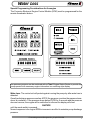
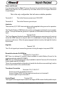
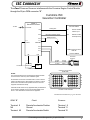
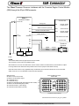
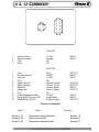
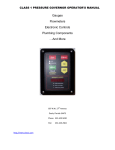
Contents
Pressure Governor for Cummins
“IS” Engines
Contents
Contents ....................................................... 1
Interlocks ...................................................... 2
Overview ...................................................... 3
Operation .................................................. 4-5
Installation .................................................... 6
Water Loss ................................................... 7
Input/Output ................................................ 8
ISC Connector.............................................. 9
ISM Connector ........................................... 10
-4 & -12 Connector..................................... 11
Wiring .................................................... 12-13
Programming ............................................. 14
Notes .......................................................... 15
E:\manuals\governors\ISengines\Gov_IS.p65-07261999
1
Interlocks
Class1 provides a variety of engine controls that are used in a broad range
of applications, therefore it is impossible for Class1 to determine the suitability of a particular control for any specific application. The flexibility of our
products allow them to be used in a limitless number of custom applications.
Class1 can advise you of the features that are available on a given product
so that you can determine what product will meet your needs. We believe
that the Original Equipment Manufacturer’s (OEM) engineering departments
should be qualified experts in their product field and are the authorities on
product application and safety. Since our products are typically used in safety
critical applications, the OEM must undertake appropriate testing to prevent
injury to the end user.
WARNING
!
2
IT IS THE OEM’S RESPONSIBILITY TO DETERMINE THE SUITABILITY
OF ANY PRODUCT FOR AN INTENDED APPLICATION, AND TO INSURE THAT IT IS INSTALLED AND GUARDED IN ACCORDANCE WITH
ALL APPLICABLE FEDERAL, STATE, LOCAL AND NFPA SAFETY AND
HEALTH REGULATIONS, CODES AND STANDARDS.
E:\manuals\governors\ISengines\Gov_IS.p65-07261999
Overview
Electronic Engine Pressure Governor
The Class1 Pressure Governor is designed to maintain a selected pump pressure or engine
speed setting. This unit will work with electronically controlled Cummins Interact System Engines (ISB, ISC & ISM)
Included in the package The governor control is shipped with the following components:
Governor Control
Pressure Transducer
User Manual
Installation Harness
PN
PN
PN
PN
102308
100581/P165-5276-300
102947
102946
Modes of Operation
Power On When the unit is initially powered up, the display will show [MODE] and the
engine will remain at idle. All switches except the MODE switch are inactive at this point. The
mode switch must be pressed to select the desired operating mode (Pressure or Throttle).
Then the INC (increase), DEC (decrease) and PRESET switches become active.
Throttle Mode
When the unit is in RPM mode, the display will read “THROTTLE” and
the green RPM LED will be illuminated. Engine speed is controlled by the increase and
decrease switches, the display will indicate “INCREASE” or “DECREASE” as appropriate
when these switches are depressed. Initially, the engine speed will ramp slowly and then
ramp faster if the switch is held down for more than 3 seconds. The governor will maintain the
last speed attained with these switches.
PSI Mode
When the unit is operating in PSI mode, “PRESSURE” will be displayed and
the amber PRESSURE LED will be illuminated. A pump pressure setpoint is taken from the
pressure transducer each time a switch is pressed. Using the increase and decrease switches,
the display will indicate “INCREASE” or “DECREASE” as appropriate. The governor maintains pump discharge pressure by controlling engine speed to maintain the pressure setpoint.
The governor will maintain the last pressure achieved with the switches. When the governor
is actively controlling the engine to maintain pressure, the display will show “CTRL INC” or
“CTRL DEC” to indicate control and direction.
Switching between modes
Pressing the mode switch will change the governor from
RPM to PRESSURE mode without a significant change in engine speed or pump pressure.
The message center will indicate “PRESSURE” or “THROTTLE” accordingly.
Preset Mode
Pressing the PRESET switch in either mode will control the engine to
attain the preset RPM or pump pressure.
High Idle Mode
An input is available to bring the engine speed to the PRESET RPM
(High Idle) from a remotely mounted switch. When the governor is operating in this mode, the
display will read “HIGHIDLE”. This function is unavailable when the governor is operating or
if the pump is engaged. Pressing the IDLE switch causes the high idle to drop out and the
high idle input must be toggled off and then on again to reinstate high idle. The INC and DEC
switches are active with high idle, however they will not change the stored preset RPM.
Idle Mode Pressing the IDLE switch at any time will return the engine to idle speed and
clear the current session setpoints from the governor.
E:\manuals\governors\ISengines\Gov_IS.p65-07261999
3
Operation
At governor power on, the Message Center will display
[MODE]
and neither the RPM nor the PRESSURE LED will be illuminated.
At this point, you must select an operating mode using the MODE switch before the
governor will operate.
The governor will check for a valid pressure transducer signal at power up, if none is
found
SENSOR
will be displayed in the message center.
If no interlocks are established,
NO-INTLK
will be displayed in the message center when the MODE switch is pressed and the
governor will not respond to an increase or decrease request.
If only the OEM throttle interlock is active, you may select RPM mode and
THROTTLE
will be displayed. If you attempt to select pressure mode,
NO-INTLK
will be displayed when the MODE switch is pressed and the governor will remain in RPM
mode and
THROTTLE
will be displayed. The governor will respond to increase and decrease commands from
the INC and DEC switches within the operating capabilities of the engine. When the INC
switch is pressed,
INCREASE
is displayed in the message center.
When the DEC switch is pressed,
DECREASE
is displayed.
Every time the INC or DEC switch is released, the current engine RPM is maintained by
the governor and the message center will display
THROTTLE
to indicate that the governor is active and operating in RPM mode. Whenever the governor adjusts the engine speed to maintain the established RPM,
CTRL INC or CTRL DEC
will be displayed while the governor is actively adjusting engine speed to maintain the
setpoint. The message center will again display
THROTTLE
once the adjustment has been completed.
When the PTO Engaged Interlock is active, pressure mode can be selected and the
governor switch operation and display is identical to RPM mode except that
PRESSURE
is displayed instead of THROTTLE and the PRESSURE LED will be illuminated.
4
E:\manuals\governors\ISengines\Gov_IS.p65-07261999
Operation
Whenever you desire to return to idle, press the IDLE switch. The message center will
display
IDLE REQ
and the engine speed will be reduced to normal idle. This clears the governor of any
current session PSI or RPM setpoints and
[MODE]
will be displayed in the message center.
The PRESET switch can be used anytime after an operating mode has been selected to
promptly bring the engine or pump to the preset point. The message center will display
-PRESETwhile the engine is being adjusted and then either
THROTTLE
or
PRESSURE
will be displayed dependent on the operating mode selected.
While the governor is powered up and the OEM Throttle Interlock is active, a remote
High Idle function is available. A 12 volt input is available to activate this feature.
This feature will not activate if a governing mode has been chosen, the pump engaged
interlock is active or the throttle interlock is lost. If High Idle is active, it will drop out
when the pump is engaged or the throttle interlock is lost. While the high idle feature is
active,
HIGHIDLE
will be displayed in the message center. The INC and DEC switches are active in the
High Idle Mode, but only change the engine speed from the preset speed for the current
session.
When operating in pressure mode, once the pump pressure exceeds 40 PSI, the governor will monitor the pump discharge for water starvation. If the pump discharge pressure drops below 25 PSI for more than 5 seconds, the governor will return the engine to
idle.
CAVITATE
will be displayed in the message center. The governor enters it’s initial power on state
and a mode must be selected before governing is enabled again.
NOTE:
While the governor is determining cavitation, the discharge pressure
drop will be treated normally. That is, the engine will be commanded to increase speed to compensate for the pressure reduction. This can result in
the engine running at it’s maximum PTO speed. If the water loss is not sufficient to keep the pressure below 25 PSI for 5 seconds, the timing loop is
reentered and this could result in the engine running at maximum RPM for a
period of time longer than 5 seconds. The pump operator should be vigilant
to this possibility.
E:\manuals\governors\ISengines\Gov_IS.p65-07261999
5
Installation
Installation
Control Module
The control module requires a rectangular cutout as shown. The module is
watertight and may be mounted in any location on the operators panel.
4.437
3.687
MOUNTING HOLES AND
6.000
5.250
CUT-OUT DIMENSIONS
3.618
5.180
.201
Pressure Transducer
Locate the pressure transducer in the discharge manifold of the pump. Threads are
1/4 NPT and a sealant should be applied prior to installation. The transducer should be located in an
area with minimum turbulence. When tightening the transducer, apply torque to the 1-1/4” hex flange of
the transducer, not the body.
System Wiring
The pressure governor comes with wiring and connectors to aid installation.
Refer to the diagrams in the manual for specific governor requirements.
Refer to the appropriate Engine Electronic Application and Installation Guide for information on engine
electrical interfacing and programming.
6
E:\manuals\governors\ISengines\Gov_IS.p65-07261999
Water Loss
Special Programming Considerations for the engine
The Cummins Electronic Engine Control Module (ECM) must be programmed for the
remote Accelerator feature.
The pressure governor can be combined with a Class1 Engine Status Center to provide the
pump operator with necessary engine information in a matching style display.
Water Loss The control unit will protect against running the pump dry after water loss is
detected.
Once the discharge pressure reaches 40 PSI, the governor monitors the pressure transducer for cavitation. If the pressure drops below 25 PSI for 5 seconds and the pressure
does not recover, the engine will be controlled to idle and the display will show
CAVITATE
until the mode switch is pressed.
Normal response is for engine RPM to increase in an effort to maintain pump discharge
pressure.
E:\manuals\governors\ISengines\Gov_IS.p65-07261999
7
Input/Output
Power and Ground
It is imperative that the Class1 Pressure Governor be grounded directly to the vehicle
battery and that the unit be powered by the same source as the engine Electronic
Control Module.
This is the only configuration that will assure reliable operation.
Terminal 4-1
This is the Governor power input 12/24 VDC.
Terminal 4-2
This is the Governor ground input.
Interlocks
There are two (2) 12 VDC interlocks that must be supplied to the governor for operation.
Terminal 12-2
The Throttle Ready or OEM Interlock must be continuously maintained once it is established. This input allows the governor to operate in RPM mode and accept a High Idle
input.
Terminal 12-10
The Pump Engaged Interlock is necessary to initiate pressure governing and it must not
cause the OEM interlock to dropout when it is established or erratic operation of the
governor could ensue. When the pump engaged interlock is active, the high idle function
is precluded.
High Idle
Terminal 12-3
This 12 volt signal input causes the governor to bring the engine to a preset RPM.
Remote Accelerator On/Off Relay
Terminals 12-11 and 12-12
ISC There is a delayed (2 second) output available to switch Battery Ground to the
remote accelerator switch (ECM-B45).
ISM There is a delayed (2 second) output available to switch Common #1 to the remote
throttle enable switch (ECM-B43).
This is the recommended configuration to handle the throttle source switching function
from the cab throttle to the remote throttle.
Transducer Connection
Terminals 12-5, 12-6 & 12-7
Sensor ground is provided at terminal 5.
Sensor voltage (5VDC) for the pressure transducer is at terminal 6.
Sensor signal is input at terminal 7.
Control Signal
Terminal 12-8
The engine control signal output is sent to the engine ECM remote throttle position input.
8
E:\manuals\governors\ISengines\Gov_IS.p65-07261999
ISC Connector
The Class1 Pressure Governor interfaces with the Cummins Engine Control Module
through the 50 pin OEM connector “B”.
Cummins ISC
Governor Controller
Class 1
Governor Control
12 VDC
Cummins ISB/ISC
B-3 HI Idle
Analog OUT
B-8
B12
Remote Accelerator Switch
B11
A-1
12 VDC
B9
Remote Throttle
Position Input
B45
Remote Throttle
On/Off (Ground)
Battery Ground
A-2
GROUND
B-5
B-6
OEM Harness Connector
ECM "B"
B-7
B2
Cummins ISB/ISC
B10
Transducer
Connector
A Black
B Red
C White
12 VDC
THROTTLE
Ground
+5 VDC
Signal
PUMP
OEM Interlocks
Cummins "B" Connector
ECM SIDE
NOTES:
The Cummins ECM must be programmed for Remote Throttle!
This document is meant only as an installation guide.
All information is correct as of the date drawn, but the customer
needs to be aware that any documentation is subject to change
without notice and that the best possible resource is from the
equipment manufacturer directly.
01
10
11
20
21
30
31
40
41
50
Interlocks should conform to any applicable safety considerations
for the vehicle's intended use, such as the latest edition of the
N.F.P.A. 1901 Standard for Automotive Fire Apparatus.
Forward or Left Connector
manuals\Governor\Cummins\cum_isc_guv.ai..05211999
OEM- “B”
Terminal 9
NA
Terminal 45
Circuit
Remote Accelerator Position
Ground
Remote Accelerator Switch
Governor
Terminal 8
Terminal 11
Terminal 12
E:\manuals\governors\ISengines\Gov_IS.p65-07261999
9
ISM Connector
The Class1 Pressure Governor interfaces with the Cummins Engine Control Module
(ISM) through the 50 pin OEM connector.
Class 1
Governor Control
Cummins ISM
B-3 HI Idle
Analog OUT
B-8
Switch Common #1 (Ground)
B11
B12
A-1
12 VDC
Remote Accelerator Switch
A-2
GROUND
B21
Remote Throttle
Position Input
B09
Switch Common
B-43
Remote Throttle
ON/OFF (GND)
Battery Ground
OEM Harness Connector
B-5
Cummins ISM
B-6
Transducer
Connector
B-7
12 VDC
B2
B10
THROTTLE
PUMP
A Black
B Red
C White
Ground
+5 VDC
Signal
OEM Interlocks
NOTES:
The Cummins ECM must be programmed for Remote Throttle!
This document is meant only as an installation guide.
All information is correct as of the date drawn, but the customer needs to be aware that any documentation is subject
to change without notice and that the best possible resource is the equipment manufacturer directly.
Interlocks should conform to any applicable safety considerations for the vehicle's intended use, such as the latest
edition of the N.F.P.A. 1901 Standard for Automotive Fire Apparatus.
OEM Connector
09 Switch Common #1 (Ground)
21 Remote Throttle Position Signal
26 J1708 Data Link (+)
27 J1708 Data Link (-)
34 Remote PTO Enable Signal (Preset Speed, NOT Throttle)
43 Remote Throttle Enable Signal (Throttle)
48 Accelerator Position +5 VDC Supply
49 Accelerator Position Return (Ground)
Cummins OEM Connector
ECM SIDE
10
01
20
11
30
21
40
31
50
01
Forward or Left Connector
manuals\Govern97\Cummins\cum_ISM_guv.ai_08232K
10
E:\manuals\governors\ISengines\Gov_IS.p65-07261999
41
7
8
9
11 10
12
4
3
2
4
1
1
3
2
5
6
-4 & -12 Connector
DT06-4S
1
2
3
4
System Power
System Ground
Plug
Plug
12 VDC
Ground
NC
NC
INPUT
INPUT
DT06-12S
1
2
3
4
5
6
7
8
9
10
11
12
Plug
Throttle Interlock
High Idle
Plug
Signal Ground
Signal Voltage
Signal IN
Analog Out
Plug
Pump Engaged Interlock
Delay Relay Common (30)
Delay Relay NO (87)
Plug
12VDC
12 VDC
NC
XDucer Ground
XDucer 5 VDC
Xducer Signal
Control Signal
NC
12 VDC
Enable Input
Enable Output
OUTPUT
INPUT
INPUT
OUTPUT
OUTPUT
INPUT
OUTPUT
INPUT
INPUT
OUTPUT
Governor Connectors
OEM
Terminal 21
Terminal 09
Terminal 43
Circuit
Remote Accelerator Position
Switch Common #1
Remote Accelerator Switch
Governor
Terminal 8
Terminal 11
Terminal 12
E:\manuals\governors\ISengines\Gov_IS.p65-07261999
11
DT06-4S
Sockets
Position
1
2
3
4
Wire Color
RED
Black
Plug
Plug
Connector
Terminal
DT06-12S
Sockets
Position
1
2
3
4
5
6
7
8
9
10
11
12
Wire Color
Plug
Description
+ 12 VDC
Ground
NC
NC
ECU Power
Control Signal
C12- 8
9 Remote Accel Position (ISC)
21 Remote Accel Position (ISM)
Delay Rly 30
C12-11
9 Switch Common #1 (ISM)
Delay Rly 87
C12-12
45 Remote Throttle ON/OFF (ISC)
43 Remote Throttle ON/OFF (ISM)
4-2 Ground
Plug
Plug
Description
NC
OEM Interlock
High Idle
NC
Sensor Ground
Sensor Voltage
Sensor Signal
Control Signal
NC
PTO Interlock
Enable Input
Enable Output
OEM
Interlocks
4-1 12 VDC
High Idle Switch
FAST
IDLE
High Idle C12-3
Throttle
Ready
Throttle Ready C12-2
Pump Engaged C12-10
Sensor Ground C12-5
Sensor Voltage C12-6
Sensor Signal C12-7
manuals\govern97\cummins\ISXwire.ai_05211999
Pump
Engaged
A Black
B Red
C White
12 VDC
E:\manuals\governors\ISengines\Gov_IS.p65-07261999
Connector
Terminal
Cummins
ECM
Ground
+5 VDC
Signal
Transducer
Connector
12
Wiring
Pressure Governor
CONNECTOR: DEUTSCH
DT06-4S
POS WIRE DESCRIPTION
1
RED
(12 VDC)
2
BLACK (GROUND)
3
PLUG
4
PLUG
Wiring
Power Cable
E:\manuals\governors\ISengines\Gov_IS.p65-07261999
CONNECTOR: DEUTSCH
DT06-12SA
POS
1
2
3
4
5
6
7
8
9
10
11
12
WIRE DESCRIPTION
PLUG
OEM INTERLOICK 12V
HIGH IDLE 12V
PLUG
BLACK (TRANSDUCER ground)
RED (TRANSDUCER power)
WHITE (TRANSDUCER signal)
BLACK (ENGINE SIGNAL)
PLUG
PTO INTERLOCK 12V
RED (Ground, chassis or signal)
WHITE (REMOTE ACCEL SWITCH)
CONN: PACKARD 12065287
POS WIRE DESCRIPTION
SENSOR RETURN (BLK)
A
SENSOR +5 (RED)
B
PSG PUMP PSI (GRN)
C
Transducer Cable
Engine Cable
OEM Cable
13
c:\manuals\govern97\CUMG_hrn.ai
THROTTLE SIGNAL
Ground
REMOTE ACCEL SW
CIRCUIT
OEM INTERLOCK
HIGH IDLE
PTO INTERLOCK
COLOR
WHT
WHT
WHT
Programming
Changing the preset RPM or Pressure
Remove power to the controller.
Press and hold the Preset Switch.
Apply power to the controller and continue to hold the preset switch until the display shows
PRESET, then release the preset switch (approx. 5 seconds).
Select a mode and operate the controller until you attain the desired RPM or pressure.
Press the PRESET switch to store this value.
The display will read “STORE” while the value is being stored, change the operating mode
and select the desired preset for that mode.
Press the PRESET switch to store this value.
Press IDLE to return to normal operation.
Programmable Parameters
Press and hold the IDLE and PRESET switches then press the MODE switch. The message
center will show
-MENUpress the MODE switch. This will scroll through the three menu options.
SET RAMP
SET SENS
SET GAIN
When the option that you want to change is displayed, press the INC switch to select it.
RPM Ramp Rate: This parameter controls how fast the governor responds to increase
and decrease requests. Values are 0-10 with 5 being the default. The lower the value, the
faster the response.
Ramp XX
is displayed where XX is the current numeric value. Pressing the INC/DEC switches change
the value. Press PRESET to save change. Press MODE to scroll to the next parameter.
PSI Gain:
This parameter controls the pressure gain or how quickly the governor
controls the engine to react to pressure changes. Values are 0-10 with 5 being the default.
The lower the value, the slower the response.
Gain XX
is displayed where XX is the current numeric value. Pressing the INC/DEC switches change
the value. Press PRESET to save change. Press MODE to scroll to the next parameter.
PSI Sensitivity:
This parameter controls the pressure sensitivity or how much the
pressure is allowed to deviate from the setpoint before the governor will control the engine to
restore the setpoint pressure. Values are 0-10 with 5 being the default. The lower the value,
the tighter the pressure window the governor maintains.
Sense XX
is displayed where XX is the current numeric value. Pressing the INC/DEC switches change
the value. Press PRESET to save change. Press MODE to scroll to the next parameter.
Pressing IDLE exits from the Menu and saves the current parameters. The message displayed is:
-DONE-
14
E:\manuals\governors\ISengines\Gov_IS.p65-07261999
Notes
The control signal is an analog voltage that uses 900 mV for idle and 3.8 V for maximum throttle.
If the signal is present and varies with the INC/DEC switches, it is functioning.
A delay relay is incorporated that activates 2 seconds after 12 V is input on terminal 2 of the 12 pin
connector. Common (30) at pin 11 and NO (87) at pin 12.
12 V at pin 2 allows throttle operation and 12 V at pins 2 and 10 allows PSI governing.
100581
P165-5276
300 PSI
The transducer must have 5 VDC from the governor (B-6) at terminal B.
The transducer must have ground from the governor (B-5) at terminal A.
The transducer returns a variable voltage signal from terminal C to the governor (B-7).
Check for signal voltage and ground at the transducer with a meter between pins A and
B with the transducer unplugged. It must be +5.0 VDC. If the voltage and ground are
correct, plug the transducer in and check for PSI voltage at the governor (B-7). It must
range between 700 mV and 4.5 V and vary with pressure.
91
92
93
94
95
96
True
Pressure
Transducer
Voltage
Low mV
0-22
680
23-34
988
35-44
1168
45-54
1307
55-64
1427
65-74
1567
75-84
1708
85-94
1846
95-104
1988
105-114
2105
115-124
2243
125-134
2384
135-144
2522
145-154
2664
PWM
RAW XDCR
PSI
POT CNTS
PARAMETER
PRESET
E:\manuals\governors\ISengines\Gov_IS.p65-07261999
15