1
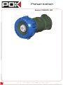
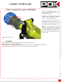
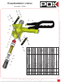
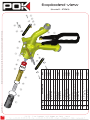
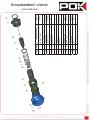
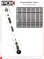
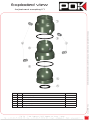
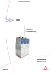
User manual
IPOK & IPOK-S PN40
Doc 1858 EN - Rev. C
Identification
Information contained in this document may vary from the product you received, contact our sales department if necessary.
Subject
Value
Product type
Nozzle
Product
IPOK, IPOK-S, POKINOR 150, Magilite PN40
References
Body : 28123, 28272, 28276
Nozzle : 30495, 28286
Document #
1858
Language
English
Creation date
26/06/2012
Modification date
04/07/2012
Rev. A :
• Original file
Modification follow up
Rev. B :
• Correction of GPM Flow rate
• Nozzle POKINOR 150 added
Doc 1858 EN - Rev. C
Rev. C :
• IPOK/IPOK-S + POKINOR 150 EN15182 datasheet
added
• IPOK/IPOK-S + Magilite PN40 EN15182 datasheet
added
1
Warning
• Introduction
Please read this manual before using the product.
Use, maintenance or any operation have to be made only by persons aware of the security rules and trained
for the use of this equipment.
Please respects the hydraulic characteristics, going over may be dangerous at use, or offer bad performances.
• Dismantling and warranty
Information contained in this document may vary from the product you received, contact our sales department if necessary.
This equipment has a limited warranty of 1 year for any fabrication problem.
Exploded view and bill of materials are not dismantling note.
Do not try to repair or modify the equipment, it may be not working properly and/or dangerous at use.
Dismantling this equipment outside POK factory cancel the warranty.
Do not try to dismantle the Nozzle Magilite PN40, it may require special tools and has to be adjust for flow
rate. If you do not respect this rule your nozzle won’t give the proper flow rate and may have performances
decreased.
If for any reason the equipment is repaired outside POK factory, please order spare parts at POK, otherwise the
characteristics described in this document won’t be valid anymore, and POK responsability void.
Only POK can ensure performances and security folowing to a dismantling. POK SA can’t be responsible of any
damage following dismantling outside its factory.
• Use
Please respect the technical limits of the equipment.
Be careful with the reaction force : from 8 Kg (150 l/min @ 6 bar / 40 GPM @ 90 PSI) up to 22 Kg (150 l/min
@ 40 bar / 40 GPM @ 580 PSI).
It is important to get aware and to respect the security rules in the operating envirronement before using the
equipment.
Do not use the equipment if a part is damaged or missing.
Doc 1858 EN - Rev. C
POK SA can’t be responsible of any accident which occured while using the equipment if the operation and
security rules are not respected.
2
Summarry
Presentation
IPOK + Nozzle Magilite PN40
4
IPOK-S + Nozzle Magilite PN40
4
Nozzle POKINOR 150
5
Characteristics
Information contained in this document may vary from the product you received, contact our sales department if necessary.
General characteristics
6
7-8
IPOK/IPOK-S + Magilite PN40
EN15182 datasheet
9-10
11-12
IPOK
11
IPOK-S
11
POKINOR 150
12
Magilite PN40
12
User manual
13-14
Maintenance
15
Exploded view
Doc 1858 EN - Rev. C
6
IPOK/IPOK-S + POKINOR 150
EN15182 datasheet
Overall dimensions
3
4-5
16-22
IPOK Overview
16
IPOK-S Overview
17
Shutoff IPOK
18
Shutoff IPOK-S
19
POKINOR 150
20
Nozzle Magilite PN40
21
Adjustment coupling
22
Doc 1858 EN - Rev. C
IPOK-S + Nozzle Magilite PN40
Information contained in this document may vary from the product you received, contact our sales department if necessary.
Presentation
IPOK + Nozzle Magilite PN40
4
Doc 1858 EN - Rev. C
Information contained in this document may vary from the product you received, contact our sales department if necessary.
Presentation
Nozzle POKINOR 150
5
Characteristics
Body
• Aluminium alloy
• Coating : yellow polyester painting
Nozzle
• Alluminium alloy
• Coating : OAD or Nituff
Protection sleeve
Thermoresistant polyurethane
Adjustment coupling
• Aluminium alloy
• Coating : OAD or Nituff
Friction parts
• Brass, aluminium
Screws
• Stainless steel
Information contained in this document may vary from the product you received, contact our sales department if necessary.
Construction
Handle characteristics
Inlet
• Female thread 1’’ BSP or 1.5’’ BSP
• Couplings corresponding to your area may be
supplied
Outlet
Male thread 1’’ NST
Working pressure
Up to 40 bar / 580 PSI
Shutoff locking system
Placed on the shutoff handle, lock only the «open»
position
Adjustment coupling angle
• Horizontal : -20° / +20°
• Vertical : -20° / +20°
• Rotating at 360° at the coupling outlet
POKINOR characteristics
Flow rate
Female thread 1’’ NST
Inlet
Female thread 1’’ NST
Flow rate
• 50-75-100 l/min / 13-20-25
GPM (standard)
• Flow adjustment ring adaptable
on demand
• Flow rate up to 150 l/min (40
GPM)
• 6 bar
Up to 250 l/min / 65 GPM
• 40 bar
Up to 150 l/min / 40 GPM
6 to 40 bar (90 to 580 PSI)
6 to 40 bar (90 to 580 PSI)
Standard : 6 bar or 40 bar
Working pressure
Jet
Flush position
Note : flow and pressure
adjustments have to be made
in factory, the product will only
be efficient at the requested
working pressure.
From «straight» to «spread»
(110°) without indexing system
Yes
Standard : 40 bar
Working pressure
Note : flow and pressure
adjustments have to be made
in factory, the product will only
be efficient at the requested
working pressure.
Jet
• Straight
• Attack (30°)
• Spread (130°)
Flush position
Yes
Doc 1858 EN - Rev. C
Inlet
Magilite PN40 characteristics
6
Characteristics
EN 15182 datasheet
IPOK/IPOK-S + POKINOR 150
/!\ DOES NOT COMPLY WITH EN15182 /!\
Doc 1858 EN - Rev. C
Information contained in this document may vary from the product you received, contact our sales department if necessary.
7
• General data
1.1
Manufacturer
1.2
Type
1.3
Type according to EN 15182-1, Annex
A
1.4
Flow rate settings at pR
1.5
Flow adjustments
1.6
Type of spray
• Flow/pressure chart
• Operational devices
POK
IPOK/IPOK-S + POKINOR 150
-
150 l/min @ 40 bar
-
Full cone spray
3.1
Fitting system
Swivelling
3.2
Gripping device
Pistol grip
3.3
Open / Shut-off device
3.4
Jet / spray system
3.5
Flow adjustment system
Trigger
Rotating element
-
Characteristics
EN 15182 datasheet
• Requirements
Item
-2 / § 4.2.1
Dimensions (mm)
-2 / § 4.2.1
Mass (kg)
-2 / § 4.2.2.1
Torques needed for moving operating elements (N.m)
-2 / § 4.2.2.1
Lever
-2 / § 4.2.2.1
Trigger
Test result
376x305x80
2.7
12
-2 / § 4.2.2.1
Flow adjustment element
-
-2 / § 4.2.2.1
Jet adjustment element
3
-2 / § 4.2.2.1
Rotating inlet element
2
-2 / § 4.2.3
Flow adjustment
Rotation from minimal to maximal flow
-
-2 / § 4.2.4
Jet adjustment
Rotation from straight jet to wide spray jet
-2 / § 4.3.3
Effective throw (m)
Information contained in this document may vary from the product you received, contact our sales department if necessary.
PHYSICS
PEROFRMANCE
OPERATING AND HANDLING
Number of
the relevant
subclause of
this part of this
standard
155°
25
Spray jet
-2 / § 4.3.4
Wide spray jet : angle
110°
-2 / § 4.3.5
Narrow spray jet : angle
35°
-1 / § 7.2.2
Sensitivity to frost (°C)
-17°
-1 / § 7.2.1
Sensitivity to heat (°C)
+80°
-1 / § 6.3.1
Non-obstruction test (mm)
-2 / § 4.3.1
Burst pressure (bar)
5
>60
Doc 1858 EN - Rev. C
8
Characteristics
EN 15182 datasheet
Doc 1858 EN - Rev. C
Information contained in this document may vary from the product you received, contact our sales department if necessary.
9
• General data
1.1
Manufacturer
1.2
Type
1.3
Type according to EN 15182-4, Annex
A
1.4
Flow rate settings at pR
1.5
Flow adjustments
1.6
Type of spray
• Flow/pressure chart
• Operational devices
POK
IPOK/IPOK-S + Magilite PN40
Type 3
100 l/min @ 40 bar
50-75-100
Full cone spray
3.1
Fitting system
Swivelling
3.2
Gripping device
Pistol grip
3.3
Open / Shut-off device
3.4
Jet / spray system
Rotating element
3.5
Flow adjustment system
Rotating element
Trigger
Characteristics
EN 15182 datasheet
• Requirements
Item
-2 / § 4.2.1
Dimensions (mm)
-2 / § 4.2.1
Mass (kg)
-2 / § 4.2.2.1
Torques needed for moving operating elements (N.m)
-2 / § 4.2.2.1
Lever
-2 / § 4.2.2.1
Trigger
Test result
405x305x78
2.7
12
-2 / § 4.2.2.1
Flow adjustment element
-2 / § 4.2.2.1
Jet adjustment element
3
-2 / § 4.2.2.1
Rotating inlet element
2
-2 / § 4.2.3
Flow adjustment
Rotation from minimal to maximal flow
-2 / § 4.2.4
Jet adjustment
Rotation from straight jet to wide spray jet
-2 / § 4.3.3
Effective throw (m)
4.5
90
150°
25
Spray jet
-2 / § 4.3.4
Wide spray jet : angle
130°
-2 / § 4.3.5
Narrow spray jet : angle
35°
-1 / § 7.2.2
Sensitivity to frost (°C)
-17°
-1 / § 7.2.1
Sensitivity to heat (°C)
+80°
-1 / § 6.3.1
Non-obstruction test (mm)
-2 / § 4.3.1
Burst pressure (bar)
5
>60
Information contained in this document may vary from the product you received, contact our sales department if necessary.
PHYSICS
PEROFRMANCE
OPERATING AND HANDLING
Number of
the relevant
subclause of
this part of this
standard
Doc 1858 EN - Rev. C
10
Doc 1858 EN - Rev. C
Information contained in this document may vary from the product you received, contact our sales department if necessary.
Overall dimensions
11
• IPOK
WEIGHT : 1.9 Kg
• IPOK-S
WEIGHT : 2 Kg
WEIGHT : 0.7 Kg
• Nozzle Magilite PN40
Information contained in this document may vary from the product you received, contact our sales department if necessary.
Doc 1858 EN - Rev. C
Overall dimensions
• Nozzle POKINOR 150
WEIGHT : 0.7 Kg
12
User manual
• Putting the equipment under service
1 - Make sure no part is missing or damage.
2 - Make sure the components move as they should (jet adjustment ring, flow adjustment ring, shutoff handle,
adjustment coupling).
3 - Connect a water way to the shutoff inlet (1’’ or 1,5’’ depending on your model).
4 - Make sure your hose are correctly connected and that there is no hose misplacement.
5 - Put the equipment under water and pressure.
Information contained in this document may vary from the product you received, contact our sales department if necessary.
Note : depending on your pressure of use, special characteristics may be require on your hose. Becarful to the
hose force when it is put under water and pressure.
• How to lock the handle in open position
2
1
While using se the nozzle, you
can lock the handle on the open
position.
1 - Open the shutoff and maintain
it open.
2 - Push the lock button.
3 - Release the shutoff handle,
it should move a bit and then be
blocked.
4 - To unlock simply use the
shutoff handle as if you were
trying to use the open position,
the locking system will be
released.
Using the handle locking system
• How to adjust flow rate and jet angle (Magilite)
Depending on your operating
condition, you may need to
adjust the flow rate and the jet
angle.
On the nozzle just rotate to the
left or to the right the protection
sleeve to adjust the jet angle
from straight to spread (130°).
Doc 1858 EN - Rev. C
To adjust flow rate, rotate the
ring with number written on it
(the closest mark to the handle).
13
Note : If you rotate to the left
too far, you will put the nozzle
in flush position. This position
open the valve at its maximum in
order to evacuate particles stuck
in the nozzle.
Jet adjustment ring
Flow adjustment ring
Adjustments ring
User manual
• How to adjust jet angle (POKINOR)
Withe the POKINOR Nozzle, you
can’t adjust the flow rate, it is
adjusted in factory.
This mean when rotate the jet
adjustment ring, you can let it on
its position without risks, it may
be useful in some conditions.
Jet adjustment ring
Adjustment ring
• Limits
While using the equipment, please respects the following rules :
• Do not target someone with the jet.
• Make sure you’re complying with the security rules in your operating environnement.
• Becarful to the reaction force. (see «warning» for more details).
Doc 1858 EN - Rev. C
Note : If you rotate to the left
too far, you will put the nozzle
in flush position. This position
open the valve at its maximum in
order to evacuate particles stuck
in the nozzle.
Information contained in this document may vary from the product you received, contact our sales department if necessary.
Perhaps you can change the jet
shape, from straight to spread
(110°) without indexing pin.
14
Maintenance
• Cleaning
In order to maintain the equipment working properly it is recommended to do those operations after every
use :
• Rotate the flow adjustment ring to «Flush» and let the nozzle working with clear water. This operation will
clean up inside the nozzle and evacuate the remaining particles. This operation is much more important if you
do not use clear water at use.
Note : Do not use corrosive products, this would damage gaskets with consequences of leackage and
malfunction.
• Make sure no parts are missing or damaged. In this case do everything necessary to replace it as soon as
possible and do not use the nozzle while it’s not repaired.
Note : Under pressure and especially high pressure any missing parts may make the nozzle dangerous at use.
• Make sure every parts move as they should move, the adjustments ring must rotate without be block or hard
to move (an indexing system is present to lock the current position, but nothing should be harder that this
point). The handle should move without particular effort, and the locking system should work properly. The
inlet coupling must move properly in any direction (-20° / +20° and rotate at 360°).
/!\ WARNING /!\
With a nozzle set to work at 40 bar (580 PSI), the valve must not be damaged, pay a special attention to this
while using, cleaning or stocking it. Any damage may change the shape of the jet and have a negative effect
on performances.
• Spare parts
Depending on storage and/or using conditions, some parts may need to be replaced more or less often.Please
contact our sales service in order to obtain information about return, or to receive spare parts.
Use the exploded view and bill of materials to identify the parts.
Doc 1858 EN - Rev. C
Information contained in this document may vary from the product you received, contact our sales department if necessary.
• Clean the exterior of the nozzle with clear water.
15
REP
QTY
1
28
2
1
Gasket R27
3
1
Inlet coupling cap
DESCRIPTION
Doc 1858 EN - Rev. C
Information contained in this document may vary from the product you received, contact our sales department if necessary.
Exploded view
Overview - IPOK
Balls Ø4
REF
00752
16
Doc 1858 EN - Rev. C
Information contained in this document may vary from the product you received, contact our sales department if necessary.
Exploded view
Overview - IPOKS
17
REP
QTY
1
28
2
1
Gasket R27
3
1
Inlet coupling cap
Balls Ø4
DESCRIPTION
REF
00752
1
2
2
2
1
16
17
18
19
Doc 1858 EN - Rev. C
1
15
1
9
14
2
8
19
1
7
13
1
6
1
6
5
12
6
4
1
1
3
1
1
2
10
1
1
11
QTY
REP
DESCRIPTION
Locking system
REF
28283
28089
28095
28094
20277
29253
29252
28090
29669
28093
28088
28128
Information contained in this document may vary from the product you received, contact our sales department if necessary.
Washer M10 - Ø10,5 x Ø18 x
1,6 - DIN 433
Rod
Friction ring
Drive axis
Screw STHC PL M8 - 6
Ball Ø6,35
Spring
Press for gasket
Closing gasket
Plunger
Gasket R19
Sheathing
Gasket R21
Screw CBHC M6 - 20
Washer M6
Handle axis
Handle
Body
Exploded view
Shutoff - IPOK
18
19
2
1
1
8
9
10
1
2
2
2
1
15
16
17
18
19
1
1
7
14
1
6
19
6
5
13
6
4
1
1
3
1
1
2
11
1
1
12
QTY
REP
Doc 1858 EN - Rev. C
Locking system
Washer M10 - Ø10,5 x Ø18 x
1,6 - DIN 433
Rod
Friction ring
Drive axis
Screw STHC PL M8 - 6
Ball Ø6,35
Spring
Press for gasket
Closing gasket
Plunger
Gasket R19
Sheathing
Gasket R21
Screw CBHC M6 - 20
Washer M6
Handle axis
Handle
Body
DESCRIPTION
28283
28089
28095
28094
20277
29253
29252
28090
29669
28093
28088
28086
REF
Information contained in this document may vary from the product you received, contact our sales department if necessary.
Exploded view
Shutoff - IPOKS
Doc 1858 EN - Rev. C
1
1
1
1
1
1
1
1
1
3
1
1
1
1
1
1
1
2
3
4
5
6
7
8
9
10
11
12
13
14
15
16
Nut HM M4
Valve
Valve axis
Protection sleeve
Head ring
Guiding ring
Ball Ø4
Sleeve
Gasket R15
Bore
Gasket R20
Flush spring
Centering ring
Cross-piece
Flat gasket 1’’ NST
Inlet coupling female
thread 1’’ NST
DESCRIPTION
Information contained in this document may vary from the product you received, contact our sales department if necessary.
QTY
REP
8009
19331
23999
28061
8012
11507
8004
8017
11508
19331
10838
REF
Exploded view
POKINOR 150
20
Doc 1858 EN - Rev. C
21
1
11
1
1
1
22
30
19
20
1
18
21
1
1
16
17
1
1
15
2
9
10
1
2
8
14
2
7
1
1
6
1
1
5
12
Ball Ø6,35
1
4
13
Spring
1
3
Flat gasket 1’’ NST
Screw STHC PL M6-10
Swivel female thread 1’’ NST
Ball Ø4
Centering cross-pieces
Nut H M4
Valve
Cap nut
Valve axis
Cross-pieces
Head protection sleeve
Jet guide
Head ring
Cap for ball Ø6,35
Flow guide
Flow adjustment ring
Gasket Ø22 x Ø2
Bore
Gasket Ø30 x Ø2
3
2
Sleeve
1
1
DESCRIPTION
QTY
REP
Information contained in this document may vary from the product you received, contact our sales department if necessary.
12074
24873
8116
23172
23171
23999
23170
30499
8019
27204
23168
30501
23165
30498
REF
Exploded view
Nozzle Magilite PN40
Exploded view
Information contained in this document may vary from the product you received, contact our sales department if necessary.
Adjustment coupling (1’’)
QTY
1
1
Swivel coupling
DESCRIPTION
25559
REF
2
1
Central part
25560
3
2
Gasket Ø47,22 x Ø3,53
4
4
Axis
25558
5
1
Inlet coupling FF 1’’ BSP
28282
6
1
Flat gasket 1’’ BSP
Doc 1858 EN - Rev. C
REP
22