1
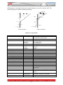
BRG Wireless Analog Time Zone Clock System Installation and Operation Manual BRG Precision Products 600 N. River Derby, Kansas 67037 http://www.DuraTimeClocks.com [email protected] 316-788-2000 Fax: (316) 788-7080 (Patents Pending) Updated: 5/31/2013 Our mission is to offer innovative technology solutions and exceptional service. 1 Table of Contents OVERVIEW ................................................................................................................................................................3 FEATURES AND OPTIONS .....................................................................................................................................4 INSTALLATION.........................................................................................................................................................7 OPERATION.............................................................................................................................................................10 MASTER CLOCK CONFIGURATION MENU....................................................................................................12 ALARM CONFIGURATION ..................................................................................................................................21 ALARM CONFIGURATION WORKSHEET .......................................................................................................25 ETHERNET COMMUNICATIONS .......................................................................................................................26 WIRELESS GPS AND ETHERNET GPS TIME RECEIVERS ..........................................................................32 WARRANTY AGREEMENT ..................................................................................................................................34 INDEX ........................................................................................................................................................................39 2 Overview The BRG wireless clock system is specifically designed for applications where precision and reliability are of great importance. Time updates using the standard Network Time Protocol (NTP) and/or optional Global Positioning Satellites (GPS) provides the master clock(s) with constant time updates. All clocks in the system will not only display the same time, but the true legal time. Any combination of clock shapes, style or size may be synchronized. BRG clocks are designed for organizations that require reliable and accurate synchronized time. The BRG multi-path wireless clock system is highly reliable. The system operates on the license-free 2.4 GHz Industrial, Scientific and Medical band. Spread Spectrum radios are used to enhance signal coverage, along with AES 128 bit encryption to enhance security and reliability. Multi-path wireless communications are used to propagate the time signal throughout any size facility. The failure of any single clock will not affect the remaining clocks in the system. Supervision is available to automatically check the operation of all wireless devices on the system. The system can be configured to use multiple, simultaneous time sources. For example, NTP and GPS time sources can be used at the same time. Multiple master clocks may be used so that if one master clock is down or loses sync, the system automatically continues to function normally from the secondary master clock. BRG digital clocks include an internal Lithium battery that will maintain the time for up to 10 years. BRG battery powered clocks utilize a redundant parallel battery configuration that allows the clock to function even if a battery fails. No other system on the markets offers this level of reliability and ease of operation. Each master clock may be configured for a variety of time zone and Daylight Saving Rules, including UTC (Zulu) Time, Any World Time Zone, Half-hour time zones, Enable or Disable Daylight Saving Time, and selectable 12 or 24 hour display formats with digital intensity control on digital clocks. 3 Features and Options The Wireless Synchronized Time Zone Clock System offers flexibility and reliability for demanding time display applications. This clock system will perform flawlessly for any size facility, or campus. Master Clock Package Contents 1. 2. 3. 4. 5. RC100 Master Clock AC Power Adapter with plugs for North America, UK type, Europe and Australia 10 feet (15M) of Cat-5 network cable Quick Start Guide User Manual Standard Features 1. 2. 3. 4. 5. 6. 7. 8. 9. 10. 11. 12. 13. 14. 15. 16. 17. 100% digital radio communications Simple installation. No system configuration required. Just insert batteries and hang on the wall. Self-healing network Sixteen times the power output of the next competing multi-path clock system Multiple master clock configurations are supported for increased reliability All master and secondary clocks throughout the system are synchronized to the U.S. Atomic Clock. AES 128 bit encryption, providing secure and reliable communications Uses the standard 2.4 GHz ISM (Industrial, Scientific and Medical) band for global compatibility Master clock with LCD display for time and configuration Secondary clocks continue to maintain time in the absence of a time signal. No FCC License or additional government authorization required. Spread Spectrum technology (DSSS), developed for the U.S. Government, is used throughout the system. Electrical and/or network wiring is eliminated when using battery powered wall clocks. Battery powered analog wall clocks will operate five years or longer between battery changes. Daylight Saving rules can be changed at any time. Temperature compensated quartz oscillator Master clock and Digital Clocks include a 10 year lithium battery – uses one millionth of a watt in standby mode 18. Enable/Disable auto switching between daylight and standard time 4 General Specifications: Digital Radios Frequency 2405 to 2480 MHz Protocol 802.15.4, Proprietary Mesh Network Operating Mode ISM Modulation Direct Sequence, Spread Spectrum, Digital Data Speed 250 Kbps Operating Voltage 2.1 to 3.3 Volts Output Power +20 dBm Rx Sensitivity -97 dBm Range 3,000 + feet (900 meters) Operating Temperature -40C to +85C Regulatory Certification FCC-ID W7Z-ZIC2410P2, IC 8254A-ZIC24102, CE Digital Codes Available 65,535 Antenna Type Inverted-F PCB antenna, no external access RF Channels 16 External controls None Rx Current 30 mA Tx Current 200 mA Collision Avoidance Yes Channel Busy Detection Yes 5 RC100 Master Clock Environment: -32 degrees F to 120 degrees F, Humidity: 0% to 95% non-condensing Internal Time Battery Backup: 10 year Lithium Battery Clock Accuracy: The RC100 incorporates an ultra-high precision temperature compensated quartz oscillator. Nominal accuracy provided is + or – two seconds per year at 70 degrees F, correctable to + or – 0.1 second per year using an NTP and/or GPS time source. Construction: ABS plastic cabinet allows the internal antenna to communicate with any number of secondary devices. Power Requirements: 7-12 volts DC, 2 amps AC adapter input 100-240 VAC, 0.8A, 47-63 Hz (FCC, UL, CE CB, GC) RC50 Battery Powered Analog Clock Movement Environment: 32 degrees F to 120 degrees F, Humidity: 0% to 95% non-condensing Clock Accuracy: Nominal accuracy provided is + or – one second when updated seven times per day. Construction: ABS plastic cabinet allows the internal antenna to communicate with any number of secondary devices. Power Requirements: Four LR6 (AA type) Alkaline or Lithium primary batteries 6 Installation Master Clock Installation The master clock must be installed and synchronized with a local or public time server before installing slave clocks. For best results, locate the master clock within 150 feet from the time zone clocks. 1. Connect the network cable into the back of the master clock. 2. Plug the low voltage cable from the AC adapter into the back of the master clock. 3. Plug the AC adapter into a wall outlet. The master clock will attempt to automatically register with the computer network using DHCP. If a network connection is successful, it will then attempt to acquire network time from public time servers using NTP (Network Time Protocol). If DHCP is not available, the master clock’s network interface must be configured with fixed IP address information. If an internal or other time server is to be used in place of public time servers, then this too will need to be changed in the network interface. See the Ethernet Communications section later in the manual for more information about configuring the Ethernet interface. When the master clock receives a time update from the time server, an asterisk (*) will appear in the lower right corner of the LCD display. A “T” will appear on the lower left side of the master clock’s display when it is actively broadcasting time packets. The master clock incorporates a high precision temperature compensated quartz oscillator, so the clock will maintain the time for an extended period without external time updates. An optional GPS receiver is available for the master clock. This receiver sends the time received from the GPS satellites wirelessly to the master clock. The GPS receiver can be used in addition to NTP time for a redundant time source. Connections on the back of the master clock. 7 The RC100 master clock includes connections for power, alarm relay and Ethernet. The alarm relay includes 10 Amp contacts. Larger loads should make use of a slaved relay. Analog Clock Installation The clocks should be brought within 150 feet of the operating master clock. Insert batteries into the clock’s battery holder. The clock will receive a time update from the master clock and move the hands to the configured time zone. Digital Clock Installation If the clock system is comprised entirely of digital clocks, the digital clock will receive and move to the correct time (if it isn’t already there) as soon as power is applied. Wireless Relay / Audio Player / Tone Generator Installation While the master clock includes alarm relay connections, the location of the alarm devices may be some distance from the master clock. In this case, wireless alarm relays are available. Wireless relays should be located within 150 feet of continuously active network transmissions. The wireless relay / tone generator includes a configuration dip switch. Switch position 1 sets the audio output, up=high (1 volt P-P), down=low (0.5 volt P-P). Switch position 2 sets the device function (up=audio player w/ relay following, down=timed relay). Switch positions 3-6 sets the alarm zone number (binary 1-12). Switch positions 7-10 sets the radio channel number (binary 0-15). Setting the channel to 15 will cause the device to transmit and receive on all channels. When switch position 2 is in the up position, the relay will activate as long as audio is playing. When the switch is down position, the relay will use the timed values indicated in the drop down box of the Windows alarm configuration program. In addition to the time relay values, the relay can be configured to remain on or off indefinitely. DIP switch setting (default) for high volume, audio player active, alarm zone 1, radio channel 0 DIP switch setting for audio disabled with timed relay active, alarm zone 1, radio channel 0 8 Binary value DIP switch settings – use the following table to configure the switches for the zone and channel numbers. Disregard the numbers on the switches in the following table. For example, the zone number switches on a wireless relay are numbered 3-6 and the channel switches are numbered 7-10. =0 =4 =8 = 12 =1 =5 =9 = 13 =2 =6 = 10 = 14 =3 =7 = 11 = 15 The relay output of the master clock is always a timed or steady state, and does not follow any audio play, or zones. An internal speaker is available when the device is in audio player mode. The Wireless Relay / Audio Player includes over 70 pre-recorded tones, chimes, buzzers and bells. Also included are various Westminster clock chimes. These chimes can be configured as a campus wide clock chime system. For best results, use only SanDisk brand memory cards. The wireless alarm relay includes 10 Amp contacts. Larger loads should make use of a slaved relay. Wireless Relay modules receive and repeat all radio transmissions to propagate the signal throughout the facility. The wireless control program for Windows is available to configure and control alarm settings. Setting the channel to 15 will cause the device to transmit and receive on all channels. Repeaters and analog clocks always transmit and receive on all channels. 9 Operation The RC100 master clock obtains time updates from local or public time servers, and/or from the optional GPS receiver. The time received is used to update the master clock’s internal temperature compensated quartz oscillator. The internal clock is backed up using a 10 year Lithium battery to prevent time disruptions due to power outages. All master clock configuration parameters are stored in non-volatile memory and are unaffected by power outages. The master clock transmits time updates using a 2.4 GHz Direct Sequence, Spread Spectrum digital radio. All data transmitted is encrypted using AES-128 bit data encryption for security and reliability. The RC100 master clock broadcasts time updates every second (86,400 times per day). The analog clock movement periodically turns on the internal radio transceiver for 5 seconds in preparation for a time update. After which, it places the radio transceiver in sleep mode. In this mode, the transceiver is no longer operational and uses very little power to remain in sleep mode. If the batteries are removed while the transceiver is in sleep mode and immediately inserted, the hands will move to 12:00, but the movement will not receive a time update. This is because the capacitors within the movement keep the transceiver powered enough to remain in sleep mode for several minutes after the batteries have been removed. To reset the transceiver, remove the batteries for at least five minutes. Then insert the batteries. The hands will move to 12:00 and wait for reception. Then the hands will move to the correct time. If the radio transceiver is not reset, it will still receive a time update and move the hands to the correct time; however, it will be some time later. If a battery clock is in low power mode, removing and reinserting the batteries or pressing the receive button will enable reception. Changing batteries in battery powered analog clocks Batteries should be changed as soon as the clock second hand begins double stepping. If all clocks are double stepping, then first check that the transmitter is operational. Remove all batteries, then insert new batteries. All replacement batteries must be new and of the same type. 10 If the clock is displaying the correct time after changing the batteries, but is double stepping the second hand, go ahead and hang it back on the wall. Normal operation of the second hand should start by the next day. Pressing the REC ore Reset buttons should cause the clock to receive a time update. When the master clock receives a time update from a network or GPS time server, a time source indicator with an asterisk (E* or G*) will appear in the lower right corner of the LCD display. E* indicates the last time update received was from a computer network time server. This includes the MCR1000GPS receiver/time server. G* indicates the last update received was from a wireless GPS receiver. Multiple time sources may be used simultaneously. Analog clocks will step the second hand every two seconds if sync is lost for more than a day. On 2.4 GHz devices, channels 0-15 correspond to 802.15.4 channel 11-26. 11 Master Clock Configuration Menu General Menu Navigation: Master Clock configuration is accomplished by editing parameters using a simple menu system. Only four buttons are used to navigate the menu. The Mode button enters the Menu. The Up and Down buttons move up and down through the menu items, and are used to change parameter values. The Timer Control (TC) button is used to save any changes and exit the menu system. Operation – Press and hold the Mode button to access the menu system. The hours and minutes will blink for about ten seconds. When the hours and minutes stop blinking, release the Mode button. A one (1) will appear on the display. This is menu position 1. Using the Up and Down buttons, select the desired menu item. Press the Mode button again to display the parameter. For menu items above 19, press Mode again to access the menu’s second level. When a 1 appears, indicating the second level menu, press the Up or Down buttons to select the desired menu item, then press Mode to display the parameter value. Press the Up or Down buttons to change the parameter value. Once the parameter value is changed, press Mode to back out of the item and move to another item, or press the Timer Control (TC) button to save and exit the menu system. Pressing the Timer Control button at any time will save your changes and exit the menu system. Pressing the Mode button while a parameter value is displayed will back up one level. Press Up or Down to move to the next mode item. Pressing the Down button until mode 0 is reached will exit the menu system. Pressing the Timer Control (TC) button also exits the menu system. The menu will timeout and return to normal operation after 60 seconds in inactivity. First Menu Level Mode Number 0 Second Menu Level N/A Value Range Mode Description and Instructions 00:00 to 23:59 Exit Menu System Simply press the Up button to advance the time, or the Down button to decrement the time. The longer the buttons are held down, the faster the time will change. Pressing the Timer Control button will also exit the menu system. 1 N/A 01/01 to 12/31 Month/Day Pressing the Up button increments the days and months, pressing the Down button decrements the days and months. Incrementing past the end of the year, or decrementing past the beginning of the year, will change the year respectively 2 N/A 1992-2075 6 N/A 1-2 19 N/A 0 00 to 9 99 Year Change using the Up and Down buttons Display Logo Refresh If the LCD display does not have the startup logo, set Mode 6=1. Software Version Number Displays the clock software version number. Press the Mode button to exit or let the 12 First Menu Level Mode Number Second Menu Level Value Range Mode Description and Instructions menu timeout. 21 1 -12 to 12 hours from UTC 23 1 12, 24 Time Zone Offset This value determines the number of hours to add or subtract from Universal Coordinated Time. This parameter is usually only used with time zone clocks or clocks containing an atomic clock receiver. See also Mode 33 for forced half hour and one hour offsets. For accurate time zone information, see http://www.timeanddate.com 12 or 24 hour display format default=12 This mode selects either 12 or 24 hour display format for each four digit display when displaying real time. 24 1 0,10 Daylight Saving Time This mode selects the rules to use when automatically switching between Daylight and Standard time. 0=disable daylight time; 10=rule based switching (default) See also Mode 52 and Mode 45-20, Mode 45-21 27 1-99 alarm setting 00:00 to 23:59 Alarm Set Time Hours / Minutes This mode is used to set the alarm hour and minutes. There are 99 possible settings. Mode 28 optionally sets the seconds. Mode 29 determines the day(s) to activate the alarm(s). A day code must be set to enable alarm. Mode 32-23 enables (default) or disables the alarms. Mode 38 contains alarm schedule assignments. Mode 37-1 determines which schedule is active. Mode 32-16 activates alarms in slave clocks. Mode 49 enables alarm toggle on/off. This overrides momentary alarm activation. Mode 37-2=1 enables snooze function to turn off alarm before the predefined alarm duration has expired. See Mode 34 to activate the alarm at sunrise and/or sunset. See Mode 49 to use the real time alarm settings to control timer functions. See also Modes 28, 29, and 59. In Tiger version 3.75 and later, the number of alarm entries has expanded from 100 to 1000. The 1000 alarm entries are stored in 10 different schedules of 100 entries each. When Mode 37-1=0, alarm schedules will automatically change depending on the active date range. There are 20 date ranges available. The Mode 38 function has changed. It now determines which schedule is active for date ranges defined in Modes 53, 54, 55 and 56. Setting Mode 32-4=4 allows the Timer control button to switch between schedules 0-10 (0 activates date range switching). Press Timer Control to access Mode 37-1. Use the Up and Down buttons to change the schedule from 0-10, then press Timer Control to save and exit. 28 1-99 alarm setting 00 to 59 Alarm Set Time Seconds This mode is used to set the alarm seconds. There are 99 possible settings. Mode 29 determines the day(s) to activate the alarm(s). A day code must be set to enable 13 First Menu Level Mode Number Second Menu Level Value Range Mode Description and Instructions alarm. 29 1-99 alarm setting 0-15 day code Alarm Day Code This mode is used to set the alarm day code. The possible values for each alarm setting are: 0=no alarm, 1=Monday, 2=Tuesday, 3=Wednesday, 4=Thursday, 5=Friday, 6=Saturday, 7=Sunday, 8=Everyday, 9=Weekdays, 10=Sat/Sun, 11=Mon/Wed/Fri, 12=Tue/Thu, 13=Tue-Sat., 14=Mon-Thu, 15=Mon-Sat Display and time source number 1 is used for alarm activation in multi-display clocks. In addition to day-of-the-week combination codes, Mode 29 also accepts any day combination. A value greater than 128 is treated as a binary command. Days of the week are assigned the following binary numbers: Mon=1, Tue=2, Wed=4, Thu=8, Fri=16, Sat=32 and Sun=64. Any combination of days may be selected by adding their assigned numbers together and then adding 128 to that value. For example, if Mon, Wed and Fri are required, then the value would be 149 (1+4+16+128=149). 32 5 0-11 Alarm Zone Address 0-11 , 0=default This value determines the alarm zone of this clock’s relays. 32 42 0-99 Clock Address for PC Control (default=0) If the address value sent equals the value specified in this mode, then the clock will accept the data packet. For PC control, all clocks may be addressed by sending address 0. 32 59 0,1 Accept or Ignore Global PC Commands – 1=accept (default) 0=reject global address PC commands 14 First Menu Level Mode Number Second Menu Level Value Range Mode Description and Instructions PC commands received with an address of 0 will be ignored if Mode 32-59=0. 32 68 0-5 Time Reception Port Control 0=receive time on both ports if configured; otherwise, does not receive remote GPS time packet either over the air or from Ethernet. 2= receive time on GPS port only, does not receive remote GPS time packet either over the air or from Ethernet. 3= do not receive time on any port, does not receive remote GPS time packet either over the air or from Ethernet. 4= receive time on GPS port from a remote GPS receiver over the air. 5= receive time on SRST port from a remote GPS receiver using the Ethernet cable (SRST port). NTP time and other standard time packets will be ignored. 6= (default) receive standard time packets (NTP) over the Ethernet port and time packets over the air from a remote GPS receiver. This configuration provides a redundant time source. If one of the time sources provides incorrect time, the master and slave clocks may jump periodically between the two times. This configuration does not affect the reception of commands, only the reception of time broadcasts. 32 73 0,1 Time Transmission Period Control 0= transmit time once per second 1= transmit when second unit equals 1, 4 or 7 2= transmit on the even second (default) This mode configures the time packet transmission rate as indicated above. 33 1 0-5 code Force Time Advance This mode optionally forces a 30 to 60 minute time advance. 0= no advance (default), 1=30 minute advance, 2=60 minute advance, 3=30 minute advance during daylight saving time only, 4=60 minute advance during daylight saving time only, 5=45 minute advance. This is used in areas that have a 30 to 60 minute advance over the area time zone. For example, Mumbai, India’s time zone offset is +5:30. To configure the time zone, first set the zone to +5 hours using Mode 21-1. Then set Mode 33-1 to 1. 37 1 1-99 Active Alarm Schedule (default=1) This parameter determines which (1-98) alarm schedules is active. Setting Mode 37-1=0 will cause the date ranges to be used. Use Mode 53,54,55 and 56 to change date ranges. Alarm group 1 is different than the other 19 alarm groups. If no date range is active, then group is 1 the default. This feature reduces the number of alarm entries required in some schedule situations. See also Mode 38 – 15 First Menu Level Mode Number Second Menu Level Value Range Mode Description and Instructions Alarm Schedule Group Assignment. A value of 99 in mode 38 will cause the alarm to activate in all schedules if the day code matches the current day. The 1000 alarm entries are stored in 10 different schedules of 100 entries each. When Mode 37-1=0, alarm schedules will automatically change depending on the active date range. There are 20 date ranges available. The Mode 38 function has changed. It now determines which schedule is active for date ranges defined in Modes 53, 54, 55 and 56. Setting Mode 32-4=4 allows the Timer control button to switch between schedules 0-10 (0 activates date range switching). Press Timer Control to access Mode 37-1. Use the Up and Down buttons to change the schedule from 0-10, then press Timer Control to save and exit. 37 2 0-2 Manual Alarm Button This Mode applies to the master clock relay only. When this Mode is enabled, alarm schedule switching using the Timer Control (TC) button is disabled. 0=not active (default), 1=code blue line toggles alert horn on and off. Mode 45-19 optionally determines the number of seconds the alarm will sound before automatically turning off. If the timeout value is 0, the alarm will sound until the code blue line is momentarily closed. This setting will also cause the timer control button to act as a snooze button, turning off the alarm before the alarm period has expired. 2=alert horn will sound as long as code blue line is closed. The Panic Alarm function overrides all other timer control functions. This mode may used with real time alarms to turn off the alarm before the predefined alarm duration expires. 37 10 0-18 Analog Clock Time Zone Position Number 0 = disabled 1-18 = enabled This mode is used to configure the zone position number of analog clocks used in a time zone display. This number is the sequence of available clock zones. It is not the offset from UTC. More than one clock may use the same zone number if the offset from UTC are to be the same. Set Mode 37-10 to the desired zone number 1-18. The master clock will then begin broadcasting on this zone, plus flag instructing the analog clock to save the zone number. Once the master clock is broadcasting the time zone command, remove and reinsert the analog clock’s batteries. The hands will begin to move. Once they stop, set mode 27-10 back to 0. To configure another clock, repeat the process. The zone position number will appear in the upper right corner of the master clock while the time zone position command is active. This feature is available in RC100TZ version 4.87 and later. 37 33 0-99 Radio Power On Period 0=5 sec (default) 1-99 = seconds to power the radio This mode determines how long the battery powered radio in analog clocks will 16 First Menu Level Mode Number Second Menu Level Value Range Mode Description and Instructions remain on before going to sleep mode. By default, the mode is set to zero which flags the radio to remain powered for 5 seconds. This allows enough time to obtain a time update and repeat five time update packets, while maximizing battery life. However, it is too little time to gain control over the air to reprogram the device. If the radio needs to be reprogrammed over the air, set Mode 37-33=30. This will keep the radio powered for 30 seconds which should be enough time to reprogram the radio. Once programming is complete, return Mode 37=33 to 0 to maximize battery life in the analog clocks. This mode requires RC100 Tiger version 1.20 or later and analog clock radio firmware version 1.8 or later. 37 65 0-99 Wireless/Ethernet Sync Indicator Delay 5= (default) This value determines the number of minutes between a change in sync status and resetting the sync status indicator. 37 77 0-10 RC60 Analog Clock Movement Second Motor Control (not used with analog time zone displays) This mode conserves power in battery powered model RC60 analog clock movements by turning off the second hand motor at times when it is not needed. The second hand motor operation can be reduced up to 500 million motor pulses over a five year period. This not only conserves battery power, but also prolongs the life of the movement. Modes 37-78 and 37-79 determine the hour to turn the second motor on and off. 0 - second motor always on 1 – turn off second motor Monday only 2 – turn off second motor Tuesday only 3 – turn off second motor Wednesday only 4 – turn off second motor Thursday only 5 – turn off second motor Friday only 6 – turn off second motor Saturday only 7 – turn off second motor Sunday only 8 - turn second motor off all day Sunday plus designated hours other days 9 - (default) turn second motor off all day Saturday and Sunday plus designated hours other days 10 – Everyday using designated hours 37 78 0-23 Number of Analog Clock Time Zones in an Analog Time Zone Display 1-18 8=default This mode determines the number of time zones in an analog time zone display. Mode 18 should be set to the same value. 37 81 1-8 45 20 111 – 3231 Alarm Duplicate Packets 1-8, 2=default Wireless alarms are now sent multiple times 300 ms apart. Mode 37-81 (default=3) determines the number of times to send the alarm command. Daylight Saving Rule – Start DST Default=327 – (Second Sunday in March) 17 First Menu Level Mode Number Second Menu Level Value Range Mode Description and Instructions The format is MMRD, where MM = month (1-12), R = instance of the select day of the week (1-5 5=last instance), D = day of the week (1-7), where 1=Monday and 7=Sunday. For example, 357 = the last Sunday in March, or 1117 = the First Sunday in November. If the value >2000 then the right two digits represent the day of the month. The left two digits, minus 20, equal the month. For example, March 15th = 2315, April 1st = 2401. The day of the year derived from this rule is stored in Mode 52-1. See also Mode 45-21, Mode 45-22 and Mode 45-23. 45 21 111 – 3231 Daylight Saving Rule – End DST Default=1117 – (First Sunday in November) The format is MMRD, where MM = month (1-12), R = instance of the select day of the week (1-5 5=last instance), D = day of the week (1-7), where 1=Monday and 7=Sunday. For example, 357 = the last Sunday in March, or 1117 = the First Sunday in November. If the value >2000 then the right two digits represent the day of the month. The left two digits, minus 20, equal the month. For example, March 15th = 2315, April 1st = 2401. The day of the year derived from this rule is stored in Mode 52-2. See also Mode 45-20, Mode 45-22 and Mode 45-23. 49 1-99 alarms 0-5 Scheduled Alarm Toggle On/Off This mode is used to turn the alarm output on and off. 0 = Deactivate alarm toggle output, 1 = turn on alarm output, 2 = turn off alarm output. 50 1 Restore Factory Defaults This special diagnostic mode is for factory use only. This mode is used restore the factory defaults. 50 2 Software Reset This special diagnostic mode is for factory use only. This mode is used to reset the software without removing power from the display. 50 5 Restore-User Default Configuration 18 First Menu Level Mode Number Second Menu Level Value Range Mode Description and Instructions This mode may be used to retrieve the custom configuration from memory if it was previously stored using mode 50-6. To execute the configuration retrieval process, press the mode button while 50-5 is displayed. The clock will resume normal operation after the configuration is retrieved. 50 6 1-3 52 1 1-365 Save-User Default Configuration This mode is used to store a custom configuration. Use mode 50-5 to restore the configuration. To execute the configuration save process, press the mode button while 50-6 is displayed. The clock will resume normal operation after the configuration is saved. Custom Daylight Time Switch -User Defined 10 Enter the day of the year to switch from standard time to daylight time. Both modes 52-1 and 52-2 must be set to the desired day of the year. See also Mode 45-20 to define new daylight saving rule. Mode 45-20 must be set to 0 to enable this mode; otherwise, use Mode 45-20 to enable rule base switching. For U.S. Spring switch to Daylight Saving Time: 2010=73, 2011=72, 2012=71, 2013=69,2014=68, 2015=67, 2016=73, 2017=71 52 2 1-365 Custom Julian Standard Time Switch -User Defined 10 Enter the day of the year to switch from daylight time to standard time. Both modes 52-1 and 52-2 must be set to the desired day of the year. See also Mode 45-21 to define new daylight saving rule. Mode 45-21 must be set to 0 to enable this mode; otherwise, use Mode 45-21 to enable rule base switching. For U.S. Fall switch to Standard Time: 2010=311, 2011=310, 2012=309, 2013=307,2014=306, 2015=305, 2016=311, 2017=309 53 1-20 01/01 to 12/31 Alarm Schedule Date Range - Beginning Month/Day 12/31 (default) - Set Mode 37-1=0 to enable. This mode is used to set the beginning month and day of an alarm date range. If Mode 54 has the same date, the alarm will activate only one day. If the Year in Mode 55 equals 2000, then the alarm will activate every year with the month/day range specified. The ending date must be occur after the beginning date. See also Mode 38 to force an alarm schedule active. Alarm group 1 is different than the other 19 alarm groups. If no date range is active, then group is 1 the default. This feature reduces the number of alarm entries required in some schedule situations. Mode 27 set the hours and minutes. Mode 29 sets the day of the week (required). 54 1-20 01/01 to 12/31 Alarm Schedule Date Range - Ending Month/Day 12/31 (default) - Set Mode 37-1=0 to enable. This mode is used to set the ending month and day of an alarm date range. If Mode 53 has the same date, the alarm will activate only one day. If the Year in Mode 55 equals 2000, then the alarm will activate every year with the month/day range specified. The ending date must be occur after the beginning date. See also Mode 38 to force an alarm schedule active. Alarm group 1 is different than the other 19 alarm groups. If no date range is active, then group is 1 the default. This feature reduces the number of alarm entries required in some schedule situations. Mode 27 set the hours and minutes. Mode 29 sets the day of the week (required). 19 First Menu Level Mode Number Second Menu Level Value Range Mode Description and Instructions 55 1-20 2000 to 2050 Alarm Schedule Date Range - Beginning Year 2050 (default) - Set Mode 37-1=0 to enable. This mode is used to set the beginning year of an alarm date range. If the Year in Mode 55 equals 2000, then the alarm will activate every year with the month/day range specified. The ending date must be occur after the beginning date. See also Mode 38 to force an alarm schedule active. Alarm group 1 is different than the other 19 alarm groups. If no date range is active, then group is 1 the default. This feature reduces the number of alarm entries required in some schedule situations. Mode 27 set the hours and minutes. Mode 29 sets the day of the week (required). 56 1-20 2000 to 2050 Alarm Schedule Date Range – Ending Year 2050 (default) - Set Mode 37-1=0 to enable. This mode is used to set the ending year of an alarm date range. If the Year in Mode 55 equals 2000, then the alarm will activate every year with the month/day range specified. The ending date must be occur after the beginning date. See also Mode 38 to force an alarm schedule active. Alarm group 1 is different than the other 19 alarm groups. If no date range is active, then group is 1 the default. This feature reduces the number of alarm entries required in some schedule situations. Mode 27 set the hours and minutes. Mode 29 sets the day of the week (required). 74 1-99 0-255 CELDSSS Radio NV Ram Parameter (factory use only) Prior to Ver. 1.36, use only clock buttons. Ver. 1.36 and later also allows changes using the Windows control program. This mode is write only. Mode 74-n=y ; n=NV mode, y=value - change any NV ram 75 1-6 0-255 CEL DSSS Radio Functions (factory use only) Prior to Ver. 1.36, use only clock buttons. Ver. 1.36 and later also allows changes using the Windows control program. This mode is write only. Mode 75-1=n - number of hops (10 default) Mode 75-2=n - transmit power level (17 default) Mode 75-3=n - 1=master (default), 2=slave, 3=both Mode 75-3=n - 1=master (default) with repeater mode disabled, 2=slave with repeater mode enabled, 3=both with repeater mode disabled. Mode 75-4=n – physical channel number 0-15 (14 default) Mode 75-5=n - logical channel (group) 0-15 (0 default) Mode 75-5=15 transmits and receives on all channels. Mode 75-6=n - 1= reboots the radio , 2=restore initialization defaults 20 Alarm Configuration Each master clock has 999 total alarm settings that can be configured to activate a wireless audio alert / relay device at various times and days. For example a start lunch break alert horn could sound a constant tone for three seconds beginning at 12:00 noon, Monday through Friday. The end of lunch tone could be pulsed twice per second, for three seconds of duration. Wireless alarms will only be sent if the “T” is visible on the RC100 display. The relay output of the RC100 always operates. For greater reliability, the relay outputs of dual master clocks may be wired in parallel, with the same alarm schedule loaded in both master clocks, forming a redundant alarm system. The PC Control program for Windows is available for configuring the alarm functions. To enter the Alarm Schedule editor, click on Alarm Schedule menu above. Click on the Create New Alarm Record button to add a new record to the alarm schedule. Enter the description of the alarm item into the box next to the Create New Alarm Record button. Be sure to press the Enter key after entering the description to confirm the entry. 21 Next, select the day-of-the-week for the alarm to activate. Then select the time of day. Be sure to select AM or PM. Now click on the Alarm Function drop down box to view the available alarm options. This drop down box is used to select either audio player recordings or relay contact closure using the wireless relay. The master clock also incorporates an alarm relay. The wireless relay must be configured to either play an audio recording with relay closure following the audio play, or a timed relay closure with the period determined by the drop down box selection in the alarm scheduler. Note that there is a button to preview pre-recorded audio prior to scheduling them for play. A Stop Sound button is provided to interrupt lengthy audio selections. 22 Each wireless alarm receiver may be configured to one of twelve zones, with zone 1 the default. The alarm schedule program may be used to select any combination of the twelve zones. For example, zone 1 could be used for one area of a building and zone 2 for another area. Each alarm entry could activate alarms in either zone or both zones simultaneously. The Clock address is used to select one of 99 master clocks. The default is 0 to select all master clocks. The IP address of the master clock to control must be entered. Each set of alarms can be assigned to a group before sending to the master clock. Multiple alarm groups can be stored in the master clock and activated either manually or automatically by date range. For example, group 1 could be configured for every day except holidays, while group 2 could be configured for the holiday schedule. 23 When the Active Alarm Schedule number is set to 0, a date range may be used to automatically switch from one alarm schedule to another. Select a date range to use (1-20) and the alarm schedule number to activate. Then enter the desired date range. Once these items are selected, click on the Send Date Ranges button to send the activation schedule to the master clock. Change the Active Alarm Schedule number back to a number other than 0 to return to the alarm scheduler. The above screen shot is an example of a simple alarm schedule that includes two zones. The Send Manual Alarm button at the bottom of the screen allows alarms to be sent immediately without being scheduled. To send a manual alarm, either select one of the existing scheduled alarms, or select the alarm type and zone, then click on the Send Manual Alarm button. 24 Alarm Configuration Worksheet Alarm Position 1-99 Alarm Hours and Minutes Alarm Seconds Alarm Day Code Alarm Zone Number 1 2 3 4 5 6 7 8 9 10 11 12 13 14 15 16 17 18 19 20 21 22 23 24 25 26 27 28 29 30 31 32 33 34 35 36 37 38 39 40 41 42 43 44 45 46 47 25 Alarm Sound Type or Relay Duration Alarm Schedule Number Ethernet Communications Overview Once the clock is connected to the network and power is applied, DHCP is used to automatically assign each clock an IP address on the network. The clock will then search the Internet or local area network for NTP time servers. NTP (Network Time Protocol) is a uniform method of sending time over a computer network. By default, the clock will automatically connect to the local network and attempt to act as a client to public or local SNTP time servers. SNTP is a subset of the NTP protocol. SNTP provides Universal Coordinated Time (UTC) to the clock. The clock then implements local time zone offsets and daylight saving rules to display the correct local time. The correct time will display within a few minutes of obtaining a time server lock. The clock includes a list of 10 Internet SNTP time servers. Local SNTP time servers may also be used. The clock includes a network web server which is used to configure various network communication parameters. Ethernet Interface The Ethernet interface includes an easy to use web interface. Automatic address configuration (DHCP) is enabled by default. However, if a fixed network address will be used instead of DHCP, then the interface configuration will need to be changed. To configure the Ethernet interface, it must first be located on the network. The BRG Wireless Control program is used to discover clock(s) located on the same subnet as the PC. Alternatively, a program is available (finder.exe) that will locate the clock most anywhere on the local network if DHCP successfully configured it. The finder.exe program is a software tool that can be used to locate the Ethernet interface just about anywhere on the local network. However, it cannot be used to configure the interface. Compare the MAC address on the product label with those listed on the finder.exe program. If there is a match, then the IP address will be listed next to it. 26 Once the IP address is discovered, click on the desired address to configure. Then, click on the "Browse" button to access the configuration menu where the IP address, net mask, and gateway address can be entered. Another method of configuring the Ethernet interface is to connect the PC directly to the Ethernet interface using a special cross over cable. Later model computers will automatically detect the need to cross over the signal pairs. All network connections must be disabled on the computer except "Local Area Connection". Right click on the network icon at the bottom of the screen. Click on “Open Network Connections”, or go to, Start > Control Panel > Network Connections. If "Local Area Connection" is not the only enabled connection, right click on the other connections and click on disable. Network Interface Configuration Web Interface The main page displays a variety of general information about the configuration and activity of the Ethernet interface. User Name and Password The menu in the left column allows selecting several sections of the interface. A user name and password is required to enter any section other than the main page. The default user name is: user The default password is: password The user name and password should be changed after installation. Store the user name and password in a safe location for later reference. 27 Clock Configuration Clock Name - is the user defined name used to identify the device during a network search. SNTP Sample Interval - is the time in minutes between SNTP time updates. The default is one minute. Operating Mode - defaults to SNTP and should not be changed unless directed by factory technical support staff. UDP Destination Address – is the IP address for the clock to send responses to, typically the control PC. UDP Time Port – default 16000, for UDP time broadcasting, not usually used for SNTP time acquisition. UDP Discovery Port - default 16001, for UDP commands and discovery by the Windows control program. RS422 Serial Capture – is used by factory support staff only. Click on the Apply button to save changes. 28 TCP/IP Configuration Enable DHCP – check to enable automatic IP address configuration using DHCP. Uncheck to use manual address configuration. The address fields will be grayed out when checked. IP v4 Address – enter the IP address using version 4 protocol Subnet Mask – enter the subnet mask Default Gateway – enter the gateway IP address Primary DNS – Domain Naming Service address - required if one or more alphabetic named SNTP servers will be used. Not required if all SNTP server addresses are numeric. Secondary DNS - Domain Naming Service address - optional The factory default addressing mode is DHCP. If your network has a DHCP server, simply connect the clock to your network and the clock will acquire a leased IP address. The lease acquisition can be almost immediate or may take several minutes. You can use the wireless Digital Control program to determine the leased IP address by going to Setup/Clock IP Discovery. You may not see your clock listed in the discovery panel until it has acquired a lease. You cannot access the Ethernet interface until it’s acquired an IP address. Once the clock has acquired an IP address, you then select the clock from the discovery listing by clicking on it. Then click the browse button to open a session to the Ethernet interface. 29 SNTP Time Servers Server Name – enter the numeric IP addresses or alphanumeric named addresses of the desired network time servers. The default configuration includes ten government time server addresses. Once the clock has an IP address it will attempt to contact the first SNTP time server in the list. If the network firewall prevents the clock from reaching the Internet, change the SNTP addresses listed to only local network SNTP time servers. Remove any server addresses outside the local network. Security Change the password as needed. Be sure to store in a safe location for future reference. Click on the Apply button to invoke the change. Reboot 30 Click on the Reboot button to restart the network interface. Time Synchronization Problems If your clock is not synchronizing with an Internet SNTP time server, check the following items: The NIC must have a valid DHCP or fixed IP address. The NIC must be in the SNTP operating mode. If you are using fixed IP addressing, the clock must have the correct gateway address to access the Internet. The gateway is the first router that the clock must go through to access other networks or the Internet. Your network firewall must allow the clock to access the Internet through port 123. The clock must have the default NTP timer server IP address loaded into the NIC. If using named SNTP servers, be sure a valid DNS address is provided, or use only numeric SNTP server addresses. If your clock is not synchronizing with a local network NTP time server, check the following items: The NIC must have a valid DHCP or fixed IP address. The NIC must be in the SNTP operating mode. If you are using fixed IP addressing, the NIC must have the correct gateway if the server is on another network. The gateway is the first router that the clock must go through to access other networks. The correct NTP timer server IP address must be loaded into the NIC. If using named SNTP servers, be sure a valid DNS address is provided, or use only numeric SNTP server addresses. Technical Support For BRG Technical Support, call 1-316-788-2000, 8am-5pm, U.S. Central time, or email [email protected]. 31 Wireless GPS and Ethernet GPS Time Receivers The GPS satellites obtain their time from the U.S. Atomic time standard, providing legally traceable time to the wireless clock system. Two GPS models are available. The RC161 receives GPS time and sends it wirelessly to all master clocks within radio range. The MCR100GPS receives GPS time and sends it over the computer network to any number of master clocks. The RC161 wireless GPS receiver assembly consists of two modules: GPS receiver and wireless transceiver. The GPS receiver mounts in a location that has a view of the sky, while the wireless transceiver is normally located indoors. The GPS receiver acquires time data from the GPS satellites and sends it to the indoor wireless transceiver over a cable. The wireless transceiver converts the time data to secure time packets and broadcasts the data to the wireless network once per minute. The wireless transceiver must be located with 150 feet of at least one RC100 master clock (330 feet in open space construction). Repeaters may be used to extend this range. As soon as the GPS receiver obtains a time lock, the transceiver will begin broadcasting time to the master clocks. The MCR100GPS consists of two modules, the GPS receiver and Ethernet NTP time server. The receiver acquires time data from the GPS satellites and sends it to the Ethernet NTP time server. The time server decodes the raw GPS time broadcasts and sends the data to one ore more master clocks over the computer network. A status LED will blink when the interface receives valid time packets from the GPS receiver. The RC100 master clock includes an indicator on the right side of the display to indicate when the clock has received time updates from either a wireless GPS receiver (G*) or an NTP/GPS network time update(E*). Once the clock locks onto the time signal, the sync indicator will remain on. If sync reception is lost for more than two hours, the sync indicator will turn off. There are normally several satellites overhead at any point in time. The GPS antenna may be mounted indoors on a windowsill. This mounting method allows a partial view of the sky, which is enough to receive 2 to 3 satellites. The antenna may also be placed below a skylight. The 32 GPS antenna is water tight and may be mounted outdoors, on a roof or exterior wall. The following diagrams illustrate antenna positioning: View of Sky Satellite Inside Satellite Satellite View of Sky Inside GPS antenna Window Antenna cable GPS antenna Antenna cable Satellite Outside Outside To clock To clock Indoor Installation Outdoor Installation GPS Receiver Specifications Specifications General Sensitivity Acquisition Reacquisition Dynamics Operating Temperature Storage Temperature Operating Humidity Water Resistance Primary Power Power Consumption Protocol Signal Level NMEA Message Parameter Description L1 frequency, C/A code (SPS) 32 independent tracking channels -158 dBm 41 seconds (typical) 35 seconds (typical) 1 second (typical) 100 ms (typical) 18,000m max. 500 m/sec. 4G max. -30C to +80C -40C to +85C 0% to 95% RH, non-condensing 100% waterproof 8V to 35V DC 34mA to 44mA @ 12 V DC NMEA-0183 v3.01 4800 baud RS232 to the cable adapter, then RS422 RMC, GGA, GSV*5, VTG, GSA*5 1 Hz RTCM protocol Rejects power line interference 1 channel (supports WAAS, EGNOS, MSAS) UL2464/ 24AWG, 45 feet (15M) to the cable adapter, then CAT-5E High impact, corrosion-proof polycarbonate resin 7 pin circular, hermetically sealed. Gold plated contacts. 80mm (Ida.) x 71.3mm (H) 110mm(W) x 70mm (L) x 75.2mm (H) 150 grams (without cable) Cold start Warm start Hot start Altitude Velocity Vibration Default Update Rate DGPS Capability EMI filter SBAS Power Cable Enclosure Connector Dimensions GPS Receiver Mounting Base Weight This specification is subject to change without notice 33 Warranty Agreement BRG Precision Products One Year Warranty 1. Term of Coverage Coverage will be for 1 year. Claims must be made during the Warranty Period. This Agreement is not renewable. The warranty becomes null and void if complete payment is not made within the terms specified under Terms of Payment. 2. Warranty BRG Precision Products, Inc. warrants the Product against defects in workmanship and materials during the Coverage Period. BRG Precision Products, Inc. further warrants that BRG wireless products will not interfere with properly operating WLAN/WiFi products, or that properly operating WiFi, Bluetooth, or Wireless USB devices will not interfere with BRG wireless products. 3. Coverage BRG Precision Products, Inc. will, at its option, repair or replace the defective Product free of charge, provided that you notify BRG Precision Products, Inc. of the Product defect within the Coverage Period, and provided that BRG Precision Products, Inc. through inspection establishes the existence of such a defect and that it is covered by this Agreement. BRG Precision Products, Inc. will, at its option, use new and/or reconditioned parts in performing warranty repair and building replacement products. BRG Precision Products, Inc. reserves the right to use parts or products of original or improved design in the repair or replacement. If BRG Precision Products, Inc. repairs or replaces a Product, the warranty continues for the remaining portion of the Coverage Period without extension. All replaced Products and all parts removed from repaired Products become the property of BRG Precision Products, Inc. BRG Precision Products, Inc. covers both parts and labor necessary to repair the Product, and return shipment to the Customer via a BRG Precision Products, Inc.-selected non-expedited surface freight within the contiguous United States and Canada. Alaska and Hawaii return shipments to the Customer are via non-expedited air freight. 4. What Is Not Covered This Agreement does not cover costs related to the removal, installation, or field troubleshooting of the Product under the terms of the Agreement if, and not limited to: a) the Product has been misused, neglected, improperly installed, physically damaged or altered, either internally or externally, or damaged from improper use or use in an unsuitable environment; b) the Product has been subjected to fire, splashed water (unless specifically ordered to be water resistant), submersion into any liquid, generalized corrosion, biological infestations, or high input voltage including lighting strikes and generators operating outside the limits of their Product specifications; c) repairs have been done to it other than by BRG Precision Products, Inc. or its authorized service centers, or as assigned by BRG Precision Products; d) the Product is used as a component part of a Product expressly warranted by another manufacturer; e) the Product's original identification (trade-mark, serial number) markings have been defaced, altered, or removed; f) the customer has misrepresented the Product information provided to BRG Precision Products, Inc. in order to receive coverage under the terms of this Agreement. This Agreement does not warrant uninterrupted or error-free operation of the Product; g) Product malfunction or damage resulting from electromagnetic or solar radiation; h) Shipping charges to the factory more than 30 days after first receiving the product; i) Normal wear and tear relating to the non-operating functions of the equipment such as discoloration from direct sunlight, heat, etc. 5. Disclaimer and Limitation of Liability TO THE EXTENT PERMITTED BY APPLICABLE LAW, OTHER THAN THE EXPRESS WARRANTY SET FORTH IN THIS AGREEMENT, BRG PRECISION PRODUCTS, INC. MAKES NO ADDITIONAL WARRANTIES, EXPRESS OR IMPLIED, AND DISCLAIMS ALL IMPLIED WARRANTIES, WHETHER IN FACT OR BY OPERATION OF LAW, STATUTORY OR OTHERWISE, INCLUDING WARRANTIES OR CONDITIONS OF MERCHANTABILITY AND FITNESS FOR A PARTICULAR PURPOSE. ANY 34 WARRANTIES THAT MAY NOT BE DISCLAIMED UNDER APPLICABLE LAW ARE LIMITED IN DURATION TO THE WARRANTY PERIOD. NO WARRANTIES, EXPRESS OR IMPLIED, WILL APPLY AFTER THIS PERIOD. IN NO EVENT WILL BRG PRECISION PRODUCTS, INC. BE LIABLE FOR ANY SPECIAL, INDIRECT, INCIDENTAL OR CONSEQUENTIAL DAMAGES, LOSSES, COSTS OR EXPENSES HOWEVER ARISING WHETHER IN CONTRACT OR TORT INCLUDING WITHOUT RESTRICTION ANY ECONOMIC LOSSES OF ANY KIND, ANY LOSS OR DAMAGE TO PROPERTY, ANY PERSONAL INJURY, ANY DAMAGE OR INJURY ARISING FROM OR AS A RESULT OF MISUSE OR ABUSE, OR THE INCORRECT INSTALLATION, INTEGRATION OR OPERATION OF THE PRODUCT. SOME STATES DO NOT ALLOW THE EXCLUSION OR LIMITATION OF INCIDENTAL OR CONSEQUENTIAL DAMAGES SO THE ABOVE LIMITATION MAY NOT APPLY TO YOU. BRG Precision Products, Inc. neither assumes nor authorizes any other person to assume for it any other liability in connection with the repair or replacement of the Product. 6. Claim Limits Claims are limited to repair or replacement, or if in BRG Precision Products, Inc.'s discretion that is not possible to reimbursement up to the purchase price paid for the Product. In no event will BRG Precision Products, Inc.'s liability under this Agreement exceed the purchase price paid for the Product. 7. Cancellation You may cancel this Agreement by providing to BRG Precision Products, Inc. written notice of your wish to cancel. 8. Insurance This Agreement is not a contract of insurance. 9. Amendment and Waiver No amendment, supplement, consent or waiver, express or implied, to or of any provision of this Agreement will be effective unless in writing signed by the parties hereto and then only in the specific instance and for the specific purpose given. 10. Assignment The Customer may assign or transfer this Agreement provided BRG Precision Products, Inc. is advised by the Customer in writing of such assignment and the new system owner's information. 11. Governing Law This Agreement will be governed by and interpreted exclusively in accordance with the laws of the State of Kansas, without reference to provisions concerning conflicts of laws. The provisions of the United Nations Convention on Contracts for the Sale of Goods are hereby excluded. 12. Arbitration Any controversy or claim arising out of or relating to this Agreement, or the breach of it, shall be settled by arbitration in accordance with the relevant rules of the American Arbitration Association, and judgment on the award rendered by the arbitrator may be entered in any court having jurisdiction thereof. The place of arbitration shall be Wichita, Kansas, United States of America. There shall be one arbitrator. 13. Severability If any provision of this Agreement is found by any court or arbitrator to be invalid, illegal or unenforceable, the validity, legality and enforceability of the remaining provisions will not be affected thereby. 14. Entire Agreement This Agreement constitutes the entire contract between the parties concerning the subject matter of this Agreement and supersedes all marketing brochures and other expectations, understandings, communications, representations and agreements, whether verbal or written, between the parties. THIS AGREEMENT GIVES YOU SPECIFIC LEGAL RIGHTS AND YOU MAY ALSO HAVE OTHER RIGHTS WHICH VARY FROM STATE TO STATE. 35 Once a return authorization number is obtained, ship the products to: BRG Precision Products Attn: RA# xxxxxxx (where xxxxxxx is the authorization number provided) 600 N. River Derby, KS 67037 Optional Extended Warranty: A two-year extended warranty is available. The extended warranty must me purchased before the end of the standard warranty. The two-year extended warranty costs 20% of the product purchase price. 30 Day Return Policy: No returns will be accepted without prior written authorization of BRG. Incorrect merchandise received will receive prompt re-shipment of correct items. Incorrect merchandise, other than custom items, may be returned, shipped prepaid, and will be exchanged on an equivalent basis. Merchandise, other than custom items, that cannot be used may be returned at a 25% restocking charge if items are shipped prepaid in the original boxes. Carrier is responsible for parts damaged in shipment. The customer should have driver sign for damaged carton on delivery receipt and make a claim with the freight company. Please insist that the carrier's representative conduct an inspection, and retain all packing materials for the inspector. Please report promptly for immediate follow-up on short shipments. No action arising from any sale by BRG may be brought by a customer more than one year after the date of shipment. -------------------------------------------------------------------------------Terms of Payment: New accounts require prepayment. International orders require prepayment by Telegraphic Transfer (bank wire). For established customers, payment is due in full within 30 days from invoice date. Other payment methods include Visa, Mastercard, American Express, Discover, Novus (Domestic Only). Add 4.75% for ground shipping in the U.S. and Canada. Domestic shipping is prepaid for U.S. Government orders. Other shipping methods are available. All past due accounts will be subject to a finance charge of 1.5% per month. BRG may cancel or delay future deliveries if customer fails to make prompt payment or if customer's financial condition warrant such action in BRG's opinion. BRG is not responsible for delays. The customer will be contacted and given the choice of receiving a partial shipment or waiting for the full shipment. The firmware license may be suspended, limiting functionality of the equipment, if payment is not received within 90 days. -------------------------------------------------------------------------------Pricing: BRG Precision Products reserves the right to change prices without prior notification. Prices do not include taxes and BRG reserves the right to arrange for insurance on all orders. -------------------------------------------------------------------------------The courts of Sedgwick County, Kansas will have exclusive jurisdiction and venue over any disputes arising from any sale by BRG and customer and Buyer consent to personal jurisdiction of the federal and state courts located in Sedgwick County, Kansas. If legal action is brought by BRG for the collection of any amount owed or due to any other dispute, the prevailing party will be entitled to recover its reasonable attorneys' fees and costs incurred. These items constitute the entire agreement between BRG and customer, regardless of any additional or conflicting terms on customer's purchase order or other documentation, which are objected to, or any prior discussions or usages of trade. All sales by BRG are made only on the terms and conditions contained herein. 36 BRG Control Software License Agreement BRG Control Software, © Copyright 2000, BRG Precision Products, Inc. IMPORTANT! CAREFULLY READ THE FOLLOWING TERMS AND CONDITIONS. YOUR OPENING OF THE SOFTWARE PACKET WILL INDICATE YOUR ACCEPTANCE. IF YOU DO NOT AGREE WITH THESE TERMS AND CONDITIONS, YOU SHOULD PROMPTLY RETURN THE COMPLETE UNOPENED PACKAGE. THE SOFTWARE, INCLUDING ITS CODE, DOCUMENTATION, APPEARANCE, STRUCTURE AND ORGANIZATION, IS A PROPRIETARY PRODUCT OF BRG PRECISION PRODUCTS, INC. AND IS PROTECTED BY COPYRIGHT AND OTHER LAWS. TITLE TO THE SOFTWARE, OR ANY COPY, MODIFICATION OR MERGED PORTION OF THE SOFTWARE, SHALL AT ALL TIMES REMAIN WITH BRG PRECISION PRODUCTS, INC. License Agreement BRG Precision Products, Inc. grants the purchaser a non-exclusive, nontransferable license to use the BRG Control Program (the "Software”) on any number of computers owned and or operated by the purchaser. You may install the software onto the hard disks of computers, or make it accessible to any number of computers owned and/or operated by the purchaser on a network, and you may make a copy of the software disk(s) for backup purposes. These copies must include the BRG Precision Products, Inc. copyright notice. The software, including its graphics displays are copyrighted. You may not: rent, distribute or transfer copies of the software or documentation to others outside your organization; modify, disassemble, decompile, or translate the software or documentation; make any copies of software modules for use with other programs; or use the software on terminals of a network, on a multi-user computer system not owned by the purchaser. This license is effective until terminated. You may terminate it at any time by destroying all copies of the software. It will also terminate automatically if you fail to comply with any of the terms and conditions of the Agreement. Upon termination of this license for any reason, you agree to return or destroy all copies of the software. This Agreement constitutes the entire agreement and understanding between the parties and supersedes any prior agreements, representations, or understandings, whether oral or written, relating to the Software. This Agreement shall be governed by the laws of the State of Kansas. Limited Warranty BRG Precision Products, Inc. warrants that the original software disk(s) are free from physical defects in material and workmanship under normal use for a period of sixty days from the date of purchase. If during this warranty period you discover that the software disk(s) contains a physical defect, return the defective item along with proof of purchase to BRG Precision Products, Inc. and you will receive a replacement at no charge. This is your sole and exclusive remedy for breach of warranty. THE WARRANTY SET FORTH ABOVE IS EXCLUSIVE AND IN LIEU OF ALL OTHERS, ORAL OR WRITTEN, EXPRESS OR IMPLIED. BRG PRECISION PRODUCTS, INC. MAKES NO WARRANTY OR REPRESENTATION, EXPRESS, IMPLIED OR STATUTORY WITH RESPECT TO THIS SOFTWARE, ITS QUALITY, PERFORMANCE, MERCHANTABILITY, OR FITNESS FOR A PARTICULAR PURPOSE, THIS SOFTWARE IS SOLD "AS IS", AND YOU, THE LICENSEE, ARE ASSUMING THE ENTIRE RISK AS TO ITS QUALITY AND PERFORMANCE. IN NO EVENT SHALL BRG PRECISION PRODUCTS, INC. BE LIABLE FOR DIRECT OR INDIRECT, SPECIAL, INCIDENTAL, OR CONSEQUENTIAL DAMAGES RESULTING FROM THE USE OF THE SOFTWARE OR FROM ANY ERROR OR DEFECT IN THE SOFTWARE OR ITS DOCUMENTATION, SUCH DAMAGES INCLUDE, BUT ARE NOT LIMITED TO, LOSS OF PROFIT, LOSS OF SOFTWARE OR DATA, AND DAMAGE TO YOUR MONITOR, IN NO EVENT SHALL BRG PRECISION PRODUCTS, INC. LIABILITY EXCEED THE PRICE PAID FOR THE SOFTWARE. The above exclusions may not apply to you. This warranty provides you with specific legal rights. There may be other rights that you may have which vary from state to state. 37 BRG Firmware License Agreement BRG Firmware, © Copyright 2000, BRG Precision Products, Inc. THE FIRMWARE, INCLUDING ITS CODE, DOCUMENTATION, APPEARANCE, STRUCTURE AND ORGANIZATION, IS A PROPRIETARY PRODUCT OF BRG PRECISION PRODUCTS, INC. AND IS PROTECTED BY COPYRIGHT AND OTHER LAWS. TITLE TO THE FIRMWARE, OR ANY COPY, MODIFICATION OR MERGED PORTION OF THE FIRMWARE, SHALL AT ALL TIMES REMAIN WITH BRG PRECISION PRODUCTS, INC. License Agreement BRG Precision Products, Inc. grants the purchaser a non-exclusive, nontransferable license to use the BRG Firmware (the "Software” program stored in processors and/or memory) on hardware manufactured by BRG Precision Product’s, Inc. The software is copyrighted. You may not: rent, distribute or transfer copies of the software; modify, disassemble, decompile, extract from the hardware, or translate the software or documentation; make any copies of software modules for use with other programs. This license is effective until terminated. You may terminate it at any time by discontinuing the use of the hardware containing the software. It will also terminate automatically if you fail to comply with any of the terms and conditions of the Agreement. Upon termination of this license for any reason, you agree to discontinue the use of the software. This Agreement constitutes the entire agreement and understanding between the parties and supersedes any prior agreements, representations, or understandings, whether oral or written, relating to the Software. This Agreement shall be governed by the laws of the State of Kansas. Limited Warranty BRG Precision Products, Inc. warrants that the processors or memory use to store the software is free from physical defects in material and workmanship under normal use for a period of sixty days from the date of purchase. THE WARRANTY SET FORTH ABOVE IS EXCLUSIVE AND IN LIEU OF ALL OTHERS, ORAL OR WRITTEN, EXPRESS OR IMPLIED. BRG PRECISION PRODUCTS, INC. MAKES NO WARRANTY OR REPRESENTATION, EXPRESS, IMPLIED OR STATUTORY WITH RESPECT TO THIS SOFTWARE, ITS QUALITY, PERFORMANCE, MERCHANTABILITY, OR FITNESS FOR A PARTICULAR PURPOSE, THIS SOFTWARE IS SOLD "AS IS", AND YOU, THE LICENSEE, ARE ASSUMING THE ENTIRE RISK AS TO ITS QUALITY AND PERFORMANCE. IN NO EVENT SHALL BRG PRECISION PRODUCTS, INC. BE LIABLE FOR DIRECT OR INDIRECT, SPECIAL, INCIDENTAL, OR CONSEQUENTIAL DAMAGES RESULTING FROM THE USE OF THE SOFTWARE OR FROM ANY ERROR OR DEFECT IN THE SOFTWARE OR ITS DOCUMENTATION, SUCH DAMAGES INCLUDE, BUT ARE NOT LIMITED TO, LOSS OF PROFIT, LOSS OF SOFTWARE OR DATA, AND DAMAGE TO YOUR MONITOR, IN NO EVENT SHALL BRG PRECISION PRODUCTS, INC. LIABILITY EXCEED THE PRICE PAID FOR THE SOFTWARE. The above exclusions may not apply to you. This warranty provides you with specific legal rights. There may be other rights that you may have which vary from state to state. 38 Index Agreement ........................................................37, 38 Alarm Active alarm schedule-Mode 37-1 ...........................15 Panic alarm button-Mode 37-2.................................16 Schedule date range, beginning mon/day-Mode 53 .19 Schedule date range, beginning year-Mode 55 ........20 Schedule date range, ending mon/day-Mode 54 ......19 Schedule date range, ending year-Mode 56 .............20 Set day-of-week code– Mode 29..............................14 Set hours and minutes– Mode 27 .............................13 Set seconds– Mode 28..............................................13 Toggle alarm on/off-Mode 49..................................18 Alarm Configuration................................................21 Alarm Configuration Worksheet .............................21 Date Change the Month and Day– Mode 1 ......................12 Change the Year– Mode 2 .......................................12 Daylight Savings Custom daylight savings switch-A-Mode 52-1........19 Custom standard time switch-A-Mode 52-2 ............19 Time Zone Daylight Savings rule– Mode 24 ............13 Defaults, Restore-Mode 50-1...................................18 Display 12/24 hour format– Mode 23 ...................................13 Ethernet Overview..................................................................26 Format 12/24 hour– Mode 23...............................................13 License ..............................................................37, 38 license to use Flame...........................................37, 38 Offset, Forced-Mode 33 ..........................................15 Panic alarm button-Mode 37-2 ................................16 Restore User Configuration-Mode 50-5 ..................18 Save User Configuration-Mode 50-6.......................19 Software License ..............................................37, 38 Software reset-Mode 50-2 .......................................18 Time Exit menu system– Mode 0......................................12 Time Zone Forced time offset-Mode 33.....................................15 Offset from Zulu– Mode 21 .....................................13 Version, software– Mode 19....................................12 WARRANTY ....................................................37, 38 Warranty Agreement ...............................................34 39