1
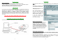
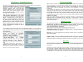
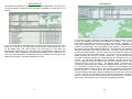
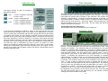
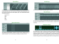
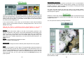
RadioCom 6
DSP-Filter Decoding with the Computer
RTTY-, CW-, PSK, Fax-, SSTV- Decoding,
CAT with Frequency-Management und Frequency-Analyzer
User’s Manual
1
2
Contents
The first steps...........................................................................................................1
Connecting an antenna to the SSB radio ................................................................1
Installation ................................................................................................................2
Registration + Update/Data-Service: .......................................................................3
2-channel operation .................................................................................................4
RadioCom Setup......................................................................................................4
Short Info:.................................................................................................................4
Expansion and Upgrade: .........................................................................................5
Program Preferences...............................................................................................6
Deleting old data after selected days:......................................................................6
Radio Control ...........................................................................................................7
Transmit and Receive Frequency: ...........................................................................8
ScheduleList.............................................................................................................9
SatTracking ........................................................................................................... 10
Signal Tuning – What is a useful signal?.............................................................. 11
Audio-Decoder ...................................................................................................... 12
Audio-Recorder: .................................................................................................... 13
Filter / Equalizer: ................................................................................................... 14
Frequency Scan:................................................................................................... 14
ChannelScan......................................................................................................... 15
SpectrumAnalyzer................................................................................................. 15
AudioScope........................................................................................................... 16
DecoderScope ...................................................................................................... 16
Adjustment Helps:................................................................................................. 16
Frequency Spectrum:............................................................................................ 17
X/Y Tuning Display: .............................................................................................. 17
Q/B PSK:............................................................................................................... 18
RTTY-Decoder ...................................................................................................... 18
FAX-Decoder ........................................................................................................ 20
Picture Receiver:................................................................................................... 20
Filter, Bandwidth: .................................................................................................. 21
Spectrum Analyzer:............................................................................................... 21
Slant Correction .................................................................................................... 21
CW Decoder.......................................................................................................... 22
SSTV Decoder ...................................................................................................... 23
ResultViewer ......................................................................................................... 24
Images .................................................................................................................. 24
Directory and source selection.............................................................................. 25
Save and print FAX............................................................................................... 26
+/- Zoom................................................................................................................ 26
Synchronize .......................................................................................................... 26
Skew correction..................................................................................................... 26
Crop image............................................................................................................ 26
Invert image .......................................................................................................... 26
Rotate image......................................................................................................... 26
ICO RPM:.............................................................................................................. 26
3
Contours, Soften, Sharpen, Brightness ................................................................ 27
Undo / Redo .......................................................................................................... 27
Image Manipulations............................................................................................. 27
Image Download ................................................................................................... 28
Switching local time to UTC/Clock ........................................................................ 28
Print....................................................................................................................... 28
Speed controller .................................................................................................... 28
Play ....................................................................................................................... 28
Time slider............................................................................................................. 28
Text ....................................................................................................................... 29
Icon bar Text ......................................................................................................... 29
Using USB-Serial Adapters:.................................................................................. 30
FAQs ..................................................................................................................... 30
www.bonito.net
www.meteoserver.net
4
Installation
The first steps
Basic requirements:
An operating system: Windows 2000/XP or Windows NT 4.0 SP3
An IBM compatible PC with Intel® Pentium III- CPU 1GHz, 512MB RAM, Graphic
card with a Resolution of 1280x1024, Bi-Directional Soundcard.
Other minimum requirements are stipulated by the system.
IMPORTANT
If you want to use an ICOM PCR1500 / 2500, read the ICOM Manual carefully and
follow ALL the instructions until it’s completely installed. After the succeed
Installation, the ICOM Driver change the Soundcard settings and you can’t hear
other Sounds anymore. To change it back, go to standard settings:
Start\Setting\Control Panel\Sounds and Multimedia Click “AUDIO” and choose
under “Sound Playback” the Soundcard of the PC and do the same with “Sound
Recording”.
DON’T USE THE ICOM SOFTWARE WHILE USING RadioCom!!!
After turning the radio on, you can now insert the CD. The following window
appears:
The CD-Key is burned on the
CD and appears automatically.
Select now your radio from the
„radio selection“ list.
With „Comport Selection“ you
can now select the correct
Comport, in case RadioCom
was not able to find it and
displays an error message.
If the Setup displays error
messages you have to select
the Comport manually.
Connecting an antenna to the SSB radio
If you have an amplified antenna please connect it in the proper way.
Manual Comport Selection
„Find serial port“ will prompt RadioCom to
search for the Radio. „Test serial port“
enables you to test the connectivity of the
COM-port. „Select serial port“ assigns a
concrete COM-port number to a particular
device. For the ICOM PCR/R 1500 or 2500
Radios you have to select the Comport of
your Radio instead the Comport of the
Switchbox.
Audio Output / Input Selection:
If you have different Soundcards or the ICOM PCR/R 1500/2500 installed, you
can choose the Audio Input Card here. You can choose the Audio Input Jack (Line
IN or Microphone) here as well.
When you have completed your selections you are ready to press the „install“
button. RadioCom 6 will now install. When the installation is complete, a
connection layout will open automatically in PDF format.
You will have one icon on the Windows desktop.
1
2
Registration + Update/Data-Service:
2-channel operation
The Program RadioCom must be switched off!
Right after the Installation an Internet Registration Window appears automatically.
You have to register first, before you can run the Program.
RadioCom is using some Recourse (for
example Frequency lists, Timer lists and
Program updates), which you can download
without extra costs via the Internet. There
you simply have to click “Update” and the
following window appears.
Now, you have to register your self. Please
click the Button “Registration”. If you ignore
the entries, you cannot be identified and the
service is always lost in the case of a
problem. If you want to remain anonymous,
set under name, road and city your own
passwords. If no email will register, but only
@ and one point, you’ll not receive an email
with the access code, with which you can reactivate a registration or transfer the code to
another computer.
With a special version of MeteoCom 6 it is possible to operate two radios at the
same time. MeteoCom uses the stereo outlet of the sound card and decodes each
channel separately. This way you can receive a fax message on one channel
while a RTTY signal is decoded on the other. Timer operation is no longer
necessary.
If you bought the version for two radios, simply connect the second radio in the
same way you did the first one. Just use the special audio cable which should be
included in the package. There is a stereo plug on one end of the cable and two
mono plugs on the other. Now insert the stereo plug (two rings) into the linein/microphone jack of the computer and connect the mono plugs in the respective
outlets of your radios.
Later you should make sure that the correct channel is connected to the
respective radio. The simplest way to check this, is to have radio 1 receive fax
while radio 2 receives RTTY. If you find out that the connection is wrong, simply
swap the audio wires.
The computer saves the access code in the Windows registry. You can see and
copy and keep it surely at any time, in order to be able to realize a reactivation of
the Registration.
The suffix changes after each Internet
update. This should be absolutely
considered, if you uninstall the program or
operate it on several computers.
For such a change or the error message
"SUFFIX_OPEN_ERR"
the
manual
activation must be called and the access
code be entered by hand, because a
Registration by Internet is only possible one
time.
If the suffix should have been lost, it is
possible to use a wrong suffix, in order to
eliminate this problem. However this could
happen only 8 times within 90 days.
Changing the radio: You can select a different radio in „Channel selection“ and
close it. You don’t have to reinstall.
3
RadioCom Setup
The installation program is capable of even more. If you should ever change to a
different radio, reinstall or update RadioCom 6 via the Internet, you don’t have to
insert the CD all the time. You can easily open the RadioCom Setup.
You’ll find the RadioCom Setup here:
[Start] [(All) Programs] [Bonito RC60] [Setup RadioCom]
Reinstall: Go to „keep adjustments“ and select whether audio or fax skew were
okay. Press „install“.
Update service: You can update ProMeteo via the Internet by pressing the
“Update” button. ProMeteo automatically downloads the required updates and
installs them. Before updating the Software you have to register your self first.
Short Info:
These operating instructions are not for amateur radio. An assumption is made
that you know how to operate your radio. If not, you should first get used to using
your radio.
RadioCom includes small helps. They will show up when the mouse is on a tool
bar or window. A popup called ToolTip will display. This will show the function of
the respective toolbar or window. If you press the right mouse button from the
‘Context Menu’ you will get further information. This is important for optimal use.
4
Expansion and Upgrade:
The program is built in that way, that later updates will extend and expand the
basic functions. Provided are sending and receiving programs, analyzing tools for
the radio data decoding and new functions. The update service is only available
for registered user and can be done with the RadioCom Setup.
For Upgrades and Sales in the USA contact:
COMPUTER INTERNATIONAL
St. Johns, Michigan 48879 U.S.A.
[email protected]
www.computer-int.com
RadioCom 6 Workbench structure
Program Preferences
Here you can make basic adjustments to the program.
Deleting old data after selected days:
In order to prevent a build-up of old data on your
computer you can have certain data deleted at certain
times. The pre-selected value serves as a good
average.
Tuning Offset:
If your radio has a Frequency offset you can enter the
value in Hz here
Save or Load the Configuration
Here can save or reload the Configuration.
Color Designs
With this little tool you are able to choose a different
design for your RadioCom 4.5² by simply clicking
one of the preinstalled Screens or do your own color
with the “Color picker”. Choose a program part of the
dropdown list and change the color with the Mouse.
After you have a created a nice Design, you can
save and use it or share with your friends. Have fun
with it.
Here are some examples:
5
6
Radio Control
The main window includes the most important control elements for controlling the
radio. You should be familiar with these functions. Your radio may not
support/have all functions. Frequencies can be entered or dialed up and down by
clicking the tuning knob on the left for down or the right for up. The step size is
determined from a drop down menu when you click the button.
The NB button (NOISE BLANKER) will eliminate static and crackling noise. With
AGC you can stabilize the incoming signal if the station is not constant. The signal
strengths can be controlled on the scale high left on the screen. If a signal is
above S7 you can use the button ATT (Attenuation). This reduces the antenna
input if the signal is too strong and the receiver is prone to distortion.
The UBS, LSB, CW, AM, FM, WFM are modes. For most digital modes you
should use USB with a bandwidth of 3 kHz IF. AM is used for normal radio
stations on short wave where 6 kHz is used. Air traffic stations use 15 kHz on
frequencies from 87 to 106 MHz.
Different modes will be activated or deactivated by the program, depending on the
radio you are using. SQL is the squelch, which eliminates interference when there
is no signal being received. VOL is the volume control. It controls the volume
function on the soundcard, not the radio.
The band selectors 80m - 23cm switch to a frequency, which is dependent on the
decoder mode of operation (RTTY, CW, PSK, FAX, SSTV).
On the field MousePad - FrequencySlider you must click and holds the mousebutton and then slides to the left or right. Depending upon that, as far the
frequency will push you more or less strongly adjusted. The switching surface X.
places the frequency movement 100 times more largely.
7
Transmit and Receive Frequency:
You have a list, which contains the important data for the receiver and transmitter.
By double clicking on the frequency line you transfer that data to the program and
the radio. If you press the space bar you will switch to that the frequency. Double
click/ENTER will start the respective decoding process. If you press the headerline (e.g. Name) the list will be sorted. You have 1 Main List that you can’t change,
but 8 Banks for your own propose. You can fill these Banks easily via Drag and
Drop from the Main list.
You can make a new entry, change the existing
data, save, sort or delete entries by using the
right mouse button and choosing the function
you want from the popup menu.
The correct way to enter new data is to select
the mode, receive frequency and adjust the
parameters for proper operation. When you are
satisfied choose “ADD A NEW LIST ITEM” from
the context menu and all the parameters in the
appearing window should be entered. All that
you enter here will be loaded by a double click
from now on.
8
ScheduleList
SatTracking
The „BONITO ScheduleList“ is the proper tool. Since RadioCom 4.5.² this tool is
no longer limited to weather fax but has been expanded to include RTTY and
NavTex.
If you press this button “ScheduleList” the „BONITO ScheduleList“ will open. This
allows you to receive a Fax Transmitter at your position. Now expand your area
on the global map. The radio stations you can receive in your area are
automatically marked in the list. If you select one of these stations, all frequencies
of this station will be displayed, including all transmitting times. Clicking on one
time slot in the transmission schedule will show you the map area covered by this
particular transmission. All times indicated are in UTC.
9
If you press this button “SatTrack” the BONITO Sat tracking will open. If you want
to work with satellite faxes direct from satellites use SatFax. You will have to
know where a satellite is and when it is able to be received. Therefore you will
need some reference data. The most important file is named ‘Satdata.2li’ and is
located in the Data folder. You can update this file regularly. There are found on
the Internet and are called Keplerian elements. The entries for the satellite basic
elements are located in the main frequency list. Only the numbers will be saved
to make an update possible. You can create a list in the basic list section with the
drag and drop method described earlier. Your position will be entered as ‘QTH
locator’ and later you can press ‘Locator to LON/LAT’. If you press the ‘LON/LAT
to Locator’ button the entered geo coordinates will be converted in the ‘LOT/LAT
Locator’. You can find the latest time for the satellites in the ‘Frq & Time’ window.
You can determine from the ‘Basic Data’ list which satellites will be used by
checking the box next to the entry. The buttons ‘Make a Channel List’ and
‘Transfer to Channel Scanner’ transfers all available frequencies to the ChanScan
list. The button ‘Compute a Time List’ and ‘Transfer to Time Manager’ transfers
all satellite passages in the Time List. Be careful of overlapping times and change
them as you like. You will be able to find your satellites on the world map. The
dots are the flight path and the yellow marked points show you when each satellite
is visible. You can choose different views with the buttons next to the world map
(click on “FRQ & Time” first). The mouse works in the window also. A double click
while in the map will make it go to large map with additional options.
10
Reception, Adjustments and Tuning:
Audio-Decoder
The quality of reception is affected by a lot of factors. The antenna and the quality
of the receiver are the biggest. A good antenna can be constructed by taking 6
meters of wire and connect it to the center conductor of a piece of coax long
enough to reach from outside to the radio. Take another piece of wire 6 meters
long and connect it to the shield of the coax. Make sure the connections are
waterproof and will hold up to the pull from the wire. Secure the ends of the wire to
a rope and raise both ends off the ground making a ‘T’. The higher the better. This
is a simple DIPOLE antenna.
There are different types of antennas, verticals, active antennas, loop antennas
and so on. We offer a special antenna, but we never say that our antenna is better
than a perfect wire. Our antenna is only better than all other compromises when a
wire antenna can’t be constructed. And they all were tested.
At first try a clear frequency. If you receive a bad signal you may have to optimize
the antenna or you might wait until the conditions are better. If you try and work
with a signal that has lots of interference it will be difficult to interpret the elements
of the tuning and the functions.
“How to adjust something you can’t see or hear?”
If you have adjusted the signal as best as you can with good receiving conditions
you can also decode it by worth conditions. (???) The tuning and the parameters
in the frequency list are already saved and because of that you can call them up
again. It will not be necessary to make the adjustments again. By doing that you
will see what the decoder can do. It can work well because the decoder does not
register interference’s like the human ear. The speaker will reproduce everything
exactly like it comes in. So you hear a lot of things that the DSP filters out.
The essential characteristic of the program is the sound processing system
together with DSP from your soundcard. This is called DSP. You need to know
following things: The signal will be read in with line-in (or with the microphone
input). Then it will be checked 11000 times per second which parts of the
frequency-spectrum contains the signal. This is what we call sample-frequency.
Then it goes through a number of different complex software processes, which we
call filter. The signal is giving out parallel with listening. You can choose if you
want to hear the original audio (Signal-IN ON) or the filtered audio (Wave-Out
ON). If you want to listen to the output, you need a bidirectional soundcard. In this
case it’s advisable to deactivate Signal-IN ON. Pay attention to adjust the
controller that way, that there is no over modulation (red area). To turn off the
receiver-listening tone use the switch Signal-IN ON. This one turns off the
received signal only. Other tones from the system are still hearable. If you turn off
the speaker (ON), there is no tone out of the speaker - and no sound system
message too.
Signal Tuning – What is a useful signal?
A digital signal is comprised of different sounds or pitches. The distance in time
between the first and the last tone is called bandwidth. Good digital signals will
always be concise and different from all other sounds. You will have figure out
what kind of signal it is: CW, RTTY, SSTV or FAX.
You will soon be able to detect what the signals are by the sounds. We only
decode NAVTEX SITOR and RTTY. But there are a lot of different modes sent
over the air. We do not decode these (BUT OPTIONS ARE AVAILABLE).
Therefore, a meaningless signal may be a useful signal. There are signals, which
we are decoding correctly, but the letters have no meaning. It might be a foreign
language or a cipher code, which would be not readable.
These options normally can be adjusted with the audio-mixer driver of the sound
volume control. In this program part we try to respond these sound-drivers. The
program tries to find the necessary components. It didn’t work always. Therefore
we offer an expedient. Some drivers appear, if you press the Driver button.
Even if you receive correct synoptic number codes you may think they are
useless. This data can be weather data, which will be automatically decoded by
the program.
11
12
Audio-Recorder:
Filter / Equalizer:
The signal recorder is used for recording or
playing back signals.
Play
1. Press = Playback a wave file
2. Press = Stop
Pause 1. Press = Stop Playback
2. Press = Playback will go on
Loop
1. Press = Repeats playback
2. Press = Playback one time
The equalizer can be used like you draw a picture with the mouse. Click anywhere
and keep the button down and draw the desired curve of the filter. If you press the
right button the position will be brought to the maximum. The analyzer can be
zoomed by precise editing. The filter characteristic depends on the filter control.
The button ‘NOISE’ is used for a simple control. It creates a synthetic interference
signal over the whole spectrum. The button ‘Signal’ uses the audio input signal;
this should always be on for the filter mode. On only makes the filtered signal
visible in the spectrum analyzer.
Activate Decoder filter to Wave-Out:
The Equalizer-Filter will be switched over to the ‘Wave Out’.
If you press the ‘WavePlay as Signal In’ button in the Audio Control menu the
wave file becomes the signal input. The volume can be adjusted by the volume
control. Pressing the record button with the REC symbol (the Red Point) activates
a recording of the signal. The input signal is recorded and the recording volume
depends on the control next to the record peak meter. If a wave file is running and
the button ‘WavePlay’ is active as ‘Signal In’ in the audio control panel the signal
will be recorded as the input. There is a slide control below the audio scope that
will allow you to move through the wave file. In the compressor control panel you
can select the type of compression you want to use if you desire. For exact
analysis of a signal you should use PCM 11025 HZ / 16 bit, mono, 22 kb/s mode.
During some compression types will loose important parts of the signal. The file
list has got a context menu for delete, rename, list refresh, change folder and info
about the select wave file.
13
Frequency Scan:
Only the selected frequencies from the list will run. Pressing the start button starts
the scan. The last parameters set in the radio control panel will be used. Only the
frequency is changed. The extracted signal will be displayed on the green 3D
window as a single line after full passage. The audio or S Meter signals as used
for that. A signal event occurs when a signal breaks through the squelch and the
audio becomes useable. Not all receivers have a squelch control. That is why
audio squelch (the control on the Audio Control panel) ‘Asql’ is a much better
squelch. It evaluates the interference much more effectively as compared to
signal strength. For better results you can flat the lines (Flat) and leave the line
without a context out (Not O). The scan process stops when the ‘Stop On Signal’
is pressed. The maximum delay time can be controlled by the value set in ‘Rec
Time’. A value of zero (0) means the process is stopped until the signal is off.
You can record the audio signal with the ‘Rec on Signal’ button. By changing the
values of start, stop and step and press the ‘Make New List’ button a new list of
frequencies is created. You select what frequencies you want by clicking the
small box next to it. If you want to skip a frequency do not check the box.
By stopping the scan process you can find the events in the ‘Scan Event Menu’.
The 3D event window (here in the FRQ Scan) you can activate a channel by
clicking a box that is located on this scale.
14
ChannelScan
The channel scanner works just like the frequency scanner. The modes and the
IF get switched from a list. The list can be created by a drag and drop down menu
from a right hand mouse click in the list box. The entry can be changed as you
like without any influence to the main frequency list. This context menu contains
the following functions:
AudioScope
The AudioScope shows you the original Signal in real time.
DecoderScope
Set frequency
Load
Save
Edit
New
Add
Delete
SpectrumAnalyzer
The DecoderScope shows you the decoded Audio stream in analog and digital.
You have all possible features in it, so you are able to analyze the Signal
completely.
Adjustment Helps:
This digital SpectrumAnalyzer computes the Fast Fourier transform (FFT), a
mathematical process that transforms a waveform into the components of its
frequency spectrum. This is very important for Modes like PSK31 and so on.
You’ll need help in tuning to adjust a signal to make the program work correctly.
The tuning helps will show you where the signal is located and the interference
around it. You will be able to tune the signal in real-time visually. The Scope bar
contains the Spectrum Analyzer, X/Y Tuning Display, and the Signal Scope. The
adjustment helps are shown in the upper part of the screen. They show the
incoming audio so that you can adjust the characteristics from the radio. Slowly
rotate the tuning knob and see how the program reacts to the changes made.
15
16
Frequency Spectrum:
Q/B PSK:
All the audio is displayed and is marked from left to right. The height corresponds
to a stronger amplitude sound. You will see how amplitude will depend on the
pitch. Always try and find that has the highest amplitude. There are exact
technical instructions for which pitch the system is set for. But in practice it
depends on the filter curves of the radio. The unedited frequency list is always
theoretical and not adjusted to your individual radio.
In PSK mode you will have bright patches in the middle of the display when the
signal is properly adjusted.
When tuning you should take care that the signal is placed exactly on the red
lines. The distance between the lines is the bandwidth (called ‘SHIFT’). The
horizontal numbers on the scale show the pitch and the vertical lines show the
volume. This picture shows a RTTY signal with two different pitches. One for Mark
and the other is Space. Both sounds should be placed exactly on the red line.
During a fax signal the bandwidth is higher, the red lines farther apart, with the
major signal on the red line to the right. The adjustment process is explained in
that part of the manual.
X/Y Tuning Display:
On the preceding page a RTTY signal was used as an example whose adjustment
is now displayed on the X/Y display. Get the signal between the red lines (Shift)
by using the frequency spectrum. Then get the cross. If that will not work, you can
play a little bit with the shift. If the shift is correct, the bars will be placed vertical on
top of each other. Finally make sure the crossbars are perpendicular.
RTTY-Decoder
This is how the main screen looks when you are in RTTY mode. The RTTY LIVE
VIEW window shows the received text. Normally you see the last line that is
coming in live. If you want to see saved text you have to click on the RTTY TEXT
VIEW window.
Save Text/Load/Print:
The whole text message is saved in the text memory. You can save a marked part
of a message. You can load the text again in a similar way. The text will be saved
as a RTF file. RTF files can be read, edited and printed by Notepad and WordPad.
To use these functions right mouse click while in the RTTY TEXT VIEW window
and choose the desired function from the popup menu. Create a large text viewer
with a double-click into the text field.
MODE:
Baudot: This mode refers to the usual RTTY mode and is an asynchronous
mode. SYNOP announcements are also sent in this mode.
Sync Baudot: This mode manually synchronizes the Baudot mode.
Sitor B: This is a synchronous mode. It uses a self-error correcting method that
reduces interference problems. Navtex uses a form of this called FEC, Forward
Error Correcting, and is at 100-baud rate.
17
18
Baud rate:
Baud rate is derived from Baudot. It is the speed of the data bits when using
RTTY mode. The most common baud rate is 50 baud but commercial stations for
weather reports often use 75 to 100 baud. Navtex in Sitor-B mode is 100 baud.
FAX-Decoder
Shift and Mark Frequencies:
The shift is the distance in time between the two audio frequencies, sounds, which
determine the RTTY byte or character. It is shown on the frequency analyzer by
the two red lines. The mark frequency determines the position of both red lines
and the shift determines the width of the lines.
Stop Bits:
Each character sent in Baudot must have a start bit and either 1.5 stop bits or 2
bits. This arrangement of bits is what determines the code of the character.
Polarity:
Most receivers and transceivers have USB and LSB functions. Digital data can be
sent in either mode. Most of the time stations use USB. If you are not able to
decode a station correctly you can try and INVERT the signal. The LE and FI
buttons stand LETTERS and FIGURES. There are times when in decoding
Baudot the decoder will get ‘HUNG UP’ in figures or letters. You can force he
program to change by clicking these buttons.
Picture Receiver:
This window is usable when you receive a fax. It is displayed in reduced size.
Right click on the fax window and select the 1:1 big view or make a double-click in
the fax window.
Save:
Activating the AutoSave button (red LED) will start saving the picture from now
until the stop signal is received. Normally the program will do this automatically
with the incoming start signals. The ‘Save This Now’ is deactivated when you start
the program. The picture may not be synchronized at this moment: press the right
mouse button on the margin and the picture will become left synchronized. Click
on the LED you change the state of save.
Save this now:
If you want to save a Fax manually you have to press “save this now”. The whole
picture will be saved. You can view and edit the picture with the View Fax option.
Module and Slant Correction (IOC Part):
Weather Fax’s usually use an IOC of 576 sometimes 288.
Radio amateurs use 267.
IOC 267:
IOC 288:
IOC 352:
IOC 576:
Direct reception of Meteosat and amateur pictures.
Small weather maps with about 800-pixel resolution.
Press pictures with about 1100-pixel resolution.
Large weather maps with about 1800-pixel resolution.
Drum Speed:
The drum speed for most pictures received is 120 RPM. Maps from Moscow come
with different speed like 60, 90, or 120.
Shift and Center Frequency:
Sometimes it is advisable to move the adjustment of the high signal area to the
low. This helps to eliminate unwanted signals. This means you have to move the
two red lines on the horizontal scale of the frequency spectrum display.
19
20
Filter, Bandwidth:
CW Decoder
You can adjust the filter and the passage area of the filter (brighter area).
The filter should go beyond the shift. Other adjustments can make improvements.
Spectrum Analyzer:
This is the display for adjusting the sound frequency. Using USB the fax signal will
have a pile of bars, which deflects to the end of the left red line. The bright area
shows the filters sphere of activity. For getting clear white pictures, the main bar
should be located before the red line on the right. If there is interference you can
move the center frequency up or down to minimize the bandwidth or change the
filter.
The CW program is like the RTTY program. Tune the signal to the red line. You
can do this by frequency or with the mouse moving the signal into the filter
(Provided the program is controlling the radio). Adjustment of the filter width is
from 10 Hz. to 2.3 kHz. You can change the center frequency with the center
control. The ‘POS’ and ‘Zoom’ controls will change the position of the signal.
Save and Print:
You can print and or save received text or just marked text.
Select Font:
This allows you to change the font style of the displayed text.
Slant Correction
During the first test the image will come out skewed. In this case you can rectify
the image by using the „<“ and „>“ buttons. Always use the button that points in
the opposite direction of the skew (e.g. the right button in the case shown in the
image below). You can use the 10x function to do large step correction or 1x for
fine corrections. After completing the correction click on “Slant Calc” which will
apply these values to all other modules and fax frequencies.
Adjustment:
The signal will have to be tuned so that it is exactly on the red line.
Center:
Use this control to move the filter horizontally. This will change the center
frequency.
Width:
This control changes the bandwidth of the filter.
Recommendation: If you are located in Europe, we recommend using the
„Northwood RN London“ broadcast station for skew correction. This station
transmits a synchronizing signal, which can be used as a marker (red circle
on right hand side of the image above).
21
22
SSTV Decoder
SSTV SLANT Correction:
You can correct the slant of a picture by using the ‘10x or 1x’ slant buttons. You
should press and hold the button until the picture is straight. The correction factor
is either 10 pixels or 1 pixel per single click of the button. Pressing and holding the
button will provide a quicker correction.
The ‘Save This Now’ button will save the picture in the receiver window. The
‘AutoSave’ button will save the picture when the lower edge is reached. You can
load and print the picture.
ResultViewer
Looking at the Picture Receiver/Explorer window the left part of the window will
show the received picture. The center will show the saved picture and the right will
show the file name of the saved picture. You can select a file name and load a
saved picture into the editor. If you double click the picture in the receive part of
the window it will be displayed 1:1.
RadioCom comes with the ResultViewer. This is where all saved Pictures and so
on displayed, that where received from the SSB Radio. There are two categories:
„Images“ and „Text“.
You can open this Viewer by pressing this Button:
In the control section of the screen you will be able to work with the filtering
options. There is a quick select function for changing frequencies. This is in a box
labeled SSTV-Freq.
Images
With the ‘M+’ button it is possible to save a tuned frequency. If you tune to
something new you can return to the old saved frequency with the ‘M-‘ button.
Tuning:
A small bright area will be visible on the left of the frequency spectrum. This
appears sometimes on the red line. The red line indicated the synchronizing of the
signal at 1200 Hz. You should tune until the whole signal fits in the marked filter
area. Good tuning shows clear colors. Off shades signify improper tuning. The
filter section has 3 variable adjustments; one manual and 3 preset selection’s ‘LO’
‘MED’ and ‘HI’.
Mode:
You can choose between the 4 different modes.
Martin 1, Scottie 1/2 and Robot 72.
SSTV-FREQ:
These buttons change the radio to different preset frequencies in the program.
AVIS:
There is a start signal in a SSTV signal. This automatically starts the reception of
a picture and saves it at the end of the transmission. This does always work. You
will have to press Receive to start reception. Autosync will try to synchronize the
picture. Pressing the ‘Autosync’ button will resynchronize the picture until the
colors are right. Then you can correct the picture with ManuSync placing it the
proper position.
Here all types of images are displayed, those downloaded from the Internet and
those received in SSB.
23
24
Directory and source selection
Save and print FAX
The image can be saved and printed. The regular processing windows appear
without any special attributes.
Slide bar
+/- Zoom
The image can be enlarged or minimized using the „plus“ and „minus“
buttons. In overview mode you can select a certain area with your mouse.
This is possible only once.
This is where the sources of the various images are:
Weather maps received on the radio, saved and deleted images.
If you would like to archive images, simply drag and drop them to one of the
„banks“. The “automatic deleting routine” will not delete images saved there.
„Images selection“ contains images sorted by date. Double-clicking an
image will bring it up in the large window on the right where it can be
viewed and edited.
You navigate the WeatherFax using the up/down and left/right buttons. You
can also use the black arrows on the right. The button below the arrows
switches the map back to the overview. The image can be zoomed in or out
using the magnifying glass symbols. You can also select a portion of the
image with your mouse. Point your mouse pointer to the upper left corner of
the area you would like to select, click the mouse button and then pull the
mouse to the lower right until the desired area is inside the marked area.
Release the mouse button. ResultViewer will zoom into the selected area.
Below the navigation bar there is a slider, which makes zooming even easier.
Point your mouse to your position and click on the right mouse button. A context
menu will open. Select “Set fix point”. If you now use the zoom slider, you will
always zoom back to the selected position. Even when you are zooming into other
areas you simply need to touch the slider to get back to where you were before.
A received WeatherFax is an image that can usually be edited with common
Windows programs. However, there are no special tools that would enable you to
improve fax reception. With this program you can rotate and synchronize fax
images much more quickly because they are designed specifically RadioCom.
25
Synchronize
If you have received an image where the left edge is displayed in the center of
the image, you can use this function for subsequent synchronization. First
click on the button. Now select the exact spot where you want the edge to be.
Skew correction
Use
this
function
when
an
image
comes
in
skewed.
Click on the upper edge of the image and draw a line along the skewed edge
of the image. Clicking again will correct the image.
Crop image
Click on the button. Then click your left mouse button and draw a rectangle
around the area you want to crop. Release the mouse button. You can now
still manipulate the area by clicking on the edges and pulling them to a
different position. Clicking the right mouse button will finalize the crop.
Invert image
You can receive a fax image in LSB reverse. You do that to improve image
quality. The image will be received inverted. This function will revert the image
to normal.
Rotate image
If the image is arranged wrongly you can rotate it here.
ICO RPM:
If a fax has been recorded with a wrong module or at the wrong speed, it can
be turned into readable form here.
26
Image Download
Contours, Soften, Sharpen, Brightness
„Contour“ displays lines such as isobars more clearly. If a line has been
drawn very softly you can enhance it with this effect. “Soften” and “Sharpen”
add a softening or sharpening effect to the image. “Brightness” controls the
contrast of the image.
Undo / Redo
Use the UNDO command to reverse the last editing action, if possible.
Use the REDO command to reverse the UNDO command.
Image Manipulations
A received weather map is an image that can usually be edited with common
Windows programs. However, there are no special tools that would enable you to
improve fax reception. With this program you can rotate and synchronize fax
images much more quickly because they are designed specifically for RadioCom.
With RadioCom 6 you have the possibility to download Satellite Images to your
Computer and RadioCom create automatically animations. Since these pictures
are not forecasts you can select the time frame for satellite pictures in the “load
pictures for...” selection box. The maximum amount is 24hours. Select the desired
pictures you want to download in the „Image List”.
Switching local time to UTC/Clock
Weather data are always in UTC. To get a better overview of the forecast you can
switch to local time.
Print
Printing the Picture
Speed controller
This controller sets the speed at which animations are played. The speed is also
dependent upon the processing speed of your PC.
Play
Forward and backward.
Time slider
By moving this slider to the left or right you can move data manually.
27
28
Text
Using USB-Serial Adapters:
This is where all received text messages such as forecasts, warnings, NavTex,
etc., are displayed. Texts belonging to certain areas will be stored in the
respective folders. Forecasts for the Mediterranean can only be found in that
folder. This makes finding the proper forecast much easier.
For Hamradio applications you can never have enough COM-ports (serial
interfaces). Unfortunately, some notebook manufacturers terminated the use of
this interface altogether.
In such cases you can overcome the problem by using a USB serial adapter. This
turns a USB connection into a serial port. Theoretically you can create more than
100 COM-ports in this fashion. We have configured RadioCom in such way that it
will recognize such adapters.
RadioCom routinely browses the first 16 COM-ports. When using a USB serial
adapter you should make sure to install it in such way that it is set up as a port
between 1 and 16 (1-9 under WinXP).
Some makers of USB serial ports provide outdated drivers. That’s why we
recommend to check the website of the manufacturer to see whether a newer
driver available. If there is one, you should install it.
We are also able to directly provide you with USB-Serial-Adapters.
FAQs
Icon bar Text
This bar contains the following symbols:
Cloud
Brings RadioCom to the foreground
Print
This will print text messages
Save + Save as
Here you can save a text or overwrite it.
CLR
Deletes the text.
Format
This is where you can format a text.
29
Error message: „COM-Port not found“
Check the configuration of your COM-port in the device manager. If you are not
sure which configuration is correct, press the „reset standard“ button under
„connection configuration“.
Mobile phone and PDA programs like to use the COM-port and are active, even
though the hardware is not connected. This happens because the respective
software is started when the computer boots. Most of the time these programs are
indicated in the info part of the task bar, next to the clock in the lower right corner
of the screen. Click the symbol with your right mouse button and select “exit”. This
will clear the COM-port until the next boot.
Make sure you have the proper switchbox to your radio because RadioCom
specifically looks for it. If a wrong switchbox is connected the above mentioned
error message will appear. The IC-SWL switchbox for example only works with
the ICOM IC-PCR1000, PCR1500 and 2500. The RC-HAM switchbox works with
all Radios. There is a list of radios and their respective switchbox on the CD and
on our homepage under “technical service”.
No signal
Check if the radio is switched on and the connector cable is plugged into the
correct outlets (audio and control cable).
Check the sound card configuration as described on page 2. If you are unsure
about the audio connection of your computer please refer to the PC manual.
The timer records at the wrong time
Check the system time. It should always be set to the time zone and local time of
your location. The MeteoCom timer then calculates the UTC. If you put in the UTC
time yourself, the timer will not function properly.
30
31


![Stealth Protect Series catalogue 2011_We[...]](http://vs1.manualzilla.com/store/data/005809212_1-caf297493bfcf938dba2b64bb0d79842-150x150.png)