1
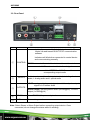
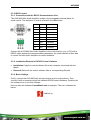
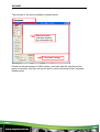
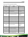
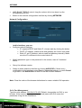
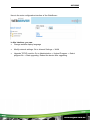
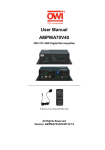
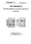
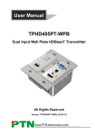
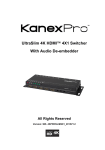
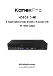
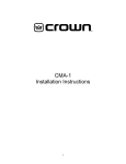
AVG-MA2
Features
The AVG-MA2 Mini Audio Amplifier is a
compact-size digital amplifier (Class-D) with 3
inputs (1 L+R stereo audio, 1 analog audio, 1
optical fiber audio).
3 audio inputs: 1 L+R stereo, 1
analog, 1 optical fiber
Switchable stereo / mono output
Complete EQ management:
including LINE, BASS, TREBLE
Easy volume adjustment via a
rotary knob
Audio loop output
Intuitive LED indicators for input
source, control and volume setting
Controllable via RS232, IR, TCP/IP
(optional)
Web-based GUI
Power off memory function
Easy installation with rack-mounting
design
AVG-MA2
PLEASE READ THIS PRODUCT MANUAL CAREFULLY
BEFORE USING THIS PRODUCT.
This manual is only for operation instruction only, and
not to be used in a maintenance capacity. The
functions described in this version are current as at
March 2015. Any changes of functions and
operational parameters will be updated in future
manual versions. Please refer to your dealer for the
latest product details.
Version 1.0 1/3/15
AVG-MA2
SAFETY OPERATION GUIDE
In order to guarantee the reliable operation of the equipment and safety of the
user, please abide by the following procedures in installation, use and
maintenance:
1. The system must be earthed properly. Please do not use two blade plugs
and ensure the AC power supply ranges from 100v to 240v and from 50Hz
to 60Hz.
2. Do not install the switcher in an environment where it will be exposed to
extreme hot or cold temperatures.
3. This unit will generate heat during operation, please ensure that you allow
adequate ventilation to ensure reliable operation.
4. Please disconnect the unit from mains power if it will be left unused for a
long time.
5. Please DO NOT try to open the casing of the equipment, DO NOT attempt to
repair the unit. Opening the unit will void the warranty. There are high
voltage components in the unit and attempting to repair the unit could result
in serious injury.
6. Do not allow the unit to come into contact with any liquid as that could result
in personal injury and product failure.
AVG-MA2
TABLE OF CONTENTS
Introduction .............................................................................................................. 1
Introduction to the AVG-MA2 ........................................................................ 1.1
Features ....................................................................................................... 1.2
What’s in the Box ........ ……………………………………………………………………2
Product Appearance of the AVG-MA2 .................................................................... 3
Front Panel .................................................................................................... 3.1
Rear Panel .................................................................................................... 3.2
System Connection .................................................................................................. 4
System Applications ..................................................................................... 4.1
Usage Precautions ....................................................................................... 4.2
Connection Diagram ..................................................................................... 4.3
Connection Procedure .................................................................................. 4.4
Audio Output Connection ............................................................................... 4.5
Stereo output (default): 2x50Watt@8Ohm ........................................ 4.5.1
Mono output: 1x100Watt@4Ohm...................................................... 4.5.2
Loop Connection .......................................................................................... 4.6
System Operation..................................................................................................... 5
Front Panel Button Control ............................................................................. 5.1
IR Control ...................................................................................................... 5.2
RS232 Control ............................................................................................... 5.3
Connection with the RS232 Communication Port .............................. 5.3.1
Installation/Removal of RS232 Control Software ............................... 5.3.2
Basic Settings .................................................................................. 5.3.3
RS232 Communication Commands .................................................. 5.3.4
TCP/IP Control .............................................................................................. 5.4
Control Modes ................................................................................. 5.4.1
Control via TCP/IP Communication Software .................................... 5.4.2
GUI for TCP/IP Control ..................................................................... 5.4.3
Port Management ............................................................................ 5.4.4
Specification ............................................................................................................. 6
Panel Drawing .......................................................................................................... 7
Troubleshooting & Maintenance ............................................................................. 8
AVG-MA2
1. Introduction
1.1. Introduction to the AVG-MA2
The AVG-MA2 Mini Audio Amplifier is a compact-size digital amplifier (Class-D) with
3 inputs (1 L+R stereo audio, 1 analog audio, 1 optical fiber audio). It features a
switchable stereo or mono output, and boasts complete EQ adjustment and intuitive
work status display, making it an ideal addition in a classroom or conference room
application.
1.2. Features
3 audio inputs: 1 L+R stereo, 1 analog, 1 optical fiber
Switchable stereo / mono output
Complete EQ management: including LINE, BASS, TREBLE
Easy volume adjustment via a rotary knob
Audio loop output
Intuitive LED indicators for input source, control and volume setting
Controllable via RS232, IR, TCP/IP (optional)
Web-based GUI
Power off memory function
Easy installation with rack-mounting design
AVG-MA2
2. What’s in the Box
1 x Mini Audio Amplifier
4 x Screws
1 x IR Remote
1 x User manual
2 x Detachable Mounting Ears
2 x Pluggable Terminal Blocks (1 3-pin & 1 4-pin)
1 x Power Adapter (DC 33V @ 4A)
1 x IR Receiver (5V, without carrier)
Note: Please confirm if the product and the accessories are all included, if not,
please contact your dealer.
AVG-MA2
3. Product Appearance of the AVG-MA2
3.1. Front Panel
No.
①
Name
Power LED
Input
Selection
Description
Illuminates red when powered on
Press to select any one of the 3 inputs, indicators will light
accordingly
Input 1~3 corresponds to audio sources connected to the 3
audio input ports separately;
②
③
Control
Volume Knob
④
⑤
Volume Bars
1: L+R stereo audio
2: 3.5mm analog audio
3: optical audio
Press to select the audio to be controlled, including LINE,
BASS, TREBLE
Press to mute/unmute the audio
Note: press the button to mute the audio, toggling it
again to restore the audio at the same volume, users
can also rotate the knob to enable audio output at
respective volume.
Rotate the knob to adjust volume, volume bars will
change accordingly
Clockwise Rotation: Volume up
Anticlockwise Rotation: Volume down
Indicate real-time volume setting, 10 bars in total, no volume
bar will be lit when the audio is muted
AVG-MA2
Operation Format: “INPUT SEL” + “CONTROL” + “Volume Knob”
Example: To adjust bass audio of input 3, select input 3 -> choose bass -> adjust
the volume knob.
Note: Pictures shown in this manual are for reference only.
AVG-MA2
3.2. Rear Panel
No.
Description
Name
TCP/IP: (optional) connect with control device to enable IP
control via web-based GUI& TCP/IP communication
software
Indicators will blink when connected to control device
and communicating normally
①
CONTROL
RS232: connect with control device to enable serial control
IR IN: connect with IR receiver to collect infrared signal
Channel Switcher: dial to STEREO or MONO to enable
corresponding output mode
②
INPUTS
Audio input area: 3 audio inputs in total, including 1 stereo
audio, 1 analog audio and 1 optical audio
LOOP: analog audio loop output port, available only when input
signal is L+R stereo audio
③
OUTPUTS
④
DC 33V
Insert DC 33V ,4A power adapter here
⑤
GND
Connect to ground
Audio Output: including stereo audio (2x50W@8Ω), or mono
output (1x100W@4Ω)
Note: Select Stereo or Mono Output before connecting output device. Once
connected, do not change the status while it’s working.
AVG-MA2
4. System Connection
4.1. System Applications
The AVG-MA2’s reliable performance in a control and transmission environment
makes the AVG-MA2 ideal for the IT computer realm, signal monitoring, big screen
displays, conference systems, television broadcast, education, banking and security
institutions etc.
4.2. Usage Precautions
1. System should be installed in a clean environment with temperature and humidity
maintained to within equipment specification.
2. All of the power switches, plugs, sockets and power cords should be insulated
and safe.
3. All devices should be connected before power is turned on.
4. Use straight-thru Cat5e/Cat6 with TIA/EIA T568B terminations to connect TCP/IP
port.
4.3. Connection Diagram
AVG-MA2
4.4. Connection Procedure
Step 1.
Connect audio sources (such as Blu-ray DVD) to INPUT ports of the
device with audio cables;
Step 2.
Dial the Output Selector to mono or stereo, and connect audio output
devices (such as speakers) to audio output port accordingly (Specified in
4.5 Audio Output Connection).
Step 3.
(optional) Insert an IR receiver (5V, without carrier) to IR IN to enable IR
control.
Step 4.
(optional) Connect a control device (e.g. a PC) to RS232 port to enable
serial control.
Step 5.
(optional) Connect a control device (e.g. a PC) to TCP/IP port to enable IP
control.
Step 6.
Plug DC 33V power adaptor to the power port of Mini Audio Amplifier.
AVG-MA2
4.5. Audio Output Connection
4.5.1. Stereo Output (default): 2x50Watt@8Ohm
Dial the switcher to STEREO to enable 2 50Watt@8Ohm stereo output mode.
Connect the amplifier (as shown in the following figure):
4.5.2. Mono Output: 1x100Watt@4Ohm
To enable mono 1x100Watt@4Ohm output, dial the switcher to MONO, and connect
output devices as per the figure below:
4.6. Loop Connection
The AVG-MA2 Mini Audio Amplifier boasts a LOOP port for audio signal loop output.
A maximum of 255 units can be looped within the same operation system. Connect
Mini Audio Amplifiers like this:
AVG-MA2
Then audio signal sent to the first Mini Audio Amplifier is cascaded to other
connected Mini Audio Amplifiers, which enables multiple Mini Audio Amplifiers share
the same audio source.
Note:
1.
2.
Audio loop output is available only when the 1st Mini Audio Amplifier selects
analogue input 1 or 2 as the source.
Audio control operations are not available to looped audio signal.
AVG-MA2
5. System Operation
5.1. Front Panel Button Control
Front panel buttons provides direct audio control including input source selection and
audio EQ adjustment.
Operation Format: Input Sel + Control + Volume Knob (indicators and volume bar
will display real-time operation)
No.
①
Name
Input
selection
Operation
Illuminates red when powered on
②
③
④
Control (EQ
management)
Volume Knob
About the
Volume Bar
Press button INPUT SEL to switch among the 3 inputs
cyclically, relative LED will light to indicate real-time
selection. There are 3 selectable audio sources,
corresponding to the 3 audio input ports on the rear
panel separately.
1: L+R stereo audio
2: 3.5mm analog audio
3: optical audio
Clockwise Rotation: Volume up
Counterclockwise Rotation: Volume down
Volume bar indicates real-time volume level, 10 bars in total,
the higher the volume is, the more bars will be illuminated. In
different EQ control, volume bar tend to act differently:
LINE: Line volume can be 0~60, one more volume
bar will light when the volume is turned up by 6.
BASS: bass volume can be 0~10
TREBLE: treble volume can be 0~10
AVG-MA2
5.2. IR Control
Connect an IR receiver (5V, without carrier) to IR IN port on the rear panel, users are
able to control the amplifier using the included IR remote (see as below):
Input Selection
Unmute
Volume Control
Including LINE, BASS
and TREBLE volume
adjustment
Mute
AVG-MA2
5.3. RS232 Control
5.3.1. Connection with the RS232 Communication Port
The AVG-MA2 Mini Audio Amplifier boasts a 3-pin pluggable terminal block for
serial control. The definition of its pins is listed in the table below.
No.
1
2
3
4
5
6
7
8
9
Pin
N/u
Tx
Rx
N/u
Gnd
N/u
N/u
N/u
N/u
Function
Unused
Transmit
Receive
Unused
Ground
Unused
Unused
Unused
Unused
Connect the AVG-MA2 Mini Audio Amplifier to the control device (e.g. a PC) with a
RS232 cable and set the communication parameters, the control device is then able
to control the Mini Audio Amplifier via control software.
5.3.2. Installation/Removal of RS232 Control Software
Installation Copy the control software file to the computer connected with the
Matrix.
Removal Delete all the control software files in corresponding file path.
5.3.3. Basic Settings
Firstly, connect the AVG-MA2 with an input device and an output device. Then,
connect it with a computer which has installed RS232 control software. Double-click
the software icon to run this software.
Here we take the software CommWatch.exe as example. The icon is showed as
below:
AVG-MA2
The interface of the control software is shown below:
Parameter
Configuration area
Monitoring area,
indicates whether
the command sent
Command Sending
area
Please set the parameters of COM number, baud rate, data bit, stop bit and the
parity bit correctly, only then will you be able to send commands in the Command
Sending Area.
AVG-MA2
TCP/IP Control. RS232 Communication Commands
Baud rate: 9600
Command
Data bit: 8
Stop bit: 1
Parity bit: none
Function
Feedback Example
1A1.
Switch to input 1
A: 1 -> 1
2A1.
Switch to input 2
A: 2 -> 1
3A1.
Switch to input 3
A: 3 -> 1
0A0.
Mute Audio Line out
Mute Audio
0A1.
Unmute Audio Line out
Unmute Audio
600%
Query present working status
A: 1 -> 1
Volume: 30
Bass: 0
Treble: 0
601%
Turn up Line volume by 1
Volume of LINE: 51
602%
Turn down Line volume by 1
Volume of LINE: 51
603%
Turn up Bass volume by 1
Bass of LINE: 4
604%
Turn down Bass volume by 1
Bass of LINE: 4
605%
Turn up Treble volume by 1
Treble of LINE: 4
606%
Turn down Treble volume by 1
Treble of LINE: 4
607%
Restore factory default
Factory Default
A: 1 -> 1
Volume: 45
Bass: 5
Treble: 5
610%
Turn up Line volume by 3
Volume of LINE: 54
620%
Turn down Line volume by 3
Volume of LINE: 51
61X%
Turn up Line volume by X
Volume of LINE: 54
62X%
Turn down Line volume by X
Volume of LINE: 54
Preset line volume, [xx] can be
00~60, 61 degrees in total.
Volume of LINE: 50
7[x][x]%
AVG-MA2
8[x][x]%
Preset the bass level, [xx] can be
00~10, 11 degrees in total.
Bass of LINE: 7
9[x][x]%
Preset the treble level, [xx] can be
00~10, 11 degrees in total.
Treble of LINE: 7
Get the IP of the device
IP: 192.168.0.178
GetIP;
5.4. TCP/IP Control
The AVG-MA2 Mini Audio Amplifier boasts option TCP/IP port for IP control.
Default settings: IP: 192.168.0.178; Subnet Mast: 255.255.255.0; Gateway:
192.168.0.1, Serial Port: 4001.
The IP & gateway can be changed as you need, Serial Port cannot be changed.
Connect the ethernet port of the control device and TCP/IP port of Mini Audio
Amplifier, and set same network subnet for the 2 devices, users are able to control
the device via a web-based GUI or TCP/IP communication software.
5.4.1. Control Modes
The AVG-MA2 Mini Audio Amplifier can be controlled by PC without Ethernet access
or PC(s) within a LAN.
Controlled by PC without ethernet access
Connect a computer to the TCP/IP port of the 4K HDBaseT 8x8 Matrix Switcher, and
set its network subnet to the same as the 4K HDBaseT 8x8 Matrix Switcher’s.
Same network
segment as the
switcher
AVG-MA2
Controlled by PC(s) in LAN
Connect Mini Audio Amplifier, a router and several PCs to setup a LAN (as shown in
the following figure). Set the network subnet of the Mini Audio Amplifier to the same
as the router’s, then PCs within the LAN are able to control Mini Audio Amplifier.
Follow these steps to connect the devices:
Step 1.
Connect the TCP/IP port of the Mini Audio Amplifier to Ethernet port of PC
with straight-thru CAT5e/6.
Step 2.
Set the PC’s network subnet to the same as the Mini Audio Amplifier’s.
Step 3.
Set the Mini Audio Amplifier’s network subnet to the same as the router.
Step 4.
Set the PC’s network subnet to the original setting.
Step 5.
Connect the Mini Audio Amplifier and PC(s) to the router. PC(s) within the
LAN are able to control the Mini Audio Amplifier asynchronously.
AVG-MA2
5.4.2. Control via TCP/IP Communication Software
1. Connect a computer and the AVG-MA2 Mini Audio Amplifier to the same
network. Open the TCPUDP software (or any other TCP/IP communication
software) and create a connection, enter the IP address and port of AVG-MA2
Mini Audio Amplifier (default IP: 192.168.0.178, port:8080):
2. After connecting successfully, we can enter commands to control the AVG-MA2
Mini Audio Amplifier, as below:
Enter your command here.
Here you will receive
the feedback when a
command is sent.
AVG-MA2
5.4.3. GUI for TCP/IP Control
The AVG-MA2 Mini Audio Amplifier comes with a built-in GUI for convenient TCP/IP
control. GUI allows users to interact with the Mini Audio Amplifier through graphical
icons and visual indicators.
Type 192.168.0.178 (default IP, changeable via GUI) into your browser, it will enter
the log-in interface as shown as below:
Type in the username and password:
Name: admin; Password: admin (default setting, changeable via GUI)
Click LOGIN, it will show the audio selection interface as shown below:
Audio Selection:
In this interface, you can:
Select input
Mute/ Unmute
AVG-MA2
LINE/ BASS/ TREBLE control: drag the volume dot to turn down/ up the
corresponding volume
Switch to the network configuration interface by clicking NETWORK
Network Configuration:
In this interface, you can:
Configure network settings:
IP: supports DHCP and Static IP, choose state by clicking the button
DHCP: IP Address, subnet mask and gateway are fixed in this mode
Static IP: set IP Address, subnet mask and gateway manually. Make
sure the IP is different to the control device’s
Modify password: type in new password in the column, max at 5 numbers/
letters
Query the software version
Switch to audio selection interface by clicking AUDIO SEL If there is any
modification in this interface, press Save to restore the settings, or press Cancel
to go back. Click ADUIO SEL to return to the NETWORK interface.
Note: Clear the cache of the browser beforehand to ensure reliable GUI operation.
5.4.4. Port Management
Type the units address 192.168.0.178:100 (Default, changeable via GUI) in your
browser. Enter correct username and password (same with GUI name and
password) to log into the WebServer:
AVG-MA2
Here is the main configuration interface of the WebServer:
In this interface, you can:
Change website display language
Modify network settings: Go to Internet Settings -> WAN
Upgrade TCP/IP module: Go to Administration -> Upload Program -> Select
program file -> Start upgrading. Reboot the device after upgrading.
AVG-MA2
6. Specification
Input
Output
Input Signal
1x L+R stereo
audio
1x 3.5mm
analog audio
1x Optical Fiber
audio
Output
Signal
1x LOOP
2x Stereo audio/ 1 Mono audio
Connectors
2x RCA
1x 3.5mm TRS
plug
1x SPDIF
Connectors
1x 3.5mm jack
1x 4-pin 5.08mm connector
Input
impedance
>10KΩ
Damping
coefficient
>100
Control
Control
Ports
1x RS232 (3-pin pluggable terminal block)
1x IR IN (3.5mm female)
1x TCP/IP (RJ45 female, optional)
Panel
Control
Front panel buttons & rear panel switcher
General
SNR
80dB
Separation
75dB
20KHz
Voltage
Gain
32dB
Output
Power
Power
Supply
DC 33V 4A
Power
1.48W
Consumption
Work
0~50℃
Temperature
Dimensions
(W*H*D)
THD+ Noise
20Hz~ Damping
coefficient
Reference
Humility
148 x44 x165
Weight
mm
NOTE: All nominal levels are at ±10%.
1%@1KHz 50W
100
1×100W@4Ω/2×50W@8Ω
10%~90%
0.72kg
AVG-MA2
7. Panel Drawing
AVG-MA2
8. Troubleshooting & Maintenance
Problem
No output audio
Cause
Loose or broken
connection at input/
output end
No connected source at
the chosen input
channel
Audio has been muted
Wrong output
connection
Solution
Reconnect the devices.
Insert source into the port or change
to other input channels.
Press the volume knob to unmute.
Connect output according to different
transmission mode (stereo or mono).
Power indicator Not connected to power Reconnect the power adapter.
is off and the
device is non- Loose or broken power
Replace the power cable.
cable
responsive
No TCP/IP
control
No RS232
control
Control device and Mini Set the network subnet of control
Audio Amplifier are on device to the same as the Mini Audio
different network subnet Amplifier’s.
Network subnet of Mini
Audio Amplifier is
different with LAN’s.
Loose or broken RS232
connection
Set the network subnet of Mini Audio
Amplifier to the same with LAN’s.
Reconnect the devices or change to
another RS232 cable.
Wrong command
Send the exact command listed in
4.3.3.
Wrong communication
protocol settings
Set the protocol to: Baud rate: 9600;
Data bit: 8; Stop bit: 1; Parity bit:
none.
Run out of battery
Change batteries.
No IR control
No loop output
Exceeds effective
Adjust control distance and angle.
control distance or angle
No connected source at
Connect audio source to input 1 or 2
input 1 & 2 of the 1st
of the 1st Mini Audio Amplifier.
Mini Audio Amplifier
Wrong input selection at
the 1st Mini Audio
Amplifier
Select input 1 or 2 at the 1st Mini
Audio Amplifier