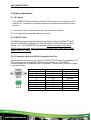
1
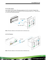
AVG-HDWP70TX-IR
Features
Selectable HDMI/ VGA with audio input
Supports VGA output resolutions up to 1920x1200
High bandwidth: 10.2Gbps
In-built scaler function, supports scaling of
HDMI/ VGA signals to match the native
resolution of the display
Transmits HDMI signals up to 4K
Compliant with HDMI 1.4, supports 1080p 3D
HDCP compliant, equipped with HDCP autotracking function
Provides auto-switching capability
Supports multiple control methods
including front panel buttons, IR, and
AVG-HDWP70TX-IR is a Decora style
transmitter that installs in a double-gang wall
plate to provide a convenient interface for HDMI
and VGA input sources
RS232, supports bi-directional IR &
RS232 pass-through control.
Supports firmware upgrading via USB.
DC 12V power output
Powered by local a power pack or PoC connection
up to 60m
Aluminum design for efficient better cooling
AVG-HDWP70TX-IR
PLEASE READ THIS PRODUCT MANUAL CAREFULLY
BEFORE USING THIS PRODUCT.
This manual is for operational use only, and not to be
used in a maintenance capacity. The functions
described in this version are current as at March 2015.
Any changes of functions and operational parameters
will be updated in future manual versions. Please refer
to your dealer for the latest product details.
Version 1.0 1/3/15
AVG-HDWP70TX-IR
SAFETY OPERATION GUIDE
In order to guarantee the reliable operation of the equipment and safety of the
user, please abide by the following procedures in installation, use and
maintenance:
1. The system must be earthed properly. Please do not use two blade plugs
and ensure the AC power supply ranges from 100v to 240v and from 50Hz
to 60Hz.
2. Do not install the switcher in an environment where it will be exposed to
extreme hot or cold temperatures.
3. This unit will generate heat during operation, please ensure that you allow
adequate ventilation to ensure reliable operation.
4. Please disconnect the unit from mains power if it will be left unused for a
long time.
5. Please DO NOT try to open the casing of the equipment, DO NOT attempt to
repair the unit. Opening the unit will void the warranty. There are high
voltage components in the unit and attempting to repair the unit could result
in serious injury.
6. Do not allow the unit to come into contact with any liquid as that could result
in personal injury and product failure.
AVG-HDWP70TX-IR
TABLE OF CONTENTS
Introduction .............................................................................................................. 1
Introduction to the AVG-HDWP70TX-IR ....................................................... 1.1
Features ....................................................................................................... 1.2
Package List ................ ……………………………………………………………………2
Product Appearance ................................................................................................ 3
Front Panel ................................................................................................... 3.1
Side Panel .................................................................................................... 3.2
Rear Panel.................................................................................................... 3.3
System Connection .................................................................................................. 4
System Application ....................................................................................... 4.1
Usage Precautions ....................................................................................... 4.2
System Diagram ........................................................................................... 4.3
Connection Procedure .................................................................................. 4.4
12V DC Output ............................................................................................. 4.5
PoC Solution................................................................................................. 4.6
System Operations................................................................................................... 5
IR Control ..................................................................................................... 5.1
RS232 Control .............................................................................................. 5.2
Connection with RS232 Communication Port ................................. 5.2.1
Installation of the RS232 Control Software ..................................... 5.2.2
Basic Settings ................................................................................. 5.2.3
RS232 Communication Commands ............................................................ 5.3
Firmware Update via USB ............................................................................ 5.4
Specification ............................................................................................................. 6
Panel Drawing .......................................................................................................... 7
Troubleshooting & Maintenance ............................................................................. 8
AVG-HDWP70TX-IR
1. Introduction
1.1. Introduction to the AVG-HDWP70TX-IR
AVG-HDWP70TX-IR is a Decora style transmitter that installs in a double-gang wall
plate to provide a convenient interface for HDMI and VGA input sources.
It has 1 HDMI IN, 1 VGA IN, 1 Audio IN and 1 HDBT OUT with PoC. It supports
VGA with a full HD scaler, and HDMI 1.4 with 4k & 3D. Input signals support autoswitching. The HDBaseT output supports 60m UHD video transmission with PoC,
enables bi-directional IR and RS232 communication between HDWP70TX-IR and
a remote device.
With its PoC solution, the AVG-HDWP70TX-IR can be powered by a far-end PoC
receiver.
1.2. Features
Selectable HDMI/ VGA with audio input
Supports VGA output resolutions up to 1920x1200
High bandwidth: 10.2Gbps
Built-in scaler function, supports scaling HDMI and VGA signals to match
the native resolution of the display
Transmits HDMI signals up to 4K
Compliant with HDMI 1.4, supports 1080p 3D
HDCP compliant, equipped with HDCP auto-tracking function
Provides auto-switching capability
Supports multiple control methods including front panel buttons, IR, and
RS232, supports bi-directional IR & RS232 pass-through control.
Supports firmware upgrading via USB.
DC 12V power output
Powered by local power pack or PoC connection up to 60m
Aluminum design for efficient cooling
AVG-HDWP70TX-IR
2. Package List
1 x AVG-HDWP70TX-IR
4 x Screws
3 x Pluggable Terminal Blocks (1 2-pin block, 1 3-pin block, and 1 4-pin block)
1 x Face Plate (Selectable)
4 x Screws (for the face plate)
1 x Power Adapter (DC 12V 2A, selectable)
1 x User Manual
Note: Please confirm if the product and the accessories are all included, if not,
please contact your dealer.
AVG-HDWP70TX-IR
3. Product Appearance
3.1. Front Panel
Note: Pictures shown in this manual are for reference only.
No.
①
Name
Power
indicator
②
IR IN
③
IR OUT
④
⑤
RS232
VGA IN
Description
Illuminates red when power is on
Connect with IR receiver, receive IR signals sent from
the IR Emitter connected to the far-end receiver
Connect with IR Emitter, IR signals emitted from the IR
emitter are received by the IR receiver connected to
the far-end receiver.
Serial port, 3-pin pluggable terminal block, connects
with the control terminal to control the HDWP70TXIR, supports bi-directional RS232 control (send
control signal from local or receive control signal sent
from far-end devices).
Connect with a VGA source device.
The indicator:
illuminates yellow when there is VGA signal input
illuminates green when the signal source is chosen as
AVG-HDWP70TX-IR
⑥
AUDIO IN
⑦
HDMI IN
⑧
LINK
&HDCP
⑨
RESET
⑩
FIRMWARE
input source
turns off when there is no VGA input signal
Connect with the audio output socket of the VGA source
device, delivers synchronous audio with the VGA signal
source when VGA is the source signal.
Connect with HDMI source device.
The indicator will illuminate yellow when there is VGA
signal input and illuminates green when the signal
source is chosen as input source.
LINK: Twisted Pair Link status indicator, illuminates
green when successfully connected.
HDCP: HDCP compliance indicator, illuminates
green when the source signals is with HDCP; blinks
when it is not with HDCP; and turns off when there
is no source signal.
Press the button to reboot HDWP70TX-IR.
USB port, used for firmware updates
Plug a flash disk or other storage device with update file
(MERGE.bin), and send command 50698% to update
firmware.
Note: Pictures shown in this manual are for reference only.
AVG-HDWP70TX-IR
3.2. Side Panel
No.
Name
①
HDBT OUT
Description
RJ45 port, connect with receiver via a CAT5e/6 cable to
deliver Audio/ Video signals, supports PoC.
Note: Pictures shown in this manual are for reference only.
3.3 Rear Panel
No.
Name
①
Power In
②
Power
Out
③
RS232
Description
Power in port, 2-pin pluggable terminal block, connect with a
DC 12V power adapter
Power out port, for powering 3rd party equipment
Serial port, connects with a far-end receiver, supports
bi-directional RS232 control (send control signal from local
TX or receive control signal sent from far-end devices).
Note: Pictures shown in this manual are for reference only.
AVG-HDWP70TX-IR
4. System Connection
4.1. System Applications
Reliable performance for control and transmission makes the AVG-HDWP70TX-IR
ideal in the IT computer space, signal monitoring, big screen displays, conference
systems, television broadcast, education, banking and security institutions etc.
4.2. Usage Precautions
1. System should be installed in a clean environment with temperature and humidity
maintained to within equipment specification.
2. All of the power switches, plugs, sockets and power cords should be insulated
and safe.
3. All devices should be connected before power is turned on.
4.3. Connection Diagram
Note: Pictures shown in this manual are for reference only.
AVG-HDWP70TX-IR
4.4. Connection Procedure
Step 1.
Connect HDMI source device (e.g. Blu-ray DVD) to the HDMI input port of
the AVG-HDWP70TX-IR with HDMI cable. Connect a VGA source device
(e.g. PC) to the VGA input port of AVG-HDWP70TX-IR with VGA cable
Step 2.
Connect an AVG-HD402PR to the HDBT port on the rear panel with
twisted pair.
Step 3.
Connect a HDMI display to the HDMI OUT port of AVG-HD402PR
Step 4.
Connect a control terminal to the RS232 port on the front panel of AVGHD402PR.
Step 5.
Both AVG-HDWP70TX-IR and AVG-HD402PR have IR IN and OUT.
When one model is used for IR signal receiver, the IR signal must be
sent out by the other model.
For example: When “IR IN” of AVG-HDWP70TX-IR connects with
an IR receiver, the IR transmitter must connect to IR OUT of the
AVG-HD402PR.
The IR signal can be transmitted bi-directionally between the
AVG-HDWP70TX-IR and AVG-HD402PR.
Step 6.
Connect a control device (e.g. PC) to the RS232 port of AVG-HDWP70TXIR or AVG-HD402PR (bi-directional RS232 control, either is available)
Step 7.
Connect a DC 24V power adaptor to the power port of the AVG-HD402PR.
The AVG-HDWP70TX-IR is able to get power from the AVG-HD402PR
with the PoC solution.
Note: AVG-HDWP70TX-IR supports unidirectional PoC, i.e, AVG-HDWP70TX-IR
can get power from far-end PoC devices with the PoC function. However, it can’t
power a far-end PoC device when the power supply is connected to HDWP100TXIR.
AVG-HDWP70TX-IR
4.5. 12V DC Output
AVG-HDWP70TX-IR has a 12V power output port on the rear panel. Connect the
12V power output port of AVG-HDWP70TX-IR to the power port of a 3rd Party Device
for convenient localized powering.
Note: Pictures shown in this manual are for reference only.
4.6. PoC Solution
Note: Pictures shown in this manual are for reference only.
AVG-HDWP70TX-IR
5. System Operations
5.1. IR Control
AVG-HDWP70TX-IR provides an IR IN/ IR OUT socket for connection to an IR
receiver/ IR Transmitter to attain bi-directional IR transmission with the far-end
receiver.
1. Control the far-end output device from the local matrix location.
2. Control the local input/output device remotely.
5.2. RS232 Control
As RS232 can be transmitted bi-directionally between the AVG-HDWP70TX-IR
and AVG-HD402PR, enabling it to control a third party RS232 device locally or
control t h e AVG-HDWP70TX-IR remotely. When controlling a third party
RS232 device, the baud rate of this device should be 2400, 4800, 9600, 19200,
38400, 57600 or 115200.
5.2.1 Connection with the RS232 Communication Port
As well as the front control panel, the AVG-HDWP70TX-IR can be controlled by a 3rd
Part control system through the RS232 communication port. This RS232
communication port is a female 9-pin D connector. The definition of its pins is listed
in the table below.
No.
1
2
3
4
5
6
7
8
9
Pin
N/C
Tx
Rx
N/C
Gnd
N/C
N/C
N/C
N/C
Function
Unused
Transmit
Receive
Unused
Ground
Unused
Unused
Unused
Unused
AVG-HDWP70TX-IR
5.2.2. Installation/Removal of RS232 Control Software
Installation Copy the control software file to the computer connected with the
Matrix.
Removal Delete all the control software files in corresponding file path.
5.2.3. Basic Settings
Firstly, connect the AVG-HDWP70TX-IR with an input device and an output device.
Then, connect it with a computer which is installed with RS232 control software.
Double-click the software icon to run this software.
Here we take the software CommWatch.exe as example. The icon is pictured as
below:
AVG-HDWP70TX-IR
The interface of the control software is shown below:
Parameter
Configuration area
Monitoring area,
indicates whether
the command sent
works.
Command Sending
area
Please set the parameters of COM number, baud rate, data bit, stop bit and the
parity bit correctly, only then will you be able to send commands in the Command
Sending Area.
AVG-HDWP70TX-IR
5.3. RS232 Communication Commands
Baud rate: 9600
Command
50701%
50704%
50770%
50771%
50619%
Data bit: 8
Stop bit: 1
Parity bit: none
Function
System Commands
Switch to HDMI input
Switch to VGA input
Enable auto-switching
Disable auto-switching
Resolution Commands
Change the resolution to 1360X768
HD
Feedback Example
Switch to HDMI
Switch to VGA
Auto Switching
Manual Switching
Resolution:
1360x768
Change the resolution to 1024X768
50626%
XGA
Resolution:
1024x768
Change the resolution to 1280X720
50627%
720P
Resolution:
1280x720
Change the resolution to 1280X800
50628%
WXGA
Resolution:
1280x800
Change the resolution to 1920X1080
50629%
1080P
Resolution:
1920x1080
Change the resolution to1920X1200
50620%
WUXGA
Resolution:
1920x1200
Change the resolution to1600X1200
50621%
UXGA
Resolution:
1600x1200
Setup Commands
Set the brightness to xx. XX ranges
502xx%
503xx%
504xx%
505xx%
50606%
from 00 to 99
Set the contrast to xx. XX ranges
from 00 to 99
Set the saturation to xx. XX ranges
from 00 to 99
Set the sharpness to xx. XX ranges
from 00 to 99
Auto-adjust the input parameter
Brightness: xx
Contrast: xx
Saturation: xx
Sharpness: xx
VGA Input Auto
AVG-HDWP70TX-IR
Command
Function
50607%
Adjust the color temperature
50608%
Set the aspect ratio
50614%
Set the picture mode
50699%
Check the system version
Switch to RS232 mode 1, enable
50779%
scaler to control far-end devices
Switch to RS232 mode 2, enable
50780%
far-end devices to control scaler
Feedback Example
Color Temperature:
xx (xx
can be medium,
warm, user, or
cool)
Aspect Ratio: xx (xx
can be
16:9, 4:3, or auto.)
Picture Mode: xx (xx
can be dynamic,
standard, mild, or
user.)
Version Vx.x.x
RS232 Mode 1:
RS232
Control Scaler &
Remote
RS232 Mode
2:RS232 &
Remote Control
Scaler
Set the HDCP status of HDMI output
50790%
50791%
50792%
socket to Active
Set the HDCP status of HDMI output
socket to On
Set the HDCP status of HDMI output
50698%
socket to Off
Software update
50617%
Reset to factory default
HDCP Active
HDCP On
HDCP Off
Query Commands
50632%
50633%
Check the output resolution
Check the picture mode
Resolution: xx
Picture Mode: xx
HDC
50793%
Check HDCP status
P Off
HDC
P On
HDCP Active
AVG-HDWP70TX-IR
Command
50635%
Function
Check the image aspect ratio
Feedback Example
Aspect Ratio: xx
50636%
50637%
50638%
50639%
50640%
Check the brightness
Check the contrast
Check the saturation
Check sharpness
Check the color temperature
Brightness: xx
Contrast: xx
Saturation: xx
Sharpness: xx
Color Temperature:
xx
50678%
Adjustment Commands
Enable screen output adjusting
50679%
Disable screen output adjusting
50670%
Move the image to left
50671%
Move the image to right
50672%
Move the image up
50673%
Move the image down
Enter Output
Position Adjust
Exit Output Position
Adjust
Output Position
Adjust X xx
Output Position
Adjust X xx
Output Position
Adjust Y xx
Output Position
Adjust Y xx
Stretch left from left side (increase
50674%
Output Width Adjust
xx
image width)
Pull right from left side (decrease
50675%
Output Width Adjust
xx
image width)
Stretch upwards from bottom side
50676%
Output Height Adjust
xx
(decrease image height)
Stretch downwards from bottom side
50677%
50772%
50773%
50774%
50775%
(increase image height)
Output Height Adjust
xx
EDID Commands
EDID pass-through
Set EDID data to 1080P
EDID: bypass mode
PCM
2.0ch
Set EDID data to 1080P Dolby 5.1
Set EDID data to 1080P3D Dolby
5.1
EDID:1080P&PCM
2ch
EDID:1080P&5.1ch
EDID:1080P3d&5.1c
h
AVG-HDWP70TX-IR
Command
50776%
Function
Set EDID data to 1080i PCM 2.0ch
Feedback Example
EDID:1080i&PCM
2ch
Set EDID data to 4K*2K PCM
50777%
2.0ch
EDID:4K&PCM 2ch
EDID:1080P&
50778%
Check EDID data
CM 2ch
EDID:1080P&
.1ch
EDID:1080P3d
&5.1ch
Program EDID file, send EDID data
50799%
within 10s
EDID:4K&PCM 2ch
Waiting for edid
within 10
secs!
Notes:
1. Please disconnect all the twisted pairs before sending command
EDIDUpgrade[X].
2. In above commands, “[”and “]” are symbols for easy reading and do not need to
be typed in actual operation.
3. Please remember to end the commands with the ending symbols “.” and “;”.
4. Type the command carefully, it is case-sensitive.
AVG-HDWP70TX-IR
5.4. Firmware Update via USB
To meet the needs of different users or further additional functions, the firmware of
the AVG-HDWP70TX-IR can be upgraded via USB. If the unit needs upgrading
please download the latest firmware file and then you are able to upgrade it through
the update .exe file. Copy the .exe file to the programming PC and double click the
program to upgrade the firmware.
When the program is running normally, it will display the interface (as shown in the
next figure), please press the button
press the button
and choose the upgrade file, and then
. It is ready to upgrade.
When updates are done, it will appear with a window showing the message Update
success.
Note: The COM number connected with PC is available only between 1 to 9.
AVG-HDWP70TX-IR
6. Specification
Audio
Input
Input Signal
Connector
Input Signal
Connector
1 HDMI, 1 VGA, 1 AUDIO, 1 IR, 1
RS232
1 19-pin Type A HDMI female; 1
15-pin VGA; 1 3.5mm stereo jack;
1 3.5mm IR socket;1 3-pin
pluggable terminal block
Output
1 HDMI, 1 VGA, 1 AUDIO, 1 IR, 1
RS232
1 19-pin Type A HDMI female; 1
15-pin VGA; 1 3.5mm stereo jack;
1 3.5mm IR socket;1 3-pin
pluggable terminal block
Input Signal
Connector
Input Signal
Connector
Input Signal
1 HDMI, 1 VGA, 1 AUDIO, 1 IR, 1
RS232
Video
Input Signal
Frequency
Response
20Hz~20KHz
Frequency
Response
Impedance
SNR
>10Ω
>85db@20Hz~20KHz
General
VGA: 800 x600, 1024 x 768, 1280 x
800,1280 x 1024,
1440 x 900,1600 x 1200, 1920
x 1080, 1920 x 1200; HDMI:
4Kx2K, 1080p 3D,
1080P(HD)/1080i/720P/576P/5
76i/480P/480i
1080P≤60M (PoC)
4Kx2K≤40M (PoC)
Impedance
SNR
10.2Gbps
Supports HDMI1.4 and HDCP
DC 12V 2A; 9.6W
-10 ~ +40℃
10% ~ 90%
Decora style two gang
104.5 x 89 x 44 mm
0.29Kg
Bandwidth
HDMI Standard
Power Supply
Temperature
Humidity
Chassis Dimension
Dimension (W*H*D)
Weight
Resolution
Transmission
Distance
Bandwidth
HDMI Standard
Power Supply
Temperature
Humidity
Chassis Dimension
Dimension (W*H*D)
Weight
Resolution
Transmission
Distance
AVG-HDWP70TX-IR
7. Panel Drawing
88.72 mm
Tx
Rx
46.00 mm
Note: Pictures shown in this manual are for reference only.
AVG-HDWP70TX-IR
8. Troubleshooting & Maintenance
Problems
Colour loss or no
video signal output
on HDMI display
Causes
Solutions
The connecting
cables may not
be connected
correctly or unit
may have a fault
Check whether the cables are
connected correctly and in good
working condition.
POWER indicator
doesn’t work or
respond to any
operation
Loose or failed
power cord
connection
Ensure the power cord
connection is good
Cannot control the
device with 3rd party
device (e.g. a PC)
through RS232 port
Wrong RS232
communication
parameters
Make sure the RS232
communication parameters are
correct set.
Poor grounding
Check the grounding and make
sure it is connected well.
No HDMI signal
output in the device
while local HDMI
input is in a normal
working state
Output image is
noisy
Static becomes
stronger when
connecting the video
connectors
Cannot be controlled
through RS232 port or
front panel buttons
The unit may
have a previous
fault
Send it to an authorized
dealer for repair.
If your problem persists after following the above troubleshooting steps, seek
further help from your authorized dealer.