1
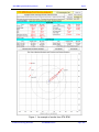
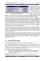
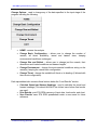
STA SPM Single Point Mooring Analysis Revision 1 Page i STA SPM A PROGRAM FOR STATIC ANALYSIS OF SINGLE POINT MOORED VESSELS USER MANUAL AND TECHNICAL DOCUMENTATION Revision 1a Manual Prepared by STEWART TECHNOLOGY ASSOCIATES 728 Bering Drive, Unit M Houston, TX 77057 Tel: (713) 789-8341 Fax: (713) 789-0314 www.stewart-usa.com E-Mail: [email protected] July 2, 2007 © Stewart Technology Associates STA SPM Manual.doc July 2, 2007 STA SPM Single Point Mooring Analysis Revision 1 Page ii EXTRACTS FROM LICENSE AGREEMENT LIMITATION OF USE This License is granted to the USER for an indefinite period. The USER agrees that no individual, outside consultant, government organization, or any person who is not on permanent staff with the USER or under direct in-house control of USER shall have access to the PROGRAM or shall use the PROGRAM for any purpose at any time. The use of the PROGRAM is not limited to a single machine, and the USER may make copies of PROGRAM and run it on several machines simultaneously. The USER agrees to make any reasonable effort to assure that the PROGRAM file or disk is not copied without authorization by OWNER, and that all users in USER's organization are familiar with these Limitations of Use. The USER agrees not to modify, copy, sell, lease, rent, give free of charge, or otherwise distribute or alter the PROGRAM or any part thereof to any individual, government agency, or organization outside of the USER organization. COPYRIGHTS All copyrights to the PROGRAM are reserved by OWNER. All versions of the PROGRAM are copyrighted by OWNER worldwide, beginning with 1991. The following is a trademark of OWNER: STA SPM. The USER shall clearly and distinctly indicate the copyright in all published and public references to the PROGRAM. WARRANTY While the OWNER has carefully developed the software and the software has been tested for accuracy and proper functioning, nevertheless the OWNER cannot guarantee its accuracy and correctness. If the software fails to perform correctly as a result of errors or omissions by the OWNER or its staff, the OWNER will at its discretion rectify those errors and omissions free of all charges to the USER. This shall be the limit of the OWNER's liability in this respect. OWNER warrants that it has the right to grant this license. The PROGRAM and its documentation is sold "as is," and the USER assumes the entire risk as to quality and performance. HOLD HARMLESS The OWNER shall not be liable to the USER or any other party for any design, performance or other fault or inadequacy of the PROGRAM or its manual, or for any direct or implied damages of any kind arising out of or in any way related to or connected with any use of the PROGRAM. © Stewart Technology Associates STA SPM Manual.doc July 2, 2007 STA SPM Single Point Mooring Analysis Revision 1 Page iii CONTENTS Section and Subject 1.0 2.0 3.0 4.0 5.0 6.0 7.0 8.0 9.0 Page No. INTRODUCTION ........................................................................................................................... 1 APPLICATION............................................................................................................................... 3 THEORY ....................................................................................................................................... 3 RESULTS ...................................................................................................................................... 3 LOADING AND RUNNING THE PROGRAM ................................................................................ 4 ADDITIONAL FEATURES............................................................................................................. 7 SOFTWARE REQUIREMENTS .................................................................................................... 9 HARDWARE REQUIREMENTS ................................................................................................... 9 REFERENCES .............................................................................................................................. 9 © Stewart Technology Associates STA SPM Manual.doc July 2, 2007 STA SPM Single Point Mooring Analysis 1.0 Revision 1 Page 1 INTRODUCTION The calculation of the equilibrium position of a tanker, or any other ship, at a single point mooring is complicated when the wind, wave, and current directions are not the same. In many cases, the equilibrium position of the vessel is such that it is completely non-intuitive. This is especially the case in relatively shallow water where the current forces of the vessel increase significantly, primarily in the beam direction, when the water depth to draft ratio becomes less than 1.2. Stewart Technology Associates (STA) has introduced a new tool for the evaluation of the static equilibrium position of vessels at single point moorings. STA SPM is a program for the static analysis of the equilibrium position and mooring forces on single point moored vessels. It has been developed specifically for the analysis of single point moored tankers, either with bow turrets or with bow hawsers. A second tandem offloading tanker together with astern thrust or with an attendant tug can also be simulated. The program is extremely fast and efficient. A display of the moored vessels is shown in plan view together with the directions of the wind, wave, and current conditions. The program, in its simplest form, computes the equilibrium position of a vessel moored by a single point at the bow. Wind speed and direction, current speed and direction, as well as wave height and direction are specified by the user. All of these environmental effects can come from different directions. The program is sensitive to the water depth to draft ratio of the moored vessel. In a few seconds the equilibrium position is found together with all steady forces acting and the tension in the mooring hawser (or magnitude and direction of force in a bow turret). In conditions where a tanker is moored by the bow and has a second tanker involved with product offtake, it is simple to use STA SPM in order to calculate the equilibrium position of both vessels under the action of wind, waves, and current. The addition of a tug at the stern of the offtake vessel can often improve the equilibrium stability and reduce the total hawser tensions, or tensions applied to the mooring system. This condition, too, is simple to analyze with STA SPM. The results of an analysis are largely contained on a single page (see Figure 1 on the next page). When the analysis begins the user is offered a series of dialog boxes as shown in Figures 2 through 9 (see section 5). From these dialog boxes the user is quickly able to select whether to analyze a single vessel, a vessel with a tandem vessel, or a vessel with tandem vessel and tug attached. A dialog box prompts the user to input the nominal size for the vessel attached to the mooring and offers a drop down list of typical tanker sizes. When the first vessel has been selected, another dialog box pops up offering the user the possibility of changing the principal dimensions of the tanker selected in the previous step. This is repeated for the second (tandem) vessel. Through additional dialog boxes the user selects the environmental conditions to be analyzed, including the water depth at the site. If required, additional dialog boxes prompt the user to input data for the aft thrust available from either the vessel main screws or from and attendant tug. © Stewart Technology Associates STA SPM Manual.doc July 2, 2007 STA SPM Single Point Mooring Analysis Revision 1 Page 2 Figure 1. An example of results from STA SPM © Stewart Technology Associates STA SPM Manual.doc July 2, 2007 STA SPM Single Point Mooring Analysis 2.0 Revision 1 Page 3 APPLICATION The program is intended for a screening tool to determine the levels of force applied to hawsers and mooring systems when vessels are to be moored at single point moorings. The user can quickly evaluate the effect of different directions of wind, waves, and current and can determine the static, or mean, forces applied to the mooring system under various conditions. From these results the general size of a hawser required for a single point mooring can be determined; similarly the general size for mooring chains and anchors can be determined. 3.0 THEORY The program uses a combination of coefficients and calculation techniques published by the OCIMF (Oil Companies International Marine Forum) and the US Navy Design manuals in order to compute wind and current forces on the moored vessels. In order to compute wave drift forces, the program presently adopts the methodology and practical data contained in API RP 2SK, with some modifications. A bisection iteration scheme is employed to determine vessel equilibrium headings. The program is an advanced Microsoft Excel application and uses the VISUAL BASIC programming language. All this is completely transparent to the user. Future enhancements are planned to the program which will include a user defined wave spectrum. The user will be able to select from various standard wave spectra or to input their own wave spectrum. The program will then compute not only the mean drift force components but also the dynamic ship motions caused by slow drift oscillations. Additional input required from the user will include the stiffness of the mooring system to which the first vessel is attached. In a future release of the program, there will also be automatic computation of the vessel wave frequency motion (heave, surge, pitch, sway, roll, and yaw). In order to compute these motions the user may either specify the RAOs (Response Amplitude Operators) directly or simply specify a few terms, including vessel VCG and the program will approximate the RAOs. Output from the dynamic version of the program will include all necessary terms to be applied to the mooring system in order to determine peak mooring tensions either in a dynamic simulation or in a quasi static sense. 4.0 RESULTS Results from the program are extremely simple to interpret. A picture of the moored vessel(s) is shown in plan view and a summary of the applied environmental conditions, vessel sizes, and resulting loads, including hawser tension(s) are given on a single © Stewart Technology Associates STA SPM Manual.doc July 2, 2007 STA SPM Single Point Mooring Analysis Revision 1 Page 4 page. It should be noted that all results are static results coming from the combination of the mean components of force resulting from wind, waves, and current. 5.0 LOADING AND RUNNING THE PROGRAM The program is written in the form of a Microsoft Excel spreadsheet. To run the program simply double click on the STA SPM icon from the program manager. When the file has loaded, you will be prompted to enter data in a series of dialog boxes. Figure 2. Dialog box for selecting the basic configuration. The first dialog box, “Basic Configuration”, is shown in Figure 2. This dialog box allows the user to enter the preliminary information about the system to be analyzed. Through this dialog box, the user lets the program know how many vessels are attached to the mooring, the type of angular input for the weather direction, and whether or not there is any aft thrust applied to the vessel. Note that aft thrust is applied to only the second vessel if there are two vessels in the configuration. The next two dialog boxes, shown in Figures 3 and 4, allow the user to set the vessel sizes and load conditions. The first dialog box, “Forward Tanker Size and Load Condition,” allows the user to select a size from a list of eleven generic tankers for the first, or Figure 3. Dialog box for selecting the forward tanker size forward, vessel. It also and load condition. allows the user to select a loading condition, either fully loaded or ballasted, which enables the program to use the correct current and wind load coefficient curves from the OCIMF data. The second dialog box,”Forward Tanker Size and Hawser Data,” allows the user to review and, if © Stewart Technology Associates STA SPM Manual.doc July 2, 2007 STA SPM Single Point Mooring Analysis Revision 1 Page 5 necessary, modify various parameters that are used to determine the environmental forces acting on the vessel. The hawser length is also entered from this dialog box. If the vessel has a bow turret, the hawser length should be set to zero. If there are two vessels in the configuration, a second pair of nearly identical dialog boxes will be displayed to prompt the user to input data for the second, or aft, vessel. Figure 4. Dialog box for setting tanker size and hawser length. The next three dialog boxes, illustrated in Figures 5, 6, and 7, allow the user to enter the environmental data for wind, waves, current, and water depth. Figure 5 illustrates the first dialog box, “Current Profile Option,” which allows the user select an option to enter either a known current profile with a current velocity defined at five points (surface, bottom, and three intermediate points) or a single current velocity at a single depth. Based on the user’s selection, the next dialog box, “Environmental Data,” will be either that shown in Figure 6 or that shown in Figure 7. The left side of both dialog boxes is identical. The upper left block is used to define wind data (velocity, elevation, and heading), the lower left block is used to define wave data (significant wave height, significant wave period, and heading), and the right block is used to define current data. If the current profile is known, the dialog box shown in Figure 6 is displayed. It contains boxes for the user to enter various depths at which the current velocity is known and the current velocities at these depths. Note that the last depth must be the water depth. If the current profile is unknown, the dialog box shown in Figure 7 is displayed. It contains boxes for the user to enter one depth at which the current velocity is known, the current velocity at this depth, and the water depth. In both dialog boxes, the current heading is entered in the last box on the right. © Stewart Technology Associates Figure 5. Dialog box STA SPM Manual.doc for selecting current profile option. July 2, 2007 STA SPM Single Point Mooring Analysis Revision 1 Page 6 Figure 6. Dialog box for entering environmental data for known current profile. Figure 7. Dialog box for entering environmental data for unknown current profile. Figure 8. Dialog box for entering aft thrust data for thrust supplied from vessel main screws. © Stewart Technology Associates STA SPM Manual.doc The last dialog box is used to enter information on aft thrust. If aft thrust is supplied by the main screws of the tanker, then the “Aft Thrust Data” dialog box illustrated in Figure 8 is displayed. The user July 2, 2007 STA SPM Single Point Mooring Analysis Revision 1 Page 7 enters only the amount of available thrust. The direction of the aft thrust is assumed to be astern. If aft thrust is supplied by an attendant tug boat, then the “Aft Thrust Figure 9. Dialog box for entering aft thrust data for thrust Data” dialog box supplied from attendant tug. illustrated in Figure 9 is displayed. The user enters both the amount of available thrust and the heading of the tug boat. If there is no aft thrust, neither of these two dialog boxes will be displayed. Once the necessary data has been entered, STA SPM will display a spreadsheet similar to that in Figure 1 (page 2). This spreadsheet will list most of the data entered via the above dialog boxes in the “Input Data” section of the sheet. Cells highlighted in pale yellow can be edited by the user for future reference. Once this data has been verified, the user selects the “Calculate Vessel and Hawser Heading” button. STA SPM will then display the plan view of the vessels and hawsers and calculate the vessel heading, forces on the vessel, and hawser headings and forces. Results are displayed in the “Load Results” section of the spreadsheet. After the results have been calculated, the user may elect to print or save the data and results. The input data and results can be printed using the “Print Results” button or from the File/Print option on the menu bar. Similarly, the input data and results can be saved to a new spreadsheet using the “Save Results” button or from the File/Save option on the menu bar. Note that “Save Results” will not save the entire STA SPM program, but rather it copies the values and formats of visible cells and copies the chart as a picture to a new spreadsheet. This file cannot be used with STA SPM for any further calculations, but it can be used with other applications as the user requires. The file is also significantly smaller than STA SPM. 6.0 ADDITIONAL FEATURES STA SPM contains additional features which make the program easy to use. When STA SPM opens, it creates a customized menu bar. This menu bar is similar to that of many windows programs. By customizing the menu bar, STA SPM reduces the number of errors the user can make and reduces the risk of corruption of the major algorithms. This menu bar contains the following items: File: used to accomplish all file management and printing tasks: Save: save STA SPM spreadsheet under a new name for future reference, Print: print STA SPM summary of input data, load results, and chart, and, Exit: exit STA SPM. View/Zoom: used to adjust the window zoom rate. The default value is 75%. © Stewart Technology Associates STA SPM Manual.doc July 2, 2007 STA SPM Single Point Mooring Analysis Revision 1 Page 8 Change Options: used to change any of the data specified in the input stage of the program including the following: HOME - restarts the analysis Change Basic Configuration – allows user to change the number of vessels, aft thrust availability, vessel and hawser sizes, keeping environmental conditions unchanged. Change Size and Ballast – allows user to change just the vessels, their dimensions and loaded conditions and hawser lengths. Change Environment: - change the environmental conditions acting on the vessel(s), keeping the vessel basic configuration. Change Thrust: change the available aft thrust or its heading (if allowed with the current configuration). Each spreadsheet also contains three buttons below the “Load Results” section: Calculate Vessel and Hawser Headings: used to calculate the vessel and hawser headings (This should ALWAYS be clicked once before final results are used). Print Results: print STA SPM summary of input data, load results, and chart, Save Results: save STA SPM spreadsheet under a new name for future reference. © Stewart Technology Associates STA SPM Manual.doc July 2, 2007 STA SPM Single Point Mooring Analysis 7.0 Revision 1 Page 9 SOFTWARE REQUIREMENTS STA SPM requires the Microsoft Windows environment together with Microsoft Excel version 5.0 or later. These software packages must be pre-installed before STA SPM can operate. 8.0 HARDWARE REQUIREMENTS STA SPM requires a computer with Microsoft Excel running under the Microsoft Windows environment. The output previously printed is direct from the program onto a laser printer. Once a printer is configured (using the Windows Control Panel and the Printers Setup option) the output can be printed on any printer. The quality will depend on the printer capabilities. A mouse is highly recommended. 9.0 REFERENCES 1. Prediction Of Wind And Current Loads On VLCCs. Oil Companies International Marine Forum, England 1977. 2. Fleet Moorings, Design Manual 26.5. Department Of The Navy - Naval Facilities Engineering Command, Alexandria, VA 1984. 3. “Broadside Current Forces On Moored Ships”, William N. Seelig, David Kriebel, John Headland, Civil Engineering In The Oceans. © Stewart Technology Associates STA SPM Manual.doc July 2, 2007