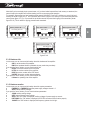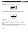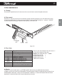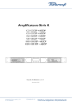
1
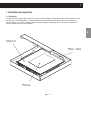
E
K20 - K10 - K8 - K6 - K4 - K3
Digital Audio Amplifier
for Professional Applications
User Manual
V1.14 (12-5-2009)
- K2
This page left intentionally blank
1
Table of contents
Important safety instructions ................................................................................................................................2
Approvals ................................................................................................................................................................3
Warning Notices...............................................................................................................................................................3
Safety rules.......................................................................................................................................................................4
Speaker damage..............................................................................................................................................................4
Speaker output shock hazard...........................................................................................................................................5
I ntroduction ......................................................................................................................................................................6
More sound and less weight.............................................................................................................................................6
Superior Sound-Sonic Accuracy.......................................................................................................................................6
Totally Digital with High Reliability........................................................................................................................................................6
The Best amplifier for Your Mains........................................................................................................................................................6
The K Series........................................................................................................................................................................................6
The Show Always Goes On..............................................................................................................................................6
Chapter 1: Installation and operation...........................................................................................................................................................7
1.1 Unpacking...................................................................................................................................................................7
1.2 Mounting.....................................................................................................................................................................8
1.3 Operating precautions................................................................................................................................................8
1.4 AC Mains connection..................................................................................................................................................8
1.5 Connecting Inputs........................................................................................................................................................9
1.6 Connecting Outputs.......................................................................................................................................................................10
1.7 Connecting Remote Control..........................................................................................................................................................11
1.8 AUX Input CH1/CH2.............................................................................................................................................................................................12
1.9 Alarm CH1/CH2....................................................................................................................................................................................................12
1.10 AES/EBU Input.....................................................................................................................................................................................................12
Chapter 2: Setup and settings.....................................................................................................................................................................13
2.1 Introduction....................................................................................................................................................................................13
2.2 The Main screen............................................................................................................................................................................13
2.3 The main menu............................................................................................................................................................................14
2.3.1 Output attenuation......................................................................................................................................................................15
2.3.2 Gain/Sensitivity.............................................................................................................................................................................15
2.3.3 Input select........................................................................................................................................................................16
2.3.4 Max output voltage............................................................................................................................................................16
2.3.5 Max mains current............................................................................................................................................................16
2.3.6 Clip limiter CH1-CH2........................................................................................................................................................16
2.3.7 Gate CH1-CH2.................................................................................................................................................................17
2.3.8 Mute at power on..............................................................................................................................................................17
2.3.9 Idle Mode..........................................................................................................................................................................17
2.3.10 DSP Settings...................................................................................................................................................................17
2.3.11 Ethhernet Settings...........................................................................................................................................................17
2.3.12 Bar meters......................................................................................................................................................................17
2.3.13 Output meters.................................................................................................................................................................17
2.3.14 Temperature....................................................................................................................................................................18
2.3.15 Mains meters..................................................................................................................................................................18
2.3.16 Amplifier Name................................................................................................................................................................18
2.3.17 Local preset.....................................................................................................................................................................18
2.3.18 Hardware info.................................................................................................................................................................19
2.3.19 Hardware monitor...........................................................................................................................................................19
2.3.20 LCD contrast....................................................................................................................................................................20
2.3.21 Set Keylock code.............................................................................................................................................................20
2.3.22 Menu locking...................................................................................................................................................................20
2.3.23 Service............................................................................................................................................................................20
2.3.24 The Smartcard function..................................................................................................................................................21
Chapter 3: Protection.................................................................................................................................................................................22
3.1 Turn-On/Turn-Off muting..............................................................................................................................................................22
3.2 Short circuit protection.................................................................................................................................................................22
3.3 Thermal protection.......................................................................................................................................................................22
3.4 DC fault protection.......................................................................................................................................................................22
3.5 Input/Output protection................................................................................................................................................................22
Chapter 4: User maintenance....................................................................................................................................................................23
4.1 Cleaning.......................................................................................................................................................................................23
4.2 Dust removal........................................................................................................................................................................................23
4.3 Error codes................................................................................................................................................................................23
4.4 Service................................................................................................................................................................................23
Chapter 5: Warranty...................................................................................................................................................................................24
Chapter 6: Assistance................................................................................................................................................................................24
Chapter 7: Technical notes........................................................................................................................................................................24
7.1 General Dimension..............................................................................................................................................................................24
7.2 Block diagram...............................................................................................................................................................25
7.3 Technical specifications...............................................................................................................................................................26
E
2
Important safety instructions
CAUTION
RISK OF ELECTRIC SHOCK
DO NOT OPEN
!
CAUTION: TO REDUCE THE RISK OF ELECTRIC SHOCK, DO NOT REMOVE THE COVER. NO USERSERVICEABLE PARTS INSIDE. REFER SERVICING TO QUALIFIED SERVICE PERSONNEL.
"WARNING: TO REDUCE THE RISK OF FIRE OR ELECTRIC SHOCK, DO NOT EXPOSE THIS APPARATUS TO
RAIN OR MOISTURE AND OBJECTS FILLED WITH LIQUIDS, SUCH AS VASES, SHOULD NOT BE PLACED ON
THIS APPARATUS"
"TO COMPLETELY DISCONNECT THIS APPARATUS FROM THE AC MAINS, DISCONNECT THE POWER
SUPPLY CORD PLUG FROM THE AC RECEPTACLE"
"THE MAINS PLUG OF THE POWER SUPPLY CORD SHALL REMAIN READILY ACCESSIBLE"
SAFEGUARDS: Electrical energy can perform many useful functions. This unit has been engineered and
manufactured to assure your personal safety. Improper use can result in potential electrical shock or fire
hazards. In order not to defeat the safeguards, observe the following instructions for its installation, use and
servicing.
!
!
!
!
!
!
!
!
!
!
!
!
Read these instructions.
Keep these instructions.
Heed all warnings.
Follow all instructions.
Do not use this apparatus near water.
Clean only with dry cloth.
Do not block any ventilation openings. Install in accordance with the manufacturer's instructions.
Do not install near any heat sources such as radiators, heat registers, stoves, or other apparatus
(including amplifiers) that produce heat.
Do not defeat the safety purpose of the polarized or grounding-type plug. A polarized plug has two
blades with one wider than the other. A grounding type plug has two blades and a third grounding
prong. The wide blade or the third prong are provided for your safety. If the provided plug does not fit
into your outlet, consult an electrician for replacement of the obsolete outlet(*).
Protect the power cord from being walked on or pinched particularly at plugs, convenience
receptacles, and the point where they exit from the apparatus.
Only use attachments/accessories specified by the manufacturer.
Unplug this apparatus during lightning storms or when unused for long periods of time.Refer all
servicing to qualified service personnel. Servicing is required when the apparatus has been damaged
in any way, such as power-supply cord or plug is damaged, liquid has been spilled or objects have
fallen into the apparatus, the apparatus has been exposed to rain or moisture, does not operate
normally, or has been dropped.
EXPLANATIONS OF GRAPHICAL SYMBOLS:
Lightning Flash Symbol, with "The Lightning Flash with arrowhead symbol within an equilateral
!
triangle, is intended to alert the user to the presence of uninsulated "dangerous voltage" within the
product enclosure that may be of sufficient magnitude to constitute a risk of shock to persons".
!
Exclamation Point Symbol, with "The exclamation point within an equilateral triangle is intended to
alert the user to the presence of important operating and maintenance (servicing) instructions in the
literature accompanying the product".
(*) for K2 and K3 only. K4, K6, K8, K10 and K20 comes with a special mains cable without plugs.
3
Approvals
The Digam K series is installed according to the Canadian Electrical Code or National Electrical Code, as applicable.
Install this product in accordance with Canadian Electrical Code or National Electrical Code and other local
electrical or building codes as applicable. Mount in rack only. The flexible mains cable must not pass through
walls
K10 - K8 - K6 - K4
This equipment has been tested and found to compliant by Competent Body (Directive 89/336/EEC-EMC) pursuant to the
product family standard for audio professional use:
EN 55103-1 and EN 55103-2 standard ); EN61000- 3 - 2 , EN 61000 - 3 - 3.
Conducted Emissions
: Electromagnetic Ambient E1, E2, E3 / Class B
Radiated Emissions
: Electromagnetic Ambient E1, E2, E3 / Class B
In a domestic environment this product may cause radio interferences in which case the user may be required to take
adequate measures.
This equipment has been tested and found to comply by Notified Body (Directive 2006/95/EEC L.V) pursuant to the audio
apparatus safety requirements: Standard EN 60065.
K3 - K2(*)
This equipment has been tested and found to compliant by Competent Body (Directive 89/336/EEC-EMC) pursuant to the
product family standard for audio professional use:
EN 55103-1 and EN 55103-2 standard ); EN61000- 3 - 2 , EN 61000 - 3 - 3.
Conducted Emissions
: Electromagnetic Ambient E1, E2, E3 / Class B
Radiated Emissions
: Electromagnetic Ambient E4, E5 / Class A
Radiated Emissions
: Electromagnetic Ambient E1, E2, E3 / Class B (**)
In a domestic environment this product may cause radio interferences in which case the user may be required to take
adequate measures.
(**) Additional round snap ferrite (of at least 145 Ohm @ 25 Mhz and 265 Ohm @ 100MHz) on Output cables and Mains
Cord allows to fulfill Electromagnetic Ambient E1, E2, E3 / Class B on radiate Emissions.
This equipment has been tested and found to comply by Notified Body (Directive 2006/95/EEC L.V) pursuant to the audio
apparatus safety requirements: Standard EN 60065.
K20
This equipment has been tested and found to compliant by Competent Body (Directive 89/336/EEC-EMC) pursuant to the
product family standard for audio professional use:
EN 55103-1 and EN 55103-2 standard ); EN61000- 3 - 2 , EN 61000 - 3 - 3.
Conducted Emissions
: Electromagnetic Ambient E4, E5 / Class A
Radiated Emissions
: Electromagnetic Ambient E4, E5 / Class A
In a domestic environment this product may cause radio interferences in which case the user may be required to take
adequate measures.
This equipment has been tested and found to comply by Notified Body (Directive 2006/95/EEC L.V) pursuant to the
audioapparatus safety requirements: Standard EN 60065.
(*) K2 and K3 pending
Warning notices
LOCATION: Install the amplifier in a well-ventilated location where it will not be exposed to high temperature or humidity.
Do not install the amplifier in a location that is exposed to direct rays of the sun, or near to hot appliances or radiators.
Excessive heat can adversely affect the cabinet and internal components. Installation of the amplifier in a damp or dusty
environment may result in malfunction or accident.
E
4
Precautions regarding installation
Placing and using the amplifier for long periods on heat-generation sources will affect performances. Avoid placing the
amplifier on heat-generating sources. Install this amplifier as far as possible from tuners and TV sets. An amplifier
installed in close proximity to such equipment may cause noise or degradation of the picture.
WARNING: To prevent fire or electric shock:
!
!
!
The ventilation should not be impeded by covering the ventilation openings with items such newspapers,
table-clothes, curtains etc.
Do not expose this equipment to rain or moisture.
Apparatus shall not be exposed to dripping or splashing and no objects filled with liquids, such as vases, shall
be placed on the apparatus”.
Safety Rules
This device must be powered exclusively by earth connected mains sockets in electrical networks compliant to the IEC
364 or similar rules.
Is absolutely necessary to verify this fundamental requirement of safety and, in case of doubt, require an accurate
check by a qualified personnel.
The constructor cannot be considered responsible for eventual damages caused to persons, things or data for the
missing of accurate earth link.
Before powering this device verify that the amplifier is supplied with the correct voltage rating.
!
Verify that your mains connection is capable to satisfy the power ratings of the device.
!
Do not spill water or other liquids into or on the unit.
!
Do not use this unit if the electrical power cord is frayed or broken.
!
Do not remove the cover. Removing the cover will expose you to potentially dangerous voltage.
!
No naked flame sources such like lighted candles should be placed on the amplifier.
!
Provide sectioning breaker between mains connections and apparatus. Suggested device is 32A/250Vac, C or
!
D curve, 10KA
!
Caution: to completely disconnect this apparatus from the ac mains disconnect the power supply cord from
the rear panel ac socket.
The power cord type is LAPP CABLE OLFLEX191 3G6 / SJT 3XAWG10 SALCAVI (Bahoing SJT 3x16AWG or
!
I-sheng SGIS 3G1,5mmq for K3 - K2)
Speaker damage
The DIGAM series amplifiers are among the most powerful professional amplifiers available and are capable of
producing much more power than many loudspeakers can handle. It is the user's responsibility to use suitable
speakers with the amplifier and to use them in a sensible way that will not cause damage. Powersoft will not be
responsible for damaged speakers. Consult the speaker manufacturer for power-handling recommendations. Even if
you reduce the gain using the amplifier's front panel attenuation controls, it is still possible to reach full output power if
the input signal level is high enough.
A single high-power crescendo can damage high-frequency drivers almost instantaneously, while low-frequency drivers
can usually withstand very high, continuous power levels for a few seconds before they fail. Reduce power immediately
if you hear any speaker "bottoming out" - harsh pops or cracking distortion that indicate that the speaker voice coil or
diaphragm is striking the magnet assembly. Powersoft recommends that you use amplifiers of this power range for
more headroom (cleaner sound) rather than for increased volume.
E
5
Speaker output shock hazard
A DIGAM amplifier is capable of producing hazardous output voltages. To avoid electrical shock, do not touch any exposed
speaker wiring while the amplifier is operating.
This manual contains important information on operating your DIGAM amplifier correctly and
safely. Please read it carefully before operating your amplifier. If you have any questions,
contact your Powersoft dealer.
E
6
Introduction
Powersoft is a leading company in the field of high efficiency audio power management. The totally new Powersoft's
DIGAM (DIGital AMplifier) technology has changed the way the world looks at professional audio amplification. No
other amplifiers come close for applications demanding high power and long term reliability. Thanks to amazing
reductions in heat output along with reductions in weight and the specific high output power, DIGAM amplifiers can be
used in an unlimited range of applications such as concert touring, opera houses, theatres, churches, cinema, theme
parks, television sound stages and industrial applications.
More sound and less weight
Compared to a conventional amplifier, Powersoft DIGAM technology offers very high efficiency and delivers more
power to the loudspeakers with much reduced heat dissipation. This greater efficiency enables dimensions, weight and
power consumption to be reduced. The output stages of the amplifiers typically run at 95% efficiency, dissipating only
5% of the input energy as heat.
One of the most interesting characteristics is that DIGAM's efficiency is almost independent of output level.
Conventional amplifiers achieve their best efficiency only at full rated power output. Since standard music has an
average power density of 40% of the maximum level, conventional amplifiers can easily generate 10 times more heat
than DIGAM for the same volume of sound.
Superior Sound-Sonic Accuracy
Crystal-clear highs, and a tight, well-defined low end: the most accurate reproduction of an audio signal. Patented
design features ensure very high performance in parameters such as distortion, frequency response, slew rate, power
bandwidth and dumping factor.
Totally Digital with High Reliability
The DIGAM series is based on PWM technology that has been used for 30 years or more in power supplies and
inverters. PWM provides high reliability, small size, low weight and high efficiency. A PWM converter works as a high
frequency sampler, converting the variable amplitude (audio) signal into an impulse sequence with average value
equal to the audio input.
DIGAM amplifiers use very high sampling frequencies to obtain high performances across the audio band. Powersoft
holds several patents on the DIGAM technology.
The Best Amplifier for Your Mains
Powersoft is the first amplifier manufactor that adopt Power Factor Correction. This unique feature ensures that a
predominantly resistive load is presented to mains, minimizing current distortion and voltage/current displacement
This leads to much improved performance of the amplifier at high levels of output and avoids mains-voltage collapses,
typical of standard and switching power supplies. Another great advantage of this technology is that its performance is,
to a large extent, independent of mains voltage. The rated output power does not vary with load/line conditions.
The K Series
K Series has many advanced features, Digital control of many parameters, adjustable maximum mains consuption,
selectable digital presets and a graphic display that shows detailed information of the status of the amplifier. You can
appreciate the functionality of these and a lot of other features by reading this manual carefully.
The Show Always Goes On
DIGAM Series is completely protected against every possible error in operation and is designed to work under every
condition. It gives you maximum power with maximum safety and increases long-term reliability. Anticipating potential
problems at the design stage means your show always goes on!
E
7
1 Installation and operation
1.1 Unpacking
Carefully open the shipping carton and check for any noticeable damage; the figure below shows the exploded view of the
packing. Every Powersoft amplifier is completely tested and inspected before leaving the factory and should arrive in
perfect condition. If you find any damage, notify the shipping company immediately. Be sure to save the carton and all
packing materials for the carrier's inspection.
E
Amplifier
Mains cable
Manual
figure 1.1
8
1.2 Mounting
All DIGAM amplifiers are previewed for the standard 19" rack mounting; there are four front panels holes and fout rear
lateral holes. The amplifiers must be fixed into rack in both sides, back and frontal, to avoid mechanical damages. Your
DIGAM amplifier uses a forced-air cooling system to maintain a low, even operating temperature. Drawn by an internal
fan, air enters through the slots in the front panel and courses over and through components. The DIGAM series
amplifiers feature an "intelligent" variable-speed DC fan which is controlled by heat sink temperature sensing circuits:
the fan speed will increase only when the temperature of either heat sink requires it, which keeps fan noise to a
minimum and helps cut dust accumulation inside. Under extreme thermal load, the fan will force a very large volume of
air through the heat sinks. If either heat sink gets too hot, its sensing circuit will reduce the output power. If the
amplifier overheats, another sensing circuit shuts down its circuit to cut off power until it cools to a safe temperature.
The exhaust cooling air is forced out through the rear of the chassis (see figure 1.2.1), so make sure there is enough
space around the sides of the amplifier to allow the air to escape. If it is rack mounted, make sure the exhaust air can
flow without resistance. If you are using a rack with closed backs, there must be at least one standard rack space of
opening in the front of the rack for every four amplifiers. Amplifiers may be stacked directly on top of each other (no
space needed between units), starting from the bottom of the rack.
air flow
figure 1.2.1
1.3 Operating Precautions
Make sure the AC mains voltage is correct and is the same as that printed on the rear of the amplifier. Damage caused
by connecting the amplifier to improper AC voltage is not covered by the warranty. Make sure the power switch is off
before making any input or output connections.
It is always a good idea to have the gain controls muted during power-up to prevent speaker damage if there is a high
signal level at the inputs.
Whether you buy them or make them, use good-quality input and speaker cables. Most intermittent problems are
caused by faulty cables. Use good-quality connectors and wire, along with good soldering technique, to ensure
troublefree reliability.
1.4 AC Mains connection
The AC Main connection is made via the CPC type connector (IEC20A for K3 and K2) on the rear side of the panel.
The figure below shows the connection to the amplifier. Be sure that your AC mains power source has the
requirements indicated in this manual.The DIGAM amplifier has an automatic power factor correction system for a
perfect mains network interface. The amplifier is a resistive load for the mains network, minimizing the reactive power
and the harmonic distortion on the current. The system allows performance to be maintained even in circumstances of
varying the mains voltage. Is important to connect the ground for safety, do not use adapters that disable the
ground.
CAUTION! RISK OF ELECTRIC SHOCK: DO NOT OPEN
TURN
Digam K3, K2 only
TO LOC
K
open the lock
and insert the plug
lock the plug
MAINS
GROUND
other K models
MAINS
Vac
figure 1.4.1
GND
E
9
1.5 Connecting Inputs. Input connections are made via the 3-pin XLR-female type or 1/4" phone Jack connectors on the
L
IN2
OUT2
LINK ON OFF
TURN T
O
L
K
OC
K
OC
CLASS2 WIRING
TURN T
O
OUT1
IN1
“WARNING
To reduce The Risk of Fire
or Electric Shock, do not
Expose this Apparatus
to Rain or Moisture”
rear side of the amplifier. The polarity is shown in figure 1.5.1.
pin2 - IN(+)
pin1 - GND
pin3 - IN(-)
IN(-)
IN(+)
E
GND
figure 1.5.1
The figure below shows the connection of analog input for balanced and unbalanced line. You can use both configuration,
but you must consider that unbalanced long line can introduce noise in the audio system. The Link switch located in the
rear panel is for direct paralleling the rear input connectors. You can use the remaining input connector to carry signal to
other amps.
GND
SHIELD
IN(+)
IN(-)
IN(+)
/
Unbalanced input
Balanced input
figure 1.5.2
For K3, K2 and K3I, K2I the input connections are showed in the figure below; analog input for balanced and unbalanced
line is also available for this models. Input connections for K3I, K2I are made the 3-pin Phoenix Contact MC 1,5/ 3-ST-3,81.
K3 - K2
model
pin1 - GND
XLR female
pin2 - IN(+)
pin3 - IN(-)
pin 2 - IN(+)
signal source input
XLR female connector
signal source output
XLR male connector pin1 - GND
XLR male
pin 3 - IN(-)
Phoenix Contact
MC 1,5/ 3-ST-3,81
K3I - K2I
model
IN(+)
figure 1.5.3
GND
IN(-)
10
1.6 Connecting Outputs
L
IN2
OUT2
LINK ON OFF
TURN T
O
L
K
OC
K
OC
CLASS2 WIRING
TURN T
O
OUT1
IN1
“WARNING
To reduce The Risk of Fire
or Electric Shock, do not
Expose this Apparatus
to Rain or Moisture”
Warning: there are lethal voltages at the loudspeaker connectors when the amplifier is turned on. To prevent any
damages turn the amplifier off before connecting the loudspeaker
Output connectors are made via neutrik speakon connectors. Consult the wire gauge chart to find a suitable wire gauge to
minimize power and damping factor losses in the speaker cables. The outputs can also work on bridge mode. For each
device the 1+ and 2+ pins of speakon connector are connected inside and have to be considered the positive output of the
channel; the 1- and 2- pins of speakon connector are connected inside and have to be considered the negative output of
the channel.
Note: Channel B is always polarity reversed output stage, but polarity compensated by feeding the minus pins of the
channel B output with the output voltage. Channel A is connected in the polarity mode. By having channel A and B
operating in opposite polarity, the energy storage in the power supply is more efficient. This is significant for signals below
100Hz (sub bass etc.) and improves the power bandwidth. Be sure to use balanced inputs on all measurement
equipment (also oscilloscope probes) in you are bench testing.
2+
2+
1-
2-
+
2-
_
_
1+
CH1
OUT
1+
stereo mode
2+
+
12-
_
1+
CH1
OUT
+
1-
CH2
OUT
2+
121+
bridge mode
CH2
OUT
figure 1.6.1
K3I and K2I model requires Phoenix Contacts GMSTB 2,5/ 2-ST connectors for output connections, the polarity is showed
in the figure below. In K3I stereo end bridge mode output follow wiring show on figure 1.6.1.
Phoenix Contacts
GMSTB 2,5/ 2-ST
K3I - K2I
model only
OUT (-)
figure 1.6.2
OUT (+)
11
1.7 Connecting Remote Control
You can control the amplifier via a RS485; The figure 1.7.1 shows the connection of the data cable to the plug located to the
rear panel of the amplifier. connection. The same figure shows also the ID selection for Remote Control (in this case ID=
28); to change the ID, rotate the selectors at the desired value. The selected ID value also is shown in Hardware info
section ( see par 2.3.18 ).
E
remote
connection
cable
8 pin
modular
plug
E
Pin Layout
Vext 485+
GND 485figure 1.7.1
ID selection example
ID = 28
12
1.8 AUX Input CH1/CH2 (K2I and K3I only)
These inputs are automatically selected in place of the line input CH1/CH2 when an external voltage of 24V DC is applied
through the AUX COMMAND input, these inputs can be used for emergency signals as pre-recorded evacuation messages
or similar alarm messages.
1.9 Alarm CH1/CH2 (K2I and K3I only)
Relays output 24V outputs to command external equipment; alarm relays output normally closed, open for reporting
amplifier faults
1.10 AES/EBU Input
On DSP equipped amplifiers CH2 is the AES/EBU input when the AES/EBU pushbutton is released (see the figure 1.101);
in this mode, if an analog input in CH2 is applied, the ANALOG CH2 OUT is off; if CH2 is used as analog input the
AES/EBU pushbutton must be pressed. K3I and K2I have dedicated AES/EBU input and auxiliary input on two Phoenix
connectors (see figure 1.10.2).
AES/EBU pushbutton:
pressed - analog input
released - AES/EBU input
figure 1.10.1
K3I - K2I
model only
dedicated
AES/EBU inputs
figure 1.10.2
13
2 Setup and settings
2.1 Introduction
The figure below shows the front panel of DIGAM K Series. The front panel controls, in conjuction with the graphic
LCD display above the buttons, give to the user the total control and detailed information about the status of the
amplifier. Each pushbutton has multiple functions and the display shows the current active function for each button.
Read carefully the instructions below that help you to manage the functions of the amplifier.
E
LA B
A - Ethernet plug n° 1
B - Ethernet plug n° 2
C - V/I-meter channel n° 1
D - Smartcard reader
E - Function button n° 1
F - Function button n° 2
C DE F G H I J
KL
G - Function button n° 3
H - Function button n° 4
I - Graphic LCD display
J - V/I meter channel n° 2
K - Power switch
L - Grill filter screws
figure 2.1.1
2.2 The main screen
The figure 2.2.1 show the main screen; this screen appears after a short presentation when the user powers on the
amplifier. In the first line, after power on, the writing "WAIT" appears; if the system parameters are normal, the writing
are replaced with "READY". During the normal operation the controller monitors the system parameters. If a
paramenter is out of range, the correspondent code error is written on the LCD meter of the relative channel in the
third line; if the abnormal parameter is associated to both channel, the error code is written in the center.
CH1 READY READY CH2
I
I V
V
lock mute mute menu
figure 2.2.1
The LED bars can function as output voltage or output current meters; in the first case the LCD meters function as
output current meter, viceversa in the second case. The first green LED at the bottom side of the LED bar indicates,
when lighted, the presence of input audio signal above -60 dBV on the corresponding channel; the 2nd, 3rd and 4th
LED in the ascending order indicates an output level of -3dB, -6dB and -10dB rispectively. The green LEDs will be
lighted during normal working. The yellow LED will light at -1 dB. If the level of the audio signal reach the channel
output capability, red LED will be triggered.
The LED bars have diagnostic function also; a flashing yellow LED indicates a critic range of temperature (from 80°C
to 85°C)of the power devices on the corresponding channel, if this LED is lighting constantly, the temperature is above
85°C. A lighting constantly red LED indicates that the corresponding channel is under protection and in this case the
writing "PROT" appears in the first line of the display.
14
The fourth line of the screen shows the functions of the buttons below.
The "lock" function is activated if the corresponding button is pressed more than 1 second; in this case all the other buttons
are locked. The same operation unlocks these buttons (unlock code is required - see par. 2.3.17 for more details).
The "mute" buttons switch off the two channels independently; in this case the parameters of the correspondent channel
disappear and the writing "muted" appears on the third line. The same operation disables the mute function.
If the "menu" button is pressed, the main menu is displayed on the LCD screen.
2.3 The main menu
The figure 2.3.1 shows the main menu. You can scroll the menu items by pushing the up or down buttons and choose the
selected one by pushing "ok" (if the chosen item enables or disables a function, the writing "on" is replaced with "off" for
disabling it, or "on" for enabling it. The menu tree is shown in figure 2.3.2.
Settings
Display
Local Preset
back
menu
figure 2.3.1
menu
Settings
Amplifier Settings
Output attenuation
Input gain/sens
Input select
Max output voltage
Max mains current
Clip limiter CH1
Clip limiter CH2
Gate CH1
Gate CH2
Mute at Power on
Idle Mode
DSP Settings (or not present) *
Network Settings (or not present) **
Display
Bar meters
Output meters
Temperature
Mains meters
Amplifier Name
Local presets
Setup
Recall local preset
Save local preset
Hardware info
Hardware monitor
LCD contrast
Set Keylock code
Menu locking
Service
* Available only with optional DSP board
** Available only with optional KAESOP board
figure 2.3.2
Analog=>Out
Analog=>DSP=>Out *
AES3=>Out *
AES3=>DSP=>Out *
KAESOP=>Out **
KAESOP=>DSP=>Out * **
15
To better handle the huge amount of parameters, the single value numeric input mode is extended with a fine/coarse
feature. When you edit one of the parameters, you will start in the “fine” mode. The steps applied by the - and + keys
are the minimum allowable for that parameter. By clicking the “fast” key shown in figure 2.3.3, you will switch in the
“coarse” mode, and the key will be renamed as “slow” as shown in figure 2.3.4 . In the coarse mode, the steps are
equivalent to 10 steps of the fine mode, so that editing will be 10 times faster. Remember that by keeping the - or +
key pressed, the steps are automatically repeated.
Max mains current
22 A rms
back
+
-
Max mains current
22 A rms
back
fast
-
figure 2.3.3
+
slow
figure 2.3.4
2.3.1 Output attenuation
The figure 2.3.5 shows the Output attenuation screen. You can choose to set CH1, CH2 or both by pushing the "C1+2"
button. The "+" and "-" buttons change the value of the output attenuation in the range from 0 to -30dB.
Note: for the best sonic performance it is preferred to set the 0db output attenuation (no attenuation), and
select the proper gain/sensitivity by the following menu.
Output attenuation
-13
dB -13
back
-
+
C1+2
figure 2.3.5
2.3.2 Gain/Sensitivity
The figure 2.3.6 shows the Gain/Sensitivity screen. You can choose to set CH1, CH2 or both by pushing "C1+2"
button. The "+" and "-" buttons change the value of the gain. The values of gains permitted are 26, 29, 32 and 35 dB;
the corresponding values of sensitivity and maximum input voltage are written in the table below.
Gain/Sensitivity
dB
29
29
3.62 Vrms 3.62
+ C1+2
back -
figure 2.3.6
MODEL
GAIN
K2
K3
K4
K6
K8
K10 K20
26
4.46 5.29 4.16 5.10 5.50 6.32 6.95
29
3.15 3.76 2.96 3.62 3.90 4.45 4.90
32
2.23 2.66 2.10 2.55 2.75 3.16 3.48
35
1.58 1.88 1.48 1.81 1.96 2.23 2.46
values of sensitivity (Vrms)
GAIN
26
29
32
35
ACCEPTANCE
dBV
dBu Vrms
18
25.0
27
12
21.6
24
9
19.0
21
6
15.6
18
values of maximum balanced input
E
16
2.3.3 Input select
You can choose among three different input modes (if available): Analog, Digital AS3* with or without DSP processing and
Ethernet**. The up and down buttons change the selection; the "sel" button locks the selected option.
* Available only with optional DSP board
** Available only with optional KAESOPboard
2.3.4 Max output voltage
The figure 2.3.7 shows the Max output voltage screen. You can choose to set CH1, CH2 or both by pushing "C1+2"
button. The "+" and "-" buttons change the value of the max output peak voltage. The ranges available are showed in the
table below
Max output voltage
102 Vpeak 102
back
-
+
C1+2
figure 2.3.7
MODEL
K2
K3
K20
K4
K6
K8
K10
40 to 140 40 to 165 40 to 125 40 to 153 40 to 169 40 to 200 40 to 225
Values of peak voltage (V)
2.3.5 Max mains current
The figure 2.3.8 shows the Max mains current screen. The "+" and "-" buttons change the value of the max mains current
input in the range from 15 to 32A (8 to 16A for K3, K3I, K2 and K2I). Maximum mains current limit set the rms value at
which a C-Type current breaker will trip-off.
Max mains current
22 A rms
back
-
+
fast
figure 2.3.8
2.3.6 Clip limiter CH1 - CH2
Enable this function to prevent the distortion due to excessive amplitude of output signal. You can enable/disable it by
pushing the on/off button.
CAUTION: There is the risk of damage to the loudspeakers, if Clip Limiters are deactivated. You should not
deactivate Clip Limiters unless their function is taken over by external devices, such as digital system controllers.
In such cases it is mandatory, to properly adjust parameters in the external device.
12
17
2.3.7 Gate CH1 - CH2
This function allows to mute the amplifier channels individually if input signal amplitude is falling below the values shown in
the following table. You can enable/disable it by pushing the on/off button. Gating the output is delayed by 5 seconds after
input signal removal, and follows in reversed way the bottom green LED on the CH1, CH2 bar LED display *(muted if green
LED is off).
26
GAIN 29
(dB) 32
35
TRESHOLD VALUES OF INPUT SIGNAL DETECTOR
dBu
dBV
mVrms
-52
2
-54
-55
1,41
-57
-58
1
-60
-61
0,707
-63
2.3.8 Mute at power on
If enabled, the amplifier will be always in mute state for both channels at power on; you can mute off the channels
independently in the main screen, but in this mode the amplifier will be in the mute state at the next power on.
2.3.9 Idle Mode
The idle mode function is a power saving feature. By activating it, if the amplifier doesn't detect the signal for the user
defined amount of time, the output stage is turned off, saving about 40 W of power per channel. This means reduced
heating, longer amplifier and fans life, and, especially for fixed installation permanently turned on, a lower electricity bill.
2.3.10 DSP Settings
This sections is implemented if optional DSP board is present.
2.3.11 Ethernet Settings
This sections is implemented if optional Ethernet board is present.
2.3.12 Bar meters
In the Bar meters screen you can choose if the LED bars operate as output voltage meter and LCD bar in the main screen
as output current meter (by selecting "LED Volt, LCD Curr), or viceversa (by selecting the other item).
2.3.13 Output meters
In the Output meters screen you can view the values of the output signal for CH1 and CH2. Furthermore, the impedance of
the load is showed in the bottom line of the screen (see figure 2.3.9). Minimum of output voltage for impedance
measurements is 10Vrms, measurements values are stored into logbook. Time between single impedance measurements
can be up to several minutes depending on program signal. Output power is shown as maximum value every 200 mS.
0 Vrms
0 Arms
0 Watt
back Zload=8.0 C1+2
figure 2.3.9
In "C1+2" mode the screen shows the output values in bridge connection.
E
18
2.3.14 Temperature
In the Temperature screen you can view the historic temperature diagram of the last four hours of the final current use in
the range from 10 to 90°C; in the bottom-right side of the screen there is the present value (see figure 2.3.10).
38°C
back
E
figure 2.3.10
2.3.15 Mains meters
In the Mains meters screen you can view the voltage and the current of the mains (see figure 2.3.11).
Mains meters
170 Vrms
20 Arms
back
figure 2.3.11
2.3.16 Amplifier Name
The amplifier name, together with the current preset name, can be displayed by enabling the “Display amplifier data”
function. The 20 characters amplifier name, together with the 40 characters preset name is shown in an different way when
the amplifier is in the starting page of the main menu. The amplifier name can be assigned by the “Edit amplifier name”
command (for the text editing, see Local preset handling section).
2.3.17 Local preset
There is the possibility to store up to 50 presets on amplifier local memory.
By choosing the Save local preset command, the current amplifier configuration (basic amplifier settings + KDSP board
settings if DSP board is present) is stored on the local memory. To proceed, the menu asks to choose one of the 50
available presets (see figure 2.3.12), showing the preset number and name. If the preset was never used, it is named
<empty>. By pressing ok, you can enter the preset name. The selected character is pointed by the arrow shown in
Figure 2.3.13, and by pressing or + keys it is modified. By pressing sel key, next character is selected as shown in figure
2.3.14. When the name input is finished, by pressing the ok key, the preset is stored
Select preset #1
<empty>
back
<-
->
figure 2.3.12
ok
Choose preset name
PRESET 1
^
sel
back +
figure 2.3.13
Choose preset name
18 SET 1
^
sel
back +
figure 2.3.14
The Recall local preset command loads and applies one of the stored presets, choosen through an identical dialog. Please
note that all the current amplifier settings are overwritten!
14
19
Note that if you have already input a preset name, or if you have loaded a preset from local memory or smartcard, the
name is kept by the amplifier and used as starting point for a new save preset operation.
For example, suppose that you have loaded a preset named “18IN SUB 1” from a SC, and then you save it into local
memory as shown in figure 2.3.15. In this case the menu shown in figure 2.3.16 asks you if you want to keep/edit that
name (shown figure 2.3.17) or if you would like to edit the name of the preset that is going to be overwritten (shown
figure 2.3.18). This is useful for copying presets from/to smartcard.
Select preset #3
Existing Preset
back
<-
->
Keep this name?
18IN SUB 1
ok
figure 2.3.15
no
back
-
+
yes
Choose preset name
18IN SUB 1
^
sel
back
ok
+
figure 2.3.16
Choose preset name
Existing Pre
^
sel
ok
back
+
figure 2.3.18
2.3.18 Hardware info
In this screen you can view some information about the hardware of the amplifier:
S/N the serial number of the amplifier
!
HW ID the hardware identifier (selectable by rear panel rotary encoders)
!
if you push the "more" button, you can view the other info
KFRNT the version number of the front panel
!
KCTRL the version number of the controller
!
KDSP the version number of the DSP board
!
KAESOP the version number ethernet adapter
!
if you push the "more" button, you can view the other info
Lifetime the operating time of the amplifier
!
2.3.19 Hardware monitor
In this screen you can view some information about the system parameters:
!
PWRBSCH1 - PWRBSCH2 amplifier power supply voltages channel 1-2
!
VAUX internal auxiliary voltages
if you push the "more" button, you can view the others parameters:
!
+5VAN auxiliary analog voltage
!
VEXT external remote control voltage
!
VAUX if the "OK" written is displayed, auxiliary voltages of power supply are correct.
!
IGBTCONV if the "OK" written is displayed, the DC/DC converter monitor function properly
!
192KHZ if the "OK" written is displayed, the frequency system clock is right
figure 2.3.17
E
20
15
2.3.20 LCD contrast
In this screen you can set the contrast of the LCD display by pushing the +/- buttons (see figure 2.3.19).
Contrast
6
back
-
+
figure 2.3.19
2.3.21 Set keylock code
In this screen you can insert the numeric key to unlock the settings; the same screen appears when the "unlock" button in
the main screen is pressed. There is a universal key to unlock the settings: this is 270156.
Set keylock Code
000000
back
^
-
+
sel
figure 2.3.20
2.3.22 Menu locking
In addition to the basic pushbutton locking function, a new menu locking strategy was introduced. There are three levels of
locking: All locked, Allow safe, Allow all.
All locked: only the menus for displaying infos are enabled, the other are hidden. Presets cannot be loaded.
Allow safe: user can change from Analog input to AES3 input, always with DSP into the signal path. Some common DSP
parameters can be changed (AES3 gain trim, main delay, DSP input selection)*. Only local presets can be recalled, and
they should be all safe for the speaker system connected to that amplifier (example: HF driver 3 dB, HF driver 0 dB, HF
driver +3 dB).
Allow all: all settings menus are enabled. User can recall presets from either local memory or smartcard.
Furthermore, local presets can be made Read-Only by enabling the “Lock presets” function, in order to preserve the original
settings stored on the amplifier.
The lock code, when set different from 000000, protects the whole Menu locking submenu.
* Available only with optional DSP board
2.3.23 Service
The key to activate this function is factory reserved.
14
21
2.3.24 The Smartcard function
There is the possibility to store up to 150 presets for each settings smartcard (shown figure 2.3.21). The menu is
activated when the smartcard is inserted in the amplifier, only if the main page of the menu is selected. The store and
recall procedures are identical to those used for local presetsas shown in figure 2.3.22.
E
contacs on the
bottom side
figure 2.3.21
Recall local preset
Save local preset
back
ok
figure 2.3.22
You can select the desired option by pushing up or down button and "ok" to activate it. The option "Recall local preset”
does not appear if the smartcard is blank.
22
15
3 Protection
3.1 Turn-On/Turn-Off muting
For about four seconds after turn-on, and immediately at turn-off, the amplifier outputs are muted.
3.2 Short circuit protection
A short circuit protection system safeguards the amplifier's output transistors under short circuits and other stressful loads.
It is completely inaudible when inactive. In case of short circuit, the red LED will be light-up and writing "PROT" appears in
the first line of the display(see Par. 2.2 for a detailed description). The amplifier will reset himself 50 times every 2 seconds.
Once 50 resets have been performed and the fault still exist on the output, the unit sets into steady protection mode. Turn
ON/OFF cycle is needed to restart the unit.
3.3 Thermal protection
A DIGAM amplifier uses a continuously variable speed fan to assist cooling (the fan speed changes in response to the
amplifier's cooling needs). If the heat sink temperature reaches approximately 80°C, the yellow LED starts to flashing. If the
temperature is more then 85°C the thermal sensing circuitry will mute each power section channels, the LED will light
permanently and the power supply will be cut off. Once the heatsink has cooled down, the amplifier will automatically reset
and the LED will be go out. It is possible to reduce the temperature by reducing the output power.
3.4 DC fault protection
If DC or excessive subsonic energy appears at a channel output, an instantaneous protection circuit will cut off the power
supply for both channels. Power supply shutdown is used instead of speaker relays, thereby improving the damping factor
and reliability of the DIGAM amplifiers.
3.5 Input/Output protection
An ultrasonic network decouples RF from the outputs and keeps the amplifier stable with reactive loads.
16
23
4 User maintenance
4.1 Cleaning
Disconnect the amplifier from the AC main source first; use a soft cloth to clean the faceplate and chassis.
4.2 Dust removal
Especially in a dusty environment, the front side filters clog with dust after prolonged use, this will interfere with cooling.
You may use compressed air to remove the dust from filters. To remove air filters see fig(3.4.1) , unscrew n° 2 M2,5X8
screw and rotate the covering grill; repeat the same operation on the other side.
coverage
grill
screw
filter
figure 4.3.1
4.3 Error Codes
Error code
1
2
4
8
100
200
2000
4000
8000
Error descr.
192KHz clock not present
Positive 15V aux
Negative 15V aux
Positive 5V analog
Negative power bus Ch1
Negative power bus Ch2
Positive power bus Ch1
Positive power bus Ch2
External auxiliary voltage
Check rail fuses Check rail fuses Ch1 and Ch2
The error code value displayed in the main screen is
the sum of the single error code value.
Example: 4301=4000+200+100+1 means
+
Positive power bus Ch2
+
Negative power bus Ch2
+
Negative power bus Ch1
192KHz clock not present
4.4 Service
There are no user-serviceable parts in your DIGAM amplifier. Refer servicing to qualified technical personnel.
In addition to having an in-house service department, Powersoft supports a network of authorized service centers. If your
DIGAM amplifier needs repair, contact your Powersoft dealer or distributor, or contact the Powersoft Technical Service
department, to obtain the location of the nearest authorized service center.
E
24
5 Warranty
Powersoft prides itself on the quality and reliability of its products that are designed and manufactured to meet the highest
quality standards. We are also proud of the great care we assure to our customers. We are confident that you will never
have a need to take advantage of this warranty, but in the unlikely event of a failure or deviation in performance, we'll do
our very best to get you swiftly back in business.
Powersoft amplifiers warranty is calculated from the original date of purchase from an Authorized Powersoft Dealer. During
this time, if your amplifier fails for any defect in components and/or labour under a correct and regular use, it will be
repaired or, at our sole opinion, replaced without any charge a part for the transport expenses to return the unit at
Powersoft premises. The repaired/replaced amplifier will be finally returned to you with the original shipping carton at our
charge.
The Warranty conditions will not be applied in case the amplifier has been ulteriorly damaged by repair attemps,
inadequate or poor packaging, any kind of improper use/maintenance (overvoltage, incorrect connection, use with wrong
or faulty associated equipment or accessories, exposure to rigid weather conditions, excess moisture, etc…).
Warranty terms will not be consider for any unit where the serial number has been removed and or it is not clearly
readable. Powersoft is not responsible for any incidental or consequential damages; the responsibility is limited to the
product itself. Powersoft reserves the right to make changes or improvements in design or manufacturing without
assuming any obligation to change or improve product previously manufactured.
6 Assistance
The local Powersoft distributor/reseller will be glad to support you in case of fault or for any additional information.
If you cannot contact your local distributor/reseller, please mail to [email protected]
Do not ship any unit to Powersoft for Factory Service before having had the Powersoft authorization.
7 Technical notes
16 6
7.1 General Dimension
456
(K3-338)
497
(K3-380)
466
(K3-348)
25
440
44.5
465
6.25
32
8
483 (19")
25
7.2 Block diagram
The figure 7.1.1 shows the the output stage block diagram, the figure 7.1.2 shows the power supply block diagram.
ETHERNET
CONNECTION
P
POWER RAIL
BUS +/-
P
DSP
OPTION
P
ETHERNET
OPTION
INPUT CH1
+
_
+
_
GAIN
SELECTION
P
DC DETECTOR
SHUTDOWN
FUSES
OUTPUT
ATTENUATOR
PATH
SELECTOR
OUTPUT MAX
VOLTAGE SELECTOR
OUTPUT CH1
OUPUT STAGE
(NOT INVERTING)
1+
2+
TO POWER
SUPPLY
21-
E
P
HF
LIMITER
INPUT
SIGNAL
DETECTOR
P
CLIP
LIMITER
OUPUT STAGE
CURRENT LIMITER
P
TEMPERATURE
CONTROL
P
POWER SUPPLY
CURRENT LIMITER
FROM
POWER SUPPLY
P
FAN
link
switch
ETHERNET
CONNECTION
P
P
DSP
OPTION
ETHERNET
OPTION
+
_
+
_
GAIN
SELECTION
INPUT CH2
P
DC DETECTOR
SHUTDOWN
FUSES
PATH
SELECTOR
OUTPUT
ATTENUATOR
TO POWER
SUPPLY
POWER RAIL
BUS +/-
OUTPUT MAX
VOLTAGE SELECTOR
OUTPUT CH2
OUPUT STAGE
(INVERTING)
1+
2+
21-
P
HF
LIMITER
INPUT
SIGNAL
DETECTOR
P
OUPUT STAGE
CURRENT LIMITER
CLIP
LIMITER
TEMPERATURE
CONTROL
P
FAN
POWER SUPPLY
CURRENT LIMITER
FROM
POWER SUPPLY
P
figure 7.1.1
SHUT DOWN
AUXILIARY
SUPPLY
Vboost OK
(TO P )
FUSES
MAINS
FILTER
P
MAINS
VOLTAGE
MONITOR
P
MAINS
CURRENT
MONITOR
BRIDGE
RECTIFIER
RESONANT
CONVERTER
CONTROLLER
PFC
CONTROLLER
POWER RAIL
BUS +/-
IGBT CONV OK
(TO P )
AUXILIARY
SUPPLY +
PFC
CONVERTER
RESONANT
CONVERTER
AUXILIARY
SUPPLY +
AUXILIARY
SUPPLY -
P (REMOTE ON/OFF)
FRONT
PANEL
SWITCH
Vaux OK
(TO P)
figure 7.1.2
TEMPERATURE
CONTROL
AUXILIARY
SUPPLY
OVERCURRENT
CONTROL
SHUT
DOWN
P
FAN
19
26
19
7.3 Technical specifications
POWER REQUIREMENTS
Power supply..............................................................................................................................115÷230V(-15%, +15%)
Power factor..........................................................................more than 0.95 (0.90 for K3 - K2) from 500W to full power
Operating temperature ................................……………...……..................................................................... 0° C, 45° C
Weight............................................................................................8Kg (17.6 lbs) for K3 - K2, 12Kg (26.5 lbs) all others
External dimensions.........................................Standard rack 19" (W), 1 Units (H), 497mm (D), 380mm (D) for K3 - K2
AUDIO SECTIONS
Bandwith (1W, 8Ohm)...................................................................................................................20Hz, 20KHz ±0,2 dB
Damping factor (8Ohm)......................................................................................................... ....(20Hz, 200Hz) > 5000
Slew Rate (8Ohm)............................................................................................................50V/uS (input filter bypassed)
S/N ratio....................................>110dB (K2),.>112dB (K3), >108 (K4), >108 (K6), >109 (K8), >110 (K10), >110 (K20)
Distortion THD…………………………………………………..... Max < 0.5% from 1W to full power (typically < 0.05%)
Intermodulation SMPTE …………………………..………...……. Max < 0.5% from 1W to full power (typically < 0.05%)
Intermodulation DIM 30................................................................ Max<0.5% from 1W to full power (typically < 0.05%)
Inputs...................................Balanced to ground, XLR female combo jack 6.3mm; XLR with parallel on XLR (K3 - K2)
Impedance...........................................................................................................10KOhm each leg balanced to ground
Gain …………………………………………………………….….…………………...…....26, 29, 32, 35dB, user selectable
Outputs… ………………..…....High current Neutrik 4-pole Speakon connectors (pins 1+ 2+ paralleled,1-2- paralleled)
OUTPUT SPECIFICATIONS
Power WATT (EIAJ)
(1KHz, 1% THD)
Bridged mono
Stereo mode
K2 K3 K4 K6 K8 K10 K20
2 Ohm 2400 2800 2600 3600 4800 6000 9000
4 Ohm 1950 2600 1700 2500 3000 4000 5200
8 Ohm 1000 1400
4 Ohm
8 Ohm
16 Ohm
900 1300 1500 2000 2700
Max output voltage:
K8 K10 K20
K6
K3
K4
K2
140V 165V 125V 153V 169V 200V 225V
Max output current:
K2
75A
K3
75A
K4
85A
FEATURES
Worldwide mains operating voltage
Power Factor Correction (PFC)
LED bar indicator
Over-temperature Forecasting
Thermal protection
Short - Circuit protection
Over-Load
Output protection
Temperature controlled air cooling system
Clip limiter and permanent signal limiter
LCD matrix interactive display
Digital gain - attenuation control
Smart Card management
User selectable maximum output power
User selectable maximum mains current draw
Remote control - diagnostic
Option DSP/Ethernet
K6
85A
K8
85A
K10 K20
85A 102A
K8
K3
K10 K20
K4 K6
K2
4800 5600 5200 7200 9600 12000 18000
3900 5200 3400 5000 6000 8000 10400
2000 2800 1800 2600 3000 4000 5400
E