1
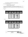
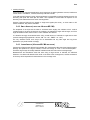
α
α
USER MANUAL
VERSION :1.01
DATE : 06/10/10
USER MANUAL
P1
P2
CONTENT
INTRODUCTION
4
PLEASE READ CAREFULLY BEFORE PROCEEDING
5
1.
8
ALPHA SERIES DESCRIPTION
1.1.
LOUDSPEAKERS
8
1.2.
NEXO TDCONTROLLERS
8
1.3.
THE X-BOW FLYING SYSTEM
8
2.
GENERAL SETUP INSTRUCTIONS
2.1.
9
SPEAKER WIRING
9
2.1.1.
Connectors
9
2.1.2.
Cables
2.2.
10
FLYING THE SYSTEM
11
2.2.1.
Flown Systems Safety
11
2.2.2.
Ground Stacks Safety
12
TDCONTROLLERS SETTINGS
13
2.3.
2.3.1.
SubTDcontroller + S2 parameter board
13
2.3.2.
AlphaTDcontroller
13
2.3.3.
AlphaETDcontroller (for use with Alpha E Series)
14
2.3.4.
NX241 Digital TDcontroller
14
INITIAL SET-UP PRECAUTIONS
15
2.4.
3.
ALPHA ARRAYS - SOME BASIC RULES
15
3.1.
ALPHA S2 PLACEMENT
15
3.2.
SPL VERSUS FREQUENCY
15
3.3.
SPL VERSUS DISTANCE
16
3.3.1.
Single Cabinet
16
3.3.2.
Straight Vertical Array (long throw)
17
3.3.3.
Plane Rectangular Array
17
3.3.4.
Hygrometry and Temperature - Air Absorption
18
α
USER MANUAL
VERSION :1.01
DATE : 06/10/10
P3
3.4.
DIRECTIVITY - COVERAGE
19
3.4.1.
Directivity of Multiple Sources - What Happens ?
19
3.4.2.
Small Arrays (less than 4 Alphas M3 / M8)
20
3.4.3.
Large Arrays (4 Alphas M3 / M8 and above)
20
4.
AMPLIFIERS
21
4.1.
RECOMMENDED POWER
21
4.2.
CURRENT CAPABILITY
21
4.3.
VOLTAGE GAIN
21
II.
TECHNICAL SPECIFICATIONS
22
4.4.
ALPHA S2
22
4.5.
ALPHA B1-15 / B1-18
23
4.6.
ALPHA M3 / M8
24
4.7.
ALPHA EM / EF
25
4.8.
DIRECTIVITY TABLES
26
5.
CURVES
27
5.1.
ALPHA S2
27
5.2.
ALPHA B1-18
27
5.3.
ALPHA B1-15
27
5.4.
ALPHA M3
28
5.5.
ALPHA M8
31
5.6.
ALPHA EM
34
5.7.
ALPHA EF
34
III.
DIMENSIONS
37
IV.
TRANSPORT
38
V.
CONNECTION DIAGRAMS
39
I.
α
USER MANUAL
VERSION :1.01
DATE : 06/10/10
P4
Introduction
Thank you for selecting NEXO Alpha Series. This manual is intended to provide you with
necessary and useful information about your Alpha System:
•
S2
•
B1-15, B1-18
•
M3, M8
•
EM, EF
Please devote some attention to reading this manual. A better understanding of some specific
features of the Alpha Series will help you to operate your system to its full potential.
This manual is intended to be comprehensive, and we hope that it will satisfy your requirements.
Should you require further information, please contact your NEXO agent.
α
USER MANUAL
VERSION :1.01
DATE : 06/10/10
P5
PLEASE READ CAREFULLY BEFORE PROCEEDING
BASIC PRECAUTIONS
Do not open the speaker system or attempt to disassemble the internal parts or modify them in
any way. The speaker system contains no user-serviceable parts. If it should appear to be
malfunctioning or damaged, discontinue use immediately and have it inspected by qualified
NEXO service personnel.
Water exposure: Do not expose the speaker system to direct rain, do not use it near water or in
wet conditions. Do not place containers with liquid on speaker system as they might spill into
openings. If any liquid such as water seeps into the speaker system, have it inspected by
qualified NEXO personnel.
SYSTEM DEPLOYMENT SAFETY RULES
Read User Manual before deployment. Before use of enclosed speaker system,
please ensure that anyone involved in system deployment understands the rigging –
stacking – pole mounting safety rules as described in the speaker system User
Manual. Failure to do this exposes people to potential injury or death.
Always consult qualified NEXO personnel if the device installation requires
construction work and make sure to observe the following precautions:
Mounting precautions
- choose mounting hardware and an installation location that can support the weight of the
speaker system;
-
do not use speaker system handles for suspended installation;
-
do not expose speaker system to excessive dust or vibration, or extreme cold or heat to
prevent possibility of component damage;
-
do not place the speaker system in an unstable position from which it might fall accidentally;
-
if speaker systems uses a stand, ensure that stand specifications are adapted, and that stand
height does not exceed 1.40m/55”; never move the stand while the speaker is in position.
Connection and powering precautions
- remove all connected cables before moving the speaker system;
-
turn off AC power of all power amplifier units before connecting the speaker system;
-
when turning on the AC power to the audio system, always turn on the power amplifier last;
when turning the AC power off, always turn off the power amplifier first;
-
when used in cold conditions, a gradual power ramp up should applied to the system on an 5
mn period to allow the loudspeaker components to stabilize during the very first minutes of
usage.
Inspect the speaker system periodically.
α
USER MANUAL
VERSION :1.01
DATE : 06/10/10
P6
SAFETY INSTRUCTIONS FOR NEXO TD CONTROLLERS
NEXO
ANALOGUE
PSTDCONTROLLERS,
NX242
DIGITAL
CONTROLLER,
NXAMP4x1
AND
NXAMP4x4
POWERED
CONTROLLERS ARE CLASS 1 APPARATUS AND MUST BE EARTHED.
THE GREEN AND YELLOW WIRE OF THE MAINS CORD MUST ALWAYS BE CONNECTED
TO AN INSTALLATION SAFETY EARTH OR GROUND. THE EARTH IS ESSENTIAL FOR
PERSONAL SAFETY AS WELL AS THE CORRECT OPERATION OF THE SYSTEM, AND IS
INTERNALLY CONNECTED TO ALL EXPOSED METAL SURFACES.
- Read these instructions.
-
Keep these instructions.
-
Heed all warnings.
-
Follow all instructions.
-
Do not use this apparatus near water.
-
Clean only with dry cloth.
-
Do not block any ventilation openings. Install in accordance with the manufacturer’s
instructions.
-
Do not install near any heat sources such as radiators, heat registers, stoves, or other
apparatus (including amplifiers) that produce heat.
-
Do not defeat the safety purpose of the polarized or grounding-type plug. A polarized plug has
two blades with one wider than the other. A grounding type plug has two blades and a third
grounding prong. The wide blade or the third prong are provided for your safety. If the provided
plug does not fit into your outlet, consult an electrician for replacement of the obsolete outlet.
(US market)
-
Protect the power cord from being walked on or pinched particularly at plugs, convenience
receptacles, and the point where they exit from the apparatus.
-
Only use attachments/accessories specified by the manufacturer.
-
Unplug this apparatus during lightning storms or when unused for long periods of time.
-
Refer all servicing to qualified service personnel. Servicing is required when the apparatus has
been damaged in any way, such as power-supply cord or plug is damaged, liquid has been
spilled or objects have fallen into the apparatus, the apparatus has been exposed to rain or
moisture, does not operate normally, or has been dropped.
CAUTION
RISK OF ELECTRIC SHOCK
DO NOT OPEN
The lightning flash with arrowhead
symbol, within an equilateral triangle
is intended to alert the user to the
presence of uninsulated “dangerous
voltage” within the product's
enclosure that may be of sufficient
magnitude to constitute a risk of
electric shock to persons.
α
WARNING: To reduce the risk of fire or electric shock,
do not expose this apparatus to rain or moisture.
To avoid electrical shock, do not remove covers.
Dangerous voltages exist inside.
Refer all servicing to qualified personnel only.
USER MANUAL
VERSION :1.01
DATE : 06/10/10
The exclamation point within an
equilateral triangle is intended to
alert the user to the presence of
important operating and
maintenance (servicing) instructions
in the literature accompanying
the appliance.
P7
HIGH SOUND PRESSURE LEVELS
Exposure to extremely high noise levels may cause permanent hearing
loss. Individuals vary considerably in susceptibility to noise-induced hearing
loss but nearly everyone will lose some hearing if exposed to sufficiently
intense noise for a sufficient period of time. The U.S. Government’s
Occupational and Health Administration (OSHA) has specified the following
permissible noise level exposures: Sound Duration Per
Day In Hours
Sound Level dBA, Slow Response
8
90
6
92
4
65
3
97
2
100
1½
102
1
105
½
110
¼ or less
115
According to OSHA, any exposure in excess of the above permissible limits could result in some
hearing loss. Ear plugs or protectors to the ear canals or over the ears must be worn when
operating this amplification system in order to prevent permanent hearing loss, if exposure is in
excess of the limits as set forth above. To ensure against potentially dangerous exposure to high
sound pressure levels, it is recommended that all persons exposed to equipment capable of
producing high sound pressure levels such as this amplification system be protected by hearing
protectors while this unit is in operation.
DISPOSAL OF OLD ELECTRICAL & ELECTRONIC EQUIPMENT
This symbol on the product or on its packaging indicates that it shall not
be treated as household waste. Instead it shall be handed over to the
applicable collection point for the recycling of electrical and electronic
equipment. By ensuring this product is disposed of correctly, you will help
prevent potential negative consequence for the environment and human
health, which could otherwise be caused by inappropriate waste handling
of this product. The recycling of materials will help to conserve natural
resources. For more detailed information about recycling of this product,
please contact your local city office, your household waste disposal
service or the shop where you purchased the product.
α
USER MANUAL
VERSION :1.01
DATE : 06/10/10
P8
1. Alpha Series description
1.1.
LOUDSPEAKERS
The Alpha range includes the following speakers :
• The S2 Sub-bass is a double 18-inch resonator loaded sub-bass, dedicated to very low frequency
reproduction ( < 80 Hz ) ;
• The B1-15 & B1-18 are complex loaded (bass-reflex & exponential horn) bass cabinets ; the B1-15
houses one 15-inch driver, while the B1-18 houses one 18-inch driver ; frequency response ranges from
40 Hz up to 200 Hz ;
• The Mid-high M3 & M8 are concentric horn cabinets dedicated to the 200 Hz - 20 kHz frequency range
reproduction ; the MF range is handled by two exponential horn loaded 10-inch drivers whose response
is optimised by two Nexo designed phase plugs ; the HF range is handled by one constant directivity
horn loaded two-inch Neodynium driver.; M3 coverage is 35° (H) x 35°(V), M8 75° (H) x45° (V) ;
• The Mid-high EM forms part of the recently introduced Alpha E Series; its size and power-rating is
smaller than that of the Alpha M3 & M8 ; the mid range is handled by an exponential horn loaded 10’’
driver, while the HF range is handled by a constant directivity horn loaded ceramic 2’’ driver. Alpha EM
coverage is 75°x30°.
• The compact EF is dedicated to the full audio range reproduction 40 Hz – 20 kHz ; it resembles one EM
and one B1-18 stacked in a monoblock compact format.
Alpha cabinet formats are designed for optimal array assembly (see section VII “Dimensions”) ; all the
cabinets have the same width and depth, height is in multiples of 200 mm.
• Double height (1200 mm ) : Alpha S2, Alpha EF ;
• 4/3 height (800 mm ) : Alpha B1-18 ;
• Single height (600 mm) : Alpha B1-15, Alpha M3, Alpha M8 ;
• 2/3 height (400 mm) : Alpha EM
1.2.
NEXO TDCONTROLLERS
The Alpha Series speakers are associated with the following Nexo TDcontrollers :
•
SubTDcontroller : Alpha S2 ;
•
AlphaTDcontroller : Alpha B1-15, B1-18, M3 & M8 ;
•
AlphaETDcontroller : Alpha B1-18, EM & EF ;
•
NX241 Digital TDcontroller : all current Nexo speakers.
1.3.
THE X-BOW FLYING SYSTEM
The design of the X-BOW flying system has been optimised for the dispersion specifications of
the Alpha range, its mechanical characteristics match accurately the acoustical properties of the
speakers.
The concept of this flying system enables efficient array assembly, with minimum space between
cabinet, thus reducing edge diffraction.
α
USER MANUAL
VERSION :1.01
DATE : 06/10/10
P9
The X-BOW flying system includes four main components, references are:
•
ALXBOW : main chassis (1) ;
•
ALXKIT : hinge (1) and cable links (2) ;
•
ALXBRIDLE : D-ring (1) and leg chains (3);
•
ALXCASE : flight-case for a complete X-BOW flying kit (capacity :4 X-Bows).
2. General Setup Instructions
2.1.
SPEAKER WIRING
2.1.1. CONNECTORS
The loudspeakers are connected via SPEAKON connectors, NL4FC and NL8FC (not supplied). A
wiring diagram is printed on the connection panel located on the back of each cabinet.
The pins of the SPEAKON plugs are identified in/out and paralleled within the enclosures. Each
of these connectors can thus be used independently and simultaneously receive the power
amplifier signal feeding the main and the sub-bass systems : a single 8 conductors cable can
connect the amplifier rack and the speaker.
NB : Alpha S2 back panel features only one 4-pins SPEAKON connector, in order to prevent
paralleling : very few amplifiers could drive such low impedance loads.
B1/15
B1/18
S2
EM
EF
M3
M8
CONNECTOR
SP4
#1
SP4
#2
α
S2
B1-15 / B1-18
M3 / M8
EM / EF
1
±
In / Out VLF
To VLF (S2)
To VLF (S2)
To VLF (S2)
2
±
Not connected
In / Out LF (B1)
To LF (B1)
To LF (B1)
1
±
-
To VLF (S2)
-
-
2
±
-
In / Out LF (B1)
USER MANUAL
VERSION :1.01
DATE : 06/10/10
-
P 10
SP8
#1
SP8
#2
1
±
-
-
In VLF (S2)
In / Out VLF (S2)
2
±
-
-
In / Out LF (B1)
In / Out LF (B1)
3
±
-
-
In / Out MF
4
±
-
1
±
-
-
In VLF (S2)
In VLF (S2)
2
±
-
-
In / Out LF (B1)
In / Out LF (B1)
3
±
-
-
In / Out MF
4
±
-
P : In / Out MF+HF
A : In / Out MF
P : Not connected
-
In / Out HF
A : In / Out HF
P : In / Out MF+HF
A : In / Out MF
P : Not connected
-
In / Out HF
A : In / Out HF
P = MF-HF passive / A = MF-HF active
2.1.2. CABLES
Nexo recommends the exclusive use of multi-conductor cables to connect the system : the cable
kit is compatible with all the cabinets, and there is no possible confusion between VLF, LF, MF
and HF sections.
Cable choice consists mainly of selecting the correct cable section (size) in relation to the load
resistance and the cable length. Too small a cable section will increase its serial resistance, this
would induce power-loss and response variations (damping factor).
For a serial resistance less or equal to 4% of the load impedance (damping factor = 25), the maximum
cable length is given by :
Lmax = Z x S S in mm2, Z in Ohm, Lmax in meters
The table below indicates these values, for 3 common sizes.
Load Impedance (Ω)
2
3
Cable section
4
6
8
12
16
Maximum Length (meters)
1,5 mm² (AWG #14)
3
4.5
6
9
12
18
24
2,5 mm² (AWG #12)
5
7.5
10
15
20
30
40
4 mm² (AWG #10)
8
12
16
24
32
48
64
Important :
• long speaker cables induce capacitive effect that damage the quality of the audio signal (up to hundreds
of pF depending on the quality of the cable, with a low-pass effect in high frequencies) ;
• if long speaker cables are to be used, insure that they do not remain coiled while in use. .
α
USER MANUAL
VERSION :1.01
DATE : 06/10/10
P 11
2.2.
FLYING THE SYSTEM
Alpha Series loudspeakers are equipped with steel anchor plates that can be fitted with the corresponding
Fly Rails. The X-Bow flying system is supplied as an accessory. The X-Bow Flying Manual must be read
before flying the system.
The following points are designed to remind the user of safe practice when flying the X-Bow system. They
cannot address every possible circumstance in which the system might be deployed, therefore the user
must always apply his or her knowledge and experience. If in doubt, seek advice from your NEXO agent.
2.2.1. FLOWN SYSTEMS SAFETY
• Always inspect all the X-Bow components and cabinet Fly Rails for damage before assembly. Pay
special attention to the lifting points, trombone sockets and safety clips. If you suspect that any of the
components are defective, DO NOT USE THE AFFECTED PARTS. Contact your supplier for
replacements.
• Read the X-Bow Flying manual carefully. Also, be familiar with the manuals and safe working
procedures for any ancillary equipment which will be used with the X-Bow.
• Ensure that all local and National regulations regarding the safety and operation of flying equipment are
understood and adhered to. Information on these regulations can usually be obtained from Local
Government Offices.
• When deploying the X-Bow system always wear protective head wear, footwear and eye protection.
• Do not allow inexperienced persons to handle X-Bow flying systems. Installation personnel should be
trained in loudspeaker flying techniques and should be fully conversant with this manual.
• Ensure that motor hoists, hoist control systems and ancillary rigging components are currently certified
as safe and that they pass a visual inspection prior to use.
• Ensure that public and personnel are not allowed to pass beneath the system during the installation
process. The work area should be isolated from public access.
• Never leave the system unattended during the installation process.
• Do not place any object, no matter how small or light, on top of the system during the installation
procedure. The object may fall when the system is flown and is likely to cause injury.
• Secondary safety steels must be installed once the system has been flown to the operating height.
Secondary steels must be fitted irrespective of the local safety standards applicable to the territory.
• Do not fly the system over areas to which the audience has access.
• Ensure that the system is secure and prevented from pivoting about the motor hoist. Avoid any form of
dynamic loading to the assembly.
• NEVER attach any item to the X-Bow other than the NEXO X-BOW accessories.
• When flying outdoor systems ensure that the system is not exposed to wind or snow loads and is
protected from rainfall.
• The X-BOW requires regular inspection and testing by a competent test centre. NEXO recommend that
the system is load tested and certified annually or more frequently if local regulations require.
• When de-rigging the system ensure that the same duty of care is given to the procedure as for the
installation. Pack X-BOW components carefully to prevent damage in transit.
α
USER MANUAL
VERSION :1.01
DATE : 06/10/10
P 12
• Correct training is fundamental to safe practise when working with loudspeakers flying systems. NEXO
recommend that users contact local industry associations for information on specialist course.
Information for UK and International training agencies can be obtained by contacting :
The Production Services Association (PSA),
School Passage,
Kingston-upon-Thames,
KT1 SDU Surrey,
ENGLAND
tel : +44 (0) 181 392 0180
2.2.2. GROUND STACKS SAFETY
Statistically, many more injuries occur due to unstable ground stacked PA systems than those associated
with flown systems. There are several reasons for this fact, however the message is clear :
•
Always survey the supporting structure upon which a ground stack is to be built. Always look beneath
PA wings to inspect the deck support and if necessary ask for the stage scrims and dressings be
removed to allow access.
•
X-BOW components can be used to stabilise ground stacks and to ensure that cabinets remain
securely registered to each other.
•
If the stage surface slopes, as it does in some theatres, ensure that the system is prevented from
sliding forwards due to vibration. This may require the fitting of timber battens to the stage floor.
•
For outdoor systems ensure that that the system is protected from wind forces which might cause the
ground stack to become unstable. Wind forces can be huge, especially upon large systems, and
should never be underestimated. Observe meteorological forecasts, calculate the likely effect upon the
system prior to erection and ensure that the system is secured appropriately.
•
Take care when stacking cabinets. Always employ safe lifting procedures and never attempt to build
stacks without sufficient personnel and equipment.
•
Never allow anyone, whether operators, artists or members of the public to climb onto a ground
stacked PA system. Anyone who must climb over 2m high should be fitted with suitable safely
equipment including a clip-on harness. Please refer to local Health and Safety legislation in your
territory. Your dealer can help with advice on access to this information.
•
Apply the same attention to all safety matters when de-stacking systems.
•
Be aware that safety procedures are as important in the truck and in the warehouse as they are at the
venue.
α
USER MANUAL
VERSION :1.01
DATE : 06/10/10
P 13
2.3.
TDCONTROLLERS SETTINGS
The Alpha Series speakers do not work properly without their associated TDcontrollers.
Sound quality, reliability are totally dependent on the proper use of the TDcontrollers, in
agreement with Nexo instructions.
•
SubTDcontroller : Alpha S2 ;
•
AlphaTDcontroller : Alpha B1-15, B1-18, M3 & M8 ;
•
AlphaETDcontroller : B1-18, EM & EF ;
•
NX241 Digital TDcontroller : all current Nexo speakers.
These device manuals must be read before set-up.
2.3.1. SUBTDCONTROLLER + S2 PARAMETER BOARD
The SubTDcontroller output is a monophonic low-pass filtered sum of Left and Right inputs ;
Therefore, stereophonic use of Alpha S2 requires 2 SubTDcontrollers.
Connecting one single input of the device will reduce signal output by 6 dB. Three different
solutions can be applied to compensate for this 6 dB loss :
•
Increase the output level on the front panel potentiometer by 6 dB ;
•
move the J4 jumper on the mother board to the “A” position (refer to SubTDcontroller manual) ;
•
parallel the inputs with a “Y” split signal cable.
NB : the S2 parameter board disables the main system left an right XLR outputs, as well as the
Burst generator
Front panel phase switch and “Sub Delay” / “Sub Fine Delay” potentiometers are usefull to align
properly Alpha S2 phase relatively to Alpha B1. Below is what must be done depending on the
vertical alignement of the speakers :
S2 & B1 in the same vertical plane : phase Switch in “INV” position, « Sub Delay » potentiometer
at “0” position, , « Sub Fine Delay » rotated 3 steps to the right from the “0” position ;
S2 forward : phase Switch in “INV” position, « Sub Delay » and « Sub Fine Delay »
potentiometers adjusted to the average offset distance
S2 backward : : phase Switch in “INV” position, « Sub Delay » and « Sub Fine Delay »
potentiometers at “0” position.
2.3.2. ALPHATDCONTROLLER
The AlphaTDcontrollers features the following adjustments :
•
LF, MF & HF ouput level ( +/- 6 dB ) ;
•
« Array EQ » potentiometer (see section III.2) ;
•
« X-Over / Wideband » switch.
If the main system is to be used without Alpha S2 sub-bass cabinet, the AlphaTDcontroller must
be used in the “Wideband” mode : the B1-15 response is then extended down to 42 Hz (B1-18
α
USER MANUAL
VERSION :1.01
DATE : 06/10/10
P 14
down to 40Hz).
On the contrary, if the system includes Alpha S2 sub-bass cabinets, and the required SPL level in
the LF region is important, it is then recommended to switch to the “X-Over” mode.
It is also possible to overlap the S2 and B1 responses by switching the AlphaTDcontroller to
“Wideband” mode : the radiated energy will increase in the 40 Hz – 80 Hz range, but the Alpha
B1 power capability will decrease.
2.3.3. ALPHAETDCONTROLLER (FOR USE WITH ALPHA E SERIES)
The AlphaETDcontroller LF output is a low-pass filtered monophonic sum of the stereo inputs ;
MF/HF outputs are stereophonic.
The only available front panel adjustment is the LF output level, on a 12 dB range :
•
LF mono , 1 AlphaETDcontroller, 2 inputs connected : the recommended position is “2” ;
•
LF stereo, 2 AlphaETDcontrollers with 1 input connected : the recommended position is “1”.
The cross-over frequency between Alpha B1-18 and EM being located around 200 Hz, a
monophonic use of the LF range induces random phase relation between cabinets (image
distorsion, inaccurate low-mid frequency reproduction) ; therefore, except for some specific
situation (stadium PA systems, annoucements…), Nexo do not recommend monophonic use of
the LF range.
2.3.4. NX241 DIGITAL TDCONTROLLER
The digital NEXO NX241 controller is able to drive the entire current Nexo range (PS & Alpha
series). Different software setups are loaded for the Alpha Series :
•
Alpha B1-18 / EM / EF : NEXO NX241 is stereo in configuration (2 inputs, 4 outputs).
•
Alpha S2 / B1-15 / M3 & M8, Full Range Mode : NEXO NX241 is in mono configuration (1
input, 4 outputs)
•
Alpha S2 / B1-15 / M3 & M8, Aux Sub Mode : NEXO NX241 is in mono configuration, “Aux
Sub” input drives output “1”, “Full Range” input drives outputs 2, 3 and 4 ;
•
Other setups are loaded, please refer to the NEXO NX241 user manual in order to avoid
inappropriate configurations that could damage your speakers.
Very important :
Due to the DSP processing time, there is no compability between analog SubTD / AlphaTD /
AlphaETD controllers and Digital NX241 unless the signal feeding the analog devices is delayed
by 1.4 ms.
α
USER MANUAL
VERSION :1.01
DATE : 06/10/10
P 15
2.4.
INITIAL SET-UP PRECAUTIONS
When starting up a system including brand new cabinets, NEXO recommends gradual power ramp up. The
loudspeaker components may need stabilising during his very first hours of usage. This is particularly true
for adhesives within the speaker’s moving assemblies.
In all cases, it is advisable to connect the loudspeakers only after all the other components have been
wired and are operating correctly. This is particularly important for the amplifiers and the TDcontroller. It is
a good practice to turn down all the amplifier gains before connecting the cabinets and then turn them up
again individually with a medium level music source fed into the system. The sense LEDs of the
corresponding TDcontroller channel should light up accordingly. This will help to locate cabling errors,
particularly channel line inversions which would disable the TDcontroller protections and may invalidate the
warranty.
3. Alpha Arrays - Some Basic Rules
The concept of arraying speakers derives from two requirements :
• increased sound pressure level ;
• extended coverage area.
Array behaviour is very complex, and a bad design can lead to very poor results. The Alpha system was
designed to be flexible, allowing the user to optimise his design for a dedicated situation ; its development
included a long measurement program on a very large variety of arrays. Below are some simple rules that
the user must respect in his design.
3.1.
ALPHA S2 PLACEMENT
The nominal efficiency data for Alpha S2 is given for when positioned on the floor (half-space). When flown,
the sensitivity is 3 dB lower ; on the contrary, if the Alpha S2 is positioned in an angle - respectively in a
corner -, the sensitivity will increase by 3 dB - respectively by 6 dB.
3.2.
SPL VERSUS FREQUENCY
Array frequency response is strongly related to wavelength and array architecture.
• At low frequencies, wavelength being very large in relation to the size of the cabinets, speakers set
close to each other will always radiate in phase. The gain in sound pressure level LGSPL will be of 6 dB
per doubling, i.e. if n Alpha S2 or B1 are installed :
LGSPL(20Hz-100Hz) = 20 log10(n)
• In the mid frequency range, the gain depends on the configuration of the array, and will range from 3 to
6 dB per doubling, i.e. for n Alpha M3, M8, EM or EF :
10 log10(n) ≤ LGSPL(100Hz-1kHz) ≤ 20 log10(n)
α
USER MANUAL
VERSION :1.01
DATE : 06/10/10
P 16
• At high frequencies, wavelength being short in relation to the size of the cabinet, the gain level is
smaller : no gain will be obtained for cabinets angled at their nominal coverage, maximum gain will be
obtained for n cabinets pointing in the same direction. Therefore, the gain will range from 0 to 3 dB per
doubling ; for n Alpha M3, M8, EM or EF :
0 ≤ LGSPL(1kHz-10kHz) ≤ 10 log10(n)
• The Alpha TDcontroller Array EQ is derived from array measurements to compensate the array coupling
effect.
AlphaTD Controller Array EQ / Frequency (Hz) / Gain (dB)
10.000
8.0000
6.0000
4.0000
2.0000
0.0
-2.000
-4.000
-6.000
-8.000
-10.00
20
100
1k
10k
20k
Alpha TDcontroller Array EQ
3.3.
SPL VERSUS DISTANCE
In open-air conditions, the level of sound at a given distance is related to the following parameters :
• the size and the geometry of the source, which determines the shape of the sound wave (spherical,
cylindrical, plane) ;
• hygrometry and temperature : viscosity of the air and thermal conduction cause an energy loss
increasing with frequency. This phenomena is referred to as excess attenuation.
3.3.1. SINGLE CABINET
Lp(1m) being the sound pressure level at 1m, the level at a distance d (in meters) is given by :
Lp(d) = Lp(1m) - 20 log10(d)
Sound Pressure Level (dBSPL) / distance (meters)
110.00
100.00
90.000
80.000
70.000
60.000
1
10
Single Cabinet SPL versus Distance
α
USER MANUAL
VERSION :1.01
DATE : 06/10/10
100
P 17
For example, if the level measured at 1 meter is Lp(1m) = 100 dBSPL, the level at 2 meters will be 94
dBSPL, 80 dBSPL at 10 meters and so on. Note that under these conditions of small source and open air,
the sound pressure level will be decreasing by 6 dB when doubling the distance.
3.3.2. STRAIGHT VERTICAL ARRAY (LONG THROW)
Some open-air applications might require loud level on a wide frequency range at a long distance. It is then
recommended to stack a large number of Alpha M3/M8/EM vertically. Up to a determined distance function of the frequency and the height of the stack -, the sound wave is cylindrical (3dB/2d) ; it becomes
progressively spherical (6dB/2d) above that distance.
Sound Pressure Level (dBSPL) / distance (meters)
110.00
100.00
90.000
80.000
70.000
60.000
1
10
100
Transition from cylindrical to spherical wavefront
3.3.3. PLANE RECTANGULAR ARRAY
When both dimensions of an array are greater than the listening distance, the energy is spread over a
plane surface : there is no attenuation with distance. As the listening distance increases, the sound wave
becomes cylindrical (-3dB/2d), and then spherical (-6dB/2d)
Sound Pressure Level (dBSPL) / distance (meters)
110.00
100.00
90.000
80.000
70.000
60.000
1
Transition from plane to cylindrical, to spherical wavefront
α
USER MANUAL
VERSION :1.01
DATE : 06/10/10
10
100
P 18
3.3.4. HYGROMETRY AND TEMPERATURE - AIR ABSORPTION
Under usual conditions, air absorption :
−
increases when relative humidity decreases ;
−
increases when temperature decreases.
Air absorption gives a linear attenuation, i.e. a constant value of loss of dB per meter : if 1 dB is lost from
10 to 20 meters, 2 dB will be lost from 20 to 40 meters, 4 dB from 40 to 80 meters and so on...
The tables below list these values for normalised frequencies, and various values of relative humidity and
temperature :
At 20°C :
[dB] loss / meter
Up to 1 kHz
2 kHz
4 kHz
8 kHz
16 kHz
RH 20%
0
0.02
0.06
0.20
0.66
RH 50%
0
0.01
0.03
0.08
0.27
RH 80%
0
0.00
0.02
0.05
0.17
Frequency (Hz) / Attenuation (dB)
10.000
0.0
-10.00
-20.00
-30.00
-40.00
20
100
1k
10k
20k
Air absorption over a 50m distance ; RH=20%-50%-80%
At RH 50% :
[dB] loss / meter
Up to 1 kHz
2 kHz
4 kHz
8 kHz
16 kHz
10°C
0
0.01
0.04
0.13
0.43
20°C
0
0.01
0.03
0.08
0.27
30°C
0
0.01
0.02
0.06
0.19
AUDIO PRECISION
10.000
LEVEL(dBV)
vs
FREQ(Hz)
17 JUL 97 19:30:05
0.0
-10.00
-20.00
-30.00
-40.00
20
100
1k
10k
20k
Air absorption over a 50m distance ; t=10°C-20°C-30°C
α
USER MANUAL
VERSION :1.01
DATE : 06/10/10
P 19
The speed of sound C varies with temperature according to the formula below :
C = 20 t° + 273
where t° is the temperature in °C
The delay time between two sources spaced at a distance d is then :
∆t = C/d
3.4.
DIRECTIVITY - COVERAGE
The two main qualities one might expect from a cabinet for array constructions are :
• a good directivity control in the mid an high frequency region, which guarantees the steadiness of the
interference region where dips and lobes occur ;
• a strong roll-off of the directivity function at the -6dB cut-off angle, which minimises the size of the
interference region.
The Alpha series cabinets were designed to respect these two criteria. Particularly, the Alpha M3
features a constant coverage angle +/- 5° from as low as 800 Hz up to 12 kHz, with high values of dB
loss / degrees at cut-off angle.
3.4.1. DIRECTIVITY OF MULTIPLE SOURCES - WHAT HAPPENS ?
In order to understand the coverage behaviour of combined sources, wavelength must be related to the
space between sources.
The wavelength λ (in meters) of o sine wave is determined by :
λ = C/f
where f is the frequency of the sine wave
This gives : λ(20Hz) = 17 m, λ(100Hz) = 3.4 m, λ(1kHz) = 34 cm and λ(20kHz) = 1.7 cm
• interference
The distance between sources generates a pathlength difference between the two signals that is nil on
axis and increases with the listening angle. If this pathlength difference increases to half the wavelength
in a specific direction, the two signals will cancel in that direction. This phenomenon is often described
as « interference ».
Pathlength
difference
pathlength difference between two sound waves
α
USER MANUAL
VERSION :1.01
DATE : 06/10/10
P 20
• resulting directivity
At low frequencies, because wavelength is much larger than the spacing between sources, interference
cannot result in cancellation ; however, directivity index will increase.
In the mid and high frequency range, where wavelength is comparable to spacing between sources, the
directivity polar plots will show dips and lobes. The amplitude of these lobes will depend on the
directivity of the individual sources and on their angulation.
However, lobes and dips will only appear on single tone signals (sine wave) ; on third octave or full
octave excitement, they will be smoothed.
3.4.2. SMALL ARRAYS (LESS THAN 4 ALPHAS M3 / M8)
The amplitude of the dips and the lobes is minimised when angling the cabinets at their nominal
coverage angle. If the angle is less than the coverage, the interference region will be larger, and if the
angle exceeds that value, there will be a « hole » between the cabinets.
It is therefore strongly recommended when using a small amount of cabinets to angle them at their
nominal coverage angle (Alpha M3 : 35°x35°, M8 : 75° x 45° ; EM/EF : 75° x 30°).
The only situations where such arrays can be assembled with very little angle are long throw
applications (very small vertical coverage).
3.4.3. LARGE ARRAYS (4 ALPHAS M3 / M8 AND ABOVE)
Construction of large arrays derives from important SPL requirements rather than large listening angles:
although the Alpha M3 is a high Q cabinet, 4 boxes are enough to cover a 140° horizontal plane...
Therefore, large arrays will usually assemble cabinets at less than their nominal coverage angle.
Measurements and simulations show that when using a large amount of cabinets, the individual
behaviour of a cabinet will determine the roll-off on the limits of the coverage zone, and the architecture
of the array will be responsible for the behaviour in the coverage zone.
α
USER MANUAL
VERSION :1.01
DATE : 06/10/10
P 21
4. Amplifiers
4.1.
RECOMMENDED POWER
For best results, NEXO specifies a range of amplifier powers relative to the capacity of the cabinets (see
« Technical Specifications »). The use of amplifiers with lower power rating has no justification other than
budgetary. On the contrary, high power amplifiers (within reasonable limit) present no real technical
problem (bearing in mind that the servo-control system limits the delivered power when needed), but may
simply represent an unnecessary expense.
4.2.
CURRENT CAPABILITY
When evaluating an amplifier, it is important to take account of its behaviour under load conditions (current
capacity) : a speaker system is highly reactive, with transient signals like music it can require a lot more
current than the nominal impedance would indicate. Apart from the manufacturer’ specifications, it is
possible to test the amplifier with two times the intended number of cabinets (two cabinets per channel in
place of one, four in place of two, etc...), and drive the system to the onset of clipping. If there is no
noticeable (audio) signal degradation, the amplifier is well suited (do not take much notice of amplifier
heating after several minutes but amplifier protection should not appear too quickly).
4.3.
VOLTAGE GAIN
If Vin is the voltage applied to the input of the amplifier (small, so that the amplifier does not clip, typically
100 mV@1kHz between pin 2 and pin 3 of the XLR connector), and Vout the voltage measured at the output
of the amplifier (between black and red barrier strip, in Volts), then the voltage gain is :
LG = 20 log10 (Vout / Vin)
It is very important that all the amplifiers within an installation have closely matched gains ; the variation
allowed must be less than +/- 0.5 dB. This precaution is very important for reliability in the case where only
one TD Controller is being used for several amplifiers. It is also recommended to use the same amplifiers
throughout and to check their gain periodically. If some different amplifiers must be mixed (e.g. in rental
situations), at least check their gain and adjust as necessary.
NEXO recommends the use of low gain amplifiers whenever possible, 26 dB being the preferred value as it
is quite common. The use of high-gain amplifiers has a negative effect in terms of signal to noise ratios :
the delivered noise is increased whilst the maximum voltage level remains the same (4.5 V peak at the
input is enough to drive a 26 dB gain, 500 W / 8 Ohm power amplifier to the onset of clipping).
Some amplifiers use non-linear compression circuits to smooth signal before clipping: for correct use of the
TD Controllers, NEXO recommends that these circuits are switched off in order to maintain the amplifier
linearity.
α
USER MANUAL
VERSION :1.01
DATE : 06/10/10
P 22
II.
TECHNICAL SPECIFICATIONS
4.4.
ALPHA S2
SYSTEM SPECS
Frequency Response [a]
ALPHA S2 with SubTD Controller
32(?) Hz – 64 Hz ± 3 dB
Usable Range @-6dB [a]
29 Hz – 180 Hz
Sensitivity 1W @ 1m [b]
105 dB SPL
Peak SPL @ 1m [b]
140 dB Peak
Nominal Impedance
3 ohms (2.7 min)
Recommended Amplifiers
1800 to 2400 Watts into 3 ohms
FEATURES
ALPHA S2
Components
2 x 18’’ (46cm) long excursion 6 ohms drivers, high efficiency acoustic load.
Height x Width x Depth
1200 x 689 x 754 mm carpet version
(47 ¼" x 27 1/8 " x 29 11/16")
Shape
22.5 Trapezoid
Weight : Net
85 kg (187 Lb)
with wheelboard: 95 kg (209 Lb)
Connectors
1 x 4 poles Speakon
Construction
Baltic Birch with Dark Grey carpeting, Structured Black coating painting finish also available.
1+ & 1- (Sub S2)
Handles
4 Metal Bar Handles
Front Finish
Acoustic Foam on hex perforated steel grid (77% transparent)
Flying points
4 Flying Tracks on front (7 positions on 2° steps)
Top to bottom Steel Backplate
2 Flying Tracks on Back (Hinge fixing)
Internal top to bottom Steel links
Painted version without Flying Tracks also available
Fixed Installation
The X-Bow Flying Tracks can also receive standard Aircraft Flying Fittings.
As part of a policy of continual improvement, NEXO reserves the right to change specifications without notice.
[a]
Response Curves and Data : Anechoic Far Field above 200 Hz, Half-space Anechoic below 200 Hz.
Usable Range Data : Frequency Response Capability with TD crossover slopes removed.
[b]
Sensitivity & Peak SPL : will depend on spectral distribution. Measured with band limited Pink Noise.
Refers to the specified +/- 3 dB range. Data are for Speaker + Processor + recommended amplifier combinations.
α
USER MANUAL
VERSION :1.01
DATE : 06/10/10
P 23
4.5.
ALPHA B1-15 / B1-18
SYSTEM SPECS
ALPHA B1-15
ALPHA B1-18
Frequency Response [a]
Wideband : 42 Hz – 180 Hz ± 3 dB
Xover : 80 Hz – 190 Hz ± 3 dB
40 Hz – 230 Hz ± 3 dB
Usable Range @-6dB [a]
39 Hz – 600 Hz
38 Hz – 600 Hz
Sensitivity 1W @ 1m [b]
106 dB SPL
107 dB SPL Nominal
Peak SPL @ 1m [b]
140 dB Peak
142 dB Peak
Nominal Impedance
6 ohms (5.2 mini)
6 ohms (4.7 mini)
Recommended Amplifiers
900 to 1200 Watts into 6 ohms
900 to 1400 Watts into 6 ohms
FEATURES
Components
Height x Width x Depth
ALPHA B1-15
Shape
Weight : Net
Connectors
ALPHA B1-18
1 x 15" (38 cm) 6 ohms
Folded Horn, Composite Curve
600 x 689 x 754 mm
(23 5/8" x 27 1/8 " x 29 11/16")
1 x 18" (46 cm) 6 ohms
Folded Horn, Composite Curve
800 x 689 x 754 mm
(31.49" x 27 1/8 " x 29 11/16")
22.5° Trapezoid
51 kg (112 Lb)
with wheelboard : 58 kg (128 Lb)
2x 4 poles Speakon (In / Out)
69.9 kg (155 Lb)
with wheelboard : 79 kg (175 Lb)
1+ & 1- (Sub S2)
2+ & 2- (Bass B1)
Construction
Baltic Birch with Dark Grey carpeting, Structured Black coating painting finish also available.
Handles
2 Metal Bar Handles
Front Finish
Flying points
Fixed Installation
4 Metal Bar Handles
Acoustic Foam on hex perforated steel grid (77% transparent)
4 Flying Tracks on front (7 positions on 2° steps)
Top to bottom Steel Backplate
4 Flying Tracks on Back (Hinge fixing)
Internal top to bottom Steel links
Painted version without Flying Tracks also
available
Crossbow Flying System cabinet Hardware:
Optional 4 Flying Tracks on Front
Internal top to bottom Steel links
Optional 2 Flying tracks on back (Hinge fixing)
Painted version without Flying Tracks also
available
The X-Bow Flying Tracks can also receive standard Aircraft Flying Fittings.
As part of a policy of continual improvement, NEXO reserves the right to change specifications without notice.
[a]
Response Curves and Data : Anechoic Far Field above 200 Hz, Half-space Anechoic below 200 Hz.
Usable Range Data : Frequency Response Capability with TD crossover slopes removed.
[b]
Sensitivity & Peak SPL : will depend on spectral distribution. Measured with band limited Pink Noise.
Refers to the specified +/- 3 dB range. Data are for Speaker + Processor + recommended amplifier combinations.
α
USER MANUAL
VERSION :1.01
DATE : 06/10/10
P 24
4.6.
ALPHA M3 / M8
SYSTEM SPECS
ALPHA M3
ALPHA M8
Frequency Response [a]
190 Hz – 19 kHz ± 3 dB
190 Hz – 19 kHz ± 3 dB
Usable Range @-6dB [a]
150 Hz – 20 kHz
150 Hz – 20 kHz
Sensitivity 1W @ 1m [b]
110 dB SPL
108 dB SPL
Peak SPL @ 1m [b]
145 dB Peak
143 dB Peak
Dispersion [c]
35° x 35°
75° x 45° (HF Horn Rotatable)
Directivity : Q & DI [c]
Q = 32 – DI = 15 dB (Nominal f > 630 Hz)
Q = 20 – DI = 13 dB (Nominal f > 630 Hz)
Nominal Impedance
MF : 12 ohms (15.5 min)
HF : 12 ohms (8.0 min)
MF : 650 to 900 Watts into 12 ohms
HF : 350 to 500 Watts into 12 ohms
MF : 12 ohms (15.5 min)
HF : 12 ohms (8.0 min)
MF : 650 to 900 Watts into 12 ohms
HF : 350 to 500 Watts into 12 ohms
Recommended Amplifiers
FEATURES
Components
Height x Width x Depth
ALPHA M3
Shape
22.5° Trapezoid
Weight : Net
2 x 8 poles Speakon (In / Out)
Connectors
1 x 4 poles Speakon (to B1 & S2)
Construction
ALPHA M8
MF : 2 x 10" (24 cm) 8 ohms 3” Coil Drivers ; Dual Ring Phase Plugs
HF : 1 x 3’’ Neodynium Driver, Titanium diaphragm
Coaxial mounted waveguide
600 x 689 x 754 mm Carpet version
(23 5/8" x 27 1/8 " x 29 11/16")
57 kg (126 Lb)
with wheelboard: 64 kg (141 Lb)
1+ & 1- (Sub S2)
2+ & 2- (Bass B1)
3+ & 3- (MF)
4+ & 4- (HF)
1+ & 1- (Sub S2)
2+ & 2- (Bass B1)
Baltic Birch with Dark Grey carpeting, Structured Black coating painting finish also available.
Handles
2 Metal Bar Handles
Front Finish
Acoustic Foam on hex perforated steel grid (77% transparent)
Flying points
4 Flying Tracks on front (7 positions on 2° steps)
Top to bottom Steel Backplate
4 Flying Tracks on Back (Hinge fixing)
Internal top to bottom Steel links
Painted version without Flying Tracks also available
Fixed Installation
The X-Bow Flying Tracks can also receive standard Aircraft Flying Fittings.
As part of a policy of continual improvement, NEXO reserves the right to change specifications without notice.
[a]
Response Curves and Data : Anechoic Far Field above 200 Hz, Half-space Anechoic below 200 Hz.
Usable Range Data : Frequency Response Capability with TD crossover slopes removed.
[b]
Sensitivity & Peak SPL : will depend on spectral distribution. Measured with band limited Pink Noise.
Refers to the specified +/- 3 dB range. Data are for Speaker + Processor + recommended amplifier combinations.
[c]
Directivity Curves and Data : 1/3 octave smoothed frequency response, normalised to On-Axis response.
Data obtained by computer processing on off-axis response curves.
α
USER MANUAL
VERSION :1.01
DATE : 06/10/10
P 25
4.7.
ALPHA EM / EF
SYSTEM SPECS
ALPHA EM
ALPHA EF
Frequency Response [a]
220 Hz – 19 kHz ± 3 dB
Usable Range @-6dB [a]
180 Hz – 20 kHz ± 6 dB
38 Hz – 20 kHz ± 6 dB
Sensitivity 1W @ 1m [b]
107 dB SPL
107 dB SPL
140 dB Peak
LF : 142 dB Peak
MF/HF : 140 dB Peak
Peak SPL @ 1m [b]
40 Hz – 19 kHz ± 3 dB
Dispersion [c]
75° x 30°
75° x 30°
Directivity : Q & DI [c]
Q = 25 – DI = 14 dB (Nominal f > 630 Hz)
Q = 25 – DI = 14 dB (Nominal f > 630 Hz)
Cross-Over Frequency
Nominal Impedance
Recommended Amplifiers
FEATURES
Components
Height x Width x Depth
8 ohms (7.5 min)
700 to 1000 Watts into 8 ohms
ALPHA EM
Connectors
Construction
Handles
Front Finish
Flying points (optional)
Fixed Installation
ALPHA EF
MF : 1 x 10" (24 cm) 8 ohms
HF : 1 x 3’’ Ceramic Driver, Titanium diaphragm
Coaxial mounted waveguide
400 x 689 x 754 mm Carpet version
(15 3/4" x 27 1/8 " x 29 11/16")
Shape
Weight : Net
LF/MF : 210 Hz (Active)
MF/HF : 2.2 kHz (Passive)
LF : 6 ohms (4.7 min)
MF/HF : 8 ohms (7.5 min)
MF : 900 to 1400 Watts into 6 ohms
MF/HF : 700 to 1000 Watts into 8 ohms
MF/HF : 2.2 kHz (Passive)
LF : 1 x 18’’ (46cm) 6 Ohms Composite Curve
MF : 1 x 10" (24 cm) 8 ohms
HF : 1 x 3’’ Ceramic Driver, Titanium diaphragm
Coaxial mounted waveguide
1200 x 689 x 754 mm Carpet version
(47 1/4" x 27 1/8 " x 29 11/16")
22.5° Trapezoid
46.6 kg (99 Lb)
98 kg (209 Lb)
with wheelboard : 105 kg (231 Lb)
2 x 8 poles Speakon (In / Out)
1+ & 1- (Sub-bass S2)
2+ & 2- (Bass B1)
3+ & 3- (MF/HF)
4+ & 4- (NC)
1 x 4 poles Speakon (to B1 & S2)
1+ & 1- (Sub-bass S2))
2+ & 2- (Bass B1)
Baltic Birch with Dark Grey carpeting, Structured Black coating painting finish also available.
2 Metal Bar Handles
4 Metal Bar Handles
Acoustic Foam on hex perforated steel grid (77% transparent)
4 Flying Tracks on front (7 positions on 2° steps)
Top to bottom Steel Backplate
4 Flying Tracks on Back (Hinge fixing)
Internal top to bottom Steel links
Painted version without Flying Tracks also available
The X-Bow Flying Tracks can also receive standard Aircraft Flying Fittings.
As part of a policy of continual improvement, NEXO reserves the right to change specifications without notice.
[a]
Response Curves and Data : Anechoic Far Field above 200 Hz, Half-space Anechoic below 200 Hz.
Usable Range Data : Frequency Response Capability with TD crossover slopes removed.
[b]
Sensitivity & Peak SPL : will depend on spectral distribution. Measured with band limited Pink Noise.
Refers to the specified +/- 3 dB range. Data are for Speaker + Processor + recommended amplifier combinations.
[c]
Directivity Curves and Data : 1/3 octave smoothed frequency response, normalised to On-Axis response.
Data obtained by computer processing on off-axis response curves.
α
USER MANUAL
VERSION :1.01
DATE : 06/10/10
P 26
4.8.
DIRECTIVITY TABLES
Off-Axis Attenuation from On-Axis Frequency Response (dB)
125 Hz
Angle / dB
0
10
20
30
40
50
60
70
80
90
100
110
120
130
140
150
160
B1+M3 hor
0.0
0.5
1.3
2.0
2.5
3.5
4.3
4.5
5.0
4.8
6.0
6.0
6.5
6.8
6.3
7.0
6.3
B1+M3 vert
0.0
0.3
0.5
1.5
2.0
2.8
3.5
4.3
4.8
5.5
6.0
6.8
6.8
6.0
7.0
6.5
6.0
B1+M8 hor
0.0
0.5
1.3
2.0
2.5
3.5
4.3
4.5
5.0
4.8
6.0
6.0
6.5
6.8
6.3
7.0
6.3
5.8
5.5
B1+M8 vert
0.0
0.3
0.5
1.5
2.0
2.8
3.5
4.3
4.8
5.5
6.0
6.8
6.8
6.0
7.0
6.5
6.0
5.5
5.5
EM/EF hor
0.0
EM/EF vert
0.0
0.3
0.0
170
5.8
5.5
180
5.5
5.5
0.5
1.0
2.0
2.5
3.3
4.0
4.5
5.0
5.5
6.3
6.0
6.0
5.8
5.3
4.5
4.3
4.0
0.3
0.5
1.0
1.5
2.0
2.8
3.5
4.0
4.8
5.5
6.0
6.0
5.8
5.0
4.5
4.3
4.0
170
7.5
8.0
180
7.5
7.5
7.5
7.8
7.8
7.8
250 Hz
Angle / dB
0
10
20
30
40
50
60
70
80
90
100
110
120
130
140
150
160
B1+M3 hor
0.0
0.3
1.0
2.0
3.0
4.3
5.5
6.8
8.0
8.5
9.5
9.8
9.8
10.0
9.5
8.8
8.0
B1+M3 vert
0.0
0.3
0.8
1.5
2.5
4.0
5.3
6.5
7.5
8.5
9.8
10.8
12.0
12.0
11.0
9.8
8.5
B1+M8 hor
0.0
0.3
0.8
2.0
3.0
4.3
6.0
7.0
8.0
8.8
9.3
10.0
10.5
10.3
10.0
9.3
8.0
B1+M8 vert
0.0
0.3
1.0
1.8
3.0
4.3
5.5
7.0
8.0
9.3
10.3
11.3
12.0
12.0
11.0
9.8
8.8
EM/EF hor
0.0
0.3
0.8
1.8
3.0
4.0
5.3
6.3
7.0
7.8
8.0
8.5
8.8
8.8
8.3
7.5
6.5
6.0
6.0
EM/EF vert
0.0
0.0
0.5
1.0
1.5
2.5
3.3
4.0
4.8
5.5
6.5
7.5
8.5
8.8
8.8
8.0
7.0
6.3
6.0
500 Hz
Angle / dB
0
10
20
30
40
50
60
70
80
90
100
110
120
130
140
150
160
170
180
:B1+M3 hor
0.0
0.5
2.0
4.5
7.3
9.8
12.0
14.0
15.8
16.8
17.8
18.8
19.0
18.8
18.5
18.0
17.0
15.0
14.5
B1+M3 vert
0.0
0.5
2.0
4.3
6.8
9.3
11.8
13.5
15.0
16.3
17.3
18.3
19.0
20.0
20.5
21.0
19.3
16.0
14.5
B1+M8 hor
0.0
0.5
2.0
4.3
6.5
9.0
12.0
14.0
16.3
17.8
18.5
19.0
19.3
19.5
19.5
19.5
17.5
15.5
15.8
B1+M8 vert
0.0
0.5
2.0
4.0
6.5
8.8
11.3
13.5
15.5
16.8
17.5
18.3
19.3
20.5
21.5
21.8
19.5
16.5
15.8
EM/EF hor
0.0
0.5
2.0
4.0
6.5
9.3
11.8
14.0
15.8
17.0
17.0
17.3
17.8
18.0
17.8
16.3
14.3
12.5
12.0
EM/EF vert
0.0
0.3
1.0
1.8
3.0
4.5
6.0
7.5
8.8
10.0
11.0
11.3
12.0
13.0
15.0
16.3
14.5
12.8
12.0
1000 Hz
Angle / dB
0
10
20
30
40
50
60
70
80
90
100
110
120
130
140
150
160
170
180
B1+M3 hor
0.0
1.3
5.0
10.0
13.0
14.5
15.8
17.3
18.8
20.0
21.5
22.3
23.5
24.5
23.5
20.5
21.0
18.5
16.8
B1+M3 vert
0.0
1.8
6.0
10.8
12.3
13.0
14.3
15.5
17.3
18.5
19.5
20.5
21.5
22.0
22.8
23.5
26.3
20.5
16.8
B1+M8 hor
0.0
1.5
5.5
9.8
11.5
12.5
13.8
15.3
17.0
18.8
19.5
21.0
22.0
22.3
22.0
20.0
20.8
17.5
16.3
B1+M8 vert
0.0
1.8
6.5
11.0
11.5
12.0
13.3
15.0
16.5
17.8
18.5
20.0
21.0
21.3
21.8
21.5
20.5
19.5
16.3
EM/EF hor
0.0
2.0
6.3
9.8
9.5
9.5
10.3
11.3
12.5
13.5
14.3
15.3
16.5
17.5
18.8
17.3
18.8
19.0
17.0
EM/EF vert
0.0
0.8
2.5
5.0
8.0
10.8
13.0
15.3
17.5
19.3
20.3
21.0
21.5
22.0
23.0
23.0
21.3
19.0
17.0
2000 Hz
Angle / dB
0
10
20
30
40
50
60
70
80
90
100
110
120
130
140
150
160
170
180
B1+M3 hor
0.0
1.3
6.0
14.0
14.5
16.0
18.3
19.8
21.5
23.3
25.5
27.5
28.5
30.0
30.0
29.8
27.8
27.3
28.0
B1+M3 vert
0.0
1.8
7.0
14.3
15.8
17.0
20.0
21.8
23.3
24.5
25.8
27.0
28.3
29.0
29.0
29.3
29.5
29.3
28.0
B1+M8 hor
0.0
1.5
5.8
10.5
11.5
11.3
13.5
16.5
20.5
24.0
25.5
28.0
27.3
27.5
27.5
28.5
27.0
28.5
28.0
B1+M8 vert
0.0
2.3
7.5
12.5
15.0
16.0
18.0
20.5
22.5
24.5
25.8
27.0
28.0
29.0
27.8
26.8
29.0
29.5
28.0
EM/EF hor
0.0
1.5
4.5
7.8
7.8
8.0
10.0
12.5
15.5
18.0
19.5
20.0
21.5
22.8
23.0
23.8
25.5
25.8
24.0
EM/EF vert
0.0
1.8
5.5
10.5
14.5
16.5
18.3
20.0
22.0
24.0
25.5
26.3
27.0
28.0
29.3
28.0
26.5
25.0
24.0
4000 Hz
Angle / dB
0
10
20
30
40
50
60
70
80
90
100
110
120
130
140
150
160
170
180
M3 hor
0.0
2.0
6.5
11.3
16.0
19.5
22.5
25.5
28.8
31.8
34.5
37.3
38.3
39.8
40.5
40.3
40.5
38.0
37.8
M3 vert
0.0
2.3
6.8
12.3
16.5
19.0
22.5
25.5
29.5
32.0
34.5
36.8
38.3
39.3
39.3
40.0
39.5
38.8
37.8
M8 hor
0.0
1.0
3.8
6.8
11.3
14.3
18.0
21.0
25.0
28.8
31.0
33.0
34.3
35.0
36.0
37.0
38.0
39.5
38.0
M8 vert
0.0
2.0
5.8
11.0
15.5
20.0
23.3
27.0
30.0
33.0
34.8
36.5
37.3
38.0
39.0
40.0
41.0
40.5
38.0
EM/EF hor
0.0
1.5
3.8
5.5
6.8
9.3
12.3
16.0
19.8
23.8
26.5
28.3
29.3
30.0
31.0
33.8
33.0
33.5
32.3
EM/EF vert
0.0
2.8
7.8
12.8
16.3
19.3
21.8
24.0
26.0
28.3
30.0
31.0
32.5
33.8
34.5
35.0
34.8
34.0
32.3
8000 Hz
Angle / dB
0
10
20
30
40
50
60
70
80
90
100
110
120
130
140
150
160
170
180
M3 hor
0.0
1.5
7.0
13.3
18.5
22.3
25.0
29.5
34.8
39.0
42.8
45.3
45.5
47.8
48.8
47.0
48.0
46.3
47.3
M3 vert
0.0
1.8
7.0
13.5
18.8
21.5
25.0
28.5
33.8
38.0
40.5
42.5
44.5
45.5
46.3
47.3
48.0
49.0
47.3
M8 hor
0.0
0.3
2.0
6.3
11.8
15.0
19.0
22.5
28.0
31.8
40.5
43.0
44.0
45.0
46.0
47.0
48.0
49.0
47.5
M8 vert
0.0
1.8
5.8
11.3
16.5
20.8
24.3
29.0
32.0
35.0
42.0
44.0
45.0
46.0
47.0
48.0
49.0
47.0
47.5
EM/EF hor
0.0
0.8
3.0
6.0
8.0
11.5
14.5
18.5
24.3
30.0
33.8
36.3
37.0
39.3
40.5
41.8
41.8
42.5
42.0
EM/EF vert
0.0
3.3
9.5
15.5
20.0
23.3
24.5
26.5
30.8
34.3
36.0
38.0
38.8
39.8
40.0
41.5
41.5
40.8
42.0
NB data available in EASE™ format.
α
USER MANUAL
VERSION :1.01
DATE : 06/10/10
P 27
5. CURVES
5.1.
ALPHA S2
On Axis Response Alpha S2 With SubTD Controller (dB)
Impedance Alpha S2 (Ohm)
10.000
50
0.0
10
-10.00
-20.00
-30.00
30
100
1k
10k
20k
Frequency Response with SubTD Controller (dB)
5.2.
2
10
100
1k
10k
1k
10k
1k
10k
Impedance (Ohms)
ALPHA B1-18
On Axis Response Alpha B1-18 With AlphaETD Controller (dB)
Impedance Alpha B1-18 (Ohm)
10.000
50
0.0
-10.00
10
-20.00
-30.00
30
100
1k
10k
20k
Frequency Response with AlphaETD Controller (dB)
5.3.
2
10
100
Impedance (Ohms)
ALPHA B1-15
On Axis Response Alpha B1-15 With AlphaTD Controller (Overlap/X-over)
Impedance Alpha B1-15 (Ohm)
10.000
50
0.0
10
-10.00
-20.00
-30.00
30
100
1k
10k
20k
Frequency Response with AlphaTD Controller (dB)
Black : Overlap Mode, Grey : X-Over mode
2
10
100
Impedance (Ohms)
Frequency Response Curves : Anechoic Far Field above 200 Hz, Half-space Anechoic below 200 Hz.
Impedance : Voltage to Current Ratio, Free Field measurement
Off-Axis Frequency Response : 1/3 octave smoothed frequency response, normalised to On-Axis response.
Directivity Curve, Coverage Angle and Polar Diagram from computer processing on off-axis response curves.
α
USER MANUAL
VERSION :1.01
DATE : 06/10/10
P 28
5.4.
ALPHA M3
On Axis Response Alpha M3 With AlphaTD Controller (dB)
Impedance Alpha M3 (Ohm)
10.000
50
0.0
10
-10.00
-20.00
-30.00
20
100
1k
10k
2
20
20k
Frequency Response with AlphaTD Controller (dB)
100
1k
10k
20k
Impedance (Ohms)
Black : MF, Grey : HF
Directivity Index (dB) & Q Alpha M3
Coverage Angle Alpha M3 (Degree)
20.000
200
100
15.000
100
10
10.000
5.0000
1
0.0
100
1k
10k
20
100
20k
Directivity Index (dB) and Factor
1k
10k
20k
10k
20k
Nominal Coverage @ –6 dB (Degrees)
Horizontal Off-Axis Response Alpha M3 (dB)
Vertical Off-Axis Response Alpha M3 (dB)
10.000
10.000
0.0
0.0
-10.00
-10.00
-20.00
-20.00
-30.00
-30.00
100
1k
10k
20k
Horizontal Off-Axis Frequency Response @ 10, 20 & 30°
100
1k
Vertical Off-Axis Frequency Response @ 10, 20 & 30°
Frequency Response Curves : Anechoic Far Field above 200 Hz, Half-space Anechoic below 200 Hz.
Impedance : Voltage to Current Ratio, Free Field measurement
Off-Axis Frequency Response : 1/3 octave smoothed frequency response, normalised to On-Axis response.
Directivity Curve, Coverage Angle and Polar Diagram from computer processing on off-axis response curves.
α
USER MANUAL
VERSION :1.01
DATE : 06/10/10
P 29
Alpha M3 - Horizontal Directivity ( 5dB / div.)
700
0°
330°
0°
30°
300°
600
330°
60°
200 Hz
270°
300°
120°
210°
330°
60°
250 Hz
90° 270°
240°
0°
30°
150°
300°
120°
210°
315 Hz
120°
210°
30°
300°
60°
400 Hz
90° 270°
240°
150°
330°
60°
90° 270°
240°
0°
30°
240°
150°
120°
210°
150°
180°
180°
180°
180°
0°
0°
0°
0°
330°
30°
300°
330°
60°
30°
300°
330°
60°
30°
300°
330°
60°
90°
30°
300°
60°
500
500 Hz
270°
240°
120°
210°
630 Hz
90° 270°
240°
150°
120°
210°
180°
150°
120°
210°
330°
150°
120°
210°
330°
150°
180°
0°
30°
90°
240°
180°
0°
30°
1 kHz
90° 270°
240°
180°
0°
330°
800 Hz
90° 270°
0°
30°
330°
30°
400
300°
60°
1.25 kHz
270°
120°
210°
120°
210°
210°
150°
180°
0°
0°
3.15 kHz
210°
4 kHz
90° 270°
120°
210°
5 kHz
120°
210°
300°
330°
60°
8 kHz
240°
120°
10 kHz
150°
240°
120°
210°
200
210°
150°
250
USER MANUAL
VERSION :1.01
DATE : 06/10/10
330°
60°
12.5 kHz
60°
16 kHz
90° 270°
150°
350
90°
240°
120°
210°
180°
300
30°
300°
120°
210°
150°
0°
30°
240°
180°
150
120°
180°
300°
90° 270°
90°
240°
150°
330°
60°
180°
6.3 kHz
0°
30°
300°
90° 270°
60°
180°
0°
30°
30°
300°
90° 270°
240°
150°
330°
60°
180°
0°
30°
300°
90° 270°
240°
150°
210°
330°
60°
180°
330°
30°
300°
120°
α
150°
120°
180°
330°
90°
240°
0°
60°
100
120°
210°
2.5 kHz
90° 270°
240°
150°
60°
180°
240°
0
50
2 kHz
300°
0°
300°
100
60°
90° 270°
240°
30°
270°
300°
180°
330°
270°
1.6 kHz
150°
300
60°
90° 270°
240°
200
300°
150°
180°
400
450
500
550
P 30
Alpha M3 – Vertical Directivity ( 5dB / div.)
700
0°
330°
0°
30°
300°
600
330°
60°
200 Hz
270°
300°
120°
210°
330°
60°
250 Hz
90° 270°
240°
0°
30°
150°
300°
120°
210°
315 Hz
120°
210°
30°
300°
60°
400 Hz
90° 270°
240°
150°
330°
60°
90° 270°
240°
0°
30°
240°
150°
120°
210°
150°
180°
180°
180°
180°
0°
0°
0°
0°
330°
30°
300°
330°
60°
30°
300°
330°
60°
30°
300°
330°
60°
90°
30°
300°
60°
500
500 Hz
270°
240°
120°
210°
630 Hz
90° 270°
240°
120°
150°
210°
30°
330°
180°
120°
210°
30°
330°
1 kHz
90° 270°
240°
150°
180°
0°
330°
800 Hz
90° 270°
240°
120°
150°
210°
30°
330°
180°
0°
90°
150°
180°
0°
0°
30°
400
300°
60°
1.25 kHz
270°
120°
210°
210°
150°
180°
0°
0°
3.15 kHz
210°
30°
300°
330°
60°
4 kHz
90° 270°
120°
150°
300°
120°
210°
5 kHz
120°
210°
30°
300°
60°
6.3 kHz
90° 270°
240°
150°
330°
60°
90° 270°
240°
30°
150°
120°
210°
150°
180°
180°
180°
0°
0°
0°
0°
30°
300°
330°
60°
8 kHz
300°
120°
210°
150°
330°
60°
10 kHz
90° 270°
240°
30°
120°
210°
180°
150
200
12.5 kHz
150°
250
USER MANUAL
VERSION :1.01
DATE : 06/10/10
120°
210°
150°
60°
16 kHz
350
90°
240°
120°
210°
180°
300
30°
300°
90° 270°
240°
180°
330°
60°
90° 270°
240°
30°
300°
90°
240°
180°
330°
α
150°
120°
180°
330°
90°
240°
0°
60°
100
120°
210°
2.5 kHz
90° 270°
240°
150°
60°
180°
240°
0
50
2 kHz
300°
0°
300°
100
120°
210°
60°
90° 270°
240°
30°
270°
300°
180°
330°
270°
1.6 kHz
150°
300
60°
90° 270°
240°
200
300°
150°
180°
400
450
500
550
P 31
5.5.
ALPHA M8
On Axis Response Alpha M8 With AlphaTD Controller (dB)
Impedance Alpha M8 (Ohm)
10.000
50
0.0
10
-10.00
-20.00
-30.00
20
100
1k
10k
2
20
20k
Frequency Response with AlphaTD Controller (dB)
100
1k
10k
20k
Impedance (Ohms)
Black : MF, Grey : HF
Directivity Index (dB) & Q Alpha M8
Coverage Angle Alpha M8 (Degree)
20.000
200
100
15.000
100
10
10.000
5.0000
1
0.0
100
1k
10k
20
100
20k
Directivity Index (dB) and Factor
1k
10k
20k
10k
20k
Nominal Coverage @–6 dB (Degrees)
Vertical Off-Axis Response Alpha M8 (dB)
Horizontal Off-Axis Response Alpha M8 (dB)
10.000
10.000
0.0
0.0
-10.00
-10.00
-20.00
-20.00
-30.00
-30.00
100
1k
10k
20k
Horizontal Off-Axis Frequency Response @ 10, 20 & 30°
100
1k
Vertical Off-Axis Frequency Response @ 10, 20 & 30°
Frequency Response Curves : Anechoic Far Field above 200 Hz, Half-space Anechoic below 200 Hz.
Impedance : Voltage to Current Ratio, Free Field measurement
Off-Axis Frequency Response : 1/3 octave smoothed frequency response, normalised to On-Axis response.
Directivity Curve, Coverage Angle and Polar Diagram from computer processing on off-axis response curves.
α
USER MANUAL
VERSION :1.01
DATE : 06/10/10
P 32
Alpha M8 – Horizontal Directivity ( 5dB / div.)
700
0°
330°
0°
30°
300°
600
330°
60°
200 Hz
270°
300°
120°
210°
330°
60°
250 Hz
90° 270°
240°
0°
30°
150°
300°
120°
210°
315 Hz
120°
210°
30°
300°
60°
400 Hz
90° 270°
240°
150°
330°
60°
90° 270°
240°
0°
30°
240°
150°
120°
210°
150°
180°
180°
180°
180°
0°
0°
0°
0°
330°
30°
300°
330°
60°
30°
300°
330°
60°
30°
300°
330°
60°
90°
30°
300°
60°
500
500 Hz
270°
240°
120°
210°
630 Hz
90° 270°
240°
150°
120°
210°
800 Hz
90° 270°
240°
150°
120°
210°
1 kHz
90° 270°
240°
150°
120°
210°
150°
180°
180°
180°
180°
0°
0°
0°
0°
330°
30°
330°
30°
330°
90°
30°
330°
30°
400
300°
60°
1.25 kHz
270°
300°
1.6 kHz
90° 270°
240°
120°
210°
60°
150°
120°
210°
3.15 kHz
4 kHz
120°
210°
330°
60°
5 kHz
300°
60°
6.3 kHz
90° 270°
120°
210°
30°
150°
120°
210°
150°
180°
180°
0°
0°
330°
8 kHz
300°
120°
210°
150°
330°
60°
10 kHz
90° 270°
240°
30°
120°
210°
180°
150
200
12.5 kHz
150°
250
USER MANUAL
VERSION :1.01
DATE : 06/10/10
120°
210°
150°
60°
16 kHz
350
90°
240°
120°
210°
180°
300
30°
300°
90° 270°
240°
180°
330°
60°
90° 270°
240°
30°
300°
90°
240°
0°
30°
α
0°
30°
240°
150°
150°
180°
60°
100
210°
0°
300°
0
50
120°
180°
300°
90° 270°
240°
150°
150°
330°
90°
240°
0°
30°
60°
90° 270°
2.5 kHz
180°
330°
270°
120°
210°
60°
180°
300°
120°
210°
100
330°
60°
240°
200
150°
300°
90° 270°
240°
0°
30°
300°
270°
2 kHz
180°
0°
330°
60°
90° 270°
240°
180°
300
300°
150°
180°
400
450
500
550
P 33
Alpha M8 Vertical Directivity ( 5dB / div.)
700
0°
330°
0°
30°
300°
600
330°
60°
200 Hz
270°
300°
120°
210°
250 Hz
150°
120°
210°
315 Hz
120°
210°
300°
330°
60°
60°
400 Hz
150°
120°
210°
300°
330°
60°
150°
180°
0°
30°
90°
240°
180°
0°
30°
30°
300°
90° 270°
240°
150°
330°
60°
180°
0°
0°
30°
300°
90° 270°
240°
180°
330°
330°
60°
90° 270°
240°
0°
30°
0°
30°
300°
330°
60°
30°
300°
60°
500
500 Hz
270°
240°
120°
210°
630 Hz
90° 270°
240°
150°
120°
210°
800 Hz
90° 270°
240°
150°
120°
210°
1 kHz
90° 270°
240°
150°
120°
210°
150°
180°
180°
180°
180°
0°
0°
0°
0°
330°
30°
330°
30°
330°
90°
30°
330°
30°
400
300°
60°
1.25 kHz
270°
300°
1.6 kHz
90° 270°
240°
120°
210°
60°
120°
210°
30°
330°
60°
3.15 kHz
240°
200
120°
210°
180°
0°
60°
5 kHz
120°
150°
300°
120°
210°
60°
6.3 kHz
90° 270°
240°
30°
150°
120°
210°
150°
180°
180°
0°
0°
330°
8 kHz
300°
150°
330°
60°
10 kHz
90° 270°
120°
210°
30°
120°
210°
180°
150
200
12.5 kHz
150°
250
USER MANUAL
VERSION :1.01
DATE : 06/10/10
120°
210°
150°
60°
16 kHz
350
90°
240°
120°
210°
180°
300
30°
300°
90° 270°
240°
180°
330°
60°
90° 270°
240°
30°
300°
90°
240°
0°
30°
α
330°
150°
180°
60°
100
30°
300°
90° 270°
240°
210°
120°
210°
0°
60°
90°
240°
150°
180°
4 kHz
150°
240°
0
50
330°
2.5 kHz
0°
300°
100
30°
60°
180°
330°
270°
120°
210°
300°
90° 270°
300°
90° 270°
240°
150°
0°
300°
270°
2 kHz
180°
0°
330°
60°
90° 270°
240°
150°
180°
300
300°
150°
180°
400
450
500
550
P 34
5.6.
ALPHA EM
On Axis Response Alpha EM With AlphaETD Controller (dB)
Impedance Alpha EM (Ohm)
10.000
50
0.0
10
-10.00
-20.00
-30.00
30
100
1k
10k
20k
Frequency Response with AlphaETD Controller (dB)
2
20
100
1k
10k
20k
Impedance (Ohms)
Directivity Index (dB) & Q Alpha EM
Coverage Angle Alpha EM (Degree)
20.000
100
200
15.000
100
10
10.000
5.0000
1
0.0
100
1k
10k
20
100
20k
Directivity Index (dB) and Factor
1k
10k
20k
Nominal Coverage @–6 dB (Degrees)
Horizontal Off-Axis Response Alpha EM (dB)
Vertical Off-Axis Response Alpha EM (dB)
10.000
10.000
0.0
0.0
-10.00
-10.00
-20.00
-20.00
-30.00
-30.00
100
1k
10k
20k
Horizontal Off-Axis Frequency Response @ 10, 20 & 30°
5.7.
100
1k
10k
20k
Vertical Off-Axis Frequency Response @ 10, 20 & 30°
ALPHA EF
On Axis Response Alpha EF With AlphaETD Controller (dB)
Impedance Alpha EF (Ohm)
10.000
50
0.0
10
-10.00
-20.00
-30.00
30
100
1k
10k
20k
Frequency Response with AlphaETD Controller (dB)
2
20
100
Impedance (Ohms)
Black : LF, Grey : MF+HF
Frequency Response Curves : Anechoic Far Field above 200 Hz, Half-space Anechoic below 200 Hz.
Impedance : Voltage to Current Ratio, Free Field measurement
Off-Axis Frequency Response : 1/3 octave smoothed frequency response, normalised to On-Axis response.
Directivity Curve, Coverage Angle and Polar Diagram from computer processing on off-axis response curves.
α
USER MANUAL
VERSION :1.01
DATE : 06/10/10
1k
10k
20k
P 35
Alpha EM – Horizontal Directivity ( 5dB / div.)
700
0°
330°
0°
30°
300°
600
330°
60°
200 Hz
270°
300°
120°
210°
330°
60°
250 Hz
90° 270°
240°
0°
30°
150°
300°
120°
210°
315 Hz
120°
210°
30°
300°
60°
400 Hz
90° 270°
240°
150°
330°
60°
90° 270°
240°
0°
30°
240°
150°
120°
210°
150°
180°
180°
180°
180°
0°
0°
0°
0°
330°
30°
300°
330°
60°
30°
300°
330°
60°
30°
300°
330°
60°
90°
30°
300°
60°
500
500 Hz
270°
240°
120°
210°
630 Hz
90° 270°
240°
150°
120°
210°
800 Hz
90° 270°
240°
150°
120°
210°
1 kHz
90° 270°
240°
150°
120°
210°
150°
180°
180°
180°
180°
0°
0°
0°
0°
330°
30°
330°
30°
330°
90°
30°
330°
30°
400
300°
60°
1.25 kHz
270°
300°
1.6 kHz
90° 270°
240°
120°
210°
60°
150°
120°
210°
3.15 kHz
4 kHz
120°
210°
330°
60°
5 kHz
300°
60°
6.3 kHz
90° 270°
120°
210°
30°
150°
120°
210°
150°
180°
180°
0°
0°
30°
330°
300°
120°
210°
150°
330°
60°
10 kHz
90° 270°
240°
30°
120°
210°
180°
150
200
12.5 kHz
150°
250
USER MANUAL
VERSION :1.01
DATE : 06/10/10
120°
210°
150°
60°
16 kHz
350
90°
240°
120°
210°
180°
300
30°
300°
90° 270°
240°
180°
330°
60°
90° 270°
240°
30°
300°
90°
240°
0°
8 kHz
α
0°
30°
240°
150°
150°
180°
60°
100
210°
0°
300°
0
50
120°
180°
300°
90° 270°
240°
150°
150°
330°
90°
240°
0°
30°
60°
90° 270°
2.5 kHz
180°
330°
270°
120°
210°
60°
180°
300°
120°
210°
100
330°
60°
240°
200
150°
300°
90° 270°
240°
0°
30°
300°
270°
2 kHz
180°
0°
330°
60°
90° 270°
240°
180°
300
300°
150°
180°
400
450
500
550
P 36
Alpha EM – Vertical Directivity ( 5dB / div.)
700
0°
330°
0°
30°
300°
600
330°
60°
200 Hz
270°
300°
120°
210°
330°
60°
250 Hz
90° 270°
240°
0°
30°
150°
300°
120°
210°
315 Hz
120°
210°
30°
300°
60°
400 Hz
90° 270°
240°
150°
330°
60°
90° 270°
240°
0°
30°
240°
150°
120°
210°
150°
180°
180°
180°
180°
0°
0°
0°
0°
330°
30°
300°
330°
60°
30°
300°
330°
60°
30°
300°
330°
60°
90°
30°
300°
60°
500
500 Hz
270°
240°
120°
210°
630 Hz
90° 270°
240°
150°
120°
210°
180°
150°
120°
210°
330°
150°
120°
210°
330°
150°
180°
0°
30°
90°
240°
180°
0°
30°
1 kHz
90° 270°
240°
180°
0°
330°
800 Hz
90° 270°
0°
30°
330°
30°
400
300°
60°
1.25 kHz
270°
120°
210°
120°
210°
210°
150°
180°
0°
0°
3.15 kHz
4 kHz
90° 270°
120°
210°
30°
330°
5 kHz
120°
210°
30°
330°
8 kHz
240°
120°
10 kHz
150°
120°
210°
150
200
120°
210°
30°
330°
150°
250
USER MANUAL
VERSION :1.01
DATE : 06/10/10
0°
60°
12.5 kHz
60°
16 kHz
90° 270°
150°
350
90°
240°
120°
210°
180°
300
30°
300°
120°
210°
150°
180°
240°
180°
90°
240°
150°
300°
90° 270°
240°
180°
6.3 kHz
0°
60°
90° 270°
60°
180°
300°
30°
300°
90° 270°
240°
150°
0°
60°
330°
60°
180°
300°
30°
300°
90° 270°
240°
150°
0°
210°
330°
60°
180°
330°
30°
300°
120°
210°
α
150°
120°
180°
330°
90°
240°
0°
60°
100
120°
210°
2.5 kHz
90° 270°
240°
150°
60°
180°
240°
0
50
2 kHz
300°
0°
300°
100
60°
90° 270°
240°
30°
270°
300°
180°
330°
270°
1.6 kHz
150°
300
60°
90° 270°
240°
200
300°
150°
180°
400
450
500
550
400
[15.74"]
α
USER MANUAL
VERSION :1.01
DATE : 06/10/10
754 [29 11/16"]
762 [30"]
889 [35"]
754
[29 11/16"]
ALPHA EM
754
[29 11/16"]
1200
[47 1/4"]
ALPHA EF
e
e
22.5°
688.77 [27 1/8"]
e
22.5°
688.77 [27 1/8"]
- Full Range System
762 [30"]
889 [35"]
762 [30"]
889 [35"]
754
[29 11/16"]
1200
[47 1/4"]
ALPHA S2
754
[29 11/16"]
600
[23 5/8"]
22.5°
688.77 [27 1/8"]
22.5°
688.77 [27 1/8"]
ALPHA B1-15
762 [30"]
889 [35"]
762 [30"]
889 [35"]
754
[29 11/16"]
600
[23 5/8"]
ALPHA M3 / M8
754
[29 11/16"]
800
[31.49"]
ALPHA B1-18
22.5°
688.77 [27 1/8"]
22.5°
688.77 [27 1/8"]
P 37
III. DIMENSIONS
VUE DE DESSUS
3175 [125"]
α
2400 [94 1/2"]
USER MANUAL
VERSION :1.01
DATE : 06/10/10
VUE DE COTE
B1-15
B1-15
M8
M3
B1-18
B1-18
EM
EM
ALPHA S2
ALPHA EF
P 38
IV. TRANSPORT
α
Raccord SP4
Raccord SP4
USER MANUAL
VERSION :1.01
DATE : 06/10/10
S2
S2 Sub
1800 à 2400 Watts
sous 3 Ohms par canal
Cable SP8
M3 / M8
Raccord SP8
M3 / M8
LF
MF
HF
6
6
6
6
6
3
9
3
9
3
9
3
9
3
9
0
0
0
0
0
12
12
12
12
12
15
15
15
15
15
18
18
18
18
18
30
27
24
21
30
27
24
21
30
27
24
21
30
27
24
21
30
27
24
21
Array Eq
Array Eq
α - LF
α - LF
Gain
Eq &
Gain
Eq &
Amp P rotect
Amp P rotect
Amp
Amp
G ain
G ain
6
9
0
15
α - HF
Amp Protect
6
6
6
6
3
9
3
9
3
9
3
9
3
0
0
0
0
12
12
12
12
15
15
15
15
18
18
18
18
18
30
27
24
21
30
27
24
21
30
27
24
21
30
27
24
21
30
27
24
21
α - HF
12
G ain
G ain
Amp Protect
Amp
Amp
α - MF
Amp Pr otect
Amp Pr otect
α - MF
Amp
Amp
B1-18 Bass
900 à 1400 Watts
sous 6 Ohms par canal
B1-15 Bass
900 à 1200 Watts
sous 6 Ohms par canal
M3 / M8 MF
650 à 900 Watts
sous 12 Ohms par canal
M3 / M8 HF
350 à 500 Watts
sous 12 Ohms par canal
LF
MF
HF
S2
Cable SP8
B1-15
B1-18
B1-15
B1-18
B1-15
B1-18
S2
S2 Sub
1800 à 2400 Watts
sous 3 Ohms par canal
M3 / M8
Raccord SP8
M3 / M8
Raccord SP8
M3 / M8
Raccord SP4
S2
Raccord SP4
B1-15
B1-18
B1-15
B1-18
Raccord SP8
M3 / M8
Raccord SP4
Cable SP4
(mini.4mm²)
Raccord SP4
Cable SP4
(mini.4mm²)
B1-15
B1-18
Cable SP4
(mini.4mm²)
Cable SP4
(mini.4mm²)
V.
Puissances Requises
et Câblage
P 39
Connection Diagrams
α
e
- Full Range System
USER MANUAL
VERSION :1.01
DATE : 06/10/10
6
9
3
0
12
6
9
3
0
12
e
B1-18
e
15
15
18
18
24
21
27
27
30
Array Eq
24
21
30
Array Eq
α - LF
α - LF
G ain
Eq &
Gain
Eq &
Amp Prote ct
Amp Prote ct
Amp
Amp
Gain
Gain
6
9
9
0
27
24
21
30
3
12
18
30
27
24
21
α - HF
18
Amp Prote ct
15
15
Gain
12
α - MF
6
0
Amp P rotect
Amp
3
α - HF
Gain
Amp Prote ct
Amp
α - MF
Raccord SP4
Amp P rotect
Amp
Amp
e
e
- Full Range System
e
e
LF
HF / MF
LF
Raccord SP8
HF / MF
B1-18
e
Raccord SP8
Cable SP8
Cable SP8
e
HF / MF
700 à 1000 Watts
sous 8 Ohms par canal
LF
900 à 1400 Watts
sous 6 Ohms par canal
EF
900 à 1400 Watts
sous 6 Ohms par canal
B1-18
HF / MF
700 à 1000 Watts
sous 8 Ohms par canal
EM
Cable SP8
Cable SP8
Puissances Requises
et Câblage
LF
B1-18
e
- Full Range System
LF
e
e
HF / MF
Raccord SP8
HF / MF
Raccord SP8
6
6
9
3
9
3
0
0
12
12
15
15
18
18
27
27
24
21
30
Arra y Eq
24
21
30
Arra y Eq
α - LF
Gain
Eq &
G ain
α - LF
Amp P rotect
Amp P rotect
Raccord SP4
Eq &
Amp
Amp
Gain
Gain
α - MF
6
12
15
18
27
24
21
30
9
3
0
12
15
18
30
27
24
21
α - HF
G ain
- Full Range System
0
α - HF
Amp Prote ct
Amp Prote ct
6
9
3
G ain
α - MF
Amp
e
Amp
Amp Prote ct
Amp Prote ct
Amp
Amp
e
e
e
B1-18
e
P 40
Raccord SP4
Raccord SP4