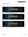
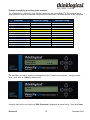
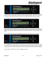
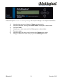
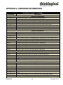
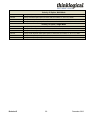
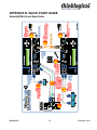
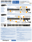
1
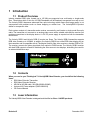
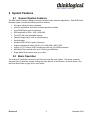
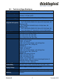
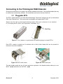
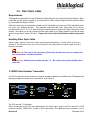
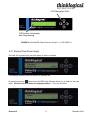
Copyright Notice
Copyright © 2012. All rights reserved. Printed in the U.S.A.
Thinklogical® LLC
100 Washington Street
Milford, Connecticut 06460 U.S.A.
Telephone: 1-203-647-8700
All trademarks and service marks are property of their respective owners.
Subject: VelocityRGB Video Extension System-9, -10 and -12
Revision: D, December 2012
Revision D
i
December 2012
Table of Contents
PREFACE............................................................................................................................................... iv
Conventions Used in this Manual .........................................................................................................iv
1 Introduction ....................................................................................................................................... 1
1.1 Product Overview ......................................................................................................................... 1
1.2 Contents ....................................................................................................................................... 1
1.3 Laser Information ......................................................................................................................... 1
1.4 Theory of Operation ..................................................................................................................... 2
MRTS Technology ........................................................................................................................... 2
2 System Features ................................................................................................................................ 3
2.1 General System Features ............................................................................................................. 3
2.2 Basic Operation ............................................................................................................................ 3
2.3 Technical Specifications ............................................................................................................... 5
3 Connecting to the Velocity Extenders.............................................................................................. 6
3.1 Pluggable SFP+ ........................................................................................................................... 6
3.2 Fiber Optic Cable ......................................................................................................................... 7
Requirements ................................................................................................................................... 7
Handling Fiber Optic Cable .............................................................................................................. 7
Installing Fiber into Input/Output Cards ............................................................................................ 7
Removing Fiber from Input/Output Cards ......................................................................................... 7
The CPU and the TX Connector ....................................................................................................... 8
Modifying the Analog RGB Video Parameters .................................................................................. 8
3.3 Transmitter and Receiver ......................................................................................................... 9
3.4 AC Power Supply ..................................................................................................................... 10
4 Set-Up and Installation .................................................................................................................... 10
4.1 Order of Installation Events ........................................................................................................ 10
4.2 Firmware Upgrades .................................................................................................................... 10
4.2 Front Panel Usage ........................................................................................................................... 10
4.2.1 General Front Panel Usage..................................................................................................... 11
4.2.2 Saving Changes………………………………………………………………………………………….15
4.2.3 Restoring Factory Defaults ........................................................................................................ 16
Load factory default video configurations. .......................................................................................... 16
4.2.4 Naming the Transmitter Unit...................................................................................................... 17
4.2.5 Modifying an Existing Video Modeline ....................................................................................... 18
Modification to support the alternate timing. ....................................................................................... 18
5 Regulatory & Safety Compliance.................................................................................................... 22
5.1 Safety Requirements .................................................................................................................. 22
Symbols found on the product ........................................................................................................ 22
Regulatory Compliance .................................................................................................................. 22
North America ................................................................................................................................ 22
Australia & New Zealand ................................................................................................................ 22
European Union ............................................................................................................................. 22
5.2 Standards with Which Our Products Comply .............................................................................. 23
5.3 Supplementary Information ........................................................................................................ 23
Product Serial Number ................................................................................................................... 24
Connection to the Product .............................................................................................................. 24
Revision D
ii
December 2012
6 How to Contact Us ........................................................................................................................... 25
6.1 Customer Support ...................................................................................................................... 25
Website .......................................................................................................................................... 25
Email .............................................................................................................................................. 25
Telephone ...................................................................................................................................... 25
Fax ................................................................................................................................................. 26
6.2 Product Support ......................................................................................................................... 26
Warranty ........................................................................................................................................ 26
Return Authorization....................................................................................................................... 26
Our Address ................................................................................................................................... 27
APPENDIX A: ORDERING INFORMATION .......................................................................................... 28
APPENDIX B: QUICK START GUIDE .................................................................................................. 30
Revision D
iii
December 2012
PREFACE
Conventions Used in this Manual
Throughout this manual you will notice certain conventions that bring your attention to important
information. These are Notes and Warnings. Examples are shown below.
Note: Important Notes appear in blue text preceded by a yellow exclamation point
symbol, like this.
A note is meant to call the reader’s attention to helpful information at a point in the text that is relevant to
the subject being discussed.
Warning! All Warnings appear in red text, followed by blue text, and preceded by a
red stop sign, like this.
A warning is meant to call the reader’s attention to critical information at a point in the text that is relevant
to the subject being discussed.
Revision D
iv
December 2012
1 Introduction
1.1 Product Overview
Industry standard RGB video formats up to 165 MHz are supported over multi-mode or single-mode
fiber. Resolutions which fit into the 165 MHZ bandwidth will be flawlessly transported from end to end.
The Velocity RGB-9 harnesses advanced fiber optic technology which means that image quality is not
compromised with problems such as frame dropping or content loss. The VelocityRGB-12 product
allows for component video.
Each system consists of a transmitter and a receiver connected by multi-mode or single mode fiber optic
cable. The transmitter unit connects to an analog video source with a suitable cable and the receiver unit
provides connections to the display device. A +5V DC power supply is required on both the transmitter
and receiver.
The Velocity RGB-9 and Velocity RGB-12 require two fibers. The Velocity RGB-9 transmitter supports
RGB video formats up to 165MHz. In addition, the Velocity RGB-9 has a local RGB video display port on
the transmitter and is compatible with all Thinklogical Velocity fiber video receivers, whether RGB or DVI.
The receiver converts the video signal back from optical to RGB formats. The Velocity RGB-9 receiver
with dual RGB outputs is offered for distributing the video source to two displays, eliminating the need for
an external distribution amp.
1.2 Contents
When you receive your Thinklogical™ VelocityRGB Video Extender, you should find the following
items:
•
•
•
•
•
RGB Video Extender Transmitter
RGB Video Extender Receiver
HD15M to HD15M cable, 2M (CBL000020-002MR)
Universal AC Power adapters (PWR-000022-R)
CD Product Manual
1.3 Laser Information
The VelocityRGB Video Extender is designed and identified as Class 1 LASER products.
Revision D
1
December 2012
1.4 Theory of Operation
MRTS Technology
Thinklogical® VelocityRGB Extenders utilize breakthrough, patent-pending technology for transmission
and reception of DVI, keyboard, mouse, and high-speed data peripherals. This technology, known as
Multi Rate Transmission System (MRTS), provides end-to-end data transmission with unparalleled
performance. This new, unique optic platform enables multiple data streams to be transmitted long
distances over single or multiple fibers with complete reconstruction of the data clock at the destination
end point. The result is perfect synchronization with each transmitted stream.
MRTS is a highly reliable technology and delivers powerful benefits to our customers when combined
with our new SFP+ optics. The new MRTS Technology has the ability to transport every frame of a 1920
x 1200 @ 60Hz (or higher) video stream with no compression, along with all desktop peripherals
(keyboard, mouse, etc., including 480Mbps USB 2.0) with no perceptible latency. Moreover, these
signals can be transmitted distances from just a few meters up to 40 kilometers over single-mode or
multi-mode fibers.
MRTS allows for traditional AV implementations and video routing to be incorporated into the same
switch fabric, providing greater value, flexibility, performance and security. Additional unique capabilities
include the ability to support 6.25Gbps bandwidth per stream, between 50% and 100% higher than our
nearest competitors (typically 1.485Gbps to 3.2Gbps). This is significant because a single DVI stream
requires a 5.4Gbps data rate to accommodate the 165MHz of video data. Our competitor’s lower
bandwidth capability is generally manifested in either dropped frames or lower resolution associated with
compressing schemes. Not so with MRTS Technology.
Revision D
2
December 2012
2 System Features
2.1
General System Features
The RGB Video Extender is designed for high resolution video extension applications. Each RGB Video
Extender system includes the following common features:
• All copper cabling is industry standard
• Units are stand alone and rack mountable (brackets included)
• Local RGB Display port on transmitter
• RGB supported to 1600 x 1200, 1920x1080
• Front LCD with user adjustable settings
• Flawless image quality, with no frame dropping
• Small package
• Standard VGA (HD15) Copper Connectors
• Supports Component Video (Velocity 12)- 1920x1080i, 480P, 720P
• Velocity 12 TX Converts YPbPr component video into 4:4:4 RGB colorspace
• Multi Mode Fiber extends video up to 1000m (type OM4 fiber)
• Single Mode Fiber extends video up to 10km
2.2 Basic Operation
The Velocity-9 Transmitter connects to the Receiver using fiber optic cables. The source computer
connects to the Transmitter and the viewing and audio devices to the Receiver, as shown below. See
the Quick Start Guide on page 29 for more details.
Revision D
3
December 2012
Revision D
4
December 2012
2.3
Technical Specifications
Storage Temperature
-20 to 70 o C (-4 to 158 o F), 10 to 90% RH, non-condensing
Power Consumption
Transmitter: <15 Watts, typical
Receiver: <15 Watts, typical
Front Panel Display
Transmitter and Receiver: 2 x 24 Liquid Crystal Display
Copper Cables
(Supplied with system)
Velocity 9 TX
Qty 1 CBL000020-002MR HD15 (M) to HD15 (M) Cable, 2M
Velocity 10 TX
Qty 1 CBL000013-002MR DVI(M) to DVI(M) Cable, 2M
Velocity 12 TX
Qty 1 CBL000020-002MR HD15 (M) to HD15 (M) Cable, 2M
Qty 2 CBL000041 6FT VGA/HD15 to 3-RCA COMPONENT
Single Mode or Multi Mode, depending upon model
Up to 65 meters with Type OM1
Up to 350 meters with Type OM2
Up to 650 meters with Type OM3
Up to 1000 meters with Type OM4
Velocity 9
Height: 1.19” (3.016cm)
Depth: 10” (25.4cm)
Width: 6.49” (16.5cm) Weight: <1lb (0.45kg) Each
Shipping Weight: 4lbs (1.81kg) Pair
Velocity 10
Height: 1.19” (3.016cm)
Depth: 10” (25.4cm)
Width: 6.49” (16.5cm) Weight: <1lb (0.45kg) Each
Shipping Weight: 4lbs (1.81kg) Pair
Velocity 12
Height: 1.19 inches (3.016 cm)
Depth: 10 inches (25.4 cm)
Width: 6.49 inches (16.5 cm)
Weight: <1 lb (0.45 kg) each
Shipping Weight: 4 lbs (1.81 kg) (one Velocityrgb System-12
transmitter and one Velocity receiver)
(Tolerance: ± .039"; .1000 mm)
Optical Cable
Optical Distance
Dimensions
Operating Temp
and Humidity
0° to 50°C (32° to 122 °F), 5% to 95% RH, non-conde nsing
Supply Voltage
AC/DC Adapter Universal Input 90-264 VAC
Compliance
Approvals for US, Canada, and European Union (pending)
12 months from date of shipment. Extended warranties
available.
Warranty
Revision D
5
December 2012
Connecting to the Thinklogical RGB Extender
All physical connections to the product use industry-standard connectors. Non-supplied cables that may
be needed are commercially available. All connections are found on the rear of the unit.
3.1 Pluggable SFP+
The SFP+ Optical Module is an 8Gbs Short-Wavelength Transceiver designed for use in bi-directional
Fiber Optic Channel links. The modules are hot-pluggable and operate with 3.3VDC.
Always use dust caps to protect against damage when a fiber optic connector is not attached
to its coupling device (fiber optic equipment, bulkheads, etc.)
Dust Plug
Figure 11: SFP+ Module; it is good practice to install dust plugs in unused SFP+s
Each SFP+ module is locked into its enclosure with a built-in latch handle that can be opened for
removal or locked for installation.
Figure 12a: SFP+ latch closed
Figure 12b: SFP+ latch open
The latch handle spans the two LC ports and arrows printed on the handle indicate which port is an
INPUT (
) and which is an OUTPUT (
).
Revision D
6
December 2012
3.2 Fiber Optic Cable
Requirements
Thinklogical recommends SX+ Laser Enhanced (50µm) fiber for your Velocity Extension System. Multimode fiber has the ability to extend up to a maximum of 1000m, where Single-mode fiber has the ability
to extend distances beyond 1000m.
Fiber optic cable must run between the location of the Transmitter unit (near your CPU) and the Receiver
unit (near your desktop devices). The standard multi-mode fiber optic cable must be 50 micron,
terminated with an SC, ST or LC type fiber optic connector and no longer than 3280 running feet (1000
meters). Be careful not to kink or pinch the fiber optic cable as it is being installed, and keep all bend
radii to no less than 3 inches (76.2mm). Please refer to the Quick Start Guide included in Appendix
B.
Handling Fiber Optic Cable
Unlike copper cabling, fiber optic cable requires special handling. A small speck of dust or a
scratch to the ferrule tip (the end of the connector) can attenuate the optical signal so that it
becomes unusable.
Warning! The ends of the connectors (the ferrule) should never come in contact with
any foreign object, including fingertips.
Warning! Minimum bend radius must be 1.5”. Be careful not to pinch the fiber when
using ties.
3.3 RGB Video Extender Transmitter
If a DVI-A connection from the source is required, standard adapters are available from Thinklogical and
third party suppliers to make other combinations. (See Table 3)
FIGURE 7: Velocity RGB-9 Transmitter
The CPU and the TX Connector
Video connections to the CPU are made between the video output card of the CPU and the TX VGA
connector labeled “FROM CPU” (closest to fiber connectors). The additional video connector is for a
Revision D
7
December 2012
local administrator to view the video output at the TX unit.
The analog VGA inputs are converted to a fiber optic suitable form and transmitted to the RX unit.
Modifying the Analog RGB Video Parameters
It is possible for one resolution to have different video timings, which could cause a less than perfect
display on the remote side. For example, take 1280x1024x60 Hz. The VESA standard has 1688 pixels
in one line, whereas a SGI format has 1680 pixels. The transmitter lookup table is configured for the
VESA standard, but can be easily modified to support the SGI format. (Refer to Section 7.2.6 for step by
step instructions.)
FIGURE 14
FIGURE 15
FIGURE 14: 1280x1024x60 on an SGI computer with the PLLDIV set at 1688 (default value).
the columns.
Notice
FIGURE 15: 1280x1024x60 on an SGI computer with the PLLDIV modified to 1680.
The below table lists supported analog (VGA) resolutions:
Thinklogical™ Veloctiy supported resolutions
Active Resolution
Pixels
640
640
640
640
640
Revision D
Lines
448
480
480
480
480
Total
Lines
Vertical
Freq(Hz)
Horizontal
Freq(kHz)
Pixel Clock
Freq(MHz)
472
525
520
500
509
66
60
72
75
85
31.2
31.5
37.9
37.5
43.3
25
25.175
31.5
31.5
36
8
Video Standard
Honeywell
Industry Standard
VESA
VESA
VESA
December 2012
720
800
800
800
800
800
1024
1024
1024
1024
1280
1280
1280
1280
1280
1280
1280
1280
1280
1366
1400
1400
1400
1400
1440
1440
1600
1680
1920
1920
1920
400
600
600
600
600
600
768
768
768
768
720
720
800
1024
1024
1024
1024
1024
1024
768
1050
1050
1050
1050
900
900
1200
1050
1080
1080
1080
449
625
628
666
625
631
800
806
800
808
750
750
828
1066
1066
1082
1066
1072
1063
795
1090
1080
1089
1099
932
934
1250
1089
1125
1125
1125
70
56
60
72
75
85
50
60
75
85
50
60
60
50
60
60
75
85
96
60
50
60
60
96
60
60
60
60
25
50
60
31.5
35.1
37.9
48.1
46.9
53.7
40
48.4
60
68.7
37.5
45
49.7
52.8
64
64.8
80
91.1
102
47.7
54.5
64.8
65.3
105.4
55.8
55.9
75
65.3
28.12
56.25
67.5
28.32
36
40
50
49.5
56.25
53.44
65
78.75
94.5
74.25
74.25
83.46
89.55
108
108.88
135
157.5
163.277
85.5
94.61
120.78
121.75
164.5
106.4
106.5
162
146.25
74.25
148.5
148.5
Industry Standard
VESA
VESA
VESA
VESA
VESA
Folsom
VESA
VESA
VESA
Folsom
CEA-861-E
VESA GTF
Folsom
VESA
Discreet
VESA
VESA
SGI Onyx2
VESA GTF
Folsom
VESA CVT-RB
VESA
SGI Stereo
VESA GTF
VESA DMT
VESA
VESA DMT
Folsom
Folsom
CEA-861-E
Supported Analog VGA Resolutions
*In the Velocity 12 product 480p, 720p and 1080i resolutions are supported at 60Hz.
3.3 RGB Video Extender Receiver
The receiver connects to your display/monitor video Input using a VGA, HD15 (if monitor has a
VGA/HD15 connector). These cables are provided with unit. Standard adapters are available from
Thinklogical and third party suppliers if necessary to make other connections.
Revision D
9
December 2012
FIGURE 22: Velocity RGB-9 Receiver
3.4 AC Power
AC Power Supply
Two power supply adapters (part number PWR-000022-R) are included.
Universal Input: 100 – 240 VAC 50/60Hz Nominal
Continuous Short Circuit Protection
Over Voltage Protection
Optional AC adaptors to fit various international standards
AC Power Supply (PN: PWR-000022-R) shown with international AC adaptors
4 Set-Up and Installation
4.1 Order of Installation Events
Please refer to the Quick Start Guide included with your products for detailed instructions. The
Quick Start Guide is also available in Appendix A.
4.2 Firmware Upgrades
Firmware upgrades are available from Thinklogical. Please call us for technical assistance at (203) 6478700.
4.2 Front Panel Usage
Revision D
10
December 2012
LCD Navigation Pad
enter
Powered by
MRTS
Technology
Velocityrgb
Video Extension System - 9
Receiver
LCD System Information
and Programming
FIGURE 28: VelocityRGB Video Extension System – 9, LCD DISPLAY
4.2.1 General Front Panel Usage
Once the unit is powered up, the initial display is shown as follows:
Thinklogical
Velocity TX9
vxx.xx
This displays the device type and revision of the base unit.
By pressing the arrow
(down) keys, the RGB Video Extender allows you to enter into the main
menu. All main root menu items are displayed with an *. They are as follows:
*System
Revision D
11
December 2012
*DDC
*Video
*Enable Component.
Video
YES
Once an
* root menu item is displayed, you can then use the
(left) or
(right) arrow keys to review settings
or make changes, if allowed. The RGB Video Extender menu functionality is as follows:
Revision D
12
December 2012
Some menu options may not be available on some models
Display
Modifiable
*System
LS Connected
TX Ctrl Name
Load Defaults
Store Values
TX Control
RX Control
FPGA Version
Serial Number
Aud Reset En
SFP Loss of Signal
channel. Value =
Description
NO
TX Only
YES
YES
NO
NO
NO
YES
YES
NO
An indication of the fiber status from the TX to RX.
Name entered on TX unit is displayed on RX unit.
Loads factory default video configurations.
Store video configurations.
Revision of the TX control firmware.
Revision of the RX control firmware.
Revision of the FPGA code
Serial Number of unit.
Resets the audio sync circuitry
An indication of fiber status on the extender Receive
0 if signal is received, 1 if signal is missing.
Debug Values
YES
Factory Use Only.
___________________________________________________________________________________________
______________
*DDC – To be implemented at a later date
DDC PROM Emula. Mode
YES
Options are Dynamic, Static and Passthru.
In Dynamic mode, the DDC of the monitor connected to the RX is
read and stored on the TX. The CPU is informed of a change in
DDC and the monitor is read. This is useful when the CPU can be
turned on without a connection to the RX. Static mode is used to
maintain the current DDC regardless of monitor changes at the
RX. Pass-thru acts as a wire between the TX and RX and no
emulation takes place.
Load Default DDC
mode to
YES
Loads the default EDID table into the TX and changes the
Acquire DDC
stores it
Static.
Gets the EDID table from the monitor attached to the RX and
YES
Force DDC mode
digital.
YES
in the TX.
Sets the EDID Video Input Signal Type to either analog or
* Video
VGA Connected
Resolution input
Hor. Freq
Auto Phase
PLL Total
No
No
No
Yes
Yes
An indication of whether VGA video is input to the Vis TX
Active pixels x active lines vertical rate
Horizontal frequency
Automatically adjust the Sampling Phase to the best setting
The total pixel count in one line. Consists of Horizontal active
pixels +
HSOUT Width
DE Start
DE Width
Line Start
measured
Yes
Yes
Yes
Yes
Horizontal blanking pixels
Horizontal sync (Hsync) of video, measured in pixels
Horizontal back porch (Hpb) of video, measured in pixels
Total active pixels in one line
Vertical back porch (Vbp) + Vertical sync (Vsync) of video,
in lines
Revision D
13
December 2012
Line Width
NativeH
Use
Yes
No
NativeV
input. Use the
No
ISL Sync Status
NO
ISL Sync Activity
Video 1 cnt
Video 2 cnt
Enable Component Video
No
No
Revision D
The number of visible lines
For use by Tech support to determine horizontal frequency input.
NO
Yes
the following formula to calculate the frequency:
NativeH * 16
For use by Tech support to determine vertical frequency
following formula to calculate the frequency:
(10,000,000/NativeV)/16
For use by Thinklogical support. Measures sync selection and
sync polarity
For use by Thinklogical support. Measures sync activity
Internal use only.
Internal use only.
Enables component video resolutions
14
December 2012
4.2.2 Saving Changes
Save video configurations so that after powering up, the device can recall customer video
settings.
Thinklogical
VelocityTX9
vxx.xx
Using the down arrow, scroll down to *System as shown below.
*System
Using the right arrow, scroll right until Store Values is displayed as shown below then press enter.
Store Values
Yes/No=
NO
Using the up arrow or down arrow scroll until Yes appears as shown below. Then press enter.
Revision D
15
December 2012
Store Values
Yes/No =
YES
Using the right arrow or left arrow, scroll until you return to the *System menu option. Using up arrow or
down arrow, scroll until you get back to the Thinklogical screen.
4.2.3 Restoring Factory Defaults
Load factory default video configurations.
Using the down arrow, scroll down to *System as shown below.
*System
Using the right arrow button, scroll right until Load Defaults is displayed as shown below. Then press
enter.
Load Defaults
Yes/No=
NO
Using the up arrow or down arrow scroll until Yes appears as shown below. Then press enter.
Revision D
16
December 2012
Load Defaults
Yes/No=
YES
Follow the steps in Section 4.3.2 Saving Changes to save your changes.
4.2.4 Naming the Transmitter Unit
Modify the name of the unit through the Transmitter. The name entered on the Transmitter will
display on the Receiver unit.
Using the arrow down button, scroll down to *System as shown below.
*System
Using the right arrow, scroll right until Tx Ctrl is displayed as shown below. Then press enter.
Tx Ctrl
Name=
Revision D
TXUnit01
17
December 2012
Using the right or left arrow, scroll until the blinking cursor is under the letter/number you want to change.
Tx Ctrl
Name=
TXUnit01
Using the up or down arrow, scroll (holding down the up or down arrow will scroll faster) until you find the
appropriate letter/number. Then press enter.
Tx Ctrl
Name=
TXUnit11
Using the right or left arrow, scroll to return to the *System menu option.
*System
Follow the steps in Section 2.7.2 Saving Changes to save your changes. The steps are listed below:
1. Using the down arrow, scroll down to *System as shown below.
2. Using the right arrow, scroll right until Store Values is displayed as shown below. Then
press enter.
3. Using the up or down arrow scroll until Yes appears as shown below. Then press enter.
4. Using the right or left arrow, scroll to return to the *System menu option.
5. Using up or down arrow scroll until you get to the Thinklogical screen.
4.2.5 Modifying an Existing Video Modeline
Modification to support the alternate timing.
Revision D
18
December 2012
Example of modifying an existing video modeline:
The VESA timing for 1280x1024_60Hz (SXGA) is loaded into the VelocityRGB 9 TX. The modeline can be
easily modified to support the alternate timing listed in the table below. Modifiable differences are highlighted.
Parameter
Supported Timing
Resolution
Pixel Clock (MHz)
Horizontal Frequency (kHz)
Vertical Refresh (Hz)
Horizontal Total Pixels
Horizontal Active (Pixels)
Horizontal Front Porch(Pixels)
Horizontal Sync Width(Pixels)
Horizontal Back Porch(Pixels)
Vertical Total Lines (Lines)
Vertical active lines (Lines)
Vertical Front Porch (Lines)
Vertical sync (Lines)
Vertical Back Porch (Lines)
1280x1024_60
108
63.98
60
1688
1280
48
112
248
1066
1024
1
3
38
Alternate Timing
1280x1024_60 SGI Onyx
107.352
63.9
60
1680
1280
40
120
240
1065
1024
3
3
35
Thinklogical
VelocityTX9
Vxx.xx
The resolution you wish to modify must be applied to the TX video input connector. Using the arrow
down, scroll down to *Video as shown below.
*Video
Using the right arrow, scroll right until VGA Connected is displayed as shown below. Then press enter.
Revision D
19
December 2012
PLL Total
1688
The Horizontal Pixel needs to be changed to 1680 to reflect the Alternate Timing listed on Table 4.
Move the cursor under the number you want to change by pressing the right or left arrow. Use the arrow
up or down to increment or decrement the number. Once number is entered correctly, press enter.
Using the right arrow, scroll right until DE Start is displayed as shown below. Then press enter.
DE Start
248
The Horizontal Backporch (Pixels) needs to be changed to 240 to reflect the Alternate Timing listed on
Table 4. Move the cursor under the number you want to change by pressing the right or left arrow. Use
the arrow up or down to increment or decrement the number. Once number is entered correctly, press
enter.
Using the right arrow, scroll right until Line Start is displayed as shown below. Then press enter.
The Vertical Backporch (Pixels) needs to be changed to 35 to reflect the Alternate Timing listed on Table
4. Move the cursor under the number you want to change by pressing the right or left arrow. Use the
arrow up or down to increment or decrement the number. Once number is entered correctly, press enter.
Using the right or left arrow, scroll to return to *Video menu option.
Revision D
20
December 2012
*Video
Follow the steps in Section 2.7.2 Saving Changes to save your changes. The steps are listed below:
1.
2.
3.
4.
5.
6.
7.
Revision D
Using the down arrow, scroll down to *System as shown below.
Using the right arrow, scroll right until Store Values is displayed as shown below.
Then press enter.
Using the up or down arrow scroll until Yes appears as shown below.
Then press enter.
Using the right or left arrow, scroll to return to the *System menu option.
Using up or down arrow scroll until you get to the Thinklogical screen.
21
December 2012
5 Regulatory & Safety Compliance
5.1 Safety Requirements
Symbols found on the product
Markings and labels on the product follow industry-standard conventions. Regulatory markings found on
the products comply with domestic and many international requirements.
Regulatory Compliance
Thinklogical®’s Velocity Extension System is designed and made in the U.S.A. The Velocity Extension
system has been tested by a certified testing laboratory and found to be compliant with the following
standards (both domestic USA and many international locations):
North America
Safety
ANSI/UL60950-1: 1st Edition (2003)
CAN/CSA C22.2 No. 60950-1-03
LASER Safety
CDRH 21CFR 1040.10
Class 1 LASER Product
Electromagnetic Interference
FCC CFR47, Part 15, Class A
Industry Canada ICES-003 Issue 2, Revision 1
Australia & New Zealand
This is a Class A product. In a domestic environment this product may cause radio interference, in
which case the user may be required to take adequate measures.
European Union
Declaration of Conformity
Manufacturer’s Name & Address:
Thinklogical®
100 Washington Street
Milford, Connecticut 06460 USA
Telephone 1-203-647-8700
These products comply with the requirements of the Low Voltage Directive 72/23/EEC and the EMC
Directive 89/336/EEC.
Revision D
22
December 2012
5.2 Standards with Which Our Products Comply
Safety
CENELEC EN 60950-1, 1st Edition (2001)
LASER Safety
IEC60825:2001 Parts 1 and 2
Class 1 LASER Product
Electromagnetic Emissions
EN55022: 1994 (IEC/CSPIR22: 1993)
EN61000-3-2/A14: 2000
EN61000-3-3: 1994
Electromagnetic Immunity
EN55024: 1998 Information Technology Equipment-Immunity Characteristics
EN61000-4-2: 1995 Electro-Static Discharge Test
EN61000-4-3: 1996 Radiated Immunity Field Test
EN61000-4-4: 1995 Electrical Fast Transient Test
EN61000-4-5: 1995 Power Supply Surge Test
EN61000-4-6: 1996 Conducted Immunity Test
EN61000-4-8: 1993 Magnetic Field Test
EN61000-4-11: 1994 Voltage Dips & Interrupts Test
5.3 Supplementary Information
The following statements may be appropriate for certain geographical regions and might not apply to
your location.
This Class A digital apparatus meets all requirements of the Canadian Interference-Causing
Equipment Regulations.
Cet appareil numérique de la classe A respecte toutes les exigencies du Règlement sur le matérial
brouilleur du Canada.
Warning! This is a Class A product. In a domestic environment, this product may
cause radio interference, in which case the user may be required to take corrective
measures.
Revision D
23
December 2012
Note: This equipment has been tested and found to comply with the limits for a
Class A digital device, pursuant to part 15 of the FCC Rules. These limits are
designed to provide reasonable protection against harmful interference when the
equipment is operated in a commercial environment. This equipment generates,
uses and can radiate radio frequency energy and, if not installed and used in
accordance with the instruction manual, may cause harmful interference to radio
communications in which case the user may be required to take adequate corrective
measures at their own expense.
Note: This Class A digital apparatus complies with Canadian ICES-003 and has been
verified as being compliant within the Class A limits of the FCC Radio Frequency
Device Rules (FCC Title 47, Part 15, Subpart B CLASS A), measured to CISPR 22:
1993 limits and methods of measurement of Radio Disturbance Characteristics of
Information Technology Equipment.
Note: The user may notice degraded audio performance in the presence of
electromagnetic fields.
Note: If using a keyboard that is noise susceptible, a ferrite ring on the keyboard
cable may be needed to comply with Immunity Requirements
Product Serial Number
Thinklogical® products have a unique serial number, imprinted on an adhesive label that is fixed to the
bottom of the chassis. The serial number includes a date-code. The format for the date-code is 2 digits
for the month, 2 digits for the day and 2 digits for the year, plus two or three digits for a unique unit
number. This serial number is also found on the original shipping carton.
Connection to the Product
Connections and installation hardware for our products use industry-standard devices and methods. All
wiring connections to the customer equipment are designed to minimize proprietary or customized
connectors and cabling. Power connections are made with regionally appropriate power cords and
approved methods.
Revision D
24
December 2012
6 How to Contact Us
6.1 Customer Support
Thank you for choosing a Thinklogical® product for your application. We appreciate your business and
are dedicated to helping you successfully use our product. Thinklogical® is here to help you.
Thinklogical® is an engineering company and you will receive the information you require directly from
our most knowledgeable engineers. We believe that the first line of support is the design engineer that
developed the product. Therefore, your questions will be handled promptly by our in-house engineers
who are most familiar with your products.
To contact Thinklogical®, use the following telephone numbers and internet-based methods.
Website
Check out our website for current product offerings, support information and general information about
all of the products we offer.
Our internet website offers product information on all current systems, including technical specification
sheets and installation guides (for viewing online or for download), product diagrams showing physical
connections and other information you might need.
Internet: www.thinklogical.com
Note: Most online documents are stored as Adobe Acrobat “PDF” files. If you do not have
the Adobe Acrobat reader needed to view PDF files, visit www.adobe.com for a download.
Email
Thinklogical® is staffed Monday through Friday from 8:30am to 5:00pm, Eastern Time Zone. We will
try to respond to your email inquiries promptly, use the following email addresses for your different
needs:
[email protected] – Information on Thinklogical® and our products.
[email protected] – Sales Department - orders, questions or issues.
[email protected] – Product support, technical issues or questions, product
repairs and request for Return Authorization.
Telephone
Telephone Sales: Contact our expert sales staff via telephone in Milford, CT at 1-203-647-8700 or if in
the continental US, you may use our toll-free number 1-800-291-3211. We are here Monday through
Friday from 8:30am to 5:00pm, Eastern Time Zone. Ask for your representative’s direct dial phone
number when you call.
Revision D
25
December 2012
Telephone Product Support: Contact Product Support via telephone in Milford, CT at 1-203-647-8700.
The support lines are manned Monday through Friday, 8:30am to 5:00pm, Eastern Time Zone.
International Sales: Please contact our US sales staff in Milford, CT at 1-203-647-8700. We are here
Monday through Friday, 8:30am to 5:00pm, Eastern Time Zone (same as New York City). If leaving a
voice message please provide a “best time to call back” so we may reach you at your convenience.
Our switchboard attendant will direct your call during regular business hours. We have an automated
attendant answering our main telephone switchboard after regular business hours and holidays. You
can leave voice messages for individuals at any time. Our Sales Representatives have direct numbers
to speed up your next call to us.
Fax
Our company facsimile number is 1-203-783-9949. Please indicate the nature of the fax on your cover
sheet and provide return contact information.
6.2 Product Support
Thinklogical’s® support personnel are available Monday through Friday from 8:30am to 5:00pm,
Eastern Time Zone. If your application requires assistance at some time outside of our normal business
hours, please contact us beforehand and we will do our best to make arrangements to help you with your
Thinklogical® products.
Warranty
Thinklogical® warrants this product against defects in materials and workmanship for a period of one year
from the date of delivery. Thinklogical® and its suppliers disclaim any and all other warranties.
Note: Thinklogical® Inc. products carry a one year warranty, with longer term available at
time of purchase on most products. Please refer to your product invoice for your products
Warranty Terms & Conditions.
Defect remedy shall be the repair or replacement of the product, provided that the defective product is
returned to the authorized dealer within a year from the date of delivery.
If you wish to return your device, contact the Thinklogical® authorized dealer where you purchased the
device, or if you purchased directly, call Thinklogical® at 1-800-291-3211 (USA).
Return Authorization
In the event you must return a product to Thinklogical® directly, please contact Customer Support at
1-800-291-3211 or 1-203-647-8700. Customer Support will ask you to describe the problem and will
issue you a Return Merchandise Authorization number (RMA#). Pack the device in its original box, if
possible, and return it with the RMA# printed on the outside of the box.
Revision D
26
December 2012
Note: DO NOT return a product to Thinklogical® without a Return Material Authorization.
Return address for products with Return Material Authorization:
Thinklogical®, LLC
Attn: RMA#
100 Washington Street
Milford, CT 06460 USA
PH: 1-800-291-3211 (USA only)
Our Address
If you have any issue with a product, have product questions or need technical assistance with your
Thinklogical® system, please call us at 1-800-291-3211 (USA only) or 1-203-647-8700 and let us help.
If you’d like to write us, our mailing address is:
Thinklogical® LLC.
100 Washington Street
Milford, CT 06460 USA
Revision D
27
December 2012
APPENDIX A: ORDERING INFORMATION
Thinklogical's VelocityRGB Extenders
Part Number
Description
Velocity 9 Part Numbers
VEL-AV0M09-LCRX
Velocity 9 RGB RX, RGB HV, AUX VGA Output, Serial, Audio, MM, LC
VEL-AV0M09-LCTX
Velocity 9 RGB TX, RGB HV, Local Display, Local VGA Port, Serial, Audio, MM, LC
VEL-AV0M09-LCRA
Velocity 9 RGB RX, RGB HV, AUX VGA Output, Serial, Separate Audio, MM, LC
VEL-AV0M09-LCTA
Velocity 9 RGB TX, RGB HV, Local Display, Local VGA Port, Serial, Separate Audio, MM, LC
VEL-AVRM09-LCRX
Velocity 9 RGB RX, RGB HV, AUX VGA Output, Serial, Audio, Redund Optics, MM, LC
VEL-AVRM09-LCTX
Velocity 9 RGB TX, RGB HV, Local Display, Local VGA Port, Serial, Audio, Redund Optics, MM, LC
VEL-AV0X09-LCRX
Velocity 9 RGB RX, RGB HV, AUX VGA Output, Serial, Audio, Multipath, MM, LC
VEL-AV0X09-LCTX
Velocity 9 RGB TX, RGB HV, Local Display, Local VGA Port, Serial, Audio, Multipath, MM, LC
VEL-AV0M12-LCTX
Velocity 12 RGB TX, RGB HV, Local Display/VGA Port, Component, Serial, Audio, MM, LC
VEL-AV0M12-LCTA
Velocity 12 RGB TX, RGB HV, Local Display/VGA Port, Component, Serial, Separate Audio, MM, LC
Velocity 12 RGB TX, RGB HV, Local Display/VGA Port, Component, Serial, Audio, Redund Optics, MM,
LC
Velocity 12 RGB TX, RGB HV, Local Display/VGA Port, Component, Serial, Audio, Multipath, MM, LC
Velocity 10 Part Numbers
VEL-AVRM12-LCTX
VEL-AV0X12-LCTX
Velocity 9/12 Optics, Multi-Mode
VOP-M04
Velocity 9/12 Optics Option for TX/RX, MM, Dual Fiber, 1000M, LC
VOP-M01
Velocity 9/12 Optics Option for TX/RX, MM, Dual Fiber, 1000M, SC/ST
VOP-M26
Velocity 9/12 Redund Optics Option for TX/RX, MM, Four Fibers, 1000M, LC
VOP-M22
Velocity 9/12 Redund Optics Option for TX/RX, MM, Four Fibers, 1000M, SC/ST
VOP-S11
Velocity 9/12 Optics Option for TX/RX, SM, Dual Fiber, 10KM, LC
VOP-S05
Velocity 9/12 Optics Option for TX/RX, SM, Dual Fiber, 10KM, SC/ST
VOP-S41
Velocity 9/12 Redund Optics Option for TX/RX, SM, Four Fibers, 10KM, LC
VOP-S15
Velocity 9/12 Redund Optics Option for TX/RX, SM, Four Fibers, 10KM, SC/ST
VOP-S41
Velocity 9/12 with Separate Audio Optics Option for TX/RX, SM, Four Fibers, 10KM, LC
VOP-S15
Velocity 9/12 with Separate Audio Optics Option for TX/RX, SM, Four Fibers, 10KM, SC/ST
VOP-S12
Velocity 9/12 Multipath Optics Option for TX/RX, SM, Three Fibers, 4KM, LC
VOP-S08
Velocity 9/12 Multipath Optics Option for TX/RX, SM, Three Fibers, 4KM, SC/ST
VEL-AV0M10-LCRX
Velocity 10 RGB RX, RGB HV, DVI-I, AUX VGA Output, Serial, Audio, MM, LC
VEL-AV0M10-LCTX
Velocity 10 RGB TX, RGB HV, DVI-I, Local Display, Local VGA Port, Serial, Audio, MM, LC
VEL-AV0M10-LCRA
Velocity 10 RGB RX, RGB HV, DVI-I, AUX VGA Output, Serial, Separate Audio, MM, LC
VEL-AV0M10-LCTA
Velocity 10 RGB TX, RGB HV, DVI-I, Local Display, Local VGA Port, Serial, Separate Audio, MM, LC
VEL-AVRM10-LCRX
VEL-AV0X10-LCRX
Velocity 10 RGB RX, RGB HV, DVI-I, AUX VGA Output, Serial, Audio, Redund Optics, MM, LC
Velocity 10 RGB TX, RGB HV, DVI-I, Local Display, Local VGA Port, Serial, Audio, Redund Optics,
MM, LC
Velocity 10 RGB RX, RGB HV, DVI-I, AUX VGA Output, Serial, Audio, Multipath, MM, LC
VEL-AV0X10-LCTX
Velocity 10 RGB TX, RGB HV, DVI-I, Local Display, Local VGA Port, Serial, Audio, Multipath, MM, LC
Velocity 9/12 Optics, Single-Mode
Velocity 10 Part Numbers
VEL-AVRM10-LCTX
Revision D
28
December 2012
Velocity 10 Optics, Multi-Mode
VOP-M19
Velocity 10 Optics Option for TX/RX, MM, Dual Fiber, LC, SC or ST, 1000M
VOP-M30
Velocity 10 Redund Optics Option for TX/RX, MM, Four Fibers, LC, SC or ST, 1000M
VOP-M14
Velocity 10 with Separate Audio Optics Option for TX/RX, MM, Four Fibers, LC, SC or ST, 1000M
VOP-M21
Velocity 10 Multipath Optics Option for TX/RX, MM, Three Fibers, LC, SC or ST, 1000M
Velocity 10 Optics, Single-Mode
VOP-S04
Velocity 10 Optics Option for TX/RX, SM, Dual Fiber, LC, SC or ST, 10KM
VOP-S06
Velocity 10 Redund Optics Option for TX/RX, SM, Four Fibers, LC, SC or ST, 10KM
VOP-S89
Velocity 10 Redund Optics Option for TX/RX, SM, Four Fibers, LC, SC or ST, 40KM
VOP-S06
Velocity 10 with Separate Audio Optics Option for TX/RX, SM, Four Fibers, LC, SC or ST, 10KM
VOP-S06
Velocity 10 Multipath Optics Option for TX/RX, SM, Three Fibers, LC, SC or ST, 4KM
VOP-S58
Velocity 10 Multipath Optics Option for TX/RX, SM, Three Fibers, LC, SC or ST, 40KM
Revision D
29
December 2012
APPENDIX B: QUICK START GUIDE
VelocityRGB-9 Quick Start Guide
Revision D
30
December 2012
VelocityRGB-10 Quick Start Guide
Revision D
31
December 2012
VelocityRGB-12 Quick Start Guide
Revision D
32
December 2012