1
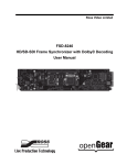
®
KVM Extenders
KVME 1000 & 1225
Series
KVM Extender (extends keyboard, VGA/RGB
video, DVI, mouse, serial & audio ports up to
3300 ft)
KVME 1xxx-ST: Duplex ST Fiber Connectors
KVME 1xxx-LC: Duplex LC Fiber Connectors
KVME 1xxx-SC: Duplex SC Fiber Connectors
USER’S MANUAL
VER. D.1 • OCT 2009
No part of this manual may be reproduced without permission
®
CyberResearch , Inc.
www.cyberresearch.com
25 Business Park Dr., Branford, CT 06405 USA
203-483-8815 (9am to 5pm EST) FAX: 203-483-9024
Revision #
Revision History
Description
Date of Issue
D
Initial Release
April 2005
D.1
Update specs / table
headings
October 26, 2009
®
CyberResearch KVM Extenders
KVME 1000 & 1225 Series
©Copyright 2009
All Rights Reserved.
October 2009
The information in this document is subject to change without prior notice
in order to improve reliability, design, and function and does not represent
a commitment on the part of CyberResearch, Inc.
In no event will CyberResearch, Inc. be liable for direct, indirect, special,
incidental, or consequential damages arising out of the use of or inability
to use the product or documentation, even if advised of the possibility of
such damages.
This document contains proprietary information protected by copyright.
All rights are reserved. No part of this manual may be reproduced by any
mechanical, electronic, or other means in any form without prior written
permission of CyberResearch, Inc.
Trademarks
“CyberResearch,” and “KVME 1000 & 1225 Series,” are trademarks of
CyberResearch, Inc. Other product names mentioned herein are used for
identification purposes only and may be trademarks and/or registered
trademarks of their respective companies.
• NOTICE •
CyberResearch, Inc. does not authorize any CyberResearch product for
use in life support systems, medical equipment, and/or medical devices
without the written approval of the President of CyberResearch, Inc. Life
support devices and systems are devices or systems which are intended
for surgical implantation into the body, or to support or sustain life and
whose failure to perform can be reasonably expected to result in injury.
Other medical equipment includes devices used for monitoring, data
acquisition, modification, or notification purposes in relation to life
support, life sustaining, or vital statistic recording. CyberResearch
products are not designed with the components required, are not subject
to the testing required, and are not submitted to the certification required
to ensure a level of reliability appropriate for the treatment and diagnosis of
humans.
CyberResearch, Inc.
25 Business Park Drive
Branford, CT USA
iii
P: (203) 483-8815; F: (203) 483-9024
www.cyberresearch.com
®
CyberResearch KVM Extenders
KVME 1000 & 1225 Series
Intentionally Blank
iv
©Copyright 2009 CyberResearch, Inc.
®
CyberResearch KVM Extenders
KVME 1000 & 1225 Series
Table of Contents
1. Introduction
1.1 KVME Series
1.2 Laser Information
1.3 System Features
1.4 Technical Specifications
2. Product Overview
2.1 Intended Application
2.2 Increased Security and Efficiency
2.3 Mounting the KVME Series Extender
2.3.1 Rack Mount or Desktop
2.3.2 Front Panel Display and Buttons
2.3.3 Convection Cooled
2.4 Connecting the KVME Series Extender
2.4.1 Fiber Cable
2.4.2 KVME Series Extender “Transmitter”
2.4.3 KVME Series Extender “Receiver”
2.5 Order of Installation Events
2.6 Firmware Upgrades
2.7 Front Panel Usage
2.7.1 General Front Panel Usage
2.7.2 Restoring Factory Defaults
2.7.3 Saving Changes
2.7.4 Utilizing Tablet Interface
2.7.5 Utilizing Apple keyboard
2.7.6 Modifying an Existing Video Modeline
3. Regulatory and Safety
3.1 Safety Requirements
3.1.1 Symbols found on the Product
3.1.1.1 Class 1M Laser Labeling
3.2 Regulatory Compliance
3.2.1 North America
3.2.2 Australia and New Zealand
3.2.3 European Union
3.2.3.1 Declaration of Conformity
3.2.3.2 Standards with which the Products Comply
3.2.4 Supplementary Information
4. How to Contact Us
4.1 Customer Support
4.1.1 Website
4.1.2 Email
4.1.3 Telephone
4.1.4 Fax
4.2 Product Support
4.2.1 Warranty
4.2.2 Return Authorization
4.2.3 Our Address
CyberResearch, Inc.
25 Business Park Drive
Branford, CT USA
v
P: (203) 483-8815; F: (203) 483-9024
www.cyberresearch.com
®
CyberResearch KVM Extenders
KVME 1000 & 1225 Series
1.1 KVME Series
e CyberResearch KVME Series is
E Series
Es
KVME Series
extenders
All models listed below are available with either SC-, ST- or LC- type connectors:
n.
KVME 1000
KVME 1225
1.2 LASER Information
LASER RADIATION
DO NOT VIEW DIRECTLY WITH OPTICAL INSTRUMENTS
CLASS 1M LASER PRODUCT
Caution:
In order to avoid possible exposure to laser energy, it is good practice to
attach the fiber optic cables prior to applying power to the KVM EXTENDER. If
the fiber optic cable should become disconnected, DO NOT attempt to look
into the cable or the panel mounted connector.
1
©Copyright 2009 CyberResearch, Inc.
®
CyberResearch KVM Extenders
KVME 1000 & 1225 Series
1.3 System Features
The KVME Series is designed for high resolution video extension applications. Each KVME
system includes the following common features:
! Remote access to entire “desktop” CPU connections up to 1000 meters. (3280 feet)
! All copper cabling is industry standard
! Uses multi-mode optical fibers
! Units are stand alone and rack mountable (brackets included)
! Digital transmission ensures signal integrity
! Supports PS2, Sun Legacy, USB keyboard and mouse (user can operate PS2 KB/MS, USB
KB/MS and SUN KB/MS simultaneously)
! Local video, keyboard and mouse at CPU end
! Duplex stereo audio
! RGB supported to 1920 x 1200
! DVI supported to 1920 x 1200
! BNC for stereo graphics emitter
! Front panel programmable for unique video formats
! Universal conversions between DVI and Analog RGB (DVI source to DVI or RGB display;
RGB source to DVI or RGB display) Not available on DVI only units!!
! Universal keyboard and mouse conversions (any of the three supported keyboard/mouse
types will work with CPU, regardless of source type)
CyberResearch, Inc.
25 Business Park Drive
Branford, CT USA
2
P: (203) 483-8815; F: (203) 483-9024
www.cyberresearch.com
®
CyberResearch KVM Extenders
KVME 1000 & 1225 Series
1.4 Technical Specifications
Storage Temperature
-20 to 70 o C (-4 to 158 o F), 10 to 90% RH, non-condensing
Supply Voltage
100-240 VAC, 50 -60 Hz, Universal
Power Consumption
Transmitter: <15 Watts, typical
Receiver: <15 Watts, typical
Heat Dissipation
< 60 BTU’s per hour
Laser Output Specifications
Wavelengths are 778, 800, 825, 850nm
Maximum laser power output in the fiber is 4.0 dBm
Audio
Line in Impedance: 550 Ohm
Line Out Impedence: 10K Ohm
Enclosure Dimensions
Approx. 17.25in x 14.17in x 1.75in high
(43.82cm x 35.99cm x 4.45cm high)
Weight
Transmitter: 11 lbs (4.99 kg)
Receiver: 11 lbs (4.99 kg)
Shipping Weight
Pair: 37 lbs (16.78 kg)
Transmitter: 23 lbs (10.43 kg)
Receiver: 23 lbs (10.43 kg)
Shipping Container
Dimensions
24 in x 22 in x 9.5 in high
(60.96 cm x 55.88 cm x 24.13 cm high)
AC Power Cable
IEC power cable (International connections may differ)
Panel Connectors
Refer to Section 2.4.2 and 2.4.3 to view Rear Panels of all KVM
Optical Cables:
2 Fiber or 3 Fiber cables are
available
Front panel Display
Multi-mode, 50 um or 62.5 um, SC-, ST- or LC- type
connectors. (Fiber cable is either customer supplied or can be ordered
from CyberResearch, Inc.)
3
Transmitter and Receiver: 2 x 24 Liquid Crystal Display
©Copyright 2009 CyberResearch, Inc.
®
CyberResearch KVM Extenders
KVME 1000 & 1225 Series
E Series from CyberResearch
E Series
Caution: The KVME Series is a Class 1M Laser Product that emits
near infrared light.
DO NOT VIEW DIRECTLY WITH MAGNIFYING OPTICAL INSTRUMENTS!
E Series
2.3 Mounting the KVME Series Extender
E Series
CyberResearch, Inc.
25 Business Park Drive
Branford, CT USA
4
P: (203) 483-8815; F: (203) 483-9024
www.cyberresearch.com
KVME 1000 & 1225 Series
®
CyberResearch KVM Extenders
2.3.1 Rack Mount or Desktop
The KVME Series Transmitter and Receiver may either be installed in an EIA-standard
19 inch rack (1U tall), or placed on a shelf or desktop. For shelf use, rubber feet are provided
and the rack mounted brackets may be removed. The KVME Series Transmitter and
Receiver chassis do not need to be opened or accessed. The sturdy metal case allows units
to be stacked, as required.
NOTE: Be sure to leave adequate ventilation space on both sides of the units, especially if
units are being stacked. Each rack mount bracket is held on by 4 screws. The brackets may
be positioned so that the unit sits forward or recesses in your rack. If the brackets are
removed or repositioned, it is not necessary to re-use the extra rack mount screws.
2.3.2 Front Panel Display and Buttons
The front-panel LCD display should be visible and accessible for system setup. The
front panel buttons are to configure special video settings and to review existing KVME
Series configurations. (Refer to FIG.11)
2.3.3 Convection Cooled
The KVME Series does not require special cooling or ventilation other than what is
normally provided in the equipment rack. No fan means that it does not add to the ambient
noise in your equipment room and it is less prone to equipment failure. Be sure not to block
the air vents on the sides of the unit, and leave space on both sides. If mounted in an
enclosed rack, it is recommended that the rack have a ventilation fan to provide adequate
airflow through the unit(s).
5
©Copyright 2009 CyberResearch, Inc.
®
CyberResearch KVM Extenders
KVME 1000 & 1225 Series
2.4 Connecting the KVME Series Extender
CyberResearch, Inc.
25 Business Park Drive
Branford, CT USA
6
P: (203) 483-8815; F: (203) 483-9024
www.cyberresearch.com
®
CyberResearch KVM Extenders
KVME 1000 & 1225 Series
2.4.2 KVME Series "Transmitter"
The Transmitter connecto to your CPU video port using a DVI-D to DVI-D cable. If a VGA
connection is required, standard adapters are available from CyberResearch and third
party suppliers to make other combinations.
FIG. 1
7
©Copyright 2009 CyberResearch, Inc.
®
CyberResearch KVM Extenders
KVME 1000 & 1225 Series
Transmitter Video Theory of Operation
The analog RGB video is digitized before transmitting the signals over fiber optic
cable. A high speed video analog to digital (A/D) converter is used for this purpose. When
an analog video source is connected to the transmitter, the horizontal and vertical
frequencies are measured and matched to a resolution in a lookup table where the rest of
the parameters to configure the A/D are stored. Once configured, the selected resolution,
vertical frequency, and horizontal frequency are then displayed on the Transmitter LCD
under the *video menu. If an unknown video source is connected to the extender, “N/A”
will be displayed on the *Video menu.
In order to reproduce the video signal with the greatest accuracy, the exact video
timings of the source must be known. Please refer to the “Supported Analog (VGA)
Resolutions” table for a list of pre-loaded resolutions. If you are using a video resolution not
listed in the table (N/A appears on the LCD), you will need to contact CyberResearch.
Please gather as much of the following information as possible before contacting us:
Pixel (Dot) Clock: _____________ MHz
Horizontal Frequency: __________ kHz
Vertical Frequency: ____________ Hz
Total Pixels per line: ___________ pixels
Active Pixel per line: __________ pixels
Horizontal Sync:
___________ pixels
Horizontal Back Porch: _________ pixels
Active Lines per frame: _________ lines
Vertical Back Porch: ___________ lines
NOTE: If you are creating your own video format, it is best to use the H and V timings listed in
the resolution table as a guideline. Then an existing format can be modified via the front
panel as opposed to waiting for one to be created by CyberResearch.
CyberResearch, Inc.
25 Business Park Drive
Branford, CT USA
8
P: (203) 483-8815; F: (203) 483-9024
www.cyberresearch.com
KVME 1000 & 1225 Series
®
CyberResearch KVM Extenders
The CPU and the TX Connector
Video connections to the CPU are made between the video output card of the CPU and
the TX DVI-D/DVI-I connector labeled “FROM CPU” (closest to fiber connectors). The additional
video connector is for a local administrator to view the video output at the TX unit.
The analog VGA inputs are converted to a fiber optic suitable form and transmitted to the
RX unit.
Modifying the Analog RGB Video Parameters
It is possible for one resolution to have different video timings, which could cause a less
than perfect display on the remote side. For example, take 1280x1024x60 Hz. The VESA
standard has 1688 pixels in one line, whereas a SGI format has 1680 pixels. The transmitter
lookup table is configured for the VESA standard, but can be easily modified to support the
SGI format. (Refer to Section 7.2.6 for step by step instructions.)
FIG.4
FIG.5
FIG.4: 1280x1024x60 on an SGI computer with the PLLDIV set at 1688 (default value). Notice
the columns.
FIG.5: 1280x1024x60 on an SGI computer with the PLLDIV modified to 1680.
* Not Supported by the Vis-000001
9
©Copyright 2009 CyberResearch, Inc.
®
CyberResearch KVM Extenders
Resolution
Pixels Lines
640
480
640
480
640
480
640
480
720
400
800
600
800
600
800
600
800
600
800
600
1024
768
1024
768
1024
768
1024
768
1024
768
1152
864
1152
900
1152
900
1280
768
1280
960
1280
960
1280
960
1280
1024
1280
1024
1280
1024
1280
1024
1280
1024
1280
1024
1280
1024
1400
1050
1400
1050
1400
1050
1400
1050
1600
1200
1600
1200
1600
1200
Vertical
Freq(Hz)
60
72
75
85
70
56
60
72
75
85
60
70
75
85
96s
75
66
76
60
60
85
96s
60
72
75
76
85
96s
96s
60
60
96s
96s
60
65
70
CyberResearch, Inc.
25 Business Park Drive
Branford, CT USA
KVME 1000 & 1225 Series
Supported Analog(VGA) Resolutions
Horizontal
Pixel Clock
Freq(kHz)
Freq(Mhz)
Video Standard
31.47
25.175
Industry Standard
37.86
31.500
VESA
37.5
31.500
VESA
43.27
36.000
VESA
31.47
28.322
Industry Standard
35.16
36.000
VESA
37.88
40.000
VESA
48.08
50.000
VESA
46.88
49.500
VESA
53.67
56.250
VESA
48.36
65.000
VESA
56.48
75.000
VESA
60.02
78.750
VESA
68.68
94.500
VESA
77.47
103.500
SGI
67.5
108.000
VESA
61.845
94.500
Sun
71.808
108.000
Sun
47.78
79.500
VESA
60
108.000
VESA
85.94
148.500
VESA
95.26
159.200
SGI
63.98
108.000
VESA
76.93
129.250
SGI
79.98
135.000
VESA
81.92
140.250
SGI
91.15
157.500
VESA
102.05
163.277
SGI
104.9
176.640
SGI
65.3
121.750
VESA
67.1
128.910
SGI
106.3
205.400
SGI
107.42
201.950
SGI
75
162.000
VESA
81.3
175.500
VESA
87.5
189.000
VESA
KVME KVME
1225 1000
Yes
Yes
Yes
Yes
Yes
Yes
Yes
Yes
Yes
Yes
Yes
Yes
Yes
Yes
Yes
Yes
Yes
Yes
Yes
Yes
Yes
Yes
Yes
Yes
Yes
Yes
Yes
Yes
Yes
Yes
Yes
Yes
Yes
Yes
Yes
Yes
Yes
Yes
Yes
Yes
Yes
Yes
Yes
Yes
Yes
Yes
Yes
Yes
Yes
Yes
Yes
Yes
Yes
Yes
Yes
Yes
Yes
Yes
Yes
Yes
Yes
Yes
Yes
Yes
No
Yes
Yes
No
No
Yes
No
No
10
P: (203) 483-8815; F: (203) 483-9024
www.cyberresearch.com
®
CyberResearch KVM Extenders
KVME 1000 & 1225 Series
Resolution
Pixels Lines
1600
1200
1600
1200
1920
1080
1920
1080
1920
1080
1920
1080
1920
1154
1920
1200
1920
1200
1920
1200
2048
1120
2048
1120
Resolution
Pixels Lines
1920
1200
1600
1200
1920
1200
Vertical
Horizontal
Pixel Clock
Freq(Hz)
Freq(kHz)
Freq(Mhz)
Video Standard
72
90.1
196.000
Industry Standard
75
93.8
202.500
VESA
60
68.04
163.300
SGI Onyx2
72
80.64
199.990
SGI Octane2
72
81.07
211.440
HDTV
72
84.4
216.000
SGI
72
85.68
211.460
SGI Tezro
60
74.6
193.250
VESA
60
76.32
183.170
SGI Onyx2
72
88.99
219.630
SGI Octane2
60
69.54
183.310
SGI Onyx2
72
83.45
219.97
SGI Onyx2
Resolutions Tested, But Not Guaranteed
Vertical
Horizontal
Pixel Clock
Freq(Hz)
Freq(Hz)
Freq(Mhz)
Video Standard
75
92.7
228.78
SGI Octane2
85
106.25
229.500
VESA
72
90.07
236.000
Industry Standard
KVME KVME
1225 1000
Yes
Yes
Yes
Yes
Yes
Yes
Yes
Yes
Yes
Yes
Yes
Yes
KVME KVME
1225 1000
Yes
Yes
Yes
Table 1
11
No
No
Yes
No
No
No
No
No
No
No
No
No
©Copyright 2009 CyberResearch, Inc.
No
No
No
®
CyberResearch KVM Extenders
KVME 1000 & 1225 Series
Audio
Audio out of the CPU to the speakers is connected using the provided cable between
the Line out of the CPU and the single audio jack labeled “LINE OUT” on the back of the TX
unit.
A pair of microphone connections are provided on the KVME Series Transmitter for
stereo recording. The microphone connections on the back of the CPU are connected to
the respective “L” and “R” connections on the back of the Transmitter unit.
Serial
Serial connections are made between the CPU serial port and the Transmitter unit on
the DB9 connector provided.
Stereo Emitter
The stereo emitter connection is used for relatively low speed AC signals to drive stereo
emitters for advanced graphic systems.
Local KM Connections and Video
These provide the system administrator Keyboard and Mouse access to the CPU.
Access is provided so that the system administrator can perform CPU repair or maintenance.
The system administrator does not need to know the KM connection type to the CPU as all
appropriate KM conversions for the CPU are handled transparently by the KVME Series.
CyberResearch, Inc.
25 Business Park Drive
Branford, CT USA
12
P: (203) 483-8815; F: (203) 483-9024
www.cyberresearch.com
®
CyberResearch KVM Extenders
KVME 1000 & 1225 Series
FIG.6
Local USB A Connectors (Rectangular)
The system administrator may at any time connect a USB keyboard, mouse or tablet to
these connectors.
Local PS2 Mini-Din Connectors (6 Pin)
The system administrator may at any time connect a PS2 mouse (5 button, wheel or
three button) to the bottom PS2 connector. A PS2 keyboard is connected to the top
connector.
13
©Copyright 2009 CyberResearch, Inc.
®
CyberResearch KVM Extenders
KVME 1000 & 1225 Series
Local SUN Serial legacy Mini-Din Connectors (8 Pin)
The system administrator may connect a SUN, Serial Keyboard and Mouse and gain
access to the CPU at any time.
NOTE: The keyboard and mouse are connected to the CPU via either PS2, USB or Sun
serial connections. You may not use multiple interfaces between the CPU and
Transmitter unit. If connecting PS2, connect both keyboard and mouse between CPU
and Transmitter unit.
SUN Serial CPU Connections
A cable is connected between the bottom SUN connector and the CPU. You may not
use PS2 or USB if you select the SUN Keyboard to the CPU. (Refer to Appendix A, Supported
Configurations)
PS2 CPU Connections
If using PS2, a pair of cables will need to be placed between the CPU and the
Transmitter unit. The top PS2 connector labeled with a diagram of a keyboard is the
connection to the CPU keyboard. The bottom PS2 connector labeled with a diagram of a
mouse is the connection to the CPU.
USB Connections
Units with 3 USB-B (square) connectors:
The USB connection is made using a single cable between the DEV port and the CPU.
This single connector provides multiple USB interfaces for keyboard, mouse, tablet and
firmware upgrades. The tablet interface is utilized if an operator is using a Wacom Tablet,
models Intuos2 or Graphire3. The user must specify which tablet is used on the front panel of
the transmitter unit.
The user may also configure the keyboard to be an APPLE keyboard and provide the
special function keys needed by APPLE. If APPLE keyboard is specified, the tablet may not be
used, if the tablet is specified the special function APPLE keys may not be used. (Refer to
Appendix A, Supported Configurations)
Units with 6 USB-B (Square) Connectors
The USB connections to this unit are made with 3 cables between the CPU and
Transmitter unit. The top left most USB-B connector (KB) provides the keyboard interface and
emulates an APPLE keyboard to provide special key support (no transmitter menu
configuration is needed using this connector). The middle USB-B connector is used for the
Mouse and the right most USB-B connector is used as the Wacom Tablet. (Refer to Appendix
A, Supported Configurations)
CyberResearch, Inc.
25 Business Park Drive
Branford, CT USA
14
P: (203) 483-8815; F: (203) 483-9024
www.cyberresearch.com
®
CyberResearch KVM Extenders
KVME 1000 & 1225 Series
2.4.3 KVME Series "Receiver"
The receiver connects to your display/monitor video input using a DVI-D cable (if monitor has
a DVI-D connector) or a VGA, HD15 (if monitor has a VGA/HD15 connector). Standard adapters
are availble from CyberResearch and other third party suppliers if necessary to make other
connections.
The connections of the KVME Series "Receiver" are utilized in the following manner:
FIG.7
15
©Copyright 2009 CyberResearch, Inc.
®
CyberResearch KVM Extenders
KVME 1000 & 1225 Series
Video
Video connection to the user monitor is made between the video output of the
receiver unit and an appropriate monitor. Depending on the version of KVME Series you
have, you may make only the DVI connection or DVI/VGA.
Audio
Audio out of the KVME Series to the speakers is connected using the provided cable
between the “LINE OUT” of the back of the receiver and the users speakers.
A pair of microphones may be connected to the KVME Series receiver unit for stereo
recording.
Serial
Serial connections are made between the users serial device and the receiver serial
port at the DB9 connector provided.
Stereo Emitter
The stereo emitter connection is used for relatively low speed AC signals to drive stereo
emitters for advanced graphic systems.
USB A connectors (Rectangular)
The system user may connect a USB keyboard, mouse or tablet to these connectors on
the receiver. (Refer to Appendix A, Supported Configurations)
PS2 Mini-Din Connectors (6 Pin)
The system user may connect a PS2 mouse (5-button, wheel or three button) to the
bottom PS2 connector. A PS2 keyboard is connected to the top PS2 connector. (Refer to
Appendix A, Supported Configurations)
CyberResearch, Inc.
25 Business Park Drive
Branford, CT USA
16
P: (203) 483-8815; F: (203) 483-9024
www.cyberresearch.com
®
CyberResearch KVM Extenders
KVME 1000 & 1225 Series
SUN Serial Legacy Mini-Din Connectors (8 Pin)
The system user may connect a SUN Serial Legacy Keyboard and Mouse to the top SUN
connector on the receiver. (Refer to Appendix A, Supported Configurations)
The KVME Series has an internal universal power supply. Each unit (TX and RX) requires
approximately 15W of electrical power. The switching power supply accepts nominal AC input
voltage between 100-240VAC with a frequency range between 50-60Hz.
2.5 Order of Installation Events
In order to properly use the KVME Series system, you must follow this order of events for
the initial power-up.
1) Install and connect your Fiber Optic cable(s) between the Transmitter and Receiver
units as shown below.
FIG.10
17
©Copyright 2009 CyberResearch, Inc.
®
CyberResearch KVM Extenders
KVME 1000 & 1225 Series
2) Connect the supplied AC Power Cords to both units, and plug them into a suitable
power source, but leave the power switch OFF.
3) Connect the CPU to the Transmitter unit, using the proper cable. (Refer to Table 2)
Connect the KM Device to the CPU and turn ON the TX unit. (Refer to Appendix A, Supported
Configurations)
4) Finally, connect the desktop devices (monitor, keyboard and mouse) to the Receiver
unit using the proper cables (Refer to Table 2), then turn the Receiver ON. (Refer to Appendix A,
Supported Configurations)
5) Do not hot plug the keyboard and mouse PS2 cables.
If CPU has any of the
following connectors:
Use corresponding
cables:
HD 15
Female
HD 15Male
Hd15 (MALE)
HD15(M)
HD15(F)
DVI
I Connector
-
DVI
I Connector
-
Panel
(
Cable
(
)
DVI-I CONNECTOR CABLE
)
OR
DVI-I CONNECTOR PANEL
DVI
A Connector
-
Cable
(
)
DVI-A CONNECTOR CABLE
DVI
D Connector
-
DVI
D Connector
-
Panel
(
Cable
(
)
)
DVI-D CONNECTOR CABLE
DVI-D CONNECTOR PANEL
Table 2
CyberResearch, Inc.
25 Business Park Drive
Branford, CT USA
18
P: (203) 483-8815; F: (203) 483-9024
www.cyberresearch.com
KVME 1000 & 1225 Series
®
CyberResearch KVM Extenders
2.6 Firmware Upgrades
Firmware upgrades are available through the factory, please
call for technical assistance.
19
©Copyright 2009 CyberResearch, Inc.
®
CyberResearch KVM Extenders
KVME 1000 & 1225 Series
2.7 Front Panel Usage
FIG.11
2.7.1 General Front Panel Usage
Once the unit is powered up, the initial display is shown as follows:
This displays the device type and revision of the base unit (you may have a different revision
then what is shown). By pressing the arrow
or
keys, the KVME Series allows you to
enter into the main menu. All main root menu items are displayed with an *. They are as
follows:
Once an * root menu item is displayed, you can then use the
or
arrow keys to review
settings or make changes, if allowed. The Vis menu functionality is as follows:
CyberResearch, Inc.
25 Business Park Drive
Branford, CT USA
20
P: (203) 483-8815; F: (203) 483-9024
www.cyberresearch.com
®
CyberResearch KVM Extenders
KVME 1000 & 1225 Series
Display
Modifiable
Description
*System
LS Connected
DVI Connected
VGA Connected
Load Defaults
Store Values
KM Device
KM Remote Host
KM Local Host
TX Control
RX Control
FPGA Version
PS2 KB Scan
NO
NO
NO
YES
YES
NO
NO
NO
NO
NO
NO
NO
PS2 Mouse
NO
Chip TDA8754
Apple KB
NO
YES
Wacom Tablet
YES
Debug Values
YES
An indication of the fiber status from the TX to RX.
An indication of whether DVI Video is input to the Vis TX.
An indication of whether VGA Video is input to the Vis TX.
Loads factory default video configurations.
Store video configurations.
Revision of the vis portion that plugs into the CPU.
Revision of the Vis KM Host on the RX unit.
Revision of the Vis KM Host on the TX unit.
Revision of the TX unit laser and front panel control.
Revision of the RX unit laser and front panel control.
Revision of the FPGA used for video generation.
Indicates a value of 1,2 or 3 for the scan code that the device is told to
emulate. If 0, then the keyboard is not properly installed.
Indicates a value of 0,3 or 4 for the mode that the device is told to
emulate. If 255, then the mouse is not properly connected to the CPU.
Factory Use.
Used when no daughter card is installed and the KM to PC port is
designed to operate as an Apple KB with special function keys. If YES,
then the Wacom tablet is eliminated.
Used when no daughter card is installed and the KM to PC port is
designed to operate as Wacom Tablet (Intuios2 or Graphire 3). If this
menu is other than “No Tablet”, then the Apple KB is eliminated.
Factory Use.
*USB Country Code
USB Country
NO
USB Device
NO
The country code of the USB KB that the Vis reports itself as being. This is
the last USB KB country applied to the remote host. Most hardware is
not localized and thus this value would be zero (0), which is displayed
As “Not Supported”
A bit pattern that indicates which ports have been enumerated at the
Vis device side. The bits are laid out as Bit0-KB, Bit1=MS, Bit2=TBLT,
Bit3=DWNLD, Bit4=Daughter Card_KB, Bit5= Daughter_MS,
Bit6=Daughter_TBLT.
*Sun Keyboard
21
Sun Keyboard
NO
Sun Country
NO
Sun Serial Kb
NO
The type of keyboard (3,4,5,6...) that the Vis reports itself as being. This is
The last SUN KB type applied to the remote host.
The country code of the SUN Serial KB that the Vis reports itself as being.
This is the last SUN KB country code applied to the remote host.
Reports TRUE if the SUN CPU has enabled the Serial KB.
©Copyright 2009 CyberResearch, Inc.
®
CyberResearch KVM Extenders
Display
KVME 1000 & 1225 Series
Modifiable
Description
* Video
Resolution
Horizontal Frequency
NO
NO
Active pixels x active lines vertical rate
Horizontal frequency
CYCLONE_VDLY
YES
CYCLONE_VACT
YES
TDAIPZ
YES
TDAPHASE
YES
TDAVCO
YES
TDAPLLDIV
YES
TDAHSYNC
TDAHBACK
TDAHDISPL
TDAHSYNSEL
TDAVSYNCSEL
YES
YES
YES
YES
YES
NativeH
NativeV
TDACTIVITY
NO
NO
NO
Vertical back porch of video (Hbp), measured in lines.
Reducing Vbp will shift the video upwards, but may cut
off the bottom of the screen. Increasing Vbp will have
the opposite effect.
Active vertical line count (Vactive). Set to number of
active lines.
The charge pump and internal resistance value for the VCO
filter. The A/D will not be able to generate an accurate
clock if the setting is out range.
A 5 bit value that adjusts the A/D sampling phase in 32
steps. Used to eliminate phase shifts. Horizontal lines are
symptoms of an incorrect setting.
VCO gain control for the PLL. The A/D will not be able to
generate an accurate clock if the setting is out of range.
Total pixels in one line. The number must be exact or you
will not be able to produce a “perfect” picture. Vertical
bars are a symptom of an incorrect value. Total
pixels=Active pixels+Hfront porch(pixels) +Hsync(pixels) +
Hback porch (pixels)
Horizontal sync (Hsync) of video, measured in pixels.
Horizontal back porch (Hbp) of video, measured in pixels.
Total active pixels in one line.
Input Hsync select. Set to 0 for all inputs.
Input Vsync select. Set to 0 for separate HV input, set to 1
for CSYNC or SOG.
For use by Tech Support to determine user video settings.
For use by Tech Support to determine user video settings.
For use by Tech Support to determine user video settings.
CyberResearch, Inc.
25 Business Park Drive
Branford, CT USA
22
P: (203) 483-8815; F: (203) 483-9024
www.cyberresearch.com
®
CyberResearch KVM Extenders
KVME 1000 & 1225 Series
2.7.2 Saving Changes: Saves video configurations so that after powering up, the
device can recall customer video settings.
Using the arrow down button, scroll down to *System as shown below.
Using the right arrow button, scroll right until Store Values is displayed as shown below
then press enter.
Store Values
Yes/No.=
No
Using the arrow up or down button scroll until YES appears as shown below. Then press
ENTER.
Using the right or left arrow button, scroll to return to the *System menu option. Using
up or down arrow buttons scroll until you get to the CyberResearch, Inc. screen as shown
above.
23
©Copyright 2009 CyberResearch, Inc.
®
CyberResearch KVM Extenders
KVME 1000 & 1225 Series
2.7.3 Restoring Factory Defaults: Loads factory default video configurations.
Using the arrow down button, scroll down to *System as shown below.
*System
Using the right arrow button, scroll right until Load Defauits is displayed as shown
below. Then press ENTER.
Load Defaults
Yes/No.=
No
Using the arrow up or down button scroll until YES appears as shown below. Then press
ENTER.
Load Defaults
Yes/No.=
Yes
Using the right or left arrow button, scroll to return to the *System menu option.
CyberResearch, Inc.
25 Business Park Drive
Branford, CT USA
24
P: (203) 483-8815; F: (203) 483-9024
www.cyberresearch.com
®
CyberResearch KVM Extenders
KVME 1000 & 1225 Series
*System
Using the right arrow button, scroll right until Store Values is displayed as shown below
Then press ENTER.
Store Values
Yes/No.=
No
Yes
Using the arrow up or down button scroll until YES appears as shown below. Then press
ENTER.
Store Values
Yes/No.=
Yes
Using the right or left arrow button, scroll to return to the *System menu option. Using
up or down arrow buttons scroll until you get to the CyberResearch, Inc. screen as shown
below.
25
©Copyright 2009 CyberResearch, Inc.
®
CyberResearch KVM Extenders
KVME 1000 & 1225 Series
2.7.4 Utilizing Tablet Interface: Used when no daughter card is installed and the
KM to PC port is desired to operate as a Wacom Tablet (Intuos2 or Graphire3)
Using the arrow down button, scroll down to *System as shown below.
*System
Using the right arrow button, scroll right until Wacom Tablet is displayed as shown below
Then press ENTER.
Wacom Tablet
No Tablet
Tablet=
Using the arrow up or down button scroll until the desired tablet (No Tablet, Intuos2 or
Graphire3) appears as shown below. Then press ENTER.
Wacom Tablet
No Tablet
Tablet=
Using the right or left arrow button, scroll to return to the *System menu option.
CyberResearch, Inc.
25 Business Park Drive
Branford, CT USA
26
P: (203) 483-8815; F: (203) 483-9024
www.cyberresearch.com
®
CyberResearch KVM Extenders
KVME 1000 & 1225 Series
Using the arrow down button, scroll down to *System as shown below.
*System
Using the right arrow button, scroll right until Store Values is displayed as shown below
Then press ENTER.
Store Values
Yes/No.=
No
Using the arrow up or down button scroll until YES appears as shown below. Then press
ENTER.
Store Values
Yes/No.=
Yes
Using the right or left arrow button, scroll to return to the *System menu option. Using
up or down arrow buttons scroll until you get to the CyberResearch, Inc. screen as shown
below.
27
©Copyright 2009 CyberResearch, Inc.
®
CyberResearch KVM Extenders
KVME 1000 & 1225 Series
2.7.5 Utilizing Apple Keyboard: Used when no daughter card is installed and the KM
to PC port is desired to operate as an Apple Keyboard with the special function keys.
Using the arrow down button, scroll down to *System as shown below.
*System
Using the right arrow button, scroll right until Apple Kb is displayed as shown below
Then press ENTER.
Apple Kb.
Yes/No.=
NO
Using the arrow up or down button scroll until YES appears as shown below. Then press
ENTER.
Apple Kb.
Yes/No.=
Yes
Yes
Using the right or left arrow button, scroll to return to the *System menu option.
CyberResearch, Inc.
25 Business Park Drive
Branford, CT USA
28
P: (203) 483-8815; F: (203) 483-9024
www.cyberresearch.com
®
CyberResearch KVM Extenders
KVME 1000 & 1225 Series
*System
Using the right arrow button, scroll right until Store Values is displayed as shown below
Then press ENTER.
Store Values
Yes/No.=
No
Using the arrow up or down button scroll until YES appears as shown below. Then press
ENTER.
Store Values
Yes/No.=
Yes
Using the right or left arrow button, scroll to return to the *System menu option. Using
up or down arrow buttons scroll until you get to the CyberResearch, Inc. screen as shown
below.
29
©Copyright 2009 CyberResearch, Inc.
®
CyberResearch KVM Extenders
KVME 1000 & 1225 Series
2.7.6 Modifying an Existing Video Modeline: Modified to support the alternate
timing.
Example of modifying an existing video modeline:
The native resolution for use with the latest generation of DLP projectors is 1400x1050_96Hz
(SXGA+). The KVME 1225 modeline can be easily modified to support the alternate timing
listed in the table below. Differences are highlighted.
Parameter
Resolution
Pixel Clock (MHz)
Horizontal Frequency (kHz)
Vertical Refresh (Hz)
Horizontal Total Pixels
Horizontal Active (Pixels)
Horizontal Front Porch(Pixels)
Horizontal Sync Width(Pixels)
Horizontal Back Porch(Pixels)
Vertical Total Lines (Lines)
Vertical active lines (Lines)
Vertical Front Porch (Lines)
Vertical sync (Lines)
Vertical Back Porch (Lines)
Supported Timing
1400x1050_96s
201.95
107.42
96
1880
1400
24
168
288
1119
1050
3
7
59
Alternate Timing
1400x1050_96s
205.40
107.42
96
1920
1400
24
168
328
1119
1050
3
7
59
Table 2
Using the arrow down button, scroll down to *Video as shown below.
*Video
Using the right arrow button, scroll right until TDAPLLDIV is displayed as shown below. Then press
ENTER.
CyberResearch, Inc.
25 Business Park Drive
Branford, CT USA
30
P: (203) 483-8815; F: (203) 483-9024
www.cyberresearch.com
KVME 1000 & 1225 Series
TDAPLLDIV
®
CyberResearch KVM Extenders
1880
The Horizontal Pixel needs to be changed to 1920 to reflect the Alternate Timing listed on
Table 2. Move the cursor under the number you want to change by pressing the right or left
arrow button. Use the arrow up or down buttons to increment or decrement the number.
Once number is entered correctly, press ENTER.
TDAPLLDIV
1920
Using the right arrow button, scroll right until TDAHBACKL is displayed as shown below Then press
ENTER.
TDAHBACKL
288
The Horizontal Backporch (Pixes)l needs to be changed to 328 to reflect the Alternate Timing
listed on Table 2. Move the cursor under the number you want to change by pressing the
right or left arrow button. Use the arrow up or down buttons to increment or decrement the
number. Once number is entered correctly, press ENTER.
TDAHBACKL
328
Using the right or left arrow button, scroll to return to *Video menu option.
31
©Copyright 2009 CyberResearch, Inc.
®
CyberResearch KVM Extenders
KVME 1000 & 1225 Series
Using the arrow down button, scroll down to *System as shown below.
*System
Using the right arrow button, scroll right until Store Values is displayed as shown below
Then press ENTER.
Store Values
Yes/No.=
No
Using the arrow up or down button scroll until YES appears as shown below. Then press
ENTER.
Store Values
Yes/No.=
Yes
Using the right or left arrow button, scroll to return to the *System menu option. Using
up or down arrow buttons scroll until you get to the CyberResearch, Inc. screen as shown
below.
CyberResearch, Inc.
25 Business Park Drive
Branford, CT USA
32
P: (203) 483-8815; F: (203) 483-9024
www.cyberresearch.com
KVME 1000 & 1225 Series
®
CyberResearch KVM Extenders
3. Regulatory and Safety
3.1 Safety Requirements
3.1.1 Symbols Found on Product
Markings and labels on the product follow industry-standard conventions.
Regulatory markings found on the products comply with requirements.
3.1.1.1 Class 1M Laser Labeling
LASER RADIATION
DO NOT VIEW DIRECTLY WITH OPTICAL INSTRUMENTS
CLASS 1M LASER PRODUCT
33
©Copyright 2009 CyberResearch, Inc.
®
CyberResearch KVM Extenders
KVME 1000 & 1225 Series
3.2 Regulatory Compliance
The CyberResearch KVME Series products are designed and made in the USA. The
KVME Series products have been tested by a nationally recognized testing laboratory and
found to be compliant with the following standards (both domestic USA and many
international locations).
3.2.1 North America
These products comply with the following standards:
Safety
! UL60950:2000
! CAN/CSA C22.2 No. 60950-00
Laser Safety
! CDRH 21 CFR 1040.10
! Class 1M laser Product
! Accession Number TBD
Electromagnetic Interference
! FCC CFR47, Part 15, Class A
! Industry Canada ICES-003 Issue 2, Revision 1
3.2.2 Australia & New Zealand
This is a Class A product. In a domestic environment this product may cause radio
interference, in which case the user may be required to take adequate measures.
3.2.3 European Union
3.2.3.1 Declaration of Conformity
Name and address:
CyberResearch, Inc.
25 Business Park Drive
Branford, Ct 06405
Telephone (203) 483-8815
CyberResearch, Inc.
25 Business Park Drive
Branford, CT USA
34
P: (203) 483-8815; F: (203) 483-9024
www.cyberresearch.com
®
CyberResearch KVM Extenders
KVME 1000 & 1225 Series
Product name
! Model: KVME 1200 & 1225 Video Extension Systems
These products comply with the requirements of the Low Voltage Directive 72/23/EEC
and the EMC Directive 89/336/EEC.
3.2.3.2 Standards with which the Products Comply
Safety
! IEC60950:1992 +A1,A2,A3,A4,A11
Laser Safety
! IEC60825:2001 Parts 1 and 2
! Class 1M laser Product
Electromagnetic Emissions
! EN55022: 1994 (IEC/CSPIR22:1993)
! EN61000-3-2/A14:2000
! EN61000-3-3:1994
Electromagnetic Immunity
! EN55024:1998 Information Technology Equipment-Immunity Characteristics
! EN61000-4-2:1995 Electro-Static Discharge Test
! EN61000-4-3:1996 Radiated Immunity Field Test
! EN61000-4-4:1995 ElectricaL Fast Transient Test
! EN61000-4-5:1995 Power Supply Surge Test
! EN61000-4-6:1996 Conducted Immunity Test
! EN61000-4-8:1993 Magnetic Field Test
! EN61000-4-11:1994 Voltage Dips & Interrupts Test
35
©Copyright 2009 CyberResearch, Inc.
®
CyberResearch KVM Extenders
KVME 1000 & 1225 Series
3.2.4 Supplementary Information
The following statements may be appropriate for certain geographical regions and
might not apply to your location.
NOTE: This equipment has been tested and found to comply with the limits for a Class A digital
device, pursuant to part 15 of the FCC Rules. These limits are designed to provide reasonable
protection against harmful interference when the equipment is operated in a commercial
environment. This equipment generates, uses and can radiate radio frequency energy and, if
not installed and used in accordance with the instruction manual, may cause harmful
interference to radio communications. Operation of this equipment in a residential area is
likely to cause harmful interference in which case the user will be required to correct the
interference to radio communications at his own expense.
NOTE: This Class A digital apparatus complies with Canadian ICES-003 and has been verified
as being compliant within the Class A limits of the FCC Radio Frequency Device Rules (FCC
Title 47, Part 15, Subpart B Class A), measured to CISPR 22: 1993 limits and methods of
measurement of Radio Disturbance Characteristics of Information Technology Equipment.
This Class A digital apparatus meets all requirements of the Canadian InterferenceCausing Equipment Regulations.
Cet appareil numerique de la classe A respecte toutes les exigencies du Reglement sur
le material brouilleur du Canada.
WARNING: This is a Class A product. In a domestic environment this product may cause radio
interference, in which case the user may be required to take adequate measures.
3.2.5 Product Serial Number
The KVME Series products have a unique serial number, imprinted on a small silver
label that is placed on the bottom of the chassis. The serial number includes a date-code.
The format for the date-code is two digits for the month; two digits for the day and four digits
for the year and two or three digits for a unique unit number. This serial number is also found
on the original shipping carton.
CyberResearch, Inc.
25 Business Park Drive
Branford, CT USA
36
P: (203) 483-8815; F: (203) 483-9024
www.cyberresearch.com
®
CyberResearch KVM Extenders
KVME 1000 & 1225 Series
Appendix A - Supported Configurations
Here are the allowed configurations of the KVME Series:
FIG.12
37
©Copyright 2009 CyberResearch, Inc.
®
CyberResearch KVM Extenders
KVME 1000 & 1225 Series
FIG.13
CyberResearch, Inc.
25 Business Park Drive
Branford, CT USA
38
P: (203) 483-8815; F: (203) 483-9024
www.cyberresearch.com
®
CyberResearch KVM Extenders
KVME 1000 & 1225 Series
FIG.14
39
©Copyright 2009 CyberResearch, Inc.
®
CyberResearch KVM Extenders
KVME 1000 & 1225 Series
Appendix B - Troubleshooting Guide
Description of Problem
Action
no video, keyboard or mouse
check fibers
check video input
no keyboard or mouse
check fibers
check PS2 km connections
check USB connections
check SUN connections
no speakers
check audio connection
serial port not working
check serial port connection
modifications to menu option values not working
check to see if changes were saved, if
not then re-save
Action
Check Fibers:
At front panel of TX unit, press the down arrow until *System is shown. Press the right arrow once
until LS Connected is shown. If the indication is NO, then fibers may be swapped or
disconnected, please ensure proper fiber connection.
Check Video Input:
At front panel of TX press the down arrow until *System is shown. Press the right arrow and check
the DVI and VGA Connected status to ensure that the video you intended to transmit is active.
Vis 1 and 5 can transmit VGA and DVI. Some models can only transmit DVI. Attach a monitor to
the back of the PC and ensure that the video card is working. Move this same monitor to the
local video connector (farthest away from fiber) on the back of the TX unit. Connect video form
the PC to the TX. Ensure proper fiber connection from TX to RX. Move monitor on local video
input to RX unit and ensure video is present.
Check PS2 KM Connections:
For PS2 connection to the PC, press the down arrow key on the front panel of the TX unit until
*System is shown. Press the right arrow key until PS2 KB Scan Code is shown. This number should
be 1,2,3 (2 for most PC's, 3 for SGI). Press the right arrow key again and review the PS2 Mouse
Mode setting. The mouse mode should be 0,3 or 4.) being default mouse mode, 3 being intellimouse with wheel, and 4 being a 5 button mouse with wheel. The mode will be established by
your operating system. If the PS2 KB Scan Code shows 0 or PS2 Mouse Mode shows 255, the
connection for this device is not correct. Possible causes include the PC being booted without
the PS2 cables connected, the PS2 cables are swapped or the cables are defective.
CyberResearch, Inc.
25 Business Park Drive
Branford, CT USA
40
P: (203) 483-8815; F: (203) 483-9024
www.cyberresearch.com
KVME 1000 & 1225 Series
®
CyberResearch KVM Extenders
Check USB Connections:
When utilizing USB connections to the PC, press the down arrow key on the front panel of the TX
unit until “*USB Country Code” is shown. Press the right arrow key until “USB Device Enum” is shown.
This number is a bitmap of USB devices used by the PC the bit0 represents the KB, bit1 the mouse,
bit2 the tablet, bit3 the firmware download, bit4 USB daughter card KB, bit 5 USB daughter card
MS, bit 6 USB daughter card tablet. The value shown should be a number other than zero.
Check SUN Connections:
When utilizing Sun Serial connections to the PC, press the down arrow key on the front panel of the
TX unit until “*Sun Keyboard” is shown. Press the right arrow key until “Sun Serial Kb En” is shown.
The value shown is the type of Sun keyboard reported the PC. The number is established by the
type of Sun keyboard last connected to the RX unit. If there has been no connection to a Sun
keyboard on the RX unit, the default type is five.
Check Audio Connection:
Connect powered speakers (i.e., speakers with a wall mount power supply) to the audio out of the
PC. Utilize a method of generating sound on the PC, for instance on Windows XP ™, go to Start>Control Panel->Sounds and Audio Devices->Sounds Tab->Click on Asterisk->Click the box next
to browse with the play triangle in it. After verifying that sound is operational, remove the speakers
and utilize the audio cable provided (3 connections, stereo 3.5mm plug) to connect the same
speaker audio port to the single metallic audio port on the back of the TX. Connect the speakers
just utilized, to the RX singular metallic port. Repeat steps needed to produce sound.
Check Speaker Connections:
Connect a passive microphone to the microphone input of the PC. Utilize a method of recording
sound on the PC, for instance on Windows XP ™, go to Start->Accessories->Entertainment>Sound Recorder press the red record button (circle on right) and verify the sound is recorded.
After verifying that the microphone is operational, remove the microphone and utilize the audio
cable provided (3 connections, stereo 3.5mm plug) to connect the same microphone audio
port to the top (L) microphone audio port on the back of the TX. Connect the microphone just
utilized, to the RX top (L) port on the back of the RX. Repeat steps needed to record sound.
Check Serial Port Connection:
The connector on the back of the TX unit is configured as DCE, this means that the PC has to be
configured to DTE, or data comes into the PC on pin 2 and is transmitted to the equipment on
pin 3. The serial port is a full implementation, all 9 pins are active.
Check Saved Changes:
At front panel of TX unit, press the down arrow until *System is shown. Press the right arrow once
until Store Values is shown. Press Enter, down arrow to Yes and press Enter.
41
©Copyright 2009 CyberResearch, Inc.
®
CyberResearch KVM Extenders
KVME 1000 & 1225 Series
Product Service
Diagnosis and Debug
CyberResearch, Inc. maintains technical support lines staffed by experienced
Applications Engineers and Technicians. There is no charge to call and we will
return your call promptly if it is received while our lines are busy. Most problems
encountered with data acquisition products can be solved over the phone. Signal
connections and programming are the two most common sources of difficulty.
CyberResearch support personnel can help you solve these problems, especially
if you are prepared for the call.
To ensure your call’s overall success and expediency:
1)
2)
3)
4)
5)
6)
Have the phone close to the PC so you can conveniently and quickly take
action that the Applications Engineer might suggest.
Be prepared to open your PC, remove boards, report back-switch or
jumper settings, and possibly change settings before reinstalling the
modules.
Have a volt meter handy to take measurements of the signals you are
trying to measure as well as the signals on the board, module, or power
supply.
Isolate problem areas that are not working as you expected.
Have the source code to the program you are having trouble with available
so that preceding and prerequisite modes can be referenced and
discussed.
Have the manual at hand. Also have the product’s utility disks and any
other relevant disks nearby so programs and version numbers can be
checked.
Preparation will facilitate the diagnosis procedure, save you time, and avoid
repeated calls. Here are a few preliminary actions you can take before you call
which may solve some of the more common problems:
1)
2)
4)
Check the PC-bus power and any power supply signals.
Check the voltage level of the signal between SIGNAL HIGH and SIGNAL
LOW, or SIGNAL+ and SIGNAL– . It CANNOT exceed the full scale range
of the board.
Check the other boards in your PC or modules on the network for address
and interrupt conflicts.
Refer to the example programs as a baseline for comparing code.
42
©Copyright 2009 CyberResearch, Inc.
3)
®
CyberResearch KVM Extenders
KVME 1000 & 1225 Series
Intentionally Blank
CyberResearch, Inc.
25 Business Park Drive
Branford, CT USA
43
P: (203) 483-8815; F: (203) 483-9024
www.cyberresearch.com
®
CyberResearch KVM Extenders
KVME 1000 & 1225 Series
Warranty Notice
CyberResearch, Inc. warrants that this equipment as furnished will be free from
defects in material and workmanship for a period of one year from the confirmed
date of purchase by the original buyer and that upon written notice of any such
defect, CyberResearch, Inc. will, at its option, repair or replace the defective item
under the terms of this warranty, subject to the provisions and specific exclusions
listed herein.
This warranty shall not apply to equipment that has been previously repaired or
altered outside our plant in any way which may, in the judgment of the manufacturer,
affect its reliability. Nor will it apply if the equipment has been used in a manner
exceeding or inconsistent with its specifications or if the serial number has been
removed.
CyberResearch, Inc. does not assume any liability for consequential damages as a
result from our products uses, and in any event our liability shall not exceed the
original selling price of the equipment.
The equipment warranty shall constitute the sole and exclusive remedy of any Buyer
of Seller equipment and the sole and exclusive liability of the Seller, its successors
or assigns, in connection with equipment purchased and in lieu of all other
warranties expressed implied or statutory, including, but not limited to, any implied
warranty of merchant ability or fitness and all other obligations or liabilities of seller,
its successors or assigns.
The equipment must be returned postage prepaid. Package it securely and insure it.
You will be charged for parts and labor if the warranty period has expired.
Returns and RMAs
If a CyberResearch product has been diagnosed as being non-functional, is visibly
damaged, or must be returned for any other reason, please call for an assigned
RMA number. The RMA number is a key piece of information that lets us track and
process returned merchandise with the fastest possible turnaround time.
PLEASE CALL FOR AN RMA NUMBER!
Packages returned without an RMA number will be refused!
In most cases, a returned package will be refused at the receiving dock if its
contents are not known. The RMA number allows us to reference the history of
returned products and determine if they are meeting your application’s requirements.
When you call customer service for your RMA number, you will be asked to provide
information about the product you are returning, your address, and a contact person
at your organization.
Please make sure that the RMA number is prominently
displayed on the outside of the box.
• Thank You •
44
©Copyright 2009 CyberResearch, Inc.
®
CyberResearch KVM Extenders
KVME 1000 & 1225 Series
Intentionally Blank
CyberResearch, Inc.
25 Business Park Drive
Branford, CT USA
45
P: (203) 483-8815; F: (203) 483-9024
www.cyberresearch.com
CyberResearch, Inc.
25 Business Park Drive
Branford, CT 06405 USA
P: (203) 483-8815; F: (203) 483-9024
www.cyberresearch.com