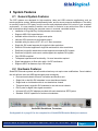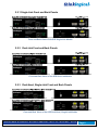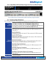
1
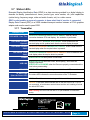
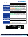
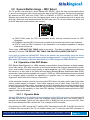
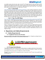
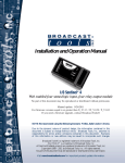
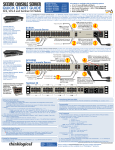
Single-Link and Dual-Link Fiber Optic
Digital Video Extension Systems
Thinklogical, LLC®
100 Washington Street
Milford, Connecticut 06460 U.S.A.
Telephone 1-203-647-8700
Fax 1-203-783-9949
www.thinklogical.com
Copyright Notice
Copyright © 2013. All rights reserved. Printed in the U.S.A.
Thinklogical, LLC®
100 Washington Street
Milford, Connecticut, U.S.A. 06460
Telephone 1-203-647-8700
All trademarks and service marks are property of their respective owners.
Subject: StudioPRO Extender Product Manual
Revision: D, October 2013
StudioPRO Extender Product Manual, Rev. D, October, 2013
Page 1
®
Table of Contents
1. Introduction 3
1.1. Application ....................................................................................................................................................... 3
1.2. Increased Security and Efficiency ................................................................................................................... 3
1.3. Laser Information ............................................................................................................................................. 3
2. System Features .................................................................................................................................................... 5
2.1. General System Features................................................................................................................................ 5
2.2. Hardware Features .......................................................................................................................................... 5
2.2.1. Single-Link DVI Front and Back Panels .................................................................................................... 6
2.2.2. Dual-Link DVI Front and Back Panels ...................................................................................................... 6
2.2.3. Dual-Head, Single-Link DVI Front and Back Panels ................................................................................ 6
2.2.4. Rack-Mount, 3x Dual-Head, Single-Link DVI Front and Back Panels ...................................................... 7
2.3. Technical Specifications .................................................................................................................................. 7
3. Connecting the SPE System ................................................................................................................................. 9
3.1. Contents .......................................................................................................................................................... 9
3.2. Single-Link ....................................................................................................................................................... 9
3.3. Dual-Link.......................................................................................................................................................... 9
3.4. Dual-Head, Single-Link .................................................................................................................................. 10
3.5. Rack-Mount, 3x Dual-Head, Single-Link ....................................................................................................... 10
3.6. Order of Installation Events ........................................................................................................................... 11
3.6.1. Fiber Optic Cables .................................................................................................................................. 11
3.6.2. Digital Video Interface (DVI-D) Input - Transmitter ................................................................................. 11
3.6.3. Digital Video Interface (DVI-D) Output - Reveiver .................................................................................. 11
3.6.4. USB Type B - Transmitter ....................................................................................................................... 11
3.6.5. USB Type A - Receiver ........................................................................................................................... 12
3.6.6. AC to DC Power Supply .......................................................................................................................... 12
3.7. Status LEDs ................................................................................................................................................... 13
3.7.1. Transmitter .............................................................................................................................................. 13
3.7.2. Receiver .................................................................................................................................................. 13
3.8. General Button Usage – DDC Select ............................................................................................................ 14
3.8.1. Operation of the DDC Modes.................................................................................................................. 15
4. Regulatory and Safety Requirements................................................................................................................ 16
4.1. Safety Requirements ..................................................................................................................................... 16
4.1.1. Symbols Found on the Product............................................................................................................... 16
4.1.2. Product Serial Number ............................................................................................................................ 16
4.1.3. Industry-Standard Connections to the Product ....................................................................................... 17
4.2. Regulatory Compliance ................................................................................................................................. 17
4.2.1. North America ......................................................................................................................................... 17
4.2.2. Australia & New Zealand ........................................................................................................................ 17
4.2.3. European Union ...................................................................................................................................... 17
4.2.4. Product Standards Compliance .............................................................................................................. 17
4.3. Supplementary Information ........................................................................................................................... 18
5. How to Contact Us ............................................................................................................................................... 18
5.1. Customer Support ......................................................................................................................................... 18
5.1.1. Website ................................................................................................................................................... 19
5.1.2. Email ....................................................................................................................................................... 19
5.1.3. Telephone ............................................................................................................................................... 19
5.1.4. Fax ........................................................................................................................................................ 20
5.2. Product Support ............................................................................................................................................. 20
5.2.1. Warranty.................................................................................................................................................. 20
5.2.2. Return Merchandise Authorization.......................................................................................................... 20
5.2.3. Our Address ............................................................................................................................................ 20
Appendix A: StudioPRO Extender Models ............................................................................................................ 21
Appendix B: SPE Stand-Alone Enclosure Dimensions ........................................................................................ 22
Appendix C: SPE Quick Start Guides ..................................................................................................................... 23
StudioPRO Extender Product Manual, Rev. D, October, 2013
Page 2
®
Introduction
1.1. Application
Powered by Thinklogical’s® cutting edge, patent-pending MRTS (Multi Rate Transmission
System) Technology, our StudioPRO Extender (SPE) DVI Extension System transports every
frame of a DVI video stream seamlessly with no compression or dropped frames. In addition, all
high speed peripherals function with no latency. Using standard SFP+ transceivers, the system uses
multi-mode or single-mode fiber optic cable to place a digital monitor or projector up to 1000 meters
(3280 feet) away from the controlling computer without loss of resolution. Using single-mode SFP+
modules and fiber optic cable, distances up to 40km are possible. Installation is plug-and-play and
no adjustments are necessary.
Comprised of two compact units, each SPE transmitter connects to the host computer with standard
USB and DVI cables and each receiver provides four USB 2.0 ports for connection of peripheral devices
as well as video connections. External power is required for both the transmitter and receiver units and
two universal AC to 5VDC power supplies are included. In addition, indicator LEDs provide link
performance status at a glance.
The SPE successfully and effectively delivers DVI and USB peripherals when and where you need them.
1.2 Increased Security and Efficiency
The ability to locate the CPU remotely from the monitor and peripherals allows full control of the
computer environment. It is now possible to position the monitor or projector in any setting from office to
lecture hall to boardroom while keeping the computer secure in a controlled location.
1.3 Laser Information
All StudioPRO Extender models are designed and identified as Class 1 LASER products.
StudioPRO Extender Product Manual, Rev. D, October, 2013
Page 3
®
StudioPRO Extender, Single-Link application
StudioPRO Extender Product Manual, Rev. D, October, 2013
Page 4
®
2 System Features
2.1 General System Features
The SPE systems are designed for high-resolution video and USB extension applications such as
remote projection centers, theaters and assembly halls, and for secure computer installations. The ability
to remotely locate the CPU away from the monitor and peripherals allows full control of your computer
environment. It is now possible to position your monitor or projector in any setting from office to lecture
hall to boardroom while keeping the computer secure in a remote, controlled location.
•
•
•
•
•
•
•
•
•
•
•
•
•
Installation is Plug-and-Play: No adjustments are necessary
Supports USB 2.0 hi-speed devices
Available with multi-mode or single-mode optics
Indicator LEDs provide link performance status
Available with your choice of ST, SC or LC fiber connectors
Single-link DVI model supports all single-link video resolutions
Dual-link DVI model supports all single-link and dual-link video resolutions
Dual-head, single-link stand-alone model supports two separate DVI signals.
Dual-head, single-link rack-mount model supports six separate DVI signals.
Fully DDC2B compliant
Transparent operation and functionality - No user interaction required
Signal transmission via fiber optic cable - No RF interference
Supports HDCP at distances up to 300 meters
2.2 Hardware Features
StudioPRO Extender systems are self-contained and may not require user modifications. Once installed,
the unit delivers video and USB signals clearly and consistently.
•
•
•
•
•
•
•
Enclosed metal chassis for each Transmitter and Receiver unit
Single-link or dual-link DVI extenders in one stand-alone chassis
Single-head or dual-head models in one stand-alone chassis
Three dual-head, single-link DVI extenders in one rack-mount chassis
DVI-D ports for digital video signal connection
Universal AC to 5VDC adapters provided with each stand-alone SPE System
Standard 120VAC operation for rack-mount extenders
StudioPRO Rack-Mount Transmitter
See Appendix A on page 21 for the complete list of StudioPRO Extender Model part numbers.
StudioPRO Extender Product Manual, Rev. D, October, 2013
Page 5
®
2.2.1 Single-Link Front and Back Panels
Front and Back Views of the SPE Single-Link Models
2.2.2 Dual-Link Front and Back Panels
Front and Back Views of the SPE Dual-Link Models
2.2.3 Dual-Head, Single-Link Front and Back Panels
Front and Back Views of the SPE Dual-Head, Single-Link Models
StudioPRO Extender Product Manual, Rev. D, October, 2013
Page 6
®
2.2.4 Rack-Mount 3X Dual-Head, Single-Link Front and Back Panels
Front and Back Views of the Rack-Mount SPE 3X Dual-Head, Single-Link Model
2.3 Technical Specifications
Each Thinklogical StudioPRO Extender System® is designed to the following specifications:
USB Type A to USB Type B Cable, 6FT, All models (1)
Electrical DVI-D Male to DVI-D Male Cable, 2M, Stand-Alone, Single Link Tx (1)
Cables DVI-D Male to DVI-D Male Cable, 2M, Rack-Mount, Single-Link Tx (6)
(supplied) DL DVI-D Male to DVI-D Male Dual-Link Cable, 2M, Stand-Alone, Dual Link Tx (1)
DVI-D Male to DVI-D Male Cable, 2M, Dual head, Single-Link Tx (2)
Single-Link Receivers:
DVI-D female video output (2), Fiber connectors (2), USB-A connectors (4), DC
Power jack (1)
Dual-Link Receivers:
Dual-Link DVI-D female video output (2), Fiber connectors (3), USB-A connectors
(4), DC Power jack (1)
Single-Link Transmitters:
DVI-D female video input (1), DVI-D female video output (1), Fiber connectors (2),
USB-B connector (1), DC Power jack (1)
Dual-Link Transmitters:
Standard Dual-Link DVI-D female video input (1), Dual-Link DVI-D female video output (1),
Connectors Fiber connectors (3), USB-B connectors (1), DC Power jack (1)
Dual-Head, Single-Link Receivers:
DVI-D female video output (2), Fiber connectors (3), USB-A connectors (4), DC
Power jack (1)
Dual-Head, Single-Link Transmitters:
DVI-D female video input (2), Fiber connectors (3), USB-B connectors (1), DC
Power jack (1)
Rack-Mount 3X Dual-Head, Single-Link Transmitters:
DVI-D female video input (6), Fiber connectors (9), USB-B connectors (3), AC
Power Input (1)
DDC Protocol Full DDC2B compliant
StudioPRO Extender Product Manual, Rev. D, October, 2013
Page 7
®
Optical Budget
>6 dB multi-mode; >15 dB single-mode 40km optics; >8 dB single-mode
10km optics
Transmitter and Receiver lasers meet Class 1 Laser specifications.
Laser Output
(Class 1 lasers do not require any special precautions under conditions of
Specifications normal use.)
Single-Link:
L1: Data Tx to Rx and Video
L2: Data Rx to Tx
Fiber-Optic Cables
Dual-Link:
L1: Data Tx to Rx and Video (Primary)
L2: Data Rx to Tx
L3: Video (Secondary)
Fiber is either multi-mode, 50 micron or 62.5 micron with ST-, SC- or LCtype connectors or single-mode with LC-type connectors.* (Fiber cable is
either customer-supplied or can be ordered from Thinklogical.)
Fiber Distances
Optical Couplant
Up to 350 meters using type OM2 (5/125µm)
Up to 750 meters using type OM3 enhanced (5/125µm)
Up to 1000 meters using type OM4 (5/125µm)
Up to 40 kilometers using single-mode (9/125µm)
For use with all Single-Mode models only.
A syringe pre-loaded with optical coupling gel is available. The gel is applied
to the connector end face to reduce the difference in the index of refraction
and Fresnel reflections at the interface of the mated connectors.
Operating
Temperature 0 to 50 °C (32 to 122 °F), 5 to 95% RH, non-condens ing
& Humidity
Housing
Dimensions*
Without mounting brackets:
7.875” W x 6.625” D x 1.75” H
(200.02 mm x 168.27 mm x 44.45 mm)
With mounting brackets:
9.00” W x 6.625” D x 1.75” H
(228.60 mm x 168.27 mm x 44.45 mm)
Wall-mount keyhole slot spacing:
8.50” W x 5.75” D
(215.90 mm x 146.05 mm)
Rack-Mount Housing without mounting brackets:
17.47” W x 11.34” D x 1.72” H
(443.64 mm x 287.99 mm x 43.69 mm)
Rack-Mount Housing with mounting brackets:
19.01” W x 11.34” D x 1.72” H
(482.75 mm x 287.99 mm x 43.69 mm)
Input: AC 100-240V @ 50/60Hz 0.55A
Supply Voltage Output: +5.0 VDC @ 4 A
*Also see Appendix B, page 22 for more housing dimensions
StudioPRO Extender Product Manual, Rev. D, October, 2013
Page 8
®
3 Connecting the StudioPRO Extender® System
3.1 Contents
When you receive your Thinklogical StudioPRO Extender System®, you should find the following items:
StudioPRO Extender® Transmitter
StudioPRO Extender® Receiver
For stand-alone units, AC to DC Power Adapter (PWR-000022-R) – (2)
For rack-mount units (Tx only), AC line cord (domestic or international available) (1)
USB Cable, 6 Feet (1 for stand-alone units, 3 for rack-mount units)
DVI-D (M to M) Video Cable, 2 Meters (1 for single-head units, 2 for dual-head units, 6 for rackmount units)
StudioPRO Extender® Product Manual (CD)
•
•
•
•
•
•
•
All physical connections to the product use industry-standard connectors.
3.2 Single-Link
Source CPU
SPE Single-Link Connections
3.3 Dual-Link
Source CPU
SPE Dual-Link Connections
StudioPRO Extender Product Manual, Rev. D, October, 2013
Page 9
®
3.4
Dual-Head, Single-Link
Source CPU
SPE Dual-Head, Single-Link Connections
3.5
Rack-Mount, 3X Dual-Head, Single-Link
StudioPRO 3X DUAL-HEAD, SINGLE-LINK EXTENDER TRANSMITTERS
VEL-SP6MSL-LCTX
DVI 1
DVI 3
DVI 5
DVI 2
DVI 4
DVI 6
USB 2.0
USB 2.0
USB 2.0
Source CPU 1
L1: Video 1 & Data Tx to Rx
L2: Data Rx to Tx
L3: Video 2
Source CPU 2
Source CPU 3
DVI to DISPLAY
1
CPU 1
DVI to DISPLAY
1
CPU 2
DVI to DISPLAY
1
CPU 3
DVI to DISPLAY
2
CPU 1
DVI to DISPLAY
2
CPU 2
DVI to DISPLAY
2
CPU 3
USB Devices
USB Devices
USB Devices
THREE StudioPRO EXTENDER DUAL-HEAD, SINGLE-LINK RECEIVERS
VEL-SP2MSL-LCRX
SPE Rack-Mount, 3X Dual-Head, Single-Link Connections
StudioPRO Extender Product Manual, Rev. D, October, 2013
Page 10
®
3.6 Order of Installation Events
Refer to the SPE Quick Start Guides included in Appendix C on pages 23-26 for detailed installation
instructions.
3.6.1 Fiber Optic Cables
Fiber Optic cables for the SPE system are not included but are available commercially or through
Thinklogical®. Please contact your Thinklogical® sales representative for a quotation on your required
cable length or call us at 1-800-291-3211.
Two to three fiber optic cables must be run between the location of the SPE Transmitter (at the CPU or
other DVI-D video source) and the SPE Receiver (monitor, projector, etc.). The standard multi-mode
fiber cable must be 50 micron, terminated with an LC, SC, or ST-type connector. Single-mode fiber optic
cables with SC-, ST- or LC-type connectors (UPC polish) are available.
Be careful to not kink or pinch the fiber cable as it is being installed and keep all bend radii to no less
than 3 inches. Connect your fiber cables (L1Tx to L1Rx, L2Tx to L2Rx, etc.) to the fiber connectors on
each pair of SPE Transmitters and Receivers and dress the cable to prevent crushing, pinching or other
damage.
Fiber Optic Cable with LC-Type connectors
3.6.2 Digital Video Interface (DVI-D) Input – Transmitter
The SPE Transmitter connects to your DVI video source (DVI-D video card) using the provided DVI-D
male-to-male cable. The Digital Video Interface connector on the transmitter will not accept other
DVI connectors such as DVI-I or DVI-A.
DVI-D (Digital Video Interface) Connector
3.6.3 Digital Video Interface (DVI-D) Output - Receiver
The SPE Receiver unit connects to your DVI-D video monitor, projector, or other viewing device at the
remote destination. Your device must have a DVI-D connector.
3.6.4 USB Type B – Transmitter
Connect your PC’s USB-A port to the Transmitter’s USB-B port using the provided USB A to B Cable
(CBL000015-006FR). The USB-B port is located on the rear panel of the Transmitter unit.
USB Type B port and connector
StudioPRO Extender Product Manual, Rev. D, October, 2013
Page 11
®
3.6.5 USB Type A – Receiver
Using the cables on your USB devices, connect up to four devices to any of the USB- A ports located on
the rear panel of the Receiver unit.
USB Type A connector and port
3.6.6 AC to DC Power Adapter
Two wall-mount AC to 5VDC power adapters (PWR-000022-R) are included. A power jack located on
the rear panel of the transmitter and receiver units accepts the 5VDC input.
5VDC
POWER SUPPLY SPECIFICATIONS
• Output: +5VDC, 4A
• Universal Input: 100-240 VAC 50/60Hz Nominal
• Continuous Short Circuit Protection
• Over Voltage Protection
• Conductive EMI Meets CISPR/FCC Class B high efficiency, 75% Typical
• AC Plug is adaptable (optional international adapters available)
AC to 5VDC Power Supply (PN: PWR-000022-R) with optional AC adapters
StudioPRO Extender Product Manual, Rev. D, October, 2013
Page 12
®
3.7 Status LEDs
Extended Display Identification Data (EDID) is a data structure provided by a digital display to
describe its identity (manufacturer’s name, product type, serial number, etc.) and capabilities
(native timing, frequency range, video and audio formats, etc.) to a video source.
EDID is what enables a personal computer to know what kind of monitor is connected.
Display Data Channel (DDC) is a VESA standard transport medium between a CPU’s graphics
adapter and monitor used to pass EDID.
3.7.1 Transmitter
Indicator LEDs
DDC MODE: Pass-Thru
Status
Local LED is GREEN & Remote LED is GREEN: Acts as a direct
connection between CPU and display. No emulation is performed.
DDC MODE: Remote Local LED is OFF & Remote LED is Green: EDID is read from the
Dynamic remote display and is updated each time the remote display changes.
DDC MODE: Remote Local LED is ORANGE & Remote LED is Green: EDID is read from the
Static remote display when the acquire button is pressed.
DDC MODE: Local Local LED is GREEN & Remote LED is ORANGE: EDID is read from the
Static local display when the acquire button is pressed.
POWER GREEN LED is ON when power is connected.
GREEN LED is ON when the Power, device port(s), and Fibers are
properly connected.
USB LINK
GREEN LED is BLINKING when the fibers are properly connected and the
Host is busy enumerating.
USB HOST GREEN LED is ON when the computer establishes a USB connection.
TX Status LED
The status LED indicates the connection status of the TX Extender.
(Near the Power LED)
GREEN: Fiber L2 is connected and a good link is established
ORANGE: Local Static Mode selected and no fiber link from RX to TX (L2 is
not connected), or both buttons are held down and the unit is waiting to reload
the default DDC table.
RED Flashing: No Fiber Link from RX to TX (Not available in Local Static
mode).
StudioPRO Extender Product Manual, Rev. D, October, 2013
Page 13
®
3.7.2
Receiver
Indicator LEDs
Status
DDC MODE: Pass-Thru
Local LED is GREEN & Remote LED is GREEN: Acts as a direct
connection between CPU and display. No emulation is performed.
DDC MODE: Remote Local LED is OFF & Remote LED is Green: EDID is read from the
Dynamic remote display and is updated each time the remote display changes.
DDC MODE: Remote Static
DDC MODE: Local Static
Local LED is ORANGE & Remote LED is Green: EDID is read from
the remote display when the acquire button is pressed.
Local LED is GREEN & Remote LED is ORANGE: EDID is read from
the local display when the acquire button is pressed.
POWER GREEN LED is ON when power is connected.
Shows the status of connections:
GREEN LED is ON when the Power, device port(s), and Fibers are
LINK properly connected.
GREEN LED is BLINKING when the fibers are properly connected and
while the Host is enumerating.
HOST GREEN LED is ON when the computer establishes a USB connection.
1, 2, 3, 4
GREEN LED is ON: Indicates an established connection to USB-A
Port 1, 2, 3 and/or 4.
RX Status LED
The status LED indicates the connection status of the RX Extender.
(Near the Power LED)
GREEN: Good Link and DVI monitor connected to primary port (port on left
looking at DVI connectors).
ORANGE: No DVI monitor connected to primary port.
RED Flashing: No Fiber Link from TX to RX (L1 is not connected).
StudioPRO Extender Product Manual, Rev. D, October, 2013
Page 14
®
3.8 General Button Usage – DDC Select
The TX and RX units both have a button labeled DDC SELECT. When the data communications fibers
L1 and L2 are connected, either unit will control the state of the DDC operation. Each press of the button
will advance the DDC state from PASS THRU to DYNAMIC to STATIC and back to PASS THRU.
(Because the buttons are small, a firm, fine-tipped device such as a mechanical pencil tip or stylus may
work best). When the units are disconnected, the DDC state of the TX unit is the master and will be sent
to the RX when data communications are restored.
• In PASS THRU mode, the CPU communicates directly with the connected monitor for DDC
information.
• In DYNAMIC mode the DDC of the monitor is read from the receiver and stored in the transmitter.
• In STATIC mode the DDC information in the transmitter is not changed regardless of changes
made at the receiver end.
There is also a DEFAULT DDC TABLE stored in the device. This table is suitable for use with many
standard PC monitors. THE DEFAULT DDC TABLE CAN ONLY BE LOADED FROM THE TX.
If you wish to restore the Default DDC Table to the product and automatically place the device
into STATIC DDC mode, hold both buttons down for approximately 7 seconds or until you see the
DDC mode LEDs change to Remote Static Mode (LCL LED=Orange and REM LED=Green).
3.8.1 Operation of the DDC Modes
DDC (Display Data Channel) is a VESA standard communications channel between a display adapter
and a video monitor. DDC data is stored in a monitor and describes the monitors characteristics (vendor
name, serial number, frequency range, analog or digital capabilities, etc.). DDC information is read from
the monitor by a video card so the video card can gather Extended Display Identification Data (EDID)
and provide a video format acceptable to the monitor. (EDID is a VESA standard data structure provided
by a computer display to describe its capabilities to a graphics card. It is what enables a personal
computer to detect what kind of monitor is connected.)
As the transmitter emulates a monitor it must provide a DDC table to the video card in order for the video
card to provide images for transport. Some video cards may turn off video output if the DDC is not
present at boot up (missing monitor, hot-plugged or the DDC information does not match expected digital
or analog parameters). Some video cards are more tolerant and will produce video output under many
conditions. Due to the variability of video card DDC handling, Thinklogical products provide the DDC
support modes detailed below.
3.8.1.1 Dynamic Mode
Dynamic DDC mode is the default and recommended mode of DDC operation. In this mode the RX
will read the DDC from a monitor under two conditions; during power-up and if the monitor cable is
removed and reinstalled. The RX will only read the DDC to RAM (It will not be stored on the RX). Once
the RX has validated the DDC it informs the TX of a change in DDC information.
Once informed of a DDC change the TX reads the DDC information from the RX. If the DDC from the RX
is different from that stored in the TX non-volatile memory, the TX writes the new DDC information to
StudioPRO Extender Product Manual, Rev. D, October, 2013
Page 15
®
non-volatile memory that the video card can read. The TX then informs the video card that the DDC
information has changed so that the video card can read the DDC and act accordingly. In this mode the
CPU may be booted up with the TX turned off or disconnected from the RX since the TX non-volatile
DDC memory can be read by the video card without TX power.
3.8.1.2 Static Mode
Static DDC mode is typically used in switching situations. In some switching situations the customer
may be using multiple monitors that are all capable of handling the same video resolution but some of
the monitors in the system may cause the video card to turn off the video output. Another possible use of
Static DDC mode is when a video card does not recover from a video cable being hot-plugged while the
system is booted. Static mode resolves these issues by preventing the TX from writing to the non-volatile
DDC memory stored on the TX and static mode prevents the TX from informing the video card of a
change in DDC data. In this mode the CPU may be booted up with the TX off or disconnected from the
RX since the TX non-volatile DDC memory can be read by the video card without TX power.
3.8.1.3 Pass Thru DDC Mode
Pass Thru DDC mode gives the video card direct access to the monitor connected to the RX. This
mode is useful in HDCP (High-bandwidth Digital Content Protection) applications. In Pass Thru DDC
mode the video card can directly write-to and read-from the monitor. The video card will be informed of
the presence or absence of a connected monitor. In this mode there must be a valid data communication
path between the CPU and a connected monitor before the CPU can be booted.
When a Thinklogical product is supplied to customers it typically comes with a default table that provides
a maximum resolution of 1920x1200. If the customer elects to use the default DDC data in static mode,
the video card will read that the TX (emulating a monitor) is capable of showing 1920x1200. If the
monitor connected at the RX cannot display a resolution as high as 1920x1200 the monitor will not
display an image.
4 Regulatory and Safety Requirements
4.1 Safety Requirements
4.1.1 Symbols Found on the Product
Markings and labels on the product follow industry-standard conventions. Regulatory markings found on
the products comply with domestic and international requirements.
.
4.1.2 Product Serial Number
Thinklogical® products have a unique serial number printed on an adhesive label that is fixed, typically,
to the underside of the unit. The serial number includes a date-code formatted as 2 digits for the week
and 2 digits for the year, plus two to four digits for a unique unit number.
Example: Serial number 2813124 indicates that the unit was built in the 28th week of the year 2013 and
is unit number 124.
StudioPRO Extender Product Manual, Rev. D, October, 2013
Page 16
®
4.1.3 Industry-Standard Connections to the Product
Connections and installation hardware for the product use industry-standard devices and methods. All
wiring connections to the customer equipment minimize proprietary or customized connectors and
cabling. Power connections are made with regionally appropriate power cords and approved methods.
4.2 Regulatory Compliance
Thinklogical® SPE products are designed and made in the U.S.A. SPE products have been tested by a
nationally certified testing laboratory and found to be compliant with the following standards (both
domestic USA and international locations).
4.2.1 North America
These products comply with the following standards:
Safety
• UL60950: 2000
• CAN/CSA C22.2 No. 60950-00
LASER Safety
• CDRH 21CFR 1040.10
• Class 1 LASER Product
Electromagnetic Interference
• FCC CFR47, Part 15, Class A
• Industry Canada ICES-003 Issue 2, Revision 1
4.2.2 Australia & New Zealand
This is a Class A product. In a domestic environment this product may cause radio interference, in which
case the user may be required to take adequate measures.
4.2.3 European Union
4.2.3.1
Declaration of Conformity
Manufacturer’s Name & Address:
Thinklogical, LLC®
100 Washington Street
Milford, Connecticut 06460 USA
Telephone 1-203-647-8700
Product Name: StudioPRO USB 2.0 and DVI Extender
These products comply with the requirements of the Low Voltage Directive 72/23/EEC and the EMC
Directive 89/336/EEC.
4.2.4 Product Standards Compliance
Safety
• IEC60950:1992+A1, A2, A3, A4, A11
LASER Safety
• IEC60825-1/2
• Class 1 LASER Product
Electromagnetic Emissions
• EN55022: 1994 (IEC/CSPIR22: 1993)
• EN61000-3-2/A14: 2000
• EN61000-3-3: 1994
StudioPRO Extender Product Manual, Rev. D, October, 2013
Page 17
®
Electromagnetic Immunity
• EN55024: 1998 Information Technology Equipment-Immunity Characteristics
• EN61000-4-2: 1995 Electro-Static Discharge Test
• EN61000-4-3: 1996 Radiated Immunity Field Test
• EN61000-4-4: 1995 Electrical Fast Transient Test
• EN61000-4-5: 1995 Power Supply Surge Test
• EN61000-4-6: 1996 Conducted Immunity Test
• EN61000-4-8: 1993 Magnetic Field Test
• EN61000-4-11: 1994 Voltage Dips & Interrupts Test
4.3 Supplementary Information
The following statements may be appropriate for certain geographical regions and might not apply to
your location.
__________________________________________________________________________________
NOTE: This equipment has been tested and found to comply with the limits for a Class A
digital device, pursuant to part 15 of the FCC Rules. These limits are designed to provide
reasonable protection against harmful interference when the equipment is operated in a
commercial environment. This equipment uses, generates and can radiate radio frequency
energy and, if not installed and used in accordance with the instruction manual, may cause
harmful interference to radio communications. Operation of this equipment in a residential area
may cause harmful interference in which case the user may be required to take corrective
measures.
__________________________________________________________________________________
NOTE: This Class A digital apparatus complies with Canadian ICES-003 and has been
verified as compliant within the Class A limits of the FCC Radio Frequency Device Rules (FCC
Title 47, Part 15, Subpart B CLASS A), measured to CISPR 22: 1993 limits and methods of
measurement of Radio Disturbance Characteristics of Information Technology Equipment.
__________________________________________________________________________________
NOTE: This Class A digital apparatus meets all requirements of the Canadian InterferenceCausing Equipment Regulations.
Cet appareil numérique de la classe A respecte toutes les exigencies du Règlement sur le
matérial brouilleur du Canada.
__________________________________________________________________________________
WARNING: This is a Class A product. In a domestic environment this product may cause
radio interference, in which case the user may be required to take corrective measures.
5 How to Contact Us
5.1 Customer Support
Thinklogical® is an engineering company and you will receive the assistance you require directly from
our most knowledgeable engineers. We believe that the first line of support is the design engineer that
developed each particular product. Therefore your needs will be handled promptly by our in-house
engineers who are most familiar with your products.
StudioPRO Extender Product Manual, Rev. D, October, 2013
Page 18
®
5.1.1 Website
Visit our website for more product information, current updates and the complete line of Thinklogical®
products.
Our internet website offers product information on all current systems, including technical specification
sheets, Quick Start Guides, product diagrams and more. We are continually updating our website, so be
sure to refresh your browser when visiting our website to see the most up-to-date information.
Internet: www.thinklogical.com
__________________________________________________________________________________
NOTE: Most online documents are stored as Adobe Acrobat “PDF” files. If you do not
have the Adobe Acrobat reader needed to view PDF files, visit www.adobe.com for a download.
__________________________________________________________________________________
5.1.2 Email
Thinklogical® is staffed Monday through Friday from 8:30am to 5:30pm, Eastern Time Zone. We will do
our best to respond to your email inquiries promptly. Please use the following email addresses according
to your needs:
[email protected] – Information about Thinklogical® and our products.
[email protected] – Sales Department - orders, questions or issues.
[email protected] – Product support, technical issues or questions, product repairs and
request for Return Merchandise Authorization.
5.1.3 Telephone
Telephone Sales: Contact our expert sales staff via telephone in Milford, Connecticut at 1-203-6478700 or, if in the continental US, you may use our toll-free number 1-800-291-3211. We are here
Monday through Friday from 8:30am to 5:30pm, Eastern Time Zone. Ask for your sales representative’s
direct dial phone number when you call.
Telephone Product Support: Contact Product Support via telephone in Milford, CT at 1-203-647-8700.
The support lines are manned Monday through Friday, 8:30am to 5:30pm, Eastern Time Zone.
International Sales: Please contact our US sales staff in Milford, CT at 1-203-647-8700. We are here
Monday through Friday, 8:30am to 5:30pm, Eastern Time Zone (same as New York City). If leaving a
voice message, please provide a preferred time for us to call back so we can reach you at your
convenience.
Our switchboard attendant will direct your call during regular business hours. We have an automated
attendant answering our main telephone switchboard after regular business hours and on holidays. You
can leave a voice message for an individual at any time. Our Sales Representatives have direct numbers
to facilitate your calls to us.
StudioPRO Extender Product Manual, Rev. D, October, 2013
Page 19
®
5.1.4 Fax
Our company facsimile number is 1-203-783-9949. Please indicate the nature of the fax on your cover
sheet and provide return contact information.
5.2 Product Support
Thinklogical’s® support personnel are available Monday through Friday from 8:30am to 5:30pm, Eastern
Time Zone. If your application might require assistance at some time outside of our normal business
hours, please contact us beforehand and we will do our best to make arrangements to help you with your
Thinklogical® products.
5.2.1 Warranty
Thinklogical® products carry a one year warranty, with longer terms available at the time of purchase on
most products. Please refer to your product invoice for your product’s Warranty Terms & Conditions.
5.2.2 Return Merchandise Authorization
Return Merchandise Authorization must include contact information (phone preferred) in the event we
need to contact you.
After receiving your RMA number, please ship the unit postpaid, in the original container if possible, with
the RMA# prominently displayed on the shipping container. We will contact you about your product once
we determine its status.
Products received without Return Merchandise Authorization and/or contact information may delay
service or support.
5.2.3 Our Address
If you have any issues with your product, have product questions or need technical assistance, please
call us at 1-203-647-8700 and let us help.
If shipping something with an RMA # or if you’d like to write us, we are located at:
Thinklogical, LLC®
100 Washington Street
Milford, CT 06460 USA
StudioPRO Extender Product Manual, Rev. D, October, 2013
Page 20
®
Appendix A: StudioPRO Extender® Models
All models listed are available from Thinklogical®:
Part Number
Model
DUAL-LINK, MULTI-MODE
VEL-SP0MDL-LCRX
VEL-SP0MDL-LCTX
VEL-SP0MDL-SCRX
VEL-SP0MDL-SCTX
VEL-SP0MDL-STRX
VEL-SP0MDL-STTX
STUDIOPRO EXTENDER, DUAL LINK, 2.0, MULTIMODE, RX, LC
STUDIOPRO EXTENDER, DUAL LINK, 2.0, MULTIMODE, TX, LC
STUDIOPRO EXTENDER, DUAL LINK, 2.0, MULTIMODE, RX, SC
STUDIOPRO EXTENDER, DUAL LINK, 2.0, MULTIMODE, TX, SC
STUDIOPRO EXTENDER, DUAL LINK, 2.0, MULTIMODE, RX, ST
STUDIOPRO EXTENDER, DUAL LINK, 2.0, MULTIMODE, TX, ST
SINGLE-LINK, MULTI-MODE
VEL-SP0MSL-LCRX
STUDIOPRO EXTENDER, SINGLE LINK, 2.0, MULTIMODE, RX, LC
VEL-SP0MSL-LCTX
STUDIOPRO EXTENDER, SINGLE LINK, 2.0, MULTIMODE, TX, LC
VEL-SP0MSL-SCRX
STUDIOPRO EXTENDER, SINGLE LINK, 2.0, MULTIMODE, RX, SC
VEL-SP0MSL-SCTX
STUDIOPRO EXTENDER, SINGLE LINK, 2.0, MULTIMODE, TX, SC
VEL-SP0MSL-STRX
STUDIOPRO EXTENDER, SINGLE LINK, 2.0, MULTIMODE, RX, ST
VEL-SP0MSL-STTX
STUDIOPRO EXTENDER, SINGLE LINK, 2.0, MULTIMODE, TX, ST
DUAL-LINK, SINGLE-MODE
VEL-SP0SDL-LCRX
STUDIOPRO EXTENDER, DUAL LINK, 2.0, SINGLE MODE, RX, C/UPC
VEL-SP0SDL-LCTX
STUDIOPRO EXTENDER, DUAL LINK, 2.0, SINGLE MODE, TX, LC/UPC
VEL-SP0SDL-SCRX
STUDIOPRO EXTENDER, DUAL LINK, 2.0, SINGLE MODE, RX, SC/UPC
VEL-SP0SDL-SCTX
STUDIOPRO EXTENDER, DUAL LINK, 2.0, SINGLE MODE, TX, SC/UPC
SINGLE-LINK, SINGLE-MODE
VEL-SP0SSL-LCRX
STUDIOPRO EXTENDER, SINGLE LINK, 2.0, SINGLE MODE, RX, LC
VEL-SP0SSL-LCTX
STUDIOPRO EXTENDER, SINGLE LINK, 2.0, SINGLE MODE, TX, LC
VEL-SP0SSL-SCRX
STUDIOPRO EXTENDER, SINGLE LINK, 2.0, SINGLE MODE, RX, SC/UPC
VEL-SP0SSL-SCTX
STUDIOPRO EXTENDER, SINGLE LINK, 2.0, SINGLE MODE, TX, SC/UPC
DUAL-HEAD, SINGLE-LINK, MULTI-MODE
VEL-SP2MSL-LCRX
STUDIOPRO EXTENDER, DUAL HEAD, SINGLE LINK, 2.0, MULTIMODE, RX, LC
VEL-SP2MSL-LCTX
STUDIOPRO EXTENDER, DUAL HEAD, SINGLE LINK, 2.0, MULTIMODE, TX, LC
VEL-SP2SSL-LCRX
STUDIOPRO EXTENDER, DUAL HEAD, SINGLE LINK, 2.0, SINGLEMODE, RX, LC
VEL-SP2SSL-LCTX
STUDIOPRO EXTENDER, DUAL HEAD, SINGLE LINK, 2.0, SINGLEMODE, TX, LC
RACK-MOUNT, 3x DUAL-HEAD, SINGLE-LINK, MULTI-MODE
VEL-SP6MSL-LCTX
STUDIOPRO EXTENDER, 3 DUAL HEAD SINGLE LINK, 2.0, MULTIMODE, TX, LC
SINGLE-LINK, MULTI-MODE, REDUNDANT
VEL-SPRMSL-LCTX
STUDIOPRO EXTENDER, SINGLE LINK, 2.0, REDUNDANT OPTICS, MULTIMODE, TX, LC
StudioPRO Extender Product Manual, Rev. D, October, 2013
Page 21
®
Appendix B: SPE Stand-Alone Enclosure Dimensions
6.625"
(168.27mm)
1.75"
(44.45mm)
5.75"
(146.05mm)
.875"
(22.2mm)
7.875"
(200.02mm)
8.50"
(215.90mm)
9.00"
(228.60mm)
.5625"
(14.29mm)
SPE Chassis Dimensions
NOTE: Drawing is not to scale.
StudioPRO Extender Product Manual, Rev. D, October, 2013
Page 22
StudioPRO
Extender
Single-Link DVI, USB 2.0 Video Extension System
STEP 5: Connect the supplied +5V power
supply (PWR-000022-R) to the transmitter
and plug it into a standard AC source.
QUICK START GUIDE
5
STEP 7: Connect the USB and DVI
StudioPRO SINGLE-LINK EXTENDER TRANSMITTER
7
Acquire Button
Used to initiate DDC collection. Works with all modes except Pass-Thru. Must
be pressed after switching between DDC modes.
Select Button
Used to select the DDC mode. The modes will cycle through Remote
Dynamic, Remote Static, Pass-Thru and Local Static.
Both Buttons held 5 seconds
Holding both buttons for 5 seconds will reload the default DDC table into the
Tx and switch to Remote Static mode.
cables from CPU to transmitter. Turn the
CPU ON. Ensure all system functions are
operating properly.
DVI FROM CPU
STEP 1: Connect the
DVI Local
Display
CPU
6
STEP 6: Connect an optional
STEP 4: Connect the output display
device(s) to the receiver’s DVI TO
DISPLAY ports. The DDC port is the
PRIMARY port and should be used when
there is only one display device connected.
DVI to
Display
1
local monitor to the transmitter’s
DVI LOCAL DISPLAY port.
Connect:
L1 to L1: Data Tx to Rx & DVI
L2 to L2: Data Rx to Tx
4
DVI to Display
(DDC)
2
StudioPRO SINGLE-LINK EXTENDER RECEIVER
STEP 3: Install up to four USB peripheral devices to
STEP 2: Connect the supplied +5V power
the receiver’s USB 2.0 ports.
supply (PWR-000022-R) to the receiver
and plug it into a standard AC source.
Value Your Content
Page 23
Trust Our Proven Ingenuity
multi-mode fiber-optic
cables between the
transmitter and receiver
units (up to 1000 meters).
Appendix C: SPE Quick Start Guides
StudioPRO Extender Single-Link DVI, USB 2.0 Quick Start Guide
StudioPRO Extender Product Manual, Rev. D, October, 2013
CONTENTS:
StudioPRO Single-link Extender Transmitter [1]
StudioPRO Single-link Extender Receiver [1]
USB A-B cable, 6' (CBL-000015-006FR) [1]
DVI-D (M to M) cable, 2M (CBL-000009-002MR) [1]
Universal Power Supply (PWR-000022-R) [2]
StudioPRO Extender Product Manual
USB Devices
3
StudioPRO_Extender_Single-Link_QSG_Manual_Rev_B
®
®
StudioPRO Extender Dual-Link DVI, USB 2.0 Quick Start Guide
StudioPRO Extender Product Manual, Rev. D, October, 2013
Page 24
Page 25
StudioPRO Extender Dual-Head, Single-Link DVI, USB 2.0 Quick Start Guide
StudioPRO Extender Product Manual, Rev. D, October, 2013
CONTENTS:
StudioPRO Dual-Head Extender Transmitter [1]
StudioPRO Dual-Head Extender Receiver [1]
USB A-B cable, 6' (CBL-000015-006FR) [1]
DVI-D Cable (M to M), 2M (CBL-000023-002MR) [2]
Universal Power Supply (PWR-000022-R) [2]
StudioPRO Extender Product Manual
StudioPRO Extender
STEP 5: Connect the supplied +5V power
Dual-Head, Single-Link DVI, USB 2.0 Extension System
supply (PWR-000022-R) to the transmitter
and plug it into a standard AC source.
QUICK START GUIDE
5
USB 2.0
StudioPRO EXTENDER DUAL-HEAD, SINGLE-LINK TRANSMITTER
Acquire Button
Used to initiate DDC collection. Works with all modes except Pass-Thru. Must
be pressed after switching between DDC modes.
Select Button
Used to select the DDC mode. The modes will cycle through Remote
Dynamic, Remote Static, Pass-Thru and Local Static.
Both Buttons held 5 seconds
Holding both buttons for 5 seconds will reload the default DDC table into the
Tx and switch to Remote Static mode.
STEP 6: Connect the USB, DVI 1 and DVI 2 cables
from the CPU to the transmitter. Turn the CPU ON.
Ensure all system functions are operating properly.
6
DVI FROM CPU 2
1
DVI FROM CPU 1
STEP 1: Connect the multiCPU
DVI to Display 2
STEP 4: Connect the output display
4
device(s) to the receiver’s DVI TO
DISPLAY 1 and DVI TO DISPLAY 2 ports.
DVI to Display 1
mode fiber-optic cables
between the transmitter and
receiver units (up to 1000
meters).
Connect:
L1 to L1: Data Tx to Rx & DVI 1
L2 to L2: Data Rx to Tx
L3 to L3: DVI 2
2
StudioPRO EXTENDER DUAL-HEAD, SINGLE-LINK RECEIVER
STEP 2: Connect the supplied +5V power
STEP 3: Install up to four USB peripheral
devices to the receiver’s USB 2.0 ports.
Ensure the devices are turned on.
3
supply (PWR-000022-R) to the receiver
and plug it into a standard AC source.
USB Devices
StudioPRO_Extender_Dual-Head_Single-Link_QSG_Manual
®
®
Rack-Mount StudioPRO Extender, 3X Dual-Head, Single-Link DVI, USB 2.0 Quick Start Guide
StudioPRO Extender Product Manual, Rev. D, October, 2013
Page 26