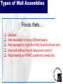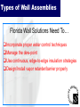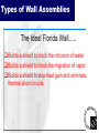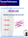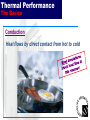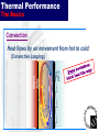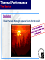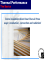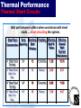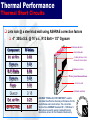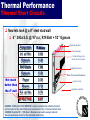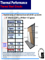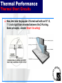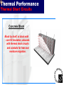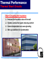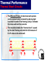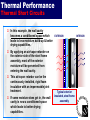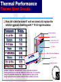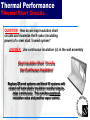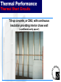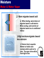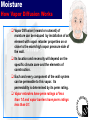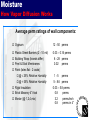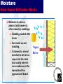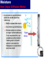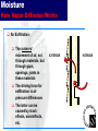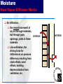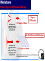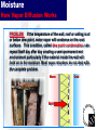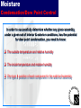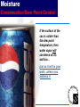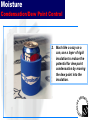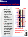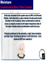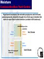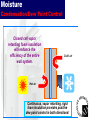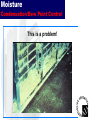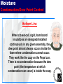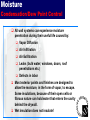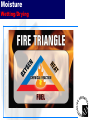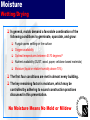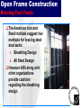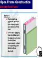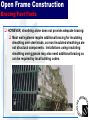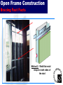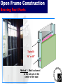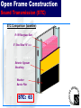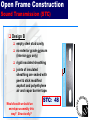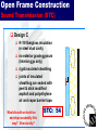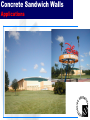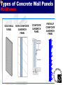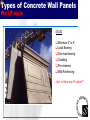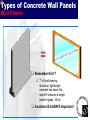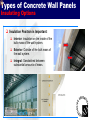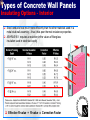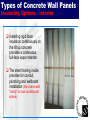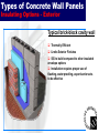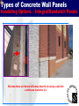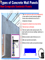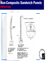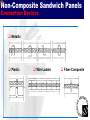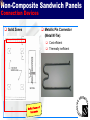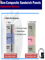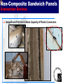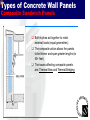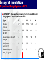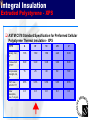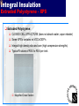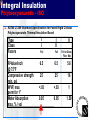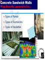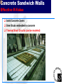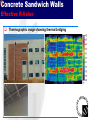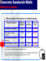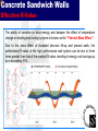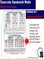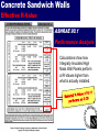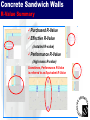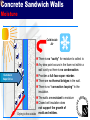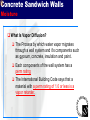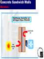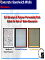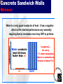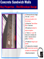
1
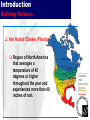
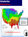
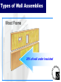
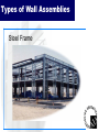
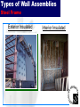
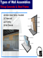
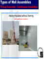
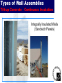
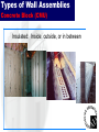
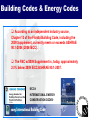
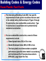
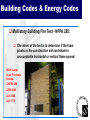
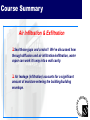
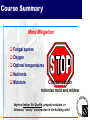
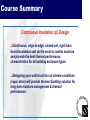
FEFPA Winter Conference Amelia Island, FL January 21, 2010 Constructing Walls in Florida; Moisture & Thermal Management Using Rigid Insulation Presented by: Bob Bertig Fuhsco, Inc. Learning Objectives Understand how moisture accumulates in various types of building envelope assemblies. Identify the design and installation challenges, including heat, air and moisture migration, associated with building envelope assemblies and using the ASHRAE requirements of continuous insulation to solve these problems. Evaluate and specify methods that reduce moisture and condensation build-up in Florida walls. Realize the benefits of monolithic/edge-to-edge, continuous insulation on all wall construction types, particularly those containing steel framing of any kind. Learn the techniques to evaluate/specify/install building envelopes that minimize moisture issues and enhance energy efficiency. Course Agenda Introduction Types of Wall Assemblies Thermal Performance - Thermal Short Circuits Moisture in Wall Assemblies - The science behind wall assemblies... How Vapor Diffusion Works... The effects of Air Infiltration/Exfiltration Condensation/ Dew Point Control Wetting/Drying – Mold! Open Frame Construction Frame Wall – Open Framing Bracing Requirements Frame Wall - Sound Transmission Properties Concrete Sandwich Walls Sustainability/”GREEN” Building Codes & Energy Codes Summary Introduction Challenges to Florida Construction Building Envelope/Shell Design and Construction Must Address: Energy Efficiency R-Value Air Infiltration Moisture Control Vapor Drive Bulk Water Mold Introduction Challenges to Florida Construction Questions facing our industry every day: How do we “hurricane harden” our building envelopes? How do we build a functional, cost effective, green and sustainable building envelope? Introduction Building Science Key issues with trying to insulate walls/roofs today: Thermal Bridging (short circuits) Factors limiting the use of cavity insulation Wood or steel framing Plumbing Heating and cooling ductwork Electrical wiring, outlets and junctions Wall cavity convection currents Dew point condensation H-A-M (Heat, Air Infiltration, Moisture Migration) Introduction Building Science Hot Humid Climate (Florida) Region of North America that averages a temperature of 45 degrees or higher throughout the year and experiences more than 40 inches of rain. SEVERE COLD COLD MIXED HUMID HOT DRY HOT HUMID Introduction Building Science All of Florida falls within Climate Zones 1 & 2 Course Agenda Introduction Types of Wall Assemblies Thermal Performance - Thermal Short Circuits Moisture in Wall Assemblies - The science behind wall assemblies... How Vapor Diffusion Works... The effects of Air Infiltration/Exfiltration Condensation/ Dew Point Control Wetting/Drying – Mold! Open Frame Construction Frame Wall – Open Framing Bracing Requirements Frame Wall - Sound Transmission Properties Concrete Sandwich Walls Sustainability/”GREEN” Building Codes & Energy Codes Summary Types of Wall Assemblies Florida Walls Construction Types Wood Framing (Type V construction) Steel Framing Tilt-up, precast, poured-in-place concrete Concrete Block (single-story/multi-story) Types of Wall Assemblies Wood Frame 25% of wall under insulated Types of Wall Assemblies Steel Frame Types of Wall Assemblies Steel Frame Exterior Insulated Interior Insulated Types of Wall Assemblies Tilt-up Concrete & Steel Frame Interior steel frame - insulated Chase wall Z-Furring Hat Channel Types of Wall Assemblies Tilt-up Concrete - Continuous Insulation Interior insulated without framing (continuous foam insulation) Types of Wall Assemblies Tilt-up Concrete - Continuous Insulation Integrally Insulated Walls (Sandwich Panels) Types of Wall Assemblies Concrete Block (CMU) Insulated: Inside, outside, or in between Types of Wall Assemblies Florida Walls… Get wet Are insulated in many different ways Are exposed to high humidity & wind-driven rain Are built without much dew point control Rely heavily on HVAC systems to keep dry Types of Wall Assemblies Florida Wall Solutions Need To… Incorporate proper water control techniques Manage the dew-point Use continuous, edge-to-edge insulation strategies Design/Install vapor retarder/barrier properly Types of Wall Assemblies The Ideal Florida Wall….. Builds a shield to block the intrusion of water Builds a shield to block the migration of vapor Builds a shield to stop heat gain and eliminate thermal short circuits Course Agenda Introduction Types of Wall Assemblies Thermal Performance - Thermal Short Circuits Moisture in Wall Assemblies - The science behind wall assemblies... How Vapor Diffusion Works... The effects of Air Infiltration/Exfiltration Condensation/ Dew Point Control Wetting/Drying – Mold! Open Frame Construction Frame Wall – Open Framing Bracing Requirements Frame Wall - Sound Transmission Properties Concrete Sandwich Walls Sustainability/”GREEN” Building Codes & Energy Codes Summary Thermal Performance The Basics HOW HEAT FLOWS Heat flows three ways from hot to cold: Conduction Convection Radiation Thermal Performance The Basics Conduction Heat flows by direct contact from hot to cold Thermal Performance The Basics Convection Heat flows by air movement from hot to cold: Cold Side Warm Side (Convective Looping ) Thermal Performance The Basics Convection Heat flows by air movement from hot to cold: (Convective Looping ) Hot air balloons float up because warm air rises… Thermal Performance The Basics Radiation Heat travels through space from hot to cold Thermal Performance The Basics Some insulations block heat flow all three ways: conduction, convection and radiation! Thermal Performance The Basics QUESTION: How do we stop heat from flowing into, out of, places where we don’t want it to? ANSWER: Insulate! FACT: Insulation provides resistance to heat flow R-Value is a measure of a material’s ability to resist heat flow…higher R-Value, more resistance to heat flow…better insulating power. Thermal Performance R-Value = 7” of load-bearing structural, light-weight concrete has approximately the same R-Value as a single panel of glass… R-1.4 ! Thermal Performance R-Value Steel is a thermal short circuit; in fact, a ½ inch of R3 rigid board insulation has the same thermal resistance to heat flow as 10 FEET of steel! Thermal Performance R-Value 7.0 6.0 5.0 R /Inch 4.0 3.0 2.0 1.0 0.0 Steel Concrete Gypsum Fiberglass 1/2# PU Bd. Foam EPS 1# Foam XPS 2# PU Foam Foil-faced Iso Thermal Performance R-Value Thermal Short Circuits are designed into wall assemblies leading to a phenomenon called thermal bridging ASHRAE 90.1 recognizes this and applies a correction factor to account for the higher heat loss through the highly conductive steel studs Steel stud walls can be the external shell of the building or an interior chase wall or even provide “furring” for tiltup/concrete block bldg. envelopes Thermal Performance Thermal Short Circuits Effective R-value = R-value x Correction Factor 2 Recent analysis of tested assemblies indicates an R-value of 7.1 for R-19 insulation in normal 6” framing at 16” on center, though the correction factor published in Standard 90.1 currently offers higher credit. Thermal Performance Thermal Short Circuits Batt performance suffers when used alone with steel studs…. short circuiting the system. Steel Stud Construction Stud Spacing Nominal Batt R-Value Cladding Effective Batt RValue Effective Overall Wall Thermal Resistance 4” Steel Stud Tilt Wall, 24” 13 Concrete 7.20 10.16 4” Steel Stud Wall, Ext. Gyp. 16” 13 Stucco 6.00 8.07 6” Steel Stud Tilt Wall 24” 19 Concrete 8.60 11.56 6” Steel Stud Wall, Ext. Gyp. 16” 19 Stucco 7.60 9.67 Thermal Performance Thermal Short Circuits Lets look @ a steel stud wall using ASHRAE correction factors 4” 20Ga S.S. @ 16”o.c., R13 Batt + 1/2” Gypsum Component Int. air film INTERIOR AIR FILM R-Value 0.68 GYPSUM BOARD 4” STEEL STUD @ 16”OC R-13 BATT INSULATION Gypsum 0.45 R-13 Batts 6.00 Gypsum 0.45 Paper 0.06 Stucco 0.18 Ext. air film 0.25 EFFECTIVE: 8.07 EXTERIOR GYPSUM Water protection membrane STUCCO/LATH EXTERIOR AIR FILM ASHRAE “PARALLEL PATH METHOD” used to calculate the effective thermal performance for the metal frame wall construction. The correction factors from ASHRAE Standard 90.1, 1989 User’s Manual were used to assign reduced thermal resistance values for the insulated stud cavity. Thermal Performance Thermal Short Circuits Now lets look @ a 6” steel stud wall 6” 20Ga S.S. @ 16”o.c., R19 Batt + 1/2” Gypsum Component R-Value INTERIOR AIR FILM GYPSUM BOARD Int. air film 0.68 Gypsum 0.45 R-19 Batts 7.60 Gypsum 0.45 Not much Paper 0.06 better than Stucco 0.18 the 4” wall Ext. air film 0.25 EFFECTIVE: 9.67 ASHRAE “PARALLEL PATH METHOD” used to calculate the effective thermal performance for the metal frame wall construction. The correction factors from ASHRAE Standard 90.1, 1989 User’s Manual were used to assign reduced thermal resistance values for the insulated stud cavity. 6” STEEL STUD @ 16”OC R-19 BATT INSULATION EXTERIOR GYPSUM Water Protection Membrane STUCCO/LATH EXTERIOR AIR FILM Thermal Performance Thermal Short Circuits Now lets look @ a 6” steel stud chase wall with tilt- up concrete 6” 20Ga S.S. @ 24”o.c., R19 Batt + 1/2” gypsum similar results Component R-Value Int. air film 0.68 Gypsum 0.45 R-19 Batts 8.60 Concrete 7 inches 1.4 Finish 0.18 Ext. air film 0.25 EFFECTIVE: 11.56 ASHRAE “PARALLEL PATH METHOD” used to calculate the effective thermal performance for the metal frame wall construction. The correction factors from ASHRAE Standard 90.1, 1989 User’s Manual were used to assign reduced thermal resistance values for the insulated stud cavity. Thermal Performance Thermal Short Circuits Now, lets take the popular Z-furred wall with an R 7.5, 1 ½ inch rigid foam inserted between the Z-Furring. Same principle…similar Short Circuiting! Thermal Performance Thermal Short Circuits Concrete Block Block by itself, or block with core fill insulation, abounds with thermal short circuits and conduits for heat and moisture migration. Thermal Performance Thermal Short Circuits The conductivity of steel framing leads to “ghosting.” Wall assembly temperatures are cooler at stud locations. Thermal short circuits cause interior surfaces to be cooler at stud locations. Slower air movement. Over time slow moving air deposits dust at these cooler locations. Dust deposits Result: poor aesthetics & increased cleaning and maintenance. Thermal Performance Thermal Short Circuits Short Circuiting the Insulation Reduces the insulation value of the wall Creates cold and hot spots reducing comfort Uneven temperature can cause ghosting Sets up conditions for condensation Thermal Performance Thermal Short Circuits The Effective R-Value of steel stud wall systems can be economically increased by placing rigid insulation outside of the framing cavity or between the chase wall and the concrete. The insulation breaks the “thermal short” caused by the steel framing and adds the full measure of it’s R- value to the entire wall. Thermal Performance Thermal Short Circuits In this example, the wall cavity becomes a conditioned space which leads to less moisture build-up & better drying capabilities. EXTERIOR By applying an air/vapor retarder on the exterior side of the steel frame assembly, most of the exterior moisture will be prevented from entering the wall cavity. This air/vapor retarder can be the continuously installed, rigid foam insulation with an impermeable joint treatment. If some moisture does get in, the wall cavity is now a conditioned space which leads to better drying capabilities. Typical exterior insulated, steel frame assembly INTERIOR Thermal Performance Thermal Short Circuits Now, let’s take the same 6” wall we looked at & replace the exterior gypsum sheathing with 1” R-5.0 rigid insulation Component R-Value Int. air film 0.68 Gypsum 0.45 R-19 Batts 7.60 Paper 0.06 1” XPS R5.0 5.00 Stucco 0.18 Ext. air film 0.25 EFFECTIVE: 14.22 INTERIOR AIR FILM ASHRAE “PARALLEL PATH METHOD” used to calculate the effective thermal performance for the metal frame wall construction. The correction factors from ASHRAE Standard 90.1, 1989 User’s Manual were used to assign reduced thermal resistance values for the insulated stud cavity. GYPSUM BOARD 6” STEEL STUD @ 16”OC R-19 BATT INSULATION 1” XPS R5.0 Water Protection Membrane STUCCO/LATH EXTERIOR AIR FILM Thermal Performance Thermal Short Circuits QUESTION: How do we stop insulation short circuits and maximize the R-value (insulating power) of a steel stud, framed system? ANSWER: Use continuous insulation (ci) in the wall assembly Stop Insulation Short Circuits Use Continuous Insulation! Replace Z-Furred systems and block fill systems with closed cell foam plastic insulation installed edge-toedge (continuous). This provides maximum insulation value and positive vapor control. Thermal Performance Thermal Short Circuits Tilt-up concrete, or CMU, with continuous insulation providing interior chase wall (conditioned cavity space!) Course Agenda Introduction Types of Wall Assemblies Thermal Performance - Thermal Short Circuits Moisture in Wall Assemblies - The science behind wall assemblies... How Vapor Diffusion Works... The effects of Air Infiltration/Exfiltration Condensation/ Dew Point Control Wetting/Drying – Mold! Open Frame Construction Frame Wall – Open Framing Bracing Requirements Frame Wall - Sound Transmission Properties Concrete Sandwich Walls Sustainability/”GREEN” Building Codes & Energy Codes Summary Moisture Water & Water Vapor Why do we need to prevent water, in all its forms, from entering the building shell or wall/roof assembly? Moisture intrusion can lead to: Mold Reduced insulation value Rot Staining Frequent maintenance & increased cost Moisture Water & Water Vapor Simple, basic solutions include….. 1. Keep bulk water out 2. Control the condensation of water in the air by controlling the dew point Easier said than done? Moisture Water & Water Vapor For any wall assembly designed with framing, e.g. has a cavity, in order to reduce the potential for concealed condensation in the cavity, it is necessary that designers consider five typical moisture movement mechanisms: Water vapor diffusion Exfiltration of heated/humid indoor air Infiltration of hot/humid exterior air. Bulk water intrusion Capillary action (not discussed in this program) Moisture Water & Water Vapor Warm migrates toward cold When heating, warm indoor air migrates toward a cold exterior. When cooling, warm exterior air migrates toward an air conditioned interior. High moisture migrates toward less moisture Nature tries to equalize. Warmer air holds more moisture while cooler air is drier. The vapor drive will be from high to low. Moisture How Vapor Diffusion Works What is Vapor Diffusion? Vapor Diffusion is the process by which water vapor slowly migrates through a wall system’s components such as gypsum, steel, insulation, concrete and paint. Moisture How Vapor Diffusion Works The driving force for vapor diffusion is water vapor pressure. Moisture moves from an area of higher water vapor pressure (Pv) to an area of lower pressure. The greater this difference, the greater the potential for moisture diffusion. Pv HIGH LOW PV The change in vapor pressure (ΔPv) in the moisture diffusion process is not unlike the change in temperature (ΔTemp) in the process of heat conduction where heat flows from a zone of high temperature to one of lower temperature. Moisture How Vapor Diffusion Works Vapor Diffusion (inward or outward) of moisture can be reduced by installation of an element with vapor retarder properties on or close to the warm/high vapor pressure side of the wall. Its location and necessity will depend on the specific climate zone and the elements of construction. Each and every component of the wall system can be permeable to this vapor. Its permeability is determined by its perm rating. Vapor retarders have perm ratings of less than 1.0 and vapor barriers have perm ratings less than 0.1. Moisture How Vapor Diffusion Works Average perm ratings of wall components: Gypsum 12 - 50 perms Plastic Sheet Barriers (2 - 10 mil) 0.03 – 0.16 perms 6 - 28 perms 0.02 perms Building Wrap (brands differ) Peel & Stick Membranes Paint (latex flat - 2 coats) @ ≤ 35% Relative Humidity @ > 35% Relative Humidity Rigid Insulation Brick Masonry 4” thick Mortar (@ 1,2,4,mix) 1 - 5 perms 5 - 8.6 perms 0.03 – 5.8 perms 0.8 perms 3.2 perms/inch 0.8 perms in 4” Moisture How Vapor Diffusion Works Vapor retarders can be thin such as polyethylene or thick such as extruded polystyrene or foil faced Polyisos. Vapor pressure depends on the temperature difference inside to outside and the amount of moisture in the air. Each area of the country has a dominant flow of vapor because of the prevailing weather conditions however there will be days when this flow is reversed. When the only insulation is foil-faced polyiso or thick extruded polystyrenes, these products work as effective vapor retarders regardless of the direction of the vapor drive. This is because the bulk of the temperature drop is across the insulation. Moisture How Vapor Diffusion Works In hot & humid climates, diffusion from the exterior side of the wall is most common. Hot Cool Exterior Interior Under most conditions: Vapor drive is typically from outside to inside. Vapor Moisture vapor will diffuse into a wall cavity especially if the perm ratings of the materials on exterior side of steel studs is high, > 1.0. Interior gypsum temperature is cool from air conditioning increasing the potential for condensation. Non-insulating Sheathing Moisture How Vapor Diffusion Works For example, wind driven rains can be absorbed and stored by porous masonry claddings such as stuccos, concrete or brick veneers. Wind Driven Rain Moisture How Vapor Diffusion Works Moisture on stucco, plaster, brick veneer & other masonry claddings: Cladding soaked after storm Sun heats up wet cladding If allowed to, stored moisture is driven as vapor into the steel stud cavity where it can condense on the backside of the gypsum wall board Vapor Drive Moisture How Vapor Diffusion Works In concrete or concrete block walls this works about the same way: Wall is soaked after storm Sun heats up wet masonry Stored moisture is driven as vapor to the inside and, if not accounted for, can condense on the interior framing and or drywall where it can soak the fiberglass or cause harm and even mold Vapor Drive Moisture How Vapor Diffusion Works Air Exfiltration: The outward movement of air, not through materials, but through gaps, openings, joints in these materials The driving force for exfiltration is air pressure differences The latter can be caused by stack effects, wind effects, etc. EXTERIOR INTERIOR Moisture How Vapor Diffusion Works Air Infiltration: the inward movement of air, not through materials, but through gaps, openings, joints in these materials Like exfiltration, the driving force for infiltration is air pressure difference, resulting from stack effects, wind effects, building depressurization from ventilation, etc. EXTERIOR INTERIOR Moisture How Vapor Diffusion Works While moisture diffusion occurs on a molecular level, moisture movement by exfiltration/infiltration occurs when the outdoor/indoor air physically moves through commonly occurring penetrations, unsealed joints, joints in the exterior vapor/air barrier, window openings, flashings, etc. The potential for vapor movement by exfiltration / infiltration is many times higher than diffusion due to the slowness of the diffusion process. Moisture How Vapor Diffusion Works Vapor Diffusion 4x8 sheet of gypsum board interior at 70ºF and 40% RH 1/3 Quart of Water Air Exfiltration/Infiltration 4x8 sheet of gypsum board with a 1in2 hole interior at 70ºF and 40% RH 30 Quarts of Water Taken from “Builder’s Guide” by Lstibburek, Joseph of Building Science Corporation, Westford, MA, July 2000. Moisture How Vapor Diffusion Works PROBLEM: If the temperature of the wall, roof or ceiling is at or below dew point, water vapor will condense on the cool surfaces. This condition, called dew point condensation, can repeat itself day after day creating a semi-permanent wet environment particularly if the material inside the wall will hold on to the moisture. Most vapor retarders do not deal with the complete problem. Warm Vapor Cold Moisture Condensation/Dew Point Control In order to successfully determine whether any given assembly, under a given set of interior & exterior conditions, has the potential for dew point condensation, you need to know: The outside temperature and relative humidity The inside temperature and relative humidity The type & position of each component in the wall/roof assembly Moisture Condensation/Dew Point Control What is dew point condensation? The point when water in a gas form (vapor) changes to liquid -- a factor of temperature and humidity. Moisture Condensation/Dew Point Control If the surface of the can is colder than the dew point temperature, then water vapor will condense on its surface… just as it will in your walls, unless you address it. Moisture Condensation/Dew Point Control Condensation forms in very small droplets. Pressure differences, surface tension and capillary forces cause water droplets to be absorbed into wall sheathing and cavity insulation. But… if you warm up the surface, you don’t allow the vapor to condense into water droplets. Moisture Condensation/Dew Point Control Empty part of the can. No condensation. Why? See the line? 1. Warm the cavity of the can above the dew point temp and eliminate the condensation. Moisture Condensation/Dew Point Control 2. Much like a cozy on a can, use a layer of rigid insulation to reduce the potential for dew point condensation by moving the dew point into the insulation. Moisture Condensation/Dew Point Control WARNING!! Moisture Condensation/Dew Point Control If vapor comes into the wall cavity with the outside hot humid air and comes into contact with a surface that is below dew point, condensation will occur. INTERIOR 100 Temperature, °F When the actual temperature drops below the dew point temperature inside the wall cavity, condensation can occur if water vapor is present. EXTERIOR 95 90 85 80 75 70 Indoor Temperature = 74ºF Outdoor Temperature = 95ºF Cavity Insulation = R-19 76°F Moisture Condensation/Dew Point Control Reversing the situation lowering the outside temperature to 45 degrees 60% RH and keeping the inside at 70 Degrees 50% humidity. Dew point is in the insulation and again condensation can occur. EXTERIOR INTERIOR 45f 50°F 74f Moisture Condensation/Dew Point Control A dew point calculation chart shows all. Temperature °F % Relative Humidity 70° Temp + 35% RH = 40° Dew Point Temp Moisture Condensation/Dew Point Control If the only insulation in the system was an XPS or Foil-Faced Polyiso both inherently a vapor retarder, the dew point would be either in the insulation, where condensation could not occur, or properly located to the higher temperature side of the vapor retarder where condensation could not occur. Properly positioned in the assembly, a rigid, foam insulation provides vapor retarding properties in both directions…from inside-out OR from outside in! Moisture Condensation/Dew Point Control Rigid board insulations, like extruded polystyrene and foil-faced, polyisocyanurate, should be thought of as thick vapor retarders that work on vapor flow in either direction (outside-in OR inside-out). Vapor drive outside-in Cool Interior Warm Exterior Warm Interior Cool Exterior Vapor drive inside-out Hot Climate Cold Climate Moisture Condensation/Dew Point Control Closed cell vapor retarding foam insulation will enhance the efficiency of the entire wall system. Cold air Hot air Continuous, vapor retarding, rigid foam insulation provides positive dew point control in both directions! Moisture Condensation/Dew Point Control This is a problem! Moisture Condensation/Dew Point Control Bottom Line When closed-cell, rigid, foam board insulations are designed/installed continuously in any given assembly, the dew point almost always occurs inside the foam where condensation cannot occur. They work like the cozy on the Pepsi can. There is no condensation because the dew point (the temperature at which condensation can occur) is inside the cozy. Moisture Condensation/Dew Point Control All wall systems can experience moisture penetration during their useful life caused by: Vapor Diffusion Air Infiltration Air Exfiltration Leaks (bulk water; windows, doors, roof penetrations etc.) Defects in labor Most exterior paints and finishes are designed to allow the moisture, in the form of vapor, to escape. Some insulations, because of their open cells or fibrous nature can hold water that enters the cavity behind the drywall. Wet insulation does not insulate! Moisture Wetting/Drying The problems associated with moisture and its affects on building components are well known, and costly to repair. Most Insurers have stopped coverage for these incidents leaving owners no other avenue for compensation but the court system. We Must Improve Indoor Air Quality!! Moisture Wetting/Drying Moisture Wetting/Drying In general, molds demand a favorable combination of the following conditions to germinate, sporulate, and grow: Fungal spores settling on the surface Oxygen availability Optimal temperatures between 40-70 degrees F Nutrient availability (DUST, wood, paper, cellulose based materials) Moisture (liquid or relative humidity above 70%) The first four conditions are met in almost every building. The key remaining factor is moisture, which may be controlled by adhering to sound construction practices discussed in this presentation. No Moisture Means No Mold or Mildew Course Agenda Introduction Types of Wall Assemblies Thermal Performance - Thermal Short Circuits Moisture in Wall Assemblies - The science behind wall assemblies... How Vapor Diffusion Works... The effects of Air Infiltration/Exfiltration Condensation/ Dew Point Control Wetting/Drying – Mold! Open Frame Construction Frame Wall – Open Framing Bracing Requirements Frame Wall - Sound Transmission Properties Concrete Sandwich Walls Sustainability/”GREEN” Building Codes & Energy Codes Summary Open Frame Construction Bracing Fast Facts The American Iron and Steel Institute suggest two methods for bracing steel stud walls: 1. Sheathing Design 2. All Steel Design However AISI along with other organizations provide cautions regarding the sheathing design. Open Frame Construction Bracing Fast Facts Method 1: Rigid sheathing (gypsum) applied to both sides (interior and exterior) of the stud. In this case applying foam insulation over the gypsum can solve the insulation requirements subject to engineering and Building Code approval. Open Frame Construction Bracing Fast Facts Method 1 requires composite action between the studs and the sheathing (components act together as a single assembly; like a box frame) Claddings such as brick veneer, can complete the composite assembly. This design resists applied loads by each component taking a portion of the load proportional to it’s stiffness, span, length, and the ability of the brick ties to transfer load between brick and framing. Open Frame Construction Bracing Fast Facts HOWEVER, sheathing alone does not provide adequate bracing: Most wall systems require additional bracing for insulating sheathing over steel studs, as most insulated sheathings are not structural components. Installations using insulating sheathing over gypsum may also need additional bracing as can be required by local building codes. Open Frame Construction Bracing Fast Facts Method 2: Weld flat metal straps to both sides of the stud Open Frame Construction Bracing Fast Facts Typically 36” or 48” Method 2: Weld c-channel to the cut outs in the center of the stud Open Frame Construction Air Infiltration/Moisture/Bracing Are there frame wall designs that can offer structurally insulated options that incorporate: Effective R-Value? Moisture Management? Air Infiltration Protection? Warm 70 F Cold 0F Open Frame Construction Air Infiltration/Moisture/Bracing Spray Foam Insulation (2 lb. structural, closed-cell foam) Structural Insulated Sheathing w/Integral Vapor and Air Barrier Flashing (air barrier) Architectural Finish (brick, stucco, metal etc.) Open Framing “System” for Building Envelopes Open Frame Construction Sound Transmission (STC) Sound Transmission Class (STC) Table Sound Transmission Class (STC) Performance Description 50-60 Excellent Loud sounds heard faintly or not at all 40-50 Very good Loud speech heard faintly but not understood 35-40 Good Loud speech heard but hardly intelligible 30-35 Fair Loud speech understood fairly well 25-30 Poor Normal speech understood easily and distinctly 20-25 Very poor Low speech audible Open Frame Construction Sound Transmission (STC) STC Comparison (baseline) R-19 Fiberglass Batt 6” Steel Stud 16” o.c. Exterior Gypsum Sheathing Weather Barrier Film STC: 63 Open Frame Construction Sound Transmission (STC) Design A (remove cavity insulation) empty steel stud cavity gypsum board (int+ext) rigid insulated sheathing (exterior) air barrier membrane Perhaps a typical brick cavity wall design? STC: 59 Open Frame Construction Sound Transmission (STC) Design B empty steel stud cavity no exterior grade gypsum (interior gyp only) rigid insulated sheathing joints of insulated sheathing are sealed with peel & stick modified asphalt and polyethylene air and vapor barrier tape. Would/could we build an envelope assembly this way? Structurally? STC: 48 Open Frame Construction Sound Transmission (STC) Design C R-19 fiberglass insulation in steel stud cavity no exterior grade gypsum (interior gyp only) rigid insulated sheathing joints of insulated sheathing are sealed with peel & stick modified asphalt and polyethylene air and vapor barrier tape. Would/could we build an envelope assembly this way? Structurally? STC: 54 Open Frame Construction Sound Transmission (STC) DESIGN A DESIGN B STC: 59 STC: 48 DESIGN C STC: 54 BASELINE STC: 63 STC 50-60: Excellent Sound Transmission Performance STC 40-50: Very Good Sound Transmission Performance Open Frame Construction Sound Transmission (STC) “Concrete Sandwich Panel Design” 2” Concrete outer wythe R-10 rigid insulation; fiber-composite connectors 4” concrete interior wythe STC: 58 Course Agenda Introduction Types of Wall Assemblies Thermal Performance - Thermal Short Circuits Moisture in Wall Assemblies - The science behind wall assemblies... How Vapor Diffusion Works... The effects of Air Infiltration/Exfiltration Condensation/ Dew Point Control Wetting/Drying – Mold! Open Frame Construction Frame Wall – Open Framing Bracing Requirements Frame Wall - Sound Transmission Properties Concrete Sandwich Walls Sustainability/”GREEN” Building Codes & Energy Codes Summary Concrete Sandwich Walls A complete, concrete wall system with edge-to-edge (continuous) insulation constructed using tilt-up, precast or poured-in-place methods. Concrete Sandwich Walls Methods of Construction Precast Tilt Up – Site Cast Poured In Place Building Envelope/Shell Design Load Bearing & Non-Load Bearing Panels Concrete Sandwich Walls System Benefits Complete Exterior Wall System Finished exterior upon panel delivery or erection Pre-insulated: edge-to-edge – continuous insulation (ci) Interior steel troweled concrete wall C-Channel ready to receive interior drywall finish. Ready for immediate window / door installation and panel to panel caulk Early enclosure of dry envelope enables follow-on trades to start sooner (quickest building dry-in possible) Prevents moisture migration & utilizes the thermal mass effect Provides many options for architectural finishes Concrete Sandwich Walls Owner Benefits Benefits to Owners: Speed of Construction Limited Site Disturbance Attractive Appearance Energy Efficiency Increased Day lighting Long Clear Spans Low Maintenance Sound Transmission Moisture Management Fire Endurance Concrete Sandwich Walls Speed of Construction Inlaid Brick Architectural Concrete Wall = Hand-laid Brick/Block Cavity Wall Facility Architect Facility CM/Contractor CMU Block Architect CM/Contractor Scaffolding Up & Down Concrete Wall Load Bearing Panels with Insulation, Conduit & Brick Conduit Roof Grout & Rebar Roof Damproofing Insulation Brick Comparative Construction Cycle Analysis Scaffolding Up & Down Cleanup Concrete Sandwich Walls Limited Site Disturbance Panelization: Modular Size Repetition Concrete Sandwich Walls Limited Site Disturbance Concrete Sandwich Walls Appearance – Color, Form & Texture TEXTURE MultipleTextures Textures Add Multiple Interest Add Interest veryeconomical economicalway wayto toenrich enrich AAvery theappearance appearanceofofyour the facility’s the school’s exterior is to vary itsvary texture. precast exterior is to its texture. Inlaid Thin Brick Sand Blasting Sandblasting Colored and Exposed Aggregate Acid Etching Retarding (Exposed Aggregate) Concrete Sandwich Walls Appearance – Color, Form & Texture Color, Form and Texture: Patterns Stains Integral Color Exposed Aggregate Concrete Sandwich Walls Appearance – Color, Form & Texture Various production techniques allow complex and intricate architectural details to be incorporated into the finished panel. Concrete Sandwich Walls Appearance – Color, Form & Texture Concrete Sandwich Walls Applications LEED Silver NOVA S.E. University Ft. Lauderdale, FL Concrete Sandwich Walls Applications LEED Silver BCC Library Pembroke Pines, FL Concrete Sandwich Walls Applications LEED Silver Social Sciences Bldg. University of N. Florida, Jacksonville, FL Concrete Sandwich Walls Applications Smooth Finish, Ready to Paint Edge to Edge Insulation Pre-installed Electrical & Communications Concrete Sandwich Walls Applications Concrete Sandwich Walls Applications Ft. Myers, FL Concrete Sandwich Walls Applications Concrete Sandwich Walls Applications Lake Buena Vista, FL Concrete Sandwich Walls Applications Concrete Sandwich Walls Applications Poured-in-Place: Dormitories Hotels Health Care Multi-Residence Single-Family Types of Concrete Wall Panels Wall Panels SOLID WALL PANEL NON-COMPOSITE SANDWICH PANEL COMPOSITE SANDWICH PANEL PARTIALLY COMPOSITE SANDWICH PANEL Types of Concrete Wall Panels Wall Panels SOLID Minimum 5” to 8” Load Bearing Non-load bearing Cladding Pre-stressed Mild Reinforcing ….but, is there any R-value?? Types of Concrete Wall Panels Wall Panels = Remember this?? 7” of load-bearing, structural, lightweight concrete has about the same R-Value as a single panel of glass…R-1.4 Insulation IS ALWAYS Important ! Types of Concrete Wall Panels Insulating Options Insulation Position is Important: Interior: Insulation on the inside of the bulk mass of the wall system. Exterior: Outside of the bulk mass of the wall system. Integral: Sandwiched between substantial amounts of mass. Types of Concrete Wall Panels Insulating Options SCHOOLS OF THOUGHT: 1) Use the Mass (Thermal Mass Effect, Integral/Exterior) 2) Insulate from the Mass (Interior) …..but, can we achieve the ASHRAE 90.1 2007 continuous insulation (ci) requirements for walls?? Types of Concrete Wall Panels Insulating Options - Interior Steel conducts heat much more efficiently than the other materials used in a metal stud wall assembly – thus it has poor thermal resistance properties. ASHRAE 90.1 requires a reduction in the values of fiberglass insulation used in steel stud cavity. Effective R-value = R-value x Correction Factor Types of Concrete Wall Panels Insulating Options - Interior Thermal Performance of Steel Studs & R-Value Loss A 1/2 inch board of extruded polystyrene rigid foam sheathing has the same resistance to heat flow as 10 FEET of steel! Types of Concrete Wall Panels Insulating Options - Interior Installing rigid foam insulation continuously on the tilt up concrete provides a continuous, full-face vapor retarder. The steel framing inside provides for conduit, plumbing and wallboard installation (the chase wall “cavity” is now conditioned space). Types of Concrete Wall Panels Insulating Options - Exterior Typical brick-block cavity wall Thermally Efficient Limits Exterior Finishes $$$ to build compared to other insulated envelope options Installation requires proper use of flashing, water proofing, vapor barriers etc. to be effective Types of Concrete Wall Panels Insulating Options – Integral/Sandwich Panels We know there are thermal efficiency benefits to having a wall with continuous insulation (ci). Types of Concrete Wall Panels Non-Composite Sandwich Panels The inner and outer wythe work independently of one another to resist externally applied forces and are allowed to move due to temperature changes. Designed for ambient & low temp facilities. Thermal bow is eliminated. The inner wythe is the structural wythe. The outer wythe acts only as cladding, resulting in a thicker wall. Minimum exterior wythe thickness is 2-in. Add any required reveal depths. Minimum interior wythe as required by design Non-Composite Sandwich Panels Advantage Non-Composite Sandwich Panels Connection Devices Metallic Plastic Wire Ladder Fiber-Composite Non-Composite Sandwich Panels Connection Devices Solid Zones Metallic Pin Connector (Metal M-Tie): Cost efficient Thermally inefficient Non-Composite Sandwich Panels Connection Devices Plastic Pin Connector: Polypropylene Nylon No Thermal Transfer Molded Plastics No Quality Control Pullout Capacity = 1100 lbs. Shear Strength = 380 lbs. Pullout Capacity = 1100 lbs. Shear Strength = 500 lbs. Non-Composite Sandwich Panels Connection Devices Insignificant Pull Out & Shear Capacity of Plastic Connectors Non-Composite Sandwich Panels Connection Devices Fiber Composite Connector: Eliminates thermal short circuits in the wall panel. Same coefficient of thermal expansion as concrete. 2X Strength of 60- grade steel. Composed of fiberglass & vinyl ester resin. Pullout Capacity = 2,550lbs Shear Strength = 900lbs Types of Concrete Wall Panels Composite Sandwich Panels Both wythes act together to resist external loads (equal geometries) The composite action allows the panels to be thinner and span greater lengths (to 50+ feet) The issues affecting composite panels are: Thermal Bow and Thermal Bridging Composite Sandwich Panels Design – How Composite is Composite? The Two Wythes Act Together – Similar to an I-Beam. The Continuous Webs Accomplish the Necessary Horizontal Shear Transfer. Composite Sandwich Panels Connection Devices Wire Trusses Solid Zones Continuous Bar Mesh Composite Sandwich Panels Properties Widths up to 13-ft (Precast) Solid sections around windows Solid sections at panel top and base Heights to 50+ feet Thermally inefficient Types of Concrete Wall Panels Partially Composite Sandwich Panels Panels will be partially composite – enough to resist external loads The partial composite action allows the panels to be thinner and span greater lengths (to 40+ feet)…thinner panels = less concrete! Thermally efficient when non-metallic connectors are used Reduced Thermal Bow than conventionally composite panel (same geometry) Partially Composite Sandwich Panels Connection Devices Fiber Composite Connector: Fiberglass & Vinyl ester resin Strong, Thermally Efficient Design represents a Vierendeel Truss - Chords and Web Members Pullout Capacity = 3,400 lbs. Shear Strength = 3,000 lbs. 180mm (l) / 40mm (w) / 8mm (t) Partially Composite Sandwich Panels Design The Two Wythes Act Together, as well as, Acting Independently to Resist Externally Applied Forces. The Intermittent Elastic or Rigid Connectors Provide Intermittent Horizontal Shear Transfer. Partially Composite Sandwich Panels Properties Window Sizes – Preferably less than 60% of width Joist Loads; Additional Design Required for Girder Loads Equal Wythe Configurations Non-conductive connectors Edge-to-Edge insulation (continuous; ci) Concrete Sandwich Walls Types of Rigid Insulation Expanded Polystyrene (EPS) Polyisocyanurate (ISO) Extruded Polystyrene (XPS) Foamed Plastic: A plastic where density has been decreased by the presence of cells throughout its mass. The gas used to decrease its mass is usually distributed in little pockets called cells. Concrete Sandwich Walls Types of Rigid Insulation Concrete Sandwich Walls Types of Rigid Insulation Both Extruded Polystyrene (XPS) and Polyisocyanurate (ISO) foams have closed cells that resist water take-up and condensed water migration (dew point control). Expanded Polystyrene (EPS) foam has open cell structure. XPS has vapor retardant characteristics in both directions. Foil-faced Polyisocyanurate has the best vapor retardant characteristics and the highest R value per inch. Integral Insulation Expanded Polystyrene - EPS ASTM C578 Standard Specification for Preformed Cellular Polystyrene Thermal Insulation - EPS Type XI I VIII II IX Density min, pcf 0.7 0.9 1.15 1.35 1.8 R-Value/inch @ 75°F 3.1 3.6 3.8 4.0 4.2 Compressive strength min, psi 5 10 13 15 25 WVP, max perm for 1” 5 5 3.5 3.5 2 Water Absorption max., % by vol. 4 4 3 3 2 Integral Insulation Expanded Polystyrene - EPS Expanded Polystyrene: Fusion between beads Voids in foam Voids in foam allow air and moisture to migrate OPEN CELL STRUCTURE Beadboard (molded polystyrene) Integral Insulation Extruded Polystyrene - XPS ASTM C578 Standard Specification for Preformed Cellular Polystyrene Thermal Insulation - XPS TYPE X IV VI VII V Density, min., pcf 1.35 1.60 1.80 2.20 3.00 R-Value/inch @ 75°F 5.00 5.00 5.00 5.00 5.00 15 25 40 60 100 0.55 0.55 0.55 0.55 0.55 0.3 0.3 0.3 0.3 0.3 Compressive Strength, min., psi WVP, max., perm for 1.5” Water Absorption, max., % by vol. Integral Insulation Extruded Polystyrene - XPS Extruded Polystyrene: CLOSED CELL STRUCTURE (does not absorb water; vapor retarder) Some XPS’s contains no VOC’s/ODP’s Integral high density skin and core (high compressive strengths) Typical R-values of R5.0 to R5.6 per inch. Magnified Cross Section Integral Insulation Polyisocyanurate - ISO ASTM C1289 Standard Specification for Faced Rigid Cellular Polyisocyanurate Thermal Insulation Board Type Class Facers R-Value/inch @ 75°F Compressive strength min, psi WVP, max perm for 1” Water Absorption max, % / vol I I I II II Foil Foil 6.5 6.5 5.6 25 25 16 <.03 <.03 1 0.05 0.05 1.50 Felt or Glass Fiber Mat Integral Insulation Polyisocyanurate - ISO Polyisocyanurate: CLOSED CELL STRUCTURE (does not absorb water; vapor retarder) Contains no VOC’s/ODP’s Variety of Facers Magnified Cross Section R-5.6 to R-6.5 Concrete Sandwich Walls What Have We Learned So Far… Types of Panels Types of Connectors Types of Insulation Concrete Sandwich Walls Effective R-Value Solid Concrete Zones Steel Studs embedded in concrete Thermal Short Circuits (can be modeled) Concrete Sandwich Walls Effective R-Value Thermographic image showing thermal bridging Concrete Sandwich Walls Effective R-Value – Thermal Bridging Concrete Sandwich Walls Proposed Exterior Wall Systems Effective R-Value Veneer / Steel Stud Veneer / CMU Concrete Sandwich Wall Concrete Sandwich Walls Effective R-Value Thermal Measurements: Material R-value Compared to Tested R-value Panel Description Material R-Value1 Test R-Value Percent Loss Panel with Only Steel Ties Panel with Only Solid Concrete Panel with Solid Concrete & Steel Ties 10.48 7.55 -27.96% 10.48 5.77 -44.94% 10.48 4.55 -56.58% 1. Value obtained summing R-values for concrete & insulation layers, no air films included. Note: All 3-2-3 panels made with extruded polystyrene. Source: “Summary of Thermal Tests of Insulated Concrete Sandwich Walls US Dept. of Energy 1998-1999.” Composite Technologies Corp., IA, 1999. Concrete Sandwich Walls Effective R-Value – Continuous Insulation Parapet Detail Second Floor Detail Window Detail (Without Brick) Floor Detail Window Head Detail With Brick Electrical Outlet Concrete Sandwich Walls Effective R-Value Thermographic image shows thermal efficiency Edge-to-Edge Insulation (ci) Concrete Sandwich Walls Effective R-Value Measurements of thermal loss in sandwich panels: Panel Description Material R-Value1 Test R-Value Percent Loss Panel with only steel ties 10.48 7.55 27.96% Panel with only solid concrete 10.48 5.77 44.94% Panel with solid concrete & steel ties 10.48 4.55 56.58% Panel with fiber connector 10.48 10.57 -0.86% 1. Value obtained summing R-values for concrete & insulation layers, no air films included. Note: All 3-2-3 panels made with extruded polystyrene. Source: “Summary of Thermal Tests of Insulated Concrete Sandwich Walls US Dept. of Energy 1998-1999.” Composite Technologies Corp., IA, 1999. Concrete Sandwich Walls Effective R-Value The ability of concrete to store energy and dampen the effect of temperature change on heating and cooling systems is known as the “Thermal Mass Effect.” Due to the mass effect of insulated site-cast tilt-up and precast walls, the performance R-value of the high performance wall system can be two to three times greater than that of the material R-value, resulting in energy cost savings up to or exceeding 50%. Concrete Sandwich Walls Effective R-Value ASHRAE 90.1 Isothermal Analysis Calculations will show how much energy is lost through a wall assembly when a thermal bridge is part of the design. Concrete Sandwich Walls Effective R-Value ASHRAE 90.1 Performance Analysis Calculations show how Integrally Insulated High Mass Wall Panels perform at R-Values higher than what is actually installed. Concrete Sandwich Walls R-Value Summary Purchased R-Value Effective R-Value (installed R-value) Performance R-Value (high mass R-value) Sometimes, Performance R-Value is referred to as Equivalent R-Value Concrete Sandwich Walls Moisture Cold Inside Air Outside-In Vapor Drive There is no “cavity” for moisture to collect in. Any dew point occurs in the foam not within a wall cavity so there is no condensation. Provides a full-face vapor retarder. There are no thermal bridges in the wall. There is no “convection looping” in the insulation. The walls are resistant to moisture Closed cell insulation does not support the growth of Drying to the outside mold and mildew. Concrete Sandwich Walls Moisture What Is Vapor Diffusion? The Process by which water vapor migrates through a wall system and it’s components such as gypsum, concrete, insulation and paint. Each components of the wall system has a perm rating The International Building Code says that a material with a perm rating of 1.0 or less is a vapor retarder. Concrete Sandwich Walls Moisture Continuous Insulation (ci) w/Integral Vapor Retarder Cold Inside Air Hot Outside Air Concrete Sandwich Walls Moisture Cell Structure & Polymer Permeability Both Affect the Rate of Water Absorption Beadboard Molded Polystyrene Extruded Polystyrene Polyisocyanurate Concrete Sandwich Walls Moisture CONDUCTIVITY Water is a very good conductor of heat. It has a negative affect on the thermal performance any assembly requiring that an insulation must stay DRY to perform. In general... for every 1% water absorption there is a reduction in R-value of about 5%! Water conducts heat 24 times faster than air AIR WATER Concrete Sandwich Walls Key Properties – Shell/Envelope Design Eliminates thermal bridges in the wall – provides continuous insulation (ci) in the envelope. Utilizes the Thermal Mass Effect of concrete. The walls are resistant to moisture migration. There is no “cavity” for moisture to condense and collect. Improves total air quality. NO MOLD. Provides an integral vapor retarder. Provides both an insulated AND finished interior wall that is durable and maintainable. Maximizes footprint. Concrete Sandwich Walls Key Properties – Fire Precast/Site Cast insulated sandwich panel, load bearing walls provide: Incredible structural integrity and security plus an added measure of safety. Connectors have been tested by a leading United States fire testing agency where a panel constructed with of Fiber composite connectors was subjected to 1093°C (2000 °F) for 4 hours with no degradation. The temperature of the surface wall opposite the fire rose only 20.8° C (37.6° F) during the testing period. The standard for passing the test was 121° C (250° F). 3.5hr – 4hr fire rated assemblies! Concrete Sandwich Walls Sustainability What is Green Building? What is Sustainable Design? What makes a product “Green”? So, how do we build a high-performing, cost effective, green and sustainable building envelope? Concrete Sandwich Walls Sustainability From Wikipedia, Sustainability is the capacity to endure. Is this true, SUSTAINABLE = GREEN BUILDING ?? Different industries, different meanings/approaches….. Concrete Sandwich Walls Sustainability By definition then, “Sustainable Approaches” in the Building & Construction Industry may include: Work Practices – perhaps Sustainable Architecture New Technologies – perhaps development through applied science e.g. renewable energy Tactical/Operations – perhaps adjustments made to individual or discreet activities e.g. recycling and re-use As Owners, Designers, Builders, Consumers……the definition and how you choose to interpret and implement, is yours… Concrete Sandwich Walls Sustainability Concrete Sandwich Walls Sustainability Did you know that…. Building Insulation is the Most Cost Effective Way of Cutting Carbon Emissions?? Preparing for Architecture 2030 Concrete Sandwich Walls Sustainability Concrete Sandwich Walls Sustainability LEED & Concrete “Hurricane Hardened” Shells Life Cycle Cost Energy Efficient Wall Systems Regionally Manufactured Materials Recycled Products Course Agenda Introduction Types of Wall Assemblies Thermal Performance - Thermal Short Circuits Moisture in Wall Assemblies - The science behind wall assemblies... How Vapor Diffusion Works... The effects of Air Infiltration/Exfiltration Condensation/ Dew Point Control Wetting/Drying – Mold! Open Frame Construction Frame Wall – Open Framing Bracing Requirements Frame Wall - Sound Transmission Properties Concrete Sandwich Walls Sustainability/”GREEN” Building Codes & Energy Codes Summary Building Codes & Energy Codes Always the same questions…… How do we navigate the myriad of building and energy codes? What codes are applicable to my project today? What minimum codes are required when building LEED certified buildings? IECC® INTERNATIONAL ENERGY CONSERVATION CODE® Building Codes & Energy Codes Applicability Requirements? 2009 International Building Code (IBC) Energy Efficiency, Ch. 13, defaults to 2009 IECC 2007 Florida Building Code w/ 2009 Supplement Ch. 13 Energy Efficiency Ch. 26 Plastic, section 2603 (Foam Plastic Insulation; mirrors IBC) Ch. 26, section 2612 (High Velocity Hurricane Zones) Commercial vs. Residential Construction Construction Types I, II, III, IV, V 2009 IECC (International Energy Conservation Codes) ASHRAE 90.1-2007 (Energy Standard for Buildings Except Low-Rise Residential Buildings) Building Codes & Energy Codes More Questions…….. Is the 2007 FBC w/2009 Supplement equivalent to the 2009 IECC? Is the 2009 IECC, equivalent to ASHRAE 90.1 2007? (yes, these guys have actually teamed up to collectively publish these two standards!) Will the FBC, IECC and ASHRAE ever be equivalent regarding Energy Efficiency? How close is the FBC today to the IECC and ASHRAE? More Challenges….. IECC® INTERNATIONAL ENERGY CONSERVATION CODE® Building Codes & Energy Codes According to an independent industry source, Chapter 13 of the Florida Building Code, including the 2009 Supplement, currently meets or exceeds ASHRAE 90.1-2004 (2006 IECC). The FBC w/2009 Supplement is, today, approximately 2-3% below 2009 IECC/ASHRAE 90.1-2007. IECC® INTERNATIONAL ENERGY CONSERVATION CODE® Building Codes & Energy Codes Foam Plastic Fast Facts The International Building Code (IBC) has specific requirements for foam plastic insulations that are used in the exterior walls (shell/envelope) of Types I through IV construction (non-combustible construction). Type V construction is wood-frame and is predominantly residential construction. For non-combustible construction, several of these requirements include: Flame Spread Index (FDI) of 25 or less Smoke Developed Index (SDI) of 450 or less The foam plastic must demonstrate acceptable performance (pass/fail) when tested in accordance with the National Fire Protection Association’s NFPA 285, Large Scale Fire Test. Building Codes & Energy Codes Multistory Building Fire Test - NFPA 285: The intent of the test is to determine if the foam plastic in the construction will contribute to unacceptable horizontal or vertical flame spread. Other Large Scale Fire tests include: NFPA 286 FM 4880 UL1040 UL1715 Building Codes & Energy Codes Florida Building Code, Chapter 26, Section 2603, paragraphs 5.1-5.7 (construction types I,II,III,IV) NFPA 285: Standard Fire Test Method for Evaluation of Fire Propagation Characteristics of Exterior Non-Load-Bearing Wall Assemblies Containing Combustible Components NFPA 286: Standard Methods of Fire Tests for Evaluating Contribution of Wall and Ceiling Interior Finish to Room Fire Growth Course Summary H*A*M Heat (Energy Efficiency) Air (Infiltration/Exfiltration) Moisture (Dew Point Control) Course Summary Thermal Performance & Short Circuits Steel framing and concrete have poor thermal resistance; ensure all envelope designs take into account the ASHRAE standard correction factors for using fiberglass and other insulations in steel frame wall assemblies. Eliminate thermal bridges in the wall – provide for continuous insulation (ci) in the envelope. Evaluate your envelope’s Effective R-Value and, if applicable, Mass/Performance R-Value. Refer to www.bcap-energy.org for continuous updates on state energy codes. Course Summary Air Infiltration & Exfiltration Seal those gaps and cracks!! We’ve discussed how through diffusion and air infiltration/exfiltration, water vapor can work it’s way into a wall cavity. Air leakage (infiltration) accounts for a significant amount of moisture entering the building/building envelope. Course Summary Moisture Management/Dew Point Control Practice positive dew point control through the use of closed-cell foam insulations with integral vapor retarders. Although it may be inevitable that the cavity will experience wetting at some point over it’s life cycle, the key is to design the envelope system so it will dry effectively. Eliminate dew point condensation issues through vapor diffusion (EASY!) and ensure the building envelope is sealed from unwanted air movement. Course Summary Mold Mitigation Fungal spores Oxygen Optimal temperatures Nutrients Moisture Condensation minimize mold and mildew Improve Indoor Air Quality; properly evaluate, or eliminate, “cavity” construction in the building shell. Course Summary Continuous Insulation (ci) Design Continuous, edge-to-edge, closed-cell, rigid foam board insulations will do the most to control moisture and provide the best thermal performance characteristics for all building enclosure types. Designing your walls/roofs for all climate conditions (vapor drive) will provide the best building solution for long term moisture management & thermal performance. Course Summary Constructing Walls in Florida; Moisture & Thermal Management Using Rigid Insulation QUESTIONS Fuhsco, Inc. Independent Sales Agency Founded in 2001 Representing: Dow Rigid Foam Insulations Dow Weather Barrier Solutions Dow Polyurethane Spray Foams Thermomass Building System by Composite Technologies Corp. Thin Brick & Masonry Veneers by County Materials Corp. CSI Members (Tampa, Sarasota, Ft. Myers) Ed Fuhs, Bob Bertig