1
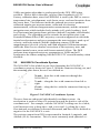
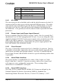
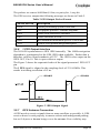
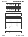
NAV420 Series User’s Manual
Document 7430-0121-01
Preliminary, September 2004
Crossbow Technology, Inc., 41 Daggett Drive, San Jose, CA 95134
Tel: 408-965-3300, Fax: 408-324-4840
email: [email protected], website: www.xbow.com
©2004 Crossbow Technology, Inc. All rights reserved. Information in this
document is subject to change without notice.
Crossbow and SoftSensor are registered trademarks and NAV420CA is a
trademark of Crossbow Technology, Inc. Other product and trade names
are trademarks or registered trademarks of their respective holders.
NAV420CA Series User’s Manual
Table of Contents
1
Introduction........................................................................................... 1
1.1
The NAV420CA Navigation and Attitude Sensing Units ............ 1
1.2
Package Contents.......................................................................... 2
2 Quick Start ............................................................................................ 4
2.1
NAV-VIEW Software................................................................... 4
2.1.1
NAV-VIEW Computer Requirements .................................. 4
2.1.2
Install NAV-VIEW ............................................................... 4
2.2
Connections .................................................................................. 4
2.3
Setting up NAV-VIEW................................................................. 5
2.4
Take Measurements ...................................................................... 5
3 NAV420CA Details.............................................................................. 6
3.1
NAV420CA Architecture ............................................................. 6
3.2
NAV420CA Coordinate System................................................... 7
3.3
Attitude and Heading Determination Algorithm........................... 8
3.3.1
Attitude and Heading Processor............................................ 9
3.3.2
Kalman Filter Attitude and Heading Estimation Model ....... 9
3.3.3
Attitude and Heading Initialization..................................... 10
3.4
Factory Sensor Calibration ......................................................... 11
3.5
Connections ................................................................................ 11
3.5.1
I/O Cable............................................................................. 12
3.5.2
Power Input and Power Input Ground ................................ 12
3.5.3
Case Ground ....................................................................... 12
3.5.4
Serial Data Interface ........................................................... 12
3.5.5
Serial GPS Interface............................................................ 12
3.5.6
1 PPS Output Interface........................................................ 13
3.5.7
GPS Antenna Connection ................................................... 13
3.5.8
No Connection .................................................................... 14
3.5.9
Quick Digital interface connection ..................................... 14
3.6
Measurement Modes................................................................... 14
3.6.1
Scaled Sensor Mode............................................................ 15
3.6.2
AHRS Mode ....................................................................... 15
3.6.3
NAV Mode ......................................................................... 16
3.7
BIT Processing............................................................................ 18
Doc# 7430-0121-01 Preliminary
Page i
NAV420CA Series User’s Manual
4
5
6
7
8
9
3.8
Commands .................................................................................. 19
3.8.1
Input Packets ....................................................................... 19
3.8.2
Output Packets .................................................................... 20
3.8.3
Command List..................................................................... 20
3.9
Data Packet Format..................................................................... 23
3.10 Timing......................................................................................... 25
3.11 Temperature Sensor .................................................................... 26
3.12 Magnetic Heading ....................................................................... 26
NAV420CA Operating Tips ............................................................... 27
4.1
Mounting the NAV420CA.......................................................... 27
Limitations .......................................................................................... 29
5.1
Installation .................................................................................. 29
5.2
Alignment ................................................................................... 29
5.3
Operation in Magnetic Environment........................................... 29
5.4
Range Limitations....................................................................... 29
Appendix A. Mechanical Specifications............................................. 30
6.1
NAV420CA Outline Drawing..................................................... 30
Appendix B. NAV420CA Output Quick Reference ........................... 31
7.1
Digital Output Conversion .......................................................... 31
Appendix C. Hard and Soft Iron Calibration ...................................... 32
8.1
Hard/Soft Iron Calibration Introduction...................................... 32
8.2
NAV420CA Hard and Soft Iron Calibration Procedure ............. 32
8.2.1
Calibration Process Overview using NAV-VIEW .............. 32
8.2.2
Calibration Commands ....................................................... 34
Appendix D. Warranty and Support Information ................................ 36
9.1
Customer Service ........................................................................ 36
9.2
Contact Directory........................................................................ 36
9.3
Return Procedure ........................................................................ 36
9.3.1
Authorization ...................................................................... 36
9.3.2
Identification and Protection ............................................... 37
9.3.3
Sealing the Container .......................................................... 37
9.3.4
Marking............................................................................... 37
9.3.5
Return Shipping Address .................................................... 37
9.4
Warranty ..................................................................................... 37
Page ii
Doc# 7430-0121-01 Preliminary
NAV420CA Series User’s Manual
Doc# 7430-0121-01 Preliminary
Page iii
NAV420CA Series User’s Manual
About this Manual
The following annotations have been used to provide additional
information.
; NOTE
Note provides additional information about the topic.
; EXAMPLE
Examples are given throughout the manual to help the reader understand the
terminology.
3 IMPORTANT
This symbol defines items that have significant meaning to the user
0 WARNING
The user should pay particular attention to this symbol. It means there is a
chance that physical harm could happen to either the person or the
equipment.
The following paragraph heading formatting is used in this manual:
1 Heading 1
1.1 Heading 2
1.1.1 Heading 3
Normal
Page iv
Doc# 7430-0121-01 Preliminary
NAV420CA Series User’s Manual
1
Introduction
1.1 The NAV420CA Navigation and Attitude Sensing Units
This manual explains the use of the NAV420 Series of products, a
combined Navigation and attitude and heading reference system to measure
stabilized pitch, roll and yaw angles in a dynamic environment along with
position and velocity.
Crossbow has been developing low cost solid-state systems that measure
roll, pitch, and heading using MEMS technology in commercial, industrial
and aerospace markets since 1998. The Crossbow Navigation System, or
NAV420CA uses a 3-axis accelerometer and a 3-axis rate sensor to make a
complete measurement of the dynamics of the system. The addition of a 3axis magnetometer inside the NAv420CA allows it to make a true
measurement of magnetic heading without an external flux valve. With the
built-in GPS receiver, the combined system becomes a low-cost INS that
can output location, velocity and acceleration. The Crossbow NAV420CA
is a solid-state equivalent of a vertical gyro/artificial horizon display
combined with a directional gyro, flux valve and Global Positioning System
(GPS).
Crossbow’s newest inertial system, the NAV420CA, combines the latest in
low cost MEMS sensors and digital signal processing techniques to provide
an inexpensive and compact-sized alternative to existing IMU systems.
Closely coupled integration of the sensors, data acquisition elements and a
Kalman filter based algorithm allow the NAV420CA to provide an accurate
representation of the attitude and heading of an object with improved
performance over older technology systems. The integration of a GPS
receiver provides more information for the extended Kalman filter, allowing
it to provide better corrections for attitude determination, as well as the
ability to estimate accelerometer and magnetometer sensor errors.
Furthermore, the digital architecture’s flexible interface allows easy
integration into most applications. The calibrated sensor output (angular
rate, acceleration, and magnetic vector) allows easy integration for control
systems.
The Crossbow NAV420CA is the latest generation of navigation and
attitude and heading reference systems in the DMU family. It has a
sophisticated mechanical and electrical design, and provides stable roll,
pitch and heading measurements under high dynamic conditions.
Furthermore, the device provides a self-tuning system that automatically
compensates for bias in all three gyros and accelerometers. The system can
generate accurate attitude and heading data based on measurements
obtained from commercially available, MEMS performance sensors. The
Doc# 7430-0121-01 Preliminary
Page 1
NAV420CA Series User’s Manual
sensors are factory calibrated on Crossbow test equipment including
calibrated ovens and rate tables. The sensor and system calibration
parameters and temperature compensation curves are written to non-volatile
memory in the system.
The NAV420CA has an RS-232 serial link. Data may be requested via the
serial link as a single polled measurement or may be streamed continuously.
The NAV420CA uses angular rate sensors and linear acceleration sensors
that are bulk machined MEMS devices. Solid-state MEMS sensors make
the NAV420CA both responsive and reliable. The magnetic sensors are
state-of-the-art miniature fluxgate sensors. Fluxgate sensors make the
NAV420CA sensitive and responsive, with better temperature performance
than other technologies such as magneto-resistive sensors. When combined
together with the built-in GPS receiver, it provides a complete navigation
solution.
The NAV420CA utilizes a sophisticated Kalman filter algorithm to allow
the unit to track orientation accurately through dynamic maneuvers. The
Kalman filter will automatically adjust for changing dynamic conditions
without any external user input. No user intervention or configuration is
required at power-up.
The BIT message is included in each packet that provides comprehensive
information into system health. BIT is used for informing the user of the
system status and informing the user of system problems.
The NAV420CA series units are light-weight, low power, fast turn on,
reliable and accurate solutions for a wide variety of stabilization,
navigation, guidance and measurement applications. However, it should not
be exposed to large magnetic fields. This could permanently magnetize
internal components of the NAV420CA and degrade its magnetic heading
accuracy.
1.2 Package Contents
In addition to your NAV420CA sensor product you should have:
•
1 CD with NAV-VIEW Software
NAV-VIEW will allow you to immediately view the outputs of the
NAV420CA on a PC running Microsoft® Windows™. You can
also download this software from Crossbow’s web site at
http://www.xbow.com.
•
1 Digital Signal Cable
This links the NAV420CA directly to a serial port. Only the
transmit, receive, power, and ground channels are used.
•
NAV420 Series User’s Manual
Page 2
Doc# 7430-0121-01 Preliminary
NAV420CA Series User’s Manual
This contains helpful hints on programming, installation, valuable
digital interface information including data packet formats and
conversion factors.
Doc# 7430-0121-01 Preliminary
Page 3
NAV420CA Series User’s Manual
2
Quick Start
2.1 NAV-VIEW Software
Crossbow includes NAV-VIEW software to allow you to use the
NAV420CA right out of the box and the evaluation is straightforward.
Install the NAV-VIEW software, connect the NAV420CA to your serial
port, apply power to your unit and start taking measurements.
2.1.1 NAV-VIEW Computer Requirements
The following are minimum capabilities that your computer should have to
run NAV-VIEW successfully:
•
CPU: Pentium-class
•
RAM Memory: 64MB minimum, 128MB recommended
•
Hard Drive Free Memory: 17MB
•
Operating System: Windows 98, NT4, 2000, XP
2.1.2 Install NAV-VIEW
To install NAV-VIEW in your computer:
1. Insert the CD “Support Tools” in the CD-ROM drive.
2. Find the NAV-VIEW folder. Double click on the setup file.
3. Follow the setup wizard instructions. You will install NAV-VIEW
and a LabVIEW Runtime Engine. You will need both these
applications.
If you have any problems or questions, you may contact Crossbow directly.
2.2 Connections
The NAV420CA is shipped with a cable to connect the NAV420CA to a PC
Serial port.
1. Connect the 15-pin end of the digital signal cable to the port on the
NAV420CA.
2. Connect the 9-pin end of the cable to the serial port of your
computer.
3. The additional black and red wires on the cable supply power the
NAV420CA. Match red to (+) power and black to (-) ground. The
input voltage can range from 9-30 VDC at 350 mA.
4. Bolt the base of the unit to a grounded surface. A good ground is
required for EMI and lightning over-voltage protection.
Page 4
Doc# 7430-0121-01 Preliminary
NAV420CA Series User’s Manual
0 WARNING
Do not reverse the power leads! Applying the wrong power to the
NAV420CA can damage the unit; although there is reverse power
protection, Crossbow Technology is not responsible for resulting damage to
the unit should the reverse voltage protection electronics fail.
2.3 Setting up NAV-VIEW
With the NAV420CA connected to your PC serial port and powered, open
the NAV-VIEW software.
1. NAV-VIEW should automatically detect the NAV420CA and
display the serial number and firmware version if it is connected.
2. If NAV-VIEW does not connect, check that you have the correct
COM port selected. You find this under the “DMU” menu.
3. Select the type of display you want under the menu item
“Windows”. Graph displays a real time graph of all the
NAV420CA data; FFT displays a Fast-Fourier transform of the
data; Navigation shows an artificial horizon display.
4. You can log data to a file by entering a data file name. You can
select the rate at which data is saved to disk.
5. If the status indicator says, “Connected”, you’re ready to go. If
the status indicator doesn’t say connected, check the connections
between the NAV420CA and the computer; check the power;
check the serial COM port assignment on your computer.
2.4 Take Measurements
Once you have configured NAV-VIEW to work with your NAV420CA,
pick what kind of measurement you wish to see. “Graph” will show you the
output you choose as a strip-chart type graph of value vs. time. “FFT” will
show you a real-time Fast-Fourier transform of the output you choose.
“Navigation” will show an artificial horizon and the stabilized roll, pitch
and heading output of the NAV420CA. When GPS is available, and NAV
packet is chosen, “GPS” will show a digital display of latitude, longitude
and altitude and strip chart type graph of velocity vs. time.
Let the NAV420CA warm up for 60 seconds when first turned on. This
allows the Kalman filter to estimate the rate sensor biases. The
NAV420CA needs to be held still (motionless) during this period. Now
you’re ready to use the NAV420CA!
Doc# 7430-0121-01 Preliminary
Page 5
NAV420CA Series User’s Manual
3
NAV420CA Details
3.1 NAV420CA Architecture
The NAV420CA is an intelligent attitude gyro for roll, pitch and directional
gyro for heading angle measurements in dynamic environments. The unit is
also a nine-axis measurement system that outputs accurate acceleration,
angular rates and magnetic orientation. The NAV420CA uses the latest in
solid-state sensor technology resulting in superior performance, reliability,
and stability over time and operating environments.
The NAV420CA consists of the following subsystems:
1) Inertial Sensor Array: This is an assembly of three accelerometers,
three gyros (rate sensors) and four temperature sensors.
2) A three axis fluxgate magnetometer board used to compute
heading.
3) A WAAS capable GPS receiver for position and velocity
measurement.
4) A digital processing PCB, which receives the signals from the
inertial sensors and magnetometers. This unit converts these
signals to digital data, filters the data, computes the attitude
solution, monitors and processes all BIT data, and transmits the
results to the user.
These blocks are shown in the system block diagram below in Figure 1.
Digital Outputs
X / Y / Z Acceleration
X/Y/Z
High-Speed
Gyros
Sampling &
DSP
(MEMS)
Roll / Pitch / Yaw Rate
RS-232
Roll / Pitch / Yaw Angle
+
X/Y/Z
16-BIT
Accelerometers
A/D
X / Y / Z Magnetic Field
Position / Velocity
Sensor
Built-In-Test
Compensation
+
(MEMS)
Full-State
X/Y/Z
Kalman Filter
Magnetometers
(Flux Gate)
Temperature
GPS Antenna
GPS Receiver
Power
Power Input
Conditioning
+ 9 TO +30 VDC
Figure 1 NAV420CA System Architecture
The NAV420 analog sensor set is converted to digital data at 1 kHz. The
sensor data is filtered and down-sampled by a DSP using FIR filters. The
Page 6
Doc# 7430-0121-01 Preliminary
NAV420CA Series User’s Manual
100Hz navigation algorithm is synchronized to the GPS 1PPS when
available. Packet data is therefore valid on 10ms boundaries of UTC.
Factory calibration data, stored in EEPROM, is used by the DSP to remove
temperature bias, misalignment, scale factor errors, and non-linearities from
the sensor data. The firmware inside the onboard processors produces
calibrated angular rate measurements, calibrated acceleration
measurements, calibrated magnetometer measurements, and the estimated
navigation state which includes body attitude (roll, pitch, heading), local
level horizontal navigation frame position (latitude, longitude, and altitude)
and velocity. The algorithm used to estimate the navigation state is an
Extended Kalman Filter (EKF) trajectory correction approach in which the
inertial accelerometers and gyros propagate the state trajectory made up of
velocity, and body attitude, and the supporting sensors (GPS and
magnetometers) provide velocity and earth magnetic field measurements
which the filter uses to calculate corrections to the trajectory state, and
estimate inertial sensor errors and ferrous material effects. The DSP
performs time-triggered trajectory propagation at 100Hz and will
synchronize the sensor sampling with the GPS UTC second boundary when
available.
3.2 NAV420CA Coordinate System
The NAV420CA has a label on one face illustrating the NAV420CA
coordinate system as shown in Figure 2. With the connector facing you, and
the mounting plate down, the axes are defined as:
X-axis – from face with connector through the
NAV420CA
Y-axis – along the face with connector from left to
right
Z-axis – along the face with the connector from top to
bottom
Figure 2 NAV420CA Coordinate System
The axes form an orthogonal right-handed coordinate system. An
acceleration is positive when it is oriented towards the positive side of the
coordinate axis. For example, with the NAV420CA sitting on a level table,
it will measure zero g along the x- and y-axes and -1 g along the z-axis.
Gravitational acceleration is directed downward, and thus will be defined as
negative for the NAV420CA z-axis.
The position output from GPS is represented in Latitude, Longitude, and
Altitude (LLA) convention. This is a most commonly used spherical co-
Doc# 7430-0121-01 Preliminary
Page 7
NAV420CA Series User’s Manual
ordinate system. The GPS velocity is defined in North, East and Down
reference frame. The users can convert this into Cartesian coordinate
system, called Earth-Centered, Earth-Fixed (ECEF). ECEF uses threedimensional XYZ coordinates (in meters) to describe the location of a GPS
user or satellite. Several online resources are available to help users with
this transformation. For example, refer to the application note on Crossbow
website, http://www.xbow.com/Support/appnotes.htm
The angular rate sensors are aligned with these same axes. The rate sensors
measure angular rotation rate around a given axis. The rate measurements
are labeled by the appropriate axis. The direction of a positive rotation is
defined by the right-hand rule. With the thumb of your right hand pointing
along the axis in a positive direction, your fingers curl around in the
positive rotation direction. For example, if the NAV420CA is sitting on a
level surface and you rotate it clockwise on that surface, this will be a
positive rotation around the z-axis. The x- and y-axis rate sensors would
measure zero angular rates, and the z-axis sensor would measure a positive
angular rate.
The magnetic sensors are aligned with the same axes definitions and sign as
the linear accelerometers. For example, when oriented towards magnetic
North, you will read approximately +0.25 Gauss along X, 0.0 Gauss along
Y, and +0.35 Gauss along Z direction (North America).
Pitch is defined positive for a positive rotation around the y-axis (pitch up).
Roll is defined as positive for a positive rotation around the x-axis (roll
right). Yaw is defined as positive for a positive rotation around the z-axis
(turn right).
The angles are defined as standard Euler angles using a 3-2-1 system. To
rotate from the body frame to an earth-level frame, roll first, then pitch, and
then yaw.
3.3 Attitude and Heading Determination Algorithm
The attitude and heading determination algorithm is divided into two
separate entities. Gyro measured angular rate information is integrated in
an attitude trajectory propagation model, and attitude errors and gyro biases
are estimated in a Kalman Filter Attitude and Heading Estimation Model.
Both gyros and accelerometers suffer from bias drift, misalignment errors,
acceleration errors (g-sensitivity), nonlinearity (square terms), and scale
factor errors. The magnetometers are also susceptible to magnetic
disturbances, which corrupt their measurement of the earth magnetic field.
These errors, typically known as hardiron and softiron effects, are calibrated
out once the system is installed in its final mounting position. The largest
error in attitude and heading propagation is associated with the gyro bias
terms. The Kalman filter attitude estimation component provides an on-the-
Page 8
Doc# 7430-0121-01 Preliminary
NAV420CA Series User’s Manual
fly calibration for the gyros by providing corrections to the attitude
processor trajectory and a characterization of the gyro bias state. The
accelerometers provide an attitude reference using gravity, and the
magnetometers provide a heading reference using the earth’s magnetic field
vector. The NAV420 runs a 7 state AHRS type EKF when GPS is down
and a 13 state reduced navigation filter (loosely coupled) when GPS is up.
The quality of the NAV420’s low-cost MEMS inertial sensors makes
double integration for position tracking of marginal value and thus, only
velocities are tracked in the filter. The tangent frame is used as the
navigation frame and earth rate is not considered. By reducing the
navigation filter to this minimalist form, we are able to sample the sensor
set at 1 kHz and run the navigation filter at 50 Hz.
3.3.1 Attitude and Heading Processor
The data processor attitude estimation algorithm provides stable Euler roll,
pitch, and yaw angles. For improved accuracy and to avoid singularities
when dealing with the cosine rotation matrix, a quaternion formulation is
used in the algorithm to provide attitude propagation. The body angular
rates are then sensed by the gyros and a differential equation describing the
propagation of the quaternion is integrated using Runge-Kutta algorithm to
obtain the propagated quaternion. The cosine rotation matrix is obtained
from the quaternion, which then defines the attitude roll, pitch, and yaw
angles. With GPS up, the NAV420 tracks rate sensor bias, accelerometer
bias, quaternion attitude, and tangent frame velocities. Propagating tangent
frame velocities directly avoids transformations to and from non-Euclidean
coordinate systems. Eliminating position states from the navigation filter
nearly cuts processing requirements in half because the state covariance
update is Θ( n ) . The state model can seamlessly switch between the
reduced navigation filter and an AHRS type filter based on the health of the
GPS receiver.
3
3.3.2 Kalman Filter Attitude and Heading Estimation Model
The Kalman filter attitude correction approach achieves improved
performance due to its ability to estimate the attitude errors and gyro bias
states. The advantage with this approach is that an absolute attitude error
estimate is provided to the trajectory to correct any errors due to physical
noise disturbances and gyro errors, as well as a characterization and
“tracking” of the gyro biases which in effect provides an online rate sensor
calibration. The filter model is an Extended Kalman Filter formulation
made up of two components, a linearized attitude error and gyro bias state
model, and a nonlinear attitude quaternion error measurement model. The
state model predicts where the attitude errors and gyro bias states will
Doc# 7430-0121-01 Preliminary
Page 9
NAV420CA Series User’s Manual
propagate based on input data from the gyros, and the measurement model
corrects this prediction with the real world attitude error measurements
obtained from the accelerometer gravity and magnetometer earth magnetic
field reference. This balance of state modeling with real world observables
gives the Kalman filter the adaptive intelligence to assign appropriate
confidence levels on its two components.
The NAV420CA blends GPS, magnetometer, and accelerometer tilt
measurements into the EKF update depending on the health and status of
the associated sensors. The NAV420CA uses the GPS receiver’s tangent
frame velocity estimate as a direct measurement update for the EKF. In this
way, the NAV420CA utilizes the GPS receiver’s internal ECEF to tangent
frame velocity transformation resulting in a computationally efficient
measurement update.
The NAV420CA uses its internal magnetometers to provide a heading
measurement update for the EKF. Magnetometer measurements are
calibrated, corrected for hardiron and softiron effects from the local
environment, and rotated to the tangent frame. The World Magnetic Model
(WMM) 2000 is used to calculate the relationship between magnetometer
heading and true heading, known as magnetic declination or variance. GPS
position is used to calculate the tangent frame earth magnetic field vector
from the WMM and the declination angle is computed from the WMM
horizontal components. The magnetometer measurements can then be
rotated through the declination angle to provide a true heading
measurement. The true heading measurement’s nonlinear relationship to
the quaternion attitude is captured by the EKF measurement model to create
a linearized filter update.
If the GPS link is lost or poor, the Kalman Filter solution stops tracking
accelerometer bias. The algorithm continues to apply gyro bias correction
and provides stabilized angle outputs. The EKF tracking states are reduced
to angles and gyro bias only. The accelerometers will continue to integrate
velocity, however, accelerometer noise, bias, and attitude error will cause
the velocity estimates to walk off on the order of seconds. The attitude
tracking performance will degrade and the filter will become susceptible to
“false gravity” acceleration errors, typical of the AHRS only EKF
formulation. The UTC packet synchronization will drift due to internal
clock drift.
3.3.3 Attitude and Heading Initialization
Immediately after power-up, the NAV420CA uses the accelerometers and
magnetometers to compute the initial angles (roll, pitch and yaw). The roll
and pitch attitude will be initialized using the accelerometer’s reference of
gravity, and yaw will be initialized using the leveled magnetometers X and
Page 10
Doc# 7430-0121-01 Preliminary
NAV420CA Series User’s Manual
Y axis reference of the earth’s magnetic field. For this same reason, the
NAV420CA needs to be held motionless for 60 sec upon power up for the
initialization to complete.
3.4 Factory Sensor Calibration
A calibration procedure performed at the factory will provide correction
parameters for the following static and dynamic errors for each sensor. The
software will then apply these parameters to each sensor to provide a
correction for the errors:
•
Rate sensors are calibrated for temperature bias, scale factor, and
misalignment.
•
Accelerometers are calibrated for temperature bias, scale factor,
and misalignment.
• Magnetometers are calibrated for bias, and scale factor.
Sensor errors are compensated for these effects using a proprietary
algorithm from data collected during manufacturing. Accelerometer, rate
gyro, and magnetometer sensor bias shifts over temperature (-40 0C to +71
0
C) are compensated and verified using a thermal chamber and rate table.
3.5 Connections
The NAV420CA has a male DB-15 connector. The signals are as shown in
Table 1.
Table 1 Connector Pin Assignments
Pin
Signal
1
RS-232 Transmit Data
2
RS-232 Receive Data
3
Positive Power Input (+Vcc)
4
Power Ground
5
Chassis Ground
6
NC – Factory use only
7
RS-232 GPS Tx
8
RS-232 GPS Rx
9
Signal Ground
Doc# 7430-0121-01 Preliminary
Page 11
NAV420CA Series User’s Manual
10
1 PPS OUT
11
NC – factory use only
12
NC – factory use only
13
NC – factory use only
14
NC – factory use only
15
NC – factory use only
3.5.1 I/O Cable
The user must provide a shielded cable with the shield connected to the I/O
connector shell in order to provide the required EMI protection. The cable
sent with the unit is intended to provide the user with the ability to test the
unit right out of the box, and will not provide adequate shielding for all
environments. Case ground (see below) must be used to provide full EMI
protection.
3.5.2 Power Input and Power Input Ground
Power is applied to the NAV420CA on pins 3 and 4. Pin 4 is ground; Pin 3
should have 9 to 30 VDC unregulated at 350 mA. If you are using the cable
supplied with the NAV420CA, the power supply wires are broken out of the
cable at the DB-9 connector. The red wire is connected to the positive
power input; the black wire is connected to the power supply ground. DO
NOT REVERSE THE POWER LEADS.
3.5.3 Case Ground
The case is electrically connected to Pin 5 of the DB-15 connector. The Pin
5 should be electrically connected to the user’s cable shield, especially if the
chassis does not make good ground contact. The case is isolated from the
Power Input Ground, and should be bolted to a good conducting surface that
is grounded.
3.5.4 Serial Data Interface
The serial interface is standard RS-232, 9600, 19200, 38400, or 57600
baud, 8 data bits, 1 start bit, 1 stop bit, no parity, and no flow control and
will output at a user configurable output rate. These settings allow
interaction via a standard PC serial port.
3.5.5 Serial GPS Interface
The GPS receiver outputs data in NEMA-0183 format as defined by the
National Marine Electronics Association (NMEA), Standard For
Interfacing Marine Electronic Devices, Version 2.20, January 1, 1997.
Page 12
Doc# 7430-0121-01 Preliminary
NAV420CA Series User’s Manual
The packets are sent at 9600 Baud, 8 bits, no parity bit, 1 stop bit.
The GPS receiver outputs the following messages as shown in Table 2.
Table 2 GPS Output Packet Format
NEMA Record
GGA
GLL
GSA
GSV
RMC
VTG
Description
Global positioning system fixed data
Geographic position - latitude/longitude
GNSS DOP and active satellites
GNSS satellites in view
Recommended minimum specific GNSS data
Course over ground and ground speed
3.5.6 1 PPS Output Interface
The NAV420 synchronizes to GPS 1PPS internally. The 100Hz navigation
algorithm is synchronized to the GPS 1PPS when available. Packet data is
therefore valid on 10ms boundaries of UTC. The 1PPS is also output on the
1PPS OUT, Pin 10. This is open collector output.
The Figure 3 shows the sequential order of the signal present at 1 PPS OUT
pin.
The 1 PPS signal is aligned to the sampling clock of 23.104 MHz. This
results in a timing resolution of 43 ns.
Figure 3 1PPS Output Signal
3.5.7 GPS Antenna Connection
A GPS needs to receive signals from as many satellites as possible. A GPS
receiver doesn’t work properly in narrow streets and underground parking
lots or if objects or human beings cover the antenna. Poor visibility may
Doc# 7430-0121-01 Preliminary
Page 13
NAV420CA Series User’s Manual
result in position drift or a prolonged Time-To-First-Fix (TTFF). A good
sky visibility is therefore a prerequisite. Even the best receiver can’t make
up for signal loss due to a poor antenna, in-band jamming or a bad RFboard design.
The NAV420CA unit ships with an external active antenna that must be
connected properly to SMA jack located next to the DB-15 connector.
3 IMPORTANT
Place the antenna with optimal sky visibility.
3.5.8 No Connection
During normal operation of the NAV420CA, no connection is made to the
factory test pins. These pins have internal pull-up mechanisms and must
have no connections for the NAV420CA to operate properly.
3.5.9 Quick Digital interface connection
On a standard DB-9 COM port connector, make the connections as
described in Table 3.
Table 3 DB-9 COM Port Connections
COM Port Connector
Pin #
Signal
NAV420CA Connector
Pin #
1
Signal
2
RxD
TxD
3
TxD
2
RxD
5
GND
9
GND
Power is applied to the NAV420CA on pins 3 and 4. Pin 4 is power
ground; Pin 3 should have 9-30 VDC unregulated at 350 mA. DO NOT
REVERSE THE POWER LEADS.
3.6 Measurement Modes
The NAV420CA is designed to operate as a complete attitude and heading
reference system. You can also use this as a nine-axis sensor module. The
NAV420CA can be set to operate in one of three modes: Scaled Sensor
mode, AHRS mode, or NAV mode. The measurement mode selects the
information that is sent in the data packet over the RS-232 interface. See
the “Data Packet Format” section for the actual structure of the data packet
in each mode. The default system operation is “NAV” mode.
Page 14
Doc# 7430-0121-01 Preliminary
NAV420CA Series User’s Manual
3.6.1 Scaled Sensor Mode
In Scaled Sensor mode, the analog sensors are sampled, converted to digital
data, temperature compensated, corrected for misalignment, and scaled to
engineering units. The digital data represents the actual value of the
quantities measured. A calibration table for each sensor is stored in the
NAV420CA non-volatile memory. A single data packet can be requested
using a serial poll command or the NAV420CA can be set to continuously
output data packets to the host. The data is sent as signed 16-bit 2’s
complement integers. In this mode, the NAV420CA operates as a nine-axis
measurement system.
The scaled sensor outputs are enabled in this mode. Note that stabilized
pitch, roll, and yaw angles are not available in scaled sensor mode.
To convert the acceleration data into G’s, use the following conversion:
accel = data*(10)/215
where accel is the actual measured acceleration in G’s, data is the digital
data sent by the NAV420CA, and 10 is the G Range for your NAV420CA.
(The data is scaled so that 1 G = 9.81 m s-2.) This maximum G range is a
default value.
To convert the angular rate data into degrees per second, use the following
conversion:
rate = data*(630)/215
where rate is the actual measured angular rate in °/sec, data is the digital
data sent by the NAV420CA, and 630 is the Angular rate Range of the
NAV420CA. This maximum angular rate range is a default value.
To convert the magnetometer data into Gauss, use the following conversion:
mag = data*(1.0)/215
where mag is the actual measured magnetic field in Gauss, data is the
digital data sent by the NAV420CA, and 1.0 is the Magnetic field Range of
the NAV420CA. This maximum magnetometer range is a default value.
The Kalman filter is enabled in scaled sensor mode, however, the sensors
outputs are not corrected by Kalman filter bias estimates in the scaled
sensor output packet. Therefore, the rate sensor bias will change slightly
due to changes in temperature and time.
3.6.2 AHRS Mode
In AHRS mode, the NAV420CA acts as a complete attitude and heading
reference system and outputs the stabilized pitch, roll, and yaw angles along
with the angular rate, acceleration, and magnetic field information. The
angular rate, acceleration, and magnetic field values are calculated as
described in the Scaled Sensor mode.
Doc# 7430-0121-01 Preliminary
Page 15
NAV420CA Series User’s Manual
The Kalman filter operates using an AHRS type filter if GPS is down or a
reduced state navigation filter if GPS is up. When GPS is down, the filter
tracks the rate sensor bias and calculates stabilized roll, pitch, and yaw
angles.
The NAV420CA uses the angular rate sensors to integrate over your
rotational motion and find the actual pitch, roll, and yaw angles. When
GPS is down, the NAV420CA uses the accelerometers to correct for rate
sensor drift in the vertical angles (pitch and roll); the NAV420CA uses the
magnetometers to correct for rate sensor drift in the yaw angle. This is the
modern equivalent of an analog vertical gyro that used a plumb bob in a
feedback loop to keep the gyro axis stabilized to vertical. The NAV420CA
takes advantage of the rate gyros’ sensitivity to quick motions to maintain
an accurate orientation when accelerations would otherwise throw off the
accelerometers measurement of the NAV420CA orientation relative to
gravity; the NAV420CA then uses the accelerometers to provide long term
stability to keep the rate gyro drift in check when GPS is down.
The NAV420CA uses a sophisticated Kalman filter algorithm to track the
bias in the rate sensors and accelerometers. This allows the NAV420CA to
use a very low effective weighting on the accelerometers when the
NAV420CA is moved. This makes the NAV420CA very accurate in shortterm dynamic maneuvers regardless of GPS status.
The NAV420CA outputs the stabilized pitch, roll and yaw angles in the
digital data packet in AHRS mode.
To convert the digital data to angle, use the following relation:
angle = data*(SCALE)/215
where angle is the actual angle in degrees (pitch, roll or yaw), data is the
signed integer data output in the data packet, and SCALE is a constant.
SCALE = 180° for roll, pitch and yaw.
3.6.3 NAV Mode
When GPS is up, the NAV420CA acts as a complete navigation and attitude
and heading reference system. The NAV packet outputs the stabilized
pitch, roll, and yaw angles, longitude, latitude, altitude, GPS velocity along
with the angular rate information. The roll, pitch, yaw, and angular rate
values are calculated as described in the Scaled Sensor and AHRS modes.
The Kalman filter operates in NAV mode when GPS is up to track the rate
sensor bias, accelerometer bias, NED velocities, and stabilized roll, pitch,
and yaw angles.
In NAV mode, the NAV420CA uses the angular rate sensors to integrate
over your rotational motion and find the actual pitch, roll, and yaw angles.
The NAV420CA uses the accelerometers indirectly to correct for rate
Page 16
Doc# 7430-0121-01 Preliminary
NAV420CA Series User’s Manual
sensor drift in the vertical angles (pitch and roll); the NAV420CA uses the
magnetometers to correct for rate sensor drift in the yaw angle; the
NAV420CA uses the GPS velocity to correct the NED velocity trajectory,
accelerometer bias, rate sensor drift, and attitude.
The NAV420CA uses a sophisticated Kalman filter algorithm to track the
bias in the rate sensors and accelerometers. This allows the NAV420CA to
use a very low effective weighting on the Kalman filter measurements from
GPS and magnetometers when the NAV420CA is moved. This makes the
NAV420CA very accurate in extended dynamic and static maneuvers when
GPS is up.
The NAV420CA outputs GPS Longitude/Latitude/Altitude and NED
velocity in the NAV digital data packet when GPS is up.
The GPS Longitude/Latitude is a 4-byte data and to convert it into degrees,
lon/lat = data*(SCALE)/231
where, lon/lat is the actual Longitude/ Latitude, data is the signed integer
data output in the data packet, and SCALE is a constant. SCALE = 1800 to
convert into degrees.
The GPS Altitude is a 2-byte data and to convert it into meters,
If(data<-400) alt = (unsigned) data*(SCALE)/215
Else alt = (signed) data*(SCALE)/215
where, alt is the actual Altitude, data is the signed or unsigned integer data
output in the data packet, and SCALE is a constant. SCALE = 16384 to
convert into meters. Note in Table 5-3 that the range on altitude is not
symmetric about zero. Thus, a range check must be performed to interpret
the altitude data correctly.
The velocity is a 2-byte data and to convert it into m/sec,
vel = data*(SCALE)/215
where, vel is the actual velocity measured in m/sec, data is the signed
integer data output in the data packet, and SCALE is a constant. SCALE =
256 m/sec.
If the GPS signal is lost or poor, the velocity is computed using free
integration of accelerometer outputs, the accuracy of which will degrade if
the GPS signal is lost for extended periods of time. The last known good
GPS position is sent in the data packet while the system believes there is a
GPS outage. The yaw angle output will continue with reference to true
north using the last known magnetic declination angle.
Doc# 7430-0121-01 Preliminary
Page 17
NAV420CA Series User’s Manual
3.7 BIT Processing
The BIT message in each packet provides comprehensive information into
system health. BIT is used for informing the user of the system status and
informing the user of system problems.
The following information is supplied in the BIT byte fields of the data
packet. The table 4 contains the actual bit definition present in the two-byte
output BIT field in the angle mode data packet (see section 3.9 below).
Table 4 Bit Message Definition
Bit
0
1
2
3
4
BIT Data
Reserved
Reserved
Reserved
Turn
Detect
Comm
Transmit
Error
5
6
Reserved
GPS Status
7
8
Reserved
Algorithm
Initialization
9
1 PPS Signal
Lock
10
Reserved
11
MagAlign
Valid
12
User Port
Comm
Page 18
Description
0: Yaw rate magnitude < 0.4 deg/sec.
1: Unit is executing a turn
0: No serial port transmit communication failure
has been detected
1: A serial port transmit communications failure
has been detected such as overrun, parity
0: GPS 3D solution is valid
1: GPS unlocked or data packet not present.
0: 30-sec. initialization complete
1: Not ready, waiting for power-up, and
initialization completion.
0: GPS 1 PPS signal locked
1: GPS 1 PPS signal not locked
0: Magnetometer hardiron/softiron alignment
valid
1: Magnetometer hardiron/softiron alignment
invalid
0: No user port receive communication failure
has been detected
Doc# 7430-0121-01 Preliminary
NAV420CA Series User’s Manual
Receive Error
13
14, 15
Reserved
Algorithm
Accuracy
1: A user port receive communications failure
has been detected
00 – GPS up, full accuracy NAV,
01 -- low accuracy NAV/high accuracy AHRS,
02 – low accuracy AHRS
03 – AHRS initialization
3.8 Commands
The NAV420CA has a simple command packet structure. You send a
command to the NAV420CA over the RS-232 interface and the
NAV420CA will execute the command. All communications to and from
the unit are packets that start with a single word alternating bit header
0x5555. This is the ASCII string “UU”. All communications packets
except for the ping command and response end with a single word
checksum. The checksum is calculated in the following manner:
1. Sum all packet contents except header and checksum.
2. Divide the sum by 0x10000.
3. The remainder should equal the checksum.
NAV-VIEW is a very good tool to use when troubleshooting your device.
NAV-VIEW formulates the proper command structures and sends them
over the RS-232 interface. You can use NavView to verify that the
NAV420CA is functioning correctly. NavView does not use any
commands that are not listed here.
3.8.1 Input Packets
All communications sent to the unit except for the ping command are input
packets with the following format:
UU
<2-byte command>
<variable length data>
<2-byte checksum>
This generalized input structure allows input commands to carry data for
advanced user interaction. All input packets can be no longer than 128
bytes. All 2-byte input commands consist of a pair of ASCII characters. As
a semantic aid consider the following single character acronyms:
P = packet
F = fields (these are settings or data contained in the unit)
R = read (pertains to default non-volatile fields)
G = get (pertains to current fields or settings)
W = write (pertains to default non-volatile fields)
Doc# 7430-0121-01 Preliminary
Page 19
NAV420CA Series User’s Manual
S = set (pertains to current fields or settings)
G and S refer to current fields. Modifying current fields with S take effect
immediately and are lost on a power cycle. R and W refer to default power
up fields. These fields are stored in non-volatile memory and determine the
unit’s behavior on power up. Modifying default fields take effect on the
next power up and thereafter.
There are 4 user input commands: PK, GP, WF and SF.
; NOTE
The NAV420CA commands are case sensitive!
3.8.2 Output Packets
All communications received from the unit except for the ping response are
output packets with the following format:
UU
<1-byte packet type>
<variable length data>
<2-byte checksum>
All packet types will be single printable ASCII characters. All output
packets can be no longer than 128 bytes.
There are 5 output packet types: P, D, S, A and N. The P is response type
packet, which is sent in response to Ping request. The remaining packets
are available using the get packet command (polling) or can be configured
for continuous (fixed rate) output.
3.8.3
Command List
Command
Ping
Input
Packet
UU
PK
Response
Packet
UU
P
Description
Pings NAV420CA to verify communications. The ping
command does not have data or a checksum to facilitate
human interaction from a keyboard. Sending the ping
command will cause the unit to send a ping response. All
bytes sent and received during the ping command and
responses are ASCII printable characters.
Command
Request Data
Page 20
Doc# 7430-0121-01 Preliminary
NAV420CA Series User’s Manual
Input
Packet
UU
GP
1
<packet type>
Checksum
Response
Packet
Data Packet (See Table 5)
Description
This command allows the user to poll for non response-type
output packets. The packet type options available are: S –
Scaled Sensor Packet; A – AHRS Packet; N – NAV Packet
Refer to Table 5 for data packet format in different modes.
Command
Query Serial Number and Firmware Version
Input
Packet
UU
GP
D
Checksum
Response
Packet
UU
D
Serial Number
Version String
Checksum
Description
This queries the NAV420CA for its serial number and
firmware version. The serial number contains 4-bytes and
should be interpreted as a 32-bit unsigned integer. For
example, the serial number 4003012 would be sent as the
four bytes 00 3D 14 C4.
The firmware version is an ASCII string that describes the
NAV420CA firmware version.
Command
Write/Set Fields
Input
Packet
UU
WF
or
SF
<1-byte num
of fields>
<list of
fields>
<field
data>
Checksum
Response
None
Description
This command allows the user to write default power-up
configuration fields to the EEPROM (WF) or set the unit’s
current configuration (SF) fields, which will be lost on
power down. Writing the default configuration will not take
affect until the unit is power cycled. Num of fields is the
number of words to be written/set. The list of fields are the
field IDs that will be written with the field data,
respectively. The unit will not write to calibration or
algorithm fields. The unit will not respond.
Command
Change Baud Rate
Doc# 7430-0121-01 Preliminary
Page 21
NAV420CA Series User’s Manual
Input
Packet
UU
WF
0x01
0x0002
Value
Checksum
Response
None
Description
This change the default power-up baud rate of the
NAV420CA. Upon sending the command, power cycle the
unit for the change to take effect. The available Value
options are corresponding baud rates are listed below:
Value
0x00
0x01
0x02
0x03
Command
Input
Packet
Baud Rate
9600
19200
38400
57600
Change Packet Type
UU
WF or
SF
0x01
0x0003
Value
Checksum
Response
None
Description
This command allows the user to change the measurement
mode. If you want change the packet type only temporarily,
use SF instead of WF in the command packet above. The
available Value options are corresponding power-up modes
are listed below:
Value
‘S’
‘A’
‘N’
Command
Input
Packet
Measurement Mode
Scaled
Angle
NAV
Change Packet Output Rate
UU
WF or SF
0x01
0x0001
Value
Checksum
Response
None
Description
This command allows the user to change the packet output
rate. If you want change the packet type only temporarily,
use SF instead of WF in the command packet above. The
available Value options are corresponding power-up modes
are listed below:
Page 22
Doc# 7430-0121-01 Preliminary
NAV420CA Series User’s Manual
Value Output Rate
0x00
Quiet
0x01
100 Hz
0x02
50 Hz
0x04
25 Hz
0x05
20 Hz
0x10
10 Hz
0x50
2 Hz
When the output rate is set to Quiet, the unit goes into Polled
mode.
3.9 Data Packet Format
In general, the digital data representing each measurement is sent as a 16-bit
number (two bytes) except for GPS latitude/longitude. The GPS
latitude/longitude is sent as 32-bit number (four bytes).
The data generally represents a quantity that can be positive or negative.
Each data packet will begin with a two-byte header (hex 55 55) and end
with a two-byte checksum. The checksum is calculated in the following
manner:
1. Sum all packet contents except header and checksum.
2. Divide the sum by hex 10000.
3. The remainder should equal the checksum.
The packet also contains the packet type field, and the BIT word output.
Refer to section 3.7 for details about the BIT word processing.
Table 5 NAV420CA Series Data Packet Format
Bytes
0,1
2
5-1 Scaled Sensor Mode Packet
Description
Range
Units
Header (0x5555)
‘S’
3,4
X-Axis Acceleration
[-10, 10]
G
5,6
Y-Axis Acceleration
[-10, 10]
G
7,8
Z-Axis Acceleration
9,10
Roll Angular Rate
11,12
Pitch Angular Rate
[-630, 630]
deg/sec
13,14
Yaw Angular Rate
[-630, 630]
deg/sec
Doc# 7430-0121-01 Preliminary
[-10, 10]
G
[-630, 630]
deg/sec
Page 23
NAV420CA Series User’s Manual
15,16
X-Axis Magnetic Field
[-1, 1]
Gauss
17,18
Y-Axis Magnetic Field
[-1, 1]
Gauss
19,20
Z-Axis Magnetic Field
[-1, 1]
Gauss
21,22
X-Axis Temperature
[-100, 100]
0
C
23,24
Y-Axis Temperature
[-100, 100]
0
C
25,26
Z-Axis Temperature
[-100, 100]
0
C
27,28
CPU Board Temperature
[-100, 100]
0
C
29,30
GPS ITOW (last 2 bytes)
[0, 65536]
31,32
BIT
33,34
Checksum
Bytes
0,1
2
Range
Units
Header (0x5555)
‘A’
3,4
Roll Angle
[-180, 180]
deg
5,6
Pitch Angle
[-180, 180]
deg
7,8
Heading Angle (mag north)
[-180, 180]
deg
9,10
Roll Angular Rate
[-630, 630]
deg/sec
11,12
Pitch Angular Rate
[-630, 630]
deg/sec
13,14
Yaw Angular Rate
[-630, 630]
deg/sec
15,16
X-Axis Acceleration
[-10, 10]
G
17,18
Y-Axis Acceleration
[-10, 10]
G
19,20
Z-Axis Acceleration
[-10, 10]
G
21,22
X-Axis Magnetic Field
[-1, 1]
Gauss
23,24
Y-Axis Magnetic Field
[-1, 1]
Gauss
25,26
Z-Axis Magnetic Field
[-1, 1]
Gauss
27,28
Temperature
[-100, 100]
29,30
GPS ITOW (last 2 bytes)
[0, 65536]
31,32
BIT
33,34
Checksum
Bytes
5-3 NAV Mode Packet
Description
Range
0,1
2
Page 24
5-2 AHRS Mode Packet
Description
msec
0
C
msec
Units
Header (0x5555)
‘N’
Doc# 7430-0121-01 Preliminary
NAV420CA Series User’s Manual
3,4
Roll Angle
[-180, 180]
deg
5,6
Pitch Angle
[-180, 180]
deg
7,8
Heading Angle (true north)
[-180, 180]
deg
9,10
Roll Angular Rate
[-630, 630]
deg/sec
11,12
Pitch Angular Rate
[-630, 630]
deg/sec
13,14
Yaw Angular Rate
[-630, 630]
deg/sec
15,16
X-Axis Velocity (North)
[-256, 256]
m/sec
17,18
Y-Axis Velocity (East)
[-256, 256]
m/sec
19,20
Z-Axis Velocity (Down)
[-256, 256]
m/sec
21,22,23,24
Longitude
[-180, 180]
deg
25,26,27,28
Latitude
[-180, 180]
deg
29,30
Altitude
[-100, 16284]
m
31,32
GPS ITOW (last 2 bytes)
[0, 65536]
msec
33,34
BIT
35,36
Checksum
3.10 Timing
The NAV420CA default data output is NAV packet at 50 packets per
second. Depending on the configuration field set for update rate, the unit
can be made to output at a different constant output rate or not at all for
polled operation.
In some applications, using the NAV420CA’s digital output requires a
precise understanding of the internal timing of the device. The processor
internal to the NAV420CA runs in a time-triggered loop - collecting data
from the sensors, processing the data, and then producing the output packet.
The data is streamed to the user through a parallel process on the serial port.
If GPS 1PPS is available, the internal time-triggered loop is synchronized to
the 1PPS second boundary. Therefore, data packets contain information
valid at 10ms boundaries of the GPS UTC time-pulse.
The unit goes through three processes in one data cycle. First, the sensors
are down-sampled from 1kHz to 100Hz. Second, the unit processes the
data for output using the calibration and navigation algorithms. After
processing the data, the NAV420CA will buffer the serial data. Third, the
unit actually transfers the data out over the RS-232 port at the selected baud
rate, while processing continues.
GPS ITOW (International Time of Week) is available in selected output
packets. The internal GPS is operating at 4Hz and thus, ITOW is updated at
that rate. Only the lower two bytes of GPS ITOW is available due to baud
rate limitations.
Doc# 7430-0121-01 Preliminary
Page 25
NAV420CA Series User’s Manual
3.11 Temperature Sensor
The NAV420CA has onboard temperature sensors. The temperature
sensors are used to monitor the internal temperature of the NAV420CA to
allow for temperature calibration of the sensors. The temperature sensor is
specified to be within ± 2% accurate over the NAV420CA operating
temperature range.
The NAV420CA will output the temperature sensor readings (Scaled
Sensor and AHRS modes) in the digital data packet scaled as follows:
Temp (0C) = data * 100/215
where data is the 16-bit unsigned integer sent as the temperature
information in the data packet.
The NAV420CA temperature sensor is internal to the NAV420CA, and is
not intended to measure the ambient temperature. The internal temperature
of the NAV420CA may be as much as 15°C higher than the ambient
temperature.
3.12 Magnetic Heading
Magnetic north is the direction toward the magnetic north pole; true north is
the direction towards the true North Pole.
The NAV420CA yaw angle output is referenced to true north in ‘NAV’
mode and magnetic north in ‘AHRS' mode. The direction of true north will
vary from magnetic north depending on your position on the earth. The
difference between true and magnetic north is called declination or
magnetic variance.
The World Magnetic Model (WMM) 2000 is used to calculate the magnetic
declination or variance. GPS position is used to calculate the tangent frame
earth magnetic field vector from the WMM and the declination angle is
computed from the WMM horizontal components. The magnetometer
measurements can then be rotated through the declination angle to provide a
true heading measurement.
The current declination angle used in the NAV420CA can be determined by
taking the difference between yaw angle output in the NAV packet and
AHRS packet.
Page 26
Doc# 7430-0121-01 Preliminary
NAV420CA Series User’s Manual
4
NAV420CA Operating Tips
4.1 Mounting the NAV420CA
The NAV420CA should be mounted as close to the center of gravity (CG)
of your system as possible. This will minimize any “lever effect.” If it is
not mounted at the center of gravity, then rotations around the center of
gravity will cause the NAV420CA accelerometers to measure acceleration
proportional to the product of the angular rate squared and the distance
between the NAV420CA and the CG.
The NAV420CA will measure rotations around the axes of its sensors. The
NAV420CA sensors are aligned with the NAV420CA case. The mounting
holes of the NAV420CA case are used as a reference for aligning the
NAV420CA sensor axes with your system. You should align the
NAV420CA case as closely as possible with the axes you define in your
system. Errors in alignment will contribute directly to errors in measured
acceleration and rotation relative to your system axes.
The NAV420CA should be isolated from large vibration if possible.
NAV420CA performance is tested to 2G random vibration from 20 Hz to 2
kHz. Larger vibration will make the accelerometer readings noisy and can,
therefore affect the angle calculations. In addition, if the magnitude of the
vibration exceeds the range of the accelerometer, the accelerometer output
can saturate. This can cause errors in the accelerometer output.
The NAV420CA should be isolated from magnetic material as much as
possible. Magnetic material will distort the magnetic field near the
NAV420CA, which will greatly affect its accuracy as a heading sensor.
Because the NAV420CA is using Earth's weak magnetic field to measure
heading, even small amounts of magnetic material near the sensor can have
large effects on the heading measurement.
"Bad" materials include anything that will stick to a magnet: iron, carbon
steel, some stainless steels, nickel and cobalt. Use a magnet to test
materials that will be near the NAV420CA. If you discover something near
the NAV420CA that is magnetic, attempt to replace it with something made
from a non-magnetic material. If you cannot change the material, move it
as far as possible from the NAV420CA. Even small things, such as screws
and washers, can have a negative effect on the NAV420CA performance if
they are close. NAV420CA can correct for the effect of these magnetic
fields by using hard and soft iron calibration routine as explained in
Appendix C.
"Good" materials include brass, plastic, titanium, wood, aluminum, and
some stainless steels. Again, if in doubt, try to stick a magnet on the
material. If the magnet doesn't stick, you are using a good material.
Doc# 7430-0121-01 Preliminary
Page 27
NAV420CA Series User’s Manual
DO NOT try to stick a magnet to the NAV420CA. We have removed as
much magnetic material as possible from the unit, but we could not make
the unit completely non-magnetic. You can permanently magnetize ("perm
up") components in the NAV420CA if you expose the unit to a large
magnetic field. You can use a demagnetizer (tape eraser) to demagnetize
the NAV420CA if it gets “permed.” Follow the instructions for your
demagnetizer.
The NAV420CA must not be located within 24 inches of any large,
moving, ferrous metal objects such as landing gear components, motors,
steel control cables or linkage. Avoid any metallic objects that may change
position between ground operations and flight operations, such as landing
gear, flap actuators, and control linkages.
The NAV420CA should not be located close to high current DC power
cables or 400 cycle AC power cables and their associated magnetic fields.
Wires carrying high currents, alternate currents, or intermittent currents can
cause magnetic variations that will affect the AHRS. Keep wires with these
characteristics at least 24 inches away from the NAV420CA. These wires
can include:
Battery wires
Strobe wires
Autopilot control wires
Position light wires
De-ice boot wires
Air conditioning power wires
HF control wires
The NAV420CA case is water-resistant, but you should always try to
protect it from moisture and dust.
Page 28
Doc# 7430-0121-01 Preliminary
NAV420CA Series User’s Manual
5
Limitations
5.1 Installation
The NAV420CA must be mounted in a location with limited magnetic
material near the unit. The NAV420CA should be mounted as close to the
center of gravity (CG) of your system as possible.
5.2 Alignment
The NAV420CA must successfully complete a hard iron and soft iron
calibration to reach full accuracy. Refer to Appendix C of this manual for
detailed instructions.
5.3 Operation in Magnetic Environment
Introduction of large ferrous or magnetic material objects close to the
NAV420CA, after alignment, will affect the heading performance.
Maintain at least 24 inches of distance between moving ferrous metal or
magnetic material and the NAV420CA.
5.4 Range Limitations
The internal sensors in the NAV420CA are limited to maneuvers of less
than 200 deg/sec and less than 10 Gs acceleration in bank, pitch, and
heading. Over range of a sensor is indicated in the data packet BIT
message. Over range will start a new initialization cycle of the NAV420CA
and will require 60 seconds of straight and level condition to reinitialize the
NAV420CA.
The NAV420CA, like all magnetometer and magnetic compass-based
systems, will not perform properly at the magnetic North and South Poles.
The NAV420CA will not operate properly in low gravitational fields and
magnetic fields encountered during space flight.
Doc# 7430-0121-01 Preliminary
Page 29
NAV420CA Series User’s Manual
6
6.1
Appendix A. Mechanical Specifications
NAV420CA Outline Drawing
Page 30
Doc# 7430-0121-01 Preliminary
NAV420CA Series User’s Manual
7
Appendix B. NAV420CA Output Quick
Reference
7.1 Digital Output Conversion
Data is sent as 16-bit signed integer for all but Longitude/Latitude.
Longitude/Latitude data is sent as 32-bit signed integer.
Roll, Pitch (AHRS/NAV Mode)
Acceleration
accel (G) = data * 10/215
angle (°) = data * 180/215
Rate
Magnetic Field (Scaled Mode)
mag (Gauss) = data * 1.0/215
rate (°/s) = data * 630/215
Longitude/Latitude (NAV Mode)
31
lat/lon (°) = data * 180/2
Altitude (NAV Mode)
alt (m) = data * 16384/215
GPS Velocity (NAV Mode)
vel (m/s) = data * 256/215
Doc# 7430-0121-01 Preliminary
Page 31
NAV420CA Series User’s Manual
8
Appendix C. Hard and Soft Iron Calibration
8.1 Hard/Soft Iron Calibration Introduction
The NAV420CA uses magnetic sensors to compute heading. Ideally, the
magnetic sensors would be measuring only earth's magnetic field to
compute the heading angle. In the real world, however, residual magnetism
in the NAV420CA itself and in your system will add to the magnetic field
measured by the NAV420CA. This extra magnetic field will create errors
in the heading measurement if they are not accounted for. These extra
magnetic fields are called hard iron magnetic fields. In addition, magnetic
material can change the direction of the magnetic field as a function of the
input magnetic field. This dependence of the local magnetic field on input
direction is called the soft iron effect. The NAV420CA can actually
measure any extra constant magnetic field that is associated with the
NAV420CA or your system and correct for it. The NAV420CA can also
make a correction for some soft iron effects. The process of measuring
these non-ideal effects and correcting for them is called hard iron and soft
iron calibration. Calibration will help correct for magnetic fields that are
fixed with respect to the NAV420CA. It cannot help for time varying
fields, or fields created by parts that move with respect to the NAV420CA.
The NAV420CA accounts for the extra magnetic field by making a series of
measurements. The NAV420CA uses these measurements to model the
hard iron and soft iron environment in your system. The correction
algorithm is two-dimensional. The NAV420CA will calculate the hard iron
magnetic fields and soft iron corrections and store these as calibration
constants in the EEPROM.
For best accuracy, you should do the calibration process with the
NAV420CA installed in your system. If you do the calibration process with
the NAV420CA by itself, you will only correct for the magnetism in the
NAV420CA itself. If you then install the NAV420CA in a vehicle (for
instance), and the vehicle is magnetic, you will still see errors arising from
the magnetism of the vehicle. The NAV420CA will need to be calibrated
for hard and soft iron compensation before use with the system.
8.2
NAV420CA Hard and Soft Iron Calibration Procedure
8.2.1 Calibration Process Overview using NAV-VIEW
There are several steps to the calibration process that are repeated until the
NAV420CA has collected enough data to compute a hard and soft iron
compensation that meets the performance requirements. The calibration
steps are:
Page 32
Doc# 7430-0121-01 Preliminary
NAV420CA Series User’s Manual
1.
2.
3.
4.
Apply power to the NAV420CA.
Start NAV-VIEW software and make sure communication is
established.
Wait 60 seconds for initialization to complete
Click “PRESS CAL” button on the NAV-VIEW control panel.
5.
The following message will appear, click Start to begin the
calibration.
6.
Slowly rotate the aircraft through a 380 degree turn (10-20 degrees
per second is ideal) until the following message appears.
Doc# 7430-0121-01 Preliminary
Page 33
NAV420CA Series User’s Manual
7.
Stop the turn and write down the three calibration parameters
displayed. These numbers represent the magnetic environment
around the NAV420CA.
8. Click “Accept” to store the calibration or “Cancel” to ignore the
calibration.
9. Disconnect power from the NAV420CA.
10. Wait 10 seconds.
11. Repeat this calibration procedure to verify consistency in the
calibration parameters. Each parameter should not deviate more
than 0.01 between calibrations.
8.2.2 Calibration Commands
The calibration can be completed without the use of Nav-view using the
following steps. The calibration steps are:
1. Apply power to the NAV420CA.
2. Wait 60 seconds for initialization to complete.
3. Send 0x555553460100010000 to set the packet output rate to zero.
4. Send 0x55555743000C to begin the calibration.
5. The NAV420CA will respond with 0x5555570C0063.
Slowly rotate the vehicle through a 380 degree turn (10-20 degrees per
second is ideal).
6. The unit will respond with
Page 34
Doc# 7430-0121-01 Preliminary
NAV420CA Series User’s Manual
0x555543
<bias x>
<bias y>
<scale ratio>
<2-byte checksum>
7.
Stop the turn. Each of the three parameters above are signed 2byte fixed-point numbers scaled by 2^12. Thus, divide the data by
2^12. These numbers represent the magnetic environment around
the NAV420CA in terms of bias offsets (G) and scale factor
percentage measured during the calibration turn.
8. To commit the calibration to EEPROM send 0x55555743000E. If
you do not want to commit the calibration, do nothing.
9. Disconnect power from the NAV420CA.
10. Wait 10 seconds.
11. Repeat this calibration procedure to verify consistency in the
calibration parameters. Each parameter should not deviate more
than 0.01 between calibrations.
Doc# 7430-0121-01 Preliminary
Page 35
NAV420CA Series User’s Manual
9
Appendix D. Warranty and Support
Information
9.1 Customer Service
As a Crossbow Technology customer you have access to product support
services, which include:
9.2
•
Single-point return service
•
Web-based support service
•
Same day troubleshooting assistance
•
Worldwide Crossbow representation
•
Onsite and factory training available
•
Preventative maintenance and repair programs
•
Installation assistance available
Contact Directory
United States:
Phone: 1-408-965-3300 (7 AM to 7 PM PST)
Fax:1-408-324-4840 (24 hours)
Email: [email protected]
Non-U.S.: refer to website www.xbow.com
9.3
Return Procedure
9.3.1 Authorization
Before returning any equipment, please contact Crossbow to obtain a
Returned Material Authorization number (RMA).
Be ready to provide the following information when requesting a RMA:
•
Name
•
Address
•
Telephone, Fax, Email
•
Equipment Model Number
•
Equipment Serial Number
•
Installation Date
•
Failure Date
•
Fault Description
•
Will it connect to NAV-VIEW?
Page 36
Doc# 7430-0121-01 Preliminary
NAV420CA Series User’s Manual
9.3.2 Identification and Protection
If the equipment is to be shipped to Crossbow for service or repair, please
attach a tag TO THE EQUIPMENT, as well as the shipping container(s),
identifying the owner. Also indicate the service or repair required, the
problems encountered, and other information considered valuable to the
service facility such as the list of information provided to request the RMA
number.
Place the equipment in the original shipping container(s), making sure there
is adequate packing around all sides of the equipment. If the original
shipping containers were discarded, use heavy boxes with adequate padding
and protection.
9.3.3 Sealing the Container
Seal the shipping container(s) with heavy tape or metal bands strong enough
to handle the weight of the equipment and the container.
9.3.4 Marking
Please write the words, “FRAGILE, DELICATE INSTRUMENT” in
several places on the outside of the shipping container(s). In all
correspondence, please refer to the equipment by the model number, the
serial number, and the RMA number.
9.3.5 Return Shipping Address
Use the following address for all returned products:
Crossbow Technology, Inc.
41 Daggett Drive
San Jose, CA 95134
Attn: RMA Number (XXXXXX)
9.4 Warranty
The Crossbow product warranty is one year from date of shipment.
Doc# 7430-0121-01 Preliminary
Page 37
Crossbow Technology, Inc.
41 Daggett Drive
San Jose, CA 95134
Phone: 408.965.3300
Fax: 408.324.4840
Email: [email protected]
Website: www.xbow.com


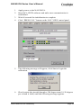
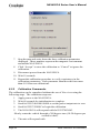


![CRM500GA-[] Installation Manual](http://vs1.manualzilla.com/store/data/006898720_1-f0e1190871b35d4edde661234bc5fb96-150x150.png)


![CRM500GA-[] Installation Manual](http://vs1.manualzilla.com/store/data/006898113_1-6a3403dda4ef0cbf7e311a8a73ef8735-150x150.png)