1
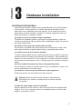
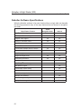
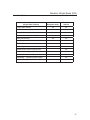
���
�������
���
���������
���
��������
�����������������������
�����������������
���
�������
���
��������
���������������������������������
Radar Installer’s Guide
���
������
Covers the Nobeltec Line of Radar Products
���
��
Nobeltec
InSight Radar 2 (IR2)
®
™
NTMRG003 2/05
Table of Contents
Introduction.................................................................... 1
Welcome to Nobeltec ..........................................................1
What is InSight Radar 2 (IR2)? ...........................................1
System Configurations ........................................................2
Minimum System Requirements ....................................2
Recommended System Requirements ..........................2
InSight Radar Sample Installations .....................................3
Installation at a Glance........................................................6
Getting Ready ................................................................ 7
Inspections of the delivered goods .....................................7
Part Numbers List ..........................................................7
Standard Equipment List ...............................................8
Optional Cable List ........................................................8
Checking the Power Supply ................................................9
Hardware Installation .................................................. 11
Installing the Radar Base ..................................................11
Shifting away from obstacles .......................................12
Installing the Antenna Unit ...........................................13
Installing the Antenna to the Base ....................................16
Installing the Control Box ..................................................17
Connecting the cables .......................................................18
Cable #1: Radar Cable - From Radar .........................19
Cable connections for OPEN scanner .........................22
Grounding the Antenna Unit ........................................24
Cable #1: Radar Cable - to Control Box ......................25
Cable #2: Power Supply Cable ....................................26
Cable #3: Power On/Off Switch ...................................28
Cable #4: Ethernet Connector Cable ...........................29
iii
Nobeltec InSight Radar (IR2)
Installer’s Guide
The PC Connection ..................................................... 31
Determining Desired Box Connection type .......................31
Installing Nobeltec Software ..............................................32
Connecting Options ...........................................................33
Option #1: Connecting IR2 directly to a PC.................33
Option #2: Connecting IR2 to an existing network ......34
Connecting IR2 directly to a PC ........................................36
Connecting IR2 to an existing network .............................38
Using the Radar Setup Wizard .........................................41
Initial Radar Setup .............................................................44
Setting the Trigger Delay .............................................44
Aligning the Radar Image ............................................45
Setting the Radar Presets ..........................................49
Product Specifications ............................................... 53
Radar Specifications .........................................................53
Nobeltec Software Specifications ......................................56
Dimensions and Weight ....................................................58
Troubleshooting .......................................................... 63
Troubleshooting Direct Connections .................................63
Troubleshooting Network Connections .............................64
Frequently Asked Questions .............................................67
iv
Nobeltec InSight Radar (IR2)
Installer’s Guide
Safety Instructions
Do not open the equipment unless familiar with electrical circuits and
the service manual.
Wear a safety belt and hard hat when working on the antenna unit.
Serious injury or death can result if someone falls from a radar mast.
Turn off all power before beginning installation.
Fire, electrical shock or serious injury can result if the power is left on or is
applied while the equipment is being installed.
Radio Frequency Radiation Hazard.
The radar antenna emits electromagnetic radio frequency (RF) energy which
can be harmful, particularly to your eyes. Never look directly into the antenna
from a close distance while the radar is in operation. Never expose yourself
to the transmitting antenna at a close distance.
LIMITED WARRANTY
Please read the enclosed warranty certificate for all warranty questions.
In brief: For customers inside the USA, Nobeltec and its hardware
providers offer a limited warranty of 2 years on parts and 1 year on labor
for all IR2 hardware. For all other customers, a 2 year limited warranty on
parts that are delivered from Nobeltec's hardware partner.
© Nobeltec Corporation 2005. All rights reserved.
Portions © 2004 Koden Electronics Co.,Ltd. All rights reserved.
No part of this publication may be reproduced, transmitted, translated in any form by any
means without the written permission of Nobeltec and/or Koden Electronics Co., Ltd.
The technical descriptions contained in this publication are subject to change without
notice. Neither Nobeltec nor KODEN assumes any responsibility for errors, incidentals or
consequential damages caused by misinterpretation of the descriptions contained in this
publication.
v
chapter
1
Introduction
Welcome to Nobeltec
Congratulations. You have purchased the worlds most advanced radar in the
recreational marine industry. This Installers Guide assumes that you are a qualified
marine electronics technician and are already familiar with Nobeltec’s charting
software and the process of installing sensitive electronic devices.
What is InSight Radar 2 (IR2)?
IR2 is Nobeltec’s radar solution. It includes a special radar that transmits digital data
through a converter box into a PC ready digital format. It also includes a special
version of Nobeltec’s navigation software designed to work with this digital radar
data stream. This radar software includes a host of powerful tools designed to make
navigating more safe and fun.
InSight Radar in the Nobeltec Admiral’s NavView interface.
1
Nobeltec InSight Radar (IR2)
Introduction
Installer’s Guide
System Configurations
IR2 communicates with a proprietary protocol through standard PC networking
devices. The Nobeltec line of products takes advantage of all the power of the PC
turning a standard or more ruggedized PC into the world’s most powerful navigation
platform.
Minimum System Requirements
-
Microsoft Windows 2000 or XP
-
1.0 GHz processor with 256 MB Ram
-
16 bit color VGA-compatible display or better
-
64 MB (or better) high-end video graphics card
-
25 MB hard disk space – (additional space required for charts or other data)
-
CD-ROM (DVD required for Passport Deluxe data)
-
Available Serial and/or USB ports for NMEA data
-
Mouse or other pointing device
-
GPS for positioning
-
10/100 Ethernet Card
Rapid output Heading Sensor (Use GPS Gyro Heading Sensor for best radar
overlay on electronic charts)
Recommended System Requirements
In order to get the best results using Nobeltec InSight Radar software, we
recommend you use a PC with the following specifications:
-
Windows 2000/XP Pro
-
Pentium IV 2.4 GHz with 512 MB RAM (or more) and 50 MB hard disk space
(Additional space required for navigation data)
-
CD and DVD-ROM drive
-
The following available data ports
•
2 Serial or USB ports (GPS, Heading sensor or other device)
•
USB port for Nobeltec InSight Radar Box input (if applicable)
•
Ethernet Network port for the Digital Radar input (if applicable)
-
High-end 3D video graphics card with OpenGL capabilities
-
Heading Sensor capable of outputting NMEA heading information If not using
the preferred combo GPS/Heading sensor, we recommend the Nobeltec heading
sensor. Its fast 10Hz output makes for better radar overlay.
-
GPS capable of outputting NMEA position information within 6’ accuracy or a
GPS Gyro heading sensor.
2
Nobeltec InSight Radar (IR2)
Installer’s Guide
Introduction
InSight Radar Sample Installations
IR2 with Single Computer
Note: Dashed Boxes indicate user supplied options
Notes for this system:
-
System must have either a combo GPS heading sensor or a separate digital
compass.
-
Requires the PC to have a static IP address of 192.168.0.100 (or any other
compatible IP address) for InSight Radar connection.
-
Number of NMEA inputs is 32 but if not setup properly can overwhelm the PC
Communication ports.
-
GPS Gyro Heading sensor provides best results for Radar / Chart overlay.
-
For differences between VNS and Admiral, see Chapter titled: Specifications.
3
Nobeltec InSight Radar (IR2)
Introduction
Installer’s Guide
IR2 to a Nobeltec GlassBridge™ Network
Notes for this system:
-
System must have either a combo GPS heading sensor or a separate digital
compass.
-
Requires approved Ethernet router/hub for proper InSight Radar operation.
-
IP Addresses are established dynamically by router for InSight Radar connection.
-
Secondary laptop can be wired or wireless (provided that a wireless router/hub
exists operating at 802.11g or higher).
-
Wireless Nobeltec Display essentially repeats anything displayed on primary nav
system including Radar. (Requires a separate network connection on the PC
from the radar.)
-
Maximum of seven (7) monitors per PC.
-
Nobeltec’s GlassBridge Network broadcasts NMEA data to all copies of Admiral
on the network.
-
GPS Gyro Heading sensor provides best results for Radar / Chart overlay.
4
Nobeltec InSight Radar (IR2)
Installer’s Guide
Introduction
Dual IR2’s to a Nobeltec GlassBridge™ Network
Notes for this system:
-
Same as single radar on network (prior page)
-
Each computer can only work with one IR2 at a time. To switch radars requires
the user ro re-setup the radar using the Radar Setup Wizard.
5
Nobeltec InSight Radar (IR2)
Installer’s Guide
Installation at a Glance
Below are the major steps for installing the Nobeltec InSight Radar solution. Use this as a
guide for the installation process.
Step 1. Verify that you have everything.
(Installers Guide – Chapter 1)
Step 2. Install the radar and Control Box.
(Installers Guide – Chapter 2)
Step 3. Install Nobeltec software and configure IP address.
(Installers Guide – Chapter 3)
Step 4. Run the Radar Setup Wizard.
(Installers Guide – Chapter 3)
Step 5. Final Radar Setup
(Installers Guide – Chapter 3)
Step 6. Orient yourself and the customer to Nobeltec software and
radar.
(Operations Manual)
6
chapter
2
Getting Ready
This chapter describes the IR2 components in preparation for installing on the
vessel as well as some necessary precautions to be observed. The following
diagram explains in more detail about the order of the system installation.
Inspections of the delivered goods
Unpack your package and check if all of the following items are included and in
good order.
Part Numbers List
Group
Name
IR2-4D
Product
Name
IR2-4D
Radar
Base
RB715A
IR2-4.3
IR2-4x
RB716A
IR2-4.4
IR2-6.4
IR2-6x
RB717A
IR2-6.6
IR2-12.4
IR2-12x
RB718A
IR2-12.6
IR2-25.4
IR2-25x
IR2-25.6
IR2-25.9
RB719A
Antenna
Part #
Power
N/A
(4 kW)
RW701A-03
(4 kW)
RW701A-04
(4 kW)
RW701A-04
(6 kW)
RW701A-06
(6 kW)
RW701A-04
(12 kW)
RW701A-06
(12 kW)
RW701A-04
(25 kW)
RW701A-06
(25 kW)
RW701B-09
(25 kW)
Antenna
Type
Size
Antenna
Cable #
Length
Dome
25” / 2.1’
Open Array
41” / 3.5’
Open Array
53” / 4.5’
Open Array
53” / 4.5’
Open Array
78” / 6.5’
Open Array
53” / 4.5’
Open Array
78” / 6.5’
Open Array
53” / 4.5’
Open Array
78” / 6.5’
Open Array
108” / 9.0’
242J158055A
10 meter
242J159098A
10 meter
242J159098A
10 meter
242J159098A
10 meter
242J159098A
10 meter
242J159098A
10 meter
242J159098A
10 meter
242J159098A
10 meter
242J159098A
10 meter
242J159098A
10 meter
Radar
Control
Box
MDS-5R
MDS-6R
7
Nobeltec InSight Radar (IR2)
Getting Ready
Installer’s Guide
Standard Equipment List
IR2-4D
IR2-4x
IR2-6.x
Q’ty
Q’ty
Q’ty
Q’ty
Q’ty
Antenna unit (RB715A)
1
NA
NA
NA
NA
Antenna unit (RB716A)
NA
1
NA
NA
NA
Antenna unit (RB717A)
NA
NA
1
NA
NA
Antenna unit (RB718A)
NA
NA
NA
1
NA
Antenna unit (RB719A)
NA
NA
NA
NA
1
1 (10m)
1 (10m)
1 (10m)
1 (10m)
1 (10m)
Nobeltec Part No. *
Items
Interconnecting cable
M12 hexagonal bolt (M10 bolts
for Dome models)
IR2-12x IR2-25x
4 sets
Control box (MDS-5R)
1
NA
Control box (MDS-6R)
NA
1
Power supply cable (2m)
1
Tapping screw
4
Fuse
4
LAN data cable(Crossover) (2m)
1
Switch
1
Quick Start Guide
1
Installers Guide
1
Operations Manual
1
Optional Cable List
IR2-4x
8
IR2-6x
Cable length
IR2-4D
10 meter (standard)
242J158055A
IR2-25x
242J159098A
15 meter
242J158055B
242J159098B
20 meter
242J158055C
242J159098C
30 meter
242J158055D
242J159098D
IR2-12x
Nobeltec InSight Radar (IR2)
Installer’s Guide
Getting Ready
Checking the Power Supply
To allow proper operation of the IR2 radars, the ship’s power supply capacity must
satisfy the requirements detailed in the following table. Keep the battery properly
charged anytime to prevent it from discharging.
Power Supply Requirements
Supply voltage used
Maximum current drain
Allowable voltage range
12 VDC
5A (IR2-4D)
6A(IR2-4x)
7A (IR2-6x)
8A(IR2-12x)
10.2 to 41.6V
24 VDC
(required for double speed
support in Nobeltec Admiral)
2.5A (IR2-4D)
3A(IR2-4x)
3.5A (IR2-6x)
4A(IR-12x)
5.4A (IR2-25x)
18.6 to 41.6V
CAUTION: AC power supply cannot be used
Fuse Replacement
Properly rated fuses must be used for a safe and proper operation of the IR2 radar
sensor unit. Refer to the following tables for correct ratings of the fuses used in the
respective models.
Supply Voltage to Fuse Table for IR2-4D
Supply voltage used
Main Fuse
Motor Fuse
12 VDC
10A/250V or 125V
*(6.3Ø x 32mm)
T3.15A/250V or 125V
*(5Ø x 20mm)
24 VDC
10A/250V or 125V
(6.3 Ø x 32mm)
T3.15A/250V or 125V
(5Ø x 20mm)
Note: Marked * fuses are included with IR2.
9
Nobeltec InSight Radar (IR2)
Getting Ready
Installer’s Guide
Supply Voltage to Fuse Table for IR2-4x, IR2-6x and IR2-12x
Supply voltage used
Main Fuse
Motor Fuse
12 VDC
10A/250V or 125V
(6.3Ø x 32mm)
5A/250V or 125V
(5Ø x 20mm)
24 VDC
10A/250V or 125V
*(6.3 Ø x 32mm)
T3.15A/250V or 125V
*(5Ø x 20mm)
Note: Marked * fuses are included with IR2.
Supply Voltage to Fuse Table for IR2-25x
Supply voltage used
Main Fuse
Motor Fuse
24 VDC
10A/250V or 125V
*(6.3 Ø x 32mm)
5A/250V or 125V
(5Ø x 20mm)
T3.15A/250V or 125V
*(5Ø x 20mm)
Note: Marked * fuses are included with IR2
10
chapter
3
Hardware Installation
Installing the Radar Base
A radar's target detection capacity varies greatly depending on the fitted position
of the scanner. An ideal position is a location high above the ship's keel line
where there are no obstacles around the scanner. On an actual ship, such an
ideal location is limited, therefore, consider the following suggestions when you
determine the place to install the scanner:
(a) Install scanner at a position as high as possible.
The higher the installation position, the longer the ranging distance. Install the
scanner at a position as high as possible after considering the ship's hull structure
and radar maintainability.
(b) Install scanner away from smoke-stack and mast
If the scanner is installed at the same height as the smoke-stack or mast, radar
waves may be blocked, creating shadow zones or generating false echoes.
(c) Install scanner as far forward as possible.
To avoid creating shadow zones or generating false echoes, install the scanner at
a position nearer to the ship's bow and away from obstacles. When installing the
scanner on a mast, position it in front of the mast (If obstacles cannot be avoided
for the ship's structural reasons, refer to "Shifting away from obstacles" described
below.)
(d) Do not install the scanner near hot or heat-generating items.
Do not install the scanner at a position where it may be subjected to smoke or hot
air from smokestacks or heat from lamps.
(e) Install the scanner away from antennas of other equipment.
Install the scanner as far as possible from radio antennas.
Warning: Radar can effect and be effected by other antennas.
Ensure that your scanner is installed as far from other antennas
as possible.
(f) Make the cable length as short as possible.
Keep the distance from the scanner to the control box within the standard cable
length of 10 m. If you use longer cable for unavoidable reasons, limit the cable
length to a maximum of 100 m.
11
Nobeltec InSight Radar (IR2)
Hardware Installation
Installer’s Guide
Shifting away from obstacles
Shifting from keel line
By shifting the scanner position from the keel line to the starboard side of the ship,
it is possible to move shadow zones to the port side which can keep a clearer
vision in the bow direction. The starboard shift distance is obtained by a few
measurements and using the calculation below.
Ls=0.4R+D/2 [m]
(when R<15m)
Ls=0.025R+D/2 [m]
(when R>=15m)
Where:
Ls = Length of shift or distance to be shifted from keel line
D = diameter of obstacle on keel line
R = distance from scanner to obstacle
Figure 2.1: Shifting the antenna from keel line
Obtaining sufficient dip angle
Raise the scanner position so that there is a sufficient dip angle (available between
the line of sight from the scanner to the obstacle and the horizontal line.) By raising
the dip angle above 5 degrees, it is possible to prevent mid- and long-distance
shadow zones. The radar cannot detect objects below the line of sight.
Figure 2.2: Obtaining sufficient dip angle
12
Nobeltec InSight Radar (IR2)
Installer’s Guide
Hardware Installation
Installing the Antenna Unit
When you have decided the place of installation, prepare the mounting bracket or
platform as shown in Figure 2.3. If the surface of a platform or mounting base is
not even, insert appropriate fairing materials between the antenna pedestal and the
mounting surface to ensure a stable mounting platform.
Figure 2.3: Recommended mounting base or platform
Using the included drill-hole template (or you can refer to the drawings in Figure
2.4), drill holes for the five locations on the mount base and use these holes to fix
the scanner unit to the mount base with hexagonal bolts. The bolts included with
your radar equipment will suffice for mount base thickness of 9 to 14 mm (0.35 to
0.55 in.). If the mount base is thicker or thinner than this, prepare the bolts listed in
the tables 2.1 and 2.2.
Mounting diagram for
IR2-4x, 6x, 12x, 25x
Mounting diagram for
IR2-4D
Figure 2.4: Mounting diagrams
Note: Access hole for vertical cable entry only.
13
Nobeltec InSight Radar (IR2)
Hardware Installation
Installer’s Guide
Figure 2.5: Dome fixing details
Figure 2.6: Open Antenna fixing details
Use sealing of silicon to prevent the bolts from becoming loose. Radome may be
broken if you use locking putty.
14
Nobeltec InSight Radar (IR2)
Installer’s Guide
Hardware Installation
Table 2-1 Bolts for Mounting Scanner Unit (Radome antenna)
Thickness of mount
base
Bolts necessary to fix radome
scanner
Material
1-4mm(0.04-0.16 in.)
M10 × 15 (1.5mm pitch)
Stainless
4-9mm(0.16-0.35 in.)
M10 × 20 (1.5mm pitch)
Stainless
9-14mm(0.35-0.55 in.)
M10 × 25 (1.5mm pitch)
Stainless
14-19mm(0.55-0.75 in.)
M10 × 30 (1.5mm pitch)
Stainless
Remarks
Included
Table 2-2 Bolts for Mounting Scanner Unit (Open antenna)
Thickness of mount
base
Bolts necessary to fix radome
scanner
Material
1-4mm(0.04-0.16 in.)
M12 × 45 (1.5mm pitch)
Stainless
4-9mm(0.16-0.35 in.)
M12 × 50 (1.5mm pitch)
Stainless
9-14mm(0.35-0.55 in.)
M12 × 55 (1.5mm pitch)
Stainless
14-19mm(0.55-0.75 in.)
M12 × 60 (1.5mm pitch)
Stainless
Remarks
Included
15
Nobeltec InSight Radar (IR2)
Hardware Installation
Installer’s Guide
Installing the Antenna to the Base
Remove the protective cap covering the rotary coupler on the top of the scanner.
Match the antenna radiation direction to the direction of the arrow markings on the
rotation base and secure the antenna in position using four M8 bolts.
Figure 2.7 Fitting the Aerial Unit
16
Nobeltec InSight Radar (IR2)
Installer’s Guide
Hardware Installation
Installing the Control Box
After you have finished installing the scanner unit, install the Control Box in the
same way.
Find a dry weather and waterproof place within reach of the Antenna cable. Choose
a proper bolt length according to the thickness of the surface on which you are
going to install the Control Box. The hole diameter is different when using bolts or
tapping screws. When using tapping screws, drill holes in a matched size. When
using bolts and nuts, drill the holes of 6 mm (0.24 in.) diameter. When you have
finished, install the pedestal part first and then the control box.
Figure 2.8 Dimensions of the fixing hole positions
17
Nobeltec InSight Radar (IR2)
Hardware Installation
Installer’s Guide
Connecting the cables
There are four cables that need to be connected.
Figure 2.9: General cabling diagram
General considerations
The cable connecting the Antenna and Control unit should already be attached to
the Antenna. By default these cables come in 10 meter lengths, however longer
cables are available and are typically installed at the factory. However, should the
need arise for you to replace the cable, use this section to understand how this
occurs. If the desired cable is attached to the antenna, you can skip this entire
section.
1) The cable connecting the Antenna and Control Unit should be run separately
away from other cables such as, radio antenna feeders, power cables, etc.
Under no circumstances should it be in parallel arrangement with other cables.
These precautions are essential to avoid radio interference to/from other equipment installed on the ship. If this is not possible, either cable set should be
screened with metal conduit or another form of shielding.
2) Cable should be run as short as possible but be kept within the standard length
to achieve best radar performance.
3) The copper braids of the cable must be grounded via a grounding stud in the
transceiver unit.
18
Nobeltec InSight Radar (IR2)
Installer’s Guide
Hardware Installation
Cable #1: Radar Cable - From Radar
The first cable is the one that connects the radar scanner to the Radar Control Box
(MDS-5R or MDS-6R). If this cable is already attached to the Radar Base you can
skip this section.
Remember: This side of Cable #1 is normally supplied already
connected with 2kW models. All other radar models should follow
the instruction listed below.
Connections with IR2-4D (RB715A)
1) Remove the radome cover from the Antenna unit by gently lifting upward to avoid
bumping against the internal aerial. (There are four screws holding it in place.)
2) If necessary, remove the tape securing the antenna.
3) Remove the shield cover located on the backside.
4) Remove the cable clamping plate and rubber ring, pass the cable through
the opening, replace the rubber ring, and clamp the cable to the scanner unit
with screws on the fixing plate. Attach the cable connector to the X1 and X2
connectors on the printed circuit board.
5) Replace the aluminum cover. Lay the cable shield into the channel machined into
the aluminum housing. Be careful that the cable will not get caught between the
main unit and cover.
6) Manually rotate the antenna to ensure that radar wand will not bump up against
or hit the cable.
7) Replace the upper part of the radome, being careful not to bump it against the
antenna. Make sure that the cover is positioned in the correct direction as shown
in Figure 2.10. The upper and lower parts of the radome each have alignment
markings indicating screw positions.
19
Nobeltec InSight Radar (IR2)
Hardware Installation
20
Installer’s Guide
Nobeltec InSight Radar (IR2)
Installer’s Guide
Hardware Installation
Figure 2.10 Fitting the cover (Radome antenna)
Figure 2.11: Fitting the Radar Cable to the IR2-4D radome
21
Nobeltec InSight Radar (IR2)
Hardware Installation
Installer’s Guide
Cable connections for OPEN scanner
1) Use a socket wrench to remove the back cover of the scanner unit.
2) Remove the two bolts securing the transceiver.
3) Remove the connectors to the motor (X1: RB716A, J5:RB717A/718A/719A) and
to the heading switch (X2: RB716A, J3: RB717A/718A/719A ). Pull out the transceiver.
4) Remove the four bolts securing the fixing plate at the cable entrance.
5) Remove the metal fixing plate, rubber seal and the washer that secure the cable.
Pass the cable through as shown in the diagram below; replace the above items
and tighten the bolts.
6) Return the transceiver to its original position and secure it with the bolts
removed.
7) Connect the 7-pin connector to X11 (RB716A)/J2 (RB717A/718A/719A ) and the
9-pin connector to X12 (RB716A)/J1 (RB717A/718A/719A) of the printed circuit
board and connect the two connectors removed in Step 3.
8) Replace the scanner cover. Take care the cover does not pinch the cable when
reattaching the cover.
22
Nobeltec InSight Radar (IR2)
Installer’s Guide
Hardware Installation
Figure 2.12 Fitting interconnecting cable (Open scanner)
23
Nobeltec InSight Radar (IR2)
Hardware Installation
Installer’s Guide
Grounding the Antenna Unit
Connect a grounding wire from one of the bolts on the scanner base as shown in Figure 2.13.
(The crimping terminal and grounding wire are user-supplied items.)
Figure 2.13 Grounding the Antenna Unit
24
Nobeltec InSight Radar (IR2)
Installer’s Guide
Hardware Installation
Cable #1: Radar Cable - to Control Box
The other end of Cable #1 is connected to the Control Box. Simply plug the cable
into the appropriate port on the top of the Control Box.
Cable #1: Radar Connector Cable
Radar side
Control Box side
IR2-4D: SCAN-RMD PCB X11
Radar Control Box
IR2-4x, 6x, 12x: SCAN-OPN
PCB X11
Radar Connector
No
Color
Function
1
17 Violet
+250V
2
N/A
3
17 Yellow
Ground
4
34 Red
Ship’s +
5
34 Yellow
Ship’s +
6
34 Green
Ship’s -
7
34 Blue
Ship’s -
IR2-4D: SCAN-RMD PCB X12
No
Function
No
Function
1
+250V
9
BP/SHF-R
2
+24V
10
V/TRG
3
+12V
11
N/A
4
Ground
12
SHIP’S +
5
DAT-R
13
SHIP’S +
6
DAT
14
V/TRG-R
7
N/A
15
SHIP’S -
8
BP/SHF
16
SHIP’S -
IR2-4x, 6x, 12x, 25x: SCANOPN PCB X12
No
Color
Function
1
17 Blue
+24V
2
N/A
3
34 Orange
+12V
4
Braid of Red
DAT-R
5
Red
DAT
6
Braid of
Brown
BP/SHF-R
7
Brown
BP/HG
8
Braid of
Gray
V/TRG-R
9
Gray
V/TRG
Figure 2.14 Cable #1 Wiring and connector pinouts.
25
Nobeltec InSight Radar (IR2)
Hardware Installation
Installer’s Guide
Cable #2: Power Supply Cable
Cable #2: Power Supply
Connector Pinouts
No
Color
Function
1
Black
DC-
2
White
DC+
3
N/A
N/A
4
N/A
N/A
5
Grey
Ground
Power should be fed through a switch and protective fuses (or circuit breakers), as
shown below.
Figure 2.15 Typical power supply switch wiring.
Warning: Do not apply over 41.6V to the Control Box or it may be
damaged beyond repair! See the power table below to ensure the
correct power supply
26
Nobeltec InSight Radar (IR2)
Installer’s Guide
Hardware Installation
Power Supply Requirements
Supply voltage used
Maximum current drain
Allowable voltage range
12 VDC
5A (IR2-4D)
6A(IR2-4x)
7A (IR2-6x)
8A(IR2-12x)
10.2 to 41.6V
24 VDC
(required for double speed
support in Nobeltec Admiral)
2.5A (IR2-4D)
3A(IR2-4x)
3.5A (IR2-6x)
4A(IR-12x)
5.4A (IR2-25x)
18.6 to 41.6V
CAUTION: AC power supply cannot be used
Plug the included power supply cable into the connector on the Control Box labeled
“Power”. Make sure to place the fuse and connector in a dry splash-free area. When
extending the cable, use a suitable cable as indicated below.
Supply voltage used
12 VDC
24 VDC
Cable Conductor
Cable Max Length
12 Gauge
25 Feet
10 Gauge
60 Feet
12 Gauge
70 Feet
10 Gauge
120 Feet
Figure 2.16 Cable #2: Power supply cable.
27
Nobeltec InSight Radar (IR2)
Hardware Installation
Installer’s Guide
Cable #3: Power On/Off Switch
Cable #3: Power
On / Off Connector
Pinouts
No
Function
1
Power +
2
N/A
3
N/A
4
Power -
You may use the On/Off switch provided or another style if desired. If you choose
to use a different style, it must be rated for 30 VDC or more and have a carrying
capacity of .1A or higher.
The On/Off switch does not carry the main power to the Control Box. To install the
On/Off switch, follow these steps.
1) Once you have identified an optimal location for the On/Off switch that is readily
accessible, route the blue and green wires to this location.
2) Refer to the diagram below to layout and cut a rectangular mounting hole for the
switch.
3) Pass the the green and blue wires through the hole from behind the panel and
connect the wires to the switch.
4) Press the switch into the mounting hole.
5) Place the On/Off switch into the Off position.
Figure 2.17 Cable #3: Power On / Off switch.
28
Nobeltec InSight Radar (IR2)
Installer’s Guide
Hardware Installation
Cable #4: Ethernet Connector Cable
Cable #4: Ethernet Cable
From Control Box to PC
No
Function
1
RD+
2
RD-
3
TD+
4
Termination
5
Termination
6
TD-
7
Termination
8
Termination
9
Ground 1
10
Ground 1
Figure 2.18 Cable #4: Control Box rear view.
The Ethernet connector cable is discussed in greater length in the next chapter.
Changing the Dip Switch Settings
The dip switch settings are set at the factory and should not need to be changed.
However, changing the dip-switches may be necessary to optimize and/or customize
an installation. For example, on a direct connect installation, you may turn S11 off to disable the DHCP client. Changing this eliminates the one-minute delay
before the radar is available due to DHCP activity. Additionally, you may need to
change the default IP address of the radar to prevent conflict with other devices in a
network. Please contact Nobeltec before changing these settings.
Record any changes made to the switches in the column labeled New Value below.
Warning: Electronic circuits and memories are sensitive to static
shock. Make sure that you are grounded to a static pad before
opening the box and making any changes.
29
Nobeltec InSight Radar (IR2)
Installer’s Guide
Dip switches are located inside of the IR2 interface box. Disconnect all cables and
remove the screws on the side of the box and lift off the lid to get access to the
switches. Record all switch values before making any changes. Also, make sure not
to touch any of the circuit boards.
Dip Switch
S1-1
New Value
Meaning
On = DHCP Client On
Off = DHCP Client Off (always use encoded IP address)
These switches changes the IP address of the box from
the default value. (Make sure S1-8 is On)
S1-2 to S1-6
S1-8
30
Value
S1-2
S1-3
S1-4
S1-5
S1-6
Offset
+ 0 (Default)
Off
Off
Off
Off
Off
00000
+1
Off
Off
Off
Off
On
00001
+2
Off
Off
Off
On
Off
00010
+6
Off
Off
On
On
Off
00110
+ 30
On
On
On
On
Off
11110
+31
On
On
On
On
On
11111
On = Default IP and Mac Address
Off = Enable Custom IP Address
chapter
4
The PC Connection
Determining Desired Box Connection type
The IR2 Radar connects to the PC through the Control Box using an Ethernet type
connection. The PC must have a network interface card (NIC) which looks like
an oversized phone connector (RJ-45) on the back of most laptops and desktop
computers. Ethernet networks are standard in the PC industry and supplies such as
cabling, routers and Network Interface Cards (NIC) are widely available.
There is a list of terms that will help make sense of the connection process:
IP Address
Internet Protocol host address usually represented in dotted
decimal notation. The IR2 has a default IP address when not
connected to router/hub of 192.168.0.1. When connected
through a router/hub, the IP address is assigned by that router/
hub (which acts as a DHCP server).
MAC Address
Media Access Control is the HW address of a device.
DHCP Server
Dynamic Host Configuration Protocol is a protocol for
automating and facilitating the communication of computers
that use TCP/IP. Any network running with IR2 must have a
DHCP server (typically served by the router/hub.)
Router/ Hub
A device which forwards data packets between networks or
devices within a network. Router/hubs that work with IR2 must
be setup as a DHCP server. Some Router/hubs can also send
data over a wireless protocol called 802.11g (or faster).
Ethernet
A type of networking technology for local area networks.
NIC
Network Interface Card. This device contains an Ethernet port
and are most typically built onto the PC motherboard.
Patch Cable
An Ethernet male to male cable intended to connect devices
to a network hub/router. In a PC network with a router, patch
cables are likely the only cable used. Patch cables are not
included with the IR2 but are available at any electronics store.
Cross-over Cable An Ethernet male to male cable used to connect devices
directly to a PC. A crossover cable is included with the IR2.
TCP/IP
Transmission Control Protocol/Internet Protocol is a set of
communication protocols developed for the Internet in the
1970’s by the US DoD to get data from one network device to
another and is widely used for PC network connections.
As a summary to the terms above:
The IR2 Radar is either assigned an IP address or if necessary uses its default
IP address to communicate via TCP/IP over an Ethernet network. Facilitating
this communication might be a router or hub which allows greater flexibility and
expansion within the network.
31
Nobeltec InSight Radar (IR2)
The PC Connection
Installer’s Guide
Installing Nobeltec Software
It is necessary to install this software even if you have Nobeltec software already
loaded on your system. In addition to installing the Nobeltec software on a new
computer, it can also upgrade existing Nobeltec software to recognize, and operate
the InSight Radar 2.
To install the Nobeltec software, Insert the program CD into your CD-ROM drive.
The program will autorun an installation program.
Follow the on screen instructions to install or update the Nobeltec software.
If the CD does not autorun, follow the next set of instructions.
1) Select Start | Run from the taskbar and type D:\setup.exe (substitute the drive
letter of your CD-ROM drive for “D” if it is different).
2) Follow the on screen instructions to install or update the Nobeltec Software.
Once installed, you should see a splash screen similar to the one shown below.
Nobeltec Admiral’s Splash Screen showing
the InSight Radar components are installed.
Tip: Notice that in the lower right corner, under the banner:
“Including”, the InSight Radar components are installed. If you do
not see this, chances are good that you have installed the wrong
CD. Locate the correct CD and re-install.
32
Nobeltec InSight Radar (IR2)
Installer’s Guide
The PC Connection
Connecting Options
There are essentially two ways to connect the IR2 Radar to the PC. After evaluating
each type, choose the system setup that best fits your needs and go to the section
that describes its setup.
Option #1: Connecting IR2 directly to a PC
This option is for systems that do not have a network hub or router and is generally
used when there is only one PC on the boat to which the IR2 radar is going to be
connected. If you have an onboard network, you can also direct connect the IR2 to
a PC if the PC has a second network interface card (NIC). This option requires that
the PC has a specific IP address that is compatible with the Control box default IP
address.
Figure 3.1 InSight Radar connected directly to PC
33
Nobeltec InSight Radar (IR2)
The PC Connection
Installer’s Guide
Option #2: Connecting IR2 to an existing network
The second option for connecting the IR2 radar to a PC is through an existing
network hub or router. With this solution, you should already have a network setup
and operating that has a router or hub acting as a DHCP server to the PC’s and
other connected devices.
34
Nobeltec InSight Radar (IR2)
Installer’s Guide
The PC Connection
CAUTION
The amount of non-radar network traffic can dramatically reduce the
quality of the radar presentation. This is particularly true if using a
wireless network or when using the network for high-bandwidth uses
such as browsing the Internet or sharing files.
CAUTION
PC network installations can be significantly more complicated. Make
sure to verify that the network is properly setup and running, and
that a qualified network administrator is on-board. Other than limited
phone support, Nobeltec is not able to provide support on Network
installation or operation.
CAUTION
Wireless networks function with limited bandwidth and are susceptible
to RF interference. Please check with Nobeltec for tested network
components.
How does the IR2 Control Box know what IP address to use?
When powered on, the IR2 Control Box attempts to communicate to the network to
request an IP address. If a router or hub or other DHCP serving device responds
with an IP address, then the IR2 Control Box knows it is on a network and operates
with the assigned IP address. It is then available by all copies of Nobeltec Admiral
on the network. If after a short time no IP address is given, then the IR2 Control box
defaults to its backup IP address which is 192.168.0.1. Resetting the IP address on
the Control box only happens if the power is recycled on the control box.
35
Nobeltec InSight Radar (IR2)
The PC Connection
Installer’s Guide
Connecting IR2 directly to a PC
If you have chosen to connect the radar directly to the PC, the cable supplied
with the radar is the correct cable. However, since Windows is not setup from the
manufacturer to operate a network without a hub, there are a few steps to follow.
Step 1: Connecting the devices
Using the included Crossover cable connect the Control Box to the PC. Plug either
end into the control box and PC (cable direction is not important.) If the enclosed
cable is too short, you can purchase longer cables (For direct connects – make
sure that you purchase a crossover cable.) The cable should be as short as
possible, but can be up to 200’ if required.
Step 2: Configure your PC to talk directly to the Control box
Windows assumes the existence of a router/hub and is pre-configured to obtain an
IP address automatically. In this case, no such device exists, so the IP address on
the PC needs to change for compatibility with the IR2 Control box.
1) Open the Windows Control Panel. This is typically accomplished by clicking
on the Start button, then on Control Panel (Older versions of Windows, may
require that you click on the Start button, then on Settings and then on the
Control Panel option).
2) Once in the Control Panel, double click on the Network Connections icon
(older versions of Windows call this by a slightly different name. It will be named
similar to "Network and Dial-up connections").
Network Connections window. Because PC’s can
connect to more than one network, you may see more
than one Local Area Connection icon.
36
Nobeltec InSight Radar (IR2)
Installer’s Guide
The PC Connection
3) Open the Internet Protocol (TCP/IP) Properties window, by double clicking on
the Network icon that is going to be used to connect to the IR2
This opens the Connection Status window (below left), now click on the
Properties button to open the Connection Properties window (below middle).
Now click on the Internet Protocol (TCP/IP) item in the list and then on the
Properties button as shown. This final step opens the Internet Protocol (TCP/
IP) Properties window (below right).
Connection Status
Window
Connection Properties
Window
TCP/ IP Properties
Window
4) Once in the TCP/IP Properties window, click on the option labeled Use the following IP address. Then In the address field, type the following information:
IP Address
192.168.0.100
Subnet mask
255.255.255.0
Tip: In the event that your computer already has a local
connection with the IP address listed above, change the last 3
digits of the IP address from 100 to any number between 002
and 099.
Once this data has been entered, hit the OK button to close all the screens. You
may have to reboot the computer for the changes to take effect.
Once you’ve verified that the IP settings are correct, go to the Step titled: Using the
Radar Setup Wizard.
37
Nobeltec InSight Radar (IR2)
The PC Connection
Installer’s Guide
Connecting IR2 to an existing network
All computers running Windows assumes the existence of a router/hub and is preconfigured to obtain an IP address automatically. So, unless you have changed this
setting or you followed the instructions above for a direct connection, this setup
process is fairly straightforward.
Step 1: Connecting the devices
Using a patch cable (sold separately), connect the PC and the Control Box to an
appropriate Router/hub. If you are using a high speed wireless card, follow the
manufacturer’s installation procedures to get everything connected and tested
properly.
Patch cables should be as short as possible, but can be up to 200’ if required and
can be purchased from any computer supply store.
CAUTION
PC network installations can be significantly more complicated. Make
sure to verify that the network is properly setup and running, and
that a qualified network administrator is on-board. Other than limited
phone support, Nobeltec is not able to provide support on Network
installation or operation.
CAUTION
Wireless networks function with limited bandwidth and are susceptible
to RF interference. Please check with Nobeltec for tested network
components.
38
Nobeltec InSight Radar (IR2)
Installer’s Guide
The PC Connection
Step 2: Configure your PC to talk to the router/hub
IMPORTANT NOTE: If you already have a network running and the PC with
Nobeltec software is currently operating on this network, you can skip this step and
go straight to the section titled: Using the Radar Setup Wizard.
As mentioned above, Windows is normally set up to obtain its IP address
automatically. However, if you followed the Direct Connect instructions above, you’ll
need to reset this functionality by essentially reversing what we did above.
1) Open the Windows Control Panel. This is typically accomplished by clicking
on the Start button, then on Control Panel. Older versions of Windows, may
require that you click on the Start button, then on Settings and then on the
Control Panel option.
2) Once in the Control Panel, double click on the Network Connections icon.
Again, older versions of Windows call this by a slightly different name. It will be
named similar to "Network and Dial-up connections".
Network Connections window. Because PC’s can
connect to more than one network, you may see more
than one Local Area Connection icon.
39
Nobeltec InSight Radar (IR2)
The PC Connection
Installer’s Guide
3) Open the Internet Protocol (TCP/IP) Properties window, by double clicking on
the Network icon that is going to be used to connect to the IR2 (because PC’s
can connect to more than one network, you may see more than one Local Area
Connection icon than in the image above).
This opens the Connection Status window (below left), now click on the
Properties button to open the Connection Properties window (below middle).
Now click on the Internet Protocol (TCP/IP) item in the list and then on the
Properties button – as shown. This final step opens the Internet Protocol (TCP/
IP) Properties window (below right).
Connection Status
Window
Connection Properties
Window
TCP/ IP Properties
Window
4) Once in the TCP/IP Properties window, click on the option labeled Obtain an IP
address automatically. As in the image above right.
Once entered, hit the OK button to close all the screens. You may have to reboot
the computer for the changes to take effect.
40
Nobeltec InSight Radar (IR2)
Installer’s Guide
The PC Connection
Using the Radar Setup Wizard
This section assumes that you have correctly installed the IR2 and that it is
functioning properly.
The Insight Radar option to the Nobeltec software includes a Radar Setup Wizard
that simplifies the integration process. You must run the Radar Setup Wizard the
first time you install the software on a new computer on which you want to see the
InSight Radar.
The Wizard also sets up the communication ports for other NMEA devices such as
a GPS, heading sensor and more.
IMPORTANT NOTE FOR NETWORKS
When connecting multiple IR2 radars to the same network, you must
turn off all IR2 radars and copies of Nobeltec software connected to that
network except the IR2 radar with which you want to connect. Because,
Nobeltec Admiral can only work with a single radar at a time, multiple
radars on the same network require multiple copies of Admiral.
To launch the Radar Setup Wizard
1) Click on the Start button on your Windows task bar. Then Programs | Nobeltec |
Radar Wizard
If the Radar Setup Wizard is not in the Nobeltec program group you have not
installed the Nobeltec software with the Insight Radar module. Check to make
sure that you installed the correct CD.
2) After the opening screen appears, click on the Next button.
41
Nobeltec InSight Radar (IR2)
The PC Connection
Installer’s Guide
3) Verify that you have accomplished all of the requirements as outlined and then
click on the Next button.
The Radar Setup Wizard will search your available serial ports for incoming
information, including your GPS and heading sensor. Continue stepping through the
Radar Setup Wizard making sure to closely follow the instructions.
Tip: When you run the Radar Setup Wizard make sure that your
GPS, heading sensor and the radar are all properly installed,
42
Nobeltec InSight Radar (IR2)
Installer’s Guide
The PC Connection
turned on and connected to your computer.
Once the Radar Setup Wizard detects your radar and other NMEA devices you can
advance the Radar Wizard to the Adjust Radar Image page.
The primary objective on this page is to see the data in the white box towards the
bottom of this screen flowing on both sides. The data on the left side is data going
to the radar from the PC. The data on the right side is the radar responding to the
PC. As long as you see data on both sides of this window, you can finish the radar
wizard.
This page shows, after the appropriate radar warmup period of two minutes, a miniversion of the current radar image.
Tip: You may need to cycle the power on your radar for the
Radar Viewer image to appear.
If desired you can adjust the radar image inside the Radar Wizard. To do so, click
43
Nobeltec InSight Radar (IR2)
The PC Connection
Installer’s Guide
on the Adjust button to control various functions of the radar. None of the settings
that you enter here will be saved in the Nobeltec program.
Initial Radar Setup
Setting the Trigger Delay
After successfully installing the radar, the transmit trigger delay should be reviewed
and adjusted in order to compensate for cable transmission delays. Longer cable
runs, generally require a higher trigger delay setting.
To do so, Start the Nobeltec charting software and launch the Insight Radar window.
Once it is open and displaying a radar image, adjust the Transmit Trigger Delay. To
do this, click on the Radar drop down menu then on the Initial Radar Setup option.
Setting the Transmit Trigger Delay: The transmit trigger delay (TxTrig) is a setting,
when set incorrectly can cause a donut like ring to appear in the center of the radar
image. The trigger delay should be initially set to reduce the size of the ring. In most
cases Transmit Trigger should be between 125 and 160. Refinement of the transmit
trigger is best done using Nobeltec’s radar overlay on a chart.
Transmit Trigger Delay can also affect the radar image of a straight object such
as a breakwater and riverfront. These can appear deformed due to excessive or
inadequate trigger delay. Properly setting this may require on-the-water tuning when
looking at a straight object. The trigger delay adjustment removes deformations in
the radar return as shown in the images below.
44
Nobeltec InSight Radar (IR2)
Installer’s Guide
The PC Connection
Aligning the Radar Image
Getting the radar to properly align with the electronic chart requires a few key
devices and software settings. As a summary, these three are:
Compass Master Heading Correction: In certain cases, it is not possible to install
the digital compass exactly parallel with the vessel center line. This software setting
allows an offset to be entered into the program to compensate for this occurrence.
Radar Heading Line: For similar reasons to the compass, it is not always possible
to install the radar with the front of the radar exactly paralleling the vessel’s keel
line or center line, the Radar Heading Line adjustment can compensate for this
occurrence.
Compass Deviation: Magnetic compasses can give incorrect readings for many
reasons. The most typical is magnetic interference on the boat. The engine block, a
large anchor and rode, and even electronics can create magnetic interference. The
Nobeltec software allows you to enter in a deviation table that tells the software how
to adjust the incoming heading data to compensate for these local deviations.
Tip: Using a Combination GPS Heading sensor that determines
heading based on dual GPS antennas instead of magnetic
significantly improves the accuracy of incoming heading data and
45
Nobeltec InSight Radar (IR2)
The PC Connection
Installer’s Guide
simplifies the radar alignment process.
Remember: aligning the radar with a chart is not a perfect
science. Remember that a chart is a hydrographers artistic view
of the coastline and surrounding navigable information. A radar
on the other hand is a real depiction of what is being returned
and interpreted by the radar. You should expect that there will be
some level of disparity between the chart and the radar.
Adjusting the Compass Master Heading Correction
This process allows you to align the digital compass with the vessel center line. This
is normally a one-time process that corrects the entire 360° equally.
To align the compass determine the amount of offset and enter it into the Compass
Heading Correction screen.
To do this, Open the Nobeltec software and a chart window where you can see the
icon that represents the boat. Right click on the boat and choose the option titled:
Properties.
Once the Boat properties window is open, the General tab shows how the compass
bearings are displayed (True or Magnetic) along with the magnetic variation at
the boat location. Click on the Deviation button to open the Compass Heading
Corrections dialog.
46
Nobeltec InSight Radar (IR2)
Installer’s Guide
The PC Connection
Enter the compass master correction
value in the field provided.
Because the master value affects all
degrees equally, make sure that you
enter it before you proceed to creating a
compass deviation table.
Click the OK button to close out of this dialog.
Adjusting the Radar Heading Line Rotation
This process allows you to align the radar transceiver with the center line of the
vessel and only needs to be set once. This is a different function than aligning your
heading sensor so make sure you are adjusting the radars physical heading line to
match the center line of your vessel.
One way to do this is to simply eyeball the difference. However, it is easiest to do
this using the radar overlay feature. If the charted land does not appear to line up
correctly with the radar return for the same land mass, use the rotate scroll bar to
adjust the rotation angle until the overlaid image aligns correctly.
Remember: Make sure you have a heading sensor connected to
the PC. Without a heading sensor, the Nobeltec software cannot
align the image correctly onto the chart. To check if you have
heading connected, add the Heading console item to the console
and verify that it does not read N/A. (Tools | Options | Console |
Heading check box).
To adjust this setting, Start the Nobeltec charting software and launch the InSight
Radar window. Once it is open and displaying a radar image, click on the Radar
drop down menu then on the Initial Radar Setup option.
47
Nobeltec InSight Radar (IR2)
The PC Connection
Installer’s Guide
Once in this window, use the spinner buttons or the slider to line up the image.
Remember: The Radar Heading Line is a one-time setup. Once
you have it corrected, there should not be a regular need to
adjust this setting. Alignment issues while underway are typically
a function of compass deviation challenges.
Creating a Compass Deviation Table
Due to magnetic interferences and other considerations, magnetic compasses
can provide inaccurate information. To complicate this matter, the level of heading
inaccuracy can change at each compass heading. To resolve this, inside the
Nobeltec software is a table that allows you to enter correction values at each 5°
increment.
Tip: Using a Combination GPS Heading sensor that determines
heading based on dual GPS antennas instead of magnetic
significantly improves the accuracy of incoming heading data and
simplifies the radar alignment process.
Once you have resolved the radar heading line and compass master rotations, you
now need to test the radar alignment at various headings to discover the onboard
deviations. The easiest way to do this is to be on the water in a clear open area and
drive at each heading for a short while correcting the deviation as you go.
An example of a way to do this follows:
48
Nobeltec InSight Radar (IR2)
Installer’s Guide
The PC Connection
1) Once on the water with the Nobeltec software running with radar and the heading sensor, open the Compass deviation Adjustment tool (click on the Deviation
entry button in the Compass Heading Corrections window - shown above)
2) Steer to magnetic North.
3) With a chart window open with radar overlay turned on, observe how the radar
lines up with the chart. If the radar does not line up correctly, use the screen
above to rotate the radar image to the chart. Once lined up, hit the Add button to
add this value to the deviation table.
4) Now, change the vessel heading to another heading and repeat the process until
you feel confident that the radar image lines up with the chart at each heading.
Setting the Radar Presets
The auto gain and auto sea functions allow for hands free operation of the radar. As
with any other setting on the radar, these modes must be properly set up in order to
operate correctly. The following sections describe the presets that must be set for
proper operation.
There are several presets that affect the quality of the image. This section only
reviews those that affect the performance of the radar while using the “auto”
49
Nobeltec InSight Radar (IR2)
The PC Connection
Installer’s Guide
functions.
The above dialog is used for all preset controls (your actual values may vary from
those in the image). Pressing OK applies and saves the changes you have made.
Pressing Cancel undoes any changes you have made, and restores the settings
prior to modification. Restore Defaults sets the values to factory defaults.
Follow the instructions below to adjust specific preset values on the radar.
Auto Tune Preset Controls
The Nobeltec radar is always in auto tune mode. In order to optimize the image, it
is necessary to set the auto tune preset to make sure you are receiving the best
quality image possible. Once set, you should not need to adjust the auto tune preset
unless the image quality deteriorates out of the control of the auto control. Generally,
you should adjust the auto tune preset once a year to make sure you have the best
image.
Follow these steps:
1) Select Adjust Radar Presets by right clicking on the radar image window or from
the Radar menu.
2) Adjust the auto tune control down until you see the image start to deteriorate.
Note the value of the setting.
3) Adjust the auto tune control up past the point where the image looks good until
the image starts to deteriorate.
4) Select the point between the two where the quality of the image is at its best.
Setting the Auto Gain Preset
The auto gain function automatically preserves the look of the image based on the
auto gain preset. You must first adjust the auto gain preset before adjusting the auto
sea settings. Once the auto gain is set, it will be set for all ranges.
Follow these steps to adjust the Auto Gain preset:
1) Click and depress the Auto Gain toolbar button
.
2) To adjust the image quality, right click in the InSight Radar window and select
Adjust Radar Presets
50
Nobeltec InSight Radar (IR2)
Installer’s Guide
The PC Connection
3) Adjust the auto gain control down if the image looks too strong. Adjust the auto
gain control up if the image looks to faint.
4) Click OK once the image looks good.
Setting the Auto Sea Clutter Preset
The Auto Sea function adjusts the image to dynamically compensate for changing
sea state due to wind or swells. The radar evaluates the type of echoes returned
and more sea clutter control is applied from the center going out on the image. One
benefit of the Auto Sea setting is that if the sea state increases due to wind, more
sea clutter control is applied on the leeward side of the image to counteract the
wave chop on that side of the vessel.
Auto Sea is a combination of two modes: Harbor Sea Clutter and Auto Sea Clutter
control. When the range of the radar is 1 mile or less, the program places the radar
in the harbor sea clutter mode; over 1 mile and the program switches the radar to
auto sea clutter mode.
Harbor sea clutter is applied in situation where auto sea clutter control does
not work well; in environments where strong echoes are returned from land or
nearby buildings. Unlike the auto sea clutter mode, this mode does not attempt to
dynamically adjust the sea clutter application, but rather applies a static sea clutter
control value based on the harbor sea clutter preset.
As with the Auto Gain setting, the Auto Sea clutter applies to all ranges. But due to
the nature of sea clutter application, it is applied based on the STC Curve profile set
below and generally has greater application closer to the vessel.
Follow these steps to adjust the Auto Sea clutter preset:
1) Set the radar range to 12Nm.
2) Click and depress the Auto Sea toolbar button
.
3) Select the Adjust Radar Presets function by right clicking on the radar image window or from the Radar menu.
4) Set the auto sea preset to 10. Set the STC Curve preset to 4. Click OK.
5) Manually adjust the gain until you get secondary echoes through out the image
(make sure your radar color selection allows you discern between strong and
weak echoes).
51
Nobeltec InSight Radar (IR2)
The PC Connection
Installer’s Guide
6) Go into the Adjust Radar Presets function again.
7) Adjust the auto sea preset value up until most of the weak echoes for an 8Nm
radius are eliminated. Click OK.
8) Adjust the radar range to 1.5Nm and verify that strong echoes from nearby vessels or land are not eliminated. If land or vessel echoes are small or have been
eliminated, follow the above steps to decrease the sea clutter preset.
Follow these steps to adjust the Harbor Sea clutter preset:
1) Set the radar range to 1Nm.
2) Click and depress the Auto Sea toolbar button.
3) Select the Adjust Radar Presets function by right clicking on the radar image
window or from the Radar menu.
4) Set the harbor sea preset to 10. Set the STC Curve preset to 4. Click OK.
5) Manually adjust the gain until you get secondary echoes through out the image
(make sure your radar color selection allows you discern between strong and
weak echoes).
6) Go into the Adjust Radar Presets function again.
7) Adjust the harbor sea preset value up until most of the weak echoes are eliminated. Click OK.
8) Adjust the radar range to 1/8Nm and verify that strong echoes from nearby vessels or land are not eliminated. If land or vessel echoes are small or have been
eliminated, follow the above steps to decrease the harbor sea clutter preset.
STC Curve
The STC Curve function allows you to control the Sea Clutter profile of the radar.
By default, the STC Curve profile is set to a value of 4. For most applications, there
should be no need to change this setting. However, you may want to adjust this
value to get a better application of sea clutter if the radar is either mounted very
high on the vessel, or extremely low. This setting affects all modes of sea clutter
application (auto, harbor and manual).
Follow these steps to adjust the STC Curve profile:
1) Set the radar range to 12Nm.
2) Set the gain and sea clutter to manual settings.
3) Setting the STC curve profile to a lower number causes the application of sea
clutter to be focused around the vessel. Setting it to a higher number causes
STC to be applied through out more of the image. Adjust the STC curve profile
value up or down and observe its impact on the radar image.
4) Select the desired application of the STC curve profile and click OK.
52
chapter
5
Product Specifications
Radar Specifications
Antenna
IR2-4D
IR2-4x
IR2-6x
IR2-12x
IR2-25x
25”
2.1’
Radome
41” / 53”
3.5’ / 4.5’
Open
53” / 78”
4.5’ / 6.8’
Open
53” / 78”
4.5’ / 6.8’
Open
53” / 78” / 108”
4.5’ / 6.8’ / 9’
Open
6 kW
12 kW
25 kW
Peak power output
4 kW
Transmit frequency
Beam Width
9410 ±30 MHz
Horizontal
3.9°
Vertical
25°
2.5° / 1.8°
22°
Rotation
Medium
22° / 22° / 25°
Medium 1
Medium 2
.08 sec/2000 Hz
.25/1000
.25/1000
.3/1500
.3/1500
.3/1300
.8/500
.8/500
.6/1000
.6/1000
.6/800
1.0/500
1.0/500
1.2/500
Long
Long 2
1.2/400
IF center frequency
IF
bandwidth
60 MHz
Wide
20 MHz
Narrow
3 MHz
Noise figure
6.5 dB nominal
Operating Temperature
-25° to +55°C (-13° to +131° F)
Wind Force
100 knots relative
Water resistance
IPX6 (IEC60945)
Range
scales (nm)
1.8° / 1.2° / 0.8°
24 / 48 RPM
Short
Pulse
Length /
PRF
1.8° / 1.2°
Standard
Longer
Minimum range
Range discrimination
Range accuracy
Bearing accuracy
Other functions
1/8, 1/4, 1/2, 3/4, 1, 1.5, 2, 3, 4, 6, 8, 12, 16, 24, 36
N/A
48
48, 64
48, 64, 72
48, 64, 72, 96
Better than 25m (82 feet) at 1/8 nm range
Better than 25m (82 feet)
Better than 8m (26 feet) or 0.9% of max range of scale in use.
Better than 1°
Gain, STC, FTC, interference rejection, target expansion
53
Nobeltec InSight Radar (IR2)
Specifications
Installer’s Guide
Interface Specification (Control Box to PC)
Communication Mode
10BASE-T/100BASE-TX (Ethernet) - Cat 5 or better
Data rate
10Mbps/100Mbps
Output
Radar image video by proprietary protocol
Input
Radar control by proprietary protocol
Cable Length Provided
2m standard Crossover Ethernet (Control box to PC)
Power Supply Specification
IR2-4D
IR2-4x
Voltage suppy
Power consumption
IR2-6x
IR2-12x
10.8 to 41.6 VDC
55 watts
or less
70 watts
or less
Preheat time
80 watts
or less
IR2-25x
18.0 to 41.6 VDC
90 watts
or less
120 seconds
130 watts or less
180 seconds
Compass Safe Distance
Component
Type Name
Standard
Steering
Antenna Unit
IR2-4D
2.0 m
1.4 m
IR2-4.3
2.0 m
1.4 m
IR2-4.4
2.0 m
1.4 m
IR2-6.4
2.0 m
1.4 m
IR2-6.6
2.0 m
1.4 m
IR2-12.4
2.0 m
1.4 m
IR2-12.6
2.0 m
1.4 m
IR2-25.4
2.0 m
1.4 m
IR2-25.6
2.0 m
1.4 m
IR2-25.9
2.0 m
1.4 m
MDS-5R
0.4 m
0.3 m
MDS-6R
0.4 m
0.3 m
Radar Control Box
54
Nobeltec InSight Radar (IR2)
Installer’s Guide
Specifications
Environmental Specification
To the requirements of IEC 60945 3rd Edition. The major environmental
specifications are as follows:
Temperature and humidity
Operating
Temperature
Storage
Temperature
Humidity
Antenna Unit
-25° to +55°C
+77°C
93% ± 3% at +40°C
Radar Base
-15° to +55°C
+55°C
93% ± 3% at +40°C
Vibration
2-5Hz up to 13.2 Hz:
13.2Hz)
Amplitude ±1mm ±10% (Max acceleration 7m/s2 at
13.2 Hz up to 100Hz:
Max acceleration 7 m/s2 constant
Communication Ports
Speed and Description
InSight Radar
(IR2)
Admiral
GlassBridgeTM
Network
Serial Ports
*
Port #:
UDP Port #: 10001
Subnet: 255.255.255.0
Bandwidth
Consumption**
Single Speed: Avg: 3 Mbps
Double Speed: Avg 5 Mbps
(consumption is per radar)
Data Sharing
Port #:
UDP Port #: 54,222
Bandwidth
Consumption
Less than 1 Mbps
Direct Play
Port #:
Assigned Dynamically by Microsoft
Direct Play
Bandwidth
Consumption
Standard operation less than 1 Mbps
Peaks during initial chart sharing at full
consumption.
Port #:
Com 1 - 31
Bandwidth
Consumption
From 4,800 bps (NMEA standard)
to as high as 38,400 bps.
(speed variance depends on
transmitting or listening device)
Admiral’s GlassBridge Networking uses UDP to send the real time nav-information in a proprietary
packet and Microsoft’s Direct Play networking tool for chart sharing and other network functions.
55
Nobeltec InSight Radar (IR2)
Specifications
Installer’s Guide
Nobeltec Software Specifications
While the Nobeltec software is far more functional than a single table can describe,
the following represents many of the major features that are relevant to navigation
and radar.
Software
Visual
Navigation Suite
Nobeltec
Real-Time GPS navigation
Yes
Yes
GPS Upload/Download support
Yes
Yes
Passport chart support
Yes
Yes
Quilting for seamless charts
Yes
Yes
Free weather overlay
Yes
Yes
Includes Tides and Currents software
Yes
Yes
Customizable toolbars and nav console
Yes
Yes
Course Up/Leg Up/North Up/Heads Up
Yes
Yes
Autopilot support
Yes
Yes
Twilight and Night Vision
Yes
Yes
Boundaries and Alarms
Yes
Yes
Chart Plotter Features
Admiral
Complete AIS support
Yes
GlassBridgeTM network support
Yes
Multi-Monitor support
Yes
Customizable vessel scaling
Yes
Advanced Track line coloring
Yes
World chart dongle included
Yes
NavView user interface
Yes
Vessel Management System included
Yes
Display of radar targets from external radars
Yes
56
Nobeltec InSight Radar (IR2)
Installer’s Guide
Specifications
Software
Visual
Navigation Suite
Nobeltec
InSight Radar window
Yes
Yes
Radar / Chart overlay
Yes
Yes
Split screen mode
Yes
Yes
Customizable radar toolbars (Planview)
Yes
Yes
Radar Off-centering
Yes
Yes
Auto-Range / Auto Gain / Auto Sea Clutter
Yes
Yes
EBL / VRM / Guard zone
Yes
Yes
Pulse Length Control
Yes
Yes
InSight Radar Features
Admiral
Rotation double speed (requires 24V)
Yes
Point and Click targeting (MARPA)
Yes
Multi-Monitor radar viewing
Yes
TM
Yes
GlassBridge
networking radar support
Radar console (NavView full screen)
Yes
57
Nobeltec InSight Radar (IR2)
Specifications
Installer’s Guide
Dimensions and Weight
IR2-4D
������
58
Nobeltec InSight Radar (IR2)
Installer’s Guide
Specifications
IR2-4.3 and IR2-4.4
59
Nobeltec InSight Radar (IR2)
Specifications
IR2-6.4, IR2-6.6, IR2-12.4 and IR2-12.6
60
Installer’s Guide
Nobeltec InSight Radar (IR2)
Installer’s Guide
Specifications
IR2-25.4, IR2-25.6 and IR2-25.9
61
Nobeltec InSight Radar (IR2)
Specifications
Radar Control Box (MDS-5R and MDS-6R)
62
Installer’s Guide
chapter
6
Troubleshooting
Troubleshooting Direct Connections
Test the Connection without the Radar Wizard
If the Radar wizard is unable to see the IR2, a good next step is to try and find the
radar another way.
Power the radar and wait for one to two full minutes for the radar to decide to use
its default IP address. Reboot your computer. Once everything is up and running,
click on the Start button and then on the Run option. In the field provided, type the
following:
Ping 192.168.0.1 –t
As shown below.
This sends a "Hello – are you there" type message to the radar. You should see the
following screen:
Once satisfied that the radar is responding, you can terminate the Ping command
by clicking on the X button in the upper right corner (like any other window) or by
hitting the Ctrl and C key together.
If the list does not scroll as above, or gives the message "Hardware error",
"Request timed out" or anything other than "Reply from 192.168.0.1:…." as shown
above, something is wrong with the connection. Check the following:
63
Nobeltec InSight Radar (IR2)
Troubleshooting
Installer’s Guide
1) The PC and the IR2 Control box are connected with a crossover cable and not a
straight through cable.
2) The Network Interface Card software is installed correctly.
3) The power is turned on to the radar and has been for at least one full minute.
4) The LED’s on the RJ-45 connector on both the PC and the MDS box are illuminated and/or blinking. The left most LED should remain solid, while the other
LED may blink.
5) Verify the IP address and Subnet mask are correct.
6) If you are uncertain about the PC’s network configuration, please contact the
network administrator or the NIC card provider technical support.
Troubleshooting Network Connections
Test the Connection without the Radar Wizard
If the Radar wizard is unable to see the IR2, a good next step is to try and find the
radar another way.
Power the radar and wait for one to two full minutes for the radar to obtain an IP
address from the Router/hub. The IP address assigned to the radar is dynamic and
may change if the radar is powered off for a period of time, or if the router/hub is repowered.
The Router/hubs that Nobeltec recommends you use, allow you to view the DHCP
table to obtain all the devices on the network. Using this tool for your Router/hub,
locate the IP address of the IR2 Radar. It will be in the list as: RadarSensor, as
shown in the images below.
64
Nobeltec InSight Radar (IR2)
Installer’s Guide
Troubleshooting
With this particular Linksys router, type in the IP address of the router into the
Internet Explorer address field to get to its diagnostic pages. Clicking on the Status
tab displays the image. The DHCP Clients table button shows the entire list of
devices on the network as shown below:
The RadarSensor is clearly identified with its accompanying IP address.
Click on the Start button and then on the Run option. In the field provided, type the
IP address displayed in the DHCP table as shown:
Ping 192.168.1.101 –t
As shown below
This sends a "Hello – are you there" message to the radar. You should see the
following screen:
65
Nobeltec InSight Radar (IR2)
Troubleshooting
Installer’s Guide
Once satisfied that the radar is responding, you can terminate the Ping command by
clicking on the X button in the upper right corner (like any other window) or by hitting
the Ctrl and C key together.
If the list does not scroll as above, or gives the message "Hardware error", "Request
timed out" or anything other than "Reply from 192.168.0.1:….", something is wrong
with the connection. Check the following:
1) Verify that the IR2 works with the direct connect mode. This significantly reduces
the possibility of failure in the IR2 Control box and focuses our attention on the
network.
2) The PC and the radar are connected to a router/hub using straight through
cables (hold connectors upside down side-by-side and verify that the color order
is the same on both sides.)
3) The Network Interface Card software is installed correctly.
4) The power is turned on to the radar and has been for at least one full minute.
5) The LED’s on the RJ-45 connector on both the PC and the MDS box are illuminated and/or blinking. The left most LED should remain solid, while the other
LED may blink.
6) Verify the IP address and Subnet mask are obtained automatically.
7) If you are uncertain about the PC’s network configuration, please contact the
network administrator or the NIC card provider technical support.
66
Nobeltec InSight Radar (IR2)
Installer’s Guide
Troubleshooting
Frequently Asked Questions
Q: I was tracking a target on my radar screen and it suddenly disappeared. What
happened to it?
A: One of the most critical pieces of data for target acquisition is a stable and correct
heading value. MARPA or AIS targets are generally lost when the target is too
small, returning too weak of an echo, or the heading fluctuates too much. If you
experience lost targets on a consistent basis, you can create a recording of
your radar and send it to us for further troubleshooting. To start recording, right
click on the Radar window and select Record/Playback. Select Record, and the
software will ask you for a file name. The extension for the existing IR2 radar is
.RAD. Please zip your playback file and e-mail to [email protected] with a
description of your problem.
Q: My radar image occasionally looks “smeared”. What is causing this?
A: “Smearing” of the radar image generally occurs due to one of two reasons
which include:
1) The PC is trying to do too many computations at one time (Nobeltec
recommends using at least a 1GHz system to prevent this).
2) As the radar changes ranges, there is a transition between the previous
pulse length the radar was using and the pulse length of the new range
setting. The transition between these two causes the “smearing” to occur.
Q: My vessel already has an existing network and I am trying to connect my InSight
Radar 2 into it but am having problems. What should I do?
A: There are a number of factors to consider when connecting the IR2 into an existing
network. Nobeltec has created a special document to cover issues related to
network installations. This guide can be downloaded or printed from the Nobeltec
website. To view this document, go to http://www.nobeltec.com/products/
prod_radarmodels.asp and then click on the “Product Documentation” link on
the left hand of the screen. Next, click on the link for the “Network Installation
Troubleshooting Guide”.
67