1
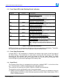
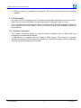
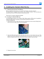
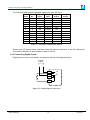
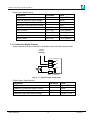
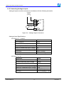
Teleterm
Silent Sentry
Models C2330B & C2331B
User’s Manual
Teleterm Silent Sentry C233xB User Manual
SCOPE
Products Covered by this Manual
This User Manual provides information on how to install, configure and use the Teleterm
Silent Sentry SMS Alarm Monitor.
This manual covers the following product Models:
Model
Description
C2330B
C2331B
Teleterm Silent Sentry SMS Alarm Monitor
Teleterm Silent Sentry SMS Alarm Monitor with Ethernet port
NOTE: This revision applies to Silent Sentry Software Version 3.02 upwards
Manual Revision History
Date
Revision Comments
12 Feb 2009
6
Released for C2330B and C2331B from C2330A Rev 5
5 Apr 2009
7
Minor error in message layout corrected in sections 3.3.1
and 3.3.6
30 Sep 2010
8
Added embedded messaging and Periodic timers.
Software Copy Available
This manual is available in Adobe Acrobat pdf format.
The pdf file is named UMC2330BR08.pdf
UMC2330BR08.pdf
2
-© Omniflex
Teleterm Silent Sentry C233xB User Manual
Table of Contents
Products Covered by this Manual ................................................................................................... 2
Manual Revision History.................................................................................................................. 2
Software Copy Available ................................................................................................................. 2
1. GENERAL DESCRIPTION ....................................................................................................... 6
1.1
Overview.......................................................................................................................... 6
1.2
Front Panel LED (Light Emitting Diode) Indicators ......................................................... 7
1.3
Front Panel Pushbutton................................................................................................... 7
1.4
Serial Port 1..................................................................................................................... 7
1.5
I/O Terminals ................................................................................................................... 8
1.6
Antenna Connection........................................................................................................ 8
2. Installing the Teleterm Silent Sentry ......................................................................................... 9
2.1
Connecting the Internal Clock Battery............................................................................. 9
2.2
Inserting the GSM Network SIM Card (Model C2330A only) .......................................... 9
2.3
Registering the Silent Sentry on the CDMA network (Model C2331A only) ................. 10
2.4
Mounting the Silent Sentry ............................................................................................ 10
2.5
Connecting Serial Port 1 ............................................................................................... 10
2.6
Connecting the Antenna................................................................................................ 11
2.7
Positioning the Antenna ................................................................................................ 11
2.8
Allocating direct Inputs and Outputs.............................................................................. 11
2.9
Connecting Digital Inputs .............................................................................................. 12
2.10
Connecting Digital Outputs............................................................................................ 13
2.11
Connecting Analogue Inputs ......................................................................................... 14
2.12
Connecting Analogue Outputs ...................................................................................... 15
2.13
Powering up the Silent Sentry ....................................................................................... 15
3. Principle of Operation of the Silent Sentry .............................................................................. 16
3.1
Basic Function ............................................................................................................... 16
3.2
Source of Message Triggers ......................................................................................... 16
3.2.1 Digital Inputs .................................................................................................................. 16
3.2.2 Analogue Input Set points.............................................................................................. 16
3.2.3 System Inputs ................................................................................................................ 16
3.2.4 Derived Inputs ................................................................................................................ 16
3.3
Messages ...................................................................................................................... 16
3.3.1 Message Format ............................................................................................................ 16
3.3.2 SMS Message Identifier ................................................................................................. 17
3.3.3 Common Message Text ................................................................................................. 17
3.3.4 Alarm Message Text ...................................................................................................... 17
3.3.5 Date and Time Text........................................................................................................ 17
3.3.6 Example Message.......................................................................................................... 17
UMC2330BR08.pdf
3
-© Omniflex
Teleterm Silent Sentry C233xB User Manual
3.4
Recipients...................................................................................................................... 17
3.5
Daily Update Message .................................................................................................. 17
3.5.1 Example Message.......................................................................................................... 18
3.6
Recipient Priorities ........................................................................................................ 18
3.7
Timer Settings ............................................................................................................... 18
3.7.1 Delay Time to Priority 2 Messages ................................................................................ 18
3.7.2 Delay Time to Priority 3 Messages ................................................................................ 18
3.7.3 Hold Off Time ................................................................................................................. 18
3.8
Acknowledging Messages............................................................................................. 19
3.9
SMS’s per Hour ............................................................................................................. 19
3.10
Use of the Modbus Link................................................................................................. 19
3.11
On Demand Messaging................................................................................................. 19
4. Configuring the Teleterm Silent Sentry ................................................................................... 21
4.1
Overview........................................................................................................................ 23
4.2
Incompatibility with Previous Versions of Omniset and DITview................................... 23
4.2.1 Versions of Omniset prior to 7.3 .................................................................................... 23
4.2.2 What if I have DITview installed?................................................................................... 23
4.3
Installing Omniset from the CD supplied ....................................................................... 23
4.4
Connecting Omniset to the Teleterm Silent Sentry for first time ................................... 24
4.5
Overview of the Silent Sentry Configuration Template ................................................. 25
4.6
Quick Configuration....................................................................................................... 25
4.6.1 Set the Real-time Clock ................................................................................................. 25
4.6.2 Set the I/O Points to Digital Input................................................................................... 26
4.6.3 Set the SIM Card PIN and Telephone Number (Model C2330A only)........................... 26
4.6.4 Configure the Messages in the Message List ................................................................ 27
4.6.5 Set the Recipient List ..................................................................................................... 28
4.6.6 Send the test Message .................................................................................................. 29
4.7
Configuring the Serial Port 1 ......................................................................................... 33
4.8
Other Configuration Settings ......................................................................................... 33
5. Modbus and the Silent Sentry ................................................................................................. 34
5.1
Overview........................................................................................................................ 34
5.2
Modbus Slave................................................................................................................ 34
5.2.1 Selecting the Slave Protocol Details .............................................................................. 34
5.2.2 Modbus Data Register Mapping .................................................................................... 35
5.3
Modbus Master.............................................................................................................. 35
5.3.1 Selecting the Master Protocol Details ............................................................................ 35
5.3.2 Query Blocks.................................................................................................................. 35
6. Maintenance............................................................................................................................ 37
6.1
Battery Type .................................................................................................................. 37
6.2
Battery Replacement Procedure ................................................................................... 37
UMC2330BR08.pdf
4
-© Omniflex
Teleterm Silent Sentry C233xB User Manual
7. Technical Support ................................................................................................................... 38
Table of Figures
Figure 2.1: Mechanical Mounting Dimensions for the Silent Sentry................................................ 10
Figure 2.2 - Digital Input Connections ............................................................................................. 12
Figure 2.3 - Digital Output Connections .......................................................................................... 13
Figure 2.4 - Analogue Input Connections........................................................................................ 14
Figure 2.5 - Analogue Output Connections ..................................................................................... 15
Table of Tables
Table 1.1 Front Panel LED Indicators ............................................................................................... 7
Table 2.1: Pin allocation of serial port 1 connector on Silent Sentry............................................... 11
Table 2.2 - I/O Point Configuration Options .................................................................................... 12
UMC2330BR08.pdf
5
-© Omniflex
Teleterm Silent Sentry C233xB User Manual
1. GENERAL DESCRIPTION
1.1 Overview
The TELETERM ‘Silent Sentry’ is an SMS (Short Message Service or Text Message) Alarm
Monitor capable of monitoring a wide range of signals and sending SMS Alarm messages
upon detection of any alarm condition.
The Silent Sentry is equipped with 12 direct Binary and Analogue Inputs, plus a Modbus port
allowing alarms from a variety of sources to be monitored.
Up to 64 different SMS messages can be sent. The Silent Sentry can be configured for up to
10 message recipients, each in one of three escalating priority groups. This allows SMS
messages to be sent to a selected group of recipients, and if not acknowledged within a set
time, then sent to the second group of recipients, and if still not acknowledged, then sent to
the third group of recipients. All messages are sent to all recipients in the priority order set.
The addition of a daily update SMS message capability ensures that the Silent Sentry is
always available to react to alarms when they occur.
The Silent Sentry is easily configurable, using the free Omniset configuration software. Using
Omniset PRO, the Silent Sentry can also be configured remotely over the mobile phone
network.
The “On-Demand” messaging feature allows an authorised user to send an SMS message to
the unit to read a value, change a setting, or write to an output.
The Silent Sentry can also be connected to your existing PLC’s, DCS, SCADA and alarm
annunciator systems using the Modbus serial port or optional Ethernet port to send SMS
Alarms from events within in your existing process.
Antenna Connector
Programming Port Connector
Optional Ethernet
SD Card Slot
Serial Port 1 Connector
Cover Screws
Wiring Terminals
SD Pushbutton
Figure 1.1: Front View of the Teleterm Silent Sentry with Ethernet port
UMC2330BR08.pdf
6
-© Omniflex
Teleterm Silent Sentry C233xB User Manual
1.2 Front Panel LED (Light Emitting Diode) Indicators
Legend
Colour
NET
Green
TX1
Red
RX1
Yellow
TX2
Red
RX2
Yellow
OK
Green
RUN
Green
SD
Green/Red
Description
Signal Strength Indicator
ON STEADY – Network is connected and signal
strength is acceptable
OFF – There is no network connection.
Serial Port 1 Transmit Activity
ON – The Silent Sentry is transmitting data out of the
Serial Port 1 (on the front of the unit).
Serial Port 1 Receive Activity
ON – The Silent Sentry is receiving data coming in on
Serial Port 1 (on the front of the unit).
Network Transmit Activity
ON – On when the Silent Sentry is communicating with
the internal network modem.
Network Receive Activity
ON – On when the internal network modem is sending
information to the Silent Sentry.
Silent Sentry OK Indicator
ON – Silent Sentry is operating correctly
OFF – No Power or the Silent Sentry is faulty
Silent Sentry is monitoring for alarms
ON – Silent Sentry is operating correctly
OFF – No Power or the Silent Sentry is faulty
SD Card Indicator
GREEN – SD Card is inserted and ready.
RED – Silent Sentry is writing data to the SD Card.
OFF – The light is normally off in the absence of an SD
card.
Table 1.1 Front Panel LED Indicators
NOTE: On Power up, all indicators will light for a few seconds during initialisation. Thereafter,
the indicators will resume their normal operation as per the table above.
1.3 Front Panel Pushbutton
A Serial PORT 1 “SD” pushbutton is located on the bottom right corner of the front plate of
the Silent Sentry. This pushbutton is used when removing the SD memory card. Before
removing the SD memory card, push this button to tell the Silent Sentry to pause
communication with the SD card, ad to close all open files so the card can be ejected. Wait
for the SD light to go off before ejecting the SD memory card
1.4 Serial Port 1
The Teleterm Silent Sentry is equipped with a serial port, labelled PORT 1, on the front of the
unit. This serial port is used to communicate with other equipment.
This serial port can be wired for RS232, RS422 or RS485 communications.
The serial port can be configured for one of two protocol sets:
a) Modbus protocol (Master or Slave device, ASCII or RTU protocol) is available on this port
allowing easy connection to other third party products such as Alarm Annunciators, PLC’s
DCS or SCADA systems.
UMC2330BR08.pdf
7
-© Omniflex
Teleterm Silent Sentry C233xB User Manual
b) Conet/s protocol is available for integration into Conet networks with other Omniflex
products.
1.5 I/O Terminals
The Silent Sentry is equipped with 12 software configurable input/output points (IO points).
Each IO point can be individually configured as digital or analogue, input or output.
Up to 12 digital inputs, 12 analogue inputs, 10 digital outputs, and two analogue outputs can
be configured on the Silent Sentry (12 direct I/O points in total). See installation section for
further details.
1.6 Antenna Connection
The antenna connection allows an external antenna equipped with an SMA male plug
connector to be used with this device.
A 0dB antenna is supplied with the Teleterm Silent Sentry. This antenna is provides
satisfactory reception for the majority of applications. For difficult reception areas, a high gain
antenna may be purchased from Omniflex.
UMC2330BR08.pdf
8
-© Omniflex
Teleterm Silent Sentry C233xB User Manual
2. Installing the Teleterm Silent Sentry
2.1 Connecting the Internal Clock Battery
Before installing the Silent Sentry, the internal clock battery must be connected.
The Silent Sentry is shipped from the factory with a “Battery Protector Tab” protruding from
the left side of the unit. Pull on the tab to remove before use.
See section 6 for battery replacement details.
2.2 Inserting the Network SIM Card
The GSM aligned models of the Teleterm Silent Sentry require a SIM card (not supplied) to
enable the Silent Sentry to operate on the selected mobile phone network.
To insert the SIM card:
1. Remove the top cover of the Silent Sentry by undoing the two hex screws holding the top
cover of the unit, using a 2.5mm hex key (supplied).
2. Insert the SIM card into the SIM card holder you will see in the centre of the unit. Take
special care that the SIM card is correctly seated in the connector, and that the SIM card
holder is properly closed. Press firmly down and slide forward to close securely.
3. Replace the top cover.
UMC2330BR08.pdf
9
-© Omniflex
Teleterm Silent Sentry C233xB User Manual
2.3 Registering the Silent Sentry on the CDMA network (Model C233xB-13 only)
The Teleterm Silent Sentry equipped with CDMA network connection must be registered on
the customer selected CDMA network before the unit can operate.
The Teleterm Silent Sentry for CDMA networks is supplied with an Electronic Serial Number
(ESN). This number can be found on a label attached to the unit.
This ESN must be supplied to the CDMA network operator when registering the unit for
operation on the CDMA network.
2.4 Mounting the Silent Sentry
The Teleterm Silent Sentry is designed to be clipped to one of the following mounting rails:
Top Hat Section (DIN) Rail 35/7.5mm in accordance with EN 60715: 1981
Top Hat Section (DIN) Rail 35/15mm in accordance with EN 60715: 1981
G Section Rail 32mm in accordance with EN 60715: 1981
109,5
Height including serial cable
54,5
46,5
155
7,5
45
89,5
5
Figure 2.1: Mechanical Mounting Dimensions for the Silent Sentry
2.5 Connecting Serial Port 1
Rhe selection of either RS232 or RS422/RS485 is achieved by specific wiring of the serial
port connector. No internal links need be changed to select between RS232 and RS422/485.
UMC2330BR08.pdf
10
-© Omniflex
Teleterm Silent Sentry C233xB User Manual
Pin
number
5
4
3
2
1
9
8
7
6
1
2
3
4
5
6
7
8
9
Communication Standard
RS232
Do not connect
Rx Data (In)
Tx Data (Out)
Do not connect
Ground
Do not connect
RTS (Out)
CTS (In)
Do not connect
RS485
Rx Data + (In)
Rx Data – (In)
Do not connect
Tx Data+ (Out)
Ground
Vcc
Do not connect
Do not connect
Tx Data – (Out)
Table 2.1: Pin allocation of serial port 1 connector on Silent Sentry.
NOTE: The RTS and CTS handshaking lines are available for applications that require them.
It is not a requirement of the CPU to use handshaking. In most applications connecting the
RTS and CTS handshaking lines is not necessary.
2.6 Connecting the Antenna
The supplied Antenna’s should be screwed directly into the Antenna socket. Do not over
tighten. This connector should be only finger tight to avoid damage. This connector is an
SMA Jack, and will accept any antenna connection with an SMA plug.
2.7 Positioning the Antenna
When using a remote antenna, the antenna should be placed away from the Silent Sentry in
a position that gives the best possibility of a good signal on the mobile phone network. Avoid
proximity of the antenna to shielding materials such as metal enclosures.
The signal strength of the chosen location can be easily checked by holding a mobile phone
(connected to the same network) in the intended position of the antenna, and checking that
the signal strength on the phone is good.
CAUTION: The antenna emits RF energy on a continuous basis, and should be positioned
away from sensitive instrumentation, and away from areas where close proximity to
personnel on a regular basis would occur.
2.8 Allocating direct Inputs and Outputs
The Silent Sentry has a unique feature of allowing each I/O point to be software configured
as analogue or digital, input or output, for the best possible utilisation of I/O in any
application.
UMC2330BR08.pdf
11
-© Omniflex
Teleterm Silent Sentry C233xB User Manual
The following table gives the possible options for each I/O Point:
I/O
Point
Terminal
No.
Digital
Input
Analogue
Input
Digital
Output
Analogue
Output
1
2
3
4
5
6
7
8
9
10
11
12
5
6
7
8
9
10
11
12
13
14
15
16
Yes
Yes
Yes
Yes
Yes
Yes
Yes
Yes
Yes
Yes
Yes
Yes
0-30Vdc
0-30Vdc
0-30Vdc
0-30Vdc
0-30Vdc
0-30Vdc
0-5Vdc
0-5Vdc
0-5Vdc
0-5Vdc
0-30Vdc
0-30Vdc
Yes
Yes
Yes
Yes
Yes
Yes
Yes
Yes
Yes
Yes
-
0/4-20mA
0/4-20mA
Table 2.2 - I/O Point Configuration Options
Review your I/O requirements, and then make the optimum allocation of the I/O, taking into
account the variations in specification of each I/O Point.
2.10 Connecting Digital Inputs
Digital Inputs must be connected in accordance with the following schematic:
9-30Vdc
Supply
-
+
1
2
3
4
+V
0V
n
IOP 1 - IOP 12
Figure 2.2 - Digital Input Connections
UMC2330BR08.pdf
12
-© Omniflex
Teleterm Silent Sentry C233xB User Manual
Digital Input Specifications:
Parameter
Condition
Value
LED Indication
Input On
Green LED On
Absolute Maximum Input Voltage
30Vdc
Minimum High Level Input Voltage
3Vdc
Maximum Low Level Input Voltage
2Vdc
Input Current
Vin = 5V
0.7mA (typical)
Input Current
Vin = 10V
1.7mA (typical)
Input Current
Vin = 12V
2.2mA (typical)
Input Current
Vin = 24V
4.7mA (typical)
Input Current
Vin = 30V
6.0mA (typical)
2.11 Connecting Digital Outputs
Digital Outputs must be connected in accordance with the following schematic:
9-30Vdc
Supply
-
+
-
1
2
3
4
+
n
+V
0V
+V
IOP 1 - IOP 10
Figure 2.3 - Digital Output Connections
Digital Output Specifications:
Parameter
Condition
Value
LED Indication
Output On
Green LED On
Maximum Continuous Output Current
50mA
Maximum Peak Output Current
10ms max
Minimum High Level Output Voltage
UMC2330BR08.pdf
200mA
+VPSU – 2.5V
13
-© Omniflex
Teleterm Silent Sentry C233xB User Manual
2.12 Connecting Analogue Inputs
Analogue Inputs must be connected in accordance with the following schematic:
9-30Vdc
Supply
-
+
1
2
3
4
-
+V
0V
0-5/30V
+
n
IOP 1 - IOP 12
Figure 2.4 - Analogue Input Connections
Analogue Input Specifications:
I/O Points 1-6, 11 and 12
Parameter
Value
LED Indication
None
Absolute Maximum Input Voltage
30Vdc
Input Impedance Minimum
1MΩ
Minimum Measurable Input Voltage
0V
Maximum measurable Input Voltage
30V
Resolution
33mV (10 bits)
Accuracy
0.1% of reading + 1 bit
I/O Points 7 to 10
UMC2330BR08.pdf
Parameter
Value
LED Indication
None
Absolute Maximum Input Voltage
30Vdc
Input Impedance Minimum
280kΩ
Minimum Measurable Input Voltage
0V
Maximum measurable Input Voltage
5.5V
Resolution
6mV (10 bits)
Accuracy
0.1% of reading + 1 bit
14
-© Omniflex
Teleterm Silent Sentry C233xB User Manual
2.13 Connecting Analogue Outputs
Analogue Outputs must be connected in accordance with the following schematic:
9-30Vdc
Supply
-
+
1
2
3
4
-
+V
0V
4-20mA
+
n
+V
IOP 11 - IOP 12
Figure 2.5 - Analogue Output Connections
Analogue Output Specifications:
Parameter
Value
LED Indication
None
Maximum Output Voltage Drive
+VPSU – 5.0V
Minimum Controllable Output Current
0mA maximum
Maximum Controllable Output Current
23mA minimum
Output Resolution
25μA
Output Accuracy
0.1% of reading + 1 bit
2.14 Powering up the Silent Sentry
Upon power up, the Silent Sentry will take approximately 90 seconds to initialise the system
and connect to the wireless network. During this time, no SMS messages will be sent.
Once initialisation is complete, the green Network Indicator (NET) will light to indicate that the
Silent Sentry is successfully connected to the network, and the Silent Sentry will begin to
monitor for alarms.
UMC2330BR08.pdf
15
-© Omniflex
Teleterm Silent Sentry C233xB User Manual
3. Operation of the Silent Sentry
3.1 Basic Function
The Silent Sentry scans a set of binary conditions within the Silent Sentry at least every
100ms, and sends an SMS message whenever the relevant condition changes.
A binary condition is a condition that can be in one of two states – either 0 (Off) or 1 (On).
These changes to the binary conditions are known as “message triggers”. Each SMS
message can set to be triggered by the source binary condition changing from either 0 to 1,
or from 1 to 0.
3.2 Source of Message Triggers
The following is a list of conditions that can be selected to trigger each message:
3.2.1 Digital Inputs
These are on/off inputs wired directly to the terminals of the Silent Sentry
3.2.2 Analogue Input Set points
The Silent Sentry can have up to 12 direct analogue inputs. Each direct analogue input
has four internal alarm set points associated with it. This allows the analogue input to
be monitored for up to four alarm settings, and a message sent if the analogue value
rises above or falls below each set point.
3.2.3 System Inputs
The Silent Sentry also monitors a number of internal conditions that can be used to
send SMS Alarm messages. These include Real Time Clock Battery status and I/O
Point failures.
3.2.4 Derived Inputs
The Silent Sentry allows you to configure up to 32 Derived Inputs. A Derived Input is
not a physical input, but an input based upon the value of a single Bit of information in
one of the Silent Sentry’s internal 16 bit Data Registers. Derived Inputs are used when
monitoring data via the Modbus link. In this case the Modbus link writes the data to be
monitored to a Data Register in the Silent Sentry, and then a Derived Input is
configured to monitor that data bit.
3.2.5 Periodic Timers
The Silent Sentry allows you to configure up to 4 Periodic Timer triggers. Any message
that is triggered by one of these 4 Periodic Timers will be continuously sent at the
configured period.
3.3 Messages
Up to 64 SMS messages can be sent to up to ten recipients on a time priority basis.
3.3.1 Message Format
The format of all alarm messages sent is as follows:
Line 1: Identifier and Common Message Text
Line 2: Specific Message Text
Line 3: The time since triggering of the message if the message is priority 2 or 3.
Line 4: Date and Time
UMC2330BR08.pdf
16
-© Omniflex
Teleterm Silent Sentry C233xB User Manual
3.3.2 SMS Message Identifier
The Silent Sentry gives each SMS message a unique ID number. This ID number is
sent as the first characters of the first line of each message (before the Common Text
message) to uniquely identify the message. When the ID reaches 999 it goes back to 1.
3.3.3 Common Message Text
This text of up to 40 characters is sent at the beginning of every message (after the
message ID). This is typically used to identify the location of the Silent Sentry or source
of the messages.
3.3.4 Alarm Message Text
This text of up to 40 characters is unique to each of the 64 messages.
3.3.5 Date and Time Text
The date and time sent in the fourth line of the message is the date and time that the
message was sent as read from the internal real time clock in the Silent Sentry.
This clock should to be checked for accuracy from time to time. The real time clock can
be adjusted using Omniset. (See 4.6.1 Setting the Real Time Clock).
3.3.6 Example Message
This is a typical alarm message:
341 Pump Station P304 2
Sump Level High 3
30 minutes ago 4
2005/07/04 10:31:16 5
Notes:
1. This up to three digit number is the unique message ID.
2. The balance of this line is the Common Message Text
3. This is the Individual Alarm Message Text
4. This line is only sent when the message has been delayed by the Priority setting.
5. The date and time is derived from the internal Real Time Clock in the Silent Sentry.
3.4 Recipients
A recipient is the mobile phone number to which you wish to send the SMS messages
Up to 10 recipients can be configured in the Silent Sentry.
All configured recipients receive all messages.
IMPORTANT: Recipient telephone numbers must be entered without any spaces or dashes
or other separating characters. The only allowable non-numeric character is a + sign at the
front of the number if the country code is included.
3.5 Daily Update Message
A daily message can be configured that will be sent once a day at the specified time. This
message is used to confirm that the Silent Sentry is still operating normally, even when no
alarms are occurring.
The recipients to whom this daily update message is sent can be individually selected.
This message has the following format:
Line 1: 123 Common Message Text
Line 2: Daily Update Message Text
Line 3: Date and Time
UMC2330BR08.pdf
17
-© Omniflex
Teleterm Silent Sentry C233xB User Manual
3.5.1 Example Message
This is a typical daily update message:
1231 Pump Station P304 2
I’m Alive 3
2005/07/04 10:31:16 4
Notes:
1. This three digit number is the unique message ID.
2. The balance of this line is the Common Message Text
3. This is the Daily Update Message Text
4. The date and time is derived from the internal Real Time Clock in the Silent Sentry.
3.6 Recipient Priorities
Each message recipient in the Silent Sentry can be placed in one of three escalating Priority
Groups.
When a message is triggered, the Silent Sentry first sends the SMS message to the Priority 1
Recipients.
If not acknowledged within a set time (called the “Time Delay to Priority 2 Messages”), then
the same message is sent to the Priority 2 recipients.
If still not acknowledged within a set time (called the “Time Delay to Priority 3 Messages”),
then the same SMS message is sent to the Priority 3 recipients.
The time delays to escalate the message to the next priority are common for all messages.
CAUTION: Even if no recipients are programmed for a given priority, the Silent Sentry will still
wait for the priority time-out before returning to wait for a trigger input. Therefore it is
recommended that the priority delay time be set to a minimum for unused priorities.
3.7 Timer Settings
There are three timers used in the Silent Sentry as explained below. Each timer has a
resolution of minutes.
3.7.1 Delay Time to Priority 2 Messages
This is the time that the Silent Sentry will wait after sending the message to all Priority 1
recipients before sending the same message to Priority 2 recipients. If an
Acknowledgment reply is received before this time has elapsed, then no further
message is sent, and the Silent Sentry returns to wait for a message trigger (see Hold
Off Timer).
3.7.2 Delay Time to Priority 3 Messages
This is the time that the Silent Sentry will wait after sending the message a second time
to all Priority 2 recipients before sending the same message to Priority 3 recipients. If
an Acknowledgment reply is received before this time has elapsed, then no further
message is sent, and the Silent Sentry returns to wait for a message trigger (see Hold
Off Timer).
3.7.3 Hold Off Time
Once an Alarm has been acknowledged, a hold off time can be set to prevent this
message from being sent again for the specified “hold off” time. This is used to prevent
an unstable process condition from sending an excessive number of SMS messages in
quick succession.
UMC2330BR08.pdf
18
-© Omniflex
Teleterm Silent Sentry C233xB User Manual
TIP: Because the timers are decremented every minute on the minute, the actual time delay
of each timer will be accurate to 1 minute. Thus, if a timer is set to 2 minutes, then the actual
time delay could be between 1 and 2 minutes depending upon when the event occurred in
relation to the minutes time base. Timers set to 1 minute may therefore timeout almost
instantly, and should therefore be avoided.
3.7.4 Periodic Timer Setting
Four periodic Timers can be configured (in minutes) to send messages periodically.
The period can be set from 1 to 6553 minutes.
3.8 Acknowledging Messages
Messages are acknowledged by sending an SMS to the Silent Sentry with one of the
following text strings in the message:
Ack
Yes
This acknowledgement message is most easily sent by replying to the message received
with one of the specified text strings. The reply can use lower or upper case letters.
3.9 SMS’s per Hour
An added protection is provided to limit the number of SMS’s that can be sent in any hour.
This is used to prevent an unstable process condition from sending multiple SMS messages
on a continuous basis, causing an excessive bill for SMS messages.
Set this limit to the maximum number of SMS’s that you expect to be sent in any hour (i.e.
from xxh00 to xxh59). This count is reset every hour on the hour.
3.10 Use of the Modbus Link
The binary conditions that trigger SMS messages can be based upon data received over the
Modbus link (either serial or Ethernet). This allows the Silent Sentry to be used to monitor
any instrument that has a Modbus port (Master or Slave) available, and to trigger SMS
messages based upon the conditions within the instrument.
This is achieved in three steps:
1. Configure the Silent Sentry to read the data from the instrument over the Modbus link,
and place the data in the set of “scratch pad” registers allocated for the purpose in the
Silent Sentry.
2. Configure derived inputs to monitor any of the bits in the scratch pad registers.
3. Configure SMS messages to be triggered by the derived inputs.
3.11 On Demand Messaging
The Silent Sentry is also capable of interpreting SMS messages sent to it that act as
commands. Several commands can be sent in a single message, each command separated
by the ‘;’ character that ends the command text. Each message must begin with the
password command; if an incorrect or no password is supplied, all commands will be ignored
and the return message “Denied” will be sent. Incorrectly formed commands are ignored.
The commands are as follows:
Command
UMC2330BR08.pdf
Description
Response
19
-© Omniflex
Teleterm Silent Sentry C233xB User Manual
Command
Description
Response
+<pwd>
Password string, where <pwd> is a 4
character password that must match
that stored in the unit.
Passwords are NOT case sensitive.
Enable confirmation SMS for all further
write commands in the message
Read digital input n, where n is the
input number from 1 to 12
None or ‘Denied’, depending upon
the accuracy of the password
supplied
?;
Xn;
Yn;
Read digital output n, where n is the
output number from 1 to 10
An;
Read analogue input, n where n is the
input number from 1 to 12
Read analogue output, n where n is
the output number from 11 to 12
Read counter input, n where n is the
counter input number from 1 to 12
Read Data Register, n where n is the
data register number in the Data
Interchange Table (DIT) from 0 to
8999.
Read Bit m of Data Register n, where
m is in the range 0 (LSB) to 15 (MSB)
n is the data register number in the
DIT from 0 to 8999.
Write the value b to digital output n
where
b=0 to turn the output OFF
b=1 to turn the output ON
n is the range 1 to 10.
Write the value z to analogue output n,
where z is in engineering units, and n
from 11 to 12.
Bn;
Cn;
Dn;
Dn.m;
Yn=b;
Bn=z;
Cn=z
Dn=z
Dn.m=b
UMC2330BR08.pdf
Write the value z to the counter input
n, where
z is in the range 0 to 4294967296.
N is the input number from 1 to 12.
Write the value z to the data register n
where
z is a number from 0 to 65535.
n is the data register number in the
DIT from 0 to 8999.
Write the value b to bit m in data
register n, where
b=0 to clear the bit
20
See the individual write commands
below for response details
“Xn=0;” for Digital Input n OFF
“Xn=1;” for Digital Input n ON
“Yn=0;” for Digital Output n OFF
“Yn=1;” for Digital Output n ON
“An=z;” where z is scaled engineering
value for the input
“Bn=z”; where z is scaled engineering
value for the output
“Cn=z;” where z is counter reading
“Dn=z;” where z is data register
contents expressed as an unsigned
16 bit number in the range 0-65535.
“Dn.m=0;” if the bit is clear
“Dn.m=1;” if the bit is set
After the command “?;”
“Yn=b;” where b is the value read
back from the output after the write
was executed.
After the command “?;”
“Bn=z;” where z is the value read
back from the output after the write
was executed.
After the command “?;”
“Cn=z;” where z is the value read
back from the counter after the write
was executed.
After the command “?;”
“Dn=z;” where z is the value read
back from the data register after the
write was executed.
After the command “?;”
“Dn.m=b;” where b is the bit value
read back from the data register after
-© Omniflex
Teleterm Silent Sentry C233xB User Manual
Command
Description
Response
b=1 to set the bit
m is in the range 0 (LSB) to 15 (MSB)
n is the data register number in the
DIT from 0 to 8999.
the write was executed.
3.12 On Demand Message Examples
If the password of a unit is set to “ABCD” then sample commands and responses are:
Command
Response
Y1=1;
None.
(Only messages that start with “+” will be
responded to.)
Denied.
(The password does not match)
X1=1;
(Input 1 is ON)
A2=41.00;
(The analogue input engineering value is
currently set to 41.00)
None.
(No response was requested)
Y1=1;
(Digital Output 1 is turned ON)
X1=0;A2=157.2;B11=53.112;
(Note no confirmation of the output write)
Y1=1;X1=0;A2=157.2;B11=53.112;
D350=0;D350=8;
(Note D350 was 0 before the write of bit 3,
and then 8 after the write.)
B11=20.2;
(Note commands are not case sensitive).
+FGHJ;Y1=1;
+ABCD;X1;
+ABCD;A2;
+ABCD;Y1=1;
+ABCD;?;Y1=1;
+ABCD;Y1=1;X1;A2;B11;
+ABCD;?;Y1=1;X1;A2;B11;
+ABCD;D350;D350.3=1;D350
+abcd;?;b11=20.2;
3.13 Embedded Messages
In order to receive a measured value via a triggered SMS message, the value in the DIT to
be read can be embedded within a message by using embedded functions. To embed a
function in a message place a $ sign before function. The following table shows the
embedded functions available:
UMC2330BR08.pdf
21
-© Omniflex
Teleterm Silent Sentry C233xB User Manual
Embedded
Function
Dx
Dx#y
Dx.y
Xx
Yx
Ax
Ax#y
Bx
Bx#y
Cx
Cx#y
$
$;
UMC2330BR08.pdf
Description
Embed DIT x.
Embed DIT x and display format with y decimal places.
Embed BIT y of DIT x.
Embed Digital Input x.
Embed Digital Output x.
Embed Analogue Input x, display format as configured.
Embed Analogue Input x, display format with y decimal places.
Embed Analogue Output x, display format as configured.
Embed Analogue Output x, display format with y decimal places.
Embed Counter Input x, no decimal places.
Embed Counter Input x, display format with y decimal places.
Insert a $ in the message.
Insert a ; in the message.
22
-© Omniflex
Teleterm Silent Sentry C233xB User Manual
4. Configuring the Teleterm Silent Sentry
4.1 Overview
The Teleterm Silent Sentry is configured using the ‘Omniset’ software utility version 7.3 or
above, through the programming port, using the programming cable provided.
Omniset is a Windows98/NT/2000/XP compatible software package designed to configure a
wide range of Omniflex products, including the Teleterm Silent Sentry.
Omniset is available in two versions:
The standard Omniset software is on the CD supplied with the Silent Sentry. Omniset may
also be downloaded for free from the Omniflex web site www.omniflex.com .
Omniset allows the Silent Sentry to be configured through the serial port on the front of the
unit.
Omniset PRO can be purchased from Omniflex, and provides additional features including
the ability to remotely dial in to the Silent Sentry to change configuration.
4.2 Incompatibility with Previous Versions of Omniset and DITview.
4.2.1 Versions of Omniset prior to 7.3
The Silent Sentry is only compatible with Omniset or Omniset PRO Version 7.3
onwards. If you have a previous version of Omniset installed on your computer, then
you need to upgrade to the latest version.
You can check which version of Omniset you have installed by opening Omniset and
then selecting the “Help>About…” menu item.
4.2.2 What if I have DITview installed?
The ‘DITview’ software utility cannot be used to configure the Silent Sentry.
DITview has been superseded by Omniset PRO.
Omniset 7.3 shipped with Silent Sentry can be installed together with DITview on your
computer. Alternatively, enquire with your Omniflex representative about upgrading
your DITview software to the latest version of Omniset PRO.
4.3 Installing Omniset from the CD supplied
Omniset is Windows98/NT/2000/XP compatible, and requires access to an RS232 port on
your Windows computer.
If your computer does not have a serial port available for use with Omniset, then inexpensive
USB-to-Serial Converter modules are readily available that can be used with Omniset.
To install Omniset from the CD supplied, follow these steps:
1. Insert the CD into the CD drive of your computer. The Omniset installation should start
automatically. If it does not, then, using Windows Explorer, navigate on the CD drive
to the ‘Omniset’ directory and double click the file ‘setup.exe’.
2. Follow the prompts on the screen to complete the installation.
3. Select the COM port that you wish to use with Omniset by selecting ‘COM Port’ on the
Data menu.
4. Omniset uses “templates” to customise its appearance to suit the product being
configured. Omniset is supplied with a complete library of templates for all Omniflex
products, including the Teleterm Silent Sentry. This library is frequently being updated
with new products and enhancements. If your computer is connected to the Internet,
UMC2330BR08.pdf
23
-© Omniflex
Teleterm Silent Sentry C233xB User Manual
you can easily check for and download the latest template library by selecting “Update
Template Library from Web…” on the Omniset File menu. Follow the prompts to
update your template library to the latest version. If you installed Omniset from the CD
supplied with your Silent Sentry, and you do not have access to the Internet then do
not worry. You will already have the template necessary to configure the Teleterm
Silent Sentry (although it may not be the latest version available).
TIP It is strongly recommended that you update your template library before attempting to
connect to your Silent Sentry, to ensure that you have the latest template for the product.
4.4 Connecting Omniset to the Teleterm Silent Sentry for first time
To setup the Teleterm Silent Sentry using Omniset, follow this procedure:
1. Plug the programming cable supplied into the progamming port on the front of the Silent
Sentry (marked PROG) and into a serial port on your computer.
2. Ensure that the Omniset software utility is running on your computer.
3. Select ‘Connect...’ from the File menu.
Select the ‘Teleterm’ Product Group when prompted, and press OK:
4. If successfully connected, you should see the following screen in Omniset:
5. Check that the your Product Name is confirmed (such as “C2330B Teleterm Silent
Sentry”) and that the Product/File Compatibility is ‘Yes’.
UMC2330BR08.pdf
24
-© Omniflex
Teleterm Silent Sentry C233xB User Manual
6. Make sure that the Sync button
is depressed, and that the Sync mode icon is
present in the Status bar at the bottom of the Omniset window. This indicates that
Omniset is in Sync mode, and that the data visible in Omniset is synchronised with the
Silent Sentry connected. In this Sync mode, any changes that you make in Omniset will
automatically be written to the Silent Sentry. If Sync mode is NOT enabled, then changes
you make to the configuration will NOT be written automatically to the Silent Sentry. You
can write these values manually to the Silent Sentry by selecting “Write Current Group” or
“Write All Groups” from the “Data” menu.
You are now ready to view or change any of the parameters in the Teleterm Silent Sentry.
4.5 Overview of the Silent Sentry Configuration Template
The pane on the left of the Omniset window shows a list of Groups of Items to be viewed or
changed, arranged in Folders. Select a Group in the group pane on the left, to see the
contents of the individual Items for that Group in the item pane on the right.
By selecting either a Group, or an Item, Help information will be displayed for that Group or
Item in the Help pane below the Item pane at the bottom of the Omniset window.
See the Omniset Help for a more detailed description of the operation of Omniset.
There are two important Groups in the left group pane:
The Real-Time Data Group contains the current status of all data items in the Silent Sentry.
Select one of the Real-Time Data Groups to see the current data in the Silent Sentry.
The Configuration Group contains all the Items that can be configured in a Silent Sentry.
The value of an Item in the right hand pane can be changed in a number of ways:
1. Double-click the Item or
2. Right Click the Item and select “New Value…” from the options provided.
Enter the new value in the dialogue box and then press Enter or the ‘OK’ button.
Once you have completed the configuration of your Silent Sentry, you should save your
configuration to your hard drive, so you have a backup of the configuration.
Remember that if your Omniset is not synchronised to your target Silent Sentry when you
make any changes in Omniset, these changes will not be written to the Silent Sentry until you
press the “Write” or “Write All” button.
4.6 Quick Configuration
This procedure is recommended to check the Silent Sentry operation for the first time. This
provides the minimum amount of configuration necessary to achieve a simple functional test,
using the digital inputs as message triggers. This will give you a good starting point for further
customisation to suit your specific application.
4.6.1 Set the Real-time Clock
The Real Time Clock Data Group shows the current date and time in the Silent Sentry,
the time and date of the last power down, and the time and date of the last power up.
To set the real-time clock, write the current time and date to the relevant Data Items in
this Data Group. The clock will run immediately from this new time when it is written to
the Silent Sentry. To change a data item, double the Item, or right click and select “New
Value…”.
UMC2330BR08.pdf
25
-© Omniflex
Teleterm Silent Sentry C233xB User Manual
4.6.2 Set the I/O Points to Digital Input
The default setting as shipped from the factory is with all inputs set as digital inputs.
Ensure that these inputs as set as Digital Inputs by selecting the I/O Points Group. This
gives a summary of each Input setting.
For detailed configuration of each Input, select the actual I/O Point in the left Group
pane.
4.6.3 Set the SIM Card PIN and Telephone Number (Model C2330A/B only)
Set the SIM Card PIN Code to the PIN Number supplied with the SIM Card. The Silent
Sentry will send this PIN code to the GSM modem each time it powers up.
Enter these numbers without any spaces or non-numeric characters.
TIP: SIM Cards are often supplied with the PIN Code disabled. While this does make
for easier commissioning, this is a security risk for unmanned sites. If you are unsure of
the PIN Code, you can test the correct operation of the PIN Code by inserting the SIM
UMC2330BR08.pdf
26
-© Omniflex
Teleterm Silent Sentry C233xB User Manual
card into a regular GSM mobile phone and checking the code works before inserting it
into the Silent Sentry.
CAUTION: If the incorrect PIN code is entered, then after three attempts to insert the
wrong PIN code (three power up cycles), the SIM Card will lock out further attempts.
The PUK Code supplied with the SIM Card will then need to be inserted to activate the
SIM Card again.
If this occurs, remove the SIM Card from the Silent Sentry, insert it into a regular GSM
mobile phone and follow the PUK insertion instructions.
4.6.4 Configure the Messages in the Message List
For each message that you wish to use, set the following:
1. Send Message on change to 0 or 1. This refers to the change of state of the
selected input required to trigger the message. When set to “On change to 1”, then
the message will be sent when the selected trigger bit changes from a 0 to a 1
value and vice versa. For digital inputs, the input value is 0 when the input is off,
and 1 when the input is on. By setting this to “On change to 1”, the message will
be sent when the selected digital input is turned on.
Test Example: For Message 1, set this to “On change to 1”
2. The “Message trigger source” identifies what value in the Silent Sentry will cause
the message to be sent.
Test Example: For Message 1, set the “Message Trigger Source” to “Digital Input
1”.
3. Set the Message Text that you wish to be sent in the SMS. This can be up to 40
characters in each message.
Test Example: For Message 1, set the Message Text to “Input 1 into ALARM”.
UMC2330BR08.pdf
27
-© Omniflex
Teleterm Silent Sentry C233xB User Manual
4.6.5 Set the Recipient List
The Recipient List identifies each of the telephone numbers of the people to whom you
wish to send the SMS messages. All messages are sent to all recipients. The priority
set for each recipient will determine the time delay before the message is sent to that
recipient.
Test Example: Set your own mobile phone number as the mobile number for Recipient
1, recipient 2 and recipient 3. Set the priority of recipient 2 to 2, and the priority of
recipient 3 to 3. This will cause the alarm message to be sent to your mobile phone up
to three times, until you acknowledge the message by replying with the word “Ack” or
“Yes”.
UMC2330BR08.pdf
28
-© Omniflex
Teleterm Silent Sentry C233xB User Manual
4.6.6 Send the test Message
No other settings are necessary to send your first message. To test the Test Example
settings above, momentarily energise Input 1 (by connecting terminals 1 and 5). The
Input 1 green LED will light while the input is energised. After a few seconds, you
should see the following SMS received on your mobile phone:
1 Omniflex
Input 1 into ALARM
2005/07/16 14:23:45
If you wait for the priority 2 Time-out period (as set in the Timer Settings Group), then
you will receive the message a second time because you added your mobile phone
number to Priority Group 2 as well.
If you now reply to the message, and type “Ack” or “Yes”, then the alarm will be
acknowledged, and the alarm message will not be sent to the priority 3 recipients.
If you have completed this test example successfully, then you are well on your way to
a successful implementation of the Silent Sentry Alarm Monitor!
4.7 Message Trigger Sources
There are various triggers that can be used to trigger an SMS message to be sent. These
include Digital inputs/outputs, Analogue alarm points, System Inputs, Derived inputs and
Periodic timers. These triggers are configured in the “Message List” static folder. First
configure the ‘Send Message’ setting to be either ‘On Change to 1’ or ‘On Change to 0’. Then
choose the ‘Message Trigger Source’ from the pull down box. The configuration of the trigger
source options are explained below.
4.7.1 Digital Inputs/Outputs
To set a Digital Input or Output as a Trigger Source, select the desired ‘Message
Trigger Source’ (Digital Input 1 to Digital Input 12 or Digital Output 1 to Digital Output
10). Also ensure that the corresponding I/O point is set as a Digital Input or Output in
the “I/O Points” folder.
4.7.2 Analogue Alarm Points
To set an Analogue Alarm point as a Trigger Source, select the desired ‘Message
Trigger Source’ (Analogue Input 1 to 12 and Alarm Point 1 to 4).
Set the corresponding I/O Point to ‘Analogue Input’ in the “I/O Points” folder and then
configure the Analogue I/O Point as follows:
UMC2330BR08.pdf
29
-© Omniflex
Teleterm Silent Sentry C233xB User Manual
1. Set the scaling to scale the Input Voltage to engineering units.
2. Enable the “Alarm Event” (1 to 4).
3. Set the “Alarm Event” to be a high alarm, or a low alarm.
4. Set the setpoint at which the Alarm will be triggered (in engineering units).
5. Set the Deadband for the Alarm.
The status of the Analogue Alarm points can be viewed under ‘RealTime Data’ ->’I/O
Status’ -> ‘Digital Inputs’.
4.7.3 Derived Inputs
To set a Derived Input as a Trigger Source, select the desired ‘Message Trigger
Source’ (Derived Input 1 to 32) and set the corresponding derived point by selecting a
DIT/BIT source as shown in the figure below:
UMC2330BR08.pdf
30
-© Omniflex
Teleterm Silent Sentry C233xB User Manual
4.7.4 Periodic Timers
To set a Periodic Timer as a Trigger Source, select the desired ‘Message Trigger
Source’ (Periodic Timer 1 to 4) and set the period of the corresponding timer under
“Configuration”->”Message Settings”->”Timer Settings”. This period is set in minutes
and the maximum period can be set to 6553 minutes. The current status of these timers
can be viewed under “RealtimeData”->”I/O Status”->”Timers”.
4.8 On Demand Messages
In order to be able to send the RTU “On Demand” Messages as described in section 3.11,
the On Demand ‘Password’ needs to be set, as well as the ‘Timezone’ and ‘Allowable time
window’.
UMC2330BR08.pdf
31
-© Omniflex
Teleterm Silent Sentry C233xB User Manual
The default factory password is OMFX, but this should be changed immediately. This
password needs to match the password in the On-Demand message sent to the RTU. OnDemand messages sent to this unit must contain this password for the messages to be
accepted. This password is NOT case sensitive.(i.e. ABC = abc). Up to 12 characters can be
used.
The Allowable Time Window is used to set the maximum difference in time allowable
between the time that the SMS was sent to the RTU and the current Silent Sentry clock time,
for the command to be executed. This prevents messages that have been delayed in the
network from being executed out of turn.
The Time Zone describes the Silent Sentry's current time zone. This setting is necessary to
resolve any difference between the time zone of the On-Demand message sender and the
time zone of the Silent Sentry.
Eg. With the On-Demand Settings as in the screenshot above, to send the RTU a SMS
message to query the status of Digital Input 1, the following SMS must be sent:
+OMFX;X1;
4.9 Embedded Functions
Embedded Functions are used to embed the value of a register in the Silent Sentry in the
message text.
In the above example, the value of Analogue Voltage 1 (formatted to 3 decimal places) is
embedded in the message by using “$A1#3” in the message text.
Refer to Section 3.13 for more embedded functions.
UMC2330BR08.pdf
32
-© Omniflex
Teleterm Silent Sentry C233xB User Manual
4.10 Sending Messages between RTU’s
It is possible for one Silent Sentry RTU to send SMS messages to another Silent Sentry
RTU. In order to do this, the first RTU needs to send an “On Demand” message to the
second RTU. If the configured Message Text begins with a password character (“+”) then
only the ‘Message Text’ will be sent. (The ‘message identifier’, ‘common message text’ and
‘Date and Time text’ will be omitted from the SMS).
4.11 Configuring the Serial Port 1
The serial port (Port 1) on the Silent Sentry comes equipped with Modbus Master (ASCII and
RTU), Modbus Slave (ASCII and RTU) and Conet/s protocols. The required protocol
including any address selection is made in the Configuration/Communications Group.
4.12 Other Configuration Settings
There are a number of other settings that can be made in Omniset to fully configure your
Silent Sentry. Browse through all of the Configuration Groups in Omniset. The Help box will
explain each of these additional settings.
UMC2330BR08.pdf
33
-© Omniflex
Teleterm Silent Sentry C233xB User Manual
5. Modbus and the Silent Sentry
5.1 Overview
A unique and powerful feature of the Silent Sentry is its ability to read data from any device
equipped with a Modbus port and send SMS Alarm messages based upon the contents of
that data.
Examples of equipment that can be interrogated for alarm data are instruments such as
PLC’s, SCADA packages, on-line analysers, flow meters etc.
Modbus is the most popular standard for the exchange of data between industrial
instrumentation today. Modbus is a well established reliable standard that is easy to use.
Modbus is a serial multi-drop Master/Slave protocol. This means that you can connect one or
more Slave devices to a Master device over a serial communication link. If only one Slave
device is being used, and the distance between the Master and Slave devices is less than
15m, then the simpler more popular RS232 electrical standard can be used. If two or more
Slaves are to be connected to the Master Device, or the distance between the devices is
greater than 15m, then the RS485 electrical standard must be used.
There are no internal settings in the Silent Sentry for selecting RS232 or RS485. All that is
required is to wire the appropriate pins of the serial connector for the chosen standard.
5.2 Modbus Slave
5.2.1 Selecting the Slave Protocol Details
Setting up Modbus Slave protocol only requires configuration of the serial port in the
“Configuration/Communications/Serial Port” group, including ASCII and RTU mode,
Baud Rate, Parity, number of Data bits and Stop bits etc.
The simplest operating mode for Modbus Slave is to configure the Silent Sentry (and
the Master Device) as follows:
UMC2330BR08.pdf
34
-© Omniflex
Teleterm Silent Sentry C233xB User Manual
5.2.2 Modbus Data Register Mapping
The Modus protocol in the Silent Sentry supports the reading and writing of a number of
different types of data: Digital Status Inputs, Coil Outputs, Input Registers and Holding
Registers.
These Modbus Data types are mapped to specific areas of the Silent Sentry’s Scratch
Pad Registers. It is not normally necessary to change this layout, but you may do so for
specific applications. The default settings are as follows:
The most efficient data type to use is Holding Register Read (Modbus Function 3) and
Holding Register Write (Modbus Function 16).
5.3 Modbus Master
5.3.1 Selecting the Master Protocol Details
Setting up Modbus Master protocol requires configuration of the serial port in the
“Configuration/Communications/Serial Port” group, including ASCII and RTU mode,
Baud Rate, Parity, number of Data bits and Stop bits etc.
5.3.2 Query Blocks
In order to use the Modbus Master facility in the Silent Sentry to get data from another
Modbus Slave, “Query Blocks” have to be configured that tell the Silent Sentry where to
get the data from which Slave, where in the Silent Sentry to place the data, and which
Modbus Function to use to acquire the data.
Up to 16 Query Blocks can be configured in the Silent Sentry:
UMC2330BR08.pdf
35
-© Omniflex
Teleterm Silent Sentry C233xB User Manual
In the example shown above for Query 01, each data item has the following meaning:
Query Type Cyclic: This means that the query will repeat on a timed cycle as set.
Update Time: This setting shows often the query will be sent – in this case every 500
milliseconds (0.5 seconds).
Modbus Function Number: There are number of types of messages called “functions”
that the Modbus protocol supports. Function 3 for reading general purpose Holding
Registers is the most commonly used for this purpose because it is the most efficient
for reading larger amounts of data.
Slave ID: This is the Modbus Address of the Slave device to be polled.
Slave Start Address: This is the address of the first Holding Register to be read from
the Slave device,
Range: This is the number of Holding registers to be read from the Slave device.
Local DIT Start: This is the starting address of the local Register in the Silent Sentry
where the data will be written. The registers in the range 350 to 399 are reserved for
this purpose in the Silent Sentry.
Once the Queries required are configured, then you need to unplug the programming
cable from the serial port, switch the serial port back to normal mode by holding down
the Mode pushbutton until the OK light is steady green, and then plug in the slave
device to the serial port.
UMC2330BR08.pdf
36
-© Omniflex
Teleterm Silent Sentry C233xB User Manual
6. Maintenance
6.1 Battery Type
The Silent Sentry is equipped with an internal clip-in battery for retaining the real time clock
during power failures.
This battery is a type CR2032 Lithium Battery. This battery is commonly available from
electronic stores or can be obtained from Omniflex by specifying Part Number 3.5701.001
It is recommended that the battery be replaced at least every three years, or when the
battery low indicator in the silent sentry shows LOW. (See the Real Time/Product Status
Group in Omniset.
6.2 Battery Replacement Procedure
To replace the internal battery proceed as follows:
1. Remove the top cover of the Silent Sentry by undoing the two hex cover screws on the
top of the unit. The cover is connected to the unit by the internal antenna cable, so be
careful not to place any strain on this cable while removing the cover or inserting the SIM
card.
2. You will see the battery toward the left lower side of the unit.
3. Unclip the old battery and replace with a new battery
4. Replace the top cover.
5. Restore power to the Silent Sentry.
6. Using Omniset, check that the Battery Indicator is showing “Healthy”
7. Take care in disposing of the old Lithium battery to preserve the environment, and to
prevent accidents.
UMC2330BR08.pdf
37
-© Omniflex
Teleterm Silent Sentry C233xB User Manual
7. Technical Support
Lifetime technical support for all Omniflex products is available by email on
[email protected].
Alternatively, you can check the knowledgebase on the Omniflex web site at www.omniflex.com.
COPYRIGHT AND PROTECTIVE NOTICES
1. The Copyright of this document and the associated drawings, is the property of Omniflex and
is issued on condition that it is not copied, reprinted or reproduced or transmitted in any form
or by any means, electronically, photocopying, mechanical or otherwise, nor its contents
disclosed, either wholly or in part, without the consent in writing of, or in accordance with the
conditions of a contract with Omniflex.
2. The publication of information in the document does not imply freedom from patent or other
protective rights of Omniflex or others.
3. Although every intention is made to ensure that performance figures and data are accurate the
company reserves the right to alter without notice any product or specification. Performance
figures and data must therefore be specifically confirmed by the company before they become
applicable to any tender, order or contract.
4. In the case of electrical components, enough data is included in the drawings to allow
maintenance of the equipment. However, if component availability or substitution information
is required please consult the factory for assistance, as it is impossible to include data on
every component in this document.
5. This product is sold without liability for consequential loss of any description.
UMC2330BR08.pdf
38
-© Omniflex