1
‘
USO0RE35554E
United States Patent [191
[11] E
Pompei et a].
[45] Reissued Date of Patent:
[54] RADIATION DETECTOR WITH
TEMPERATURE DISPLAY
4,481,417
[75] Inventors: Francesco Pompei. Boston; Michael
4,636,091
Jul. 8, 1997
11/1984 Inglee ................................. .. 250/3381
4,566,808
1/1986 Pompei et al. .
374/124
4,596,932
6/1986 Bulfa et al.
250/374
1/1987 Pompei eta].
374/124
4,730,940
4,784,149
W. Burke. Natick, both of Mass.
3/1988 Herber et a1. .... ..
374/127
11/1988 Berman et al. ....................... .. 128/664
[73] Assignee: Exergen Corporation. Wate‘rtown
U1‘HER PUBLICATIONS
Raynger User’s Manual. Raytek. Inc. (1983). pp. 1-17.
Microscanner E. Exergen Corporation Brochure 1985.
[21] Appl. No.: 222,324
[22] Filed:
Apr. 4, 1994
Primary Examiner—'l'homas B. Will
Assistant Examiner-Willie Morris Worth
Related U.S. Patent Documents
Attorney, Agent, or Firm-Hamilton. Brook. Smith & Rey
nolds. RC.
Reissue of:
[64] Patent No.:
Issued:
Re. 35,554
Patent Number:
4,874,253
Oct. 17, 1989
Appl. No.:
32,067
Filed:
Mar. 27, 1987
[57]
ABSTRACT
A radiation detector with temperature readout has a multi
[63]
Continuation of Ser. No. 778,046, Oct. 16, 1991, abandoned.
colored LED display divided into segments of zero degrees
to 9 degrees centigrade colored green. 10 degrees to 19
[51]
[52]
1m. (:1.6 ...................................................... .. G01J 5m
U.S. c1. ................... ..
574/121; 374/128
centigrade in red. Alternatively. two red segments are pro
vided for ranges of 20 degrees to 64 degrees centigrade and
[58]
Field of Search
65 degrees centigrade and above. respectively. The radiation
U.S. Applications:
... . . .
. . . . . .. 374/121. 124.
374/128. 129. 130. 133; 340/586. 600
[56]
References Cited
U.S. PATENT DOCUMENTS
3,282,106
3,444,739
3,777,568
11/1966 Barnes .................................... .. 73/355
5/1969 Trehame .... ..
..
374/124
12/1973 Risgin et a]. ...... ..
4,013,260
3/1977 McClatchie et al.
. 250/343
4,081,678
3/1978
Maul] ............... ..
.. 250/330
Dore ........... ..
4,317,998
3/1982
4,321,594
3/1982 Galvin et a1.
.. 250/357
4,343,182
8/1982 Pompei .......... ..
374/31
4,372,690
2/1983 Berman et al. ..
374/29
.. 340/567
degrees centigrade in yellow. and 20 degrees to 100 degrees
detector is automatically zeroed at ambient upon use and
provides a readout of temperature rise above ambient
throughout a scan of a subject. In one design. only one LED
for each segment of the display is illuminated at a time. An
audible signal is sounded at an increasing pulse ?requency as
the display is illuminated from the green segment to the red
segnent of measured temperature rise above ambient with a
constant tone for temperature rises above about 20 degrees
centigrade. In an alternative design a timing circuit allows
the detector to self operate for a predetermined length of
time. The detector sounds a ‘beep’ tone before automatically
shutting itself 011’. A Window made of germanium covers the
radiation sensor and ?lters out wavelengths not of interest.
4,420,265
4,456,390 12/1983
6/1984 Everest
Junkert et a1. ........................ .. 374/128
77 Claims, 4 Drawing Sheets
'
l
V+
8/;
9/ - //
euzzen é
I5
30/
I /7
93
//
R
_V+
-—1 D
'
Q
>
—V REF
6
V TO F
9/
.,0
8
75
l'
I
87.»
7/
0°
8
If‘
25
i
W
29
. _/ea
9.5
a
GREEN
LE
2T04
DB'JODERQ, 99
A
RED
Ql " lean
I
US. Patent
Jul. 8, 1997
Sheet 1 0f 4
Re. 35,554
86
0m
> 20 ° C
INVESTIGATE
IMMEDIATELY
(POTENTIAL
R
20.
/
l/
24 <—SCANN|NG
FIG 2
,:
26
zm o
wm?rloH
98765432|0
O
G
RE.0
m
mm
N.. cvewm
E2
amCA
E
0 TO IO° C
NO ACTION
K.)
F/G 3
Re. 35.554
1
2
RADIATION DETECTOR WITH
TEMPERATURE DISPLAY
degrees centigrade and the 10 degrees to 19 degrees centi
grade segments.
The detector establishes the reference temperature by an
Matter enclosed in heavy brackets [ ] appears in the
original patent but forms no part of this reissue speci?
cation; matter printed in italics indicates the additions
made by reissue.
This application is a continuation of co-pending appli
autozero circuit. The autozero circuit initially establishes a
high reference signal which results in a display signal above
the zero level of the bar graph. The high reference signal is
reduced until the display signal reaches the zero level of the
bar graph at which point the reference signal is held. During
cation Ser. No. 07/778,046 ?led Oct. 16, 1991, now
abandoned, which is a Reissue of Ser: No. 07/032,067, ?led
on Mar. 27, 1987, US. Pat. No. 4,874,253.
a subsequent scan of the target. the autozero circuit sums the
reference signal with a radiation signal indicative of the
amount of sensed radiation. This sum provides the display
signal.
BACKGROUND
DISCLOSURE OF THE INVENTION
Over time. the repeated normal use of electrical equip
An object of the present invention is to provide a device
ment causes electrical connections to become loose and
weak. The increased electrical resistance of such connec
tions can result in heating which presents a ?re hazard.
that is easily and quickly used by a relatively inexperienced
Insurance and utility companies have recommended guide
lines that establish temperatures which indicate that correc
tive action should be taken. In the past. inspection of
electrical equipment for such faults was unsafe. costly
and/or inaccurate. Infrared inspection has been used as a
fast. easy and very effective way of detecting electrical
20
technician to determine the heat losses and temperature rise
above a reference temperature of electrical equipment and
other sm'faces. Afurther object of the invention is to provide
such a device which is relatively inexpensive. portable and
accurate outdoors as well as indoors.
In one design of the invention. the device with an autozero
circuit is held on for about 30 seconds by a timing circuit.
problems by the heat generated. Infrared inspection is safe 25 The timing circuit automatically turns the device o? at the
end of about 30 seconds and sounds a ‘beep’ tone to signify
as no contact is made with the electrical equipment. It is cost
its turning off. The timing circuit and the autozero circuit are
effective and accurate as the equipment is not shut down.
reset each time the user turns on the power of the detector.
Infrared inspection can also be used to detect ?re from
sources other than electrical equipment.
The detector includes a multicolor display which responds
One such infrared detector is the Microscanner E manu— 30 to the sensor and provides an indication of the temperature
of a subject above the reference temperature. The display
factured by EXERGEN Corp. of Natick. MA. That detector
shows three colored segments. green. yellow and red signi
comprises a multicolor full bar graph display which
fying no problem. caution and danger readings respectively.
responds to a radiation sensor and provides a temperature
with or without numerical references. The green segment
signal of a subject above a reference temperature. The bar
graph display is arranged into three segments of about zero 35 corresponds to a temperature rise above reference of about
degrees centigrade to 9 degrees centigrade. about 10 degrees
to 19 degrees centigrade and about 20 degrees centigrade
0 degrees centigrade to 9 degrees centigrade. The yellow
and greater. Each segment is of a dilferent color. It is
degrees to 19 degrees centigrade. and the red segment
corresponds to a temperature rise of about 20 degrees
centigrade and greater. In another design of the invention. as
segment corresponds to a temperature rise of about 10
preferred that the segments are colored green. yellow and
red respectively. indicating the recommended guidelines of
insurance and utility companies for the indicated tempera
40
the segments are illuminated. a pulsed audible signal sounds
with increasing pulse frequency from the “no problem”
ture rise above ambient temperature. The green segment
segment to the “danger” reading segment
indicates an acceptable temperature rise. The yellow seg
ment indicates a potential problem and that reinvestigation
In accordance with another aspect of the invention. the
is needed. The red segment indicates an immediate problem. 45 autozero circuit establishes a reference signal by placing
The segments are illuminated from zero degrees to the
charge on a capacitor through a time controlled switch. The
indicated temperature to give a full bar indication of the
switch is closed by a timer upon the turning on of the device.
amount of radiation sensed by the radiation sensor. The red
The closed switch allows charge to be placed on the capaci
segment ?ashes on and off when a temperature rise above
tor. The timer holds the switch closed just long enough to
100 degrees eentigrade is detected.
50 charge the capacitor to a level indicative of the temperature
of the sensed reference. The timer also disenables the buzzer
The display includes elements which are driven in a
and display until the capacitor is charged to the level
piecewise linear fashion. The elements are grouped together
indicative of the temperature of the sensed reference. When
and each group is associated with a display driver. The
the timer opens the switch to the capacitor. the display and
display drivers respond to a display input indicative of the
amount of radiation sensed by the radiation sensor and 55 buzzer are enabled and the display illuminates. signifying
the autozeroing of the unit. During a subsequent scan of the
incrementally select display elements. Each driver responds
subject. the autoaero circuit sums the reference signal with
to a single incremental change in the display input for
a radiation signal indicative of the amount of sensed
ditierent selections of display elements. but different drivers
radiation. and this sum provides a display signal.
respond to different incremental changes for ditferent selec
tions of display elements. Thus. the display drivers provide
In another design of the invention. a low cost circuit
a piecewise linear approximation of temperature which is a
embodies the autozero circuit. and a display of 3 LED‘s
nonlinear function of the sensed heat ?ux.
signi?es safe. caution and danger readings. In the display
The display provides a wide range of temperatures by
only one LED at a time is illuminated. The autozero circuit
is like the one described above. During a subsequent scan of
each group of elements being divided into different tem
perature increments. Speci?cally. the 20 degrees centigrade
and above segment of the bar graph display is divided into
larger temperature increments than the 0 degrees to 9
65
the subject. the reference signal establishes by the autozero
circuit is summed with the radiation signal indicative of the
amount of sensed radiation. This sum drives two compara
Re. 35.554
3
4
tors to produce inputs to a 2 to 4 decoder which selects one
FIG. 3 is an enlarged illustration of the scale of the
multicolor bar graph of FIG. 1 with the guidelines recom
of the three LED’s. The second inputs to the two compara
tors are taken from voltage dividers which divide the refer
mended by insurance and utility companies.
ence voltage from the reference voltage generator. With low
temperatures. the summed signals are less than the voltage
needed to enable either comparator so only the green LED
is illuminated. With higher temperatures the sum enables
one comparator which causes the decoder to illuminate just
the yellow LED. “With even higher temperatures the sum
enables both comparators causing the decoder to illuminate
the red LED.
The buzzer sounds in reference to the three LED's. A slow
FIG. 4 is an electrical schematic diagram of the electrical
circuit used in an embodiment of the invention having a
timing circuit.
10
LED display.
continuous pulse frequency sounds for the temperatures
DESCRIPTION OF PREFERRED
EMBODIMENTS
Aradiation detector 12 comprises a boxlike housing 14.
This housing has an approximate dimension of 3%"X5"X5/s".
The ?at. handheld housing can be easily carried in a pocket.
sensed in the range of temperatures illuminating the green
LED. The pulse frequency increases for increasing tempera
tures within the green LED range up through the red LED
temperature range. The highest pulse frequencies sound
when sensed temperatures are in the temperature range for
A radiation sensor assembly 16 is positioned at one end of
which the red LED is illuminated with a constant tone
sounding for sensed temperatures above a threshold tem
perature.
20
In another design of the invention. the display is arranged
into four segments colored green. yellow. red. and a second
red respectively. The green segment indicates a sensed rise
in temperature of less than about 10 degrees centigrade
above ambient. The yellow segment indicates a temperature
FIG. 5 is an electrical schematic diagram of the low cost
electrical circuit of another embodiment of the invention.
FIG. 6 is an electrical schematic diagram of the electrical
circuit used in an embodiment of the invention having a four
25
rise of more than about 10 degrees centigrade and less than
about 20 degrees centigrade. The ?rst red segment indicates
a temperature rise between about 20 degrees centigrade and
about 65 degrees centigrade. The second red segment indi
the housing 14.
An LED bar graph display 18 is located at the end of the
housing 14 opposite to the sensor assembly 16. This par
ticular bar graph includes the scale from 0 degree centigrade
to 100 degree centigrade. As shown in FIG. 3. a 0 degree to
20 degree part of the scale is divided into 1 degree incre
ments. The 20 degree to 100 degree part of the scale is
divided into 10 degree increments. The 0 degree to 9 degree
segment is colored green indicating no need for corrective
action according to the guidelines recommended by insur
ance and utility companies. The 10 degree to 19 degree
segment is colored yellow indicating a need to reinvestigate.
The 20 degree to 100 degree segment is colored red indi
eating a need to investigate immediately. These inspection
cates a temperature rise above about 65 degrees centigrade.
‘The same autozero circuit is used as in the foregoing
embodiments to establish a reference signal. The sum of the
guidelines are detailed on one side of the housing 14. The
of the amount of sensed radiation drives three comparators 35 region 20 in FIG. 1 is illuminated from 0 degree centigrade
to the indicated temperature providing a full bar indication
to produce inputs to a 3 to 8 decoder which selects one of the
of radiation detected by the sensor assembly 16 relative to an
four LED‘s. The three comparators and 3 to 8 decoder
ambient reference established by an autozero circuit to be
operate in the same manner as the two comparators and 2 to
described. The segment colored red ?ashes on and 011° for
4 decoder in the other design where higher temperatures
detected temperature rise above 100 degrees centigrade.
enable an additional comparator which in turn causes the
In another embodiment of the invention. the bar graph
decoder to illuminate a respective LED.
does not include a numerical scale. Instead the bar graph
Further. a buzzer sounds in reference to the four LED’s as
includes the three segments colored green. yellow and red.
the buzzer did in the three LED embodiment with a constant
reference signal and a subsequent radiation signal indicative
tone sounding for sensed temperatures above about 20
degrees centigrade. A switch to disenable the buzzer allows
45
the user to scan a subject without the audible signals.
In accordance with another aspect of the invention a
germanium window is used to cover the radiation sensor.
The window ?lters out sunlight energy but allows the sensor
to respond to the heat energy of the subject or of a ?ame. the 50
heat energy being at a longer wavelength than the sunlight
energy. This ?ltering ensures greater accuracy of the device.
BRIEF DESCRIPTION OF THE DRAWINGS
The foregoing and other objects. features. and advantages
respectively indicating the corrective action recommended
by the insurance and utility company guidelines. Further in
another design of the invention the display includes the three
colored segments but is not illuminated to give a full bar
indication rather just a single level indication is displayed. In
another design of the invention. the display has two seg
ments colored red in addition to a green and yellow segment.
The ?rst red segment displays temperatures between about
20 degrees centigrade and 65 degrees centigrade. The sec
ond red segment displays temperatures above about 65
degrees centigrade.
55
of the invention will be apparent from the following more
In another design of the invention a pulsed audible signal
sounds at a di?erent pulse frequency for each colored
particular description of preferred embodiments of the
segment of the bar graph display. The pulse frequency
invention. as illustrated in the accompanying drawings in
increases as the detected temperature rise increases. A switch
to disenable the audible signal is also available in another
which like reference characters refer to the same parts
throughout the diiferent views. The drawings are not nec
design of the invention.
essarily to scale. emphasis instead being placed upon illus
FIG. 2 illustrates an example of the use of the device to
trating the principles of the invention.
scan a region to pinpoint a source of maximum radiation.
While directed to a neutral surface as in position 24. the
FIG. 1 is a perspective view of a heat detector embodying
this invention and having a multicolor bar graph display at
an end of a housing opposite to a radiation sensor;
FIG. 2 is a schematic illustration of use of the detector of
FIG. 1 to scan a radiation source.
65
indication 20 is set at a low region of the scale. The
indication 20 is automatically zeroed at this level and the
radiation sensor is then scanned across a wide ?eld to a
position 26. Within that ?eld. the sensor senses radiation
Re. 35 .554
5
6
from the light source 28. As indicated by the scale position
shown schematically between the two end positions 24 and
input from the output of the 30 second counter 33 and a low
voltage second input from the Q output of the D Flip Flop
26. the indication 20 rises to a maximum level at the position
30 at which the sensor is directed at the light source 28.
31. These two inputs produce a low voltage output from the
gate 40 which disables the set input D ?ip ?op 32. [thus
holding the buzzer 70 from sounding] so that the buzzer is
Having been automatically zeroed at the ambient
temperature. the indication 20 provides a reading of the
temperature rise above ambient. The maximum reading is
only sounded with clocking of the ?ip?op 32 by the voltage
to-frequency converter 92.
the measurement of interest and such reading is much more
After counter 33 counts the 30 seconds during which the
unit has been operating the voltage output of counter 33
readily picked up by an observer using a bar graph display
than a digital numerical display.
drops. causing the formerly high input to the gate 40 to
become a low voltage input Because the other input to gate
40 from the 6 output of D ?ip ?op 31 is also low. the output
of gate 40 becomes a high voltage output and thus [enables]
The electrical schematic diagram of the electrical circuit
used in one embodiment of the invention is illustrated in
FIG. 4. The unit is self operated for a predetermined length
of time after the
powering of the unit by way of a
timing circuit which includes a 30 second counter 33. In this
embodiment the initial powering of the unit begins by the
user squeezing the side of the housing 14 of FIG. 1. Upon
squeezing. the housing power is applied from the battery 82
through the switch SW1 of FIG. 4 to the V+ regulated line
which begins the counter 33. The switch SW1 is manually
held closed by the user long enough for the high voltage
sets the D Flip Flop 32. The buzzer 70 is thereby sounded
15
20
second u'me (low to high) by the 1 Hz oscillator 42. After 1
second. D Flip ?op 31 is clocked by the 1 Hz oscillator and
the 6 output from D Flip Flop 31 changes from a low to a
higr voltage. thus causing dissimilar inputs to the gate 40
and disabling the set input to the D Flip Flop 32 [from
further sounding the buzzer 70]. Thus just before the unit
across the V+ regulated line to close switch K1 through coil
K2 connected to switch K1. [Switch] After the switch SW1
opens, switch K1 maintains connection of the 9 V Battery 82
to lines (not shown) powering the rest of the circuit Switch
SW2 is connected to switch SW1 and thereby is closed at the
same time. The closing of switch SW2 resets [and powers
up] the autozero circuit 48, and sets D ?ip ?op 31.
[upon the next clocking of D ?ip ?op 32 from the voltage
output of the voltage to frequency device 92]. The Q output
from D Flip Flop 31 is delayed from changing voltages a
shuts itself off the buzzer sounds one last time.
25
The drop in voltage of the voltage output of counter 33 not
only sounds the buzzer 70 but also changes the Q output of
D ?ip ?op 31 from high to low. This low voltage causes coil
duces a negative reference signal which is applied through
K2 to open switch K1 and thereby shuts off the unit. A
subsequent squeeze of the housing 14 resets the autozero
reference signal held in buffer 47 and the 30 second counter
a bu?'er 47 to the summing node 66 where it is summed with
33 in the same manner as described above for
a subsequent negative radiation signal from IR sensor 83.
This summed voltage is ampli?ed in ampli?er 67. The
ering of the device.
The autozero circuit 48. as will be described later. pro
output voltage from ampli?er 67 triggers the display 78 to
provide an indication of the sensed radiation.
The output voltage from ampli?er 67 also controls the
voltage to frequency device 92 which controls the pulse
?’equency of buzzer 70. The output voltage is offset at
comparator 90 to produce the lowest duty cycle of the
voltage of frequency device 92 at ambient. The output
voltage form ampli?er 67 causes the voltage to frequency
device 92 to pulse the clock of the D ?ip ?op 32. Each time
the clock is pulsed. the D ?ip ?op 32 produces output Q
directly from input D. Output 6 leads into the D input of D
?ip ?op 32 so that after each pulsing of the clock a change
35
to frequency device 92.
ampli?er 67. Each display driver in display 78 responds to
the ampli?ed signal and incrementally selects light emitting
diodes to light the bar graph display.
Each display driver incrementally selects light emitting
diodes based on the high and low reference inputs for that
particular driver. The incremental change of each driver is
45
50
55
driver to the next are thus driven in a piece-wise linear
fashion. This results in each driver- responding to a single
incremental change in the ampli?ed signal for different
selections of light emitting diodes. but different drivers
responding to different incremental changes for different
selections of light emitting diodes. The display drivers
provide a piece-wise linear approximation of temperature
also triggered by the output voltage from ampli?er 67, the
increasing pulse frequencies of buzzer 70 correspond to the
increasing display indication.
[The buzzer 70 is refrained from sounding upon initial
powering of the device by the gate 40. During this time,]
which is a nonlinear function of the sensed heat ?ux.
Gate 40 causes the buzzer 70 to sound for one second as the
unit shuts itself of. Upon initigl powering of the device,
?ip?op 31 is set such that its Q output goes low, and the
30-sec0nd counter 33 is set such that its output is high.
Through the next 30 seconds. the gate 40 has a high voltage
de?ned at a voltage of one-tenth of the difference between
the high and the lows references. there being ten light
emitting diodes per driver. The light emitting diodes asso
ciated with each driver are linearly driven by that driver. The
low reference of the succeeding driver is set equal to the
high reference to the preceding driver. The voltage per
incremental change of the succeeding driver is then de?ned
by its high and low references which have a different
difference than the high and low references of the preceding
driver. The light emitting diodes selected from one display
As the temperature sensed by the sensor 83 increases so
does the output voltage from ampli?er 67. In turn. the
increased output voltage from ampli?er 67 causes the volt
age to frequency device 92 to produce a more frequent
clocking signal to D ?ip ?op 32 which causes an increase in
the pulsing frequency of buzzer 70. Because the display is
Display 78 operates as follows. The signal from the
thermopile sensor element 83 is ampli?ed in a preampli?er
69. At the summing node 66. the radiation signal from the
thermopile is summed with the reference signal from the
autozero circuit to be described. The sum is ampli?ed in an
in Q will result in a subsequent change in the D input so that
on the next clock pulse a change in Q will occur. Thus D ?ip
?op 32 ensures a 50% duty cycle of the buzzer 70 and the
frequency of the D ?ip ?op 32 is generated by the voltage
pow
65
In the particular embodiment. the display driver associ
ated with the light emitting diodes for the zero degree to 9
degree end of the bar graph has a low reference to zero mV
and a high reference voltage of 150 mV. A display driver
selects each additional LED in response to a voltage step of
Re. 35,554
7
8
15 mV to indicate a temperature change of 1 degree on the
bar graph. The low reference input to the succeeding driver
is 150 mV and the high reference is 320 mV to establish a
voltage step of 17 mV for each degree of change on the bar
FIG. 4 and which is designed for the minimization of
production costs. The autozero circuit of the embodiment in
FIG. 5 may also be used in the embodiment of FIG. 4. In
FIG. 5. an autozero reference signal is established by the
user closing switch 15 which is the power switch connecting
the 9 v battery 9 to the V+ and other lines of the circuit. The
radiation sensor 13 detects the radiation of the object at
which the device is initially pointing. Provided that the
initial object is at a temperature above ambient. the sensed
graph between the 9 degree and 19 degree segment.
The third display driver uses references which account for
both the linearization and the change in scale increment in
the 20 degree to 100 degree centigrade part of the bar graph.
The ?rst incremental change at which the third driver
radiation produces a negative voltage which is applied
through the dual operational ampli?ers 21 and 23 to produce
a gain in voltage.
responds provides the 1 degree centigrade change in tem
perature on the bar graph from 19 degree centigrade to 20
degrees. The remaining incremental change with the third
Switch 25 is closed by timer 11 when the device is turned
on. Switch 25 allows the negative voltage to charge the
capacitor 19 to a level indicative of the temperature of the
driver provide selection of the LEDs for the 10 degree
increments in the 20 degree to 100 degree segment of the bar
graph. A complication arises with the third driver because it
must provide a 1 degree increment from 19 degrees to 20
object toward which the device initially points. Timer 11
holds switch 25 closed about 500 msec which is long enough
degrees and 10 degree increments thereafter. To accomplish
for the capacitor 19 to be charged by the initial negative
this. the low reference is set at a level below 320 mV. the
voltage from the radiation sensor 13. At the end of the 500
msec. the timer opens switch 25 to discontinue the charging
high reference of the preceding driver. and the high refer
ence is set at 2.4 volts. The third driver. therefore. responds
20
to approximately 320 mV increments. The large incremental
change to which the driver responds sets the ?rst trigger
level at about (01064-0230) or at 0.336 mV. This is approxi
mately the input to which the second driver would have
buzzer 80 and enable the 2 to 4 decoder 75. The enablement
of the decoder causes the green LED to light. thus signifying
that the unit has been autozeroed.
responded if it had one more stage responding to 17 mV
increments. Beyond the 0.336 mV. the driver increments the
display at 230 mV increments. Those increments account for
The negative charge held by the capacitor 19 is applied to
the third piece of the piece-wise linear approximately of
temperature with ten degree increments.
As previously stated. at the beginning of each scan
of the capacitor 19. The initial high voltage output of the
timer 11 also holds the buzzer 80 ct? and disables the display
decoder 75 while the capacitor 19 is being charged After the
allotted time. the timer output voltage drops to reset the
a buffer 27. The negative voltage output of buffer 27 is the
autozero reference signal which is later input to differential
30
ampli?er 29 with subsequent radiation signals from ampli
illustrated in FIG. 2. the display is automatically zeroed at
the ambient temperature of the neutral surface at which the
?er 23 indicative of temperatures sensed by sensor 13. The
device is ?rst pointed. using an autozero circuit as com
indicative of the difference between the reference tempera
ture and the temperature being observed. The voltage drives
comparators 71 and 73 to produce inputs at ‘A’ and ‘B’ of the
2 to 4 decodm 75. The second inputs to the comparators are
taken from a voltage divider of resistors 87. 88 and 89 which
monly known in the art. Referring to FIG. 4. power is
applied from the battery 82 through switch K1 to the entire
circuit. The transition to a high potential results in a positive
pulse at an opposite side of a capacitor in autozero circuit 48
which triggers a comparator. A negative pulse results at the
output of the comparator to draw current through a diode and
a resistor and place a negative charge on a reference capaci
tor. That negative potential is applied through a buffer 47 to
the summing node 66 where it is summed with the negative
output voltage from ampli?er 29 is a positive voltage
35
divides the reference voltage from the reference voltage
generator 91. With low temperatures the output voltage from
differential ampli?er 29 is less than that across resistor 89
and neither comparator is enabled. With somewhat higher
temperatures the output voltage surpasses that across resistor
radiation signal. The charge initially placed on the reference
capacitor establishes a high negative reference signal which
results in the display 78 being set well above the zero degree
89 and comparator 73 is enabled. With yet higher tempera
45
centigrade level of the bar graph. The high reference signal
is then reduced by bleeding the charge from the reference
capacitor until the display 78 reachbes the zero level of the
bar graph. The reference signal is reduced at a decreasing
rate as the display 78 approaches the zero level of the bar
50
tures the voltage across resistors 87 and 89 is matched and
comparator 71 is enabled. The decoder 75 selects one of
three outputs placing a high voltage on one of three display
LED‘s connected to the decoder outputs. If the voltage
differential is below about 166 mv then comparators 71 and
73 produce low outputs to the decoder inputs ‘A’ and ‘B’
producing a high voltage output of the decoder 75 at Q0
graph. This is accomplished by tapping the input to the LED
which illuminates just the green LED. 166 mv is the amount
at the 10 degree level of the bar graph so that when the
display 78 reaches this level. a D ?ip-?op opens one switch
reducing the rate at which charge is bled off from the
reference capacitor. Likewise. input to the LED at the zero
of voltage that would result from detecting a 10 degree
centigrade rise in target temperature above ambient. If the
di?erential is between about 167 mv and 316 mv. then
55
comparator 73 places a high voltage input at ‘A’ and
comparator 71 places a low voltage at input ‘B’. Those
degree level of the bar graph is tapped to provide an
indication of the display 78 approaching the zero degree
level. A second D ?ip-?op is then triggered and a second
switch stops the bleeding of charge from the reference
capacitor. The amount of charge of the reduced reference
signal is inversely related to the radiation sensed from the
ambient surface and is reproduced at the output of buffer 47
inputs are decoded to produce a high voltage output at Q 1 to
illuminate just the yellow LED. The green LED is dimmed
at output Q0 is now low. 317 mv is the amount of voltage
indicative of a 20 degree centigrade change in sensed
temperature. If the differential voltage is above about 317
mv then there are high inputs to decoder 75 at both ‘A’ and
to be added to each signal from the radiation sensor 83
‘B’. producing a high output at Q3 which illuminates just the
throughout the scan. The display 78 is thus autozeroed and
red LED and low outputs at Q0 and Q1 which dim the green
and yellow LED’s.
The output voltage from ampli?er 29 also controls the
voltage to frequency device 10. This voltage is offset by the
provides readings of the temperature rise above ambient.
Shown in FIG. 5 is another embodiment of the invention
with a different autozero circuit than in the embodiment of
65
Re. 35.554
9
10
reference voltage. preferably about 2.5 v to 3.4 v from
The output is about 7.39 mv/btu/hr/sq ft sensed above or
below the autozero target. That is. the output voltage from
ampli?er 56 is a voltage indicative of the difference between
VREF91 at comparator 8 to produce the lowest duty cycle
of the voltage to frequency node 10 at ambient. The output
voltage ?'om ampli?er 29 causes the voltage to frequency
node 10 to pulse the clock of the D ?ip ?op 17. Each time
the clock is pulsed. the D ?ip ?op 17 has an output Q directly
dependent upon input D. The output 6 is connected to the D
the reference temperature and the temperature being
observed. The voltage drives comparators 63. 72. and 76 to
produce inputs to a 3 to 8 decoder 45. The second inputs to
the comparators are taken from a voltage divider of resistors
54. 3. 7 and 5 which divides the 2.53 V reference voltage
from reference voltage generator 85 into voltages corre
input so that after each pulsing of the clock a change in
Q will result in a subsequent change in D which in turn
produces a change in Q on the next pulse of the clock. Thus
the D ?ip ?op 17 ensures a 50% duty cycle of the buzzer 80
sponding to the sensed change in radiation with the change
in temperatures of the display. With a low sensed change in
radiation. the output voltage from ampli?er 56 is less than
and the frequency of the D ?ip ?op 17 is generated by the
voltage to frequency device 10. In turn. as the output voltage
from ampli?er 29 increases. the voltage to frequency device
10 produces a more frequent clocking signal to D ?ip ?op 17
that across resistor 5 and none of the three comparators are
15
which causes an increase in the pulsing frequency of buzzer
80. Also. as the temperature sensed by the sensor 13
increases. the output voltage from ampli?er 29 increases to
produce an increase in pulse frequency of the buzzer 80. The
increasing pulse frequencies of the buzzer 80 correspond to
the green. yellow and red LED’s respectively. A slow
continuous pulse frequency sounds for the temperatures
sensed in the range of temperatures illuminating the green
LED. The pulse frequency increases for increasing tempera
enabled. The decoder 45 in turn illuminates only the green
LED. With a somewhat higher change in sensed radiation.
the output voltage surpasses that across resistor 5. and
comparator 76 is enabled. Comparator 76 then places a high
input to decoder 45 which causes the decoder to illuminate
20
tures within the green LED range and continues to increase 25
through the yellow and red LED temperature range. The
fastest pulse frequencies sound when sensed temperatures
are in the temperature range for which the red LED is
illuminated. the voltage to frequency device 10 reaching a
the yellow LED and dim the green LED. With a higher
change in sensed radiation the voltage across resistors 3 and
7 is matched and comparator 72 is enabled. Comparator 72
in turn places a high input to decoder 45 which causes the
?rst red LED to be illuminated and the yellow LED to be
dimmed. With yet a higher change in sensed radiation. the
voltage across resistors 54 and 3 is matched and comparator
63 is enabled. Comparator 63 places a high input to decoder
45 which in turn selects to illuminate just the second red
LED.
The output voltage from ampli?er 56 also controls the
voltage to frequency device 60 which pulses the clock of D
?ip ?op 68 sounding buzzer 43 in a manner similar to that
described in the circuit of FIG. 5. The output voltage is offset
limit and causing the buzzer 80 to emit a constant tone for
sensed temperatures above about 20 degrees. By pressing
switch 81. the user can disable the buzzer 80 for situations
where the audible signal is not wanted.
by the reference voltage from reference voltage generator 85
In an alternative embodiment. a four LED display is
driven by three comparators and a 3 to 8 decoder as shown
in FIG. 6. The rest of the electrical circuit is the same as in
the embodiment of FIG. 5. The four LED’s of the display are
at comparator 52 so that the voltage to frequency device 60
is at its lowest frequency at ambient and at its highest
colored green. yellow. red. and a second red respectively.
One LED at a time is illuminated. The green LED signi?es
a temperature rise above ambient of up to about 10 degrees
Centigrade. The yellow is illuminated for a sensed tempera
ture rise between about 10 and 20 degrees centigrade. The
?rst red LED is illuminated for sensed temperature rise
between about 20 and 65 degrees centigrade. The second red
LED is illuminated for sensed temperature rise above about
35
frequency when near the 20 degree centigrade sensed
change in radiation threshhold. Once this threshhold is
crossed the buzzer 43 will sound continuously. The buzzer
sounds with increasing pulse frequency corresponding to the
green. yellow. and two red LED's respectively in the same
manner as the buzzer 80 in the embodiment of FIG. 5. The
buzzer 43 can be disabled by the user pressing switch 22 for
applications where the audible signal is not wanted.
45
65 degrees centigrade.
Power switch 55 is closed by the user upon operation of
the device. Power switch 55 connects battery 39 to the lines
of the circuit. Timer 6 is in turn powered and closes switch
62 for about 0.5 seconds. During this interval. the negative
voltage produced by the IR sensor corresponds to the
ambient object at which the device is pointing. This voltage
is ampli?ed by ampli?ers 41 and 44. and stored on capacitor
50
charged At the end of the 0.5 seconds. the timer 6 opens
switch 62 to discontinue the charging of capacitor 64. reset
the buzzer 43. and enables the decoder 45 allowing the greed
LED to light signifying that the device is autozeroed.
The negative charge held by capacitor 64 is applied to
buffer 46. The negative voltage output of buffer 46 is the
autozero reference signal which is later input to di?erential
ampli?er 56 with radiation signals from ampli?er 44 indica
have relatively long wavelengths which can be readily
distinguished with a wide range of ?lters. A further
consideration. however. is that a user is likely to want to
assure proper operation of a device by viewing a known hot
64. The timer 6 also holds buzzer 43 oil’ and disables the
decoder 45 powering the display until the capacitor 64 is
Wavelengths are shorter from hotter sources of radiation.
The device must detect wavelengths which are short relative
to those from bodies at ambient temperature. On the other
hand. the radiation from the very hot sun is of very short
wavelengths and sunlight should not be detected. Relative to
the radiation from the sun. overheated electrical connectors
source such as a match or light bulb. Such sources produce
55
radiation of wavelengths much closer to those of sunlight
and require much more speci?c ?ltering to allow for their
detection to the exclusion of sunlight.
To ensure accurate infrared detection out of doors. a
window 86 made of germanium covers the radiation sensor
within the radiation sensor assembly 16 of FIG. 1. A lens
comprising germanium is also suitable. The germanium
window 86 or lens acts as a ?lter allowing only energy of
certain wavelengths to be detected by the radiation sensor.
tive of temperatures sensed by sensor 37. For targets emit
The germanium glass ?lters out short wavelengths of less
ting more energy than the autozero reference target ampli?er 65 than about 1.7 microns from detection by the radiation
56 has a positive output. and for targets emitting less energy
sensor. 90% of the wavelengths in sunlight are less than 1.5
than the autozero target ampli?er 56 has a negative output.
microns. Although the wavelengths of energy from hot
Re. 35.554
12
11
a timing circuit means which maintains the detector in
electrical connectors are signi?cantly greater than 1.5
microns. it is desirable to detect shorter wavelengths result
ing from the ?ame of a match to assure proper operation of
operation for a predetermined length of time and there
after automatically shuts o?‘ the detector. said reference
temperature signal being reset when the detector is
turned on subsequent to its automatically shutting off.
said timing circuit means comprising:
the unit. The ?ames of interest are on the order of about
2000° F. to 2500° F. and produce wavelengths of about 1.7
to 3 microns with a peak at about 2 microns. Thus the
germanium glass ?lters out about 90% of the sunlight energy
a counter;
and only rejects about 10% of the energy of a ?ame.
a power switch by which a user initially connects a battery
to said counter and means for establishing the reference
The germanium window 86 serves a further purpose of
temperature signal;
preventing sunlight from burning out the sensor. Because the
wavelengths of sunlight and other visible light are short. less
an internal switch which is closed after the battery is
connected to said counter and means for establishing
than about 1.5 microns. it takes a very short time of exposure
to such light to over expose and thus burn out the sensor.
the reference temperature signal. said internal switch
closed maintaining the connection of the battery to
Hence. by the germanium window 86 ?ltering out the short
wavelengths of sunlight and other visible light. the sensor is
safeguarded against over exposure and subsequent burn out.
circuits of the detector thereby allowing a user to
release the power switch and the detector to maintain
In the past. coated germanium windows were used as long
wave pass ?lters. Coated germanium starts passing wave
lengths at about 7 to 8 microns. Thus a coated germanium
window would not allow detection of the shorter wave
lengths of a ?ame test. Consequently. applicant uses
itself in operation. state of said internal switch being
dependent on an output signal from said timing circuit
means; and
20
uncoated germanium glass for window 86.
In contrast. ordinary glass ?lters out wavelengths [less]
greater than about 3 microns. [Ordinary glass rejects about
30-40% of the wavelengths of a ?ame. Other glass ?lters.
however. are suitable and may be used in place of window
86.] In general. it is best to have a long wave pass ?lter and
sensor which provides a threshold between about 1.5 and 3.0
microns.
Another problem with the outdoor use of past detectors is
the glare from sunlight causing di?iculties in reading the
detector display. In the present invention. this problem is
overcome by the audio indication of the detected tempera
ture rise above ambient. A continuous. slow pulsing ‘beep’
means for producing an audible signal dependent on a
control signal from said counter and a second output
signal from said timing circuit means. said audible
signal sounding when said counter reaches a predeter
mined count and. said timing circuit means thereafter
25
turns otf the detector by opening the internal switch.
2. Aradiation detector as claimed in claim 1 wherein said
display is arranged in segments of dilferent colors.
3. A radiation detector as claimed in claim 2 wherein the
colors of said segments are green. yellow and red. respec
30
tively.
4. Aradiation detector as claimed in claim 1 wherein said
display has segments arranged to indicate temperature from
about zero degrees centigrade to about 9 degrees Centigrade.
about 10 degrees to about 19 degrees centigrade. and about
tone indicates that a minimal temperature above ambient is 35
being detected. ‘Beeps’ at a faster pulse frequency indicate
20 degrees centigrade and greater. respecu'vely.
5. A radiation detector as claimed in claim 1 wherein. the
means for producing an audible signal includes means
that a greater temperature is being detected. The user is made
aware of a detected dangerous level of temperature rise by
producing an audible signal having a pulse frequency that
increases in correspondence with each temperature increase
a ‘beep’ signal sounding at a pulse frequency faster than the
other two mentioned frequencies. Thus. the use of the
detected by the sensor and indicated in the display. the
detector is not dependent on a light display which is often
means being associated with the signals indicative of
dil?cult to read in sunlight. This feature of an audible
detected radiation.
indication of the detected temperature is discussed and
6. A radiation detector as claimed in claim 1 further
described above.
comprising an autozero circuit which establishes the refer
Further. the audible indication provides a means to alert 45 ence temperature signal which is summed with said signal
the user of a temperature rise while scanning a subject. Once
indicative of detected radiation to produce a display signal.
the user is alerted by an increase in pulse frequency. a
the autozero circuit comprising means for establishing the
quantitative analysis of the sensed temperature rise may be
obtained by the display. Hence. the user can scan a subject
reference temperature signal indicative of ambient tempera
ture and means for holding the reference signal. the display
without speci?cally knowing where to look for potential
assembly means being responsive to the display signal.
heat problems. locate the problem area with the audible
signal. and now knowing where to focus the detector quan
reference temperature signal is established by placing a
tify the detected radiation with the display.
While this invention has been particularly shown and
described with references to preferred embodiments thereof
7. A radiation detector as claimed in claim 6 wherein said
55
it will be understood by those skilled in the art that various
changes in form and details may be made therein without
departing from the spirit and scope of the invention as
voltage on a capacitor.
8. A radiation detector as claimed in claim 1 further
comprising a window. the window covering said sensor to
?lter out short wavelengths on the order of less than about
1.5 microns while allowing longer wavelengths of about 1.5
to 3 microns and greater to be detected by said sensor.
9. A radiation detector as claimed in claim 8 wherein the
de?ned by the appended claims.
window comprises germanium.
We claim:
1. A radiation detector comprising:
10. A radiation detector comprising:
a radiation sensor‘,
a radiation sensor providing a radiation signal indicative
of sensed radiation;
a display assembly means responsive to a reference
temperature signal and [sinals] signals indicative of
radiation levels detected by the sensor for providing on
a display an indication of the temperature of a subject
above a reference temperature; and
an autozero circuit which establishes a reference signal
65
which is summed by summing means with the radiation
signal from the radiation sensor to provide a display
signal;
Re. 35 .554
14
13
a display assembly responsive to the display signal and
for each increase in amount of sensed radiation indicated by
having a multicolor display for providing a visual
indication of the amount of radiation sensed by the
radiation sensor. the display arranged in segments of
di?’erent colors;
the display. [where] wherein the timer disables the audible
signal producing means [from] to inhibit the sounding of the
audible signal during the time in which reference signal
voltage is placed on the capacitor and enables the audible
signal producing means to sound the audible signal there
after when the display in illuminated.
5
a sound generator means for generating an audible signal
with differing pulse frequencies. each pulse frequency
15. A radiation detector as claimed in claim 14 wherein
the means for producing an audible signal includes a buzzer
corresponding to an amount of radiation indicated by
the display such that the pulse frequency increases for
which is disabled and enabled by a switch controlled by the
increasing amount of radiation indicated on the display
means for ?ltering out short wavelengths on the order of
less than about 1.5 microns while allowing longer
user.
16. A radiation detector as claimed in claim 11 further
comprising:
wavelengths above about 1.5 microns generated by
means for producing an audible signal having a pulse
frequency that increases for each increase in amount of
sources of interest to be sensed by the sensor; and
a timing circuit initialized when power is applied to the
detector and which maintains power supply to circuits
of the detector for a predetermined length of time
through control of an internal power switch means and
thereafter automatically shuts off the detector by apply
ing a control signal to the internal power switch means
and a signal to actuate the sound generator means prior
sensed radiation indicated by the display[. the]; and
means for [producing] disabling production of the audible
signal [being disabled by said timing means] during the
time in which the reference signal is established, and
20
17. A radiation detector as claimed in claim 16 wherein
the means for producing an audible signal includes a buzzer
which is enabled and disabled by a switch controlled by a
to shut-off of the detector. said reference signal being
reset when the detector is turned on subsequent to its
automatically shutting off.
11. A radiation detector comprising:
[enabled thereafter] for enabling production of the
audible signal after the reference signal is established.
25 user.
18. A radiation detector as claimed in claim 11 wherein
a radiation sensor;
a display assembly means for providing on a segmented
illuminatable display [in] an indication of the amount
of radiation sensed by the radiation sensor above a
reference amount of radiation;
an autozero circuit comprising time controlled means for
placing a voltage on a capacitor for establishing a
reference signal indicative of a reference amount of
the display includes:
a green LED for indicating the detection of an amount of
30
radiation;
a yellow LED for indicating the detection of an amount of
radiation which has a corresponding temperature
within a range of temperatures higher above the tem
perature corresponding to the reference amount of
radiation than the range of the green LED; and
radiation detected by the radiation [sensor; and] sensor
from a reference target;
means for summing the reference signal [being summed]
with a radiation signal indicative of the amount of
a ?rst red LED for indicating the detection of an amount
sensed radiation subsequently detected by the radiation
sensor to provide a display signal, the display assembly
means being responsive to the display signal and
thereby providing on the display an indication of the
amount of [a] radiation sensed above the reference
of radiation which has a corresponding temperature
within a range of temperatures higher above the tem
perature corresponding to the reference amount of
radiation than the range of the yellow LED. and
amount of radiation; and timing means for controlling
the time controlled means.
radiation which has a corresponding temperature
within a range of temperatures slightly above the
temperature corresponding to the reference amount of
45
wherein only one LED is illuminated at a time.
19. A radiation detector as claimed in claim 18 further
comprising a second red LED for indicating the detection of
[12. A radiation detector as claimed in claim 11 wherein
said time controlled means for establishing a reference
an amount of radiation which has a corresponding tempera
ture within a range of temperatures higher above the tem
perature corresponding to the reference amount of radiation
reference target]
50 than the range of the ?rst red LED. and wherein the ?rst red
LED indicates a range of temperatures of about 20 degrees
13. A radiation detector as claimed in claim [11] 12
signal includes placing a voltage on a capacitor. the voltage
being produced by the radiation sensor initially detecting a
to 64 degrees cenlrigrade above the temperature correspond
wherein said [means for controlling said time controlled
means comprise] timing means comprises a timer coupled to
[a switch] the time controlled means which enables a
reference signal voltage to be placed on the capacitor for a
ing to the reference amount of radiation and the second red
LED indicates a range of temperatures of about 65 degrees
certain amount of time after
to the reference amount of radiation.
20. A radiation detector as claimed in claim 11 furtha
centigrade and greater above the temperature corresponding
detection of an ambient
target and thereafter disables the placing of said reference
signal voltage on the capacitor. after the certain amount of
time the timer providing an output voltage drop which
comprising a window. the window covering said sensor to
?lter out short wavelengths on the order of less than about
1.5 microns while allowing longer wavelengths of about 1.5
enables the display assembly means to illuminate one seg
ment of the display signifying to a user that the detector has
been autozeroed.
14. A radiation detector as claimed in claim 13 further
comprising means for producing an audible signal which
corresponds to the amount of radiation sensed by the sensor
[and] above an ambient level which is indicated on the
display. a pulse frequency of the audible signal increasing
to 3 microns and greater to be detected by said sensor.
21. A radiation detector as claimed in claim 20 wherein
the window comprises germanium.
22. A radiation detector comprising:
65
a radiation sensor;
an autozero circuit means which establishes a reference
signal and subtracts it from a radiation signal indicative
Re. 35.554
16
15
of sensed radiation to provide a display signal. the
tive to an ambient temperature. of the amount of
autozero circuit means comprising a time controlled
radiation sensed by the radiation sensor. the display
being accurate for radiation amounts corresponding to
temperatures above the ambient temperature about
100° C. and lower;
switch which enables voltage being produced by the
radiation sensor initially detecting a reference target at
ambient temperature to be placed on a capacitor for a
certain amount of time after initial detection of ambient
means for ?ltering out short wavelengths on the order of
temperature and thereafter disables the placing of volt
age on the capacitor. the voltage charging the capacitor
wavelengths in a range about 1.5 to 3 microns and
to a level indicative of detected ambient temperature
greater generated by sources of interest to be sensed by
less than about 1.5 microns while allowing longer
such that the charged capacitor provides a reference
signal corresponding to the ambient temperature;
a selectively actuated display assembly having a display
of ditferent colored LED’s. the assembly being respon
sive to the display signal to drive the display to provide
said sensor; and
a housing for holding the sensor. display assembly means.
display and means for ?ltering. the housing being of
dimensions enabling hand held usage of the detector.
27. A radiation detector as claimed in claim 26 wherein
an indication of the amount of radiation sensed by the
radiation sensor as a di?erence between the reference
said means for ?ltering is a window comprising germanium.
the window covering said sensor.
signal and the radiation signal and to be indicative of
the sensed radiation. one LED of the display being
initially illuminated when the time controlled switch
28. A radiation sensor as claimed in claim 26 wherein said
means for ?ltering out short wavelengths ?lters out wave
lengths of re?ected sun light and other visible light.
29. A method of sensing radiation. the steps comprising:
zeroing a radiation detector by detecting with the detector
disables the placing of voltage on the capacitor signi
fying to a user that the detector has been autozeroed;
a means for controlling said time controlled switch and
selectively actuating said display assembly. and a
means for producing an audible signal;
said audible signal [corresponds] corresponding to each
25
LED such that the pulse frequency of the audible signal
increases for each temperature increase of sensed radia
tion indicated within each LED and continues to
increase for each temperature increase of sensed radia
tion indicated from one LED to the next; and
means for ?ltering out short wavelengths on the order of
radiation indicative of an ambient temperature;
scanning a target area with the radiation detector. the
detector having a display and an audible signal indica
tive of sensed temperature di?erence between a tem
perature corresponding to an amount of detected radia
tion during the scanning and the previously detected
ambient temperature;
locating a subject within the target area by noting the
subject at which the detector is pointing when the
audible signal reaches a certain state; and
less than about 1.5 microns while allowing longer
wavelengths generated by sources of interest to be
providing a quantitative indication of temperature di?’er
ence between the ambient temperature and temperature
sensed by the sensor.
35
of the located subject using the display of the radiation
23. A radiation detector as claimed in claim 22 wherein
detector.
said means for producing an audible signal limits the pulse
30. A method as claimed in claim 29 further comprising
frequency such that the audible signal is at a constant tone
the step of ?ltering out short wavelengths on the order of less
for sensed temperature increase above 20 degrees centi
than about 1.5 microns While allowing longer wavelengths
grade.
of interest to be sensed by the radiation detector.
31. A method as claimed in claim 29 wherein the step of
providing a quantitative indication includes providing a bar
24. A radiation detector as claimed in claim 22 wherein
said display includes:
a green LED for indicating the detection of an amount of
radiation which has a corresponding temperature
within a range of temperatures slightly above the 45
detected ambient temperature;
a yellow LED for indicating the detection of an amount of
radiation which has a corresponding temperature
within a range of temperatures higher above the
detected ambient temperature than the range of the 50
green LED; and
a ?rst red LED for indicating the detection of an amount
of radiation which has a corresponding temperature
within a range of temperatures higher above the
detected ambient temperature than the range of the 55
graph display of the temperature difference.
32. A radiation detector comprising:
a housing adapted to be hand held during use of the
detector;
a radiation sensor positioned in the housing for sensing
radiation received through one end of the housing;
a display assembly means having a display on the
housing. the assembly means being responsive to the
sensed radiation and driving the display to provide a
temperature indication relative to the amount of radia
tion sensed by the radiation sensor; and
25. A radiation detector as claimed in claim 24 further
?ltering means for substantially ?ltering out wavelengths
of energy generated from sunlight while passing wave
lengths generated by sources of interest and for sub
stantially allowing wavelengths of energy from a ?ame
comprising a second red LED for indicating the detection of
about 1l0O° to about l370° C. to be sensed by the
yellow LED. and wherein only one LED is illuminated
at a time.
sensor such that a relative temperature indication
an amount of radiation which has a corresponding tempera
thereof is provided on the display. the display only
providing [accurate] temperature indications up to tem
peratures substantially less than that of the ?ame.
33. A radiation detector comprising:
ture within a range of temperatures higher above the
detected ambient temperature than the range of the ?rst red
LED.
26. A radiation detector comprising:
a radiation sensor;
a display assembly means associated with the sensor for
providing on a display a temperature indication. rela
65
a radiation sensor;
means for establishing a reference signal indicative of a
reference temperature when the detector is turned on;
Re. 35.554
18
17
40. A radiation detector as claimed in claim 32 wherein
a display assembly means responsive to said reference
signal and signals of the sensor indicative of sensed
said detector is adapted to detect temperature variations of
electrical equipment.
radiation for providing on a display an indication of the
temperature of a subject above said reference tempera
ture;
41. A radiation detector as claimed in claim 32 wherein
5 the ?ltering means comprises a lens.
a timing circuit means which maintains the detector in
42. A method of sensing radiation, the steps comprising:
zeroing a radiation detector by detecting with the detector
radiation indicative of an ambient temperature;
operation for a predetermined length of time and there
after automatically shuts off the detector and provides
an actuating signal to a means for producing an audible
signal. said reference temperature being reestablished
scanning a target area with the radiation detector, the
10
when the detector is turned on subsequent to its auto
is indicative of sensed temperature di?’erences between
matically shutting off;
a temperature corresponding to an amount of detected
radiation during the scanning and the previously
said means for producing an audible signal having a pulse
frequency that increases in correspondence with each
temperature increase detected by the sensor and indi
cated in the display. said audible signal further sound
ing just once before the automatic turning oil‘ of the
detector in response to a signal from said timing circuit
detected ambient temperature;
locating a subject within the target area by the frequency
of the audible signal; and
providing a quantitative indication of temperature of the
located subject using a display of the radiation detec
means.
[34. A radiation detector comprising:
20
tor:
43. A method as claimed in claim 42 further comprising
the step of?ltering out short wavelengths of less than about
1.5 microns while allowing longer wavelengths of interest to
be sensed by the radiation detector.
a radiation sensor;
an autozero circuit means for establishing a reference
signal indicative of a reference temperature when the
detector is turned on
detector having an audible signal a frequency of which
25
a display assembly means responsive to signals indicative
of radiation levels detected by the sensor for providing
44. A method as claimed in claim 42 wherein the step of
providing a quantitative indication includes providing a
display of the temperature with colors indicating di?’erent
temperatures.
on a display an indication of the temperature of a
45. A method as claimed in claim 42 wherein the scanning
subject above said reference temperature;
a timing circuit means which maintains the detector in 30 step includes scanning a target area of electrical equipment
with the radiation detector.
operation for a predetermined length of time and there
46. A radiation detector adapted for scanning a target
after automatically shuts off the detector. said reference
signal being reestablished when the detector is turned
area comprising:
a radiation sensor providing a radiation signal indicative
on subsequent to its automatically shutting off; and
said autozero circuit means establishes said reference 35
of sensed radiation;
signal and sums it with a radiation signal indicative of
sensed radiation to produce a display signal the autoz
ero circuit means further comprising means for holding
a display means for providing a quantitative indication of
a sensed temperature di?’erence;
the reference signal. said reference signal being rees
tablished by placing a voltage on a capacitor]
zeroing the radiation detector by establishing a refer
a circuit means responsive to the radiation sensor for
ence signal indicative of an ambient temperature and
for driving the display means to provide the quantita
tive indication of the sensed temperature difference
35. A radiation detector as claimed in claim 32 wherein
said?ltering means blocks wavelengths of about 1.5 microns
between a temperature corresponding to an amount of
and less.
36. A radiation detector as claimed in claim 32 further
comprising sound generator means for producing an
45
reference signal indicative of the ambient temperature;
audible signal having a pulse frequency that increases in
correspondence with increases in temperature detected by
a sound generator means responsive to the radiation
sensor and circuit means for generating an audible
the sensor and indicated in the display.
3 7. A radiation detector as claimed in claim 32 wherein
said display assembly means comprises a bar graph display
comprising red, yellow, and green groups of light indicators,
the light indicators representing incremental temperature
diferences.
38. A radiation detector as claimed in claim 32 wherein
sensed radiation during scanning of the target area,
which is higher than the ambient temperature, and the
signal indicative of sensed temperature di?erence
50
between a temperature corresponding to an amount of
sensed radiation during scanning of the target area and
the reference signal indicative of an ambient tempera
ture.
47. A radiation detector as claimed in claim 46 wherein
the display assembly means comprises a green LED for 55 said display means comprises segments of di?‘erent colors
for providing a visual indication of sensed radiation relative
indicating temperature from about zero degrees centigrade
to ambient temperature.
to about 10 degrees centigrade, a yellow LEDfor indicating
48. A radiation detector as claimed in claim 46 wherein
temperature from about 10 degrees centigrade to about 20
the display means comprises a green LED for indicating
degrees centn'grade, and a ?rst red LED for indicating
temperature from about 20 degrees centigrade and greater 6O temperature from about zero degrees centigrade to about 10
and wherein only one LED is illuminated at a time.
degrees centigrade above ambient temperature, and a ?rst
39. A radiation detector as claimed in claim 38 wherein
red LED for indicating temperature from about 20 degrees
the ?rst red LED indicates temperature from about 20
degrees centrigrade to about 65 degrees centigrade, the
display assembly further comprising a second red IED for
centigrade above ambient temperature and greater and
indicating temperature from about 65 degrees Centigrade
the ?rst red LED indicates temperature from about 20
degrees centigrade to about 65 degrees centigrade above
and greater:
wherein only one LED is illuminated at a time.
49. A radiation detector as claimed in claim 48 wherein
Re. 35,554
20
19
ambient temperature, the display assembly further compris
a housing adapted to be hand held during the use of a
ing a second red LED for indicating temperature from about
65 degrees centigrade above ambient temperature and
greater:
a radiation sensor positioned in the housing for sensing
radiation received through one end of the housing and
50. A radiation detector as chimed in claim 46 further
generating a radiation signal indicating levels of the
detector;
comprising ?ltering means for substantially ?ltering out
radiation;
wavelengths of energy generated from sunlight while pass
a circuit for generating a reference signal from the
radiation signal indicative of ambient radiation levels;
ing wavelengths generated by a ?ame at about [100° C. to
about [370° C.
51. A radiation detector as claimed in claim 50 wherein
said ?ltering means is a long wave pass ?lter which starts
a multicolor display means for providing a visual quan
1O
passing light at wavelengths in the range of about [.5
microns to 3.0 microns.
titative indication of a di?‘erence signal in green, yellow
and red segments of an LED display;
a ?ltering means for substantially ?ltering out wave
52. A radiation detector comprises:
lengths of radiation energy generated from sunlight
a radiation sensor providing a radiation signal indicative 15
ated by sources of a ?ame at about [100° to about
of sensed radiation;
[370° C.;
sound generator means for producing an audible signal
having a pulse frequency that increases with increasing
on autozero circuit means which establishes a reference
signal;
means for combining the reference signal with said radia
tion signal to provide a temperature di?’erence signal;
sound generator means for producing an audible signal
responsive to the temperature di?‘erence signal; and
radiation sensed by the radiation sensor and indicated
20
by the display means; and
an ampli?erfor driving the multicolor display means and
the sound generator means and for generating the
di?'erence signal in response to the reference signal and
the radiation signal.
25
61. A radiation detector as chimed in claim 60 wherein
said ?ltering means is a long wave pass ?lter which starts
a display assembly means responsive to the temperature
di?‘erence signal and having a multicolor display for
providing a visual indication of the temperature di?’er
ence signal, wherein the display comprises a green
LED for indicating temperature from about zero
degrees centigrade to about [0 degrees centigrade, a
passing light at wavelengths in the mnge of about [.5
microns and greater generated by sources of interest.
yellow LED for indicating temperature from about 20
degrees centigrade to about 20 degrees centigrade, and
a ?rst red LED for indicating temperature from about
20 degrees centigrade and greater and wherein only
62. A radiation detector as claimed in claim 60 wherein
the ?ltering means comprises a lens.
63. A radiation detector adapted for scanning of a target
area comprising:
a housing adapted to be hand held during the use of a
one LED is illuminated at a time.
53. A radiation detector as claimed in claim 52 wherein
the ?rst red LED indicates temperature from about 20
degrees centigrade to about 65 degrees centigrade, the
display assembly further comprising a second red LED for
while passing wavelengths of radiation energy gener
35
indicating temperature from about 65 degrees centigrade
and greater:
detector;
a radiation sensor positioned in the housing for sensing
radiation received through one end of the housing;
a multicolor display means for providing a visual indi
cation of the radiation sensed by the sensor in green,
yellow and red segments of an LED display the disphy
54. A radiation detector as claimed in claim 52 wherein
said detector is adapted to sense radiation from electrical
means comprising a green LED for indicating
temperature, corresponding to sensed radiation, from
equipment.
about zero degrees centigrade to about [0 degrees
55. A radiation detector as claimed in claim 52 wherein
the sound generator means produces an audible signal
centigrade, a yellow LED for indicating temperature,
comprising means for housing the radiation detector; said
corresponding to sensed radiation, from about [0
degrees centigrade to about 20 degrees centigrade, and
a ?rst red LED for indicating temperature, correspond
ing to sensed radiation, from about 20 degrees centi
grade and greater; only one LED being illuminated at
housing means having an opening, the radiation sensor
being positioned in the housing means to sense radiation
a driver for driving the multicolored display means in
having a pulse frequency that increases in correspondence
45
with increasing temperature detected by the sensor and
indicated by the display.
56. A radiation detector as claimed in chim 52 further
a time;
response to the sensor,- and
passing through the opening, the housing being adapted to
a ?ltering means for substantially ?ltering out wave
be hand held during use of the detector:
57. A radiation detector as claimed in chim 52 further
comprising ?ltering means for substantially ?ltering out
wavelengths of energy generated from sunlight while pass
lengths of radiation energy generated from sunlight
55
while passing wavelengths of radiation energy gener
ated by sources of a ?ame at about 2000° to about
2500° F
64. A radiation detector as chimed in chim 63 wherein
ing wavelengths generated by a ?ame at about [100° C. to
about [370° C.
the ?rst red LED indicates temperature from about 20
58. A radiation detector as claimed in claim 57 wherein
said ?ltering means is a long wave pass ?lter which starts 60 degrees centigrade to about 65 degrees centigrade, the
display means further comprising a second red LED for
indicating temperature, corresponding to sensed radiation,
passing light at wavelengths in the range of about 1.5
microns to 3.0 microns.
59. A radiation detector as claimed in claim 57 compris
ing a lens through which radiation is received by the
radiation sensor.
60. A radiation detector adapted for scanning of a target
area comprising:
65
from about 65 degrees centigrade and greater
65. A radiation detector adapted for scanning of a target
area of electrical equipment comprising:
a radiation sensor for sensing radiation during scanning
of the target area;
Re. 35,554
22
21
70. A radiation detector comprising:
a circuit for establishing a reference signal indicative of
a reference amount of radiation detected by the radia
a radiation sensor generating a radiation signal indica
tive of sensed radiation;
tion sensor;
means for providing an indication of the amount of
radiation sensed by the sensor above the reference
amount of radiation, the means for providing an indi
an autozero circuit means responsive to the radiation
cation comprising sound generator means for produc
ing an audible signal having a pulse frequency that
increases with increasing radiation detected by the
reference signal with said radiation signal to produce
sensorfor automatically establishing a reference signal
indicative of a reference temperature when the detector
is turned on, said autozero circuit means summing said
10
radiation sensor; and
a display signal;
a display assembly means responsive to the display signal
for providing on a display an indication of the tem»
perature ofa subject above said reference temperature;
a ?ltering means for substantially ?ltering out wave
lengths of radiation energy generated from sunlight
and
while passing wavelengths of radiation energy gener
a tinting circuit means which maintains the detector in
ated by a ?ame at about 1100° C. to about [370° C.
operation for a predetermined length of time and
thereafter automatically shuts of the detector; said
reference signal being reestablished when the detector
66. A radiation detector adapted for scanning of a target
area of electrical equipment comprising:
a radiation sensor for sensing radiation during scanning
of the target area and generating a radiation signal;
a circuit means for establishing a reference signal being
indicative of a reference amount of radiation detected
by the radiation sensor and comparing the reference
signal to the radiation signal;
display means responsive to the circuit means for provid
ing an indication of the amount of radiation sensed by
the sensor above the reference amount of radiation for
radiation corresponding to temperatures less then 100°
C., the display means comprising segments colored
green, yellow and red respectively wherein only one
is turned on subsequent to its automatically shutting of.
71. A radiation detector comprising:
a radiation sensor;
means responsive to the sensorfor generating a reference
signal indicating radiation levels;
a bar graph display providing a visible temperature
indication at temperatures substantially less than a
?ame;
an amplifier for driving the display in response to an
amount of radiation sensed by me radiation sensor and
the reference signal;
30
segment is illuminated at a time; and
lengths in a range above about 1.5 to 3 microns and
a ?ltering means for substantially ?ltering out wave
greater generated by sources of interest to be sensed by
lengths of radiation energy in sunlight from passing to
the radiation sensor; and
the sensor while passing to the sensor wavelengths of
radiation energy generate by a ?ame at about [100° C.
to about 1370° C.
67. A radiation detector as claimed in claim 66 wherein
the means for providing an indication is a display which
a housing having an opening for enabling entrance of
radiation, the ?lter being supported by the housing to
?lter the radiation and the sensor being supported by
the housing to detect the radiation ?ltered by the ?lter;
the display being supported by the housing to present
its visible temperature indication, the housing being of
dimensions enabling hand held usage of the detector:
comprises a green LED for indicating temperature from
about zero degrees centigrade to about 10 degrees
centigrade, a yellow LED for indicating temperature from
72. A radiation detector as claimed in claim 71 wherein
about 1 0 degrees centigrade to about 20 degrees centigrade,
and a ?rst red LE for indicating temperature from about 20
degrees centigrade and greater and wherein only one LED
is illuminated at a time.
45
the ?rst red LED indicates temperature from about 20
degrees centigrade to about 65 degrees centigrade, the
display assembly further comprising a second red LED for
a ?lter; in front of the radiation sensor; attenuating short
wavelengths of radiation contained in sunlight and
substantially passing wavelengths of radiation associ
indicating temperature from about 65 degrees centigrade
ated with a ?ame about 2000° to about 2500° F and
and greater:
69. A radiation detector comprising:
a housing adapted to be hand-held during use of the
detector;
the ?lter attenuates wavelengths of re?ected sunlight and
other visible light.
73. A radiation detecting device, comprising:
a radiation sensor generating a detected radiation signal
in response to received radiation;
68. A radiation detector as claimed in claim 67 wherein
a radiation sensor positioned in the housing for sensing
radiation from a target through one end of the housing
and generating a sensor signal indicative of the sensed
a ?lter attenuating short wavelengths on the order of less
than about 1.5 microns while allowing longer wave
55
wavelengths of radiation associated with temperatures
substantially less than the ?ame;
a bar graph display indicating temperatures substantially
less than the ?ame; and
a circuit generating a comparison of the detected radia
tion signal and an ambient radiation signal represent
ing an ambient level of radiation and driving the
radiation;
display in response to the comparison.
an autozero circuits which establishes a reference signal 60
74. A radiation detecting device as claimed in claim 73,
indicative of an ambient temperature in response to the
wherein the bar graph display comprises a multicolor bar
sensor signal received by the radiation sensor; and
graph for providing a visible indication of a temperature
an ampli?er that drives a sound generator means respon
sive to the radiation sensor and the reference signalfor
above an ambient temperature of a target at which the
radiation sensor is directed.
producing an audible signal having a pulse frequency
75. A radiation detecting device as claimed in claim 73,
that increases with increase in temperature of the
target.
wherein the ?lter blocks wavelengths of about 1.5 microns
and less.
Re. 35,554
24
23
76. A radiation detecting device as claimed in claim 73,
wherein the ?lter comprises a germanium lens.
displaying a visible indication of operating temperature
77. A method for identifying electrical equipment oper
ating temperature, the method comprising:
radiation above a level corresponding to the ambient
determining an ambient level of radiation with a radiation
sensor;
scanning a target area comprising electrical equipment
with the radiation sensor;
?ltering radiation from the target area to the radiation
sensor by attenuating short wavelengths of radiation of
less than about 1.5 microns and substantially passing
wavelengths between 1.7 and 3 microns and greater
including wavelengths emitted by electrical equipment
at less than 100° C.;
detecting the ?ltered radiation with the radiation sensor;
corresponding to an amount of the detected ?ltered
level of radiation.
78. A method as claimed in claim 77, wherein displaying
the visible indication comprises driving a multicolor bar
graph providing the visible indication in response to the
detected radiation.
79. A method as claim in claim 77, further comprising
identifying electrical equipment eidtibiting an aberrant tem
perature in response to the detected radiation exceeding the
level corresponding the ambient level of radiation by a
predetermined amount.
*
*
*
*
=l=
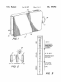
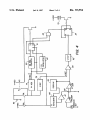

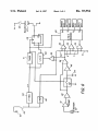


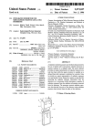

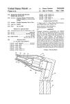
![T] .1](http://vs1.manualzilla.com/store/data/005831826_1-5c5b79be6c7f2f902c022f1ff12b7474-150x150.png)