1
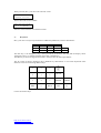
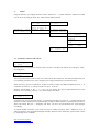
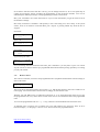
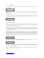
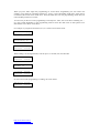
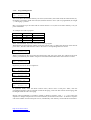
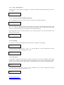
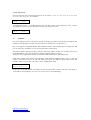
DCC_Gen (v.2D) – User Manual
1.-
Introduction
DCC_Gen is a simple DCC Command Station with PC communication (Lenz Xbus v.3.0 protocol) and
speed control by potentiometer.
It can control locomotives equipped with DCC decoder in addresses 1 to 99. There is an address 00
analog loco available. This allows control of a conventional (non DCC) loco by the 'stretched zeros'
method, not advised for ironless rotor motors (Escap, Faulhaber, Minimotor etc). In analog mode, the
waveform is similar to a conventional PWM but is a bit noisy and is not recommended for a long time
use. Use only DCC locos if you can
Supports 14, 28 y 128 speed steps, functions FL and F1 to F8 for locomotives, up to 99 turnouts and 128
feedback inputs with S88 modules. You can establish up to 26 different routes, for it there are up to 254
turnout memories.
Additionally it can be controlled by RC5 type TV remote (Philips, Daewoo ...)
It can program DCC decoders in Direct, Paged, Register and PoM modes. With an auxiliary circuit it can
read DCC decoders in Direct, Paged and Register modes.
It only need a PIC 16F876 working at 8MHz, a 16 keys keyboard and two pushbuttons for Emergency
Stop and Menu Select function in a LCD display (2 lines of 16 characters), and IR receiver, a
potentiometer, one MAX232 driver and inverters.
2.- Connecting DCC_Gen
DCC_Gen works between 9V and 16V in DC or AC, (it internally has a rectifier and one 5V voltage
regulator) in power connector.
X3:
1: 9..16V
2: 9..16V
DCC signal for booster is in another connector.
X2:
1: GND
2: DCC Data (5V)
Potentiometer connector:
JP6:
1: +5V
2: cursor
3: GND
Auxiliary circuit ACK detector input (for reading CV) over programming track:
JP7:
1: ACK
2: GND
3: +5V
DB9 female connector for PC communication using Xbus / Lenz XpressNet v.3 protocol, and only uses 4
signals:
JP5:
2: TXD
3: RXD
5: GND
8: CTS
The last connector is for S88 feedback modules, verify pin order before connecting.
JP4:
1: +5V
2: Reset
3: Load
4: Clock
5: GND
6: Data in
http://www.fut.es/~fmco
http://usuaris.tinet.org/fmco
When powered, DCC_Gen shows the welcome screen:
DCC-Gen
Command Station
Then it shows the version number:
Ver: 2D 12/03/05
By F.M.CAÑADA
After this it will show the Loco Selection menu.
2.-
Keyboard
DCC_Gen uses a 16 keys keyboard and two additional pushbuttons, with this distribution:
7
4
1
<
8
5
2
0
9
6
3
>
ENT
UP
DWN
FNC
STP
SEL
The STP key is the Emergency Stop, when pressed all locomotives will stop and the display shows
‘Emergency Stop!’ to continue operation press STP or the SEL key.
The SEL key is used to change between menus. All keys have the auto repeat feature.
The TV remote is like the keyboard, due to different keys distribution on TV remote keyboards some
functions can be accessed using different keys:
7
8
9
OK
TXT
VOL+
I-II
4
5
6
YELLOW
1
2
3
V
GREEN
STDBY
<
RED
0
>
BLUE
MUTE
VOL-
MENU
P+
^
Colours are teletext keys.
http://www.fut.es/~fmco
http://usuaris.tinet.org/fmco
3.-
Menus
Using the SEL key you change the menu, when a menu has a ‘>’ symbol indicates a submenu to which
you can access pressing the ‘ENT’ key. These are the different menus.
Feedback: 65-66
1-3----8-2----7-
Mikado
12:35
03: <000 14 *………
Routes
12:35
Play. A-001: 01/
Service Mode
>
Select Loco: 03
03: <000 14 *………
CV Direct Pag/Rg
0001-000 001-00
Parameters >
Loco
Name
03 14 Mikado
Language:
English
DC Speed:
Slow
Hour
Scale
12:35
24:1
Routes free: 254
Rec. A-001: 01/
3.1.- Locomotive selection and control
Select Loco: ---: STOP 128 *………
Initially there is no locomotive selected, enter locomotive number with numeric keys and press ‘ENT’.
For example 03:
Mikado
03: >000
14
12:45
-………
The screen shows the locomotive bane, the current time in the scaled time, second line indicates that you
are controlling locomotive 03, now is stopped, uses 14 steps and it haven’t any function active.
With ‘FNC’ key you turn on and off FL, usually locomotive’s light. For additional functions press ‘1’, to
control the F1 function, ‘2’ controls F2 and so on up to ‘8’ for F8.
With the potentiometer or the ‘<’ y ‘>’ keys you can change the current speed and direction of the
locomotive. For example, pressing ‘>’ key twice and pressing ‘FNC’:
Select Loco: 03
03:>>002 14 *………
Locomotive 03, moving forward, speed 2, 14 speed steps and light on. The first ‘>’ symbol indicates the
direction towards you have to move potentiometer to match current speed for controlling the locomotive,
when both match, the first ‘>’ disappear and when you move the potentiometer the speed changes
accordingly.
To control another locomotive, press ‘ENT’ key type its number and press ‘ENT’. Address 00 is for an
analog locomotive (not equipped with digital decoder), functions aren’t functional. (speed control is done
by ‘stretching zeroes’ method).
http://www.fut.es/~fmco
http://usuaris.tinet.org/fmco
In locomotive selection menu with the ‘UP’ key you can change between 14, 28 or 128 speed steps to
control the locomotive. Select according the programming of the locomotive decoder. You can set
individually the default speed steps in the programming locomotive name menu.
DCC_Gen ‘remembers’ the 16 last entered locos, if you re-enter the number you get the values it has at
the moment of change.
How many locomotives ‘remember‘ and specially if one is the analog loco, more slowly is the system
answer, if one is not used we can do that DCC_Gen ‘forgets’ it pressing ‘DWN’ key when the loco is
stopped.
Press ENT:
Select Loco: 03
03: >000 14 *………
Press ‘UP’
Select Loco: 03
03: >000 28 *………
Press DWN:
Select Loco: 03
--: STOP 128 -………
Type 00 and press ENT:
Analog
00: >000
14
12:45
-………
For a fast change between locomotives that DCC_Gen ‘remembers’ you only have to press ‘UP’ and to
stop the current locomotive with his pre-programmed deceleration without pressing speed keys or rotating
pot just push ‘DWN’.
3.2.-
Route Control
The control of turnouts, accessories and programmed routes (sequential and automatic turnout change) is
done in this menu:
Routes
12:35
Play A-001: 04/
The screen shows the playing mode, current route is ‘A’, and the first turnout in the route is number 4 set
to diverging. You can also see the current time accordingly to selected time scale.
With the ‘UP’ and ‘DWN’ keys we change the route from ‘A’ to ‘Z’ and pressing the ‘ENT’ key we play
the programmed route, every short time a turnout of the route is moved until the end of the programmed
route.
To revise the programmed route use ‘<’ y ‘>’ keys, when 00 is showed indicates the end of the route.
To manually move a turnout, type its number (01 to 99) with numeric keys and press ‘FNC’ to move
between straight ‘|’ or diverging ‘/’ and vice versa. This not erases the programmed route.
http://www.fut.es/~fmco
http://usuaris.tinet.org/fmco
3.3.-
Service Mode
To enter Service mode to program decoders, record of routes and change DCC_Gen parameters press
‘ENT’ in this menu:
Service Mode
>
When entering Service Mode, all locos will stop, when exiting Service Mode all locos have its speed set
to zero.
When programming CV, all loco in the layout will be programmed, so before programming left only one
loco in the layout.
In this menu, if you press FNC the screen will show the feedback status, you can continue controlling the
loco but the UP y DWN keys now select the different S88 modules. Pressing SEL key you return to
Service Mode selection menu.
Feedback: 65-66
1-3----8-2----7-
3.3.1.- CV Programming
With DCC_Gen you can program all the CV range (1 to 1024) in four different modes (Direct, Paged,
Physical and PoM). The programming have to be done with only ONE locomotive on the track, if not all
locomotives get the same programming data.
With an auxiliary circuit you get an programming track output in which you can also read the CV in
Direct, Paged y Physical modes (if you don’t connect the auxiliary circuit place an 10K resistor between
pins 1 and 2 of JP7). CV reading is only possible in programming track, writing CV can be done on
programming or main track.
When you put a locomotive in the programming track and enter Service Mode (locomotive must be
stopped and light and functions off) the auxiliary circuit LED must remain off, when programming a CV
the LED must light on when the loco makes a ‘click’. If the potentiometer is correctly adjusted and occurs
the things as described, when reading a CV depending on read mode (Direct, Paged) the LED lights some
times during reading. Check when you read a know CV (CV1, CV7, CV8 for example) the data readed is
correct.
CV ----0001-000
Pag/Rg
001-00
Not all the decoders supports all programming modes, select the convenient with keys ‘1’ to ‘4’ (1:Direct,
2: Paged, 3:Physical, 4:PoM). For example, when you press ‘2’:
CV Paged
0001-000
Pag/Rg
001-00
With ‘UP’ y ‘DWN’ keys select the CV to modify, on the right shows the corresponding page/register.
For a fast access to decoder accessory CV (513 and above) is possible to decrement with ‘DWN’ after
selecting CV1, then it shows CV512.
With ‘<’ y ‘>’ keys select the value to program between 0 to 255 for the selected CV, read the manual of
your decoder for the range an mode to use.
http://www.fut.es/~fmco
http://usuaris.tinet.org/fmco
When you press ‘ENT’ begin the programming, he screen shows 'Programming CV', the LED in the
auxiliary circuit lights for a moment and the loco ‘clicks’, is the acknowledge ACK pulse. If the pulse is
not detected, the screen shows 'ACK Error'. Some decoders don’t use new programming values until you
retire and then put the loco on track.
To read a CV put the loco in the programming track and press 'FNC', the screen shows ‘Reading CV…’
in a few seconds depending on the programming mode it shows the read value. If ACK pulses aren’t
detected the screen shows ‘ACK Error’.
For example, to program acceleration (CV3) to a value of 10 in Direct mode:
CV Direct Pag/Rg
0003-010 001-02
CV Direct Pag/Rg
Programming CV..
CV Direct Pag/Rg
0003-010 001-02
When reading CV8 in Paged mode (it can last up to 15 seconds) of a Lenz decoder:
CV Paged
0008-000
Pag/Rg
002-03
CV Paged Pag/Rg
Reading CV…
CV Paged
0008-099
Pag/Rg
002-03
In case of error when programming or reading, the screen shows:
ACK Error Pag/Rg
0008-000 002-03
http://www.fut.es/~fmco
http://usuaris.tinet.org/fmco
3.3.2.- Programming Routes
Routes free: 254
Rec
A-001: 00/
The screen shows the available memory for routes (254 turnouts), the record mode, the selected route (A),
the number of sequence inside the route (001) and the turnout to move (00: not programmed) to straight
‘|’ or diverging’/’ position.
DCC_Gen supports up to 26 routes and can control turnouts 1 to 99, this are record in memory even you
power off the unit.
An example of a route to program:
Sequence
1
2
3
4
Turnout
02
05
04
11
Direction
/
/
|
/
With ‘UP’and ‘DWN’ keys select the route (A to Z) to program.
With numeric keypad enter the number of the first turnout (02), to change the direction of the turnout
press ‘FNC’, this also sends the DCC order to the track so corresponding turnout is moved.
Routes Free: 254
Rec
A-001: 02/
When is positioned on the correct direction (diverging in this case) press ‘ENT’ key and will be saved in
memory, automatically the number of sequence is incremented and decrements the routes free counter:
Routes Free: 253
Rec
A-002: 00/
Repeat the process for the next sequences:
Routes Free: 253
Rec
A-002: 05/
Routes Free: 252
Rec
A-003: 04|
Routes Free: 251
Rec A-004: 11/
Routes Free: 250
Rec
A-005: 00/
In operations mode, select the Route Control menu, choose route A and press ‘ENT’, then the
programmed sequence will be executed: turnout 02 diverging, a few time after turnout 05 diverging, then
04 straight and at the end 11 diverging.
During route programming is possible to modify or delete a sequence, with ‘<’ y ‘>’ keys select the
sequence to change and press the new turnout number, the direction and ‘ENT’. To delete a sequence
enter 00 as number of turnout and press ‘ENT’, automatically route memory counter Hill be incremented.
http://www.fut.es/~fmco
http://usuaris.tinet.org/fmco
3.3.3.- DCC_Gen Parameters
To modify DCC_Gen parameters: Language, Loco names, scaled clock and DC speed mode, press ‘ENT’
in this menu:
Parameters
>
3.3.3.1.- Locomotive Names and default speed steps
You can change the name of the current locomotive selected or its default speed steps:
Loco
Name
03 128 Mikado
The menu shows the currently locomotive select name (up to 9 letters) and the default speed steps. With
the ‘<’ y ‘>’ keys you can move the cursor and with UP y DWN keys you can select other letter for the
current cursor position, when you press ENT it will be saved into memory.
By pressing FNC key you can select between 14, 28 y 128 speed steps. To save the new selections into
memory just press ENT.
Loco
Name
03 128 Big Boy
3.3.3.2.- Language
It’s possible to change the language of the menus between ‘Castellano’ and ‘English’.
Language:
English
To change between languages press ‘<’ and ‘>’ or ‘UP’ and ‘DWN’, to select it permanently even after
power off, when you select the language press ‘ENT’.
Idioma:
Castellano
3.3.3.3.- DC Speed
It’s possible to change the mode that DC voltage is generated for loco 00 (not equipped with decoder)
between ‘Slow’ and ‘Fast’ in first mode speed is increased slowly on first steps, on the second increments
are faster (Not all engines works equally and is not recommended to run a locomotive without decoder)
DC Speed:
Slow
To change between modes press ‘<’ and ‘>’ or ‘UP’ and DWN’ keys, to select it permanently even after
power off, when you select the mode press ‘ENT’.
DC Speed:
Fast
http://www.fut.es/~fmco
http://usuaris.tinet.org/fmco
3.3.3.4.- Fast Clock
You can select the fast clock scale between one of 16 values: 1:1, 2:1, 3:1, 4:1, 5:1, 6:1, 7:1, 8:1, 10:1,
12:1, 15:1, 20:1, 24:1, 30:1, 40:1 and 60:1.
Hour
12:35
Scale
24:1
To change hours press ‘<’, to change minutes press ‘UP’ and to select a scale value press ‘FNC’, to select
it permanently even after power off, when you select the scale press ‘ENT’.
Hour
14:50
4.-
Scale
60:1
Feedback
For a full computer control of the layout, besides controlling locomotives and turnouts and signals, the
computer need information of where are the locomotives (which track is occupied, etc,...).
DCC_Gen supports compatible Märklin S88 feedback modules, these modules have 16 inputs each and
you can chain up to 8 modules, so you can verify the status of 128 inputs.
The nearest module connected to DCC_Gen have the lowest address, in this case 65 and 66 (in Lenz is
the default address, it only uses 8 inputs per module and the S88 have 16 inputs).
Verify the correct signal order when you connect the cable between DCC_Gen and the S88.
Inside Service mode select menu if you press ENT it will show the feedback status screen, you also can
control a locomotiva but now the UP and DWN keys shows the different inputs status of the S88
modules. When you press SEL you return to Service Mode select menu.
Feedback: 65-66
1-3----8-2----7In this case, in the S88 module with address 65 and 66, (the nearest to DCC_Gen) are active inputs 1,
3,8,10 and 15 corresponding to 65.1, 65.3, 65.8, 66.2 y 66.7 in Lenz addressing.
http://www.fut.es/~fmco
http://usuaris.tinet.org/fmco
5.- Computer connection
The connection between DCC_Gen and PC is done in the connector DB9F in 9600 bauds, 8 data bits, 1
stop bit, no parity and hardware flow control CTS.
The flow control permits to stop data communication from PC, the RTS signal from computer isn’t
observed. It only uses four connection cables, but all wires are connected in the correct form like a
modem so you have to use a standard modem connection cable.
DCC_Gen implements a wide variety of Lenz Xbus v.3, v.2 and v.1 commands, some characteristics to
be observed are:
- Locomotives address range only between 1 to 99 (with v.3 commands: AH=0)
- Supported CV programming modes are Paged, Direct y Physical but only for CV 1 to 256, this is a
v.3 limit. To program the full range (1 to 1024) use PoM mode if your decoder have support or
manually in DCC_Gen menu that supports the full range for all modes.
- Everything Off is not supported because DCC_Gen can disconnect the booster, it generates the
Emergency Stop effect.
- Requesting feedback out of the range of the S88 (65 to 80) returns accessory without feedback (this
includes turnouts).
- Emergency stop of all locomotives only affects that DCC_Gen ‘remembers’.
- Emergency stop for selected locomotives (v.1 and v.2) only is possible for one and must be one
‘remembered’ by DCC_Gen.
- Double Head and Multiunit aren’t supported. If your decoder supports CV19, you can program it and
use multiunit.
For complete information of the Xbus and XpressNet visit Lenz web.
5.1.- Xbus / XpressNet in DCC_Gen
The Xbus / XpressNet protocol transfer information by data packets, every data packet has a header byte,
data bytes and control byte that is a XOR operation of all the precedent bytes.
Header byte is made in to halves, high nibble has the function to do and the low nibble is the number of
data bytes not including header byte or control byte. All bytes are in hex notation in the following
command description.
Every time the computer sends a command it has an answer: the solicited data or a message send by
LI100. Really with Xbus isn’t possible to know if a order arrives to the track, a correct command answer
(01,04,05) only mind that arrives to command station. An answer of unknown command (61,82,E3) mind
that the order isn’t supported by DCC_Gen. An answer of Interface Error (01,01,00) mind that the send
command hasn’t got the correct control byte.
In every moment computer can receive an unsolicited answer, It must be consider if you write your own
program, the answers of this type are::
- BC Normal Operations Resumed (when entering Operations mode)
- BC Everything Off
- BC Everything Stopped
- BC Service mode entry (when entering service mode)
- BC Feedback (when a change is made in a feedback input or when you change a turnout with
keypad)
Locomotive operated by another device (no supported completely by DCC_Gen)
- Double Header occupied (no supported by DCC_Gen)
http://www.fut.es/~fmco
http://usuaris.tinet.org/fmco
5.1.1.- LI100 Messages
The answers to commands that DCC_Gen can send wich are generated by LI100 interface.
Header
01
01
01
Data
01
02
04
Xor
00
03
05
Answer description
Error interface. Control byte was erroneous
Timeout. No answer from command station.
The command was correct
If computer sends the request to obtain the version of the LI100 interface:
Header
F0
Xor
F0
Command description
LI100 version info request
You get this answer:
Header
02
Data
30 01
Xor
33
Answer description
Hardware ver. 3.0, software ver. 0.1
5.1.2.- BC Messages
These messages are sent by command station to all Xbus devices without a specific request:
BC Normal Operations Resumed
Header Data
Xor
Description
61
01
60
Entering Operations mode
BC Everything Off
Header Data
61
00
Xor
61
Description
All off. DCC_Gen generates Everything Stopped too
BC Everything Stopped
Header Data
Xor
81
00
81
Description
Emergency stop
BC Service Mode Entry
Header Data
Xor
61
02
63
Description
Entering Service mode
BC Feedback
Header
Data
Xor
Description
40 + n
ADR DAT …
XX
Changes in turnouts or S88 inputs
This command is described in Accessory Decoder Information request
http://www.fut.es/~fmco
http://usuaris.tinet.org/fmco
5.1.3.- Xbus / XpressNet commands supported by DCC_Gen
Commands listed first with computer command and then DCC_Gen answer, if a command is not
supported you’ll get this answer:
Header
61
Data
82
Xor
E3
Answer description
Command not supported
If a command hasn’t specific answer, you’ll get::
Header
01
Data
04
Xor
05
Answer description
Command received correctly
Command Station Software Version
Header
Data
Xor
Command description
21
21
00
Xbus version of DCC_Gen request
Header
63
Data
21 30 00
Xor
72
Answer description
Version 3.0. LZ100 command station
Command Station Status
Header Data
Xor
21
24
05
Command description
Command Station status request
Header
62
Answer description
Status of DCC_Gen
Data
22 SS
Xor
Xx
SS:
Bit 0: En Emergency Off if 1
Bit 1: En Emergency Stop if 1
Bit 2: Start-up mode. Always 0. Locomotives are stopped at DCC_Gen power on
Bit 3: Service mode if 1
Bit 4 a 7: Always 0
Resume Operations Request
Header Data
Xor
Command description
21
81
A0
Enter operations mode request
DCC_Gen enters operations mode and sends answer BC Normal Operations Resumed
Stop Operations Request
Header Data
Xor
Command description
21
80
A1
Stop sending DCC packets
Enters in Emergency stop and sends answer BC Everything Off and then BC Everything Stopped because
DCC_Gen can’t stop booster output.
Stop All Locomotives
Header
Xor
Command description
80
80
Emergency stop
Enters in Emergency stop and sends answer BC Everything Stopped
http://www.fut.es/~fmco
http://usuaris.tinet.org/fmco
Emergency Stop a Locomotive and Emergency Stop selected locomotives (Xbus v.1 y v.2)
Header Data
Xor
Command description
91
NN
Xx
Stop locomotive number NN
DCC_Gen only supports stop one locomotive so, both commands are the same
Emergency Stop a Locomotive (XpressNet v.3)
Header Data
Xor
Command description
92
00 NN
Xx
Stop locomotive number NN
DCC_Gen only supports 99 locomotives: AH=0, AL=NN
Locomotive Information Request (Xbus v.1)
Header Data
Xor
Command description
A1
ADR
Xx
Locomotive Information v.1
This is the Xbus version 1 that only supports 14 speed steps, all are converted to this. Speed 1 is
emergency stop
If locomotive is different than currently controlled by DCC_Gen keyboard you get this answer:
Header
Data
Xor
Answer description
83
ADR DAT1 DAT2
xx
Current status of the locomotive
ADR: Locomotive number (00 a 63)
DAT1 (0DF0VVVV):
Bit 6 (D): Direction, 1: Forward, 0: Backwards
Bit 5 (F): FL status (usually locomotive’s light)
Bit 0 a 3 (V): Current speed
DAT2 (0000FFFF):
Bit 3: Status F4
Bit 2: Status F3
Bit 1: Status F2
Bit 0: Status F1
If locomotive is currently controlled by DCC_Gen keyboard the header byte will be A3.
Locomotive Information Request (Xbus v.2)
Header
Data
Xor
Command description
A2
ADR MOD
Xx
Locomotive Information v.2
This is the Xbus version 2 that only supports 14, 27 and 28 speed steps, 128 speed steps are converted to
28. Speed 1 is emergency stop
If locomotive is different than currently controlled by DCC_Gen keyboard you get this answer:
Header
Data
Xor
Answer description
84
ADR DAT1 DAT2 MOD
xx
Current status of the locomotive
ADR: Locomotive number (00 a 63)
DAT1 (0DFVVVVV):
Bit 6 (D): Direction, 1: Forward, 0: Backwards
Bit 5 (F): FL status (usually locomotive’s light)
Bit 4: Speed, additional half step. Always 0 for 14 speed steps
Bit 0 a 3 (V): Current speed.
DAT2 (0000FFFF):
Bit 3: Status F4
Bit 2: Status F3
Bit 1: Status F2
Bit 0: Status F1
MOD:
00: 14 steps
01: 27 steps
02: 28 steps
If locomotive is currently controlled by DCC_Gen keyboard the header byte will be A4.
http://www.fut.es/~fmco
http://usuaris.tinet.org/fmco
Locomotive Information Request (XpressNet v.3)
Header
Data
Xor
Command description
E3
00 00 ADR
Xx
Locomotive Information v.3
This is the Xbus version 3 that supports 14, 27, 28 and 128 speed steps. Speed 1 is emergency stop.
DCC_Gen only supports 99 locomotives: AH=0, AL=ADR if you send a greater value you get
Timeout.error
You get the answer:
Header
Data
E4
ID SPD FNA 00
ID (0000BFFF):
Bit 3 (B):
Bit 0 a 2 (F):
SPD (RVVVVVVV):
Bit 7 (R):
Bit 0 a 6 (V):
Xor
xx
Answer description
Current status of the locomotive
Status, 0: Free Locomotive, 1: Locomotive controlled by other device
Speed steps, 0: 14 steps, 1: 27 steps, 2: 28 steps, 4: 128 steps
Direction, 1: Forward, 0: Backwards
Current speed (0: stop, 1: emergency stop)
14 steps:
0 to 15
27, 28 steps:
Bit 0 to 3: speed from 0 to 15, Bit 4: additional half step
128 steps:
0 to 127
FNA (000FFFFF):
Bit 4: Status FL
Bit 3: Status F4
Bit 2: Status F3
Bit 1: Status F2
Bit 0: Status F1
Locomotive Operations (Xbus v.1)
Header
Data
Xor
Command description
B3
ADR DAT1 DAT2
Xx
Locomotive control in 14 steps
This is the Xbus version 1 that only supports 14 speed steps; values are the same in Locomotive
information request (v.1). From now locomotive will be controlled in 14 steps.
Locomotive Operations (Xbus v.2)
Header
Data
Xor
Command description
B3
ADR DAT1 DAT2 MOD
Xx
Locomotive control in 14, 27 and 28 steps
This is the Xbus version 2 that only supports 14, 27 and 28 speed steps, values are the same in
Locomotive information request (v.2). From now locomotive will be controlled in specified steps.
Locomotive Speed and Direction Operations (XpressNet v.3)
Header
Data
Xor
Command description
E4
10+n 00 ADR SPD
Xx
Locomotive control in 14,27,28 and 128 steps
This is the Xbus version 3 that supports 14, 27, 28 and 128 speed steps, speed values are the same in
Locomotive information request (v.3). From now locomotive will be controlled in specified steps.
n:
0: 14 steps
1: 27 steps (hill use 28 steps but without maximum speed)
2: 28 steps
3: 128 steps
Locomotive Function Operations (XpressNet v.3)
Header
Data
Xor
Command description
E4
20 00 ADR FNA
xx
Locomotive function operation
This is the Xbus version 3 because function are controlled separately, function values are the same in
Locomotive information request (v.3)
http://www.fut.es/~fmco
http://usuaris.tinet.org/fmco
Accesory Decoder information request
Header
Data
Xor
42
ADR 80+n
xx
Command description
Accessory decoder Status
This command gives as answer the status of four inputs
ADR: For accessory (turnouts): Output number divided by 4.
(DCC_Gen returns always accessory without information)
For feedback:
Module number.
n:
High Nibble if 1, Low Nibble if 0
Xbus start to number accessories from 0, so for the first tour inputs of the first S88 the ADR byte is 40
and n equal to 0, for turnouts 1 and 2, ADR byte is 00 and n equal to 0.
Header
Data
Xor
Answer description
42
ADR DAT
xx
Accessory decoder Current Status
ADR:
For accessory (turnouts): Turnout number divided by 4.
(DCC_Gen always returns accessory without information for a request
and status if operated by keyboard)
For feedback:
Module number.
DAT (0TTNZZZZ):
Bit 5,6: 00: Accessory without information (DCC_Gen returns for turnouts)
01: Accessory with information (not supported)
10: Feedback module
Bit 4: High Nibble if 1, Low Nibble if 0
Bit 0..3: Input Status
BC Feedback
Header
40+n
Data
ADR DAT ….
Xor
xx
Answer description
Accessory decoder Current Status
If one or more S88 inputs change DCC_Gen generates this unsolicited answer. Minimum one pair
ADR/DAT and maximum 7 pairs are sent so n is the number of data bytes as described in Accessory
Decoder Information containing the status of inputs that changes.
Accesory Decoder Operation
Header
Data
52
ADR 80+n
Xor
xx
Command description
Accessory operation
ADR: Only for accessories turnouts):
Turnout number divided by 4.
N (DBBB):
Bit 3: Activate if 1 o Deactivate if 0.
Bit 0..2: Output number. There are 8 outputs for 4 turnout control in 2 positions.
Operations Byte Mode Programming (PoM) (XpressNet v.3)
Header
Data
Xor
Command description
E6
30 00 ADR EC+n CV DAT
Xx
PoM CV Programming
CV Programming in operations mode, this is the unique mode that supports 1024 CV.
ADR:
n:
CV:
DAT:
Locomotive’s number
CV Address (bits 8 and 9)
CV Address (bits 0 to 7) It can be CV1 (CV starts in 0, CV1=0)
Data to program in the CV
http://www.fut.es/~fmco
http://usuaris.tinet.org/fmco
Operations Bit Mode Programming (PoM) (XpressNet v.3)
Header
Data
Xor
Command description
E6
30 00 ADR 7C+n CV F0+b
Xx
PoM CV bit Programming
CV Programming in operations mode, , this is the unique mode that supports 1024 CV and individual bits
programming.
ADR:
n:
CV:
b:
Locomotive’s number
CV Address (bits 8 and 9)
CV Address (bits 0 to 7) It can be CV1 (CV starts in 0, CV1=0)
Bit 3: bit value
Bit 0 a 2: Bit to program
With the following CV programming commands DCC_Gen enters in Service mode, and does the
programming or reading but you have to request specifically the result of the operation with Service
Mode Results. To exit Service mode you have to send Resume Operations. CV starts in 1 (CV256=0).
Register mode only permits CV from 01 to 08.
Header
Data
22
11 CV
23
12 CV DAT
22
15 CV
23
16 CV DAT
22
14 CV
23
17 CV DAT
CV:
CV Number
DAT: Data to program
Xor
xx
xx
xx
xx
xx
xx
Command description
Register mode reading (Physical)
Register mode programming (Physical)
Direct mode reading
Direct mode programming
Paged mode reading
Paged mode programming
DCC_Gen enters in Service mode, to obtain the data value send this command:
Service Mode Results
Header Data
Xor
21
10
31
Command description
Last CV read results
If was a Paged o Register mode read request you get this answer:
Header
Data
Xor
Command description
63
10 CV DAT
xx
Paged or Register mode result
CV:
CV Number
DAT: Data read
If was a Direct mode read request you get this answer:
Header
Data
Xor
Command description
63
14 CV DAT
xx
Direct mode results
CV:
CV Number
DAT: Data read
If the read was unsuccessful (ACK pulse not received), DCC_Gen sends data not found error:
Header Data
Xor
Answer description
61
13
72
data not found error
Sorry for any mistakes in translation!
Paco
http://www.fut.es/~fmco
http://usuaris.tinet.org/fmco
Annex I. DCC_Gen628
If you build Robert Cote command station (MiniDCC) and you want to prove the working mode of
DCC_Gen before build it, you can program PIC16F628 of MiniDCC with the code DCC_Gen628.
The keyboard has identically distribution and works identically, but memory is smaller so some things
aren’t implemented (languages, analog locomotive, names, potentiometer, infrared, PC connection)
7
4
1
<
8
5
2
0
9
6
3
>
ENT
UP
DWN
FNC
STP
SEL
The menu is simpler:
Select Loco: 03
03: <000 14 *---Loco
12:35
03: <000 14 *---Route
12:35
Play A-001: 01/
Service Mode >
CV Direct Pag/Rg
0001-000 001-00
Hour
Scale
12:35
24:1
Routes free: 254
Rec
A-001: 01/
Revisions:
08/02/2002. After discover and build MiniDCC, a booster with L298, a decoder with PIC12C508 and
MERG accessory decoder, I need to control an analog loco and connect it to a computer. I
think in expand MiniDCC and make an DCC data generator (DCC_Gen) by interrupts to
control analog loco with DCC signal, I change to PIC16F876 to get more memory and
added computer communication (Xbus v2.3), the stack, two languages, routes, feedback, ...
07/04/2003. I added a fast clock after reading an article about an interesting mode to play trains, making
timetables, routes, etc.
01/09/2004. I saw IRIS command and I thought in use TV remote as a throttle.
08/16/2004. After start my web (http://www.fut.es/~fmco/) and with the received commentaries I added
a potentiometer to control locos and updated communication protocol to Lenz Xbus v.3.
03/12/2005. After designing an auxiliary circuit to detect ACK pulses in any booster, I updated
DCC_Gen code to version 2C that permits CV reading and corrects some errors with PC
communication.
04/28/2005. Seeing command station trends I added locomotives names and at last functions F5 to F8
that resist me.
http://www.fut.es/~fmco
http://usuaris.tinet.org/fmco