1
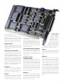
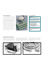
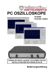
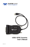
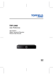
Data Acquisition, Controlling and Steering with PCs
Multi-LAB/2
®
Intelligent Low-Cost PC Board
1
Multi-LAB
2
Intelligent Low-Cost PC Board
Apart from many analog and digital inputs and
outputs, this board contains – like all SORCUS
boards – a processor of its own (’86-compatible). Thus, parallel processing to the PC is
possible. This is important especially for modern PC operating systems like Windows and
OS/2 in order to achieve real-time capability.
Data acquisition, controlling and steering can
be run on the board without any interaction
with the PC. The PC can perform other tasks,
e. g. the graphical display of acquired data.
The local RAM on the board can buffer the
data until the PC is ready to process them
and store them on disk. The board itself is
run by a real-time multi-tasking operating
system called OsX (the same as on the MO-
DULAR-4/486 boards). Thanks to the latest
gate array technology, it was possible to put
all this on a short PC board. In addition,
switches and jumpers could be banished from
the board as well as adjustment
potentiometers. All settings on the board are
carried out by software.
The board is available in four versions: MultiLAB/2a, /2d, /2i and /2h. Even though MultiLAB/2i and /2h have the same number of
inputs and outputs as the other versions, they
offer a higher processing speed of the local
CPU, a larger RAM, more analog input and
output ranges, a faster A/D-converter and
extended digital measuring capabilities, e. g.
Special Features
■ Intelligent PC board with
its own CPU and memory
■ Parallel processing to the PC
■ Real-time multi-tasking
operating system on board
■ 16 analog inputs
(12 Bits resolution)
■ 2 analog outputs
(12 Bits resolution)
TD
RD
AIN-0
Analog
Inputs
(12 Bits)
RS-232
Interface
through
AIN-15
RAM
■ 8 digital power outputs,
1 LED
■ 1 timer, 1 universal
measuring channel (e. g. for
Switch for
Card No.
NMI
DATA
IRQ
DRQ
DAK
Analog
Outputs
(12 Bits)
PC
Interface
I
AOUT-OU
AOUT-1U
AOUT-OI
AOUT-1I
incremental encoder)
■ 16 digital inputs
■ RS-232-interface for
remote debugging
CPU
x86
Digital
Outputs
Reset
EEPROM
U
VINA
VINB
OP-0
■ Drivers for DOS,
through
Windows 3.1, Windows 95,
OP-7
Windows NT and OS/2
■ Borland development
InterruptController
Digital
Inputs
IP-0
environment can be used
through
(C++, Pascal)
IP-15
LED
LED
■ No jumpers or
+ 12 V
– 12 V
Watchdog
2
Timer-A
Timer-B/Counter
Incremental Encoder Interface
adjustment potentiometers
■ Short PC board
+5V
GND
■ Low-cost solution
for incremental encoders. In the mode ”Transientenrecorder“ with pre- and post-trigger, a
sampling rate of up to 330 kHz can be
achieved. The following description refers to
Multi-LAB/2h. Please find the differences
between the versions in the specifications.
Standard Software
Multi-LAB/2 is fully supported by the current
standard software packages for data acquisition and control, such as ARGUS, DIAdem
and DIA/DAGO.
Developing Your Own Programs
The user can write his/her own real-time
programs, which run on the board, e. g. with
the help of the Borland development environment for Turbo-Pascal and Borland C++. The
Turbo-Debugger incl. remote debugging can
be used as well. The board is largely compatible with the MODULAR-4/486 board series.
For application programs and data, about 450
KBytes are at the user’s disposal. For the development of PC programs, libraries for Pascal and C++ come with the board.
PC Interface
The board occupies 8 PC I/O addresses. It
can use the PC’s interrupt and DMA channels,
everything is configured by software. Several
boards can use the same PC interrupt.
Counters/Timers
to configure e. g.
10 single-ended and 3 differential
channels dynamically. What is also controlled by software is the dynamic setting of
one of the 16 input ranges for each channel.
As a standard, the inputs have an overvoltage
protection up to 35 Volts, even when the
board is switched off.
Customer-Specific Analog Input Ranges
When using so-called A-Links (these are micro-modules that can be plugged onto the
board), ranges of e. g. 0 to 100 Volts or 4 to
20 mA as well as customer-defined ranges
can be provided.
Automatic Correction
of Analog Input Data
The readings are immediately subjected to a
digital correction regarding gain and offset.
This happens without losing any time by
means of a special hardware multiplier and
adder in the gate array. The correction values
are determined in a correction cycle. During
this process, the settle time of the analog
input part needed after a channel change is
also measured and then always taken into
account automatically.
Analog Out
Analog In
The 16 inputs with a resolution of 12 Bits can
be operated in the single-ended mode or as
differential inputs. The setting is done by
software so that there is also the possibility
For each of the two channels with a resolution
of 12 Bits, two output lines can be used, one
for voltage and one for current. The output
ranges are switched by software. The outputs
have a short-circuit protection.
The two counters/
timers are capable of
generating local interrupts and can thus be
extended as desired.
Channel A can be used as
a timer, channel B can be
operated in other modes as
well, e. g. event counter, incremental encoder interface, and for frequency, pulse width or period measurement.
Digital In
The 16 TTL-compatible digital inputs with
Schmitt trigger characteristic can also be
operated directly in 24-Volt systems (up to 30
Volts).
Digital Out
The 8 digital power outputs can switch
continuously up to 0.6 A each, both as source
and as sink. The maximum switch voltage is
36 Volts. For each group of four channels, it
can be supplied from the outside independently. It is also possible to use the +5 V (for
TTL-compatibility) or the +12 V of the PC,
which are both available at the D-Sub connector. Each output is protected by 2 clamping
diodes against inductive voltage peaks.
Relays, DC-motors and stepping motors can
be connected directly. In case of thermic
overload, the outputs are switched off automatically. They can also be switched off by
software.
3
A-Links for Multi-LAB/2
A-Links are add-on micro-modules that make
it possible to customize the analog input
ranges.
Test Box
Serial Interface
The test box is meant for service purposes.
It is plugged onto the board’s connector and
allows a fully automatic functional test of the
board and all its in- and outputs by means of
a PC program included in the delivery. With
highly precise reference voltages, correction
values are determined, which are written
automatically into the local EEPROM on the
board.
For debugging the real-time programs, the
Multi-LAB/2i and /2h boards are equipped with
a simple serial RS-232-interface. Just link the
Multi-LAB/2 board and the PC via a null-modem cable and test and debug your programs
with the Borland Turbo-debugger.
The Multi-LAB/2i and /2h boards can carry two
A-Links, each of which determines the input
ranges for 8 analog inputs. The A-Links are
independent of each other so a board can be
operated with only one or with two different
A-Links. One A-Link influences the inputs 0
to 3 and 8 to 11, the other one, the inputs 4
to 7 and 12 to 15. This organization is required
because both inputs of a differential channel
are changed by the same A-Link. The tables
below show which A-Links are currently available. Customer-specific A-Links with other
input ranges are possible, too.
Please note that the settling characteristics
of the Multi-LAB/2 board differ when A-Links
are used for voltage inputs. The settle time
depends on the type of the A-Link used (see
table ‘A-Links for Voltage Inputs’).
The Multi-LAB/2 delivery
includes:
■
PC board Multi-LAB/2h,
/2i, /2d, or /2a
■
User manual
(English or German)
■
78-pin male connector with
solder contacts, fitting into
the female connector of
the board
■
■
PC libraries and drivers for
DOS, Windows and OS/2
■
On-board library for Borland Pascal and Borland C++
■
Remote-debugging kernel
for Borland TurboDebugger
■
4
Real-time multi-tasking
operating system ‘OsX’
PC program for test and
configuration purposes
A-Links for Current Inputs
A-Link
Number/Type
Input
Input
of Inputs
Range
Impedance
4x20i
4/differential
0 to 20 mA
125 Ω
8x20i
8/single-ended
0 to 20 mA
125 Ω
A-Links for Voltage Inputs
Voltage
Input
Max. Input
Settle
Devider
Impedance
Range
Time
8x10U
–
100 kΩ
± 10 V
5 µs
8x20U
1:2
200 kΩ
± 20 V
70 µs
8x40U
1:4
200 kΩ
± 40 V
50 µs
8x100U
1 : 10
200 kΩ
± 100 V
30 µs
A-Link
Specifications Multi-LAB/2
Multi-LAB Version
/2a
/2d
/2i
/2h
Unit
CPU [1], Clock
Memory
EEPROM for initialization and adjustment
8
128
no
8
128
no
10
512
yes
16
512
yes
MHz
KByte
PC Interface:
PC-I/O-address selectable by software (”plug and play“)
PC interrupt channels (channels 3, 5, 9, 10, 11, 12, 15)
PC DMA channels (channels 0, 1, 3)
Interrupt and DMA channel selectable by software
yes
yes
yes
yes
yes
yes
yes
yes
yes
yes
yes
yes
yes
yes
yes
yes
–
–
–
–
0/8
12
±5
no
± 35
> 10
90
10
> 33
16/8
12
± 10
no
± 35
> 10
90
10
> 33
16/8
12
[3]
yes
± 35
> 10
90
2,6
> 71
16/8
12
[3]
yes
± 35
> 10
90
1,6
> 111
–
bit
Volt
–
Volt
MΩ
pF
µs
kHz
–
no
–
no
250
yes
330
yes
kHz
–
no
no
yes
yes
–
2
12
±5
±1
10
10
yes
> 20
2
12
± 10
±1
10
10
yes
> 20
2
12
[4]
±1
10
10
yes
> 31
2
12
[4]
±1
10
10
yes
> 50
–
bit
Volt
LSB
µs
mΩ
–
kHz
Serial debug interface (RS-232 asynchronous, 8 data
bits, 1 start bit, 1 stop bit, no parity; programmable
baud rates: 153600, 38400, 19200, and 9600 baud)
no
no
yes
yes
–
Digital inputs: Number of channels
Input range, max.
Upper threshold, typ.
Lower threshold, typ.
Input impedance, typ.
All inputs can be sampled simultaneously
Min. pulse width for triggering interrupts (IP0, IP1)
16
± 30
1,9
0,9
3,6
yes
100
16
± 30
1,9
0,9
3,6
yes
100
16
± 30
1,9
0,9
3,6
yes
100
16
± 30
1,9
0,9
3,6
yes
100
–
Volt
Volt
Volt
kΩ
–
ns
Timer: Number of channels
Timer-A [5]/Timer-B [5], capable of generating interrupts
Timer-B programmable for:
Timer function, resolution
Counter function, max. frequency
Frequency measurement, max. frequency
Pulse width measurement, resolution
Period duration measurement, resolution
Incremental encoder interface, max. frequency/phase
2
yes
2
yes
2
yes
2
yes
–
–
2
–
–
–
–
–
2
–
–
–
–
–
2
2
2
500
500
1,25
2
3
3
500
500
1,25
µs
MHz
MHz
ns
ns
MHz
Digital outputs [6]: Number of channels
External voltag Ux (min./max.)
Output level [7]:
Low (Ux = 5 V, Io = 20 mA), max.
High (Ux = 5 V, Io = – 20 mA), min.
Low (Ux = 24 V, Io = 0,6 A), typ.
High (Ux = 24 V, Io = – 0,6 A), typ.
Output current, continuous, Low/High, max.
Peak current (non repetitiv, < 100 µs)
Output current (outputs disabled), max.
Clamping voltage:
High (Io = 0,6 A), typ.
Low (Io = – 0,6 A), typ.
Slew rate
(10% und 90% level), typ.
Delay (input to output), pos./neg. slope, typ.
8
5/36
8
5/36
8
5/36
8
5/36
–
Volt
0,8
3,2
1,2
Ux – 1,4
± 0,6
± 1,2
± 0,5
0,8
3,2
1,2
Ux – 1,4
± 0,6
± 1,2
± 0,5
0,8
3,2
1,2
Ux – 1,4
± 0,6
± 1,2
± 0,5
0,8
3,2
1,2
Ux – 1,4
± 0,6
± 1,2
± 0,5
Volt
Volt
Volt
Volt
A
A
mA
Ux +1,3
– 1,3
300
Ux +1,3
– 1,3
300
Ux +1,3
– 1,3
300
Ux +1,3
– 1,3
300
Volt
Volt
ns
800/400
800/400
800/400
800/400
ns
95
15
21
0,9
449
0
0
2,3
570
7
0,2
2,9
604
7
0,2
3,1
mA
mA
mA
W
Analog inputs: number of channels (single-ended/diff. inputs)
Resolution
Input ranges
Sockets provided for A-Links
Overvoltage protection
Input impedance (without A-Link)
Conversion time
Effective sampling rate into lacal RAM
Max. sampling rate using
mode ”Transientenrecorder” [2]
On-board temperature measurement
Automatic correction of
gain and offset errors
Analog outputs: Number of channels
Resolution
Output ranges
Linearity
Settle time for full-scale step, typ.
Output impedance, typ.
Short-circuit protection
Effective output rate from local RAM
Current drain from PC [8]:
+ 5 Volt, typ.
+ 12 Volt, typ.
– 12 Volt, typ.
Total power dissipation, typ. [8]
[1] The CPU is compatible
with 80x86 processors.
[2] The special mode „Transientenrecorder“ measures
continuously into a local ring
buffer (64 KBytes) until an
external or internal trigger
appears. The measurement is
ended after a preprogrammed
time. Pre- and post-trigger
data always amount to 64
KBytes.
[3] There is a choice of 16
input ranges (selection by
software):
Unipolar positive:
0 ... 625 mV, 0 ... 1.25 V, 0 ... 2.5
V, 0 ... 5 V, 0 ... 10 V
Unipolar negative:
0 ... -625 mV, 0 ... -1.25 V,
0 ... -2.5 V, 0 ... -5 V, 0 ... -10 V
Bipolar:
±312.5 mV, ±625 mV, ±1.25 V,
±2.5 V, ±5 V, ±10 V
[4] Each channel provides a
voltage output pin and a current output pin. The following
ranges can be set for each
channel by software:
0 ... 5 V, 0 ... 10 V, ±5 V, ±10 V,
0 ... 20 mA, 4 ... 20 mA.
[5] Timer-A is 12 bits wide,
Timer-B is 16 bits wide. The
length of both timers can be
extended by software.
[6] The maximum power dissipation for a group of 4 channels (OP0, OP1, OP2, and OP3
or OP4, OP5, OP6, and OP7) is
2 W, e.g.(each channel of a
group has a LOW output level):
N = 4 * Io * Uo
(Io = output current in Ampere, Uo = output voltage in
Volts).
[7] The outputs are TTLcompatible if Ux = 5 Volts.
[8] All inputs and outputs
open (not connected).
5
Connection Technology
Connection Units, Cables and Connectors for Multi-LAB/2
Table Boxes
The connection boxes C1 and C2 serve as a
board (except for the LED and the analog
either with BNC sockets and screw terminals
comfortable connection between the Multi-
current outputs of the Multi-LAB/2i and /2h)
(C1) or with banana jacks (C2) for connecting
LAB/2 board and your measurement devices.
are led via a 1.5-m-long shielded round cable
the inputs and outputs.
For this purpose, all inputs and outputs of the
to the connection box, which is provided
Connection Boxes C1 and C2 for Multi-LAB/2
INPUT
DIGITAL IN
CH 0
CH 8
CH 1
CH 9
CH 2
CH 10
CH 3
CH 11
CH 4
CH 12
CH 5
CH 13
CH 6
CH 14
CH 7
CH 15
Connection Box C1
OUTPUT
ANALOG IN
DIGITAL OUT
Dimensions
257 x 168 x 36 mm (length x width x height)
0
1
2
3
4
5
6
7
+12 +5
+
0
1
2
3
8
9
10 11 12 13 14 15
+12 +5
+
4
5
6
7
Cable
shielded round cable with
78-pin D-Sub male connector, length 1.5 m
Inputs
16 analog inputs via BNC connectors
16 digital inputs via two 8-pin screw terminal blocks
ANALOG OUT
Outputs
2 analog voltage outputs via a 4-pin screw terminal block
8 digital outputs via two 8-pin screw terminal blocks
Vo l t a g e
+
+
0
1
Supply voltage for external devices
+5 V, +12 V via screw terminal block
Connection Box C2
INPUT
ANALOG
SE
DI
SE
DIGITAL
DIGITAL
Dimensions
257 x 168 x 36 mm (length x width x height)
0
1
2
3
4
5
6
7
0
1
2
3
4
5
6
7
0
1
2
3
4
5
6
7
0
1
2
3
4
5
6
7
8
9
10
11
12
13
14
15
8
9
10
11
12
13
14
15
Inputs
16 single-ended analog inputs via 32 banana jacks or
8 differential analog inputs via banana jacks
16 digital inputs via 32 banana jacks
OUTPUT
ANALOG
V O LT A G E
DIGITAL
+ 12 V
U1
U2
V O LTA G E
6
+5V
0
1
2
3
4
5
Cable
shielded round cable with
78-pin D-Sub male connector, length 1.5 m
6
7
URef
Outputs
2 analog voltage outputs via 4 banana jacks
8 digital outputs via 18 banana jacks
Supply voltage for external devices
+5 V, +12 V via banana jacks
Screw Terminal Block C3
Screw Terminal Block
At the screw terminal block, you can access
Dimensions
the in- and outputs of the Multi-LAB/2 board
86x71x65 (width x depth x height)
at 50 screw terminals. All of the in- and outConnection cable
puts are at your disposal – except for the LED
shielded round cable from 78-pin to
output and the analog current outputs of
50-pin D-Sub male connector, length 1.5 m
Multi-LAB/2i and /2h. The ground lines of the
analog inputs are tied together. The PC’s
Inputs
16 single-ended analog inputs
supply voltages are not available. The screw
via 17 screw terminals or
terminal block can be mounted onto all kinds
8 differential analog inputs via
of rails that are in accordance with EN 50035
17 screw terminals, 16 digital inputs
(G-rail) and EN 50022 (top-hat rail). The con-
via 17 screw terminals
nection cable is included in the delivery. In
Outputs
contrast to the cables of the table boxes C1
2 analog voltage outputs via 4 screw
and C2, it is not permanently fixed, but plug-
terminals, 8 digital outputs via 12 screw
ged into a 50-pin D-Sub connector.
terminals
Screw Terminal Block C3
Multi-LAB/2 Cables and Connectors
All inputs and outputs of the Multi-LAB/2
fixing screws) comes with the board. You can
other end is open or is provided with a 78-pin
board can be accessed via a 78-pin D-Sub
acquire additional male connectors and ready-
male or female connector. The wires in the
female connector. One male connector with
made cables with the 78-pin male connector
cable are twisted to pairs and, as a whole,
solder contacts (including plastic cover and
for the Multi-LAB/2 board on one end, the
shielded twice.
78-pin male or female connector with plastic coverand fixing screws
78-pin male connector with cable
7
Fax Order Form
Adress of customer
Company
Place, Date
Name/Department
Name in block letters
PO Box/Street
Postal Code/City
Signature/Stamp
Order No.
Order No.
Quant.
Multi-LAB/2 Multi-Function Boards
HM-1487
Multi-LAB/2a incl. manual, 78-pin connector and system software
HM-1514
Multi-LAB/2d incl. manual, 78-pin connector and system software
HM-1488
Multi-LAB/2i incl. manual, 78-pin connector and system software
HM-1713
Multi-LAB/2h incl. manual, 78-pin connector and system software
Total price
Accessories
HM-1571
Test box for Multi-LAB/2 incl. software
K2-4003
Debugging cable for Multi-LAB/2i and Multi-LAB/2h
(3-pin Mini-DIN to 9-pin D-Sub. socket, 1,5 m)
FM-1604
Connection Box C1 with BNC-sockets, screw terminals and cable
FM-1698
Connection Box C2 with banana jacks and cable
FM-1830
Screw-clamp terminal block with screw terminals and cable
for Top-hat-rail mounting (50-pin)
K1-3078
Round cable with 78-pin male connector, one end open, 1.6 m
K2-3078
Round cable with 78-pin male and female connector, 1.6 m
K2-3178
Round cable with 7two 8-pin male connectors, 1.6 m
FM-1605
78-pin connector with solder contacts with hood
FM-1799
78-pin connector with solder contacts with hood
A-Links for Analog Inputs for Multi-LAB/2i and /2h
FM-1526
20 mA, 4 differential channels
FM-1740
20 mA, 8 single-ended channels
FM-1877
10 V max., 8 single-ended or 4 differential channels
FM-1741
20 V max., 8 single-ended or 4 differential channels
FM-1742
40 V max., 8 single-ended or 4 differential channels
FM-1744
100 V max., 8 single-ended or 4 differential channels
Total Amount
Shipping Cost
Your Local Distributor:
Amount of Invoice
Please fill in this order form and fax it or send it
by mail. Prices and technical issues are subject
to change.
SORCUS Computer GmbH, Im Breitspiel 11, D-69126 Heidelberg
Phone ++49-6221-32 06-0, Fax ++49-6221-320 6-66, Internet http://www.sorcus.com
8