1
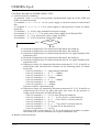
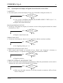
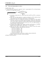
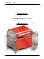
CEBORA S.p.A. 1 TIG 250 AC-DC POWER SOURCE art. 236.76 SERVICE MANUAL 3.302.221 15/01/07 CEBORA S.p.A. 2 CONTENTS 1 - GENERAL INFORMATION.......................................................................................................................... 3 - Introduction. ................................................................................................................................................. 3 - General service policy. ................................................................................................................................. 3 - Safety information. ....................................................................................................................................... 3 - Electromagnetic compatibility...................................................................................................................... 3 2 - SYSTEM DESCRIPTION .............................................................................................................................. 4 2.1 - Introduction. ................................................................................................................................................. 4 2.2 - Technical specifications................................................................................................................................ 4 2.3 - Description of TIG 250 AC/DC power source. ............................................................................................ 4 3 - MAINTENANCE............................................................................................................................................ 7 3.1 - Periodic inspection, cleaning. ....................................................................................................................... 7 3.2 - Operating sequences. .................................................................................................................................... 7 3.2.1 - Control panel commands and signals......................................................................................................... 7 3.2.2 - Power Source TIG operation. .................................................................................................................... 8 3.3 - Troubleshooting.......................................................................................................................................... 10 3.3.1 - The power source does not start, control panel off. ................................................................................. 10 3.3.2 - Power source powered, control panel on, fan (45) stopped. .................................................................... 12 3.3.3 - System powered, display and signals do not show the correct values. .................................................... 13 3.3.4 - The start button produces no effect.......................................................................................................... 15 3.3.5 - In TIG mode, no gas flows from the torch............................................................................................... 16 3.3.6 - In TIG mode, gas flows from the torch, the arc does not strike (no high frequency). ............................. 17 3.3.7 - In open circuit operation, the output voltage is not regular. .................................................................... 19 3.3.8 - In resistive load operation, the output voltage is not regular. .................................................................. 22 3.3.9 - AC operation, arc unstable, welding irregular. ........................................................................................ 24 3.4 - Alarm signals.............................................................................................................................................. 25 3.4.1 - Led (Y) off. Power source output voltage greater than 48 Vac. .............................................................. 25 3.4.2 - Led (F) on. Temperature of the transformer (46) or inductor (50) too high, or low pressure of the coolant fluid. ........................................................................................................................................................ 25 4 - COMPONENTS LIST................................................................................................................................... 26 4.1 - Power source art. 236.76 : see file ESP236.76.pdf enclosed at the end of the manual............................... 26 4.2 - Components table : see file ESP236.76.pdf enclosed at the end of the manual.......................................... 26 4.3 - Spare parts list. ........................................................................................................................................... 26 5 - ELECTRICAL DIAGRAMS ........................................................................................................................ 27 5.1 - Power source art. 236.76 : see file SCHE236.76.pdf enclosed at the end of the manual............................ 27 5.2 - Waveforms. ................................................................................................................................................ 27 5.2.1 - Output voltage with open-circuit power source (par. 3.3.7). ................................................................... 27 5.2.2 - Firing pulses for SCR1 with open-circuit power source (par. 3.3.7). ...................................................... 27 5.2.3 - Firing pulses for SCR2 with open-circuit power source (par. 3.3.7). ...................................................... 27 5.2.4 - Output current with power source loaded in table conditions (par. 3.3.8). .............................................. 28 5.2.5 - Output voltage with power source loaded in table conditions (par. 3.3.8)............................................... 28 5.2.6 - Firing pulses for SCR3 with power source loaded in table conditions (par. 3.3.8).................................. 28 5.3 - Mains filter board (51) code 5.600.993/A. ................................................................................................. 29 5.4 - Fuse board (4) code 5.602.288.................................................................................................................... 29 5.5 - Control board (40) code 5.602.293/A......................................................................................................... 30 5.6 - Shut-off board (48) code 5.602.289............................................................................................................ 31 5.7 - Snubber board (6) code 5.602.294.............................................................................................................. 32 5.8 - HF board (42) code 5.602.290. ................................................................................................................... 32 5.9 - HF-filter board (41) code 5.602.291........................................................................................................... 33 5.10 - Connector board (49) code 5.602.292. ....................................................................................................... 33 5.11 - Diode group (19) code 3.200.090/A. .......................................................................................................... 34 1.1 1.2 1.3 1.4 3.302.221 15/01/07 CEBORA S.p.A. 3 1 - GENERAL INFORMATION 1.1 - Introduction. The purpose of this manual is to train personnel assigned to carry out maintenance on the TIG 250 AC/DC Power Source, art. 236.76. 1.2 - General service policy. It is the responsibility of the customer and/or operator to use the equipment appropriately, in accordance with the instructions in the Instructions Manual, as well as to maintain the equipment and related accessories in good working condition, in compliance with the instructions provided in the Service Manual. Any internal inspection or repairs must be carried out by qualified personnel who are responsible for any intervention on the equipment. It is forbidden to attempt to repair damaged electronic boards or modules; replace them with original Cebora spare parts. 1.3 - Safety information. The safety notes provided in this manual are an integral part of those given in the Instruction Manual. Therefore, before working on the machine, please read the paragraph on safety instructions in the aforementioned manual. Always disconnect the power cord from the mains, before accessing the interior of the equipment. Some internal parts, such as terminals and dissipaters, may be connected to mains or otherwise hazardous potentials. It is therefore forbidden to work with the safety guards removed from the machine unless strictly necessary. In this case, take special precautions such as wearing insulating gloves and footwear, and working in a perfectly dry environment with dry clothing. 1.4 - Electromagnetic compatibility. Please read and observe the instructions provided in the paragraph “Electromagnetic compatibility” of the Instruction Manual. 3.302.221 15/01/07 CEBORA S.p.A. 4 2 - SYSTEM DESCRIPTION 2.1 - Introduction. The TIG 250 AC/DC is un electronic power source suitable for AC/DC TIG welding with high-frequency arc striking. It may be used together with a range of accessories for various types of applications (see list in the Sales catalogue). The operator interface is developed via the control panel built into the power source. 2.2 - Technical specifications. To check the technical specifications, see the plates affixed to the equipment, the Instruction Manual, and the Sales Catalogue. 2.3 - Description of TIG 250 AC/DC power source. The TIG 250 AC/DC is a controlled-current power source, made up of a single-phase transformer and a converter that can be configured as a rectifier bridge for direct current applications, or as a static switch for alternating current applications. The configuration may be selected using the AC/DC selector switch (30)(AF) on the front panel. Referring to the electrical diagram in par. 5.1, drawing 4.1 and table 4.2, one may identify the main blocks that make up the power source. The main switch (15), on the rear panel, directly powers the transformer (46) and the terminal board (52), to which are connected the various internal services of the power source. The power source can operate with either mains at 208 Vac or at 230 Vac, depending on the setting of switch (15). As an effect of the primary circuit of the transformer (46) which acts as an autotransformer, the terminal board (52) and thus all internal services connected to it are always powered at 230 Vac. The mains filter board (51), connected to the terminal board (52), contains the filter to reduce conducted interference reflected in the mains. The transformer (46) has a second power winding, with voltage and current values suitable for welding, and two secondary service circuits; all windings are made up of two half-windings arranged on the two columns of the magnetic core. One 30 Vac service winding powers the circuits for the signals that dialogue outside the power source through the connector board (49). The second service winding a 27 Vac powers the thermal protection circuits of the power source (thermostats on inductor (50) and transformer (46)) and to measure the pressure of the liquid in the cooling unit. The secondary power circuit of the transformer (46) is connected to the current converter, made up of the thyristor group (47) (SCR1 and SCR2), the diode module (19) (D1, D2, D3), the inductor (50) and the AC/DC selector switch (30). The electrical diagram of the power source in par. 5.1 shows the operating table of the AC/DC selector switch (30). Based on the position of the AC/DC selector switch (30), the converter acts as a Halfcontrolled rectifier to generate and regulate direct current, or as static switch to generate and regulate alternating current (in the latter instance the frequency of the alternating output current corresponds to the supply voltage frequency of the power source). The SCR1 and SCR2 (47) receive the driver signals from the control board (40), through the shut-off board (48), and the output current is regulated by the control board (40) by changing the firing angle of SCR1 and SCR2 (47). 3.302.221 15/01/07 CEBORA S.p.A. 5 NOTE In the shut-off board (48) there are two low-powered thyristors, inserted into two similar circuits, one of which is always connected and available, while the other is parallel connected to the first through a relay, when the welding current exceeds approximately 50 Aac. Both are controlled by the same driver signal and thus work simultaneously. Because of this characteristic, in this manual these two thyristors shall be considered as a single one, known as SCR3, “the shut-off thyristor”. SCR3 and the circuits of the shut-off board (48) serve to force SCR2 (47) to shut off during AC operation. This function, simultaneous with the engagement of SCR1 (47), makes it possible to generate the high voltage pulse necessary to perforate the oxidation that forms when welding certain materials (aluminium and similar) and thus makes it possible to maintain the arc when the polarity of the welding current changes. This function repeats during each period of the welding current. Since the value reached by the high voltage depends on the type of oxidation that the material presents, a special circuit of the control board (40) makes sure that this voltage does not reach levels hazardous for operation of the converter. If necessary, it prematurely engages SCR2 (47). In this case welding is poor quality in AC (see par. 3.3.9). At the converter output, on the connection before the “-”output terminal (AB) of the power source, is connected to the HF transformer (28) which, appropriately driven by the HF board (42), generates high voltage and high frequency to strike the arc in TIG welding. Operation of the HF board (42) is dependent upon the presence of 27 Vac alternating voltage on the connector J9, terminals 5 and 6, of control board (40) (HF board (42) power stage power supply) and the HF start command on the connector J9, terminals 7 and 8, of control board (40) (HF relay start command). The connection before the “+”(AC) output terminal of the power source hosts the Hall-effect current transducer (5), which sends to the control board (40) the output current feedback signal, used to regulate the welding current. Near the output terminals of the power source is the HF-filter board (41), which is of primary importance to TIG operation with HF, since it prevents the HF pulse from climbing through the internal circuits of the power source, damaging other parts. Thus, during various maintenance operations, make sure that this board is always firmly connected to the original terminals before activating HF start-up. The mains voltage, again at 230 Vac, to power the service transformer (4) combined with the fuse board (4), is drawn from the terminal board (52). This transformer provides both the supply voltages needed by the various sections of the control board (40) and the synchronization signal of the pulse generators on control board (40). This is why it is important to match the polarity of the connections for both the primary circuit of the service transformer (4) and the secondary synchronization circuit leading to connector J4. The control board (40) is the heart of the power source. It supervises management of the other boards with more specialized functions, regulates the welding current by generating the pulses to send to the thyristors (47). It contains the microprocessor that manages all of the functions of the power source, including those that interface with the user, obtained via the control panel built into the board itself. The signal of the power source output voltage, is drawn from the output terminals of the converter. Appropriately filtered by the snubber board (6), this signal continues toward the control board (42), where it is used to check for any presence of “hazardous voltage” at the power source output (see par. 3.4.1). 3.302.221 15/01/07 CEBORA S.p.A. 6 The snubber board (6) also includes the load resistors for SCR1 and SCR2 (47), which make it possible for SCR1 and SCR2 (47) to function correctly even with an open circuit power source, and the capacitor C1, which helps strike the arc in DC mode. The connector (13) on the rear panel of the power source is connected to the pressure switch on the cooling unit; it is connected in series to the thermostats on transformer (46) and inductor (50), on the same alarm line that reaches the control board (40). When the cooling unit is not connected, it is necessary to make a bridge on connector (13) between terminals 1 and 3, to prevent the power source from remaining blocked. The fan (45), to cool the power elements of the power source, is powered directly by terminal board (52) and therefore always at 230 Vac. On the front panel is the connector board (49), which acts as an interface for the power source input and output signals. It dialogues directly with the control board (40) and contains the filters to eliminate disturbances on the power source input and output signals. These signals include: − Power source start, from torch trigger. − External adjustment of the welding current via external potentiometer. The signals processed by the electronic boards and present at their connectors are listed in the tables in chapter five of this manual. 3.302.221 15/01/07 CEBORA S.p.A. 7 3 - MAINTENANCE WARNINGS ANY INTERNAL INSPECTION OR REPAIRS MUST BE CARRIED OUT BY QUALIFIED PERSONNEL. UNPLUG THE POWER SOURCE FROM THE MAINS BEFORE REMOVING THE PROTECTIVE COVERS AND ACCESSING THE INTERNAL PARTS. 3.1 - Periodic inspection, cleaning. Periodically remove any dirt or dust to ensure smooth air flow, and thus keep the internal elements of the power source cool. Check the conditions of the output terminals, the output and power cables of the power source; replace if damaged. Check the conditions of the internal power connections on the electronic boards; if you find “loose” connections, tighten them or replace the connectors. 3.2 - Operating sequences. The following sequences reflect proper machine operation. They may be used as guidelines for troubleshooting. After each repair, they must be carried out without encountering any error or impediment. 3.2.1 3.302.221 - Control panel commands and signals. 15/01/07 CEBORA S.p.A. 8 NOTE Operations preceded by this symbol refer to operator actions. ♦ Operations preceded by this symbol refer to machine responses that must occur following an operator action. 3.2.2 - Power Source TIG operation. Connect the gas supply to the fitting on the rear panel. Connect the TIG torch to the negative pole (AB) of the power source. Connect the cable of the positive pole (AC) of the power source to the workpiece. Connect the power source to the mains. Close the switch (15) on the rear panel in the position corresponding to the mains voltage. ♦ System powered. ♦ On control panel all leds and display light on (lamp test). ♦ After one second, display (Z) shows the version of the program inserted into control board (40) (es.: P01). ♦ Subsequently, display (Z) indicates the programmed current; the Mode signaling are lit as set before the last time the unit was shut off. Correct? NO (see 3.3.1, 3.3.2, 3.3.3). YES Press the button (E) several times; the “Mode” selection is repeated in sequence. Press the button (P) several times; the “Cicle” selection is repeated in sequence. ♦ Each time the button (E) is pressed, the leds G, H, M and N light in sequence, together with one of leds (F) or (L), that lit alternatively one each other. ♦ Each time the start button (P) is pressed, the leds Q, S, T, R, V, U, W and X light in sequence, according with the “Mode” selected. Correct? NO (see 3.3.3). YES WARNINGS DURING THE FOLLOWING TESTS DO NOT AIM THE TORCH AT PEOPLE OR PARTS OF THE BODY, BUT ONLY TOWARDS AN OPEN SPACE OR THE WORKPIECE. DO NOT TRY TO MEASURE THE OUTPUT VOLTAGE DURING THESE STEPS. THE PRESENCE OF HIGH FREQUENCY MAY DAMAGE THE INSTRUMENT OR THE POWER SOURCE ITSELF. With switch AC/DC (30) select the TIG-DC or TIG-AC process. Use the button (E) to select the TIG-CONTINUOUS with HF, 2-STAGE “Mode”, leds (L) and (G) lit. Briefly press the torch start button. ♦ With switch AC/DC (30) in DC position led (C) remains lit and led (D) off. With switch AC/DC (30) in AC position led (D) remains lit and led (C) off. 3.302.221 15/01/07 CEBORA S.p.A. 9 ♦ Gas begins flowing from the torch, for as long as the button is held down. ♦ Gas continues to flow from the torch for the duration of the post-gas time set, led (X) lit, even after the start button is released. Correct? YES Press the start button and hold it down for approximately 5 seconds. ♦ Gas output begins; the high frequency is then generated to start the arc, as well as the power source output DC voltage (AC voltage is generated only if output current in present). ♦ After approximately three seconds, the output voltage and high frequency are no longer generated (TIG operation stops if there is no current at the power source output after start) and the post-gas stage begins. Correct? NO (see 3.3.6, 3.3.7). YES Use the knob (AA) to set the current based on the welding you intend to perform. Move the torch near the workpiece and press the torch trigger. ♦ Begin welding. Turn the knob (AA) or the torch potentiometer to obtain the current level suitable for the type of welding to be done. ♦ During welding display (Z) indicates the welding current. Correct? NO (see 3.3.3, 3.3.4, 3.3.5). NO (see 3.3.3, 3.3.8). YES Release the torch start button. ♦ The arc shuts off immediately (if long ramp times are not set). ♦ Gas continues to flow for the entire post-gas time. Correct? NO (see 3.3.5). YES REGULAR OPERATION. 3.302.221 15/01/07 CEBORA S.p.A. 10 3.3 - Troubleshooting. WARNINGS ANY INTERNAL INSPECTION OR REPAIRS MUST BE CARRIED OUT BY QUALIFIED PERSONNEL. UNPLUG THE POWER SOURCE FROM THE MAINS BEFORE REMOVING THE PROTECTIVE COVERS AND ACCESSING THE INTERNAL PARTS. NOTE The problems the machine may suffer (symptoms) are indicated in boldface. Operations preceded by this symbol refer to situations that the operator must check into (causes). ♦ Operations preceded by this symbol refer to actions that the operator must carry out to solve problems (solutions). 3.3.1 - The power source does not start, control panel off. MAINS SUITABILITY TEST. No voltage for mains protection. NO Correct? YES ♦ Eliminate any short-circuits or insulation losses on the connections between power cable, switch (15), terminal board (52), transformer (46) primary winding, services transformer (4), fan (45) and socket (12) on rear panel. ♦ Make sure wiring between mains cable, switch (15) and transformer (46) primary winding, with particular care to the connections that perform mains voltage adjustment and between transformer (46) secondary winding and terminals “A” of scr group (47) and “C8” of switch AC/DC (30). If you find damage connections restore them, or devices in short-circuit replace them. ♦ Mains not suitable to power the power source (ex.: insufficient installed power). MAINS CONNECTION TEST. Switch (15), terminals U and W = 230 Vac with both mains at 208 Vac or 230 Vac. YES ♦ ♦ ♦ ♦ 3.302.221 Correct? NO Check power cable and plug and replace if necessary. Make sure wiring between mains cable, switch (15) and transformer (46) primary winding, with particular care to the connections that perform mains voltage adjustment and between transformer (46) secondary winding and terminals “A” of scr group (47) and “C8” of switch AC/DC (30). If you find damage connections restore them, or devices in short-circuit replace them. Check operation of the switch (15), making sure the contacts close in the sequence shown in the table in the electrical diagram of par. 5.1. Check mains voltage conditions. 15/01/07 CEBORA S.p.A. 11 CONTROL BOARD (40) POWER SUPPLY TEST. Control board (40), connector : − J2, terminals 1 and 2 = 16 Vac, pulse generator synchronization signal for SCR1, SCR2 and SCR3 on control board (40). − J3, terminals 2 - 4 - 1 = 16 - 0 - 16 Vac, power supply to internal circuits of control board (40). − J3, terminals 5 - 4 - 6 = 8 - 0 - 8 Vac, power supply to microprocessor circuits on control board (40). − J5, terminals 1 - 2 = 26 Vac, start command circuit power supply. − J6, terminals 4 - 5 - 6 = 7 - 0 - 7 Vac, pulse power source supply for SCR2 and SCR3. − J6, terminals 1 - 2 = 7 Vac, pulse power source supply for SCR1. − J8, terminals 1 - 2 = 30 Vac, protection circuit power supply. YES Correct? NO ♦ Check the wiring between J2 control board (40) and J4 fuse board (4). ♦ Check the wiring between J3 control board (40) and J1 fuse board (4). ♦ Check the wiring between J5 control board (40) and 26 Vac signal winding of the transformer (46). ♦ Check the wiring between J6 control board (40) and J2 fuse board (4). ♦ Check the wiring between J8 control board (40) and 30 Vac signal winding of the transformer (46). ♦ With power source off, temporarily disconnect connectors J2, J3, J5, J6 and J8, on control board (40) and check the resistance on the following points of control board (40): − Conn. J2, terminals 1 - 2 = approximately 900 ohm; − Conn. J3, terminals 4 - 1 = 4 - 2 = >Mohm; − Conn. J3, terminals 4 - 5 = 4 - 6 = >Mohm; − Conn. J5, terminals 1 - 2 = >Mohm; − Conn. J6, terminals 5 - 4 = 5 - 6 = >Mohm; − Conn. J6, terminals 1 - 2 = >Mohm; − Conn. J8, terminals 1 - 2 = >Mohm. If incorrect replace control board (40). ♦ With power source off, temporarily disconnect connectors J2, J3, J5, J6 and J8, on control board (40). Power up again and check once more for the presence of voltage on the connectors of control board (40): − Conn. J2, terminals 1 - 2 = 16 Vac (fuse F4 on fuse board (4); − Conn. J3, terminals 4 - 1 = 4 - 2 = 16 Vac (fuse F1 on fuse board (4); − Conn. J3, terminals 4 - 5 = 4 - 6 = 8 Vac (fuse F1 on fuse board (4); − Conn. J5, terminals 1 - 2 = 22 Vac; − Conn. J6, terminals 5 - 4 = 5 - 6 = 7 Vac (fuse F3 on fuse board (4); − Conn. J6, terminals 1 - 2 = 7 Vac (fuse F2 on fuse board (4); − Conn. J8, terminals 1 - 2 = 30 Vac. If incorrect, make sure the fuses F1, F2, F3 on fuse board (4) are intact, or replace fuse board (4) or service transformer (4) or power transformer (46). ♦ Replace control board (40). 3.302.221 15/01/07 CEBORA S.p.A. 3.3.2 12 - Power source powered, control panel on, fan (45) stopped. FAN (45) TEST. Fan (45) terminals on terminal board (52) = 230 Vac, with switch (15) closed and mains voltage both at 208 or 230 Vac. NO Correct? YES ♦ Make sure that there are no mechanical impediments blocking the fan (45). ♦ With the power source off, temporarily disconnect, the fan (45) terminals from terminal board (52) and check resistance between terminals of fan (45). Correct value = 50 ohm approximately. If incorrect replace the fan (45). ♦ Replace the fan (45). ♦ Check the wiring between switch (15), terminal board (52), the wired bridges on terminal board (52) and fan (45) terminals. ♦ Check connections between transformer (46) primary winding and switch (15). 3.302.221 15/01/07 CEBORA S.p.A. 3.3.3 13 - System powered, display and signals do not show the correct values. LAMP-TEST. On control panel, all leds and displays lit for one second after closing the switch (15). YES Correct? NO ♦ Carry out the CONTROL BOARD (40) POWER SUPPLY TEST of par. 3.3.1, especially the one referred to J3. ♦ Replace the control board (40). PROGRAM INSTALLED TEST. At start-up, after lamp-test, display (Z) reads the version of the program inserted into control board (40) (es.: P01). YES Correct? NO ♦ Replace control board (40). ERROR CODE TEST. At start-up, after lamp-test, leds (J) or (Y) remain lit to indicate an alarm condition. NO Correct? YES ♦ See Signaling alarm, par. 3.4. COMMAND AND SIGNALING TEST. With control panel buttons are possible all the “Mode” and “Programs” selections as described in the par. 3.2 Operative Sequence, and in the Instructions Manual. NO Correct? YES ♦ Regular operation. CURRENT EXTERNAL ADJUSTMENT TEST. Insert a torch with current adjustment (potentiometer). When the potentiometer on the torch is adjusted, the value shown on the display (Z) will change. YES Correct? NO ♦ Make sure the torch connector is correctly inserted on connector (AE) on Power Source front panel. 3.302.221 15/01/07 CEBORA S.p.A. 14 ♦ With the power source off, temporarily disconnect torch signal connector from connector (AE) of the Power Source, and check on connector (AE), terminals 3(+) and 4(-) voltage = +5 Vdc (current external adjustment potentiometer power supply). If incorrect, temporarily disconnect, with the power source off, connector J5 from control board (40) and make sure, restarting the Power Source, on terminals 6(+) and 8(-) of J5 on control board (40) voltage = +5 Vdc. If not correct replace control board (40). ♦ Make sure, with torch inserted on connector (AE) of Power Source, voltage on terminals 7(+) and 8(-) of J5 on control board (40). Corrected value = from 0 to +5 Vdc by turning torch potentiometer. If not correct check wiring between J5 control board (40), connector board (49) and torch potentiometer, and if necessary replace connector board (49). If correct replace control board (40). ♦ Replace the connector (49) and/or control (40) boards. ♦ Check the supply voltages of control board (40), performing the CONTROL BOARD (40) POWER SUPPLY TEST in par. 3.3.1. especially the one referred to J3. ♦ Replace control board (40). 3.302.221 15/01/07 CEBORA S.p.A. 3.3.4 15 - The start button produces no effect. START SIGNAL TEST. Control board (40), connector J5, terminals 3 and 4 = approximately 0 Vac, with start button pressed (26 Vac with button released ). YES Correct? NO ♦ Check the wiring between J5 control board (40) and TP2 and TP3 on connector board (49). ♦ Make sure the torch connector is properly connected on CN1 connector board (49), and that the START button on the torch is working properly. ♦ With power source off, temporarily disconnect the connector J5 from control board (40), and check the resistance between terminals 3 and 4 of J5 control board (40). Correct values = junction of a diode in both directions (for this measurement the voltage at the diode junction can be between 0.5 and 1 Vdc, approximately). If incorrect replace control board (40). ♦ Check the power supply to the control board (40), performing the CONTROL BOARD (40) POWER SUPPLY TEST in par. 3.3.1 if necessary. ♦ Make sure the tracks of the printed circuit on connector board (49) match, checking the continuity of the following connections: − Conn. CN1, terminal 1 - TP2; − Conn. CN1, terminal 2 - TP3; − Conn. CN1, terminal 3 -TP4; − Conn. CN1, terminal 4 - TP5; − Conn. CN1, terminal 5 - TP6. If you find broken tracks restore them, or replace connector board (49). ♦ Replace connector (49) and/or control (40) boards. ♦ Replace control board (40). 3.302.221 15/01/07 CEBORA S.p.A. 3.3.5 16 - In TIG mode, no gas flows from the torch. SOLENOID VALVE (43) TEST. Terminals of solenoid valve (43) = approximately 30 Vac, in TIG mode with start button pressed (the time the solenoid remains open also depends on the post-gas set). YES ♦ ♦ ♦ ♦ Correct? NO ♦ Check the wiring between solenoid valve (43) and terminals 1 and 2 of J9 on control board (40). ♦ With power source off, make sure the resistance between the terminals of solenoid valve (43) = approximately 26 ohm. If 0 ohm (short-circuit), replace solenoid valve (43) and control board (40). ♦ See CONTROL BOARD (40) POWER SUPPLY TEST, par. 3.3.1 e START SIGNAL TEST, par. 3.3.4. ♦ Replace control board (40). With power source off, make sure the resistance between the terminals of solenoid valve (43) = approximately 26 ohm. If >Mohm (winding broken), replace solenoid valve (43). Check the presence of the gas at the intake fitting on the rear panel, and make sure the pressure and throughput in the input line meet specifications. Make sure there are no obstructions in the gas lines of the power source. Replace solenoid valve (43). 3.302.221 15/01/07 CEBORA S.p.A. 17 3.3.6 - In TIG mode, gas flows from the torch, the arc does not strike (no high frequency). HF OSCILLATOR TEST. Via the control panel, set TIG operation with HF (ex.: Leds L and G lit). HF board (42), discharger SP2 emits discharges at regular intervals, with start button pressed. NO Correct? YES ♦ Check the connections between secondary windings of the power transformer (46), thyristor group (47), inductor (50), AC/DC selector switch (30), HF transformer (28) e output terminals (-)(AB) e (+)(AC) of the power source. If you find loose connections, tighten them and replace any components with damaged terminals. ♦ Check operation of the AC/DC selector switch (30), making sure the closing sequence of the contacts matches the table in the electrical diagram in par. 5.1. ♦ Make sure that there is no short-circuit between terminals J1 and J2 of HF board (42) or in the connection of the primary circuit of HF transformer (28). ♦ Check the integrity of the HF-filter board (41), particularly the status of the 3 capacitors, the earth connection of the board, and the connections between terminals TP1 of HF-filter board (41) with (+)(AC) output terminal of the power source and TP2 of HF-filter board (41), with the shared point between inductor (50) and HF transformer (28). If you find damaged components or connections, replace HF-filter board (41). ♦ Make sure that the output terminals (+)(AC) and (-)(AB) of the power source (gifas) are not in isolation leak, thus that there are no high voltage surface discharges. Replace with new ones if necessary. ♦ Check the torch and torch cable; if worn or damaged, replace. ♦ Go to par. 3.3.7. (open circuit operation). ♦ Make sure the connection between terminals J1 and J2 of HF board (42) with the primary circuit of the HF transformer (28) is not broken. If necessary, restore the connection or replace HF transformer (28) and/or HF board (42). ♦ Check the distance between the tips of the discharger SP2 (correct values = 0.85 mm.). HF BOARD (42) COMMAND TEST. WARNING FOR THIS TEST DISCONNECT THE CONNECTOR J3 ON HF BOARD (42) TO PREVENT HIGH FREQUENCY GENERATION. HF board (42), connector J4, terminals 1 - 2 = approximately 30 Vac, with start button pressed. YES Correct? NO ♦ Check the wiring between J4 HF board (42) and J9 control board (40). ♦ With power source off, temporarily disconnect connector J4 from HF board (42) and check the resistance between terminals 1 - 2 of J4 on HF board (42). Correct values = >Mohm in both directions. If incorrect replace HF board (42). If in shortcircuit, also replace control board (40). 3.302.221 15/01/07 CEBORA S.p.A. 18 ♦ Check the presence of 30 Vac supply voltage, conducting the CONTROL BOARD (40) POWER SUPPLY TEST, par. 3.3.1 if necessary, particularly the one relating to J8. ♦ Replace HF (42) and/or control (40) boards. HF BOARD (42) POWER SUPPLY TEST. WARNING FOR THIS TEST RE-CONNECT CONNECTOR J3 AND DISCONNECT THE CONNECTOR J4 ON HF BOARD (42) TO KEEP THE HIGH FREQUENCY GENERATION DISABLED. HF board (42), connector J3, terminals 1 - 2 = 30 Vac, with HF operation set (Led L on). YES Correct? NO ♦ Check the wiring between J3 HF board (42) and J9 control board (40). ♦ With power source off, temporarily disconnect connector J3 from HF board (42) and check the resistance between terminals 1 - 2 of J3 on HF board (42). Correct values = >Mohm in both directions. If incorrect replace HF board (42). If in shortcircuit also replace control board (40). ♦ Check for the presence of 30 Vac supply voltage, performing if necessary the CONTROL BOARD (40) POWER SUPPLY TEST, par. 3.3.1, especially the one relating to J8. ♦ Go to par. 3.3.7. ♦ Replace HF board (42). 3.302.221 15/01/07 CEBORA S.p.A. 19 3.3.7 - In open circuit operation, the output voltage is not regular. WARNING FOR THESE TESTS DISCONNECT THE CONNECTOR J4 ON HF BOARD (42) TO PREVENT HIGH FREQUENCY GENERATION. OPEN CIRCUIT VOLTAGE OUTPUT TEST. Output terminal – (AB)(-) and output terminal + (AC)(+) of the power source = voltages according to the table. Process Voltage Condition TIG - DC +53 Vdc, fig. 5.2.1a Start button pressed TIG - AC -28 Vdc, fig. 5.2.1b Start button pressed NO Correct? YES ♦ Regular operation. CURRENT TRANSDUCER (5) POWER SUPPLY TEST. Control board (40), terminals 3(+) and 2(-) = +15 Vdc; terminals 1(+) and 2(-) = -15 Vdc, approximately. YES ♦ ♦ ♦ ♦ Correct? NO Check the wiring between current transducer (5) and J4 control board (40). With power source off, temporarily disconnect the connector J4 from control board (40) and check the resistance between terminals 3 and 2 and terminals 1 and 2 of the patch connector disconnected from J4. Correct values = approximately 30 - 40 Kohm. If incorrect, replace current transducer (5). With AC/DC selector switch (30) in the “0” position, power the power source with J4 on control board (40) disconnected and check the voltage on J4 of control board (40), terminals 3(+) and 2(-) = +15 Vdc; terminals 1(+) and 2(-) = -15 Vdc. If incorrect, replace control board (40). Replace current transducer (5) and/or control board (40). CURRENT OUTPUT TEST WITH OPEN-CIRCUIT POWER SOURCE. Control board (40), connector J4, terminals 4(+) - 2(-) = 0 Vdc, +/- 20 mVdc, with start button pressed (output current signal with open-circuit power source). YES ♦ ♦ ♦ ♦ ♦ 3.302.221 Correct? NO Check the wiring between current transducer (5) and J4 control board (40). With power source off, temporarily disconnect J4 from control board (40) and check the resistance on terminals 4 and 2 of J4 on control board (40) = approximately 9 Kohm. If incorrect replace control board (40). Make sure there are no leaking or short-circuited components connected to the power source output terminals. Replace current transducer (5). Replace control board (40). 15/01/07 CEBORA S.p.A. 20 FIRING PULSES FOR SCR1 (47) AND SCR2 (47) TEST. NOTE In AC operation the output voltage becomes alternating only in presence of output current, thus SCR2 is not driven in AC operation with open-circuit power source. Shut-off board (48), connector J1, terminals 2 and 4 (gnd) = fig. 5.2.2a, pulses for SCR1, with AC/DC selector switch (30) in the “0” position. With AC/DC selector switch (30) in pos. AC or DC the waveform becomes fig. 5.2.2b. Shut-off board (48), connector J3, terminals 4 and 6 (gnd) = fig. 5.2.3a, pulses for SCR2 with AC/DC selector switch (30) in the “0” position. With AC/DC selector switch (30) in pos. DC the waveform becomes fig. 5.2.3b; SCR2 is not driven with selector switch in position AC. YES ♦ ♦ ♦ ♦ Correct? NO ♦ Check the wiring between J1 shut-off board (48) and SCR1 (47), and between J3 shut-off board (48) and SCR2 (47). ♦ Check the wiring between J1, J3 of shut-off board (48) and J7 of control board (40). ♦ With power source off, temporarily disconnect terminals 2 and 4 of J1 on shut-off board (48) and check the resistance between patch terminals removed from J1 (gate – cathode junction of SCR1). Correct values = approximately 20 ohm. If incorrect, replace SCR1 (47) or the complete thyristor group. ♦ With power source off, temporarily disconnect terminals 4 and 6 of J3 on shut-off board (48) and check the resistance between patch terminals removed from J3 (gate – cathode junction of SCR2). Correct values = approximately 20 ohm. If incorrect, replace SCR2 (47) or the complete thyristor group. ♦ Check for the presence and phase of the 16 Vac synchronization signal on J2 of control board (40). This signal must have the proper phase ratio with the secondary voltage of the power transformer (46). If incorrect, reverse the wires of the primary circuit of the service transformer (4) on terminal board (52), or those on J3 or J4 of fuse board (4), or those on J2 of control board (40). ♦ Check presence of 7 Vac supply voltage, if necessary performing the CONTROL BOARD (40) POWER SUPPLY TEST, par. 3.3.1, especially those related to J6. ♦ Replace control (40) and/or shut-off (48) boards. Check connections between secondary windings of the power transformer (46), thyristor group (47), inductor (50), AC/DC selector switch (30), HF transformer (28) and output terminals (-)(AB) and (+)(AC) of the power source. If you find loose connections, tighten them and replace any components with damaged terminals. Check operation of the AC/DC selector switch (30), making sure the closing sequence of the contacts matches the table in the electrical diagram in par. 5.1. With the power source off, temporarily disconnect the thyristor group (47) and make sure the thyristor group (47) is intact by measuring the resistance between terminals (A), (-) and (+) of the thyristor group (47). Correct values = >Mohm for each measurement point, also reversing the test probes. If incorrect replace the defective thyristor or the entire thyristor group (47). With AC/DC selector switch (30) in the “0” position, with the power source off, make sure the diode module is intact by measuring the resistance on the following points (see drawing par. 5.11): 3.302.221 15/01/07 CEBORA S.p.A. 21 A1-K2(+) - K1(-) = 0.5 Vdc; A1-K2(-) - K1(+) = >Mohm; A2(+) - A1-K2(-) = 0.5 Vdc; A2(-) - A1-K2(+) = >Mohm; − A3(+) - K3(-) = 0.5 Vdc; A3(-) - K3(+) = >Mohm. If incorrect replace the defective diodes or the entire diode module (19). ♦ With AC/DC selector switch (30) in the “0” position, make sure voltage on the terminals of the secondary power circuit of transformer (46) = approximately 60 Vac, with rated mains voltage. If incorrect check the connections of the primary and secondary windings of the transformer (46) power circuit, considering that each one is made up of two semi-windings arranged on the two columns of the magnetic core. Perform the tests in par. 3.3.1. if necessary. ♦ Check for voltage at the secondary circuit of the power transformer (46), measuring between terminal “A” of the thyristor group (47) and terminal “C8” of the AC/DC selector switch (30). Correct values = approximately 61 Vac, with power source powered. If incorrect, perform the tests in par. 3.3.1. − − 3.302.221 15/01/07 CEBORA S.p.A. 3.3.8 22 - In resistive load operation, the output voltage is not regular. WARNING FOR THESE TESTS DISCONNECT THE CONNECTOR J4 ON HF BOARD (42) TO PREVENT HIGH FREQUENCY GENERATION. OPEN CIRCUIT OUTPUT VOLTAGE TEST. Output terminals - (AB)(-) and + (AC)(+) of power source = voltages according to the table. Process Voltage Condition TIG - DC +53 Vdc, fig. 5.2.1a Start button pressed TIG - AC -28 Vdc, fig. 5.2.1b Start button pressed YES Correct? NO ♦ Perform the tests in par. 3.3.7. NOTE For the following tests use a resistive load that can withstand the maximum current of the power source. The appropriate values are shown in the table. Resistive load Process Output current Output voltage Conditions resistance TIG - DC 0.08 ohm 250 Adc, fig. 5.2.4a +20 Vdc, fig. 5.2.5a Start button pressed TIG - AC 0.08 ohm 250 Aac, fig. 5.2.4b 20 Vac, fig. 5.2.5b Start button pressed OUTPUT VOLTAGE TEST ON RESISTIVE LOAD. Output terminals – (AB)(-) and + (AC)(+) of the power source = values as shown in the table. NO Correct? YES ♦ Regular operation. SCR3 ENABLE TEST FOR AC OPERATION. NOTE This signal is present only when the welding current is greater than approximately 50 Aac. With lower currents this signal is absent, and the SCR3 function is performed by just one of the two similar circuits on the shut-off board (48) (see NOTE in par. 2.3). Shut-off board (48), connector J2, terminals 1 and 2 = approximately 30 Vac. YES Correct? NO ♦ Check the wiring between J2 shut-off board (42) and J9 control board (40). ♦ With power source off, temporarily disconnect connector J2 from shut-off board (40) and check the resistance on terminals 1 and 2 of J2 on shut-off board (48). Correct values = approximately 300 ohm. If in short-circuit, replace shut-off (48) and control (40) boards. If >Mohm in all measurements (circuit broken), replace shut-off board (48). ♦ Replace shut-off (48) and control (40) boards. 3.302.221 15/01/07 CEBORA S.p.A. 23 SCR3 FIRING PULSES TEST. Shut-off board (48), connector J3, terminals 1 and 2 (gnd) = fig. 5.2.6, pulses for SCR3 in the AC operation and power source loaded in table conditions. YES Correct? NO ♦ Check the wiring between J3 shut-off board (48) and J7 control board (40). ♦ Replace shut-off (48) and control (40) boards. POWER SOURCE LOADED OUTPUT CURRENT TEST. Control board (40), connector J4, terminals 4(+) - 2(-) = -3.2 Vdc, fig. 5.2.4a, in DC and 3.2 Vac, fig. 5.2.4b in AC, with start button pressed and power source loaded in table conditions. NO Correct? YES ♦ Replace control board (40). ♦ Check the wiring between current transducer (5) and J4 control board (40). ♦ Make sure the current transducer (5) is properly mounted on the connector cables between AC/DC selector switch (30) and +(AC) of the power source output terminal. ♦ With the power source off, temporarily disconnect J4 from control board (40) and check the resistance on terminals 4 and 2 of J4 on control board (40) = approximately 9 Kohm. If incorrect replace control board (40). ♦ Check the integrity of the power transformer (46) and inductor (50). If they show any signs of damage or burns, replace. ♦ Check connections between secondary windings of the power transformer (46), thyristor group (47), inductor (50), AC/DC selector switch (30), HF transformer (28) and output terminals (-)(AB) and (+)(AC) of the power source. If you find loose connections, tighten them and replace any components with damaged terminals. ♦ Check operation of the AC/DC selector switch (30), making sure the closing sequence of the contacts matches the table in the electrical diagram in par. 5.1. ♦ With the power source off, temporarily disconnect the thyristor group (47) and check the integrity of the thyristor group (47) measuring the resistance between terminals (A), (-) and (+) of the thyristor group (47). Correct values = >Mohm for each measurement point, also reversing the test probes. If incorrect replace the defective thyristor or the entire thyristor group (47). ♦ With AC/DC selector switch (30) in “0” position, with power source off, make sure the diode module (19) is intact measuring the resistance at the following points (see drawing par. 5.11): − A1-K2(+) - K1(-) = approximately 0.5 Vdc; A1-K2(-) - K1(+) = >Mohm; − A2(+) - A1-K2(-) = approximately 0.5 Vdc; A2(-) - A1-K2(+) = >Mohm; − A3(+) - K3(-) = approximately 0.5 Vdc; A3(-) - K3(+) = >Mohm. If incorrect replace the defective diodes or the entire diode module (19). ♦ With AC/DC selector switch (30) in “0” position, check on terminals of the secondary power circuit of the transformer (46) that voltage = approximately 60 Vac, with rated mains voltage. If incorrect, check the connections of the primary and secondary power circuit windings of the transformer (46), considering that each one is made up of two semi-windings arranged on the two columns of the magnetic core. Perform the tests in par. 3.3.1. if necessary. ♦ Replace control board (40). 3.302.221 15/01/07 CEBORA S.p.A. 3.3.9 24 - AC operation, arc unstable, welding irregular. NOTE In AC operation the quality of the welding may be unacceptable due to the oxidation that forms when welding certain materials (aluminium and similar). To avoid this problem, in each period of the welding current, specifically each time SCR1 (47) engages, a high voltage pulse is generated (normally 150 - 250 volts, but it may vary depending on the type of material being welded) that is applied between torch and workpiece to destroy the oxidation, which impedes the passages of current, and allow the welding arc to continue. For proper operation it is essential to observe the polarity of the power source output, and thus the TIG torch must be connected to the terminal (-)(AB) and the workpiece at the (+)(AC) terminal of the power source. Since the amplitude of the high voltage pulse depends on the type of oxidation that the material presents, a special circuit of the control board (40) makes sure that this voltage does not reach levels hazardous for operation of the converter, causing SCR2 (47) to engage prematurely if necessary. The premature engagement of SCR2 (47) interrupts a semi-period of the welding current, which produces poor quality welding. Therefore, if the welding quality is poor in AC mode, make sure it is not due to the partial or total absence of a half-period of the welding current. This could be due to improper operation of the shut-off circuit, and it is therefore recommended that you check: − correct operation of the shut-off circuit of SCR2 (47), performing if necessary the SCR3 ENABLE TEST FOR AC OPERATION, and START PULSES TEST FOR SCR3 in par. 3.3.8. − that the high voltage pulse to destroy oxidation, measurable on control board (40), connector J7, terminals 1(+) and 3(-), is always below the premature engagement threshold of SCR2 (47), set at approximately 500 Vdc. 3.302.221 15/01/07 CEBORA S.p.A. 25 3.4 - Alarm signals. 3.4.1 - Led (Y) off. Power source output voltage greater than 48 Vac. Alarm active only in AC operation. For safety reasons the power source is blocked if the voltage at its output exceeds 48 Vac, in AC operation. In open circuit AC operation, the power source has an output voltage of approximately 28 Vdc, since only SCR1 is controlled, while SCR2 is controlled only when the welding current is already present at the power source output. Control of hazardous AC voltage at the power source output is activated to make sure that any breakdown in the control circuits or short-circuited thyristor generates alternating voltage with the open circuit power source. To analyze the problem, see “open circuit operation” par. 3.3.7, “loaded operation” par. 3.3.8 and “AC operation” par. 3.3.9. 3.4.2 - Led (F) on. Temperature of the transformer (46) or inductor (50) too high, or low pressure of the coolant fluid. With this alarm the power source does not deliver current but the fan (45) continues operating for rapid cooling. Normal operation is automatically restored when the temperature returns within the allowed limits. If the alarm is due to the pressure of the coolant fluid, check operation of the cooling unit (see Cooling Unit Service Manual). To identify the origin of the blockage, it is possible to cut out the cooling unit by connecting together terminals 1 and 3 of the connector (13) on the rear panel of the power source, or insert the special connector provided with the power source. In case of overtemperature: − Make sure the fan (45) is working properly (see par. 3.3.2). − Check for proper air flow, and make sure there is no dust or blockage to cooling of the internal components. − Make sure that operating conditions meet specifications; in particular, observe the “duty cycle”. − Check the wiring connections between terminals 3 and 4 of J8 on control board (40) thermostat in the transformer (46), thermostat in the inductor (50) and connector (13) on the rear panel of the power source. − Make sure voltage = 0 Vac (short-circuit) on J8 of control board (40), terminals 3 and 4. If incorrect, with the power source off temporarily disconnect the thermostats and the connector (13) and check the resistance of each: at ambient temperature the thermostat contacts must be closed, and with the appropriate fluid pressure the pressure switch contact must also be closed. If incorrect replace control board (40). 3.302.221 15/01/07 CEBORA S.p.A. 26 4 - COMPONENTS LIST 4.1 - Power source art. 236.76 : see file ESP236.76.pdf enclosed at the end of the manual. 4.2 - Components table : see file ESP236.76.pdf enclosed at the end of the manual. 4.3 - Spare parts list. Essential spare parts. Ref. Code 4 40 42 47 48 5610097 5602293 5602290 5605539 5602289 Description service transformer control circuit HF circuit thyristor group shut-off circuit Qty. 1 1 1 1 1 Recommended spare parts. Ref. Code 5 19 5710307 3200030 3.302.221 Description current transducer diode group Qty. 1 1 15/01/07 CEBORA S.p.A. 27 5 - ELECTRICAL DIAGRAMS 5.1 - Power source art. 236.76 : see file SCHE236.76.pdf enclosed at the end of the manual. 5.2 - Waveforms. 5.2.1 5.2.1a 5.2.1b - Output voltage with open-circuit power source (par. 3.3.7). 5.2.2 5.2.2a 5.2.2b - Firing pulses for SCR1 with open-circuit power source (par. 3.3.7). 5.2.3 5.2.3a 5.2.3b - Firing pulses for SCR2 with open-circuit power source (par. 3.3.7). 3.302.221 15/01/07 CEBORA S.p.A. 28 5.2.4 5.2.4a 5.2.4b - Output current with power source loaded in table conditions (par. 3.3.8). 5.2.5 5.2.5a 5.2.5b - Output voltage with power source loaded in table conditions (par. 3.3.8). 5.2.6 - Firing pulses for SCR3 with power source loaded in table conditions (par. 3.3.8). 3.302.221 15/01/07 CEBORA S.p.A. 29 5.3 - Mains filter board (51), code 5.600.993/A. 5.3.1 - Topographical drawing. 5.3.2 - Connector table. Conn. Terminals Function TP1 earth connection. TP2 mains input phase R. TP3 mains input phase S. 5.4 - Fuse board (4), code 5.602.288. 5.4.1 - Topographical drawing. 5.4.2 Conn. J1 J1 J2 J2 - Connector table. Terminals Function 1 - 4(0v) - 2 dual 16 Vac output to control board (40) power supply (+/-15 Vdc). 5 - 4(0v) - 6 dual 8 Vac output to control board (40) power supply (+5 Vdc). 1-2 6.5 Vac output to pulse generators for SCR1 power supply, on control board (40). 4 - 5(0v) - 6 dual 6.5 Vac output to pulse generators for SCR2 and SCR3 power supply on control board (40). 1-2 230 Vac mains input, to power service transformer (4). 1-2 16 Vac output, synchronization signal for control board (40). J3 J4 Fuse F1 F2 F3 Value 2 A. 0,5 A. 2A F4 0,5 A 3.302.221 Function 230 Vac power supply, for service transformer (4). 6.5 Vac power supply for pulse generator SCR1 on control board (40). dual 6.5 Vac power supply for pulse generators for SCR2 and SCR3 on control board (40). 16 Vac output, synchronization signal for control board (40). 15/01/07 CEBORA S.p.A. 30 5.5 - Control board (40), code 5.602.293/A. 5.5.1 - Topographical drawing. 5.5.2 - Connector table. Conn. Terminals Function J1 J2 J3 J3 J4 J4 J4 J4 J5 J5 J5 J5 J5 J6 J6 1-2 1-2 1 - 4(0v) - 2 5 - 4(0v) - 6 1 2 3 4 1-2 3-4 5 6(+) - 8(-) 7 1-2 4 - 5(0v) - 6 J7 J7 J7 J7 J7 J7 J8 J8 J8 J9 J9 J9 J9 J10 J11 1 - 3(gnd) 2 4(G) - 3(K) 5 6(G) - 3(K) 8(G) - 7(K) 1-2 3-4 5-6 1-2 3-4 5-6 7-8 1-2 - 3.302.221 NU. 16 Vac input, synchronization signal for control board (40). dual 16 Vac input to control board (40) power supply (+/-15 Vdc). dual 8 Vac input to control board (40) power supply (+5 Vdc). -15 Vdc output to current transducer (5) power supply. 0 Vdc output to current transducer (5) power supply. +15 Vdc output to current transducer (5) power supply. power source output current signal input. 26 Vac input to start command circuit power supply on control board (40). “start” signal input. NU. +5 Vdc output to external current potentiometer power supply. reference current signal input from external potentiometer cursor. 6.5 Vac input to pulse generator for SCR1 power supply, on control board (40). dual 6.5 Vac input to pulse generators for SCR2 and SCR3 power supply, on control board (40). “oxide destruction high voltage pulse” signal input. NU. gate command output for SCR2 (47). NU. gate command output for SCR3 (SC1 and SC2 on shut-off board (48)). gate command output for SCR1 (47). input 26 Vac to protection circuit power supply. input signals from thermostats and cooling unit. AC operation enable input. solenoid valve (43) command output. 2nd shut-off circuit enable relay command input, on shut-off board (48). AC power supply output to HF board (42) power circuit power supply. 27 Vac command output for HF enable relay. converter output voltage signal input. earth connection. 15/01/07 CEBORA S.p.A. 31 5.6 - Shut-off board (48), code 5.602.289. 5.6.1 - Topographical drawing. 5.6.2 - Connector table. Conn. J1 J1 J2 J3 J3 J3 J4 Terminals 1(K) - 3(G) 2(K) - 4(G) 1-2 1(G) - 2(K) 5(G) - 2(K) 6(G) - 4(K) - 3.302.221 Function gate command input for SCR1 (47). gate command output for SCR1 (47). 2nd shut-off circuit enable relay command input, on shut-off board (48). gate command input for SCR3 (SC1 and SC2 on shut-off board (48)). gate command input for SCR2 (47). gate command output for SCR2 (47). “oxide destruction high voltage pulse” signal output (referring to J3 – 2 on shut-off board (48)). 15/01/07 CEBORA S.p.A. 32 5.7 - Snubber board (6), code 5.602.294. 5.7.1 - Topographical drawing. 5.7.2 - Connector table. Conn. Terminals Function J1 1 converter output voltage input (- potential). J1 2 converter output voltage input (+ potential). J2 1-2 converter output voltage signal output. 5.8 - HF board (42), code 5.602.290. 5.8.1 - Topographical drawing. 5.8.2 - Connector table. Conn. Terminals Function J1 - J2 output for HF transformer (28). J3 1-2 AC power supply input to HF board (42) power circuit power supply. J4 1-2 27 Vac command input for HF enable relay. 3.302.221 15/01/07 CEBORA S.p.A. 33 5.9 - HF-filter board (41), code 5.602.291. 5.9.1 - Topographical drawing. 5.9.2 - Connector table. Conn. Terminals Function TP1 - TP2 converter output voltage input. TP7 earth connection. 5.10 - Connector board (49), code 5.602.292. 5.10.1 – Topographical drawing. 5.10.2 - Connector table. Conn. Terminals Function CN1 1-2 “start” signal input. CN1 3(+) - 5(-) +5 Vdc output to external current potentiometer power supply. CN1 4 reference current signal input from external potentiometer cursor. CN1 6-7 NU. CN1 8 earth connection. CN1 9-10-11 12-13-14 NU. TP1 - TP7 earth connection. TP2 - TP3 “start” signal output. TP4(+) - TP6(-) +5 Vdc input to external current potentiometer power supply. TP5 reference current signal output from external potentiometer cursor. CN2 earth connection. 3.302.221 15/01/07 CEBORA S.p.A. 5.11 34 - Diode group (19) code 3.200.090/A. 5.11.1 - Assembly drawing. 3.302.221 15/01/07 Ref. # Part # Model TIG250 1 2 3 4 5 6 7 8 9 10 11 12 13 14 15 16 17 18 19 20 21 22 23 24 25 26 27 28 29 30 31 32 33 34 35 36 37 38 39 40 41 42 43 44 45 46 47 48 49 50 5801298 5803803 5803775 5610097 5710307 5602294 5802855 5803876 CKS251028 3175603 3175563 3175370 3170235 3060431 3190132 CKS250874 CKS251110 5802477 3200090 5801297 CKS251094 CKS251098 3080052 5803804 5803805 5801773 5800527 5610055 3130079 3190517 5802183 3175354 5802184 3070015 3070336 5803956 3060247 CKS250920 CKS251089 5602293 5602291 5602290 CKSB7105370 3065118 3165051 5610096 5605539 5602289 5602292 3205314 Description LEFT SIDE PANEL SUPPORT COVER AUXILIARY TRANFORMER TRANSDUCER SNUBBER CIRCUIT CENTER DEVIDER GAS CYLINDER SUPPORT BELT FUSE HOLDER FUSE SOCKET CONNECTOR SUPPORT SWITCH STRAIN RELIEF INPUT CABLE BACK PANEL RECTIFIER RIGHT SIDE PANEL CAP FIXED WHEEL AXLE SUPPORT SUPPORT BOTTOM SUPPORT HF TRANSFORMER WHEEL SWITCH FRONT PANEL CONNECTOR FRONT PANEL PROTECTION FRAME HANDLE SUPPORT KNOB KNOB MICRO CIRCUIT FILTER CIRCUIT HF CIRCUIT SOLENOID VALVE FAN MOTOR TRANSFORMER SCR. GROUP CIRCUIT CONNECTOR CIRCUIT INDUCTOR ALL CONSUMABLES AND REPAIR PARTS SHOULD BE ORDERED THROUGH YOUR SNAP-ON DEALER.