1
USER’S MANUAL
F930GOT-BWD-E
Graphic Operation Terminal F930GOT
Foreword
• This manual contains text, diagrams and explanations which will guide the reader in the correct installation and operation of the communication facilities of F930GOT.
• Before attempting to install or use the communication facilities of F930GOT this manual
should be read and understood.
• If in doubt at any stage of the installation of the communication facilities of F930GOT always
consult a professional electrical engineer who is qualified and trained to the local and
national standards which apply to the installation site.
• If in doubt about the operation or use of the communication facilities of F930GOT please
consult the nearest Mitsubisi Electric distributor.
• This manual is subject to change without notice.
Graphic Operation Terminal F930GOT
GRAPHIC OPERATION TERMINAL
F930GOT
USER’S MANUAL
Manual number : JY992D86101
Manual revision : D
Date
: November 2000
i
Graphic Operation Terminal F930GOT
ii
Graphic Operation Terminal F930GOT
FAX BACK
Mitsubishi has a world wide reputation for its efforts in continually developing and pushing back
the frontiers of industrial automation. What is sometimes overlooked by the user is the care
and attention to detail that is taken with the documentation. However,to continue this process
of improvement, the comments of the Mitsubishi users are always welcomed. This page has
been designed for you,the reader,to fill in your comments and fax them back to us. We look forward to hearing from you.
Fax numbers:
Your name ....................................................
Mitsubishi Electric....
.....................................................................
America
(01) 847-478-2253
Your company ..............................................
Australia
(02) 638-7072
.....................................................................
Germany
(0 21 02) 4 86-1 12
Your location:................................................
South Africa
(0 27) 11 444-0223
.....................................................................
United Kingdom
(01707) 278-695
Please tick the box of your choice
What condition did the manual arrive in?
¨Good
¨Minor damage
Will you be using a folder to store the manual? ¨Yes
¨No
What do you think to the manual presentation?¨Tidy
¨Un-friendly
Are the explanations understandable?
¨Yes
¨Not too bad
¨Unusable
¨Unusable
Which explanation was most difficult to understand: ..................................................................
....................................................................................................................................................
Are there any diagrams which are not clear?
¨Yes
¨No
If so,which: ..................................................................................................................................
What do you think to the manual layout?
¨Good
¨Not too bad
¨Un-helpful
If there one thing you would like to see improved,what is it? ......................................................
....................................................................................................................................................
....................................................................................................................................................
Could you find the information you required easily using the index and/or the contents,if possible please identify your experience:............................................................................................
....................................................................................................................................................
....................................................................................................................................................
....................................................................................................................................................
....................................................................................................................................................
Do you have any comments in general about the Mitsubishi manuals? .....................................
....................................................................................................................................................
....................................................................................................................................................
....................................................................................................................................................
....................................................................................................................................................
Thank you for taking the time to fill out this questionnaire. We hope you found both the product
and this manual easy to use.
iii
Graphic Operation Terminal F930GOT
iv
Graphic Operation Terminal F930GOT
Guidelines for the Safety of the User and Protection of the graphic operation terminal
This manual provides information for the use of the Graphic Operation Terminal F930GOT. The
manual has been written to be used by trained and competent personnel. The definition of
such a person or persons is as follows;
a) Any engineer who is responsible for the planning, design and construction of automatic
equipment using the product associated with this manual should be of a competent
nature, trained and qualified to the local and national standards required to fulfill that
role. These engineers should be fully aware of all aspects of safety with regards to automated equipment.
b) Any commissioning or service engineer must be of a competent nature, trained and qualified to the local and national standards required to fulfill that job. These engineers
should also be trained in the use and maintenance of the completed product. This
includes being completely familiar with all associated documentation for the said product.
All maintenance should be carried out in accordance with established safety practices.
c) All operators of the completed equipment should be trained to use that product in a safe
and coordinated manner in compliance to established safety practices. The operators
should also be familiar with documentation which is connected with the actual operation
of the completed equipment.
Note : Note: the term ‘completed equipment’ refers to a third party constructed device which
contains or uses the product associated with this manual.
Notes on the Symbology Used in this Manual
At various times through out this manual certain symbols will be used to highlight points of
information which are intended to ensure the users personal safety and protect the integrity of
equipment. Whenever any of the following symbols are encountered its associated note must
be read and understood. Each of the symbols used will now be listed with a brief description of
its meaning.
Hardware Warnings
1) Indicates that the identified danger WILL cause physical and property damage.
2) Indicates that the identified danger could POSSIBLY cause physical and property
damage.
3) Indicates a point of further interest or further explanation.
Software Warnings
4) Indicates special care must be taken when using this element of software.
5) Indicates a special point which the user of the associate software element should
be aware of.
6) Indicates a point of interest or further explanation.
v
Graphic Operation Terminal F930GOT
• Under no circumstances will Mitsubishi Electric be liable responsible for any consequential
damage that may arise as a result of the installation or use of this equipment.
• All examples and diagrams shown in this manual are intended only as an aid to understanding the text, not to guarantee operation. Mitsubishi Electric will accept no responsibility for
actual use of the product based on these illustrative examples.
• Owing to the very great variety in possible application of this equipment, you must satisfy
yourself as to its suitability for your specific application.
vi
1. Introduction............................................................................................1-1
1.1 Outline ................................................................................................................. 1-1
1.2 Function list ......................................................................................................... 1-3
1.3 Format of manual ................................................................................................ 1-5
1.3.1 Contents described in manual ................................................................................... 1-5
1.3.2 Abbreviations used in text ......................................................................................... 1-5
1.4 Expressions and basic operations of operation keys .......................................... 1-6
1.4.1 Expressions of operation keys .................................................................................. 1-6
1.4.2 Basic operations ........................................................................................................ 1-6
1.5 System configuration ........................................................................................... 1-7
1.5.1 Enlarged view of connectors ..................................................................................... 1-7
1.5.2 Connection of peripheral units of GOT ...................................................................... 1-8
1.5.3 Connection of peripheral units of PLC....................................................................... 1-9
1.6
1.7
1.8
1.9
1.10
1.11
1.12
1.13
Connection of PC .............................................................................................. 1-11
Connection of PLC ............................................................................................ 1-12
Connection of MELSEC FX/A Series (CPU PORT)........................................... 1-13
Connection of MELSEC A Series (LINK PORT)................................................ 1-18
Connection of SYSMAC C Series ..................................................................... 1-21
Connection of FLEX-PC N Series ..................................................................... 1-24
Connection by general-purpose communication ............................................... 1-28
Save destination and backup of screen data..................................................... 1-38
2. Start up..................................................................................................2-1
2.1
2.2
2.3
2.4
Start up procedure ............................................................................................... 2-1
Operation environment setting ............................................................................ 2-2
Each mode selection procedure .......................................................................... 2-7
Security function (screen protection function) ..................................................... 2-8
3. Screen Mode .........................................................................................3-1
3.1 Outline of screen mode ....................................................................................... 3-1
3.2 Change of displayed data .................................................................................... 3-3
3.2.1 Common contents in data change............................................................................. 3-3
3.3 Numeric setting completion flag .......................................................................... 3-6
3.3.1 When FX-PCS-DU/WIN-E is used............................................................................. 3-6
3.3.2 When SWoD5C-GOTR-PACK is used ...................................................................... 3-7
4. HPP Mode .............................................................................................4-1
4.1 Outline of HPP mode ........................................................................................... 4-1
4.2 DEVICE MONITOR ............................................................................................. 4-2
4.2.1 Device monitor .......................................................................................................... 4-2
4.2.2 Changing of set values and current values of T, C and D ......................................... 4-4
4.2.3 Forced ON/OFF......................................................................................................... 4-6
4.3 ACTIVE STATE MONITOR ................................................................................. 4-7
4.4 PC DIAGNOSIS................................................................................................... 4-8
5. Test Mode .............................................................................................5-1
5.1 Outline of test mode ............................................................................................ 5-1
5.2 USER SCREEN................................................................................................... 5-2
i
6. Other Mode ...........................................................................................6-1
6.1
6.2
6.3
6.4
6.5
6.6
Outline of other mode .......................................................................................... 6-1
SET TIME SWITCH ............................................................................................. 6-2
DATA TRANSFER............................................................................................... 6-3
PRINT OUT ......................................................................................................... 6-4
ENTRY CODE ..................................................................................................... 6-5
SET-UP MODE.................................................................................................... 6-6
7. Alarm Function ......................................................................................7-1
7.1 Outline of alarm function...................................................................................... 7-1
7.1.1 Alarm function in screen mode .................................................................................. 7-2
7.2 Operation when alarms have occurred................................................................ 7-5
7.3 Alarm history clear ............................................................................................... 7-6
8. Creation of Display Screens ..................................................................8-1
8.1 Outline of compatibility of screen data................................................................. 8-2
8.1.1 Functions dedicated to screen creation software for DU........................................... 8-3
8.1.2 Common functions .................................................................................................... 8-4
8.1.3 Functions dedicated to screen creation software for GOT-A900............................... 8-7
8.2 Transfer of screen data ....................................................................................... 8-8
8.3 Use of data in FX-25DU/30DU-B-E ................................................................... 8-10
8.4 Concept on screen display ................................................................................ 8-11
8.4.1
8.4.2
8.4.3
8.4.4
Screen display position ........................................................................................... 8-11
Number of display screens and screen Nos............................................................ 8-11
Number of display elements and data capacity....................................................... 8-12
Attribute of display element ..................................................................................... 8-13
8.5 Screen call function and overlay function .......................................................... 8-14
8.5.1 Screen call function ................................................................................................. 8-15
8.5.2 Overlay function ...................................................................................................... 8-16
8.6 Control devices and system information............................................................ 8-24
8.6.1 Control device (setting in FX-PCS-DU/WIN-E)........................................................ 8-24
8.6.2 System information (setting in software for GOT-A900).......................................... 8-27
ii
9. Creation of Display Screens (FX-PCS-DU/WIN-E) ...............................9-1
9.1 Element list .......................................................................................................... 9-1
9.2 Registration of object ........................................................................................... 9-4
9.3 Display objects .................................................................................................... 9-5
9.3.1
9.3.2
9.3.3
9.3.4
9.3.5
9.3.6
9.3.7
9.3.8
Text ........................................................................................................................... 9-5
Line............................................................................................................................ 9-6
Box ............................................................................................................................ 9-7
Filled Box................................................................................................................... 9-8
Circle ......................................................................................................................... 9-9
Filled Circle.............................................................................................................. 9-10
Image ...................................................................................................................... 9-11
Date and time .......................................................................................................... 9-12
9.4 Data display objects .......................................................................................... 9-13
9.4.1
9.4.2
9.4.3
9.4.4
9.4.5
9.4.6
9.4.7
9.4.8
9.4.9
9.4.10
9.4.11
9.4.12
9.4.13
9.4.14
9.4.15
9.4.16
Library Text ............................................................................................................. 9-13
Number.................................................................................................................... 9-15
Bar Graph ................................................................................................................ 9-19
Circle Graph ............................................................................................................ 9-22
Proportional Bar Graph ........................................................................................... 9-23
Proportional Pie Graph ............................................................................................ 9-24
Panel Meter ............................................................................................................. 9-25
Indicator................................................................................................................... 9-26
Label Indicator ......................................................................................................... 9-27
Text Indicator........................................................................................................... 9-28
Image Indicator........................................................................................................ 9-29
Overlay Screen........................................................................................................ 9-30
Library Image .......................................................................................................... 9-31
Trend Graph (Sampling).......................................................................................... 9-32
Trend Graph (Total)................................................................................................. 9-35
Ascii ......................................................................................................................... 9-37
9.5 Data transfer objects ......................................................................................... 9-40
9.5.1
9.5.2
9.5.3
9.5.4
9.5.5
9.5.6
9.5.7
9.5.8
9.5.9
9.5.10
Touch Key ............................................................................................................... 9-41
Switch ...................................................................................................................... 9-45
Send Data Bank (recipe function) ........................................................................... 9-47
Write Constant......................................................................................................... 9-48
Increment ................................................................................................................ 9-49
Decrement ............................................................................................................... 9-50
Data Setting............................................................................................................. 9-51
Keyboard ................................................................................................................. 9-54
Change Screen ....................................................................................................... 9-57
Buzzer ..................................................................................................................... 9-58
9.6 Text library ......................................................................................................... 9-59
9.7 Image library ...................................................................................................... 9-60
9.8 Data file ............................................................................................................. 9-61
iii
10.Changeover of Display Screen (FX-PCS-DU/WIN-E) ........................10-1
10.1 Outline of changeover of display screen ........................................................... 10-1
10.2 "Change Screen" object..................................................................................... 10-2
10.2.1 Contents of setting .................................................................................................. 10-2
10.2.2 Operation of screen changeover ............................................................................. 10-4
10.2.3 Timing of screen changeover .................................................................................. 10-5
10.3 Screen changeover by touch key ...................................................................... 10-6
10.4 Screen changeover from PLC ........................................................................... 10-9
10.4.1 Screen changeover using bit devices...................................................................... 10-9
10.4.2 Screen changeover by data .................................................................................. 10-11
10.5 Screen changeover by screen No. stored in memory ..................................... 10-13
10.6 Changeover to system screen ......................................................................... 10-15
10.6.1 Display of system screen ...................................................................................... 10-15
10.7 Application of screen changeover ................................................................... 10-16
11.Creation of Display Screen (SW®D5C-GOTRE-PACK).....................11-1
11.1 Element list ........................................................................................................ 11-1
11.2 Figure display function....................................................................................... 11-3
11.3 Data display function ......................................................................................... 11-4
11.3.1
11.3.2
11.3.3
11.3.4
11.3.5
11.3.6
11.3.7
11.3.8
11.3.9
Display of numerics ................................................................................................. 11-4
ASCII code display function .................................................................................... 11-6
Clock display function.............................................................................................. 11-9
Comment display function ..................................................................................... 11-10
Alarm history display function................................................................................ 11-11
Alarm list display function ...................................................................................... 11-13
Part display function .............................................................................................. 11-15
Lamp display function............................................................................................ 11-16
Panel meter display function ................................................................................. 11-17
11.4 Graph display function ..................................................................................... 11-18
11.4.1
11.4.2
11.4.3
11.4.4
Trend graph ........................................................................................................... 11-19
Line graph ............................................................................................................. 11-20
Bar graph............................................................................................................... 11-21
Statistics graph display function ............................................................................ 11-23
11.5 Touch keys ...................................................................................................... 11-24
11.5.1
11.5.2
11.5.3
11.5.4
Common items for all touch keys .......................................................................... 11-25
Bit function............................................................................................................. 11-27
Word function ........................................................................................................ 11-29
Creation of keys to enter numerics and ASCII codes............................................ 11-30
11.6 Data input function........................................................................................... 11-31
11.6.1 Numerical input function ........................................................................................ 11-31
11.6.2 ASCII code input function ...................................................................................... 11-33
11.7 Creation of comment ....................................................................................... 11-36
11.8 Recipe function ................................................................................................ 11-37
iv
12.Creation of Display Screens (SW®D5C-GOTRE-PACK)...................12-1
12.1 Outline of changeover of display screen ........................................................... 12-1
12.2 Changeover of display screen ........................................................................... 12-2
12.2.1 Contents of setting .................................................................................................. 12-2
12.2.2 Contents of screen changeover operation .............................................................. 12-2
12.3 Changeover of base screen (changeover from PLC) ........................................ 12-3
12.3.1 Outline of changeover of base screen..................................................................... 12-3
12.3.2 Example of changeover of the base screen ............................................................ 12-4
12.4 Screen changeover by touch key ...................................................................... 12-5
12.4.1 Changeover using a fixed value .............................................................................. 12-5
12.4.2 Changeover to upper hierarchy ............................................................................... 12-6
12.5 Changeover to system screen ........................................................................... 12-7
12.5.1 Display example of system screen .......................................................................... 12-7
12.6 Application of screen changeover ..................................................................... 12-8
12.6.1 Application example 1 ............................................................................................. 12-8
12.6.2 Application example 2 ........................................................................................... 12-10
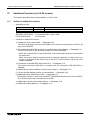
13.Additional Functions (in V.2.00 or later) .............................................13-1
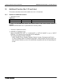
13.1 Outline of additional functions ........................................................................... 13-1
13.2 Connection of bar code reader .......................................................................... 13-2
13.2.1
13.2.2
13.2.3
13.2.4
13.2.5
13.2.6
Connection .............................................................................................................. 13-2
Communication specifications ................................................................................. 13-2
Setting of system information (control devices)....................................................... 13-3
Write to PLC ............................................................................................................ 13-4
Example of sequence program ............................................................................... 13-6
Troubleshooting....................................................................................................... 13-7
13.3 Connection of PLC manufactured by Allen-Bradley .......................................... 13-8
13.3.1 Connection .............................................................................................................. 13-8
13.3.2 Setting of communication ........................................................................................ 13-9
13.3.3 Device list .............................................................................................................. 13-10
13.4 Connection to MELSEC-QnA Series ............................................................... 13-12
13.4.1 CPU direct connection (CPU PORT)..................................................................... 13-12
13.4.2 Computer link connection (LINK PORT)................................................................ 13-12
13.5 Additional key codes........................................................................................ 13-14
13.6 Observe status function ................................................................................... 13-15
13.6.1
13.6.2
13.6.3
13.6.4
13.6.5
13.6.6
13.6.7
Outline of observe status function ......................................................................... 13-15
Observe status cycle ............................................................................................. 13-16
Setting the triggers ................................................................................................ 13-16
Setting the operation ............................................................................................. 13-17
Trigger and number of devices.............................................................................. 13-20
Cautions ................................................................................................................ 13-21
Use example (utilization of clock data) .................................................................. 13-22
13.7 Addition of images for "Touch Key" and "Indicator" objects ............................ 13-23
13.8 Addition of shade patterns ............................................................................... 13-23
14.Additional Function (Ver. 2.10 and Later)...........................................14-1
14.1 Outline of additional function ............................................................................. 14-1
v
15.Additional Functions (V 2.20/3.00 or later) .........................................15-1
15.1 Outline of additional functions ........................................................................... 15-1
15.2 Connection to MELSEC Q Series PLC.............................................................. 15-2
15.2.1 Direct connection to CPU ........................................................................................ 15-2
15.2.2 Connection to serial communication unit................................................................. 15-2
15.3 Connection to PLC manufactured by Siemens.................................................. 15-4
15.3.1 Direct connection to CPU ........................................................................................ 15-4
15.3.2 Support device range list ......................................................................................... 15-5
15.3.3 Device specification method and restraint in GOT .................................................. 15-5
15.4 Connection to machine controller manufactured by YASUKAWA ELECTRIC CORP.
........................................................................................................................... 15-7
15.4.1 Direct connection to CPU ........................................................................................ 15-7
15.4.2 Support device list ................................................................................................... 15-9
15.5 Additional function to connect two or more GOT units when micro computer boards
are used........................................................................................................... 15-10
15.5.1
15.5.2
15.5.3
15.5.4
Setting when two or more GOT units are connected ............................................ 15-10
Communication procedure .................................................................................... 15-12
Communication command..................................................................................... 15-13
Memory map ......................................................................................................... 15-15
vi
Graphic Operation Terminal F930GOT
1.
Introduction 1
Introduction
This section describes the product configuration and the system configuration of the graphic
operation terminal. Confirm diversified functions of each unit.
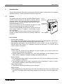
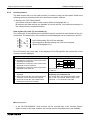
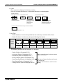
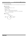
1.1
Outline
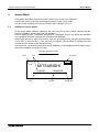
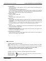
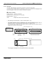
The graphic operation terminal (hereafter abbreviated to
"GOT") is to be mounted on the face of a control panel or
operation panel, and connected to the programming connector of an FX or A Series programmable controller (hereafter abbreviated to "PLC").
Various PLC devices can be monitored and the PLC data
can be changed through the screen of the GOT.
There are several display screens built-in to the GOT which
offer various functions. In addition, user-defined screens
can be created.
The user defined-screens (user screens) and the built-in
screens (system screens) have the following respective
functions.
FX or A
Series PLC
Programming
connector
GOT main body
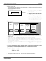
User screens
• Screen display function
User screens can be displayed, and the following functions can be assigned to each screen.
The available screens can be limited using the security function.
Both software packages, FX-PCS-DU/WIN-E (V.2.30 or later) for DU and SW¨D5CGOTRE-PACK (V.H or later) ("¨" indicates a numeric not less than "1".) for GOT, can be
used to create user screens.
Display function
1) Up to 500 user screens can be displayed. In screen creation, two or more screens can
be overlaid or changed over arbitrarily.
2) Simple graphics such as straight lines, circles and rectangles can be displayed, along
with numbers, alphabets, Hiragana, Katakana and Kanji characters.
Monitor function
1) Set values and current values of word devices in the PLC can be displayed in numerics
or bar graphs for monitoring.
2) The specified range of the screen components can be displayed in reverse in accordance with the ON/OFF status of bit devices in the PLC.
Data change function
1) The numeric data being monitored can be changed.
Switch function
1) By manipulating the operation keys in the GOT, bit devices in the PLC can be set to ON
and OFF. The display panel face can be assigned as touch keys to offer the switch function.
1-1
Graphic Operation Terminal F930GOT
Introduction 1
System screens
• Monitor function
Device monitor
1) The ON/OFF status of each device and the set value and the current value of each timer,
counter and data register in the PLC can be monitored and changed.
2) Specified bit devices can be forced ON or OFF.
Unlike the monitor function described in the previous page, the screen data can be
edited by inputting a desired device No. from the keyboard.
• Other functions
Many other functions are built in.
1) A real-time clock is built in, so the current time can be set and displayed.
2) The GOT can function as an interface to enable data communication between the PLC
and a personal computer in which the relay ladder creation software is running. At this
time, the GOT screen can also be displayed.
3) The screen contrast can be adjusted, and the buzzer sound can be turned on or off.
nImportant point
Display screens can be created using the following software.
Screens for DU:
FX-PCS-DU/WIN-E (V.2.20 or later)
Screens for GOT-A900:
SW¨D5C-GOTRE-PACK (V.H or later) ("¨" indicates a numeric not less than "1".)
1-2
Graphic Operation Terminal F930GOT
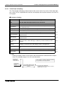
1.2
Introduction 1
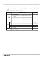
Function list
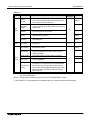
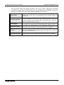
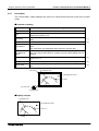
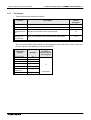
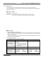
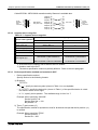
The functions described in the previous page are divided into four modes shown in table below.
The operator can use each function by selecting a corresponding mode.
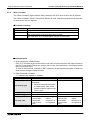
Table 1.1:
Mode
Function
Screen User screen
mode display
Outline of function
Reference
sections
Remarks
Character display
• Characters such as alphabets, numbers, Katakana, Kanji and external characters are displayed.
• Japanese and English are displayed.
3, 8, 9, 11 Note 1
Graphic display
• Graphics such as straight lines, circles and rectangles are displayed.
3, 8, 9, 11
Monitor function
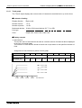
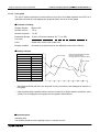
• Set values and current values of word devices (T,
C, D, V and Z) in the PLC can be displayed in the
form of numeric, bar graph, trend graph and
panel meter.
• The color of specified area on the screen is
inverted (between white and blue) in accordance
with the ON/OFF status of bit devices (X, Y, M, S,
T and C) in the PLC.
3, 8, 9, 11
Data change function
• Set values and current values of word devices (T,
C, D, V and Z) in the PLC can be changed in the
form of numeric, bar graph, trend graph and
panel meter.
3, 8, 9, 11
Switch function
• The ON/OFF status of bit devices (X, Y, M, S, T
and C) in the PLC can be controlled in the form
of momentary, alternate and set/reset.
3, 8, 9, 11
Screen changeover
• The display screen can be changed over from
the PLC or a touch key.
3, 10, 12
Recipe function (data file transfer)
• Data saved in the GOT can be transferred to the
PLC.
3, 9, 11
Security function (screen protection function)
• Only screens whose entry code level is equivalent to or lower than the entry code entered by
the operator are displayed. (This function is
available also in the system screens.)
2
Alarm function
• The ON/OFF status of specified bit devices are
monitored, and the number of times of occurrence and the occurrence time of alarms are displayed. Such alarm data can be saved as alarm
history.
7, 11
1-3
Graphic Operation Terminal F930GOT
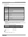
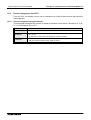
Introduction 1
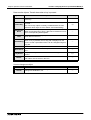
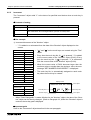
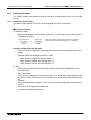
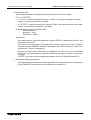
Table 1.1:
Mode
Function
Device
monitor
HPP
mode
Test
mode
•
Reference
sections
The ON/OFF status of bit devices as well as current values and set values of word devices can
be monitored using device Nos.
Remarks
Note 1
Current value •
/ set value
change
Current values and set values of word devices
can be changed using device Nos. and comment
expression.
Forced
ON/OFF
•
Bit devices (X, Y, M, S, T and C) in the PLC can
be forcedly set to ON or OFF.
State
monitor
•
State (S) Nos. in the ON status are automatically
displayed for monitoring.
Valid in FX
Series
PC
diagnosis
•
The error information in the PLC can be read
and displayed.
Valid in FX
Series
•
User screens are displayed in the order of
screen No.
•
A specified bit device can be kept ON for a specified period of time.
•
PC transfer
The screen data and the alarm history can be
transferred between the GOT and the screen
creation software.
Printer output •
The alarm history can be output to a printer.
Screen list
Time switch
Other
mode
Outline of function
Entry code
Environment
setting
•
The entry code to protect programs in the PLC
can be registered.
•
The initial setting can be specified for the system
language, the connected PLC, the serial transfer,
the opening screen, the menu screen call, the
current time, the backlight extinguishing time, the
buzzer ON/OFF, the LCD contrast, the screen
data clear, etc.
4
5
Note 2
6
Note 1: External characters and comments can be created using the screen creation software
(FX-PCS-DU/WIN-E).
Note 2: The function is valid only when the FX-PCS-DU/WIN-E is used.
* When the PLC is connected via a computer link unit, some functions are restricted.
1-4
Graphic Operation Terminal F930GOT
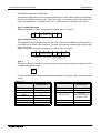
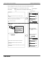
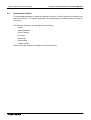
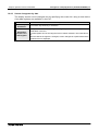
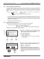
1.3
Format of manual
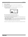
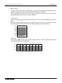
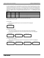
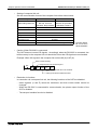
1.3.1
Contents described in manual
Introduction 1
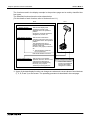
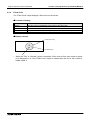
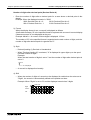
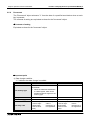
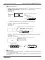
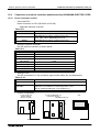
This manual is described in the following format. Use each element of the format for index.
Example:
Startup 2
Graphic Operation Terminal F940GOT
1)
2.
Startup
2.1
Startup procedure
1) Section title
Sections 2 to 6 mainly describe operations.
Sections 7 to 12 descr ibe the contents
required to create screens.
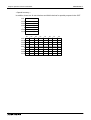
2) Title
The title explains the contents of each paragraph.
2)
2.1.1 GOT setup
3)
3) Sub title
4) Important point
Terms used in the text are explained and supplemented.
4)
nImportant point
MITSUBISHI
1.3.2
2-1
Abbreviations used in text
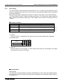
The following terms may be abbreviated in the text.
1) MELSEC FX or A Series unit may be abbreviated to "programmable controller" or "PLC".
2) The software kit to create display screens FX-PCS-DU/WIN-E or SW¨D5C-GOTRE-PACK
may be abbreviated to "software to create screens" or "screen creation software".
3) A general-purpose personal computer may be abbreviated to "PC"
4) A floppy disk may be abbreviated to "FD". A floppy disk drive may be abbreviated to "FDD".
5) The graphic operation terminal F930 Series may be abbreviated to "GOT".
6) Devices inside the PLC may be abbreviated to "X" (input), "Y" (output), "M" (auxiliary relay),
"S" (state), "T" (timer), "C" (counter) and "D" (data register). Output contacts of X, Y, M, S, T
and C may be called "bit devices".
All of them may be called "devices".
1-5
Graphic Operation Terminal F930GOT
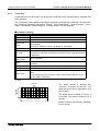
1.4
Introduction 1
Expressions and basic operations of operation keys
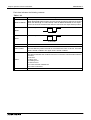
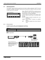
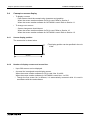
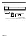
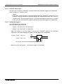
The operation keys are expressed as follows in the text.
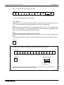
1.4.1
Expressions of operation keys
1) Touch keys on the screen which are actuated when touched by fingers are enclosed with
rectangular frame.
SCREEN MODE , HPP MODE
2) Cursor control keys to be pressed may be expressed as follows.
,
,
3) When a same key is pressed several times or a same operation is repeated, the following
expression may be used.
4) When an arbitrary numeric within the range of 0 to 9 is to be entered, the following expression may be used.
0 to 9
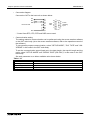
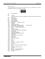
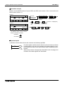
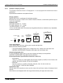
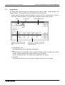
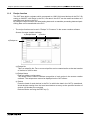
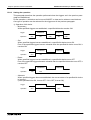
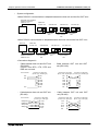
1.4.2
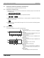
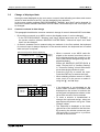
Basic operations
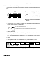
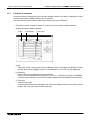
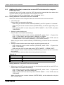
The common operations in the GOT are shown below.
➁
➀
[DEVICE MONITOR]
SET
DEV.
ON
END
OFF
➇
➆
➂
➈
➄
CLR
6
7
8
2
3
4
0
1
9
5
-
ENT
➅
➃
➆
➀ Function display
The selected mode or function is displayed
here.
➁ END key
This key terminates the displayed function, and
returns to the previous screen.
➂ CLR (clear) key
This key cancels the input of alphabets and
numerics.
➃ ENT (enter) key
This key determines the input of alphabets and
numerics.
➄ Ten-key pad
This pad allows to enter numerics.
➅ - (minus) key
➆ ▲ and ▼ (cursor control) keys
➇ SET key
When this key is pressed after an alphabet or
numeric has been entered, the keyboard is displayed.
➈ Input display
This field displays a value input from keys.
1-6
Graphic Operation Terminal F930GOT
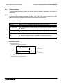
1.5
Introduction 1
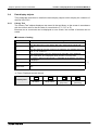
System configuration
This paragraph describes connection of the GOT to a PLC and peripheral unit.
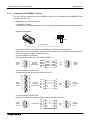
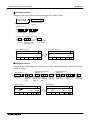
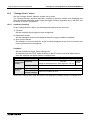
1.5.1
Enlarged view of connectors
A PLC and peripheral unit can be connected to the following connectors in the GOT.
1) Connectors in the GOT
Connectors are provided on the rear face of the GOT.
➀ PLC connector (RS-422 connector) D-sub, 9-pin, female
This connector allows communication with an FX/A Series PLC.
➁ PC connector (RS-232C connector), D-sub, 9-pin, male
This connector links a personal computer having the screen data created using the screen
creation software to allow data transfer.
When the RS-232C connector in the PC is the 9-pin type, use a data transfer cable FX232CAB-1. When the RS-232C connector in the PC is the half-pitch, 14-pin type, use a data
transfer cable FX-232CAB-2.
This connector is used also when the FX2N-232-BD is used for an FX2N Series PLC or when
1:N connection is adopted with "CPU PORT" in an FX/A Series PLC.
* When a PLC is connected via a computer link unit, use either of the connectors ➀ or ➁ above.
1-7
Graphic Operation Terminal F930GOT
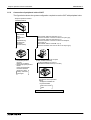
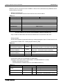
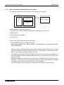
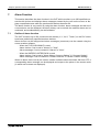
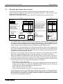
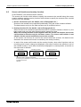
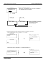
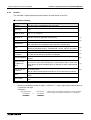
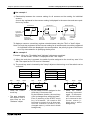
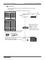
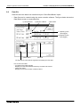
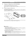
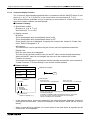
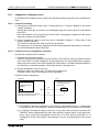
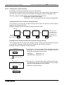
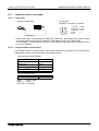
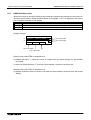
1.5.2
Introduction 1
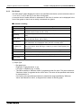
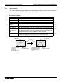
Connection of peripheral units of GOT
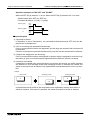
The figure below shows the system configuration required to use the GOT with peripheral units.
ž Graphic operation terminal
F930GOT-BWD-E
Data transfer
cable
F2-232CAB-1
(3 m)
Disabled during
computer link
(RS-232C
communication)
ž Printer
< Dedicated printers >
GT-10A
K6PR(-K), A7(N)PR
< General-purpose printers >
ESC/P
Printer equipped with
RS-232C interface
Data transfer cable FX-232CAB-1 (3 m)
(when the RS-232C connector in the PC is 9-pin type),
Data transfer cable FX-232CAB-2 (3 m)
(when the RS-232C connector in the PC is half-pitch,
14-pin type) or
Data transfer cable F2-232CAB-1 (3 m)
(when the RS-232C connector in the PC is 25-pin type)
ž General-purpose personal computer
(screen creation software)
FX-PCS-DU/WIN-E (V.2.20) or
SW¨D5C-GOTRE-PACK (V.H or later)
Prints out alarm
history and alarm
messages.
ž Printer
PC-PR201H or its equivalent
ESC/P
* A7(N)PR is available for
the A7PHP/HGP.
Prints out screen
data.
Peripheral units of GOT
1-8
Graphic Operation Terminal F930GOT
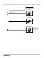
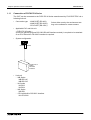
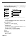
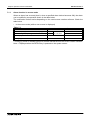
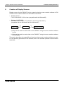
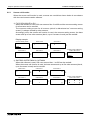
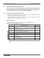
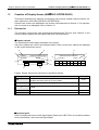
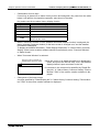
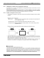
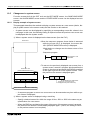
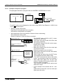
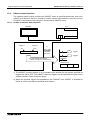
1.5.3
Introduction 1
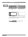
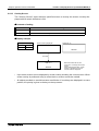
Connection of peripheral units of PLC
When a general-purpose personal computer is directly connected to the GOT, the two-port
interface FX-2PIF (two-port interface function) is not required.
When one GOT and one peripheral unit for sequence program creation are used for one PLC,
the two-port interface FX-2PIF is required. The system configuration required in this case is
shown below.
When the two-port interface FX-2PIF is used
ž Graphic operation terminal
F930GOT-BWD-E
When the two-port interface function is used, the operation environment should
be set for it.
(Refer to the description on "SERIAL PORT" on the SET-UP MODE screen.)
Data transfer cable FX-232CAB-1 (3 m) (when the RS-232C connector in
the PC is 9-pin type),
1
ž Two-port
interface
FX-2PIF
Data transfer cable FX-232CAB-2 (3 m)
(when the RS-232C connector in the PC is half-pitch, 14-pin type) or
Data transfer cable F2-232CAB-1 (3 m)
(when the RS-232C connector in the PC is 25-pin type)
Connection cable FX-40DU-CAB (3 m) or Connection cable FX-40DU-CAB-10M (10 m)
Program cable FX-20P-CAB (1.5 m)
2
Data transfer cable AC30R4 (3 m)
3
Data transfer cable FX-422CAB (0.3 m) or
Data transfer cable FX-422CAB-150 (1.5 m)
Data transfer
cable
FX-422CAB0
ž FX0/FX0S/FX0N/FX2N/
FX2NC Series
ž FX/FX2C/ Series
ž A Series (except QnA)
(Refer to Paragraph 1.8.)
Motion controller
Programmable controller
1-9
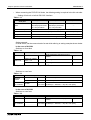
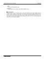
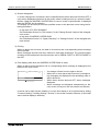
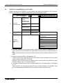
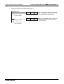
Graphic Operation Terminal F930GOT
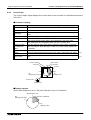
Introduction 1
Peripheral unit to create
sequence programs
* A general-purpose personal computer can be directly
connected, and both the GOT and the personal
computer can be used at the same time (without
using the FX-2PIF).
ž General-purpose
personal computer
1
ž Handy programming
panel FX-10P/20P
2
(A Series cannot be used.)
ž A7PHP/A7HGP
A6GPP/A6PHP
3
The FX2N/FX2NC
Series can be used
in the instruction/
device range of the
FX2 Series.
1-10
Graphic Operation Terminal F930GOT
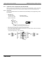
1.6
Introduction 1
Connection of PC
Use the following cable to connect a personal computer.
➀ F930GOT
➁ Personal computer
➂ FX-232CAB-1,
FX-232CAB-2 or
F2-232CAB-1
Pin layout and connection diagram of transfer cables
- Transfer cable FX-232CAB-1
D-sub
(female),
9-pin
1
2
3
4
5
6
7
8
9
PC side
➁
➂
➅
➇
➄
➃
➁
➂
➅
GOT side
➇
➄
➃
1
2
3
4
5
6
D-sub
7
(female),
8 9-pin
9
- Transfer cable FX-232CAB-2
7
·
Half-pitch, ·
·
14-pin
·
·
1
14
·
·
·
·
·
8
➀
➁
➃
➈
PC side
11
14
➂
➃
1
2
➁
➅ GOT side 3
➇
4
➄
5
6
D-sub
7
(female),
8 9-pin
9
12
13
- Transfer cable F2-232CAB-1
D-sub
(male),
25-pin
13
12
11
10
9
8
7
6
5
4
3
2
1
25
24
23
22
21
20
19
18
17
16
15
14
➀
➁
➂
PC side ➄
➅
➆
20
1
➁
2
➂
➇ GOT side 3
4
➃
5
➄
➅
6
D-sub
7
(female),
8 9-pin
9
1-11
Graphic Operation Terminal F930GOT
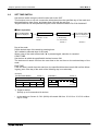
1.7
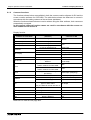
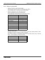
Introduction 1
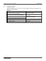
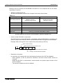
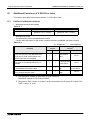
Connection of PLC
Set the connected PLC in "PLC TYPE" of "SET-UP MODE" described in Paragraph 2.2 or in
the screen creation software.
Table 1.2:
Connectable PLC
Connection type
MELSEC FX/FX2C/FX0/FX0S/FX0N/FX2N/FX2NC
Series manufactured by MITSUBISHI
CPU direct (CPU PORT)
MELSEC A Series manufactured by MITSUBISHI
CPU direct (CPU PORT) or computer link
(LINK PORT)
SYSMAC C Series manufactured by OMRON
FLEX-PC N Series manufactured by FUJI ELECTRIC
Computer link (LINK PORT)
PLC manufactured by Allen-Bradely Co., Inc.
Described in Paragraph 13.3
PLC manufactured by Siemens AG
To be available soon
Micro computer board
RS-232C port
1-12
Graphic Operation Terminal F930GOT
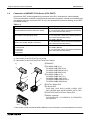
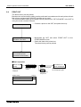
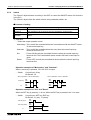
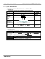
1.8
Introduction 1
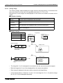
Connection of MELSEC FX/A Series (CPU PORT)
Connect the GOT to the programming connector in the PLC, and perform communication.
This communication method is easy because sequence programs, setting and interface are
not required once the connected PLC is set in the operation environment setting (on the SETUP MODE screen).
Table 1.3:
Series name
FX0/FX0S/FX0N/FX2N/FX2NC/FX/FX2C Series
CPU PORT (RS422)
(In 1:N connection, select "CPU PORT (RS232C)"
for the second and fourth GOTs.)
FX2N (when FX2N-232-BD is used)
CPU PORT (RS232C)
(In 1:N connection, select "CPU PORT (RS422)"
for the second and fourth GOTs.)
CPU PORT (RS422)
AnN, AnA, AnS, AnSJ, AnSH, A1SJH, A2C, A2CJ,
(In 1:N connection, select "CPU PORT (RS232C)"
A0J2H, AnU, AnUS, A2USH, A1FXCPU
for the second and fourth GOTs.)
Motion controller
A171SCPU-S3
A171SHCPU
A172SHCPU
A272UHCPU
CPU PORT (RS422)
(In 1:N connection, select "CPU PORT (RS232C)"
for the second and fourth GOTs.)
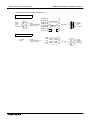
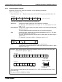
Use the following cables in connection of the PLC.
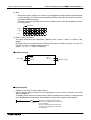
1) Connection of the FX1/FX2/FX2C/A Series
2) Connection of the FX0/FX0S/FX0N/FX2N/FX2NC Series
1)
➀ F930GOT
➁ FX-40DU-CAB (3 m),
2)
FX-40DU-CAB-10M (10 m),
FX-40DU-CAB-20M (20 m) or
FX-40DU-CAB-30M (30 m)
➂ FX-50DU-CAB0 (3 m),
X7
X6
X5
X4
X3
X2
X1
M
CO
N
L
IN
X0
PO
0
1
OU
R
WE
N
RU
2
T
3
0
5
4
1
2
6
3
7
4
5
Y5
Y4
Y3
G¥E
PRO ¥E
CPU
M0
CO
OUT
24+
M
CO
Y0
M1
CO
Y1
M2
CO
Y2
FX-50DU-CAB0-1M (1 m),
FX-50DU-CAB0-10M (10 m),
FX-50DU-CAB0-20M (20 m) or
FX-50DU-CAB0-30M (30 m)
➃ FX/FX2C Series PLC
➄ A Series PLC
AnN, AnA, AnS, AnSJ, AnSH, A1SJH, A2C,
A2CJ, A0J2H, AnU, AnUS, A2USH, A1FX, CPU
➅ FX0/FX0S/FX0N/FX2N/FX2NC Series PLC
➆ Motion controller
A171SCPU-S3, A171SHCPU, A172SHCPU,
A272UHCPU
* If the screen mode is selected while cables are not connected, a communication error occurs.
1-13
Graphic Operation Terminal F930GOT
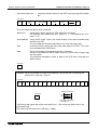
Introduction 1
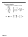
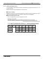
Pin layout and connection diagram of connection cables
(Connection cables are offered as options.)
- Connection cables FX-40DU-CAB(-10M/-20M/-30M) and FX-50DU-CABL
D-sub
(male),
25-pin
13
12
11
10
9
8
7
6
5
4
3
2
1
25
24
23
22
21
20
19
18
17
16
15
14
➁
➂
➃
➄
➆
PLC side
➀
➁
➂
➃
➄
➅
➆
➇
➈
15
16
17
18
5
4
3
2
1
GOT
side
9
D-sub
8
(male),
7 9-pin
6
➇
21
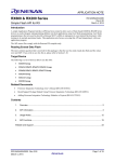
- Connection cable FX-50DU-CAB0(-1M/-10M/-20M/-30M)
3
4
6
MINI-DIN
1
(male),
2
8-pin
7
5
8
PLC side
➁
➆
➅
➂
➀
➃
➄
➀
➁
➃
➄
➅
➆
➈
GOT
side
5
4
3
2
1
9
D-sub
8
(male),
7 9-pin
6
1-14
Graphic Operation Terminal F930GOT
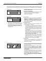
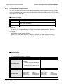
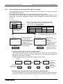
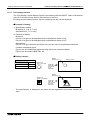
Introduction 1
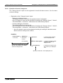
• In the case of CPU direct connection with the FX/A Series PLC, up to four GOTs can be
connected to one PLC (1:N connection).
Select "CPU PORT (RS-232C)" or "CPU PORT (RS-422)" as the connection type.
System configuration
FX/A Series GOT rear face
1st GOT
Communication via
RS-422
Maximum extension
distance: 30 m
2nd GOT
Communication
via RS-232C
15 m
3rd GOT
4th GOT
Communication
Communication
via RS-422
via RS-232C
30 m
15 m
Note:
A peripheral unit of the GOT or a peripheral unit to create sequence programs cannot be
used at the same time with the GOT except in the system configuration shown below using
the FX2N-422-BD in the FX2N Series. Only either a peripheral unit or the GOT can be connected at a time.
Connection cable examples:
1st GOT: FX-50DU-CAB0 (equivalent to connection cable for the PLC)
2nd GOT: FX-232CAB-1 (3 m)
3rd GOT: Cable created by user (Refer to the connection diagram.)
4th GOT: FX-232CAB-1 (3 m)
Communication speed:
The communication speed (= baud rate) with the PLC becomes slower as the number of
GOTs increases.
When the communication speed in the first GOT is supposed as "1",
2nd GOT: Communication speed in the 1st GOT × 2 (= 1/2 of that in the 1st GOT)
3rd GOT: Communication speed in the 2nd GOT × 2 (= 1/4 of that in the 1st GOT)
4th GOT: Communication speed in the 3rd GOT × 2 (= 1/8 of that in the 1st GOT)
Connection diagram
➀
➁
➂
➃
➄
➅
➆
➇
➈
➀
➁
➂
➃
➄
➅
➆
➇
➈
• In the FX2N Series, the connection shown above can be realized by using the FX2N-422-BD.
In this case, a peripheral unit to create sequence programs can be connected to the programming connector in the FX2N.
1-15
Graphic Operation Terminal F930GOT
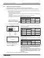
Introduction 1
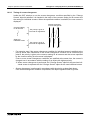
• In the case of connection with the FX2N Series PLC, communication can be performed
through CPU direct connection (RS-232C) by using the FX2N-232-BD.
In this case also, up to four GOTs can be connected to one PLC (1:N connection).
In connection of a peripheral unit to create sequence programs, use the programming connection in the FX2N main unit.
System configuration
Communication via
RS-232C
Maximum extension
distance: 15 m
GOT rear face
1st GOT
FX2N-232-BD is used.
2nd GOT
3rd GOT
4th GOT
Communication
Communication
Communication
via RS-422
via RS-422
via RS-232C
30 m
30 m
15 m
Connection cable examples:
1st GOT: FX-232CAB-1
2nd GOT: Cable created by user (Refer to the connection diagram.)
3rd GOT: FX-232CAB-1
4th GOT: Cable created by user (Refer to the connection diagram.)
Communication speed:
The communication speed (= baud rate) with the PLC becomes slower as the number of
GOTs increases.
When the communication speed in the first GOT is supposed as "1",
2nd GOT: Communication speed in the 1st GOT × 2 (= 1/2 of that in the 1st GOT)
3rd GOT: Communication speed in the 2nd GOT × 2 (= 1/4 of that in the 1st GOT)
4th GOT: Communication speed in the 3rd GOT × 2 (= 1/8 of that in the 1st GOT)
Connection diagram
➀
➁
➂
➃
➄
➅
➆
➇
➈
➀
➁
➂
➃
➄
➅
➆
➇
➈
1-16
Graphic Operation Terminal F930GOT
Introduction 1
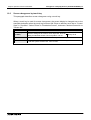
<Cautions on connection of two or more GOT units>
When two or more GOT units are connected to the FX/A/QnA Series PLC, communication is
performed in the location sequence from the GOT unit nearest to the CPU (that is, in the
sequence of the 1st, 2nd, 3rd and 4th GOT units). Accordingly, when turning on the power of
the GOT units for the first time, turn on the power from the one nearest to the CPU.
If the power cannot be turned on in the GOT units from the one nearest to the CPU, set the
GOT units (in "SET-UP MODE") or the screen creation software so that communication is performed while the title screen display time is different by 2 to 3 seconds in each GOT unit.
Setting example:The title screen display time is different by 2 seconds in each GOT unit, and
communication is started from the GOT unit nearest to the CPU.
FX/A/QnA
Title screen display time (initial value: 4 sec)
1st GOT: 4 sec
2nd COT: 6 sec
3rd COT: 8 sec
4th COT: 10 sec
* Perform the same setting without regard to the connection type (RS-232C or RS-422) of two
or more GOT units.
1-17
Graphic Operation Terminal F930GOT
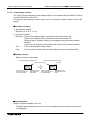
1.9
Introduction 1
Connection of MELSEC A Series (LINK PORT)
The GOT can be connected to the MELSEC A Series via a computer link unit shown below.
• Applicable PLC and computer link unit
< A Series >
AJ71UC24, A1SJ71UC24-R2/R4/PRF, A1SJ71C24-R2/R4/PRF, A1SCPUC24-R2,
A2CCPUC24 (PRF)
System configuration
RS422
Programming
connector is not
used.
RS232C
Refer to the figure on the right
for connection diagram.
To computer link unit
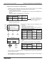
• Connect the GOT to the computer link unit (PLC) as shown below.
In communication via RS-422
Terminal
block
Computer link
unit side
(PLC side)
5
➀
4
➅
GOT
➁ side 3
2
➆
1
➄
RDA
RDB
SDA
SDB
SG
9
8
7
6
D-sub
(male),
9-pin
In communication via RS-232C
(Connection cable F2-232CAB is also available.)
13
12
11
10
9
8
D-sub,
25-pin 7
6
5
4
3
2
1
25
24
23
22
21 Computer link
20
unit side
19
(PLC side)
18
17
16
15
14
FG ➀
SD ➁
RD ➂
RS ➃
CS ➄
DSR ➅
SG ➆
CD ➇
DTR 20
➀
➁
➂
➆
➇
➅
➄
1
2
GOT
side 3
4
5
6
D-sub
7
(female),
8 9-pin
9
➃
1-18
Graphic Operation Terminal F930GOT
Introduction 1
In communication via RS-232C
5
4
D-sub, 3
9-pin
2
1
9
8
7
6
CD ➀
RD ➁
SD ➂
Computer link
DTR ➃
unit side
(PLC side) SG ➄
DSR ➅
RS ➆
CS ➇
➀
➁
➂
➃
➄
➅
➆
➇
1
2
GOT
side 3
4
5
6
D-sub
7
(female),
8 9-pin
9
1-19
Graphic Operation Terminal F930GOT
Introduction 1
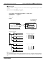
When the GOT is connected to the MELSEC A Series PLC via a computer link unit, the following setting is required.
• Setting of computer link unit
Set the communication format of the computer link unit as shown below.
Table 1.4:
Used port
When RS-422 is used
When RS-232C is used
Mode setting switch No.
5
RS-422: Format 1
RS-232C: No-procedure
1
RS-422: No-procedure
RS-232C: Format 1
Transmission speed
19200 bps
Data bit
7 bits
Stop bit
1 bit
Parity bit
Even
Sum check
Provided
Write during run
Possible
Station No.
00 to 0F (in accordance with setting in GOT)
↑
The GOT station No. can be set in "SET-UP MODE". (Refer to Paragraph 2.2.)
• Caution: When RS-232C is connected
The GOT does not control CD signals. Accordingly, when the RS-232C is connected, the
buffer memory in the computer link unit should be set so that CD signals are not checked.
Example: When I/O signals in the computer link unit are 80 (H) to 9F (H)
Write to buffer memory
Computer link unit connection point
X87
TO P
H8
H10B
K1
K1
K1: CD terminal will not be checked.
10B (H): CD terminal will be checked.
• Restriction in functions
In connection via computer link unit, the following functions of the GOT are disabled.
- Index registers (V and Z) cannot be monitored, and their current values cannot be
changed.
- When the RS-232C is connected for communication, the printer output function of the
GOT is disabled.
- The two-port interface function is disabled.
1-20
Graphic Operation Terminal F930GOT
1.10
Introduction 1
Connection of SYSMAC C Series
The GOT can be connected to the SYSMAC C Series PLC manufactured by OMRON via the
following host link unit.
• Applicable PLC and host link unit
< SYSMAC C Series >
Host link unit is required be attached. Or a CPU with built-in interface for host link is required.
System configuration
RS422
RS232C
To host link unit
• Connect the GOT to the host link unit (SYSMAC C Series) as shown below.
When the GOT is connected to any model not shown in the connection examples below,
refer to the manual of each C Series link unit.
In communication via RS-422
Example of connection with the C200H-LK202-V1
D-sub
(male),
9-pin
5
4
3
2
1
RDB ➀
9
RDA ➅
Host link
8
unit side
SDB ➄
7 (C200H side) SDA
➈
6
SG ➂
➀
➅
➁
➆
➄
GOT
side
5
4
3
2
1
9
8
7
6
D-sub
(male),
9-pin
In communication via RS-232C
Example of connection with the C200H-LK201-V1
13
12
11
10
9
8
D-sub
7
(male), 6
25-pin 5
4
3
2
1
25
24
23
22
21
Host link
20
unit side
19
18 (C200H side)
17
16
15
14
FG
SD
RD
RS
CS
SG
➀
➁
➂
➃
➄
➆
➀
➁
➂
➆
➇
➄
GOT
side
5
4
3
2
1
6
7
8
9
D-sub
(female),
9-pin
6
7
8
9
D-sub
(female),
9-pin
In communication via RS-232C
Example of connection with the CQM1 (with built-in RS-232C port)
D-sub
(male),
25-pin
5
4
3
2
1
9
8
7
6
FG
SD
RD
(COM1 side)
RS
CS
SG
➀
➁
➂
➃
➄
➈
➀
➁
➂
➆
➇
➄
GOT
side
5
4
3
2
1
1-21
Graphic Operation Terminal F930GOT
Introduction 1
When the GOT is connected to the SYSMAC C Series PLC manufactured by OMRON, the following setting is required.
• Setting of host link unit
Set the communication format of the host link unit as shown below.
Table 1.5:
Used port
When RS-422 is used
Transmission speed
When RS-232C is used
19200 bps
Data bit
7 bits
Stop bit
2 bit
Parity bit
Even
Communication mode
Host link mode
Command level
Level 1, 2 or 3
Procedure
1:N procedure
Unit No.
00 to 15 (BCD) (in accordance with setting in GOT)
↑
The GOT station No. can be set in "SET-UP MODE". (Refer to Paragraph 2.2.)
Only a model in which these set items are offered can be connected to the GOT.
Setting example:
Set the communication format while referring to setting examples of each C Series host link unit.
In the case of CQM1-CPU : Setting by data memory (DM)
Table 1.6:
Set item
Set item
Remarks
Standard communication condition (RS-232C: DN6645)
0001H
Mode specification: Host link
Communication condition: In accordance with DM6646
Communication condition
(RS-232C: DM6646)
0304H
Transmission format: 7 data bits and 2 stop bits
Parity: Even Transmission speed: 19,200 bps
Send delay time
(RS-232C: DM6647)
Unit No. (RS-232C: DM6648)
0000H
0 second
(initial status)
00××H
××: Two-digit BCD (in accordance with setting in GOT)
In the case of host link unit attached to C200H base :
Setting by each switch (when C200H-LK201-V1/C200H-LK202-V1 is used)
- Setting of switches on front face
(common between C200H-LK201-V1 and C200H-LK202-V1)
Table 1.7:
Set item
Switch setting
Remarks
SW1
*1
Upper digit BCD
SW2
*1
Lower digit BCD
Transmission speed
SW3
6
19200 bps
Communication condition
SW4
2
7 ASCII bits and 2 stop bits
Parity: Even Command level: 1, 2 or 3
Unit No.
*1 Equivalent to station No. setting in the GOT
1-22
Graphic Operation Terminal F930GOT
Introduction 1
- Setting of switches on rear face (C200H-LK201-V1)
Table 1.8:
Set item
Switch setting
Remarks
Procedure
DTP.SW No.3
ON
1:N procedure
5 V power supply
DTP.SW No.4
OFF
5 V is not supplied.
CTS changeover
Selector switch Upper side External
(C200H-LK202-V1)
Table 1.9:
Set item
Switch setting
Procedure
Right selector switch
Connection of terminal resistor
Left selector switch
Remarks
Lower side 1:N procedure
Upper side Provided
• Cautions
Operation mode of the SYSMAC C Series
When changing the current value and the set value of each device in the C Series PLC, the
PLC should be set to the monitor mode.
If the GOT is connected and the C Series PLC is started up in the running mode, the GOT
automatically sets the PLC to the monitor mode so that the data can be changed.
Table 1.10:
Mode of PLC at startup
GOT operation
Running mode
GOT changes over PLC from running mode to monitor mode to enable
data change.
Monitor mode
PLC remains in monitor mode, and data change is enabled.
Program mode
PLC remains in program mode, and data change is enabled.
- Forced setting to ON/OFF in the HPP mode (GOT function)
In the HPP mode of the GOT, the forced ON/OFF function is available. This function is
available also when the C Series PLC is connected as the host unit.
However, have in mind that the forced ON/OFF function offers the following operation in
the C Series PLC.
* The forced setting/resetting function in the C Series PLC holds the current ON/OFF status without regard to a sequence program.
The forced ON/OFF function described here sets a specified bit to ON/OFF. If a
sequence program gives an ON/OFF command after that, the status of the specified bit
device which has been forcedly set to ON/OFF is changed.
Forced ON : Data "1" is specified. (The specified bit is set to ON.)
Forced OFF : Data "0" is specified. (The specified bit is set to OFF.)
• Restriction in functions
When a host link unit is connected, the following GOT functions are disabled or restricted.
- Because the GOT switch function (which sets a bit to ON/OFF) uses a host link command, FK command (which sets/resets multi-points forcedly), the switch function is not
available in models which do not support the FK command.
- The set value of timers (T) and counters (C) cannot be monitored nor changed.
- When the RS-232C is connected for communication, the printer output function of the
GOT is disabled.
1-23
Graphic Operation Terminal F930GOT
1.11
Introduction 1
Connection of FLEX-PC N Series
The GOT can be connected to the FLEX-PC N Series manufactured by FUJI ELECTRIC via a
following link unit.
• Connection type
:LINK PORT (RS-422)
:LINK PORT (RS-232C)
:CPU PORT (RS-232C)
Select either one by the environment setting or the software to create screens.
• Applicable PLC and link unit
< FLEX-PC N Series >
A link unit (general-purpose RS-232C/RS-485 interface module) is required to be attached.
Or a CPU with built-in RS-232C interface is required.
• System configuration
RS422
RS232C
To link unit or
built-in
RS-232C
interface
• Link unit
- NB Series
NB-RS1-AC
NB-RS1-DC
- NJ Series
NJ-RS2
NJ-RS4
- NS Series
NS-RS1
- CPU with built-in RS-232C interface
NJ-CPU-B16
1-24
Graphic Operation Terminal F930GOT
Introduction 1
• Connection diagram
Connect the GOT to the link unit (PLC) as shown below.
In link connection (RS-422)
Terminal
block
Link unit side
(PLC side)
➀
➅
➁
➆
➄
RDA
RDB
SDA
SDB
SG
5
4
GOT
3
side
2
1
9
8
7
6
D-sub
(male),
9-pin
In link connection (RS-232C)
13
12
11
10
9
D-sub
8
(male), 7
6
25-pin
5
4
3
2
1
25
24
23
22
21
20 Link unit side
19 (PLC side)
18
17
16
15
14
FG ➀
SD ➁
RD ➂
RS ➃
CS ➄
DSR ➅
SG ➆
DTR 20
➀
➁
➂
➆
➇
➅
➄
➃
GOT
side
5
4
3
2
1
6
7
8
9
D-sub
(female),
9-pin
GOT
side
5
4
3
2
1
6
7
8
9
D-sub
(female),
9-pin
In connection of built-in RS-232C interface
D-sub
(male),
15-pin
8
7
6
5
4
3
2
1
15
14
13
12
11
10
9
PLC side
RD
SD
RS
CS
SG
➁
➂
➃
➄
➆
➁
➂
➆
➇
➄
1-25
Graphic Operation Terminal F930GOT
Introduction 1
• When connecting the FLEX-PC N Series, the following setting is required in the link unit side.
- Setting of link unit or built-in RS-232C interface
Table 1.11:
Connection type of
used port
Mode
RS-422 (LINK PORT)
RS-232C (LINK PORT)
RS-232C (CPU PORT)
3: Set by command
Start-stop synchronization, non-procedure
1: Set by command
Start-stop synchronization, non-procedure
Transmission speed
19,200 (bps)
Data bit
7 bits (JIS)
8 bits (HEX)
Parity bit
Even
Odd
00 to 15 (in accordance with setting in GOT)
Station No.
Setting example:
In the N Series, set the communication format while referring to setting examples shown below.
In the case of NJ-RS4
Switches on front face
Table 1.12:
Set item
Description
Remarks
Mode
MODE SW
3
Set by command, start-stop synchronization
Station No.
Station No. setting
switch × 10
*1
Upper digit
×1
*1
Lower digit
No-procedure
*1 Align it with the station No. setting in the GOT.
Switches on rear face
Table 1.13:
Set item
Terminal
resistor
Description
Remarks
Selector switch 1
ON
Receive line is provided.
Selector switch 2
ON
Send line is provided.
CommunicaDIP.SW
tion condition
1:OFF Set by switch
2 to 8:ON 19,200 bps, 7 data bits, 1 stop bit, even parity
In the case of NJ-RS2
Switches on rear face
Table 1.14:
Set item
Mode
Description
MODE SW
CommunicaDIP.SW
tion condition
Remarks
1
Set by command, start-stop synchronization
No-procedure
1:OFF Set by switch
2 to 8:ON 19,200 bps, 7 data bits, 1 stop bit, even parity
1-26
Graphic Operation Terminal F930GOT
NJ-CPU-B16
Introduction 1
Setting by parameter (50H)
Parameter (50H): 0057H
Communication speed
Stop bit
Character length
Parity
: 19,200 bps
: 1 bit
: 8 bits
: Odd
• When connecting the FLEX-PC, have in mind the following restrictions.
- The set values of timers (T) and counters (C) cannot be monitored nor changed.
- When the RS-232C is connected for communication, the printer output function of the
GOT is disabled.
1-27
Graphic Operation Terminal F930GOT
1.12
Introduction 1
Connection by general-purpose communication
The GOT can be connected to a general controller such as a micro computer board.
(The connected controller is hereafter referred to as "host (unit)".)
• Outline
In general-purpose communication, the host unit is connected to the GOT via the RS-422/
RS-232C, and functions as the parent station. Inside the GOT, there is a data area to hold
word data and bit data. The host unit can read from and write to the data area using communication commands.
The contents of display and control in the GOT are determined by the screen data created
using the screen creation software in the personal computer. The screen data specifies the
layout of objects displayed on the screen, and specifies actions to be performed by pressing
of touch keys.
The GOT is equipped with the function to display the word data in the form of numerics and
bar graphs, the function to access the data for changing the status of the bit data using
switches, etc. The target of access at this time is the data area inside the GOT. The data
location to be accessed is specified by the screen data.
Accordingly, to display the data stored in the host unit on the screen, the host unit should
transfer the data to the data area inside the GOT using write commands. The transfer destination is a location specified by the screen data. The data change result by manipulation of
keys can be transferred from the data area inside the GOT to the host unit if the host unit
gives read commands. In general-purpose communication, interrupt codes can be sent as
change triggers.
GOT
Host unit
(micro computer board)
Screen data
Display/Input
Internal data
RS-422 or
RS-232C
1-28
Graphic Operation Terminal F930GOT
Introduction 1
• Connection diagram
Connect the GOT to the host unit as shown below.
➀
➁
➂
➆
➇
➅
➃
➄
FG
SD
RD
Host unit side
SG
5
4
GOT
side 3
2
1
9
D-sub
8
(female),
7 9-pin
6
* Control lines RTS, CTS, DTR and DSR are not used.
• Communication setting
The setting related to communication can be performed using the screen creation software
or the GOT main body. (As to the screen creation software, refer to the operation manual of
the software.)
To use general-purpose communication, select "SET-UP MODE", "PLC TYPE" and "UNIVERSAL" in this order in the GOT main body.
To set the communication speed (baud rate), the data length, the stop bit length and the
parity, select "SET-UP MODE" and "SERIAL PORT (RS-232C)" in this order in the GOT
main body.
Set each parameter to an either available value shown below.
Table 1.15:
Baud rate
19,200, 9,600, 4,800, 2,400, 1,200, 600 or 300 (bps)
Data length
8 or 7bits
Stop bit length
1 or 2bits
Parity
Even, odd or none
1-29
Graphic Operation Terminal F930GOT
Introduction 1
• Communication procedure
In communication between the GOT and the host unit, the host unit sends a command, and
the GOT sends back a response. While the GOT is sending the response to the host unit,
the GOT cannot receive new commands from the host unit.
Host unit
Command
Command
Response
GOT
Command
Response
Response
When an error occurs, the GOT sends back a NAK code as a response. The contents of the
error can be checked by reading a special memory.
As an exception, when a notification of interrupt from the GOT is given, the GOT sends an
interrupt code. However, while sending a response, the GOT does not send an interrupt
code. In such a case, immediately after sending a response, the GOT sends an interrupt
code. The GOT may send an interrupt code while receiving a command.
Host unit
GOT
Interrupt
When an event such as change in the ON/OFF status of a specific bit and screen
changeover has occurred, the GOT sends an interrupt code. The table below shows the
correspondence between the interrupt code and the event type.
Table 1.16:
Event type
Interrupt code (hexadecimal)
M8000 is changed to ON.
M8000 is changed to OFF.
50
51
M8001 is changed to ON.
M8001 is changed to OFF.
52
53
žžž
M8023 is changed to ON.
M8023 is changed to OFF.
7E
7F
žžž
M8049 is changed to ON.
M8049 is changed to OFF.
B2
B3
Display screen is changed over.
20
Input of a numeric is completed.
21
Transfer of a data file is completed.
22
1-30
Graphic Operation Terminal F930GOT
Introduction 1
• Transmission statement configuration
Transmission statements sent and received between the GOT and the host unit are classified into the following three formats. Type 1 and Type 2 can replace each other. When the
sum is not attached to a command, use Type 1. When the sum is attached, use Type 2.
Type 1 (without the sum)
When a command is Type 1, a response to it will be Type 1 or Type 3.
STX
Transmission data
CR
Type 2 (with the sum)
The targets of the sum are the entire text and ETX. The result of addition (excluding STX) is
converted into an ASCII code and sent. The sum consists of the upper digit and the lower
digit in this order.
When a command is Type 2, a response to it will be Type 2 or Type 3.
STX
Transmission data
ETX
Sum
Type 3
This type of format consists of only one character. This format is used for responses (ACK
or NAK) and interrupt codes.
Data
The table below shows characters available in statements. Interrupt codes includes unused
codes.
Table 1.17:
Character code
(hexadecimal)
Character code
(hexadecimal)
STX
02
Interrupt code
20 to 2F
ETX
03
Interrupt code
50 to 7F
CR
0D
ACK
06
Interrupt code
NAK
15
80F to FF
Valid only when data
length is 8 bits
‘0’ to ‘9’
30 to 39
‘A’ to ‘F’
41 to 46
1-31
Graphic Operation Terminal F930GOT
Introduction 1
• Command
Use the following commands for communication with the GOT.
- Read : Read the data stored in the GOT.
Command
STX
'0'
Read address
Size
CR
Type 2 may be used.
"0" at the head indicates a read command.
Read address:
Using ASCII codes, specify the head address (hexadecimal) of the data stored in the
GOT. The read address should be specified in turn from the upper digit.
Size:
In the unit of byte, specify the size of the read data (01H to FFH). The maximum allowable size is 255 bytes. "FFH" indicates 255 bytes. The size should be specified in the
order of upper digit and lower digit (in ASCII codes). For example, enter "8 + A" to specify
8AH bytes (= 138 bytes).
Response
STX
žžžžžžžžžžžžžžžžžžžžžžžžžžžžžžžžž
Data 2
Data 1
CR
Data:
The data stored in the specified address is stored in turn.
One-byte data is converted into ASCII codes, and sorted in the order of upper digit and
lower digit.
Example: When 2-byte data is read from the address 12EH (format = Type 2)
Command
STX
'0'
'0'
'1'
'2'
'E'
'0'
'2'
ETX
'6'
'D'
02H 30H 30H 31H 32H 45H 30H 32H 03H 36H 44H
Sum = 6DH
Response
STX
'5'
Memory inside GOT
'A'
'3'
'8'
ETX
'E'
'4'
02H 35H 41H 33H 38H 03H 45H 34H
Sum = E4H
12E
12F
5A
38
Each data is expressed
in hexadecimal.
1-32
Graphic Operation Terminal F930GOT
Introduction 1
- Write : Overwrite the data stored in the GOT.
Command
STX
'1'
Write address
Size
Data 1
Data 2
CR
Type 2 may be used.
"1" at the head indicates a write command.
Write address:
Using ASCII codes, specify the head address (hexadecimal) of the data stored in the
GOT. The write address should be specified in turn from the upper digit.
Size:
In the unit of byte, specify the size of the write data (01H to FFH). The maximum allowable size is 255 bytes. "FFH" indicates 255 bytes. The size should be specified in the
order of upper digit and lower digit (in ASCII codes).
Data:
Sort the write data in the ascending order of address.
Convert one-byte data into ASCII codes, and sort it in the order of upper digit and lower
digit.
The maximum allowable number of data is 255 (510 after converted into ASCII codes).
Response
ACK
Example: When 2-byte data is written to the address 120H (format = Type 2)
Command
STX
'1'
'0'
'1'
'2'
'0'
'0'
'2'
'3'
'E'
'7'
'5'
ETX
'3'
'D'
02H 31H 30H 31H 32H 30H 30H 32H 33H 45H 37H 35H 03H 33H 44H
Response
ACK
06H
Memory inside GOT
120
121
3E
75
Each data is expressed
in hexadecimal.
120H stores the upper side of the word data D144. 121H stores the lower side of the word
data D144. The value of D144 is 3E75H (= 15989).
1-33
Graphic Operation Terminal F930GOT
Introduction 1
• Memory map
The data stored in the GOT is classified into two types, word data (D) and bit data (M). An
address is assigned to each data, and each data is laid out as follows.
When specifying data using the screen creation software, use the device (D or M). When
specifying data from the host unit, use the address.
< Word data >
There are 4,096 word devices, and a serial No. (from 0 to 4,095) is assigned to each of
them.
Each word data is stored in the order of upper side and lower side. In the case of a double
word (32-bit) data, data is stored from the higher address to the lower address.
0000
D0 (H)
0001
D0 (L)
0002
D1 (H)
0003
D1 (L)
žžž
1FFE
D4095 (H)
1FFF
D4095 (L)
< Bit data >
There are 2,048 bit devices, and a serial number (from 0 to 2,047) is assigned to each of
them. Each address stores 8-bit data.
b6
b5
b4
b3
b2
b1
b0
2000 M 7
b7
M 6
M 5
M 4
M 3
M 2
M 1
M 0
2001 M 15
M 14
M 13
M 12
M 11
M 10
M 9
M 8
žžž
20FF M2047 M2046 M2045 M2044 M2043 M2042 M2041 M2040
1-34
Graphic Operation Terminal F930GOT
Introduction 1
< Special memory >
In addition, there are 16 word devices and 64 bit devices for special purpose in the GOT.
2100
D8000 (H)
2101
D8000 (L)
2102
D8001 (H)
2103
D8001 (L)
žžž
211E
D8015 (H)
211F
D8015 (L)
b7
b6
b5
b4
b3
b2
b1
b0
2200 M8007 M8006 M8005 M8004 M8003 M8002 M8001 M8000
2201 M8015 M8014 M8013 M8012 M8011 M8010 M8009 M8008
2202 M8023 M8022 M8021 M8020 M8019 M8018 M8017 M8016
2203 M8031 M8030 M8029 M8028 M8027 M8026 M8025 M8024
2204 M8039 M8038 M8037 M8036 M8035 M8034 M8033 M8032
2205 M8047 M8046 M8045 M8044 M8043 M8042 M8041 M8040
2206 M8055 M8054 M8053 M8052 M8051 M8050 M8049 M8048
2207 M8063 M8062 M8061 M8060 M8059 M8058 M8057 M8056
1-35
Graphic Operation Terminal F930GOT
Introduction 1
Each data indicates the following contents.
Table 1.18:
Device
M8000 to M8049
Description
Interrupt output
When the bit data status changes, the GOT sends an interrupt code to the host unit.
When the data length is 7 bits, interrupt codes for M8024 to M8049 are not output.
Even if the host unit overwrites this data, the GOT does not output interrupt codes.
1-second cycle clock
M8050
1 second
2-second cycle clock
M8051
2 seconds
M8052 to M8063
Unused
D8000, D8001
32-bit counter of 100 ms
The time after the power is turned on is counted in the units of 100 ms. The lower
word is stored in D8000. The upper word is stored in D8001.
D8002
Contents of communication error
This device indicates the contents of an error occurred in communication with the
host unit.
0: No error
1: Parity error
2: Framing error
3: Overrun error
4: Incorrect format of statement
5: Incorrect command
D8003 to D8015
Unused
1-36
Graphic Operation Terminal F930GOT
Introduction 1
• Program example
This program writes "31,000" to D10, and "15,600" to D11. In hexadecimal, "31,000" is
expressed as "7918H", and "15,600" as "3CF0H".
D10
D11
10'
20'
500
530
610
620
630
640
1000
1010
1020
1030
1040
1100
1110
1120
1130
1140
1150
1160
1170
1180
1190
1700
1710
2000
2010
2020
2100
2110
2120
2130
2140
2150
2160
2200
2210
2220
Sample program
T0=3000
: ‘ Counter waiting for receive (to be adjusted in accordance with speed of computer)
ERFLG=0
STX$=CHR$(2)
CR$=CHR$(13)
ACK$=CHR$(6)
NAK$=CHR$(&H15)
* DATASEND
: ‘ Send of statement
CLOSE#1
OPEN"COM1:"AS#1
SENDDATA$="100140479183CF0"
: ' Send statement
PRINT#1,STX$;SENDDATA$;CR$;
* REC0
: ' Receive of first character
RVCNT=1
GOSUB *JYUSHIN
IF ERFLG=99 THEN GOTO *ERRORFIN1
BUF$=RCV$
HED$=LEFT$(BUF$,1)
IF HED$=ACK$ THEN GOTO *FIN
* ERRORFIN1
PRINT "Error code is sent back."
GOTO *FIN
* ERRORFIN1
PRINT "No response"
* FIN
CLOSE#1
END
* JYUSHIN : ' Waiting for receive
FORI=1 TO T0
RCV$=""
IF LOC(1)=>RVCNT THEN GOTO *BUFIN
NEXT
IF RCV$=""THEN ERFLG=99
RETURN
* BUFIN : ' Read of receive data
RCV$=INPUT$(RVCNT,#1)
RETURN
1-37
Graphic Operation Terminal F930GOT
1.13
Introduction 1
Save destination and backup of screen data
The following data is saved in the RAM or the flush memory of the GOT.
GOT
Screen creation software
RAM ➁ to ➃
RAM
Transferred
Personal computer
➀
Flush memory
➀
RAM area: Backed up by built-in battery.
1) Contents set in "SET-UP MODE" (described in Paragraph 2.2) in the GOT
2) Alarm history
3) Data collected by sampling
4) Current time
Flush memory area: Does not require any battery.
1) Data created by the screen creation software
Screen data and data set in "SET-UP MODE", "ALARM MODE" and "SAMPLING MODE
(SET CONDITION)"
• When the data is transferred between the screen creation software and the GOT, the data
saved in the RAMs 2, 3 and 4 and the flush memory 1 is transferred. The data saved in the
RAM 1 is not transferred to the personal computer.
• The operation environment (SET-UP MODE) can be set in the GOT (saved in the RAM 1) or
the screen creation software (saved in the flush memory 1), and the priority is given to the
contents set later.
When the operation environment is set in the GOT, the contents of the setting are saved in
the RAM 1. In this case, if the battery power becomes low, the saved data may be deleted
or uncertain, and communication with the PLC may be disabled.
It is recommended to set the operation environment in the screen creation software.
1-38
Graphic Operation Terminal F930GOT
2.
Start up 2
Start up
This section describes the start up procedure from turning ON the power of the GOT to selection of the mode.
This section describes also the environment setting important to use of the GOT. Make sure to
read this section carefully.
2.1
Start up procedure
This paragraph describes the start up procedure form turning ON the power of the GOT to
selection of the mode.
Ÿ Perform wiring of the power supply unit of the GOT.
Perform wiring of the
power supply unit of the
GOT.
Ÿ Connect the GOT and the PLC with an optional connection cable.
Connect the PLC.
Turn on the
Turn on the
power without power while
pressing the pressing the
touch key.
touch key.
Ÿ Turn on the power of the GOT. When the power is turned on while the upper
left corner (which functions as a touch key) of the screen of the GOT is
pressed and held for 1 second or more, the SET-UP MODE screen is
displayed.
The OPENING SCREEN
is displayed.
Ÿ The OPENING SCREEN screen indicating the model name, the version,
etc. is displayed for the period of time set in "OPENING SCREEN" on the
SET-UP MODE screen.
Ÿ On the SET-UP MODE screen, set the used mode, the connected PLC
name, etc. The operation environment can be set on the OTHER MODE
screen also.
The SET-UP
MODE
screen is
displayed.
Ÿ A user screen is displayed. If there are no user screens, the next SELECT
MODE screen is displayed.
A user
screen is
displayed.
If there are no screen data
The SELECT MODE
screen is displayed.
The selected mode
screen is displayed.
2
Ÿ The SELECT MODE screen is
displayed. Each menu item on
the screen functions as a touch
key. When an item is pressed,
the corresponding mode is
selected.
* This SELECT MODE screen
can be called also by pressing
a corner of the screen set in
"MAIN MENU CALL KEY" on
the SET-UP MODE screen.
[SELECT MODE SCREEN]
[SELECT MODE]
END
USER SCREEN MODE
HPP MODE
TEST MODE
OTHER MODE
Ÿ The selected mode screen is displayed.
2
The screen mode is
selected.
Ÿ If the menu call key is not set in "MAIN MENU CALL KEY" on the SET-UP
MODE screen, the screen mode (in which user screens are displayed) is
selected.
2-1
Graphic Operation Terminal F930GOT
2.2
Start up 2
Operation environment setting
The operation environment setting function performs initial setting important to operation of the
GOT. The SET-UP MODE screen can be displayed by turning on the power while pressing and
holding the upper left corner of the screen in accordance with "2.1 Start up procedure" or by
selecting "OTHER MODE" on the SELECT MODE.
If an entry code has been registered using the security function (to protect screens), the operation environment can be set only when an entry code input by the user is equivalent to the
registered entry code.
Turn on the power while
pressing and holding the
upper left corner of
the screen.
Set the system
language. (Refer to the
next page.)
Press the END key.
The SET-UP MODE
screen is displayed as
shown on the right.
[SET-UP MODE SCREEN]
[SET-UP MODE]
1)
LANGUAGE
2)
PLC TYPE
3)
SERIAL PORT (RS232C)
4)
OPENNING SCREEN
5)
MAIN MENU CALL KEY
6)
SET CLOCK
7)
SET BACKLIGHT
8)
BUZZER
9)
LCD CONTRAST
10)
CLEAR USER DATA
END
11)
12)
12)
The areas enclosed with broken lines function as touch keys. (Broken lines are not actually displayed on the screen.)
1) LANGUAGE
Allows to set the language displayed on the system screens such as Japanese and English.
2) PLC TYPE
Allows to set the connected PLC type.
3) SERIAL PORT (RS232C)
To be selected when a printer is connected to the GOT or when communication is performed between the GOT and a micro computer board.
4) OPENING SCREEN
Allows to set the duration in which the OPENING SCREEN screen is displayed immediately
after the power is turned on.
5) MAIN MENU CALL KEY
Allows to set the position of the touch key which calls the SELECT MODE screen from the
screen mode (in which user screens are displayed).
6) SET CLOCK
Allows to set the time used in the time switch and the time display.
7) SET BACKLIGHT
Allows to set the time at which the backlight automatically turns off.
8) BUZZER
Allows to set the buzzer sound issued when a key is pressed.
9) LCD CONTRAST
Allows to set the LCD brightness.
10)CLEAR USER DATA
Deletes the user screen data.
2-2
Graphic Operation Terminal F930GOT
Start up 2
11)END
Exits the SET-UP MODE screen.
12)Cursors
Change over the menu item on the SET-UP MODE screen.
nImportant point
When the items 1) to 5), 7) and 8) are set in the GOT and the screen data created using the
screen creation software is transferred, the operation environment setting selected in the
screen creation software becomes valid. In such a case, set the operation environment in the
GOT again or align from the beginning the setting of the items 1) to 5), 7) and 8) above with
that in the screen creation software.
2-3
Graphic Operation Terminal F930GOT
Start up 2
Each setting screen is displayed as shown below. On each screen, when the END key at the
upper right corner is pressed after setting is completed, the SET-UP MODE screen is displayed.
[LANGUAGE]
[LANGUAGE]
END
SYSTEM LANGUAGE:
JAPANESE
1)
[PLC TYPE]
[PLC TYPE]
PLC TYPE
END
FX SERIES
1)
CONNECTION CPU PORT (RS422)
2)
STATION #
3)
00
• Select the connected PLC type.
• The areas on the screen enclosed
with solid lines function as touch
keys. Ever y time a tou ch key is
pressed, the displayed contents are
changed over.
[SELIAL PORT]
[SELIAL PORT]
END
SPEED 19200bps
DATA
7BITS
STOP
1BITS
PARITY EVEN
DSR/DTR
PRINTER DON'T USE
• Set the language used on the system screens
and the user screens.
1) SYSTEM LANGUAGE
Allows to set the language displayed on the
system screens and in error messages.
(Japanese or English)
1) PLC TYPE
Allows to select any one among FX SERIES, A
S E R I E S , C S E R I E S ( m a n u fa c t u r e d by
OMRON), N SERIES (manufactured by FUJI
ELECTRIC) and UNIVERSAL (general-purpose communication).
2) CONNECTION
Allows to set the connection method of the
PLC selected in 1) above.
- CPU PORT: The GOT is directly connected
to the programming connector in the PLC
(RS-422 or RS-232C). The FX Series, the A
Series, a motion controller and the N Series
are available.
- LINK PORT (RS-422): The GOT performs
communication in accordance with RS-422
via a link unit. The A Series, the C Series
and the N Series are available.
- LINK PORT (RS-232C): The GOT performs
communication in accordance with RS232C via a link unit. The A Series, the C
Series and the N Series are available.
3) STATION #
Allows to set the station No. of the link unit
connected to the GOT when "LINK PORT" is
selected in 2) above.
• Set the serial communication parameters for
the printer used to print out alarm messages
and sampling data.
• Make sure to set "PRINTER" to "USE" when a
printer is connected. When it is set to "USE",
however, the two-port interface function is
not available.
• The areas enclosed with broken lines function as
touch keys. Every time a touch key is pressed,
the displayed contents are changed over.
• When "LINK PORT (RS-232C)" is selected on
the PLC TYPE screen, any printer cannot be
connected.
2-4
Graphic Operation Terminal F930GOT
Start up 2
[OPENNING SCREEN]
[OPENNING SCREEN]
5
0
END
DISPLAY TIME 4 SEC.
6
7
8
9
1
2
3
4
CLR
ENT
• Set the duration in the unit of second in which
the OPENING SCREEN indicating the model
name, the version, etc. is displayed immediately after the power is turned on.
• When the touch key "DISPLAY TIME" which is
enclosed with broken lines is pressed, the time
can be set using the ten-key pad displayed at
the bottom of the screen.
• Enter the desired display time using the ten-key
pad displayed at the bottom of the screen, then
press the ENT key to register the input time.
* If "DISPLAY TIME" is set to "0". the screen
mode is selected immediately after the power
is turned on and a user screen is displayed.
It is recommended to set 1 second or more for
the FX Series and 4 seconds or more for the
A Series.
[MAIN MENU CALL KEY]
[MAIN MENU CALL KEY]
END
SELECT CALL KEY LOCATION
• Set the menu call key which changes over the
screen mode (in which a user screen is displayed) to the SELECT MODE screen.
The menu call key is mesh type, and 2 × 2 in
size.
• One or two corners can be selected among the
four corners of the screen.
• When the menu call key is not set, only the
screen mode is available. Any other mode
is not available.
• If another touch key is assigned to the corners
to which the menu call key has been assigned,
the main menu call function is disabled.
[SET CLOCK]
[SET CLOCK]
END
6 / 15 / 1999 22: 02: 38
5
6
7
8
9
0
1
2
3
4
-
CLR
ENT
• Set the time used in the time display and the
time switch.
• When the date or time displayed on the screen
is selected, the desired date or time can be
entered using the ten-key pad displayed at the
bottom of the screen.
Enter the desired date or time, and press the
ENT key to register it.
2-5
Graphic Operation Terminal F930GOT
Start up 2
[SET BACKLIGHT]
[SET BACKLIGHT]
5
0
END
OFF TIME 10 MIN
6
7
8
9
1
2
3
-
4
CLR
ENT
[BUZZER]
[BUZZER]
END
BUZZER ON
BUZZER OFF
[LCD CONTRAST]
[LCD CONTRAST]
END
• Set the time at which the display backlight
turns off. When a touch key is not pressed or
the user screen is not changed over within the
specified OFF time, the backlight turns off.
• When "OFF TIME" is pressed, the OFF time
can be set within the range from 1 to 99 minutes using the ten-key pad displayed at the
bottom of the screen. Enter the desired time,
and press the ENT key to register it.
• The service life of the backlight is 50,000 hours.
• The specified bit of the control device (system
information) should be set to ON so that the
backlight OFF function is enabled. (Refer to
Paragraph 8.6.)
• Set whether or not the buzzer is to sound when
a key is pressed or an error occurs.
• Select "BUZZER ON" or "BUZZER OFF".
• The LCD brightness can be set in 15 steps.
When the " " key is pressed, the LCD becomes
darker. When the " " key is pressed, the LCD
becomes brighter.
[CLEAR USER DATA]
[CLEAR USER DATA]
END
OK TO CLEAR USER DATA?
YES
NO
• The screen data stored in the GOT can be
cleared.
• When "YES" is selected, the message "NOW
CLEARING USER DATA" is displayed. While
this message is displayed, any key is not
accepted.
• When the message "DISPLAY SCREEN IS
NOT AVAILABLE." is displayed, the screen
data is cleared completely. At this time, the
screen mode is automatically selected.
2-6
Graphic Operation Terminal F930GOT
2.3
Start up 2
Each mode selection procedure
[SET-UP MODE SCREEN]
[SET-UP MODE]
END
USER SCREEN MODE
HPP MODE
TEST MODE
OTHER MODE
USER SCREEN MODE
• If "MAIN MENU CALL KEY" has been set in
"SET-UP MODE", when a specified touch key
is pressed, the SELECT MODE screen shown
on the left is displayed.
• The outline of each mode and the selection
procedure are described below.
Production control
Number of products 1234
Operation rate
HPP MODE
[HPP MODE]
DEVICE MONITOR
END
ACTIVE STATE MONITOR
PC DIAGNOSIS
OTHER MODE
• HPP MODE (Refer to Section 4.)
Bit devices and word devices in
the PLC can be monitored.
In addition, set values of T, C and
D can be changed.
END
• TEST MODE (Refer to Section 5.)
The contents of the user screens
can be confir med. In addition,
da ta files can be ed ite d, a nd
debugging can be performed.
[OTHER MODE]
END
SET TIME SWITCH
DATA TRANSFER
PRINT OUT
• OTHER MODE(Refer to Section 6.)
Setting of the time switch, printer
output, entry code, operation environment, etc, can be performed.
[TEST MODE]
TEST MODE
• USER SCREEN MODE (Refer to
Sections 3, 8, 9, 10, 11 and 12.)
A user screen is displayed. Characters such as alphabets, numbers, Katakana and Hiragana and
simple graphic can be displayed.
USER SCREEN
2-7
Graphic Operation Terminal F930GOT
2.4
Start up 2
Security function (screen protection function)
In the user screen mode, screens can be set so that they are only open to certain operators
who know the entry code. General operators cannot perform unnecessary operations. This
function is called security function (screen protection function).
1) Outline of security function
To use the security function, the security level should be set for each user screen.
Set the level within the range of 0 (lowest) to 15 (highest). When any entry code has not
been registered, all screens can be displayed (In this case, the security level is “0”.).
An entry code can be set using the screen creation software.
GOT
• An entry code can be set using up
to 8 numeric characters.
Level 2
Level 1
Level 0
Screen
Screen
Screen
Screen
Screen
Screen
By entering a correct code, the user can display and manipulate the screens whose security
level is equivalent to or lower than the entered entry code.
2) Input of entry code
To enter an entry code, the entry code input screen should be displayed.
To display the entry code input screen, a touch key should be provided on the screen.
Screen example
Input of entry code
Touch key
• To set this touch key, enter
"FF68" to the key code.
• When the touch key is pressed,
the entry code input screen is displayed.
• When a screen whose entry code level is higher is tried to be displayed, an alarm sound is
issued three times. Set a touch key, and enter an entry code.
• When an entry code has been registered to the screen to be displayed at first in the screen
mode (the screen No. 0 when screens have been created using the FX-PCS-DU/WIN-E or
the screen No. 1 when screens have been created using the SWoD5C-GOTRE-PACK), the
entry code input screen is displayed even if a touch key to enter an entry code is not provided so that an entry code can be entered.
2-8
Graphic Operation Terminal F930GOT
Start up 2
3) Reset of entry code
To reset an entry code and return to the initial setting (in which security is valid), a touch key
should be provided on the screen.
Screen example
Reset of entry code
Touch key
• To set this touch key, enter "FF69"
to the key code.
• The entry code is reset also when
the power of the F930GOT is turned
off. When the power is turned on at
the next time, the security is valid.
• It is recommended to lay out the
entry code input key and the entry
code reset key on the same screen.
4) Use example
Level 4
Level 3
Entry code:
444
Screen 5
Level 2
Entry code:
333
Screen 4
Level 1
Entry code:
222
Screen 3
Level 0
Entry code:
111
Screen 2
Entry code:
Not provided
Screen 1
• Suppose that the security level is set in the screen creation software for Screens 1 to 5
shown above.
• In this case, Screen 1 is displayed when the power is turned on (Level 0).
• When an entry code "222" is entered, Screens 1 to 3 can be displayed and manipulated.
• When an entry code "444" is entered while Screens 1 to 3 are displayed, Screens 1 to 5 can
be displayed and manipulated.
• When the entry code is reset while Screens 1 to 5 are displayed, Screen 1 is displayed (initial status).
* In the use example shown above, the levels and the screen Nos. are consecutive for easy
understanding. The levels and the screen Nos. are not necessarily consecutive.
Example:
Screen 1
Screen 2
Screen 3
Screen 10
: Level 3
: Level 7
: Level 5
: Level 2
• The system screens (screen Nos. 1000 and later) are treated as Level 15.
2-9
Graphic Operation Terminal F930GOT
Start up 2
MEMO
2-10
Graphic Operation Terminal F930GOT
3.
Screen Mode 3
Screen Mode
This section describes the screen mode in which user screens are displayed.
Confirm the outline of and the operating procedures in the screen mode.
For the contents related to the screen design, refer to Sections 7 to 11.
3.1
Outline of screen mode
In the screen mode, screens created by the user using the screen creation software are displayed. In addition, alarm messages are displayed.
On one display screen, characters, straight lines, rectangles, circles, etc. which are classified
in accordance with their functions are combined and displayed.
When there are two or more user screens, they can be changed over using the operation keys
in the GOT or using the PLC. (The user can set arbitrarily the condition to change over the
screens and the screen to be displayed next.)
On one screen, the following elements can be displayed. (In the display example below, only a
part of the available functions are used.)
Example of display screen
Circle
Text
Touch key
MENU
MITSUBISHI
F930GOT
13:26:05
Time
MONITOR
123456
Numeric
Straight line
3-1
Graphic Operation Terminal F930GOT
Screen Mode 3
The functions used in the display example in the previous page can be mainly classified into
four types.
The classified functions have the roles shown below.
(For the details of each function, refer to Sections 9 and 11.)
GOT
Display function
PLC
: This function displays the
registered contents in the
specified size in the specified
position.
Characters, external characters,
straight lines, circles, etc.
Data display function : This function monitors the
contents of devices in the PLC in
the specified size in the specified
position.
The specified area can be
inverted by turning ON/OFF bit
devices in the PLC.
Numerics, bar graphs, indicators,
etc.
*1 The information inside the
PLC is monitored.
X7
X6
X5
X4
X3
X2
X1
M
CO
IN
X0
N
L
PO
0
1
OU
R
WE
N
RU
2
T
3
0
5
4
1
2
6
3
7
4
5
Y5
Y4
Y3
G¥E
PRO ¥E
CPU
M0
CO
OUT
Y0
M1
CO
Y1
M2
CO
Y2
M
CO
24+
Data is transferred to the PLC.
Data transfer function : This function turns ON/OFF
specified devices in the PLC and
overwrites the data when a
specified input (operation key,
touch key, etc.) is given.
Touch keys, ten-key pad, etc.
Screen changeover function
: This function sets the
screen to be displayed
next and the screen
changeover condition.
*1 A part of the data display function can change set values and current values of word devices
(T, C, D, Z and V) on the screen. The operating procedure is described in the next page.
3-2
Graphic Operation Terminal F930GOT
3.2
Screen Mode 3
Change of displayed data
Among the data displayed on the user screen, numeric data indicating set values and current
values of word devices in the PLC can be changed by key operation.
In the screen creation software FX-PCS-DU/WIN-E, "Number" and "Ascii" can be changed. In
the screen creation software SWoD5C-GOTRE-PACK, "Numerical Input" and "Ascii Input" can
be changed.
3.2.1
Common contents in data change
This paragraph describes the common contents in change of numeric data and ASCII code data.
• By touching a numeric or an ASCII code on the display screen, it can be changed.
* In the FX-PCS-DU/WIN-E, "Number" and "Ascii" should have been set to "PERMIT". In
the screen creation software SWoD5C-GOTRE-PACK, "Numerical Input" and "Ascii
Input" can be changed.
• A numeric character can be entered using two methods. In the first method, the keyboard
for numeric input is always displayed. In the second method, the keyboard can be called
when an input is required.
[When the keyboard is always displayed]
OPERATION STATE MONITOR
CURRENT VALUE
1234
5678
5
6
7
8
9
CLR
0
1
2
3
4
ENT
6
1234
7
8
2
3
0
1
• When a numeric or an ASCII code displayed on the screen is touched, the cursor is displayed and the numeric or the
ASCII code can be changed using the displayed keyboard.
When the SWoD5C-GOTRE-PACK is
used, "Project Unit" in "Auxiliary Setting"
in "Common Setting" should have been
set so that the key window is open.
• Press the CLR key to cancel the input.
Press the ENT key to execute the input.
• When selecting another numeric or ASCII
code, touch it on the screen or select it
using the "▲" and "▼" keys.
Cursor display
[When the keyboard is called]
CURRENT
VALUE
1234
Cursor
display
CLR
9
4
5
-
ENT
• If the keyboard is not displayed on the
screen, when a numeric or an ASCII code
displayed on the screen is touched, the
ten-key pad is displayed as shown on the
left so that numerics can be entered.
• To enter a numeric in hexadecimal or
change the keyboard design, select an
appropriate keyboard using the "Data
Change" object.
• The keyboard is displayed at the lower
right corner of the screen for the first time.
By pressing the window movement part,
the keyboard is moved to a position
touched at the next time.
3-3
Graphic Operation Terminal F930GOT
Screen Mode 3
• When Katakana characters and alphabets are to be entered using ASCII codes, make sure
that the keyboard to input Katakana characters and alphabets is always displayed on the
screen. When the keyboard is used in the SWoD5C-GOTRE-PACK, the keyboard should
be created using the key codes for touch keys.
When the keyboard is called, only 0 to 9 can be entered.
3-4
Graphic Operation Terminal F930GOT
Screen Mode 3
Data change condition: Numerics and bar graphs cannot be changed in the following cases.
1) GOT status
a) While change is forbidden
(when the screen is crated using the screen creation software FX-PCS-DU/WIN-E)
When the data change target object is set to "FORBID", it cannot be changed.
Countermeasures: Set the object to "PERMIT".
b) When the input value is outside the range from the lower limit to the upper limit
The upper limit and the lower limit are provided to indicate the allowable data setting
range. If the input value is outside this range, it is not accepted.
Countermeasures: Change the upper/lower limit value.
c) When "****" is displayed on the screen
When a device No. not present in the PLC is monitored, the numeric data is displayed as
"****" on the screen.
Countermeasures: Change the device No. whose numeric data is to be monitored on the
screen.
To take the countermeasures above, numeric setting should be changed in the screen
creation software.
2) PLC status
a) When an EPROM memory is mounted in the FX/A Series PLC, set values of timers and
counters and current values of file registers cannot be changed.
b) When an EEPROM memory is mounted in the FX Series PLC or while the FX/A Series
PLC is running, set values of timers and counters and current values of file registers cannot be changed.
c) When an entry code is registered in the FX/A Series PLC, set values of timers and
counters and current values of file registers cannot be changed. Reset the entry code.
nImportant point
Timing of data change for "Number" ("Numerical Input") and "Ascii" ("Ascii Input")
The data is changed in the PLC at the following timing.
When new data is entered and the ENT key is pressed, the new data is transferred to the PLC.
When the CLR key is pressed before the ENT key, the entered new data is ignored and the
existing data is kept registered.
Layout of "Number" ("Numerical Input") and "Ascii" ("Ascii Input")
A touch key can occupy 12 (horizontal direction) x 20 (vertical direction) dots. When a touch
key occupies an area equivalent to or more than the half of 12 x 20 dots, it is recognized as
touch key. When half- or full-width numerics and ASCII codes are laid out, a touch key may not
be recognized as touch key depending on its position. In such a case, change the layout, display the touch key with a frame or display the touch key in a size whose vertical dimension is
twice or larger. (Refer to Paragraphs 9.5.1 and 11.5.1.)
3-5
Graphic Operation Terminal F930GOT
3.3
Screen Mode 3
Numeric setting completion flag
When data is changed for "Number" ("Numerical Input") and "Ascii" ("Ascii Input"), the following devices become ON to notify setting of the completion flags.
At this time, the ID code is written to the PLC so that a device whose data is changed can be
identified.
3.3.1
When FX-PCS-DU/WIN-E is used
1) Completion flag
When a screen is created using the FX-PCS-DU/WIN-E, a control device (described in
Paragraph 8.6.1) M¡+5 becomes ON as the completion flag.
Control device
• M¡+5
"¡" indicates the head control device No.
For example, when the head control device is set to M10, M15 functions as the numeric setting completion flag.
* Control devices can be set using the screen creation software.
Operation
• When a current or set value of a word device is changed using the following objects, the flag
becomes ON.
Object names :"Data Change" and "Keyboard"
(The flag does not become ON when the "Data+1", "Data-1" or "Constant"
object is used.)
ON timing
: The flag becomes ON when the ENT key of the "Data Change" or "Keyboard" object is pressed. The flag does not become ON when any other key
is pressed.
• While the touch key code is set to "000D" (Write destination device: Execute), M¡+5
becomes ON in the same way when the touch key is pressed.
• Once the completion flag becomes ON, it remains ON. To set it to OFF, execute the RST
(reset) instruction in a sequence program.
2) User ID
The user ID is assigned to each "Number" and "Ascii" in the order of creation.
The user ID is assigned from "1" to each "Number" and "Ascii" on each screen. When data
is changed, the user ID is written to the control device DO+7.
Control device
• D¡+7
"¡" indicates the head control device No.
By checking the current value of D¡+7, the user can know which "Number/Ascii" has been
changed.
3-6
Graphic Operation Terminal F930GOT
3.3.2
Screen Mode 3
When SWo
oD5C-GOTR-PACK is used
1) Completion flag
When a screen is created using the SWoD5C-GOTRE-PACK, the system information
(described in Paragraph 8.6.2) write device D¡+4 b3 becomes ON as the completion flag.
System information
• D¡+4 b3
"¡" indicates the head write device No.
Operation
• When "Project Unit" in "Auxiliary Setting" in "Common Setting" in the screen creation software is set so that the key window is open and the ENT key is pressed on the ten-key window, the flag becomes ON.
• While the touch key code is set to "000D", the flag becomes ON when the touch key is
pressed.
• Once the completion flag becomes ON, it remains ON. To set it to OFF, execute the RST
(reset) instruction in a sequence program.
2) User ID
The user ID can be assigned to each "Numerical Input" and "Ascii Input" using the screen
creation software.
The user can set arbitrarily the user ID within the range of 1 to 65535.
The user ID is written to the following device in the PLC.
System information
• D¡+3
"¡" indicates the head write device No.
By checking the current value of D¡+3, the user can know which "Numerical Input/Ascii
Input" has been changed.
3-7
Graphic Operation Terminal F930GOT
Screen Mode 3
MEMO
3-8
Graphic Operation Terminal F930GOT
4.
HPP Mode 4
HPP Mode
In the HPP mode, devices can be monitored, and set values and current values can be
changed from the GOT to the connected PLC.
4.1
Outline of HPP mode
This paragraph describes the operating procedure to change over to the HPP mode and each
function available in the HPP mode.
uBasic operation
The SELECT MODE
screen is displayed.
Paragraph 2.3
The HPP MODE
screen is displayed.
HPP MODE
Select "HPP
MODE" on
the screen.
The screen shown
below is displayed.
[HPP MODE MENU]
[HPP MODE]
END
DEVICE MONITOR
1)
ACTIVE STATE MONITOR
2)
PC DIAGNOSIS
3)
• Among the following functions, 2) and 3) are valid
only when the FX Series PLC is connected.
1) DEVICE MONITOR (Paragraph 4.2)
The ON/OFF status and the set value/current
value of arbitrary devices in the PLC can be
monitored. In addition, the ON/OFF status can
be forcedly set to ON/OFF and the set values/
current values can be changed.
2) ACTIVE STATE MONITOR (Paragraph 4.3)
The state (S) Nos. in the ON status in the FX
Series PLC are displayed.
3) PC DIAGNOSIS (Paragraph 4.4)
The error information of the FX Series PLC is
displayed.
• In the case of computer link connection, monitoring and the set value change range are
restricted. For the details, refer to Section 1.
4-1
Graphic Operation Terminal F930GOT
4.2
HPP Mode 4
DEVICE MONITOR
The ON/OFF status and the set value/current value of arbitrary devices in the PLC can be
monitored. In addition, the ON/OFF status can be forcedly set to ON/OFF and the set values/
current values can be changed.
When "DEVICE MONITOR" is selected on the
HPP MODE screen, the DEVICE MONITOR
screen shown on the left is displayed.
Function keys are provided at the bottom of the
screen. Each function key is actuated when
touched.
[DEVICE MONITOR]
[DEVICE MONITOR]
DEV. SET
ON
END
OFF
DEVICE : Allows to specify the device No. to be
monitored.
ON/OFF: Turns ON/OFF forcedly the specified
device.
SET
: Executes change of the current value/set
value.
4.2.1
Device monitor
Symbols such as X and Y can be displayed for monitoring.
Number of devices monitored and displayed on the screen
Table 4.1:
Bit device
Word device
4 devices/screen
2 devices/screen (1 device/screen for timer and counter)
uBasic operation
The HPP MODE
screen is displayed.
Paragraph 4.4
DEVICE
Device symbol
Device No.
ENT
Enter a
device
symbol.
When the DEVICE key is
pressed, the device symbol list is
displayed as shown on the right.
When a device symbol is
entered, the device No. list is
displayed as shown
on the right.
Monitor a
consecutive
device.
Move the cursor to a
device which has been
already registered.
CLR
X
Y
T
C
Z
V
M
S
D16 D32
ENT
M 100
F
A
B
C
D
E
5
6
7
8
9
0
1
2
3
4
4-2
CLR
ENT
Graphic Operation Terminal F930GOT
HPP Mode 4
uOperation example
Monitor of the ON/OFF status of inputs X000 and X001 and monitor of the current value and
the set value of timer T3.
Screen 1
[DEVICE MONITOR]
X000
END
X001
DEV. SET
ON
The HPP
MODE screen
is displayed.
0
Screen 2
[DEVICE MONITOR]
END
CUR[
RST( )
DEV. SET
Select "DEVICE
MONITOR" on the
screen.
Enter a device
symbol "X".
ENT
X
[Screen 1 is displayed.]
Select Display "X0"
on the screen.
"X0".
Display "X1"
on the screen.
10]
SET[ 100]
ON
DEVICE
Paragraph 4.1
OFF
T 0
DEVICE MONITOR
DEVICE
T
Enter a device
symbol "T".
OFF
3
ENT
Select
"T3".
Display
Screen 2.
The ON/OFF status of each monitored
device is indicated as follows.
ON status
OFF status
nImportant point
1) Monitor function when timers and counters are indirectly specified
T10
D5
C10
D6
If a data register used for the set value of a timer/counter as shown
in the program on the left, the contents of the data register is monitored as the set value of the timer/counter when monitoring is performed.
When the set value is changed (as described in the next page), the
contents of the data register are overwritten.
4-3
Graphic Operation Terminal F930GOT
4.2.2
HPP Mode 4
Changing of set values and current values of T, C and D
Set values and current values of word devices (T, C, D, V and Z) in the PLC can be changed.
uBasic operation
T/C/D monitor
display
,
Move the cursor Change the
Change the
to a device to
current value set value of
be changed.
of D, T and C. T and C.
*1
Read the values
using the procedure
described in the
previous paragraph.
-
0 to 9
ENT
Enter the
minus (-)
sign.
Enter a
numeric.
Execute
change.
SET
*1 When the SET key is pressed, the numeric input keyboard is displayed.
Numeric (decimal) input keyboard
The entered numeric is displayed.
CLR
6
7
8
9
2
3
4
5
0
1
-
ENT
nImportant point
1) Changing of set values of T and C and file registers
They can be changed when a RAM is used as the memory in the PLC.
They cannot be changed when an EPROM or EEPROM cassette is used.
4-4
Graphic Operation Terminal F930GOT
HPP Mode 4
uOperation example
Change of the current value of data register D0 from "300" to "200".
The HPP MODE
screen is displayed.
DEVICE MONITOR
Select "DEVICE
MONITOR" on the
screen.
Paragraph 4.1
<Monitor of D0>
D
16
DEVICE
0
Enter element
symbol "D16".
ENT
Display the
D0 monitor.
<Change of the current value of D0>
SET
2
Start
change.
0
0
ENT
Execute change to
"200" from "300".
Refer to Fig. 2.
Register "200"
as new value.
Fig. 1 Before change
Fig. 2 After change
[DEVICE MONITOR]
END
D 0
DEV.
CUR [
SET
ON
300]
OFF
[DEVICE MONITOR]
END
D 0
DEV.
CUR [
SET
ON
200]
OFF
uOperation example
Change of the current value of T1 from "263" to "300", and change of the set value of T1 from
"1000" to "1500".
<Change of the current
value of T1>
SET
3 0 0
ENT
<Monitor of T1>
DEVICE
T
Enter element
symbol "T".
1
ENT
Display the
T1 monitor.
Refer to
Fig.1.
Start
change of
the current
value of
T1.
Before change
5
0
0
T 1
RST( )
ON
END
CUR [
263]
SET [
1000]
OFF
ENT
Start change Execute change Register
Execute
Register
of the set
change to "300" as
to "1500" from
"1500" as
"300" from new value. value of T1. "1000".
new value.
"263".
After change
[DEVICE MONITOR]
DEV. SET
<Change of the set
value of T1>
SET
1
[DEVICE MONITOR]
T 1
RST( )
DEV.
SET
ON
END
CUR [
300]
SET [
1500]
OFF
4-5
Graphic Operation Terminal F930GOT
4.2.3
HPP Mode 4
Forced ON/OFF
Bit devices (Y, M and S) and word devices (T and C) can be forcedly set to ON/OFF.
When T, C, D, V or Z is forcedly set to OFF, its current value is reset to "0".
uBasic operation
Y/M/S/T/C/D/V/Z
monitor display
,
ON
Move the cursor to a
device to be forcedly
set to ON/OFF.
Paragraph 4.1
ON
OFF
OFF
uOperation example
Forced ON/OFF of output Y0 and auxiliary relay M0
Display Y0/M0
monitor using the
procedure described
in Paragraph 4.2.1.
ON
ON
ON
Display the
ON screen 1.
Screen 1
ON
Display the
ON screen 2.
Move the
cursor to
Y0.
OFF
OFF
Move the
cursor to
M0.
Screen 2
[DEVICE MONITOR]
Y000
DEV. SET
Move the
cursor to
M0.
OFF
END
M 0
ON
OFF
[DEVICE MONITOR]
Y000
DEV.
END
M 0
SET
ON
OFF
4-6
OFF
Graphic Operation Terminal F930GOT
4.3
HPP Mode 4
ACTIVE STATE MONITOR
Up to eight state Nos. in the ON status can be monitored.
This function is valid in the FX Series only.
uBasic operation
ACTIVE STATE
MONITOR
The HPP MODE
screen is displayed.
Paragraph 4.1
Select "ACTIVE
STATE MONITOR".
[ACTIVE STATE MONITOR]
[ACTIVE STATE MONITOR]
S 100
S 200
S 300
S 400
S 500
S 600
S 800
S 900
END
1)
1) Active state
State Nos. in the ON status are displayed in
the list.
• When there are not state Nos. in the ON status, the message "NO ACTIVE STATE" is displayed.
• When the special auxiliary relay M8047 (step ladder monitor valid) is not ON in the
sequence program, the message "M8047 IS NOT ON" is displayed.
• When there are more than eight state Nos. in the ON status, eight Nos. are displayed from
the smallest one in the ascending order. Excessive state Nos. are not displayed.
4-7
Graphic Operation Terminal F930GOT
4.4
HPP Mode 4
PC DIAGNOSIS
Error occurring in the PLC are diagnosed, and the error codes and the contents are displayed.
This function is valid in the FX Series only. When the A Series PLC is connected, this menu
item is not displayed on the screen.
uBasic operation
The HPP MODE
screen is displayed.
Paragraph 4.1
PC DIAGNOSIS
Select "PC DIAGNOSIS"
on the screen.
[PC DIAGNOSIS]
[PC DIAGNOSIS]
END
NO PLC ERROR
• The following error items are displayed.
-
I/O errors
Parameter errors
PC hardware errors
Syntax errors
PC/PP communication error
Program errors
Parallel link errors
Operation errors
• When there are no errors in the PLC, the message "NO PLC ERROR" is displayed.
• When there are errors, the following display is given.
[PC DIAGNOSIS]
END
PC / PP COMMINICATION 6201
ERROR
PARAMETER ERROR
6401
Error code
SYNTAX ERROR
Step at which error has occurred
6502 1010
Contents of error
When errors in the PLC are reset, the message "NO PLC ERROR" is automatically displayed.
For the contents of errors, refer to the instruction manual of the PLC main body.
4-8
Graphic Operation Terminal F930GOT
5.
Test Mode 5
Test Mode
This section describes the test mode in which the user screen list can be displayed.
5.1
Outline of test mode
uBasic operation
The SELECT MODE
screen is displayed.
Paragraph 2.3
TEST MODE
Select "TEST MODE"
on the screen.
The TEST MODE
screen is displayed.
The screen shown
below is displayed.
[TEST MODE]
[TEST MODE]
USERSCREEN
END
1)
1) USER SCREEN
The list of user screens displayed in the screen
mode can be displayed.
5-1
Graphic Operation Terminal F930GOT
5.2
Test Mode 5
USER SCREEN
When "USER SCREEN" is selected on the TEST MODE screen, the list of user screens displayed in the screen mode can be displayed.
Transferred screen data can be checked whether they are normal, and display images can be
checked.
uBasic operation
The TEST MODE
screen is displayed.
Paragraph 5.1
USER SCREEN
Select "USER SCREEN"
on the screen.
The screen list is
displayed.
The screen shown
below is displayed.
< Common setting screen >
: Displays the screens written in the common setting in the screen creation
software (when the FX-PCS-DU/WIN-E is used).
Individual screen
: When an area indicating a screen No. and a screen name is pressed, the
corresponding screen is displayed.
When a screen contains incorrect data and cannot be displayed, "✕" is
displayed on the side of the screen.
: Scroll the display by one line.
[USER SCREEN]
[USER SCREEN]
END
1) Screen No.
2) Screen name
1 MENU
2 MONITOR (1)
3 MONITOR (2)
1)
2)
• When a screen to which "X" is added in the individual screen list is pressed, the message
window "BAD OBJECT EXISTS." is displayed. In such a case, correct the screen using the
screen creation software.
5-2
Graphic Operation Terminal F930GOT
6.
Other Mode 6
Other Mode
This section describes the other mode in which convenient functions such as time switch,
printer output and operation environment are offered.
6.1
Outline of other mode
uBasic operation
The SELECT MODE
screen is displayed.
Paragraph 2.3
OTHER MODE
Select "OTHER MODE"
on the screen.
[OTHER MODE]
[OTHER MODE]
END
SET TIME SWITCH
1)
DATA TRANSFER
2)
PRINT OUT
3)
ENTRY CODE
4)
SET-UP MODE
5)
The OTHER MODE
screen is displayed.
The screen shown
below is displayed.
• In the other mode, the following functions are
offered.
1) SET TIME SWITCH
Turns on the specified bit device during the
specified period of time.
This function is valid when the screen creation
software FX-PCS-DU/WIN-E is used.
2) DATA TRANSFER
Transfers user screens and the alarm history
between the screen creation software.
3) PRINT OUT
Prints out the alarm history.
4) ENTRY CODE
Registers an entry code to protect sequence
programs in the PLC.
5) SET-UP MODE
Allows to set the environment required to operate the GOT such as the system language and
the connected PLC.
6-1
Graphic Operation Terminal F930GOT
6.2
Other Mode 6
SET TIME SWITCH
Set the time switch using the clock function built in the GOT.
This function turns on up to 8 consecutive bit devices when the specified day of the week and
the specified time have come, and keeps them ON until the end time.
Target bit devices can be specified using the screen creation software FX-PCS-DU/WIN-E.
uBasic operation
The OTHER MODE
screen is displayed.
SET TIME SWITCH
Select "SET TIME
SWITCH" on the
screen.
Paragraph 6.1
CH1 to CH8
Select channels
(= bit devices)
1 to 8 to be set.
The channel setting
screen is displayed.
Screen 1
Screen 2
Day of the week:
Select desired days of the week by pressing them.
"l" is added to selected days of the week.
When a day of the week marked with "l" is pressed again, selection is canceled.
START TIME:
Set the time at which the specified bit devices become ON.
The devices will remain ON from the start time to the end time on the selected days of the
week.
END TIME:
If the end time is earlier than the start time, the specified bit devices remain ON until the following day (even if the day of the week of the following day is not selected).
(Example)
[OTHER MODE MENU]
Screen 1
[SET TIME SWITCH]
[CHANNEL]
END
[SET TIME SWITCH]
Screen 2
END
CH1 SUN MON TUE WED THU FRI SAT
CH1
CH2
CH3
CH4
CH5
CH6
CH7
CH8
1)
START TIME
15:12:10
END TIME
15:15:12
1) Target bit device
Specify up to 8 consecutive bit devices.
• In the setting on Screen 2, CH1 (M100) will remain ON from 15:12:10 to 15:15:12 on Monday to Friday.
6-2
Graphic Operation Terminal F930GOT
6.3
Other Mode 6
DATA TRANSFER
The screen data and the alarm history can be transferred (read/written) between the GOT and
a peripheral unit for screen creation (personal computer).
uBasic operation
By the following operation, the DATA TRANSFER screen is displayed.
When the screen data is transferred from a personal computer to the GOT, the following screen
is displayed also without regard to the screen displayed at that time. And when data transfer is
finished, the screen No. 0 is displayed if the DU/WIN-E is used or the screen No. 1 is displayed
if the screen creation software for the GOT-A900is used.
The OTHER MODE
screen is displayed.
Paragraph 6.1
DATA TRANSFER
Select "DATA
TRANSFER" on the
screen.
The DATA TRANSFER
screen is displayed.
The screen shown below is
displayed.
[DATA TRANSFER]
[DATA TRANSFER]
END
GOT ↔ PC
WAITING
6-3
Graphic Operation Terminal F930GOT
6.4
Other Mode 6
PRINT OUT
The alarm history can be printed.
Because the communication setting can be performed in accordance with each printer, diversified printers equipped with RS-232C interface can be used.
The communication setting for the printer can be performed in "SET-UP MODE" in the GOT or
using the screen creation software.
Connect a printer.
Perform the printout
operation in the GOT.
• Connect a printer to the GOT, and power them up.
• Manipulate the GOT, and select "PRINT OUT" on the
OTHER MODE screen.
• Select the data to be printed out.
The alarm history can be printed.
Select the printout data
and execute printout
(procedure shown below).
uBasic operation
Printer output
setting
The screen
shown below is
displayed.
ALARM HISTORY
Select "ALARM
HISTORY" on the
screen.
NO
When canceling the
printout
YES
The PRINT OUT
screen is displayed.
The screen shown on the
left is displayed again.
When starting
the printout
[PRINT PUT]
Screen
[PRINT PUT]
END
ALARM HISTORY
6-4
Graphic Operation Terminal F930GOT
6.5
Other Mode 6
ENTRY CODE
When an entry code is registered to the PLC, changes to the set values of timers and counters
in the screen mode and the monitor mode are forbidden. However, the current values can be
changed.
ENTER
Allows to register an entry code to the PLC.
This entry code is shared by other peripheral units. Enter an 8-digit (FX Series) or 6-digit (A
Series) hexadecimal number.
INPUT ENTRY CODE ¡¡¡¡¡¡¡¡
The entered entry code becomes effective when the power of the GOT is turned off, then
turned on again.
DELETE
Deletes the existing entry code. The existing entry code can be deleted only after it was
entered.
UNLOCK
Unlocks temporarily the existing entry code. (The entry code is kept registered in the PLC.)
The unlock function is valid until the power of the GOT is turned off.
Note:
When you have forgotten the existing entry code, execute "all clear" in a peripheral unit.
However, have in mind that all of the data including programs in the PLC are deleted by
"all clear". It is recommended not to forget the entry code.
uBasic operation
The OTHER MODE
screen is displayed.
Paragraph 6.1
ENTRY CODE
ENTER
0 to F
Enter an entry
code. Screen 2
Select "ENTRY CODE"
on the screen.
Screen 1
DELETE
Executes
registration.
0 to F
Enter the existing
entry code. Screen 2
UNLOCK
[ENTRY CODE]
Screen 1
ENT
Executes
deletion.
0 to F
Unlock the existing
entry code. Screen 2
[ENTRY CODE]
ENT
[KEYBOARD]
ENT
Executes
unlocking.
Screen 2
END
F
ENTER
A
B
C
D
E
DELETE
5
6
7
8
9
UNLOCK
0
1
2
3
4
CLR
ENT
6-5
Graphic Operation Terminal F930GOT
6.6
Other Mode 6
SET-UP MODE
Set the operation environment required to operate the GOT such as the system language and
the connected PLC.
For the detailed setting contents, refer to "2. Start up".
uBasic operation
The OTHER MODE
screen is displayed.
Paragraph 6.1
[SET-UP MODE]
[SET-UP MODE]
1)
LANGUAGE
2)
PLC TYPE
3)
SERIAL PORT (RS232C)
4)
OPENNING SCREEN
5)
MAIN MENU CALL KEY
6)
SET CLOCK
7)
SET BACKLIGHT
8)
BUZZER
9)
LCD CONTRAST
10)
CLEAR USER DATA
SET UP MODE
Select "SET UP MODE"
on the screen.
Screen 1
END
The SET UP MODE
screen is displayed.
The screen shown below
is displayed.
Areas enclosed with broken lines indicate touch
keys. (Broken lines are not actually displayed on
11)
the screen.)
12)
1) LANGUAGE
Allows to set the language such as Japanese
12)
and English used on the system screens.
2) PLC TYPE
Allows to set the connected PLC type.
3) SERIAL PORT
To be set when a printer is connected to the
GOT or when communication is performed
with a micro computer board.
4) OPENING SCREEN
Allows to set the duration in which the opening screen is displayed immediately after the
power of the GOT is turned on.
5) MAIN MENU CALL KEY
Allows to set the positions of the touch key
which calls the SELECT MODE screen in the
screen mode (on which user screens are displayed).
6) SET CLOCK
Allows to set the time used as the reference
for the time switch and the time display.
7) SET BACKLIGHT
Allows to set the time at which the backlight
turns off after a continued idle period.
8) BUZZER
Allows to set whether or not a buzzer sound is
issued when a key is pressed.
9) LCD CONTRAST
Allows to set the LCD contrast.
10)CLEAR USER DATA
Deletes the entire user screen data.
11)END
Terminates the operation environment setting.
12)Cursors
Changes over selection of the menu item.
6-6
Graphic Operation Terminal F930GOT
7.
Alarm Function 7
Alarm Function
This section describes the alarm function in the GOT which monitors up to 256 specified consecutive bit devices and displays alarm messages created by the user on the screen or displays a specified screen when the monitored bit devices become ON.
The alarm function is very useful. By using the alarm function, alarm messages and the list of
current alarms can be displayed, the alarm history can be stored, the machine status can be
monitored, and troubleshooting can be facilitated.
7.1
Outline of alarm function
The GOT monitors up to 256 consecutive bit devices (X, Y, M, S, T and C) in the PLC which
have been preliminarily specified as alarm devices.
Alarm devices can be assigned and alarm messages (comments) can be created using the
screen creation software.
- When the FX-PCS-DU/WIN-E is used
Alarm devices: Can be set in "Alarms" in "View".
Alarm messages: Can be created in "Alarms" in "View".
- When the SWo5DC-GOTRE-PACK is used
Alarm devices: Can be set in "Alarm History Common Setting" in "Common Setting".
Alarm messages: Can be created in "Create Comment" in "Screen Creation Setting".
When an alarm device set by the screen creation software above becomes ON from OFF, a
corresponding alarm message can be displayed and output to the printer in the screen mode
(in which user screens are displayed).
7-1
Graphic Operation Terminal F930GOT
7.1.1
Alarm Function 7
Alarm function in screen mode
When an alarm has occurred (that is, when a specified alarm device becomes ON), the alarm
can be notified by an operation shown in the table below.
The notification method varies depending on the used screen creation software. Check the
table below.
• In the screen mode (while a user screen is displayed)
Table 7.1:
Notification method
FX-PCS-DU/WIN
Window display (comment window display)
ü
Screen changeover (changeover of base screen)
ü
Either one can
be selected.
oD5C-GOTRE-PACK
SWo
ü Note 1
ü Note 1
Flow display
ü
Printing by printer
ü
ü
* Printing by printer is available except for the data transferred from the screen creation software.
Note 1: Displayed when the DETAIL key is pressed on the system screen.
7-2
Graphic Operation Terminal F930GOT
Alarm Function 7
1) Window display (comment window display)
In the case of FX-PCS-DU/WIN-E
If "window display" is selected as the alarm notification method, when an alarm device
becomes ON, an alarm message corresponding to the alarm device is displayed on the
user screen in the screen mode.
• Using the screen creation software, alarm messages can be created and alarm display
positions can be selected among upper, medium and lower.
• An alarm message can be displayed in
up to 10 full-width or 20 half-width characters.
Medium
• When two or more alarm devices have
Lower
become ON, the alarm messages can be
scrolled using the message scroll keys.
When two or more errors have occurred
in the system, the error messages are
displayed in the same way.
• When alarm devices have become
OFF, the window is closed.
Upper
Message scroll key
• This window is displayed in the screen mode (while a user screen is displayed).
When the display is changed over to a system screen, the window disappears. However,
if an alarm device is ON, the window is displayed again when the display is changed over
to a user screen (the screen mode) again.
In the case of SWoD5C-GOTRE-PACK
By setting "Detail Display Destination" in "Basic Setting" in "Alarm History Common Setting"
in the software to "Comment Window", detailed comment messages corresponding to alarm
devices can be displayed.
In this case, the object "Alarm History" or "Alarm List" is displayed on the user screen, and
detailed comment messages are displayed when a touch key whose key code has been set
to "FFB8 (detailed display)" is pressed.
Alarm history display : Refer to Paragraph 11.3.5.
Alarm list display
: Refer to Paragraph 11.3.6.
7-3
Graphic Operation Terminal F930GOT
Alarm Function 7
2) Screen changeover
If "screen changeover" is selected, when a specified alarm device becomes ON from OFF, a
user screen displayed at that time in the screen mode is changed over to a screen of specified No. (When the SWoD5C-GOTRE-PACK is used, a screen of specified No. is displayed
when the DETAIL key is pressed.)
The display can be returned from the specified screen to the previous screen using the following procedure.
- In the case of FX-PCS-DU/WIN-E
Set "Destination Screen" to "DU memory" in the "Change Screen" object of the changedover screen.
- In the case of SWoD5C-GOTRE-PACK
Set "Destination Screen" to "Upper Hierarchy" in "Change Screen" of the changed-over
base screen.
3) Printing
When an alarm has occurred, the date of occurrence and a corresponding alarm message
can be printed.
Alarm messages should have been entered in half-width characters. The communication
condition of the used printer should have been set in "SERIAL PORT" in "SET-UP MODE" in
the GOT.
4) Flow display (valid when the SWoD5C-GOTRE-PACK is used)
When an alarm device becomes ON, a corresponding alarm message is displayed at the
bottom of the user screen.
Alarm message
• A message is flown from the right to the left.
• When two or more alarms have occurred, corresponding messages are displayed in the ascending order of
alarm device No.
• When alarm devices become OFF, alarm messages
disappear.
• Alarm messages are displayed transparently on the
user screen, so keys on the user screen are effective.
It can be set for each screen whether or not the flow display is to be performed by editing
"Common Setting"-"Auxiliary Setting"-"Screen" in the screen creation software. (In the initial
value, the flow display is effective.)
7-4
Graphic Operation Terminal F930GOT
7.2
Alarm Function 7
Operation when alarms have occurred
The figure below shows the outline of operation performed when alarms have occurred.
When a bit device assigned as an alarm device becomes ON (OFF→ ON), the GOT recognizes that an alarm has occurred.
When two or more alarms have occurred, the GOT recognizes them one by one in turn.
GOT
Alarm
message
Screen mode
Alarm 0
When many alarms have
occurred, corresponding
alarm messages are
displayed in the ascending
order of device No.
Instead of an alarm
message, a specified
screen can be displayed.
Alarm mode
DISPLAY
STATUS
screen
Alarm 0
Alarm 3
PLC
0
1
2
3
Device
No.
n
n+1
n+2
n+3
ON/OFF
status
ON
OFF
OFF
ON
Device
No.
n
n+1
n+2
n+3
OFF
OFF
n+254
n+255
The GOT monitors bit devices
in the PLC, and recognizes
that alarms have occurred
when they become ON.
(Communication is performed
at every 300 to 400 ms.)
254
255
ALARM
HISTORY
screen
Alarm 0
Alarm 3
n+254
n+255
ALARM
FREQUENCY
screen
Alarm 01
Alarm 10
Alarm 20
Up to 256 consecutive
alarm devices
Sequence program
Output to the printer
(Alarm devices and alarm
messages are printed.)
n
n+255
• The ON/OFF status of alarm devices are read every time communication is performed (at
every 300 to 400 ms) between the GOT and the PLC when the FX-PCS-DU/WIN-E is used
or at the time interval (variable within the range of 600 to 100 ms) set by "Monitor Cycle" in
"Alarm History Common Setting" when the SWoD5C-GOTRE-PACK is used.
• Inside the GOT, in accordance with the contents set preliminarily in the screen creation software, alarm messages are displayed (overlaying on the user screen) or a specified screen
is displayed in the screen mode, then alarm devices are stored in the history and their frequencies are counted in the alarm mode.
• When two or more alarms have occurred, they are stored in the ascending order of alarm
device No. in the alarm list and stored in the alarm history in the order of occurrence.
When the SWoD5C-GOTRE-PACK is used, the alarm history can be stored in the order of
occurrence (from the oldest one) or in the reverse order of occurrence (from the latest one).
• In the alarm history and the alarm frequency, up to the following number of cases can be
stored respectively. They are stored even if the power is turned off.
- Alarm history: Up to 1,000 cases
If 1,001 or more alarms have occurred, the record is updated while excessive alarms are
deleted from the oldest one. (When the SWoD5C-GOTRE-PACK is used, it can be set
so that excessive alarms are deleted from the latest one.)
- Alarm frequency: Up to 32,767 cases
Even if more alarms have occurred, 32,767 cases remain stored.
• If an alarm has occurred in any mode other than the screen mode, the occurrence history
and the frequency are recorded. The display can be changed over to a specified screen,
and the alarm can be output to the printer. (However, the alarm message does not overlay
the base screen displayed at that time.)
7-5
Graphic Operation Terminal F930GOT
7.3
Alarm Function 7
Alarm history clear
This paragraph describes the operating procedure to clear the alarm history in the alarm
mode.
The clear history function deletes both the alarm history and the alarm frequency result.
• By setting a control device (system information) to ON, the alarm history can be cleared
from the PLC.
When the screen creation software for DU (FX-PCS-DU/WIN-E) is used
When the first bit (b0) of a control device becomes ON, the alarm history is cleared.
When the contact input becomes ON, the alarm history is cleared.
M0
When M0 is selected as the control device
When the screen creation software for GOT-A900 (SWoD5C-GOTRE-PACK) is used
When the first bit (b0) of the head read device (word device) becomes ON, the alarm history is cleared.
M8000 : Always ON
MOV
D10 K1M10
When the contact input becomes ON, the alarm history is cleared.
M10
By using a device specified in "History Clear Trigger" in "Alarm History Common Setting" in
the screen creation software, the alarm history can be cleared in the same way.
7-6
Graphic Operation Terminal F930GOT
8.
Creation of Display Screens 8
Creation of Display Screens
Display screens for the F930GOT can be created using the screen creation software for DU
and the screen creation software for GOT-A900 shown below.
• Software for DU
FX-PCS-DU/WIN-E V2.30 or later (compatible with the Windows95)
• Software for GOT-A900
SW¨D5C-GOTRE-PACK ("¨" indicates a numeric not less than 1.)
(compatible with the Windows95 and the WindowsNT)
a)
Screen creation
software for DU
b)
F930GOT
Screen creation
software for GOT-A900
a) Data can be read from and written to the F930GOT using the screen creation software
for DU.
b) Data can be read from and written to the F930GOT using the screen creation software
for GOT-A900.
This section describes the compatibility of data when these screen creation software are used.
For the operating procedures for the software, refer to the software operation manual offered
separately.
8-1
Graphic Operation Terminal F930GOT
8.1
Creation of Display Screens 8
Outline of compatibility of screen data
Display screens for the F930GOT can be created using either the software for DU or the software for GOT-A900. The differences between these two are shown below.
Screen creation software for DU
(FX-PCS-DU/WIN-E)
F930GOT
Screen creation software for GOTA900 (SW1D5C-GOTRE-PACK)
Indicator,
Overlay Screen,
Buzzer,
Data Setting and
Send Data Bank
a)
Functions
dedicated to DU
External
character
Sampling
condition setting
Time switch
Device comment
b)
Common
functions
Common area
Line Freeform, Polygon, Sector, Arc,
Scale and Paint
Data List, Level and Part Movement
c)
Functions
dedicated to
A900
Report
Hard copy
Voice
Debug
Window screen and station No.
changeover
a) Functions dedicated to the screen creation software for DU (Refer to Paragraph 8.1.1.)
These functions of the F930GOT are supported by only the screen creation software for
DU.
These functions cannot be read nor written using the screen creation software for GOTA900.
b) Common functions (Refer to Paragraph 8.1.2.)
These functions are supported by both the screen creation software for DU and the
screen creation software for GOT-A900.
However, some function names are different and some functions are restricted in each
software. Refer to "8.1.2 Common functions".
c) Functions dedicated to the screen creation software for GOT-A900 (Refer to Paragraph
8.1.3.)
These functions are supported by only the screen creation software for GOT-A900. They
are not supported by the F930GOT nor the screen creation software for DU.
8-2
Graphic Operation Terminal F930GOT
8.1.1
Creation of Display Screens 8
Functions dedicated to screen creation software for DU
The functions shown below are effective only when the screen creation software for DU is
used.
These functions are not available when the screen creation software for GOT-A900 is used.
1) Screen display
Lamp: The specified area on the screen can be inverted (Or colors can be replaced.).
Buzzer: When a specified bit device in the PLC becomes ON, the GOT issues buzzer
sound.
Send Data Bank: When a specified touch key is pressed, the current value of a 16-bit data
register in the GOT is transferred to a data register (D) in the PLC.
External character: Symbols of 16 x 16 bits created by the user can be displayed.
2) Sampling condition setting
The condition of the sampling function explained in Section 5 can be set.
*The condition can be set in the F930GOT main body.
3) Time switch
The time switch function explained in Section 8 can be set.
4) Device comment
This is the device monitor function in the HPP mode explained in Section 4. By using this
function, comments can be displayed instead of device Nos.
nImportant point
Note : When the functions (1) to (4) above are used, they are treated as follows in the
screen creation software for GOT-A900.
- Read of data to the software for GOT-A900
The screen data excluding the functions (1) to (4) above is read.
Even when the data is read, the screen data in the F930GOT main body is not changed.
- Write of data to the F930GOT
The function (1) to (4) above cannot be set.
When data is written from the screen creation software for GOT-A900 to the F930GOT
using the functions (1) to (4) above, the functions (1) to (4) in the F930GOT are deleted.
Accordingly, the functions (1) to (4) should be set again using the screen creation software for DU.
Background color of screen
• When the screen data created using the screen creation software for DU is read using the
screen creation software for GOT-A900, every background color of the screen is converted
into black.
• In the screen creation software for GOT-A900, the background color is black in any case.
To change the background color, paint the entire screen using the "Paint" object.
8-3
Graphic Operation Terminal F930GOT
8.1.2
Creation of Display Screens 8
Common functions
The functions shown below are available in both the screen creation software for DU and the
screen creation software for GOT-A900. The table below shows the difference in names in
accordance with the setting contents of the set items (attributes).
When the functions shown below are read or written using the other software, their names are
automatically converted.
In this manual, different function names are used in accordance with the screen creation software from Section 9.
Display function
Name in screen creation
software for GOT-A900
Difference in set item
(attribute)
Numerical Display
ßWhen setting is forbidden
Numerical Input
ßWhen setting is permitted
Ascii Display
ßWhen setting is forbidden
Ascii Input
ßWhen setting is permitted
Comment
Part Display
In case of word deviceà
Clock
Trend
Bar
Ascii
Library Text
Text Indicator
In case of word deviceà
Library Image
In case of bit deviceà
Image Indicator
Label Indicator
Shape displayed on screen is
different.
Panel Meter
Circle Graph
Japanese is not available in screen
creation software for GOT-A900.
Date
Japanese is not available in screen
creation software for GOT-A900.
Time
Sampling is available in background
Trend Graph (Sampling)
processing.
Line
Statistics
Number
In case of bit deviceà
Lamp
Panelmeter
Name in screen creation
software for DU
Trend Graph (Total)
In case of bar graphà
Proportional Bar Graph
In case of circle graphà
Proportional Pie Graph
Reference value is equivalent to
Bar Graph
upper or lower value.
Only one data can be set at a time.à
Line
Line type cannot be selected.à
Line
Rectangle
Line type cannot be selected.à
Box
Circle
Bit map
Ellipse is not available.à
Circle
ßSaved in parts file.
Image
Text
Name is different.
Text
Make sure to read the next page also.
8-4
Graphic Operation Terminal F930GOT
Creation of Display Screens 8
Key functions
Name in screen creation
software for GOT-A900
Difference in set item
(attribute)
Name in screen creation
software for DU
Bit operation
(bit momentary)
(bit ALT)
Switch (momentary)
Names are different.
Switch (alternate)
(bit SET)
Switch (set)
(bit RST)
Switch (reset)
ßBit condition, etc.
cannot be converted.
Base changeover
Word operation
(Indirect + Fixed value)
(Indirect + Fixed value)
Change Screen
Increment
Names are different.
(Fixed value)
Decrement
Write Constant
Others
Name in screen creation
software for GOT-A900
Parts
Comment
System information
Pass word
Difference in set item
(attribute)
Only bit map is converted.à
Names are different.
ßRole of each device is different.
Names are different.
Name in screen creation
software for DU
Image library
Text library
Control device
Entry code
• In detail setting (attribute) of each function, the set value/current value of word devices can
be specified in the software for DU, and only the current value of word devices can be specified in the software for GOT-A900.
8-5
Graphic Operation Terminal F930GOT
Creation of Display Screens 8
• The table below shows the settings specific to the screen creation software for GOT-A900
among the common items. These settings are not available in the F930GOT. (These settings are not supported by the screen creation software for DU, either.)
Display frame
The display frame can be selected among only images built in the system
software. (On the other hand, in the A900GOT Series, arbitrary images can
be selected.)
Arithmetic operation
The arithmetic operation function is not supported except some objects.
In Numerical Display and Numerical Input, arithmetic operation can be performed only while the gains and the offset are specified (that is, while the
arithmetic operation formula is fixed).
Display trigger
Only "Always" is available as the display trigger except in some objects.
In line graphs, the display trigger is used to specify the sampling cycle.
Range specification
The color and the blink attribute cannot be changed over by a value of a
word device. Only the range in the normal status can be specified.
Security
The security in the unit of screen is available, but the security in the unit of
object is not supported. The available number of security levels is 15 in the
same way as the A900GOT.
Multi-device monitor
In objects (such as Line Graph) monitoring two or more devices, only consecutive devices can be assigned. Random assignment is not available.
8-6
Graphic Operation Terminal F930GOT
8.1.3
Creation of Display Screens 8
Functions dedicated to screen creation software for GOT-A900
The functions shown below are dedicated to the screen creation software GOT-A900. The
functions are not supported by the F930GOT. (For the details of these functions, refer to the
operation manual of the screen creation software for GOT-A900.)
1) Screen display
Line Freeform
: Displays a line indicating a zigzag or polygon in one stroke.
In the F930GOT, two or more lines can be used to display such a figure.
Polygon
: Displays a polygon.
In the F930GOT, two or more lines can be used to display a polygon.
Sector
: Displays a sector.
Arc
: Displays an eclipse.
Scale
: Displays the scale for bar graphs and panel meters
In the F930GOT, the scale function is given to bar graphs and meters.
Paint
: Paints (fills) a specified area (which may be a polygon).
In the F930GOT, boxes and circles can be filled.
Data List
: Displays the data list in the form of table.
Level
: Displays the level within a specified image range.
In the F930GOT, the level can be expressed in the form of bar graph (box).
Part Movement : Moves displayed parts on a specified trace.
2) Printer output
Report
: Outputs the data to the printer in accordance with a specified format.
Hard Copy
: Outputs the display screen as it is to the printer.
3) Voice output
Voices can be output.
In the F930GOT, buzzer sounds can be issued.
4) Window screen
A window can overlay the display screen.
5) Station No. changeover
When two or more A900GOT units access the PLC, the A900GOT unit No. which is to
access the PLC can be specified.
In the case of F930GOT, up to four units can access the PLC without specifying the station
No.
8-7
Graphic Operation Terminal F930GOT
8.2
Creation of Display Screens 8
Transfer of screen data
Pay rigid attention to the cautions below when the screen data created using the screen creation software for DU is read/written using the screen creation software for GOT-A900 or when
the screen data created using the screen creation software for GOT-A900 is read/written using
the screen creation software for DU.
If unavailable setting is contained in the screen data, an alarm message is displayed when the
screen data is read. In such a case, check the contents of the read screen data.
a)
Screen creation
software for DU
b)
F930GOT
Screen creation
software for GOT-A900
1) Screen data
• Read/write of the functions dedicated to the screen creation software for DU (Refer to Paragraph 8.1.1.)
a) Software for DU:
No problems are expected in both read and write.
b) Software for GOT-A900:
If the F930GOT has dedicated functions, such functions are not read.
• Setting of display screen changeover (Refer to Paragraph 8.1.2.)
c) Software for DU:
Names and contents of the functions are automatically converted into those used in the
software.
d) Software for GOT-A900:
Names and contents of the functions are automatically converted into those used in the
software.
• Functions dedicated to the screen creation software for GOT-A900 (Refer to Paragraph
8.1.3.)
e) Software for DU:
These functions cannot be set in the F930GOT. (That is, these functions cannot be read
nor written.)
f) Software for GOT-A900:
These functions cannot be set in the F930GOT. (That is, these functions cannot be read
or written.)
8-8
Graphic Operation Terminal F930GOT
Creation of Display Screens 8
2) Setting of display screen changeover
• Screen No. (Refer to Paragraph 8.4.2.)
a) Software for DU:
Screen Nos. are automatically converted into Nos. 0 to 499, then transferred (in both
read and write).
b) Software for GOT-A900:
Screen Nos. are automatically converted into Nos. 1 to 500, then transferred (in both
read and write).
* When the No. of a screen to be displayed is specified from the PLC, a converted
screen No. is transferred to the F930GOT. Accordingly, the used sequence program
is required to be changed.
• Handling of common setting screen
The contents set on the common setting screen in the screen creation software for DU are
treated as the screen No. 501 in the screen creation software for GOT-A900.
However, the screen No. 501 is treated as a user screen, so the contents of the screen
No. 501 are not shared by all screens in the same way as the screen creation software for
DU. The screen overlay function (overlap window 1 or 2) or the screen call function should
be used so that the contents of the screen No. 501 are shared by all screens.
8-9
Graphic Operation Terminal F930GOT
8.3
Creation of Display Screens 8
Use of data in FX-25DU/30DU-B-E
By using the screen creation software FX-PCS-DU/WIN-E, the screen data in the FX-25DU-E,
FX-30DU-B-E can be converted and used for the F930GOT.
The compatibility of the data in such a case is described below.
• How to use the screen data
When the model is changed from 25DU/30DU to F930GOT using the FX-PCS-DU/WIN-E
(V2.30 or later), the screen data is converted so that it can be used in the F930GOT.
• Cautions on conversion
Pay close attention to the following cautions during conversion.
1) Alarm function
The alarm notification method, "Overlap", "Change Screen" or "Print" can be selected for
each alarm in the 25DU/30DU. In the F930GOT, only one alarm notification method can be
selected for all alarms (That is, one alarm notification method is used for every alarm.).
When the data in the 25DU/30DU is converted and used in the F930GOT, the alarm notification method selected in the head alarm device in the 25DU/30DU is adopted for every
alarm.
2) Display of user screens
a) Image, Library Image and Image Indicator
When a black-and-white image is selected as an image to be used using the functions
above, the image can be displayed in colors other than black and white in the 25DU/
30DU by specifying the colors.
In the F930GOT, the same operation can be performed using the "Indicator" function.
b) Number and Ascii
Only numerics and character codes can be changed on the display screen.
Data can be changed while "Permit" is selected in "Number" and "Ascii". When a
numeric or character code on the screen is touched, the keyboard for data change is displayed to enable data change. (Each numeric and character code displayed on the
screen, functions as a touch key.)
c) Keyboard
The display position of the keyboard for numerics and text can be moved on the screen in
the F930GOT.
3) Screen changeover function
In the F930GOT, if the key condition and the input condition are set to "Always" when the
screen is changed over from the PLC (screen changeover using a control device in the
PLC), the priority is always given to screen changeover by a control device in the PLC.
Accordingly, if both the key condition and the input condition are set to "Always" in the setting of screen changeover in the 25DU/30DU, the setting of screen changeover or the used
sequence program should be changed. (Refer to Sections 10 and 12.)
8-10
Graphic Operation Terminal F930GOT
8.4
Creation of Display Screens 8
Concept on screen display
• To display a screen
- Each screen should be created using characters and graphics.
When the screen creation software for DU is used: Refer to Section 9.
When the screen creation software for GOT-A900 is used: Refer to Section 11.
• To change over screens
- Screen changeover should be set.
When the screen creation software for DU is used: Refer to Section 10.
When the screen creation software for GOT-A900 is used: Refer to Section 12.
8.4.1
Screen display position
80 dots
The screen size is shown below.
•The display position can be specified in the unit
of dot.
240 dots
8.4.2
Number of display screens and screen Nos.
• Up to 500 screens can be displayed.
• A screen No. is assigned to each display screen.
When the screen creation software for DU is used: Nos. 0 to 499
When the screen creation software for GOT-A900 is used: Nos. 1 to 500
* Though the first screen No. is different, it is automatically converted while it is read in
accordance with the used software.
8-11
Graphic Operation Terminal F930GOT
8.4.3
Creation of Display Screens 8
Number of display elements and data capacity
Each display element is managed as screen data. The allowable number of screens and
capacity are restricted as shown below.
Item
Total screen data size
Description
256 KB (including user screens, external characters, etc.)
User screens: Up to 500 screens
Number of displayable
screens
FX-PCS-DU/WIN-E: Nos. 0 to 499
SW¨D5C-GOTRE-PACK: Nos. 1 to 500
System screens: 16 screens (Nos. 1001 to 1030)
Data size per screen
Up to 16,000 byte
8-12
Graphic Operation Terminal F930GOT
8.4.4
Creation of Display Screens 8
Attribute of display element
The display elements shown in Paragraph 8.1.2 are equipped with detailed set items
(attributes).
Representative attributes are explained below.
Display position:
Specify the X and Y coordinates of the display position.
Because the mouse is used for the screen creation software, coordinates specified by the
mouse are registered.
Character size:
Half-width character: 8 × 16 dots
Full width character: 16 × 16 dots
1/4-width character: 8 × 8 dots
×0.5 to ×4 of full-width size in the lateral and longitudinal directions: Available only in alphabets,
numerics characters
Half1/4-width width
Fullwidth
×2
(in both lateral
and longitudinal
directions)
A
A
8 dots
8 dots
A
A
×3
(in both lateral
and longitudinal
directions)
A
×4
(in both lateral and
longitudinal directions)
A
Color specification:
Color: White, black, red, blue, yellow, green, purple and light blue
Black-and-white: Black and white
- FX-PCS-DU/WIN-E: Display color, background color, needle color and frame color
- SW¨D5C-GOTRE-PACK: Character color, plate color and frame color
Screen background color:
FX-PCS-DU/WIN-E: Eight colors or two colors (black and white) can be specified.
SW¨D5C-GOTRE-PACK: Only black can be specified.
Device specification (specification of devices in the PLC):
- Word device:
Timer (T), counter (C), data register (D) and index register (V and Z) In the A Series, link
register (W) and file register (R) are also available.
- Bit device:
Input (X), output (Y), auxiliary relay (M), state (S), timer (T) and counter (C)
In the A Series, F and B are also available.
Upper/lower limit:
Set the upper limit (maximum value) and the lower limit (minimum value) of displayed word
devices.
Word devices are displayed within the range determined by the upper and lower limits.
8-13
Graphic Operation Terminal F930GOT
8.5
Creation of Display Screens 8
Screen call function and overlay function
In the F930GOT, user screens can be overlaid.
The screen call function which allows to specify the screens to be overlaid using the screen
creation software and the overlay function which allows to specify the screens to be overlaid
from the PLC are available.
1) Screen call function (For the details, refer to Paragraph 8.5.1.)
Screens to be overlaid can be specified preliminarily using the screen creation software.
The base screen and up to five other screens can be overlaid at a time.
2) Overlay function (For the details, refer to Paragraph 8.5.2.)
When screens to be overlaid are specified from the PLC (Refer to Sections 10 and 12.), the
base screen and up to two other screens can be overlaid at a time.
When this overlay function is used together with the screen call function, the screen
call function is effective only for the base screen. The screen call function is not
effective for the second and third screens to be overlaid.
(If the screen call function is used for the second and third screens, the base screen
selected in the screen call function is overlaid by the overlay function.)
• In each of the screen call function and the overlay function, when other functions such as
touch keys and numeric change are displayed, such other functions are effective on all of
the overlaid screens. If such other functions are displayed in a same position, a function on
the top screen is effective.
Base screen
Touch key
Overlaying screen 1
+
Touch key
Overlaying screen 2
+
Touch key
The base screen is located at the bottom.
If touch keys are displayed in a same position, the touch key on the overlaying screen
2 located at the top is
effective.
8-14
Graphic Operation Terminal F930GOT
8.5.1
Creation of Display Screens 8
Screen call function
When the screen call function is used, screens are overlaid as shown below in accordance
with the used screen creation software.
1) FX-PCS-DU/WIN-E for DU
When this software is used, 500 user screens Nos. 0 to 499 and the common setting screen
for all screens can be overlaid.
The common setting screen for all screens (which is abbreviated as "common setting
screen") is always overlaid by other screens.
Accordingly, when the screen call function is used, the common setting screen, the base
screen and up to four other screens (that is, up to 6 screens in total) can be overlaid.
Display example
Common setting screen
Base screen
A
MENU
Call screen 1
+
B
+
+
Call screen 2
C
Call screen 3
D
+
Overlay screen realized by
screen call function
Call screen 5
E
+
=
A
B
C
D
E
MENU
1) SW¨D5C-GOTRE-PACK for GOT-A900
When this software is used, 500 user screens Nos. 1 to 500 can be overlaid.
When the screen call function is used, the base screen and up to five other screens (that is,
up to 6 screens in total) can be overlaid.
Base screen
¡
Call screen 1
+
Call screen 3
u
n
Call screen 2
Call screen 4
+
✕
¨
+
+
Overlay screen realized by
screen call function
Call screen 5
+
▲
=
¡
n
¨
u
✕
▲
8-15
Graphic Operation Terminal F930GOT
8.5.2
Creation of Display Screens 8
Overlay function
The base screen and up to two other screens (3 screens in total) can be overlaid. Perform the
following setting in accordance with the used screen creation software.
1) Setting in the FX-PCS-DU/WIN-E
Use control devices to realize screen overlay (Refer to Paragraph 8.6.1.).
Bit devices and data devices are available as control devices. Only devices necessary for
the overlay function are described here.
Data register (D), timer (T) and counter (C)
The screen Nos. to be overlaid can be specified using the contents of word devices set as control devices. The screen Nos. of the screens currently displayed can be monitored in the PLC.
D
D(
D(
D(
D(
D(
+1)
+2)
+3)
+4)
+5)
D0
D1
D2
D3
D4
D5
In the initial setting, D0 to D5 are selected.
Six consecutive devices starting from "DO" are occupied.
(Refer to Paragraph 8.6.1.)
D0 to D2 specify the screen Nos. to be displayed. D3 to D5 specifies the screen Nos. of the
screens currently displayed.
F930GOT(FX-PCS-DU/WIN)
D0: Specifies the screen No. of the screen to be
displayed as the first one.
D1: Specifies the screen No. of the screen to be
displayed as the second one.
D2: Specifies the screen No. of the screen to be
displayed as the third one.
D3: Stores the screen No. of the screen currently
displayed.
D4: Stores the screen No. of the second screen
when two or three screens are overlaid.
D5: Stores the screen No. of the third screen
when three screens are overlaid.
Sequence program
MOV K****
D0
MOV K****
D1
MOV K****
D2
When overlay is not performed, enter "-1" to both
D1 and D2.
Monitoring in a peripheral unit
User screen Nos. (0 to 500) and system screen
Nos. (1,000 ~) are stored. When overlay is not
performed, "-1" is stored in D4 and D5.
nImportant point
• In the FX-PCS-DU/WIN-E, three screens can be overlaid even if the "Overlay Screen"
object is used. In this case, however, the overlay function described here is not available.
8-16
Graphic Operation Terminal F930GOT
Creation of Display Screens 8
In screen overlay, the screen specified by a word device is treated as the base screen, and the
screens specified by "DO +1" and "DO +2" overlay the base screen. When overlaying screens,
make sure to set "Destination Screen" of the "Change Screen" object to "PLC data register"
and write the screen Nos. to be overlaid to word devices (D+0, D+1 and D+2) as shown in the
table below. When screen overlay will not be performed, enter "-1" or "FFFF (H)" to word
devices.
D+0
D+1
D+2
Screen No.
-1
-1
Base screen
-1
Base screen + Overlaying screen 1
Screen No. Screen No.
Screen No.
-1
Screen No. Base screen + Overlaying screen 1
Screen No. Screen No. Screen No. Base screen + Overlaying screen 1 + Overlaying screen 2
In the description below, data devices set as initial values are used.
Data devices: D0, D1 and D2
a) No overlay
• Only the screen specified by the control word device D0 is displayed.
Screen specified by D0
(base screen)
A
b) Overlay of two screens
• Two screens specified by the control word devices D0 and D1 are displayed.
• Or two screen specified by the control word devices D0 and D2 can be displayed.
Screen specified by D0
(base screen)
A
Screen specified by D1
Display screen
B
+
A
B
c) Overlay of three screens
• Three screens specified by the control word devices D0, D1 and D2 are displayed.
Screen specified by D0
(base screen)
A
Screen specified by D1
+
B
Display screen
Screen specified by D2
+
C
A
B
C
8-17
Graphic Operation Terminal F930GOT
Creation of Display Screens 8
• Example of screen overlay
Screen overlay: Each process is monitored. When a material has run short, the material name
is displayed on the screen, and a message is displayed to notify necessity of
supplement of the material.
-Line selector switch
Line 1 input: X0
Line 2 input: X1
-Sensor (for bolt count)
Line 1 input: X2
Line 2 input: X3
-Supplement confirmation button: X4
Program in PLC
Control devices
Data devices: Word devices to specify screen Nos. to be overlaid
D 0
D (0+1)
D (0+2)
D0
D1
D2
Line selector switch
X0
FNC12
MOV P K1
FNC12
MOV P K-1
FNC12
MOV P K-1
X4
Selects the line 1.
D0
Displays the screen No. 1.
D1
Counts the number of bolts.
K1000
D0
Base screen to be overlaid
D1
Specify the screens to be overlaid.
Screen No. 10 → D1
Screen No. 20 → D2
D2
T0
M20
M20
FNC12
MOV P
FNC12
MOV P
FNC12
MOV P
FNC12
MOV P
Display b)
in the
next page
Resets the counter by X4 when
supplement is completed.
C0
T0
T0
Stores "-1" in control devices indicating
screens not to be overlaid.
C0
Supplement is
completed.
FNC12
MOV P K1
FNC12
MOV P K10
FNC12
MOV P K20
RST
Display a)
in the
next page
D2
Sensor
M10 X2 M20
C0
M10
K¡
Displays the message No. 11 (which
notifies that supplement of material is
completed) for ¡ seconds.
K1
D0
Base screen to be overlaid
K11
D1
Specify the screens to be overlaid.
(Screen No. 11 → D1)
K-1
D2
Screens overlay is not performed.
K-1
D1
Screen overlay is finished.
Stores "-1" in control device.
Display c)
in the
next page
Display a)
in the
next page
In the program above, the line 1 is selected. Even if the line 2 is selected, screens can be
overlaid in the same way.
8-18
Graphic Operation Terminal F930GOT
Screen No. 0
DRIVE PREPARATION
1. PLEASE SELECT LINE 1
OR LINE 2
START
Creation of Display Screens 8
Screen currently being created
After the switch line is selected, the next screen is displayed when the
START key is pressed (= becomes ON). The registered setting of
screen changeover is shared by all screens.
Setting shared by all screens (Change Screen)
Screen changeover condition
Touch key No. 0
Control Input
Bit Device
Destination
Screen
Save Current
Screen
1
Touch key No. 0
X0
1
Not effective
2
Touch key No. 0
X1
2
Not effective
PLC: X0 = ON
START key: ON
PLC: X1 = ON
START key: ON
Screen No. 1
Screen No. 2
LINE 1
LINE 2
DRIVING
When the MENU item (START key) is
pressed, the screen No. 0 is displayed.
DRIVING
MENU
MENU
Setting for individual screen(Change Screen)
Screen changeover
Save
condition
Destination Current
Control Bit Device Screen
Screen
Input
Touch
Not
Not
0
key No. 0 effective
effective
Touch
Not
Not
PC
key No. 0 effective
effective
Touch
Not
Not
PC
key No. 0 effective
effective
Touch key No. 0
Overlay of three screens: The screens Nos. 10 and 20 overlay the screen No. 1.
In this overlay example, the line 1 (screen No. 1) is adopted.
Screen No. 10
PLEASE REPLENISH THE
MATERIAL
Screen No. 20
Display screen realized by overlay
No. 1 + No. 10 + No. 20
LINE 1 DRIVING
PLEASE REPLENISH THE
MATERIAL
BOLT
M3 × 30
BOLT
M3 × 30
Overlay of two screens: The screen No. 11 overlays the screen No. 1.
Screen No. 11
MATERIAL REPLENISHMENT
COMPLETION
Display screen realized by overlay
No. 1 + No. 11
LINE 1 DRIVING
MATERIAL REPLENISHMENT
COMPLETION
8-19
Graphic Operation Terminal F930GOT
Creation of Display Screens 8
2) Setting in the SW¨D5C-GOTRE-PACK
In overlay, use word devices for "Change Screen".
Set the base screen No. and the overlaying screen (= overlap window) Nos. in accordance
with the contents of the word devices set in "Change Screen".
Setting of word devices for screen changeover
Base screen:
Word device (The initial value is set to D0.)
Overlap screen 1: Word device (The initial value is not set.)
Overlap screen 2: Word device (The initial value is not set.)
The base screen, the overlap window 1 and the overlap window 2 can be specified using
arbitrary word devices. (The word devices may not be consecutive.)
When overlay is not performed, enter "0" to the specified devices or perform setting so that
overlap windows are not used.
The screen Nos. currently displayed can be checked using "Write Device" in "System Information" in the screen creation software. (Refer to Paragraph 8.6.)
Write devices: Head word device
"Head + 1" word device
"Head + 2" word device
The specified screens are overlaid as shown below.
Base
screen
Overlap
window 1
Overlap
window 2
Screen No.
0
0
Base screen
0
Base screen + Overlap screen 1
Screen No. Screen No.
Screen No.
0
Screen No. Base screen + Overlap screen 1
Screen No. Screen No. Screen No. Base screen + Overlap screen 1 + Overlap screen 2
8-20
Graphic Operation Terminal F930GOT
Creation of Display Screens 8
a) No overlay
•Only the base screen is displayed.
Screen No. specifying the
base screen
(Base screen)
A
b) Overlay of two screens
• Two screens specified by D0 and D1, the base screen and the overlap screen 1, are
overlaid.
• Or two screens specified by D0 (base screen) and D2 (overlap screen 2) can be overlaid.
Screen No. specifying the
base screen
(Base screen)
A
Screen No. specifying the
overlap screen 1
Display screen
A
B
+
B
c) Overlay of three screens
• Three screens specified by D0, D1 and D21, the base screen, the overlap screen 1
and the overlap screen 2, are overlaid.
A
Screen No. specifying the
overlap screen 2
Screen No. specifying the
overlap screen 1
Screen No. specifying the
base screen
(Base screen)
+
B
+
C
Display screen
A
B
C
8-21
Graphic Operation Terminal F930GOT
Creation of Display Screens 8
• Example of screen overlay
Screen overlay: Each process is monitored. When a material has run short, the material
name is displayed on the screen, and a message is displayed to notify
necessity of supplement of the material.
- Line selector switch
Line 1 input: X0
Line 2 input: X1
- Sensor (for bolt count)
Line 1 input: X2
Line 2 input: X3
- Supplement confirmation button: X4
Program in PLC
Screen changeover
Word devices: Word devices to specify screen Nos. to overlay/be overlaid
Base screen
Overlap window 1
Overlap window 2
D0
D1
D2
Set them in "Change Screen" in "Common Setting" in the
SW¨D5C-GOTRE-PACK.
Line selector switch
X0
M10
M10
Selects the line 1.
Displays the screen No. 2.
MOV P
K2
D0
MOV P
K0
D1
MOV P
K0
D2
Sensor
X2 M20
Stores "0" in control devices indicating
screens not to be overlaid.
Counts the number of bolts.
C0
Supplement is
completed.
K1000
C0
X4
Display a)
in the
next page
MOV P
K2
D0
Base screen to be overlaid
MOV P
K10
D1
MOV P
K20
D2
Specify the screens to be overlaid.
Screen No. 10 → D1
Screen No. 20 → D2
T0
RST
Resets the counter by X4 when
supplement is completed.
C0
T0
M20
Display b)
in the
next page
M20
K¡
Displays the message No. 11 (which
notifies that supplement of material is
completed) for ¡ seconds.
MOV P
K2
D0
Base screen to be overlaid
MOV P
K11
D1
Specify the screens to be overlaid.
(Screen No. 11 → D1)
MOV P
K0
D2
Screens overlay is not performed.
MOV P
K0
D1
Screen overlay is finished.
Stores "0" in control device.
T0
Display c)
in the
next page
Display a)
in the
next page
In the program above, the line 1 is selected. Even if the line 2 is selected, screens can be overlaid in the same way.
8-22
Graphic Operation Terminal F930GOT
Screen No. 1
DRIVE PREPARATION
1. PLEASE SELECT LINE 1
OR LINE 2
Creation of Display Screens 8
Screen currently being displayed
Set the screen preliminarily so that the screen No. 2 is displayed
when the START touch key is pressed.
START
Touch key
PLC: X0 = ON
START key: ON
PLC: X1 = ON
START key: ON
Screen No. 2
Screen No. 3
LINE 1
DRIVING
LINE 2
MENU
Set the MENU (START) touch key
so that the screen No. 1 is displayed
when the MENU (START)
touch key is pressed.
DRIVING
MENU
No overlay a)
Touch key
Overlay of three screens: The screens Nos. 10 and 20 overlay the screen No. 1.
In this overlay example, the line 1 (screen No. 2) is adopted.
Screen No. 10
PLEASE REPLENISH THE
MATERIAL
Screen No. 20
b)
Display screen realized by overlay
No. 2 + No. 10 + No. 20
LINE 1 DRIVING
PLEASE REPLENISH THE
MATERIAL
BOLT
M3 × 30
BOLT
M3 × 30
Overlay of two screens: The screen No. 11 overlays the screen No. 2.
Screen No. 11
MATERIAL REPLENISHMENT
COMPLETION
Display screen realized by overlay
No. 1 + No. 11
LINE 1 DRIVING
MATERIAL REPLENISHMENT
COMPLETION
8-23
Graphic Operation Terminal F930GOT
8.6
Creation of Display Screens 8
Control devices and system information
Devices are required to be assigned to change over the display screen of the GOT from the
PLC and read the status information including the battery status in the GOT and the alarm
occurrence data from the PLC. The term "control device" is used in the FX-PCS-DU/WIN-E.
The term "system information" is used in the SW¨D5C-GOTRE-PACK.
8.6.1
Control device (setting in FX-PCS-DU/WIN-E)
• Bit devices: Eight bit devices (X, Y, M, S, T and C) in the PLC are occupied. M0 to M7 are
specified when the GOT is shipped from the factory.
• Word devices: Seven word devices (D, T and C) in the PLC are occupied. D0 to D7 are
specified when the GOT is shipped from the factory.
Details of bit devices
• Occupied bit devices are used for communication using ON/OFF signals.
[ When the auxiliary relay M0 is assigned ]
Auxiliary
relay
Contents of control
Reference
paragraph
*1
M0
When this bit device becomes ON from OFF, the alarm history
is cleared.
7.3
*2
M1
This bit device remains ON while a device assigned by the
alarm function remains ON.
---
*1
M2
When this bit device becomes ON, the backlight of the display
screen is turned OFF after a specified time.
---
M3
Unused
---
M4
Unused
---
M5
This bit device becomes ON as a flag when setting of a number
is completed.
3.3
M6
This bit device becomes ON when the backup battery power of
the GOT has dropped.
---
M7
Unused
---
*2
*1 The PLC gives instructions to the GOT. Coils are turned on/off in programs in the PLC.
*2 The GOT transmits the information to the PLC. Contacts are used in programs in the
PLC.
8-24
Graphic Operation Terminal F930GOT
Creation of Display Screens 8
Details of word devices
• Occupied word devices (which may be called data devices) are used to specify the screen
Nos. to be displayed and confirm the screens currently displayed.
[ When the data register D0 is assigned ]
Data register
Contents of control
Reference
paragraph
D0
D1
D2
These word devices specify the screen Nos. to be displayed in
the screen mode.
D0: Specifies the screen No. of the base screen displayed
when only one screen is displayed.
D1: Specifies the screen No. of the overlaying screen 1 displayed when two screens are displayed.
D2: Specifies the screen No. of the overlaying screen 2 displayed when three screens are displayed.
10.4.2
8.5
D3
D4
D5
These word devices store the screen Nos. of the screens currently being displayed in the screen mode.
D3: Stores the screen No. of the base screen currently being
displayed.
D4: Stores the screen No. of the second screen currently being
displayed.
D5: Stores the screen No. of the third screen currently being
displayed.
8.5
D6
This word device specifies a file No. to be read/written.
9.8
D7
This word devices indicates the ID of the object whose input is
completed.
3.3
8-25
Graphic Operation Terminal F930GOT
Creation of Display Screens 8
• Control devices execute the following operations.
When bit devices M0 to M7, data devices D0 to D6 are assigned
GOT
Sequence program
Bit devices
When M0 becomes ON from OFF, the alarm history is
cleared.
M1 remains ON while a corresponding alarm device
remains ON.
M0
M1
When M2 becomes ON, the backlight of the display screen
becomes extinguished after a specified time.
M5 becomes ON when setting of a number is completed.
M6 becomes ON when the backup battery power of the
GOT has dropped.
M3, M4, M7 is not used.
M2
M5
M6
Word devices
D0 to D2
2
1
0
Screens of the screen Nos. stored
in D0 to D2 are displayed.
When screen overlay is not
performed, "-1" is stored.
MOV
K0
D0
MOV
K1
D1
MOV
K2
D2
D3 to D5
5
4
3
Screen Nos. of the screens
currently displayed are stored in
D3 to D5.
User screens Nos. 0 to 499
and system screens No. 1000
and later are available.
When screen overlay is not
performed, "-1" is stored in
D4 and D5.
D0 to D2 specify the
screen Nos. of screens to
overlay/be overlaid.
D3
D4
D5
MOV K¡
D6 stores a data file No.
D7 indicates the ID No. of an object.
ID
D3 to D5 store the
screen Nos. of screens
currently displayed.
D7 stores the ID No. of a
manipulated object.
D7
8-26
D6
Graphic Operation Terminal F930GOT
8.6.2
Creation of Display Screens 8
System information (setting in software for GOT-A900)
The following word devices can be specified as system information devices for read and write.
• Read devices:
One or two 16-bit word devices are occupied.
(The number of occupied devices can be changed using the screen creation software.)
No devices are set when the F930GOT is shipped from the factory.
• Write devices:
Five 16-bit word devices are occupied.
(Fifteen word devices are occupied in principle in the screen creation software. However,
write devices not used in the F930GOT can be used as general word devices.)
No devices are set when the F930GOT is shipped from the factory.
Details of read devices
• Head of specified word devices:
Reads the GOT information to its bits 0 to 2 (b0 to b2).
"Head +1" of specified word devices:
Specifies the recipe No. to be read from/written to the PLC using the recipe function.
[ When the data register D10 is assigned ]
Contents of control
Reference
paragraph
b0
When b0 becomes ON from OFF, the alarm history in the GOT
is cleared.
7.3
b1
When b1 becomes ON, the backlight of the display screen
becomes extinguished after a specified time.
---
Specifies the recipe No. to be read from/written to the PLC
using the recipe function.
11
Data register
D10
D11
8-27
Graphic Operation Terminal F930GOT
Creation of Display Screens 8
Details of write devices
• Head to "Head +4" of specified word devices: Store the screen Nos. currently displayed.
"Head +5" of specified word devices: Turns ON/OFF its bits 0 to 3 (b0 to b3) to control the
GOT.
[ When the data register D20 is assigned ]
Data register
Contents of control
Reference
paragraph
D20
D21
D22
These data registers store the screen Nos. currently displayed
in the screen mode.
D20: Stores the screen No. of the base screen currently displayed.
D21: Stores the screen No. of the second screen (overlap window 1) when two screens are overlaid.
D22: Stores the screen No. of the third screen (overlap window
2) when three screens are overlaid.
8.5
D23
Stores the ID of an object whose input is completed.
3.3
b0
b0 remains ON while a device assigned in the alarm function
remains ON.
6.2
b1
Unused
---
b2
b2 becomes ON when numeric input is completed.
3.3
b3
b3 becomes ON when the backup battery power of the GOT
has dropped.
---
Unused (They can be used as general word devices in
sequence programs.)
---
D24
D25 to D34
8-28
Graphic Operation Terminal F930GOT
Creation of Display Screens 8
• Devices assigned for system information execute the following operations.
When read devices : D10 (b0 to b1 are developed to M10 to M12.)
D11
Write devices
: D20 to D24 (b0 to b3 are developed to M20 to M23.)
GOT
are assigned.
Sequence program
Read devices
Always ON
MOV D10 K1M10
When M10 becomes ON from OFF, the alarm history is
cleared.
M10
When M11 becomes ON, the backlight of the display screen
becomes extinguished after a specified time.
M11
M12 to M13 is not used
(unusable).
D11 stores the recipe No.
MOV K¡ D11
Write devices
D20 to D22
5
4
3
The screen Nos. of screens
currently displayed are stored in
D20 to D22.
User screens Nos. 0 to 499
and system screens No. 1000
and later are available.
When screen overlay is not
performed, "0" is stored in
D21 and D22.
D20
D21
D22
The screen Nos. of
screens currently
displayed are written to
them.
D23 stores the ID No. of an object.
ID
The ID No. of a manipulated
object is stored in D23.
D23
Always ON
MOV D24 K1M20
M20 remains ON while an alarm device remains ON.
M20
M22 becomes ON when change of numeric data is
completed.
M22
M23 become ON when the backup battery power of the GOT
has dropped.
M23
8-29
Graphic Operation Terminal F930GOT
Creation of Display Screens 8
MEMO
8-30
Graphic Operation Terminal F930GOT
9.
Creation of Display Screens (FX-PCS-DU/WIN-E) 9
Creation of Display Screens (FX-PCS-DU/WIN-E)
This section describes elements in constructing user screens using the screen creation software for DU (FX-PCS-DU/WIN-E).
Created user screens are displayed in the screen mode (described in Section 3). For specification of screens to be displayed, refer to Section 10.
9.1
Element list
Elements for constructing screens are referred to as "Objects" in the screen creation software
for DU.
uDisplay example
The figure below shows an example of screen display.
Only a few some objects are used in the example below.
Some objects are displayed on the screen, and others are not. Some objects are only available
in certain models.
b)
a)
a)
g)
c)
F930GOT
PRODUCTION SITUATION
13:29:05
56238
SENDING AMOUNT SETTING
a)
c)
h)
RUN
f)
STOP
d)
h)
1000mm
STATION 1
5
6
7
8
9
0
1
2
3
4
-
SET CLR
ENT
e)
Display objects : Display the data in a specified size in a specified position.
Object name
Description
Use example
Text
Displays alphabets, numerics, Katakana, Hiragana, Kanji (JIS
level 1), symbols, external characters created by the user or symbols created by the user. (External characters can be registered
using the screen creation software.) External characters are available only in the screen creation software for DU.
a), b)
Line
Displays a line connecting specified two points.
Box
Filled Box
Circle
Filled Circle
f)
Displays a box on the screen.
---
Displays a boxed filled with a specified color on the screen.
---
Displays a circle on the screen.
---
Displays a circle filled with a specified color on the screen.
---
Displays an image stored in the image library in a specified position on the screen.
---
Date
Displays the year, month, day and day of the week.
---
Time
Displays the hour, minute and second.
g)
Image
9-1
Graphic Operation Terminal F930GOT
Creation of Display Screens (FX-PCS-DU/WIN-E) 9
Data display objects: Display the contents of devices in the PLC.
Object name
Description
Use example
Library Text
Displays a text stored in the text library.
The text to be displayed can be specified using a word device (T,
C, D, V or Z).
---
Number
Displays a word device (current value/set value of timer/counter or
D, V or Z) in the PLC in a specified position for monitoring.
c)
Bar Graph
Displays a word device (current value/set value of timer/counter or
D, V or Z) in the PLC in a specified position in the form of bar
graph for monitoring.
d)
Circle Graph
Displays a word device (current value/set value of timer/counter or
D, V or Z) in the PLC in a specified position in the form of circle
graph for monitoring.
---
Proportional Bar Displays up to 8 consecutive word devices in the form of proporGraph
tional bar graph.
---
Proportional Pie Displays up to 8 consecutive word devices in the form of proporGraph
tional pie graph.
---
Panel Meter
Indicator
Label Indicator
Text Indicator
Displays a word device in the form of panel meter.
---
Inverts a specified area on the screen by setting to ON/OFF a bit
device in the PLC.
---
Displays specified characters when a specified bit device
becomes ON.
---
Displays two types of texts alternately in accordance with the ON/
OFF status of a bit device in the PLC. Texts stored in the text
library can be specified for display.
---
Displays two types of images alternately in accordance with the
Image Indicator ON/OFF status of a bit device in the PLC. Images stored in the
image library can be specified for display.
---
Allows a specified screen to overlay another screen when a bit
device in the PLC becomes ON or OFF.
---
Displays an image stored in the image library. The image to be displayed can be specified using a word device (T, C, D, V or Z).
---
Displays word devices in the PLC sampled at a constant time
interval in the form of trend graph. Up to 4 devices can be displayed.
---
Line Graph
Acquires the data stored in a word device at each specified timing,
displays a line graph of the acquired data within the display range,
then allows scroll of the line graph.
---
Ascii
Allows a character code to be specified from the PLC, and displays a corresponding character such as alphabet, numeric, Katakana, Hiragana and Kanji. The shift JIS code and ASCII code are
available as character codes.
---
Overlay Screen
Library Image
Trend Graph
(Sampling)
9-2
Graphic Operation Terminal F930GOT
Creation of Display Screens (FX-PCS-DU/WIN-E) 9
Data transfer objects: Transfer data when a key is pressed.
Object name
Description
Use example
Controls the ON/OFF status of a bit device in the PLC from a
touch key.
---
Touch Key
Allows a specified area on the screen to function as a key when
pressed.
The "Touch Key" object is usually combined with a function
offered for touch keys such as "Switch" and "Data Setting".
e)
Send Data
Bank
Stores the data on up to 4,000 data registers in the PLC.
When a specified input is given, data can be read from or written to corresponding data registers.
---
Write Constant
When a specified touch key is pressed, set data is written to a
word device in the PLC.
---
Allows to change a specified word device in the PLC.
When a key is pressed, the ten-key pad is displayed on the
Data Setting
screen so that a specified numeric can be changed using this
key pad.
---
Switch
Increment
Adds "1" to the data of a specified word device in the PLC.
---
Decrement
Subtracts "1" from the data of a specified word device in the
PLC.
---
Keyboard
Displays the keyboard dedicated to numeric change on the
screen.
h)
Issues buzzer sound in the GOT in accordance with the ON/
OFF status of a bit device in the PLC.
---
Buzzer
Screen changeover object
Object name
Change
Screen
Description
Allows to specify the screen changeover condition, the
changeover destination, etc.
Use example
---
9-3
Graphic Operation Terminal F930GOT
9.2
Creation of Display Screens (FX-PCS-DU/WIN-E) 9
Registration of object
In the screen creation software for DU, objects can be registered (for screen creation) to all
screens or only one screen at a time.
• Setting for all screens (common setting)
An object registered in the setting for all screens is shared by all screens. By one registration operation of an object, the object is registered to all screens.
Available objects: All objects
• Setting for individual screen
An object can be registered for an individual screen at a time. Only the functions of the
object registered on the screen currently displayed in the screen mode are effective. When
the display screen is changed over, objects registered on the newly displayed screen
become effective.
Available objects: All objects
• The figure below shows the relationship between the setting for all screens and the setting
for individual screen.
Setting for all screens
Setting for individual
screen
Setting for individual
screen
Setting for individual
screen
Screen No. 0
Screen No. n
Final screen No.
On the screen displayed in the screen mode, both objects registered in the setting for all
screens and the objects registered in the setting for individual screen are effective.
nImportant point
When an object is registered in the setting for all screens, it acts as if one screen overlays by
the screen call function.
9-4
Graphic Operation Terminal F930GOT
9.3
Creation of Display Screens (FX-PCS-DU/WIN-E) 9
Display objects
This paragraph describes in details the objects related to display of characters and images on
the screen.
9.3.1
Text
An object used to display characters is called "Text". The "Text" object is used to give messages indicating the operation status and the error status to the operator.
uContents of setting
Attribute
Contents of setting
Position
Enter the X and Y coordinates of the start point in the unit of dots.
Bg, Text and Bg
Transparent
Enter the background color and the text color. (Initial values: White and black)
When "Bg Transparent" is made effective with a check mark, the setting of "Bg" is
not effective.
Character Size
Enter the width (W) and the height (H). The available sizes are ×0.5, ×1, ×2, ×3 and
×4.
Shift
The text can be shifted to the right, the left or the center.
Text
Enter the characters to be displayed. Available characters are alphabets, numerics, Katakana, Hiragana and Kanji (JIS level 1 and external characters).
The text may occupy two or more lines.
uDisplay example
Bg (background color)
(The broken line is not actually displayed.)
ERROR
CHECK THE MOTOR
W: ×2,
H: ×2, text color
W: ×1,
H: ×1, text color
Bg (background color)
(The broken line is not actually displayed.)
9-5
Graphic Operation Terminal F930GOT
9.3.2
Creation of Display Screens (FX-PCS-DU/WIN-E) 9
Line
The "Line" object displays a line on the screen.
uContents of setting
Attribute
Contents of setting
Start Position
Enter the X and Y coordinates of the start point of the line in the unit of dot.
End Position
Enter the X and Y coordinates of the end point of the line in the unit of dot.
Color
Enter the display color. (Initial value: Black)
uDisplay example
• A line is drawn in solid line.
Example:
• Use a line to draw a polygon except square and rectangle.
9-6
Graphic Operation Terminal F930GOT
9.3.3
Creation of Display Screens (FX-PCS-DU/WIN-E) 9
Box
The "Box" object displays a rectangle having specified two diagonal points.
uContents of setting
Attribute
Contents of setting
Start Position
Enter the X and Y coordinates of one diagonal point in the unit of dot.
End Position
Enter the X and Y coordinates of the other diagonal point in the unit of dot.
Color
Enter the display color. (Initial value: Black)
uDisplay example
• A square or rectangle is drawn in solid line.
Example:
• Use a line to draw a rectangle whose one angle is not 90° or a rectangle whose one edge is
not horizontal nor vertical.
9-7
Graphic Operation Terminal F930GOT
9.3.4
Creation of Display Screens (FX-PCS-DU/WIN-E) 9
Filled Box
The "Filled Box" object displays a filled rectangle having specified two diagonal points.
uContents of setting
Attribute
Contents of setting
Start Position
Enter the X and Y coordinates of one diagonal point in the unit of dot.
End Position
Enter the X and Y coordinates of the other diagonal point in the unit of dot.
Frame and Fill
Enter the frame color and the filling color. (Initial values: Black and white)
uDisplay example
Frame (frame color)
A
Fill (filling color)
• When the "Text" or "Number" object is combined, fill the box at first, then create an object to
be displayed on it. If the "Filled Box" object is created later, the text or the number is hidden
under it.
• Use a line to draw a rectangle whose one angle is not 90 degrees or a rectangle whose one
edge is not horizontal nor vertical.
nImportant point
• Filling of entire screen
When the entire screen is to be filled, it is recommended to specify the screen color in the
header setting in the screen creation software.
9-8
Graphic Operation Terminal F930GOT
9.3.5
Creation of Display Screens (FX-PCS-DU/WIN-E) 9
Circle
The "Circle" object displays a circle on the screen.
uContents of setting
Attribute
Contents of setting
Position
Enter the X and Y coordinates of the center position in the unit of dot.
Radius
Enter the radius in the unit of dot.
Circle
Enter the display color. (Initial value: Black)
uDisplay example
• A circle is displayed in continuous line.
Example:
Circle (frame color)
• Use the "Filled Circle" object to display a circle whose inside is filled.
9-9
Graphic Operation Terminal F930GOT
9.3.6
Creation of Display Screens (FX-PCS-DU/WIN-E) 9
Filled Circle
The "Filled Circle" object displays a filled circle on the screen.
uContents of setting
Attribute
Contents of setting
Position
Enter the X and Y coordinates of the center in the unit of dot.
Radius
Enter the radius in the unit of dot.
Circle and Fill
Enter the circle color and the filling color. (Initial values: Black and white)
uDisplay example
Circle (circle color)
A
Fill (filling color)
• When the "Text" or "Number" object is combined, fill the circle at first, then create an object
to be displayed on it. If the "Filled Circle" object is created later, the text or the number is
hidden under it.
9-10
Graphic Operation Terminal F930GOT
9.3.7
Creation of Display Screens (FX-PCS-DU/WIN-E) 9
Image
The "Image" object displays an image set in the image library on the screen.
uContents of setting
Attribute
Contents of setting
Position
Enter the X and Y coordinates of the start point in the unit of dot.
Bg and Fg
Enter the background color and the image color. (Initial values: White and black)
No.
Enter the image No. of an image in the image library to be displayed.
uDisplay example
"Image" object
Image No.
No.50
Image library
Image No. 50
100 × 100
Display screen
Start point
(The black point is not actually displayed.)
• The specified image stored in the image library (described in Paragraph 9.7) is displayed
from the specified start point.
• The image is displayed in the same size as that of the image stored in the image library.
• Images can be registered to the image library using the screen creation software.
9-11
Graphic Operation Terminal F930GOT
9.3.8
Creation of Display Screens (FX-PCS-DU/WIN-E) 9
Date and time
The "Date/Time" object displays the year, month, day, day of the week and time on the screen.
uContents of setting
Attribute
Contents of setting
Position
Enter the X and Y coordinates in the unit of dot.
Bg and Text
Enter the background color and the text color. (Initial values: White and black)
Character Size
Enter the width (W) and the height (H) of characters. The available sizes are ×0.5,
×1, ×2, ×3 and ×4.
Format
Select the display format.
Frame
Select the display frame. (Initial value: No frame)
Frame Color
Enter the display frame color. The area inside the frame is filled with the background color.
uDisplay example
Date
Standard European format :31/DEC/1998(THU)
Short European format
:31/DEC/1998
Standard USA format
:DEC/31/1998(THU)
Short USA format
:DEC/31/1998
Time
Standard English format
:12:00:30
Short English format
:12:00
nImportant point
• Displayed date and time
The date and the time set in the operation environment setting in the GOT main body are
displayed.
9-12
Graphic Operation Terminal F930GOT
9.4
Creation of Display Screens (FX-PCS-DU/WIN-E) 9
Data display objects
This paragraph describes in details the data display objects which display the contents of
devices in the PLC.
9.4.1
Library Text
The "Library Text" objects displays a text stored in the text library on the screen in accordance
with the current value or the set value of a word device (T, C, D, V or Z).
Because two or more texts can be displayed on one screen, the number of screens can be
saved.
uContents of setting
Attribute
Contents of setting
Position
Enter the X and Y coordinates in the unit of dot.
Bg and Text
Enter the background color and the text color. (Initial values: White and
black)
Character Size
Enter the width (W) and the height (H) of characters.The available sizes are
×0.5, ×1, ×2, ×3 and ×4.
Word Device
Enter a word device in the PLC which stores a text No. to be displayed.
Enter "Data Size" and "Displayed Value (Current or Preset)" also.
Start No.
The monitor value plus this start No. is regarded as the text No. of a text to
be displayed.
Frame
Select the frame to be displayed around the text. (Initial setting: No frame)
Frame Color
Enter the frame color. The area inside the frame is filled with the background
color.
1) Frame: Displayed around the text
Display form
No frame
Single frame
Double frame
(keyboard)
Double frame
(trimming)
9-13
ß 1)
Graphic Operation Terminal F930GOT
Creation of Display Screens (FX-PCS-DU/WIN-E) 9
uDisplay example
• The displayed text is changed in accordance with the ON/OFF status of the limit switches L1
to L3 provided in the carrying line shown below.
LS1
Zero point
LS2
Intermediate point
LS3
Final point
Workpiece
• The "Library Text" object is used in this example. To specify the text No. stored in the text
library, the data register D10 is used.
- Library Text
- Text library
Word Device
: D10
Data Size
: 16 bits
0
Displayed Value : Current
20
21
22
Zero point
Intermediate point
Finished
Text No.
• Sequence program
LS1
MOV K20
D10
Transfers the text No. 20 to D10.
MOV K21
D10
Transfers the text No. 21 to D10.
MOV K22
D10
Transfers the text No. 22 to D10.
LS2
LS3
• Display in the F940GOT
LINE
STARTING POINT POSITION
When the switch LS1 becomes ON, "Zero point" is displayed.
When the switch LS2 becomes ON, "Intermediate point" is displayed.
When the switch LS3 becomes ON, "Finished" is displayed.
The display start point is fixed without regard to the length of the displayed text.
9-14
Graphic Operation Terminal F930GOT
9.4.2
Creation of Display Screens (FX-PCS-DU/WIN-E) 9
Number
The "Number" object displays the data stored in a word device in the PLC.
uContents of setting
Attribute
Contents of setting
Position
Enter the X and Y coordinates in the unit of dot.
Bg and Fg
Enter the background color and the numeric color. (Initial values: White and
black)
Character Size
Enter the width (W) and the height (H) of characters. The available sizes are
×0.5, ×1, ×2, ×3 and ×4.
Digits and Decimal Point At
Enter the total number of digits.
Enter the number of digits after decimal point.
ß1)
Format
Set the numerical display format. (Initial value: None)
ß2)
Word Device
Enter a word device whose data is to be displayed as a numeric.
Enter "Data Size" and "Displayed value (Current or Preset)" also.
Style
Select the numeric format among "Decimal (with/without sign)", "Decimal
ß3)
(leading 0) (with/without sign)", "Hexadecimal", "Octal", "Binary" and "Real".
Shift
Select the layout among "Right", "Center" and "Left".
ß4)
Gain 1, Gain 2
and Offset
(Monitor value × Gain 1 / Gain 2) + Offset
The result of this arithmetic operation is displayed.
ß5)
Data Changeable
Set whether or not the data of the specified device can be changed using
the keys.
ß6)
Minimum Value
and Maximum
Value
Set the lower limit and the upper limit of a numeric which can be entered to
a word device while "Data Changeable" is made effective with a check mark.
ß7)
Select "Direct" (to enter a desired value) or "Indirect" (to enter a desired data
register).
These attributes are effective while "Data Changeable" is made effective
User ID and Deswith a check mark.
tination ID
Enter an object to be displayed next when a cursor control key is pressed.
Frame
Select the frame to be displayed around the numeric. (Initial setting: No
frame)
Frame Color
Enter the frame color. The area inside the frame is filled with the background
color.
ß8)
1) Digits
• Maximum allowable number of digits: 12 (Each of "-" (minus sign) and a decimal point is
counted as one digit.
Example:)
High-speed counter
-2147483648
11 digits
to
C235 (32 bits)
-2147483648
If data whose number of digits exceeds the maximum allowable
number of digits is specified to be displayed, "?" is displayed.
10 digits
9-15
Graphic Operation Terminal F930GOT
Creation of Display Screens (FX-PCS-DU/WIN-E) 9
Number of digits after decimal point (Decimal Point At)
• Enter the number of digits after a decimal point for a case where a decimal point is displayed.
Example: When the displayed numeric is "2000"
2000: Decimal Point At = 0
20.00: Decimal Point At = 2
200.0: Decimal Point At = 1
2.000: Decimal Point At = 3
2) Format
When the display format is set, a numeric is displayed as follows.
A half-width character "#" in the specified format is replaced with a numeric in actual display.
Characters except "#" are displayed as they are.
Example: ##.#ms -> A numeric of three digits is displayed. 12.3ms
The number of "#" in the specified format is regarded as the total number of digits, and the
number of digit after decimal point is regarded as "0".
3) Style
• Decimal (leading 0), Decimal or Hexadecimal
• When "Decimal (leading 0)" is selected, "0" is displayed in upper digits up to the specified total number of digits.
Example:
When the total number of digits is set to 7 and the number of digits after decimal point is
set to 2
0012.34
"0" is displayed.
• A numeric is displayed horizontally.
4) Shift
• When the number of digits of a numeric to be displayed is smaller than the value set to
"Digits", the numeric is automatically shifted to the position set here.
Example: When "Digits" is set to "9" and the displayed numeric has 3 digits
Start point
Right
:
1
Center :
Left
:
1
1
2
2
2
3
3
3
9-16
Graphic Operation Terminal F930GOT
Creation of Display Screens (FX-PCS-DU/WIN-E) 9
5) Gain 1, Gain 2 and Offset
The value obtained by the calculation "(Monitor value ✕ Gain 1 / Gain 2) + Offset" is displayed.
Example: When the monitor value is 1000 (current value of D100), "Gain 1" is set to 10,
Gain 2 is set to 2 and "Offset" is set to 3
(1000 ✕ 10 / 2) + 3 = 5003 -> "5003" is displayed.
When a numeric is entered (Refer to Section 3.), the result of the following arith
metic operation is stored in the specified word device.
(Input value - Offset) / Gain 1 ✕ Gain 2
6) Data Changeable
• When this attribute is made effective (with a check mark), data can be changed if the
"Increment", "Decrement", "Data Setting" or "Keyboard" object is combined.
• For the operating procedure, refer to Paragraph 3.2.
7) Minimum Value and Maximum Value
Specify the input range adopted when "Data Changeable" is made effective.
8) User ID (Refer to Paragraph 3.3.)
A serial No. is automatically assigned to each registered "Number" object in the order of
registration.
By checking this No., the changed "Number" object can be detected.
When input is completed, the user ID No. of the changed "Number" object is stored in the
control device "D¡+7".
Destination ID
This attribute allows to specify the change order of "Number" objects.
By entering the user ID No., the change order can be arbitrarily specified.
9-17
Graphic Operation Terminal F930GOT
Creation of Display Screens (FX-PCS-DU/WIN-E) 9
uDisplay example
HEATING TIME
"Text" object
LINE 1
LINE 2
89.6 s
126.3 s
"Number" object
9-18
Graphic Operation Terminal F930GOT
9.4.3
Creation of Display Screens (FX-PCS-DU/WIN-E) 9
Bar Graph
The "Bar Graph" object displays the value of a specified word device (current value/set value of
T or C or D, V or Z) in the PLC in the form of bar graph.
A numeric which is rather difficult to understand in the form of number can be displayed in the
form of bar graph so that it can be easily understood at a glance.
uContents of setting
Attribute
Contents of setting
Position
Enter the X and Y coordinates in the unit of dot.
Size
Enter the width (W) and the height (H) of the bar graph in the unit of dot. The
allowable minimum value is 8 W x 16 H.
Bg and Fg
Enter the background color and the display color. (Initial values: White and
black)
Graph Type
Select the graph type among "Right" (left à right), "Up" (down à up), "Left"
1)
(right à left) and "Down" (up à down).
Word Device
Enter a word device whose value is to be displayed in the bar graph.
Enter "Data Size" and "Displayed value (Current or Preset)" also.
Minimum Value
and Maximum
Value
Enter the minimum value (0%) and the maximum value (100%) of the data.
"Direct" (to enter a value directly) or "Indirect" (to enter a data register) can
be selected.
1)
Ticks
Enter the number of ticks on the scale attached to the bar graph.
2)
Scale Position
Select the position among "Right", "Up", "Down" and "Left".
2)
Frame
Select the frame displayed around the bar graph. (Initial value: No frame)
Frame Color
Enter the frame color. The area inside the frame is filled with the background
color.
1) Graph Type
• Bar graph type
Right (left à right)Up (down à up)
Left (right à left)Down (up à down)
• The value entered to "Minimum Value" is regarded as the 0% value. The value entered to
"Maximum Value" is regarded as the 100% value. The value of the specified word device
is represented in %.
If the value of the specified word device is outside the range specified by "Minimum
Value" and "Maximum Value", a diagonal line is drawn in the bar graph.
9-19
Graphic Operation Terminal F930GOT
Creation of Display Screens (FX-PCS-DU/WIN-E) 9
Graph Type: Right (left à right)
Example:
Word Device: D1
Minimum Value: 1000
Maximum Value: 3000
D1
1500
D1
0
Ticks
Minimum Value
(1000)
Current value of
word device
(1500 = 25%)
Maximum Value
(3000)
(When the value of the word device is
smaller than "Minimum Value)
Graph Type: Up (down à up)
Ticks
Maximum Value
Minimum
Value
Current value of
word device
In the case of "Left" (right à left) or "Down" (up à down), the "Maximum
Value" position and the "Minimum Value" position is exchanged each
other from the positions shown on the right.
The area from 0% to 100% is filled
with the background color (Bg).
The area indicating the current value
is filled with the display color (Fg).
9-20
Graphic Operation Terminal F930GOT
Creation of Display Screens (FX-PCS-DU/WIN-E) 9
2) Ticks and Scale Position
Graph Type: Right (left à right)
Left
Scale Position: Up
(upper edge)
Right
Scale Position: Down
(lower edge)
Ticks: The interval among ticks is equivalent.
Graph Type: Up (down à up)
Up
Ticks:
The interval among ticks
is equivalent.
Down
Scale Position: Left
(left edge)
Scale Position: Right
(right edge)
uDisplay example
"Number" object
PRODUCTION CONTROL
NUMBER OF PRODUCTION
"Text" object
OPERATION RATE
1234
100%
"Bar Graph" object
9-21
Graphic Operation Terminal F930GOT
9.4.4
Creation of Display Screens (FX-PCS-DU/WIN-E) 9
Circle Graph
The "Circle Graph" object displays the current value or the set value of a specified word device
in the PLC.
uContents of setting
Attribute
Contents of setting
Position
Enter the X and Y coordinates of the center in the unit of dot.
Radius
Enter the radius in the unit of dot. The allowable minimum value is 16 dots.
Bg and Fg
Enter the background color and the display color. (Initial values: White and
black)
Start Position
Select the start position among "Top", "Right", "Bottom" and "Left".
Direction
Select "Clockwise" or "Counterclockwise".
Word Device
Enter a word device whose value is to be displayed in the circle graph.
Enter "Data Size" and "Displayed value (Current or Preset)" also.
Minimum Value
and Maximum
Value
Enter the minimum value (0%) and the maximum value (100%) of the data.
"Direct" (to enter a value directly) or "Indirect" (to enter a data register) can
be selected.
Ticks
Enter the number of ticks of the scale attached to the circle graph.
Frame
Select the frame displayed around the circle graph. (Initial value: No frame) ß2)
Frame Color
Enter the frame color. The area inside the frame is filled with the background
ß3)
color.
ß1)
Start Position
Counterclockwise
Start Point
Top
1) Clockwise
2) Frame
Left
Right
Bg
(background color)
Fg
(display color)
Bottom
3) Frame Color
Enlarged view
uDisplay example
When "Start Position" is set to "Top" and "Direction" is set to "Clockwise"
Start Position: Top
Direction: Clockwise
Bg
(background color)
20 %
Fg
(display color)
9-22
Graphic Operation Terminal F930GOT
9.4.5
Creation of Display Screens (FX-PCS-DU/WIN-E) 9
Proportional Bar Graph
The "Proportional Bar Graph" object displays the current value of specified word devices in the
form of proportional bar graph as the ratio against 100%.
uContents of setting
Attribute
Contents of setting
Position
Enter the X and Y coordinates in the unit of dot.
Size
Enter the width (W) and the height (H) of the bar graph in the unit of dot.
Graph Type
Select the graph type between "Vertical" and "Horizontal".
Word Device
Enter the top word device in the PLC from which consecutive word devices
are to be displayed in the proportional bar graph.
Enter "Data Size" also.
ß 1)
Nbr Of Devices
Enter a numeric from 1 to 8 as the number of word devices to be displayed
in the proportional bar graph.
ß 1)
Bar 1, Bar 2,
Bar 3, Bar 4,
Bar 5, Bar 6,
Bar 7, Bar 8 and
Bar Frame
Enter the display color of each data and the bar frame color.
ß 2)
Ticks
Enter the number of ticks on the scale attached to the proportional bar graph. ß 3)
Frame
Select the frame displayed around the proportional bar graph. (Initial value:
ß 4)
No frame)
Frame Color
Enter the frame color. The area inside the frame is filled with the background
ß 4)
color.
1) Word Device (head data register)
Start Point
2) Bg (background color)
DATA1 DATA2
DATA3 DATA4
DATA5 DATA6 DATA7 DATA8
2) Bar Frame
(bar frame color)
2) Data color
(Bar 1 to Bar 8)
3) Ticks
4) Frame Color
Enlarged view
uDisplay example
Bar Frame (bar frame color)
DATA1 DATA2 DATA3 DATA4 DATA5
D100
D101
D102
D103
D104
DATA6
Setting example:
Word Device: D100
Nbr Of Devices: 6
D105
*1
*1 The display size in the horizontal direction is regarded
as 100%. The ratio of each data against 100% is
represented.
9-23
Graphic Operation Terminal F930GOT
9.4.6
Creation of Display Screens (FX-PCS-DU/WIN-E) 9
Proportional Pie Graph
The "Proportional Pie Graph" object displays the current value of specified word devices in the
form of proportional pie graph as the ratio against 100% (= 360×).
uContents of setting
Attribute
Contents of setting
Position
Enter the X and Y coordinates of the center in the unit of dot.
Radius
Enter the radius in the unit of dot.
Word Device
Enter the top word device from which the specified number of consecutive
word devices are displayed in the proportional pie graph.
Enter "Data Size" also.
ß 1)
Nbr Of Devices
Enter a numeric from 1 to 8 as the number of word devices to be displayed
in the proportional pie graph.
ß 1)
Pie 1, Pie 2, Pie
3, Pie 4, Pie 5,
Enter the display color of each data and the circle frame.
Pie 6, Pie 7, Pie 8
and Circle
ß 2)
Ticks
Enter the number of ticks of the scale attached to the proportional pie graph.
Frame
Select the frame displayed around the proportional pie graph. (Initial value:
No frame)
Frame Color
Enter the frame color. The area inside the frame is filled with the background
ß 3)
color.
Start Point
ß 3)
1) Word Device (head data register)
Circle (circle frame color)
DATA DATA
4
1
DATA DATA
3
2
Ticks
2) Data color (Pie 1 to Pie 4)
Nbr Of Devices: 4
3) Frame Color
Enlarged view
uDisplay example
Setting example:
Word Device: D200
Nbr Of Devices: 3
Circle (circle frame color)
Data 1
D200
Each data is displayed clockwise from the top of the circle from the data 1 (D200).
"360°" is regarded as 100%. The ratio of each data against 100% is represented.
Data 3
D202
Data 2
D201
9-24
Graphic Operation Terminal F930GOT
9.4.7
Creation of Display Screens (FX-PCS-DU/WIN-E) 9
Panel Meter
The "Panel Meter" object displays the value of a specified word device in the form of panel
meter.
uContents of setting
Attribute
Contents of setting
Position
Enter the X and Y coordinates in the unit of dot.
Size
Enter the width (W) and the height (H) in the unit of dot. The "vertical:horizontal" ratio is fixed to "3:4".
Bg and Fg
Enter the background color and the display color. (Initial values: White and
black)
ß 1)
Needle
Enter the needle color.
ß 2)
Word Device
Enter a word device whose value is to be displayed in the form of panel
meter.
Enter "Data Size" and "Displayed value (Current or Preset)" also.
Minimum Value
and Maximum
Value
Enter the minimum value (0%) and the maximum value (100%).
"Direct" (to enter a direct value) or "Indirect" (to enter a data register) can be
selected.
Ticks
Enter the number of ticks of the scale attached to the panel meter within the
ß 3)
range of 2 to 11.
Frame
Enter the frame displayed around the panel meter. (Initial setting: No frame) ß 4)
Frame Color
Enter the frame color. The area inside the frame is filled with the background
ß 4)
color.
Start Point
1) Fg (display color)
1) Bg (background color)
3) Ticks
3) Frame Color
2) Needle
Enlarged view
uDisplay example
Fg (display color)
Bg (background color)
Ticks: 10
Needle
9-25
Graphic Operation Terminal F930GOT
9.4.8
Creation of Display Screens (FX-PCS-DU/WIN-E) 9
Indicator
The "Indicator" object exchanges the display color and the background color within in the specified area on the screen in accordance with the ON/OFF status of a specified bit device.
uContents of setting
Attribute
Contents of setting
Position
Enter the X and Y coordinates in the unit of dot.
Size
Enter the width (W) and the height (H) in the unit of dot.
Color 1 and
Color 2
Enter the colors to be exchanged. (Initial values: Black and white)
Bit Device
Enter a bit device to be referred to (positive logic or negative logic).
uDisplay example
- When any object is not located within the area specified for the "Indicator" object
"Indicator" object
Bit Device
Operating when On
M50
a contact
Color 1
White
Color 2
Red
Specified
"Indicator"
area(The
broken line is
not actually
displayed.)
Display screen
White
White
Display screen
M50
OFF à ON
M50
ON à OFF
Red
White
When M50 becomes ON (a contact), the color of the specified area is exchanged between the
color 1 and the color 2 of the "Indicator" object.
• Create the "Indicator" object so that it is located at the top in the display.
(Create an object whose color is to be exchanged at first, then create the "Indicator" object.)
9-26
Graphic Operation Terminal F930GOT
9.4.9
Creation of Display Screens (FX-PCS-DU/WIN-E) 9
Label Indicator
The "Label Indicator" object changes over the displayed image ("Library Image" object) in
accordance with the ON/OFF status of a specified bit device.
uContents of setting
Attribute
Contents of setting
Position
Enter the X and Y coordinates in the unit of dot.
Size
Enter the width (W) and the height (H) in the unit of dot.
Bit Device
Enter a bit device to be referred to.
ß 1)
Label
Enter a text to be displayed inside the indicator.
The character size can be specified.
ß 2)
Label Color
Enter the color of the text. (Initial value: Black)
ß 3)
Off: Frame and
Fill
Enter the indicator frame color and the indicator area color displayed while
the specified bit device is OFF. (Initial values: Black and white)
ß 4)
On: Frame and
Fill
Enter the indicator frame color and the indicator area color displayed while
the specified bit device is ON. (Initial values: Black and white)
ß 5)
Frame
Select the frame. (Initial value: No frame)
The frame is displayed in "Off: Frame" color or "On: Frame" color.
ß 6)
1) Bit Device
2) Label (text)
OFF
START
3),4) Label Color and
Off: Frame
(text color and
indicator frame color)
ON
6) Frame
START
Off: Fill
(indicator area color)
3),5) Label Color and
On: Frame (text color
and indicator frame
color)
On: Fill
(indicator area color)
9-27
Graphic Operation Terminal F930GOT
9.4.10
Creation of Display Screens (FX-PCS-DU/WIN-E) 9
Text Indicator
The "Text Indicator" object changes the displayed text in accordance with the ON/OFF status of
a specified bit device (X, Y, M, S, T or C) in the PLC. Texts to be displayed can be entered
directly or selected using the text No. stored in the text library.
uContents of setting
Attribute
Contents of setting
Position
Enter the X and Y coordinates in the unit of dot.
Bg and Text
Enter the background color and the display color. (Initial values: White and
black)
The background color can be entered for the ON status and the OFF status
respectively.
Character Size
Enter the width (W) and the height (H) of characters. The available sizes are
x0.5, x1, x2, x3 and x4.
Bit Device
Enter a bit device to be referred to.
Text Off
Enter a text No. or text itself to be displayed while the specified bit device is
OFF.
Text On
Enter a text No. or text itself to be displayed while the specified bit device is
ON.
Frame
Select the frame displayed around the text. (Initial setting: No frame)
Frame Color
Enter the frame color. The area inside the frame is filled with the background
color.
uDisplay example
"Text Indicator" object
Bit Device
Y0
Text On
10
Text Off
11
TEXT LIBRARY
0 CHECK
9
10
11
12
MOTOR DRIVE
DRIVING
STOPPING
CYLINDER OFF
Text No.
- Sequence program
X0
Y0
- GOT screen
While Y0 is ON
The text No. 10 stored in the text
library is displayed.
While Y0 is ON
The text No. 10 stored in the text
library is displayed.
ASSEMBLY LINE
ASSEMBLY LINE
DRIVING
STOPPING
Text (display color)
Bg (background color) (The broken line is not actually displayed.)
"ASSEMBLY LINE" is displayed using the "Text" object.
The displayed text can be changed over on the same screen.
• In the example above, the displayed texts are specified using the text No. stored in the text
library. Instead of this method, a text to be displayed while the specified bit device is ON and
a text to be displayed while the specified bit device is OFF can be entered directly.
9-28
Graphic Operation Terminal F930GOT
9.4.11
Creation of Display Screens (FX-PCS-DU/WIN-E) 9
Image Indicator
The "Image Indicator" object changes over the displayed image in accordance with the ON/
OFF status of a bit device (X, Y, M, S, T or C) in the PLC. Images to be displayed can be
entered directly or selected using the image No. stored in the image library.
uContents of setting
Attribute
Contents of setting
Position
Enter the X and Y coordinates in the unit of dot.
Bg and Fg
Enter the background color and the display color. (Initial values: White and
black)
Bit Device
Enter a bit device to be referred to.
Image Off
Enter the image No. of an image to be displayed while the specified bit
device is OFF.
Image On
Enter the image No. of an image to be displayed while the specified bit
device is ON.
uDisplay example
Display start
point
"Image Indicator" object
Bit Device
M0
Image On
20
Image Off
30
Image library
Image No. 20
50 W × 50 H dots
Display screen
While M0 is
ON, the
image No.
20 is
displayed.
Display start
point
Image No. 30
100 W × 100 H dots
While M0 is
ON, the
image No.
30 is
displayed.
9-29
Graphic Operation Terminal F930GOT
9.4.12
Creation of Display Screens (FX-PCS-DU/WIN-E) 9
Overlay Screen
The "Overlay Screen" object allows a specified screen to overlay the screen currently displayed while a certain bit device is ON.
uContents of setting
Attribute
Contents of setting
Bit Device
Enter a bit device to be referred to.
Screen No.
Enter a screen No. to overlay the current screen.
uDisplay example
"Overlay Screen" object
Bit Device
M10
Screen No.
No.10
Screen currently displayed
Screen No. 10
LINE No.1
DRIVING
M10 ON
LINE No.1
DRIVING
- When M10 becomes ON, the
screen No. 10 overlays the current
screen.
When M10 becomes OFF, screen
overlay is stopped and only the
current screen is displayed.
• Up to three screens can be displayed by screen overlay including the current screen. When
screen overlay is performed using a control device, screens cannot be overlaid.
• All objects provided on overlaid screens are effective. If touch keys are displayed in a same
position, the priority is given to the key on the top screen.
9-30
Graphic Operation Terminal F930GOT
9.4.13
Creation of Display Screens (FX-PCS-DU/WIN-E) 9
Library Image
The "Library Image" objects displays an image stored in the image library in accordance with
the current value or the set value of a specified word device (T, C, D, V or Z).
Because two or more images can be displayed on one screen, the number of screens can be
saved.
uContents of setting
Attribute
Contents of setting
Position
Enter the X and Y coordinates in the unit of dot.
Bg and Fg
Enter the background color and the display color. (Initial values: White and
black)
Word Device
Enter a word device storing an image No. to be displayed.
Enter "Data Size" and "Displayed value" (Current of Preset) also.
Start No.
The monitored value plus this start No. are regarded as the image No. of an
image to be displayed.
uDisplay example
Image library
"Library Image" object
Bit Device
D200
Data Size
16 bits
Displayed value Current
Current
Start No.
Image No. 5
100 W × 100 H dots
Image No. 10
100 W × 100 H dots
0
Sequence program
FNC12
MOV
K5
Start
point
Display screen
Start
point
Display screen
D200
The image No. 5 is transferred
to the image specification
device D200.
FNC12 K10
MOV
D200
The image No. 5 is transferred to
the image specification device
D200.
• The image No. 5 or 10 is displayed in accordance with the executed sequence program.
• Both the images No. 5 and 10 are displayed from the same start position.
• Each image is displayed in the same size as stored in the image library.
• In the example above, if "Start No." is set to "10", the image No. 15 (5 + 10) and the image
No. 20 (10 + 10) are displayed alternately.
9-31
Graphic Operation Terminal F930GOT
9.4.14
Creation of Display Screens (FX-PCS-DU/WIN-E) 9
Trend Graph (Sampling)
The "Trend Graph (Sampling)" object acquires the current value of up to four 16-bit data registers in the PLC at a specified time interval, and displays the acquired values in the form of
trend graph.
uContents of setting
Attribute
Contents of setting
Position
Enter the X and Y coordinates in the unit of dot.
Size
Enter the width (W) and the height (H) in the unit of dot.
Scale Color
Enter the scale color. (Initial value: Black)
Word Device
Enter the head of consecutive word devices to be sampled.
Enter "Data Size" also.
Sampl. Cycle
Enter the sampling cycle within the range of 1 to 65,535 seconds).
Direction
Select "Right" or "Left".
Shown Devices
Enter the line type and the line color indicating four word devices.
ß3)
Ticks Horizontal
Enter the number of ticks of the scale in the horizontal direction within the
range of 2 to 50.
ß1)
Ticks Vertical
Enter the number of ticks on the scale in the vertical direction within the
range of 2 to 50.
ß1)
Minimum Value
and Maximum
Value
Enter the minimum value (0%) and the maximum value (100%) of the graph.
ß2)
"Direct" (to enter a value directly) or "Indirect" (to enter a device) can be
selected.
Save Result in
Memory
Set whether or not the sampling result is to be saved in the memory.
Sampling is continued even if the display screen is changed over.
Clear Trigger
Enter a bit device which clears the data saved in the memory (None/OFF/
ON).
Frame
Select the frame displayed around the trend graph. (Initial setting: No frame) ß4)
Frame Color
Enter the frame color. The area inside the frame is filled with the background
ß4)
color.
1) Ticks
• Enter the number of ticks on the scale in the horizontal and vertical directions respectively. The available range is 2 to 10 in both directions.
Example:Ticks
Horizontal: 9
Ticks Vertical: 5
Divided into
four equivalent
portions
A tick is drawn in a position obtained by dividing
the specified size into equal portions.
Divided into eight equivalent
portions
Only the scale is displayed.
To display the unit and numerics, use other
objects (such as "Text").
9-32
Graphic Operation Terminal F930GOT
Creation of Display Screens (FX-PCS-DU/WIN-E) 9
2) Minimum Value and Maximum Value
• Set the sampling data range to be displayed in the vertical axis.
Maximum
Value
If the sampling data is larger than the maximum
value or smaller than the minimum value, the
graph is discontinued.
Minimum
Value
3) Shown Devices
- Select the line type for each trend graph.
- Select the line type for four data registers starting from the one specified in "Word
Device".
None
: Trend graph is not displayed. (Sampling is performed.)
Unbroken : Trend graph is displayed in continuous line (
).
Broken
: Trend graph is displayed in broken line (
).
Dotted
: Trend graph is displayed in dotted line (
).
Dashed : Trend graph is displayed in alternate long and short dash line (
).
- A desired color can be assigned to each line.
Start Point
1) Ticks
2) Maximum Value
3) Shown Devices
(line type and line color)
Scale Color
2) Minimum Value
Bg
(background color)
4) Frame Color
Enlarged view
9-33
Graphic Operation Terminal F930GOT
Creation of Display Screens (FX-PCS-DU/WIN-E) 9
uDisplay example
"Trend Graph (Sample)" object
Word Device
D100
Sampl. Cycle
3
Ticks Horizontal
10
Ticks Vertical
7
Minimum Value
0
Maximum Value
1000
Shown Device: No. 1
Solid Red
Device: No. 1
None
Device: No. 1
Dotted Blue
Device: No. 1
None
6
When the acquired data is smaller
than the minimum value
(or larger than the maximum value)
No. 3 (D102)
5
No.1 (D100)
4
3
2
1
Scale Color:Black
0
1
2
3
4
5
6
7
8
9
"Text" object
• The word devices D100 to D103 are sampled every 3 seconds, and trend graphs are displayed.
• Numerics 0 to 9 in the scale are created using the "Text" object.
• If the data acquired by sampling is smaller than the minimum value or larger than the maximum value, it is not displayed in the graph and the graph is discontinued.
• When the line type is set to "None", the graph is not displayed on the screen.
9-34
Graphic Operation Terminal F930GOT
9.4.15
Creation of Display Screens (FX-PCS-DU/WIN-E) 9
Trend Graph (Total)
The "Trend Graph (Total)" object displays the current value of consecutive word devices in up
to four lines.
uContents of setting
Attribute
Contents of setting
Position
Enter the X and Y coordinates in the unit of dot.
Size
Enter the width (W) and the height (H) in the unit of dot.
Scale Color
Enter the scale color. (Initial value: Black)
Word Device
Enter the head of consecutive word devices. (The current value is displayed
ß1)
for timers and counters.)
Enter "Data Size" also.
Direction
Select "Right" or "Left".
ß4)
Shown Devices
Enter the type and the color of up to four lines.
ß4)
Ticks Horizontal
Enter the number of ticks of the scale in the horizontal direction within the
range of 2 to 50.
ß2)
Ticks Vertical
Enter the number of ticks of the scale in the vertical direction within the
range of 2 to 50.
ß2)
Minimum Value
and Maximum
Value
Enter the minimum value (0%) and the maximum value (100%) of the graph.
ß3)
"Direct" (to enter a value directly) or "Indirect" (to enter a device) can be
selected.
No Display Value
When the acquired data is equivalent to a value entered here, the acquired
data is not displayed.
Frame
Select the frame displayed around the trend graph. (Initial setting: No frame)
Frame Color
Enter the frame color. The area inside the frame is filled with the background
color.
ß5)
1) Word Device
Word devices as many as the number of lines multiplied by the number of ticks in the horizontal direction of the scale are displayed in the form of trend graph.
The number of word devices sown at each tick is equivalent to the number of lines specified
in "Shown Devices".
Assignment of word devices to points in trend graph
Word device
D
Line No.
D+1 D+2 D+3 D+4 D+5 D+6 D+7
No.1 No.2 No.3 No.4 No.1 No.2 No.3 No.4
Tick in horizontal axis
1st tick
2nd tick
No. 4 data
No. 3 data
No. 2 data
No. 1 data
1st tick
2nd tick
3rd tick
4th tick
Ticks Horizontal
9-35
Graphic Operation Terminal F930GOT
Start Point
Creation of Display Screens (FX-PCS-DU/WIN-E) 9
3) Maximum Value
4) Direction
Right
Left
2) Ticks
Scale Color
Bg
(background color)
3) Minimum Value
Frame Color
5) No Display Value
Enlarged view
9-36
Graphic Operation Terminal F930GOT
9.4.16
Creation of Display Screens (FX-PCS-DU/WIN-E) 9
Ascii
The "Ascii" object displays characters corresponding to specified word devices (T, C, D, V or
Z). Arbitrary characters can be displayed on one base screen.
uContents of setting
Attribute
Contents of setting
Position
Enter the X and Y coordinates in the unit of dot.
Bg and Text
Enter the background color and the display color. (Initial values: White
and black)
Character Size
Enter the width (W) and the height (H) of characters. The available
sizes are x0.5, x1, x2, x3 and x4.
Word Device
Enter the head of word devices storing character codes to be displayed.
Data Length
1 word (16 bits) corresponds to one full-width character or two halfwidth characters.
Up to 12 words (= 12 full-width characters or 24 half-width characters)
can be displayed.
*1 Consecutive devices only can be specified.
*2 Each of high-speed counters C200 to C255 occupies 32 bits, and
is regarded as 2 words.
The text length shall be up to 20 words.
Data Changeable Set whether or not the data can be changed using keys.
User ID
Destination ID
These IDs are effective when "Data Changeable" is made effective.
An object to be displayed next when a cursor control key is pressed.
Frame
Select the frame displayed around the characters. (Initial setting: No
frame)
Frame Color
Enter the frame color. The area inside the frame is filled with the
background color.
Refer to
Paragraph
3.3.
Alphabets, numerics, etc. which can be specified using shift JIS codes (for Japanese) or ASCII
codes (for half-width characters) (For character codes, refer to the appendix.)
uHow to specify character codes
• Refer to the Appendices for further details about ASCII.
• Reading the ASCII table
This section describes how to read ASCII using the Appendix as an example.
One ASCII character is displayed by combining both the vertical and horizontal axes.
.....The vertical axis shows the last digit of the code.
Example Select "A" Horizontal axis H40 Vertical axis 1 à ASCII H41 (hexadecimal expression)
Select "b" Horizontal axis H50 Vertical axis 1 à ASCII H62 (hexadecimal expression)
Heigher
Bit
Lower
Bit
1
2
3
4
5
6
7
0
(SP)
0
@
P
@
p
1
!
1
A
Q
a
q
2
"
2
B
R
b
r
3
#
3
C
S
c
s
9-37
Graphic Operation Terminal F930GOT
Creation of Display Screens (FX-PCS-DU/WIN-E) 9
uStorage of word device
• Character codes are stored in word devices in the PLC. The stored data is displayed from
the lower 8 bits as shown below.
Example 1 : When two half-width characters (ASCII codes) are displayed
Word Device : D0
Data Length : 1
Bg
(background color)
(The broken line is
not actually
displayed.)
From the ASCII code table offered as appendix,
A=H41
AB
B=H42
ASCII code
Data storage status
Upper
D0 (H)
4
Lower
2
4
B
1
A
- A character to be displayed at first should be specified using lower 8 bits.
Example 2 : When one full-width character is displayed
Word Device : D0
Data Length : 1
The required codes (taken from the user defined character set) is :
=F053
D0 (H)
The upper and lower two digits of the character
code are reversed.
Upper bits
Lower bits
5
F
3
0
Example 3 : When one full-width character and two half-width characters are displayed
Word Device : D0
Data Length : 2 (D0 and D1)
The required ASCII codes (taken from the ASCII code table in the
Appendixes) are :
C
D
C =H43 (one-byte character, 8bit)
=F053 (one-byte character, 8bit)
D =H44 (one-byte character, 8bit)
How the data is stored :
Upper bits
Lower bits
D0 (H)
F
0
4
3
D1 (H)
4
4
5
3
2-word
designation
D0 (H)
Upper bits
Lower bits
43
53
C
F0
44
D
nImportant point
When the character code is set to "H0" (either for full-width or half-width), characters after that
are not displayed on the screen.
To insert space in a text, store "H8140" (for full-width) or "H20" (for half-width) to the specified
word device.
To display an external character registered in the screen creation software, store "F040" to
"F0C0" to the specified word device.
9-38
Graphic Operation Terminal F930GOT
Creation of Display Screens (FX-PCS-DU/WIN-E) 9
uDisplay example
• "RUN" or "STOP" are displayed as the "Ascii" objects using three data registers D100 to
D102.
When X0 becomes ON, "NORMAL" is displayed.
When X1 becomes ON, "HIGH!!" is displayed.
- "Ascii" object
Character Size: W: ×2, H: ×2
Word Device: D100
Data Length: 3
- Display
Bg (background color)
(The broken line is not
actually displayed.)
When X0 becomes ON
When X1 becomes ON
LINE 1
"Text" object
LINE 1
TEMP.NORMAL
"Ascii" object
TEMP.HIGH
*"LINE 1" is displayed as the "Text" object.
Text (display color)
- Sequence program
X0
FNC12
MOV
H 4F4E
D100
FNC12
MOV
H 4D52
D101
Storage status of data registers
Upper
Lower
D100
4F
4E
(H)
D101
4D
52
(H)
D102
4C
41
(H)
FNC12
MOV
X1
H 4C41
D102
H 4948
D100
FNC12
MOV
FNC12
MOV
H 4847
D101
Storage status of data registers
Upper
Lower
D100
49
48
(H)
D101
48
47
(H)
D102
21
21
(H)
FNC12
MOV
H 2121
D102
nImportant point
The "Ascii" object displays specified texts on one screen as shown above. Accordingly, the
screen is not required to be changed over or to be overlaid.
9-39
Graphic Operation Terminal F930GOT
9.5
Creation of Display Screens (FX-PCS-DU/WIN-E) 9
Data transfer objects
This paragraph describes in details the objects which turn on/off bit devices and change word
devices in the PLC. The objects described in this paragraph are combined with touch keys on
the screen.
The following functions can be assigned to touch keys.
- Switch
- Send Data Bank
- Write Constant
- Increment
- Decrement
- Data Setting
- Change Screen
Buzzer (Only this object has nothing to do with touch keys.)
9-40
Graphic Operation Terminal F930GOT
Touch Key
A specified area on the screen can be set as a touch key which functions as an operation key
when pressed.
The "Touch Key" object allows to specify an area which functions as a touch key. To each touch
key, functions offered by the objects "Switch", "Send Data Bank", "Write Constant", "Increment", "Decrement", "Data Setting" or "Change Screen" can be assigned.
uContents of setting
Attribute
Contents of setting
Position
Enter the X and Y coordinates in the unit of dot.
Size
Enter the width (W) and the height (H) in the unit of dot.
Reverse On
Touch
Set whether or not the touch key frame is changed over when pressed
(None/Key/Bit).
When "Bit" is selected, specify a bit device for changeover.
Trigger
Enter a bit device which makes the touch key effective.
Key Code
Enter a 16-bit hexadecimal value.
It is used as a code when a character is entered or when a special operation
is performed.
Auto repeat and
Simul. press
Set the operation.
Label
Enter a text to be displayed inside the touch key. The character size can be
specified.
Label Color
Enter the label color. (Initial value: Black)
Key Type
Select the touch key frame shape.
Frame Color
Enter the display color and the background color. (Initial values: Black and
white)
For the background color, enter the color in the ON status and the color in
the OFF status respectively.
1) Size
Touch key
4 meshes
(80 dots)
9.5.1
Creation of Display Screens (FX-PCS-DU/WIN-E) 9
15 meshes (240 dots)
• The entire screen is divided into
"meshes" as shown on the left. The
touch key area can be specified in the
unit of mesh.
• The entire screen consists of 15 W x 4
H meshes. One mesh consists of 16 x
20 dots.
• Broken lines are not actually displayed
on the screen.
9-41
Graphic Operation Terminal F930GOT
Creation of Display Screens (FX-PCS-DU/WIN-E) 9
• A touch key can be set in the unit of dot. When more than a half of a mesh is set as a touch
key, the mesh is recognized as the touch key.
This mesh does not function as the touch key because only less than a half of
this mesh is specified as the touch key.
Specified
touch key
area
This mesh functions as the touch key because more than a half of this mesh is
specified as the touch key.
2) Reverse On Touch
When this item is made effective, the touch key is reversed instantaneously when pressed.
3) Trigger
Enter a bit device in the PLC. (Initial value: None)
The touch key is effective only while this bit device remains ON.
4) Key Code
When a key code is entered, the touch key is dedicated to registration of entry code for the
security function or display of the system screen.
Mode/screen
HPP mode
Function screen display
Key code
DEVICE MONITOR screen
FF11
BFM MONITOR screen
FF12
SELECT MODE screen
FF14
Other mode
FF64
SET CLOCK screen
Entry code registration screen
FF68
Entry code reset
FF69
For other key codes, refer to the appendix.
5) Auto repeat and Simul. press
Auto repeat: Repeats the ON/OFF operation at a constant cycle while the touch key is
pressed and held.
Simul. press: Specifies whether or not the touch key is effective when it is pressed simultaneously together with another touch key.
Only two keys can be made effective when pressed simultaneously.
Three or more keys cannot be made effective when pressed simultaneously.
9-42
Graphic Operation Terminal F930GOT
Creation of Display Screens (FX-PCS-DU/WIN-E) 9
6) Label
Enter a text to be displayed inside the touch key.
Up to 20 full-width characters or 40 half-width characters can be displayed.
<Display example:>
-In the case of 1 line
-In the case of 2 lines
abc
ƒA•[ƒ•
ABC
•ã•¸
abc
ƒA•[ƒ•
When a text is
located in the center
-In the case of 3 lines
ƒA•[ƒ•
ABC
•ã•¸
abc
ƒA•[ƒ•
ABC
•ã•¸
123
When the first and
third lines are blank
and a text is
displayed in the
second line
abc
ƒA•[ƒ•
•ã•¸
123
When the second line is
blank and texts are
displayed in the first and
third lines respectively
If a text is longer than the touch key, the text is extruded.
abcdABCD1234
ƒA•[ƒ•
When a text is displayed in 1 line
7) Key Type
• Select whether or not the area specified as the touch key is enclosed with a frame.
• Select "No frame" or select one among the following five frames.
Frame
shape
No frame
Shaded
Double frame Double frame Double frame Double frame
(keyboard)
(trimming)
(shaded)
(bold)
8) Additional functions
The following functions can be assigned to a touchkey.
- Switch (Refer to Paragraph 9.5.2.)
- Increment (Refer to Paragraph 9.5.5.)
- Decrement (Refer to Paragraph 9.5.6.)
Two or more of these functions can be
set to a touch key.
- Write Constant (Refer to Paragraph 9.5.4.)
- Send Data Bank (Refer to Paragraph 9.5.3.)
- Data Setting (Refer to Paragraph 9.5.7.)
- Change Screen (Refer to Paragraph 9.5.9.)
Only one of these function can be set
to a touch key.
(The functions above can be combined.)
9-43
Graphic Operation Terminal F930GOT
Creation of Display Screens (FX-PCS-DU/WIN-E) 9
uUse example 1
1) Relationship between the common setting for all screens and the setting for individual
screens
A touch key registered in the common setting is displayed in the same size and same position in any screen.
Screen No.0
Touch key
registered in
the common
setting for all
screens
Screen No.n
Touch key
registered for
individual screen
Common
setting for
all screens
Screen No.499
Setting for
individual
screen
Common
setting for
all screens
Setting for
individual
screen
To display a name on a touch key, register a desired name using the "Text" or "Ascii" object.
Note: If a touch key registered in the common setting for all screens and a touch key registered
for individual screen are displayed in the same position, the priority is given to the former
one. Pay close attention in specifying the key area.
uUse example 2
Example: When the "Touch Key" and "Indicator" objects are combined
On the screen, "START" is displayed as the "Text" object.
1) When the touch key is pressed, the switch function assigned to the touch key sets Y0 to
ON. The output form of Y0 is set to "Alternate".
2) The touch key area is inverted by the "Lamp" object so that turning on of the switch can be
confirmed.
"Switch" object
Control Input
Blue
"Indicator" object
Touch Key
Bit Device
Y0
Operation
Alternate
Black
White
START
• Press the START
touch key.
• The area enclosed
with broken line is
specified as the
"Indicator" object.
Blue
Bit Device
White
Y0
Operating when
a On
Display color
White
Background color
Black
Black
START
• By the switch function assigned to the
touch key, Y0 becomes ON.
By the indicator function, the touch key
color is changed from white into black.
Even if pressing of the START touch
key i s r e l e a s e d , Y 0 r e m a i n s O N
because its output form is alternate,
a n d t h e i n d i c a to r r e m a in s i n t h e
changed status (= white text in black
background).
Blue
Black
White
START
• When the START
touch key is pressed
again, Y0 becomes
OFF and the indicator is returned to the
fo r m e r s t a t u s ( =
black text in white
background).
9-44
Graphic Operation Terminal F930GOT
9.5.2
Creation of Display Screens (FX-PCS-DU/WIN-E) 9
Switch
The "Switch" object allows a touch key in the GOT to control the ON/OFF status of a bit device
in the PLC.
The "Switch" object offers the switch function as a pushbutton switch, etc.
uContents of setting
Attribute
Contents of setting
Control Input
Enter a key name which actuates the switch function.
Bit Device
Enter a bit device to be driven by the key specified in "Control Input".
Operation
Select the operation mode among "Momentary", "Alternate", "Set" and
"Reset".
1) Operation
• Select the output operation mode.
Momentary : Turns on/off the controlled bit device in accordance with the ON/OFF status
of the control input key.
Alternate
: Turns on/off the controlled bit device every time the control input key
becomes ON from OFF.
Set
: Forces ON forcedly the controlled bit device when the control input key
becomes ON. The controlled bit device remains ON until a reset input is
given.
Reset
: Forces OFF forcedly the controlled bit device when the control input key
becomes ON.
Operation examples of "Momentary" and "Alternate"
When a touch key is pressed, Y0 in the PLC is output.
- Switch
Control Input: 0 key
Bit Device: Y0
When "Operation" is set to "Momentary"
When "Operation" is set to "Alternate"
Touch key
ON
OFF
ON
OFF
Y0
ON
OFF
ON
OFF
Operation examples of "Set" and "Reset"
When the SET key is pressed, Y1 is set. When the RST key is pressed, the Y1 is reset.
- Switch
Control Input: SET key, RST key
Bit Device: Y1 (set), Y1 (reset)
SET key (set)
ON
OFF
RST key (reset)
ON
OFF
Y1
ON
OFF
9-45
Graphic Operation Terminal F930GOT
Creation of Display Screens (FX-PCS-DU/WIN-E) 9
nImportant point
1) Controlled bit device
If "Operation" is set to "Momentary", the controlled bit device becomes OFF when the display screen is changed over.
If the "Switch" object is registered in the common setting for all screens, it is effective on all
screens.
2) If two or more keys are pressed simultaneously
If two or more switch functions are registered, and two keys are simultaneously pressed
both functions will be executed.
If three or more keys are pressed simultaneously, only the first two pressed will be effective.
3) If two or more functions are assigned to one touch key
Two or more switch functions can be registered to one touch key.
4) If screens are overlaid
If screens are overlaid using control devices, the screen call function or the "Overlay
Screen", the switch functions are effective on all of the base screen and the overlaying
screens. If switches are overlaid, the switch on the top screen is effective. Pay close attention so that switches do not are not overlaid.
Example
Base screen
Overlaying screen
A
Overlaying screen
C
A
B
B
Composed screen realized by overlay
In the switch areas A and B on the composed screen realized by overlay, each switch is effective. However, if the area C is pressed, the switch B located on the top is effective.
9-46
Graphic Operation Terminal F930GOT
9.5.3
Creation of Display Screens (FX-PCS-DU/WIN-E) 9
Send Data Bank (recipe function)
The GOT can store up to 4,000 16-bit data corresponding to data registers in the PLC. By giving a command through a touch key, the data can be read from/written to the PLC. For data
files, refer to "9.6 Data file".
uContents of setting
Attribute
Contents of setting
Control Input
Enter a key which actuates data transfer.
Bank No.
Enter a data file No. to be transferred.
Select "Direct" or "Indirect".
Function
Select "DU à PLC" or "PLC à DU".
1) Bank No.
Enter a file No created using the screen creation software (when selecting "Direct").
Or file No. can be specified using a control device "D0+6" (when selecting "Indirect").
2) Function
Specify the data file transfer direction.
DU à PLC: Writes data stored in a data file in the GOT to a data register in the PLC.
PLC à DU: Writes data stored in a data register in the PLC to a data file in the GOT.
nImportant point
• Data file transfer condition
"✔" indicates that transfer is enabled.
PLC
FX Series
✔:RAM
✘:EPROM *1
A Series
✔:RAM
✔:EPROM
✔:RUN
✔:STOP
✘:EEPROM
PLC memory type
*1
When the read/write destination
is a data register, data can be
transferred without regard to the
memory type.
PLC operation status
✔:RUN
GOT memory type
✔:Flush memory
PLC entry code
✘:While entry
code is registered (while
write is inhibited)
✔:STOP
✔:Flush memory
✔:While entry
code is
unlocked or is
not registered
✘:While entry
code is registered (while
write is inhibited)
✔:While entry
code is
unlocked or is
not registered
9-47
Graphic Operation Terminal F930GOT
9.5.4
Creation of Display Screens (FX-PCS-DU/WIN-E) 9
Write Constant
The "Write Constant" object writes a fixed constant to the PLC when a touch key is pressed.
The "Write Constant" object is convenient: When it is used, sequence programs such as transfer instructions are not required.
uContents of setting
Attribute
Contents of setting
Control Input
Enter a key which actuates write of a constant.
Constant
Enter a fixed value to be written to a word device.
Word Device
Enter a word device to which the fixed value is written.
Enter "Data Size" and "Changed Value" (Current or Preset) also.
nImportant point
1) Write constant to a timer/counter
Even if "0" is written to the current value or set value of a timer/counter, the output contact in
the PLC is not reset. (Though the current value or set value becomes 0, the output contact
does not become OFF.)
To reset a timer/counter, execute an RST instruction in the sequence program or reset the
timer/counter using the switch function.
2) Data file transfer condition
"✔" indicates that transfer is enabled.
PLC
FX Series
✔:RAM
✘:EPROM *1
A Series
✔:RAM
✔:EPROM
✔:RUN
✔:STOP
✘:EEPROM
PLC memory type
*1
When the read/write destination
is a data register, data can be
transferred without regard to the
memory type.
PLC operation status
✔:RUN
GOT memory type
✔:Flush memory
PLC entry code
✘:While entry
code is registered (while
write is inhibited)
✔:STOP
✔:Flush memory
✔:While entry
code is
unlocked or is
not registered
✘:While entry
code is registered (while
write is inhibited)
✔:While entry
code is
unlocked or is
not registered
9-48
Graphic Operation Terminal F930GOT
9.5.5
Creation of Display Screens (FX-PCS-DU/WIN-E) 9
Increment
The "Increment" object adds "1" to the data of a specified word device when a touch key is
pressed.
uContents of setting
Attribute
Contents of setting
Control Input
Enter a key which actuates increment.
Word Device
Enter a word device to which 1 is added.
Enter "Data Size" and "Changed Value" (Current or Preset) also.
Constant
Enter a constant to be added. (Initial value: 1)
uUse example
1) Increment/decrement of the "Number" object
• "1" is added to or subtracted from the data of the "Number" object displayed on the
screen.
"Number" object
Word Device
D100
Digits
3
Decimal Point At
0
Data Size
16 bits
Displayed value
Current
Style
Decimal
Data Changeable
Effective (with a
check mark)
Minimum Value
50
Maximum Value
300
"Increment" object
Control Input
• " " and "
object.
" on the touch keys are created using the "Text"
• Every time the touch key No. 0 ( ) is pressed, "1" is added
to the current value of the "Number" object (D100). Every
time the touch key No. 1 ( ) is pressed, "1" is subtracted
from the current value of the "Number" object (D100).
• When the current value of D100 becomes larger than the
maximum value or smaller than the minimum value, the error
message "SET NUMBER IS INCORRECT." is displayed.
• The touch key No. is automatically assigned to each touch
key when the touch key is created.
Touch key No. 0
Word Device
D100
Data Size
16 bits
Displayed value
Current
Display screen
TEMPERATURE SETTING
"Decrement" object
"Text" object
"Decrement" object Touch key No. 1
(Control Input)
Word Device
D100
Data Size
16 bits
Displayed value
Current
Touch key No. 0
200 °C
"Number" object
Touch key No. 1
"Text" object
• When "Data Changeable" is made effective for the "Number" object, the data of the "Number" object can be directly changed. (Refer to Paragraph 3.3.)When the "Number" object is
touched, the ten-key pad is displayed.
nImportant point
Refer to the "Decrement" object described in the next paragraph.
9-49
Graphic Operation Terminal F930GOT
9.5.6
Creation of Display Screens (FX-PCS-DU/WIN-E) 9
Decrement
The "Decrement" object subtracts "1" from the data of a specified word device when a touch
key is pressed.
The contents of setting are equivalent to those for the "Increment" object.
uContents of setting
Equivalent to those for the "Increment" object.
nImportant point
1) Data change condition
"✔" indicates that data change is enabled.
PLC
FX Series
✔:RAM
✘:EPROM *1
A Series
✔:RAM
✔:EPROM
✔:RUN
✔:STOP
✘:EEPROM
PLC memory type
*1
When the read/write destination
is a data register, data can be
transferred without regard to the
memory type.
PLC operation status
✔:RUN
GOT memory type
✔:Flush memory
PLC entry code
✘:While entry
code is registered (while
write is inhibited)
✔:STOP
✔:Flush memory
✔:While entry
code is
unlocked or is
not registered
✘:While entry
code is registered (while
write is inhibited)
✔:While entry
code is
unlocked or is
not registered
9-50
Graphic Operation Terminal F930GOT
9.5.7
Creation of Display Screens (FX-PCS-DU/WIN-E) 9
Data Setting
The "Data Setting" object displays automatically the ten- or sixteen-key pad (keyboard) and
allows to change the set value or the current value of a specified word device when a specified
touch key is pressed.
Because the key pad is displayed only when it is required, the screen can be used efficiently.
The "Data Setting" object is called the keyboard call type. The "Keyboard" object described
later is called the keyboard resident type. These objects can be used in accordance with the
situation.
uContents of setting
Attribute
Contents of setting
Control Input
Enter a key which displays the keyboard.
User ID
Enter the user ID of an object whose data is to be changed.
ß3)
Position
Enter the keyboard display position.
ß2)
Keyboard Type
Enter the keyboard type.
ß1)
1) Position
Enter the X and Y coordinates of the start point from which the keyboard is displayed.
2) Keyboard Type
123.56
CHANGED DATA
7
4
1
8
5
2
0
9 CLR
6
3
- ENT
3) User ID
Enter the ID No. of the "Number" or "Ascii" object whose data is to be changed. The object
having this ID can now be changed.
nImportant point
Data change
The data can be changed without using the "Data Setting" function. When the displayed "Number" or "Ascii" object is touched, the ten-key pad is displayed to enable data change. (Refer to
Paragraph 3.3.)
9-51
Graphic Operation Terminal F930GOT
Creation of Display Screens (FX-PCS-DU/WIN-E) 9
uDisplay example
• The keyboard manipulation procedure is described below using an example.
Display example:
• The data of the "Number" object set as follows is changed.
"Data Setting" object
Control Input
Touch key No. 0
Word Device
D100
Data Size
16 bits
Changed Value
Current
Keyboard Type
DEC8x4
(8x4 mesh for
decimal input)
"Text"
object
Touch key
No. 0
Display screen
"Number"
object
MOVEMENT AMOUNT
SETTING
CHANGE
1000 mm
"Number" object
Digits
D100
Decimal Point At
6
Displayed value
Current
Data Size
0
16 bits
Changed Value
Current
Style
Decimal
Minimum Value
Effective (with a
check mark)
-20000
Maximum Value
20000
Data Changeable
CHANGE
When the touch key No. 0 is
pressed, the keyboard is
displayed in the specified
position.
Characters "CHANGE
TRAVEL" on the touch key is
created using the "Text" object.
- When the "Number" object is pressed, its lowest digit
is highlighted to indicate that data can be changed.
- Enter a new data using the keyboard.
When entering a
minus data
0 to 9
ENT
Enter a desired
new data.
Press the CLR or ENT key to register the input and
clears the keyboard from the screen.
MOVEMENT AMOUNT
SETTING
Confirm the new value is displayed in the "Number"
object in which the cursor is located.
10000
7
4
1
8
5
2
0
9 CLR
6
3
- ENT
9-52
Graphic Operation Terminal F930GOT
Creation of Display Screens (FX-PCS-DU/WIN-E) 9
nImportant point
1) Rule on data change
• When changing the data, make sure to display the "Number" object whose "Word
Device" is equivalent to "Word Device" of the "Data Setting" object on the same screen.
The following restriction is imposed on data change.
1) "Data Changeable" of the "Number" object should be made effective with a check mark
when the "Number" object is registered. If it is not made effective, the keyboard is not displayed even when the touch key to call the keyboard is pressed.
2) The data of the "Number" object can be changed within the range determined by "Minimum Value" and "Maximum Value".
3) When a hexadecimal value (H) is displayed on the screen, make sure to use the keyboard for hexadecimal input. When a decimal value is displayed, any keyboard can be
used.
2) Timing of data change
• When the ENT key is pressed, the entered data is written to the PLC. The condition for
data change is equivalent to that for the "Increment" and "Decrement" objects. Even
while data is changed, monitors for numerics, bar graphs, etc. on the screen are operating.
9-53
Graphic Operation Terminal F930GOT
9.5.8
Creation of Display Screens (FX-PCS-DU/WIN-E) 9
Keyboard
The "Keyboard" object displays a keyboard for numerical input used to change the data of the
"Number" object.
The "Keyboard" object always displays a keyboard on the screen. On the other hand, when the
"Data Setting" object is used, a keyboard is displayed only when it is called.
uContents of setting
Attribute
Contents of setting
Position
Enter the X and Y coordinates in the unit of dot.
Type
Select the keyboard type.
9-54
Graphic Operation Terminal F930GOT
Creation of Display Screens (FX-PCS-DU/WIN-E) 9
uUse example
The keyboard manipulation procedure is described below.
• When the displayed "Number" object is pressed, its lowest digit is highlighted to indicate
that it can be changed.
"Number" object
Cursor
1000
• When there are other "Number" objects, move the cursor to a "Number" object whose data
is to be changed next.
Enter a new data using the keyboard.
When entering
a minus data
0 to 9
ENT
Enter a desired new
data.
9-55
Graphic Operation Terminal F930GOT
Creation of Display Screens (FX-PCS-DU/WIN-E) 9
nImportant point
1) Rule on data change
• When changing the data, make sure to display the "Number" object whose "Word
Device" is equivalent to "Word Device" of the "Data Setting" object on the same screen.
The following restriction is imposed on data change.
4) Data Changeable" of the "Number" object should be made effective with a check mark
when the "Number" object is registered. If it is not made effective, the keyboard is not displayed even when the touch key to call the keyboard is pressed.
5) The data of the "Number" object can be changed within the range determined by "Minimum Value" and "Maximum Value".
6) When a hexadecimal value (H) is displayed on the screen, make sure to use the keyboard for hexadecimal input. When a decimal value is displayed, any keyboard can be
used.
2) Timing of data change
• When the ENT key is pressed, the entered data is written to the PLC. The condition for
data change is equivalent to that for the "Increment" and "Decrement" objects. Even
while data is changed, monitors for numerics, bar graphs, etc. on the screen are operating.
3) Data change condition
"✔" indicates that data change is enabled.
PLC
FX Series
✔:RAM
✘:EPROM *1
A Series
✔:RAM
✔:EPROM
✔:RUN
✔:STOP
✘:EEPROM
PLC memory type
*1
When the read/write destination
is a data register, data can be
transferred without regard to the
memory type.
PLC operation status
✔:RUN
GOT memory type
✔:Flush memory
PLC entry code
✘:While entry
code is registered (while
write is inhibited)
✔:STOP
✔:Flush memory
✔:While entry
code is
unlocked or is
not registered
✘:While entry
code is registered (while
write is inhibited)
✔:While entry
code is
unlocked or is
not registered
9-56
Graphic Operation Terminal F930GOT
9.5.9
Creation of Display Screens (FX-PCS-DU/WIN-E) 9
Change Screen
The "Change Screen" object changes over the currently displayed screen to a specified
screen.
uContents of setting
Attribute
Contents of setting
Control Input
Enter a key which actuates screen changeover.
Bit Device
Enter a bit device which actuates screen changeover.
Destination
Screen.
Specify the changeover destination.
Select one among "Direct", "PLC data register" and "DU memory".
Save Current
Screen in DUMemory
Set whether or not the screen No. before changeover is to be stored in the
memory.
uUse example
Refer to "10. Change Over of Display Screen".
9-57
Graphic Operation Terminal F930GOT
9.5.10
Creation of Display Screens (FX-PCS-DU/WIN-E) 9
Buzzer
The "Buzzer" object issues buzzer sounds in the GOT when a specified bit device in the PLC
becomes ON.
uContents of setting
Attribute
Contents of setting
Bit Device
Enter a bit device to be referred to.
Mode
Select one among "One Time", "Three Times" and "Continuous".
uContents of operation
One Time: When a specified bit device becomes ON from OFF, a short buzzer sound is issued
once (in the same way as when a key is pressed).
Three Times: When a specified bit device becomes ON from OFF, a short buzzer sound is
issued three times (in the same way as when an error has occurred).
Continuous: When a specified bit device becomes ON from OFF, buzzer sound is issued continuously.
nImportant point
• Sequence program
If the ON time of a specified bit device is extremely short (such as in a high-speed input or a
device converted into a pulse), the GOT may not recognize the ON status.
The GOT refers to the ON/OFF status in the PLC at every 200 to 300 ms. A bit device specified in the "Buzzer" object should remain ON for 300 ms or more.
9-58
Graphic Operation Terminal F930GOT
9.6
Creation of Display Screens (FX-PCS-DU/WIN-E) 9
Text library
The text library stores texts to be displayed by the "Library Text" and "Text Indicator" objects.
The text library data is stored in the flush memory.
• Texts stored in the library can be created using the screen creation software. The figure
below shows the Text Library screen.
a) No.
b) Text
The Nos. and character strings already registered are displayed in the list.
a) No.
A registration No. assigned to each registered text is used to display the "Library Text"
and "Text Indicator" objects in the F930GOT.
Up to 2,000 texts (Nos. 0 to 1999) can be registered in the library.
b) Text
Enter a text to be registered in the library.
Up to 10 full-width characters (Kanji of JIS level 1, Katakana, Hiragana, alphabets,
numerics and symbols) and 20 half-width characters (Katakana, alphabets, numerics
and symbols) can be entered to each text.
nImportant point
In the "Library Text" and "Text Indicator" objects, "W (width)" and "H (height)" of the character
size can be set to × 1 to × 4 respectively.
When "H" is set to "× 0.5" for alphabets, numerics or Katakana characters, characters are displayed in the size whose height is a half of the half-width size. At this time, make sure to enter
half-width characters to a text to be registered in the text library. If a text consisting of full-width
characters is registered in the text library and displayed in the size "W: × 0.5, H: × 0.5" on the
screen, it cannot be displayed correctly.
9-59
Graphic Operation Terminal F930GOT
9.7
Creation of Display Screens (FX-PCS-DU/WIN-E) 9
Image library
The image library stores images to be displayed by the "Library Image", "Image Indicator" and
"Image" objects. The image library data is stored in the flush memory.
• Images stored in the library can be displayed in the form of list in "Image Library", "View" in
the screen creation software. The figure below shows the Image Library screen.
b) No.
c) Comment
Displays the color type of the
graphic displayed on the right
area.
a) Image display area
The Nos., comments, types and
sizes already registered are displayed in the list.
a) Image display area
An image stored in the image library is displayed.
b) No.
A registration No. assigned to each registered image is used to display the "Library
Image", "Image Indicator" and "Image" objects in the F930GOT.
Up to 2,000 images (Nos. 0 to 1999) can be registered in the library.
c) Comment
The comment shown here can be used to estimate the contents of an image.
9-60
Graphic Operation Terminal F930GOT
9.8
Creation of Display Screens (FX-PCS-DU/WIN-E) 9
Data file
Data files store the data to be transferred by the "Send Data Banks" object.
• Data files can be created using the screen creation software. The figure below shows the
Data Banks screen to create data files.
a) Head Address
b) Number of Banks
c) Bank Size
f) Operating when
(write trigger)
g) Operating when
(read trigger)
d) Bank Value
e) Format
The data values of the data file registered are displayed in the table.
How to look at the table
• Longitudinal axis (data register)
Displays from the head address entered by the bank size entered.
• Lateral axis (bank)
Displays from 0 to the number of banks entered.
9-61
Graphic Operation Terminal F930GOT
Creation of Display Screens (FX-PCS-DU/WIN-E) 9
a) Head Address
Enter the head No. of data registers in the PLC used to transfer the data between the
GOT and the PLC.
To clear all of the registered contents, enter "0".
In the FX Series PLC, file registers (D1000 to D2999, D6000 to D7999) can be specified
also. (The file register specifications vary depending on the model and the version.
Before setting, confirm the device range of the connected PLC.)
b) Number of Banks
Enter the number of data files.
c) Bank Size
Enter the number of data saved in one file.
d) Bank Value
Enter the data value using a decimal or hexadecimal value in accordance with the setting
of "5) Format". A value within the range which can be set by word devices in the PLC can
be entered.
In the FX Series PLC, a value in the 16-bit range which can be set to word devices can
be entered. (Decimal value: -32,768 to +32,767, hexadecimal value: 0 to FFFF)
e) Format
Select "Decimal" or "Hexadecimal" as the format of data displayed in the registered data
file list and entered to "Bank Value".
f) Operating when (write trigger)
Enter a bit device in the PLC which triggers data transfer (write) from a file register in the
F930GOT to a data register in the PLC.
g) Operating when (read trigger)
Enter a bit device in the PLC which triggers data transfer (read) from a data register in
the PLC to a file register in the F930GOT.
nImportant point
• Available number of files and data size
A value within the range of 1 to 4000 can be entered to b) Number of Banks and c) Bank
Size.
However, the number of files is limited as follows, and less than 4,000 files may be available.
- Bank Size x Number of Banks shall be equivalent to or less than 4,000.
- Data register (D) in the PLC shall be more than "Bank Size".
Example: In the FX PLC (There are 1,000 data registers from D0 to D999.)
Bank Size: 3000
Number of Banks: 1
Head Address: D0
Cannot be set. (Because the bank size is 3,000 while the number of
registers in the PLC is 1,000.)
9-62
Graphic Operation Terminal F930GOT
10.
Changeover of Display Screen (FX-PCS-DU/WIN-E) 10
Changeover of Display Screen (FX-PCS-DU/WIN-E)
The previous Section 9 describes creation of one screen.
Section 10 describes how to change over two or more screens.
Screen changeover can be arbitrarily specified using operation keys in the GOT or from the
PLC.
10.1
Outline of changeover of display screen
In the F940GOT, up to 500 screens can be created. A number from 0 to 499 is assigned to
each screen to control each screen.
A screen to be displayed next after the currently displayed screen should be specified using
operation keys in the GOT or from the PLC.
Screen changeover
specified from GOT
(operation key) or PLC
Not only user screens (No. 0 to 499) but also system screens (No. 1001 to 1030) in the alarm
mode or the other mode can be displayed. (Refer to Paragraph 10.6.)
nImportant point
1) Creation of the user screen No. 0
In the screen mode in which user screens are displayed, the screen No. 0 is always displayed immediately after the power is turned on.
Accordingly, the screen No. 0 should be created. If the screen No. 0 is not registered, the
error message "DISPLAY SCREEN IS NOT AVAILABLE." is displayed.
2) Screen Nos. may not be consecutive.
The screen Nos. may not be consecutive in such a way as "0, 1, 2, 3 . . ."
When there is a possibility that some screens may be inserted in the future, inconsecutive
screen Nos. can be used.
However, it is recommended to use consecutive screen Nos. because mistakes may be
reduced in screen changeover when screen Nos. are consecutive.
10-1
Graphic Operation Terminal F930GOT
10.2
Changeover of Display Screen (FX-PCS-DU/WIN-E) 10
"Change Screen" object
Use the "Change Screen" object to change over screens.
The "Change Screen" object is important. It allows to specify a screen to be displayed next
after the currently displayed screen when the trigger condition (operation key in the GOT and
bit device in the PLC) is satisfied.
10.2.1
Contents of setting
In the "Change Screen" object, the following three main items are to be set.
1) Condition
Set the condition which triggers screen changeover.
2) Destination Screen
Set the destination screen to be displayed when the trigger condition is satisfied.
3) Save Current Screen
Set whether or not the screen No. of the currently displayed screen is to be stored in the
memory before screen changeover.
Condition
Set the condition to trigger screen changeover.
An operation key in the GOT and a bit device in the PLC can be set here. When both of
them are satisfied, the display screen is changed over.
Set item
Control Input Touch key
(in GOT)
None
Bit Device
(in PLC)
Description
Common setting for all screens: Touch keys Nos.
50 to 99
Setting for individual screen: Touch keys Nos. 0 to 49
50 keys
in total
There is no condition for operation key.
Bit device
Bit device X, Y, M, S, T or C (a contact or b contact)
None
(Always Change)
There is no condition for PLC.
When both "Control Input" and "Bit Device" are satisfied, the display screen is changed over.
10-2
Graphic Operation Terminal F930GOT
Changeover of Display Screen (FX-PCS-DU/WIN-E) 10
Destination Screen
Set the specification method of the destination screen to be displayed after the currently displayed screen.
When 1] Condition is satisfied, the screen is displayed in accordance with the specification
method set here.
Set item
Description
Direct
When this item is selected, the No. of a screen to be displayed next (one among user
screens N0. 0 to 499 and system screens No. 1001 to 1030) can be entered here
directly.
PLC
data register
When this item is selected, a screen (one among the screens Nos. 0 to 499 and 1001
to 1030) stored in control devices (data registers D+0 to D+2) in the PLC is displayed
next.
* The control devices can be selected using the screen creation software.
DU memory
When this item is selected, a screen stored in the memory in the GOT is displayed
next.
Save Current Screen
Set whether or not the screen No. of the currently displayed screen is to be stored in the
memory before screen changeover. To save it, add a check mark.
The screen No. saved by this function is regarded as the screen No. to be displayed when
"DU memory" is selected in "2) Destination Screen".
10-3
Graphic Operation Terminal F930GOT
10.2.2
Changeover of Display Screen (FX-PCS-DU/WIN-E) 10
Operation of screen changeover
The "Change Screen" object can be registered for each individual screen or for all screens
(common setting).
• Registration of the "Change Screen" object
- Setting for individual screens
The setting is effective only while the registered screen is displayed.
Up to 50 objects in total can be registered including the "Change Screen", "Switch",
"Send Data Bank", "Increment", "Decrement" and "Data Setting" objects.
- Common setting for all screens
The setting is effective on any screen.
Up to 50 objects in total can be registered including the "Change Screen", "Switch",
"Send Data Bank", "Increment", "Decrement" and "Data Setting" objects.
* Up to 50 objects in total can be registered including the setting for individual screen
and the common setting for all screens.
Condition
"Control Input"
- Touch key
+ "Bit Device"
"Direct"
- Bit device
in PLC
- No condition
When both "Control Input" and "Bit
Device" are satisfied, the display
screen is changed over.
- A screen directly entered
here is displayed next.
"PLC data register" - A screen specified by data
registers in the PLC is
displayed next.
"DU memory"
- A screen No. stored in the
GOT memory is displayed
next.
Specify a screen No. to be displayed next.
10-4
Graphic Operation Terminal F930GOT
10.2.3
Changeover of Display Screen (FX-PCS-DU/WIN-E) 10
Timing of screen changeover
Inside the GOT, whether or not the screen changeover condition specified by the "Change
Screen" object is satisfied, it is checked in the order of the common setting for all screens and
the setting for individual screens. When the specified condition is satisfied, the next screen is
displayed.
Internal processing
"screen changeover"
Common setting
for all screens
1
The priority is given in
the order of registration.
50
Setting for
individual screen
A
B
1
The priority is given in
the order of registration.
*1
50
• For example, even if the screen changeover condition for individual screen is satisfied at the
point A earlier than satisfaction of the screen changeover condition for all screens at the
point B, the priority is given to the common setting for all screens and the screen specified
by the common setting for all screens is displayed.
If two or more screen changeover conditions are satisfied at the same time, the screen is
changed over in accordance with the setting of an object with highest priority.
*3 When screen changeover is performed, the "Change Screen" object for the previous individual screen is replaced with the "Change Screen" object for the new individual screen.
• Screen changeover is performed in accordance with the priority as described above.
If the screen changeover condition is equivalent, the object registered later is ignored.
10-5
Graphic Operation Terminal F930GOT
10.3
Changeover of Display Screen (FX-PCS-DU/WIN-E) 10
Screen changeover by touch key
This paragraph describes screen changeover using a touch key.
When a touch key is used for screen changeover, the screen display is changed over to the
specified destination when the touch key becomes ON. Enter an arbitrary touch key to "Control
Input" in "Condition". Select "Direct" in "Destination Screen", and enter a desired screen No. to
"Screen No."
Set item
Description
Control Input
(in GOT)
Available touch keys
Common setting for all screens: Touch keys Nos. 50 to 99
Setting for individual screen: Touch keys Nos. 0 to 49
Bit Device
Do not select "Bit Device". (Do not enter any bit device No.)
Screen No.
Enter the screen No. of a screen to be displayed next among user screens Nos. 0
to 499 and system screens Nos. 1001 to 1030.
50 keys in all
10-6
Graphic Operation Terminal F930GOT
Changeover of Display Screen (FX-PCS-DU/WIN-E) 10
Example of screen changeover using touch keys
• Examples of screen changeover using touch keys are shown below. Set the "Change
Screen" object for all screens (common setting) and for individual screen.
- Common setting for all screens
In this example, the screen No. 0 is displayed from any screen when the MENU key is
pressed.
Characters "MENU" are displayed by the "Text" object.
Condition
1
Control
Input
Touch key
No. 50
Bit Device
Screen
No.
(Direct)
Save Current
Screen
Not specified
0
Not effective
For screen changeover by
screen No. stored in memory,
refer to Paragraph 11.5.
- Setting for individual screen
Screen No. 1 : Menu screen
Touch
key
* SETTING MENU *
No.0
ST. 1 NUMBER OF MANUFACTURE
No.1
ST. 2 PROCESSING TIME
No.2
ST. 3 SCREW TIGHTENING NUMBER
•Screen No. 0 is created, and screen changeover is set
as follows.
Screen No. 0 is a menu screen.
When either of the ST. 1 to ST. 3 keys is pressed, a
corresponding screen is displayed.
Condition
ST. 1
ST. 2
To screen
No. 2
Bit Device
Screen
No.
(Direct)
Save Current
Screen
Touch key
No. 0
Not specified
1
Not effective
2
Touch key
No. 1
Not specified
2
Not effective
3
Touch key
No. 2
Not specified
3
Not effective
Control
Input
1
ST. 3
To screen
No. 3
To screen
No.4
Screen No. 1
* STATION 1 (1/2) *
•Characters "ST. 1" to "ST. 3" are displayed by the "Text"
object.
NUMBER OF TARGETS
100
NEXT
NEXT
MENU
•Screen changeover for screen No. 1 is set as follows.
Condition
NEXT
MENU
To screen
No.6
To screen
No.1
1
Control
Input
Touch key
No. 0
Bit Device
Screen
No.
(Direct)
Save Current
Screen
Not specified
1
Not effective
• When the "▼" key is pressed, screen No. 6 is displayed without regard to the ON/OFF status of bit devices in the PLC.
• When the MENU key is pressed, screen No. 0 is displayed in accordance with the setting of
the "Change Screen" object set for all screens.
10-7
Graphic Operation Terminal F930GOT
Changeover of Display Screen (FX-PCS-DU/WIN-E) 10
nImportant point
1) Change of displayed data
If "100" on screen No. 1 is a "Number" object, the value "100" can be changed. (Refer to
Paragraph 3.2.)
2) Specification of touch key
When selecting "Control Input" in "Condition", enter a desired touch key No.
A touch key No. starting from 0 is assigned automatically for each screen in the order of creation.
On the common screen, a touch key No. starting from 50 is assigned.
10-8
Graphic Operation Terminal F930GOT
10.4
Changeover of Display Screen (FX-PCS-DU/WIN-E) 10
Screen changeover from PLC
From the PLC, the display screen can be changed over using bit devices and word devices
(data registers).
10.4.1
Screen changeover using bit devices
This paragraph describes the method to display a specified screen when a bit device (X, Y, M,
S, T or C) becomes ON or OFF.
Set item
Description
Control Input
Do not enter any touch key.
Bit Device
Make "Bit Device" effective with a check mark, and enter a desired bit device (X, Y,
M, S, T or C).
In "Active when", select "On" (a contact) or "Off" (b contact).
Screen No.
Enter the screen No. of a screen to be displayed next among user screens (Nos. 0
to 499) and system screens (Nos. 1000 to 1030).
10-9
Graphic Operation Terminal F930GOT
Changeover of Display Screen (FX-PCS-DU/WIN-E) 10
Display of screen by bit device
• An example of screen changeover by ON/OFF of a bit device in the PLC is shown below.
In this example, the "Change Screen" object is set for an individual screen.
- Setting for individual screen
• Screen No. 0 is created, and the "Change Screen"
object is set as follows.
* MONITOR *
Condition
STOPPING
Control Input Bit Device
Y0
ON
Y1
ON
To screen To screen
No. 10
No. 20
Y2
ON
Screen
No.
(Direct)
Save Current
Screen
1
Not specified
Y0/On
10
Not effective
2
Not specified
Y1/On
20
Not effective
3
Not specified
Y2/On
30
Not effective
To screen
No. 30
• Example of sequence program
Y0
When Y0 becomes ON, the
screen No. 10 is displayed.
Y1
When Y0 becomes ON, the
screen No. 20 is displayed.
Y2
When Y0 becomes ON, the
screen No. 30
is displayed.
• If either of Y0, Y1 and Y2 (a contact) becomes ON while screen No. 0 is displayed, a corresponding screen is displayed.
10-10
Graphic Operation Terminal F930GOT
10.4.2
Changeover of Display Screen (FX-PCS-DU/WIN-E) 10
Screen changeover by data
The display screen can be changed over by specifying the screen No. using a word device
(Only data registers are available.) in the PLC.
Set item
Description
Control Input
Bit Device
Do not enter any touch key or bit device.
Destination
Screen: PLC
data register
Specify a desired screen No. using a data register (control word device) for screen
specification in the PLC.
The data register can be set using the screen creation software. The initial value is
D0.
When the data in the register is changed, screen changeover is performed and the
specified screen is displayed.
10-11
Graphic Operation Terminal F930GOT
Changeover of Display Screen (FX-PCS-DU/WIN-E) 10
Example of screen changeover by data register
• An example of screen changeover by a data register (word device) is shown below.
The "Change Screen" object is set for all screens (common setting).
- Common setting for all screens
Condition
The display is changed over to
Control
Bit Device
a screen having the No. speciInput
fied by a data register in the
Touch key
Not specified
PLC without using the screen 1
No. 50
changeover condition.
Screen No. 0
Screen
No.
(Direct)
Save Current
Screen
0
Not effective
• Immediately after the GOT has been put into screen
mode, the screen No. 0 is always displayed.
When the sequence program shown below is executed, the screen is changed over.
• Example of sequence program
Displayed when D0 becomes 0.
MOV
K0
D0
Screen No. 0 is displayed.
MOV
K1
D0
Screen No. 1 is displayed.
MOV
K2
D0
Screen No. 2 is displayed.
Screen No. 1
Displayed when D0 becomes 1.
Screen No. 2
Though all of screens to be displayed can be specified from
the PLC, the sequence program becomes long when many
screens are specified.
• When screens will not be overlaid, enter "-1" to D1 and
D2.
Always ON
MOV
K-1
D1
MOV
K-1
D2
Displayed when D0 becomes 2.
nImportant point
• Combination of other types of screen changeover
When screen changeover by data registers is used together with screen changeover by an
other method (bit devices or touch keys), the priority is always given to screen changeover
by data registers ("PLC data register") if both "Control Input" and "Bit Device" are not set
because the changeover condition is not given.
When using different types of screen changeover together, refer to "10.7 Application of
screen changeover".
10-12
Graphic Operation Terminal F930GOT
10.5
Changeover of Display Screen (FX-PCS-DU/WIN-E) 10
Screen changeover by screen No. stored in memory
This paragraph describes the method to display a screen stored in the memory using the
screen No. storage function.
The screen No. storage function can be set in the "Change Screen" object.
Only when "Save Current Screen" of the "Change Screen" object is made effective with a
check mark, a screen No. displayed just before screen changeover is stored in the memory in
the GOT.
Example
Screen No. 10
SET VALUE CHANGE
TIMER
Touch key
No. 0
COUNTER
Touch key
No. 1
l Two "Change Screen" objects are registered as shown
below. "Save Current Screen" is made effective in one,
and not made effective in the other.
Screen changeover
Screen No.
(Destination
Screen)
Save Current
Screen
1 Touch key No. 0 Not specified
11
Made effective
2 Touch key No. 1 Not specified
12
Not made effective
Condition
Control Input
Press the "TIMER" or
"COUNTER" key to change
over the screen.
Bit Device
l Characters "TIMER" and "COUNTER"
are displayed using the "Text" object.
"COUNTER"
key
"TIMER"
key
l"Save Current Screen"
is made effective.
TIMER SETTING
When the TIMER touch
key is pressed and the
T0
10 sec.
screen No. 11 is
displayed, the screen
No. 10 is stored in the
Internal memory to store the
screen No.
internal memory.
Screen No. 11
10
*1
l "Save Current
Screen" is not made
COUNTER SETTING
effective.
Even if the
C0
10 sec.
COUNTER touch key
is pressed and the
screen No. 12 is
Internal memory to store the
screen No.
displayed, the screen
No. is not stored in
Undefined
*2
the internal memory.
Screen No. 12
*1 Contents stored in the screen No. storage memory
The screen No. storage memory in the GOT can store only one screen at a time. Accordingly, when "Save Current Screen" is made effective on a newly displayed screen, the
contents of the memory is updated.
Example: Suppose that the screens are changed over as follows.
Screen No.
No.0
Storage
Internal memory to Not set
store the screen No.
No.10
No.20
0
10
No.30
20
When the screen
No. 30 is
displayed, the
screen No. "20"
which was
displayed just
before is stored in
the memory.
*2 Keeping of the contents stored in the screen No. storage memory
The contents stored in the screen No. storage memory is kept only while the power is
turned on in the GOT main body. When the power is turned off, the memory is cleared.
10-13
Graphic Operation Terminal F930GOT
Changeover of Display Screen (FX-PCS-DU/WIN-E) 10
Example of screen changeover by screen No. stored in memory:
An example of screen changeover by screen No. stored in memory is shown below.
In the example below, an abnormality occurs in the machine in the operation mode, an error
message is displayed, then the previous screen is displayed.
Screen No. 0
l The mode can be selected on the mode selection screen shown on
the left.
Touch key
When the "CYCLE OPERATION" or "CONTINUOUS OPERATION"
No. 0
key is pressed, a corresponding screen is displayed.
Touch key
* MONITOR *
CYCLE
OPERATION
CONTINUOUS
OPERATION
No. 1
Screen changeover setting for individual screen
Screen No.
(Destination
Screen)
Save Current
Screen
1 Touch key No. 0 Not specified
1
Not made effective
2 Touch key No. 1 Not specified
2
Not specified
Condition
Control Input
"CYCLE
OPERATION" key
*Screen No. is not stored.
Bit Device
"CONTINUOUS
OPERATION" key
Screen No. 1
*Screen No. is not stored.
Screen No. 2
When the " " key is
pressed, the screen
No. 0 is displayed.
ONE CYCLE DRIVEN
CONTINUOUS DRIVEN
[ Screen changeover ]
[ Screen changeover ]
Condition
Screen No. Screen No.
(Destination (Destination
Control
Bit Device
Screen)
Screen)
Input
Not made
Touch
key
1
Not specified
0
effective
No. 0
M10
Not
Made
(Active when:
2 specified
10
On = a
effective
contact)
When the " " key is
pressed, the screen
No. 0 is displayed.
Condition
Screen No. Screen No.
(Destination (Destination
Control
Bit Device
Screen)
Screen)
Input
Touch key
Not made
1
Not specified
0
No. 0
effective
M10
Not
Made
(Active when:
2 specified
10
On = a
effective
contact)
When M10 in the PLC becomes ON, the screen is changed
over.
At this time, the screen No. is stored in the screen No. storage
memory inside the GOT.
lWhen the bit device M0 in the PLC becomes ON, the
screen is changed over.
Screen No. 10
ERROR
MOTOR CHECK
MENU
To screen
No. 0
"
lCheck the contents, and return to the previous screen.
"
Condition
Screen No. Save Current
Control Bit Device (Destination
Screen
Screen)
Input
Not
1 Touch key
DU memory Not made
specified
No. 0
effective
Not
Not made
Not made
2 Touch key specified
No. 1
effective
effective
The screen stored in
the screen No. storage
memory is displayed.
To screen No. 1 or 2
(which is stored in
the memory)
Use the screen No. storage function when one screen has been specified among two or more
screens, and the screen that was displayed prior to the screen changeover is to be displayed
again.
10-14
Graphic Operation Terminal F930GOT
10.6
Changeover of Display Screen (FX-PCS-DU/WIN-E) 10
Changeover to system screen
Function screens built in the GOT such as the HPP MODE screen, the SAMPLING MODE
screen, the ALARM MODE screen and the OTHER MODE screen can be displayed as user
screens.
10.6.1
Display of system screen
This paragraph describes the method to display a system screen as a user screen (that is, display a system screen in the screen mode) and the caution on this method.
• A system screen can be displayed by specifying a corresponding screen No. using
the "Change Screen" object. In this case, "Save Current Screen" should be made
effective so that the previous user screen can be displayed after the system screen.
Touch key
No. 0
Screen No. 0
* MENU *
DEVICE MONITOR
• Screen No. 0 is created as follows.
The "Change Screen" object is set so that screen No.
1001 (DEVICE MONITOR screen) is displayed when
the touch key No. 0 (DEVICE MONITOR) is pressed.
Condition
1
"DEVICE MONITOR"
Control
Input
Bit Device
Screen
No.
(Direct)
Touch key
No. 0
Not specified
1001
Save Current
Screen
Not effective
Make sure to set "Save Current Screen"
effective.
Screen No. 1001
DEVICE MONITOR screen
[ DEVICE MONITOR ]
DEVICE
ON
OFF
COMMENT DEC/HEX
SET
END
• For the operating procedures of each system screen,
refer to description on each mode.
• When the END key is pressed, the previous screen
(screen No. 0 in this example) is displayed again.
For the system screen No., refer to the appendix.
10-15
Graphic Operation Terminal F930GOT
10.7
Changeover of Display Screen (FX-PCS-DU/WIN-E) 10
Application of screen changeover
This paragraph describes an application example of screen changeover.
Example of screen changeover by touch key in the GOT and word device in the PLC
• In the example below, screen changeover by touch key and screen changeover by word
device in the PLC are used together.
- Common setting for all screens
The "Change Screen" object is set so that screen No. 0 is displayed when the MENU key
is pressed.
This setting is suitable to read a certain screen such as the menu screen.
Characters for menu items are displayed using the "Text" object.
Condition
When the MENU key is
pressed, the menu screen
(screen No. 0) is displayed.
1
Control
Input
Touch key
No. 50
Bit Device
Screen
No.
(Direct)
Save Current
Screen
Not specified
0
Not effective
- Setting for individual screen
Screen No. 0
* MENU *
ST. 1
MONITOR
ST. 2
MONITOR
"ST. 1" key
"ST. 2" key
To screen
No. 2
Screen No. 1
"STATION 1" KEY MONITOR
• Screen No. 0 is created, and the "Change Screen"
object is set as follows.
Condition
Control
Input
Bit Device
Screen
No.
(Direct)
1
Touch key
No. 0
Not specified
1
Not effective
2
Touch key
No. 1
Not specified
2
Not specified
• It is set so that screen No. 1 is displayed by a data register (word device) in the PLC.
The initial value of the data register for screen
changeover is D0.
PROCESSING
Condition
Control Input Bit Device
When a sequence program is executed,
the screen No. 10 or 20 is displayed.
When the MENU key is pressed, the
screen No. 0 is displayed.
Save Current
Screen
1
Not specified
M100
Screen
No.
(Direct)
Save Current
Screen
PLC data
register
Not effective
If "Bit Device" is not specified, both "Control
Input" and "Bit Device" are not specified. Accordingly, the screen is changed over immediately by a
data register in the PLC.
For the condition to make screen changeover by
data register effective, enter "Control Input" or "Bit
Device" as shown in the program example 1 in the
next page.
Continued in sequence program examples on the next page.
10-16
Graphic Operation Terminal F930GOT
Changeover of Display Screen (FX-PCS-DU/WIN-E) 10
• Sequence program examples
Example 1:
When the specified condition is given, the screen is changed over.
(A touch key may be entered as a trigger instead of a bit device.)
M100
Screen changeover condition (bit device)
FNC12
MOV
K10
D0
The screen No. 10 is displayed.
Example 2: When it should be confirmed that screen changeover has been securely performed by the specified
condition, make a program shown below.
FNC10
M8000
CMP
D0
D3
M101
D0
D3
FNC12
M102
RST
M100
K10
D0
Screen
changeover
condition
MOV
SET
M100
Specifies the screen No. of a changeover
destination screen.
Stores the screen No. of a screen currently
being displayed.
When the data of D0 becomes equivalent to the
data of D3, it means that screen changeover by
word device in the PLC is completed. At this time,
M100 is reset.
When the screen changeover condition is given, the
changeover destination screen No. is specified and
M100 is set.
Combination of the "Switch" object and the "Change Screen" object
• There may be a case in which one touch key is required to function both as a switch and a
control input for screen changeover.
In such a case, the "Switch" object and the "Change Screen" object can be used together.
10-17
Graphic Operation Terminal F930GOT
Changeover of Display Screen (FX-PCS-DU/WIN-E) 10
MEMO
10-18
oD5C-GOTRE-PACK) 11
Creation of Display Screen (SWo
Graphic Operation Terminal F930GOT
11.
Creation of Display Screen (SW¨
¨D5C-GOTRE-PACK)
This section describes the elements constructing user screens created using the screen creation software for GOT-A900 (SW¨D5C-GOTRE-PACK).
Created user screens are displayed in the screen mode described in Section 3. For specification of screens to be displayed, refer to Section 12.
11.1
Element list
The elements constructing user screens are referred to as "Figures" and "Objects" in the
screen creation software for GOT-A900 (SW¨D5C-GOTRE-PACK).
uDisplay example
The figures below show display examples of the screen.
Only some objects are used in the examples below. Have in mind some objects are displayed
on the screen and others are not.
b)
a)
a)
g)
c)
F930GOT
PRODUCTION SITUATION
13:29:05
56238
SENDING AMOUNT SETTING
a)
c)
h)
RUN
STOP
d)
h)
1000mm
STATION 1
5
6
7
8
9
0
1
2
3
4
-
SET CLR
ENT
e)
f)
Figures: Display figures and characters in specified positions.
Figure
Description
Text
Displays characters such as alphabets, numerics, Katakana,
Hiragana and Kanji (JIS level 1) and symbols.
Line
Displays a straight line connecting specified two points.
Rectangle
Displays a rectangle whose every edge is 90^. The rectangle can
be filled.
Circle
Displays a circle. The circle can be filled.
Figure Data
Displays a figure in the BMP or DXF format.
Use example
a), b)
f)
nImportant point
Refer to detailed set items of each figure/object (Refer to the HELP file in the creation software
file for the attribute.), then set each figure/object.
11-1
Graphic Operation Terminal F930GOT
oD5C-GOTRE-PACK) 11
Creation of Display Screen (SWo
Objects: Display and allow to change the contents of devices in the PLC.
Function
Description
Use example
Numerical Display
Displays the data stored in a word device in the form of numeric.
c)
Ascii Display
Regards the data stored in consecutive word devices as character
codes (ASCII codes or shift JIS codes), and displays a corresponding text.
-
Clock
Displays the clock data stored in the F930GOT in the form of
"time/date".
g)
Comment
Displays a comment in accordance with the ON/OFF status of a bit
device or a specified range of a word device.
A displayed comment may occupy two or more lines.
-
Alarm History
Displays the contents of the alarm history stored in the F930GOT.
-
Alarm List (user Displays comments in accordance with bit devices in the ON staalarm)
tus in the order of priority.
-
Part Display
Displays parts in accordance with the ON/OFF status of a bit
device or the data of a word device.
A figure in the BMP file format can be displayed as a part.
-
Lamp
Changes the lighting color of a lamp in accordance with the data
of a device.
-
Panelmeter
Displays the data of a word device in the form of panel meter as a
ratio against the minimum and maximum values.
-
Line
Acquires the data stored in a word device at each specified timing,
displays a line graph of the acquired data within the display range,
then allows scroll of the line graph.
-
Trend
Acquires the data of two or more word devices at a time, and displays the acquired data in the form of trend graph.
-
Bar
Displays the data stored in two or more word devices in the form of
bar graph.
d)
Statistics
Acquires the data of two or more word devices, and displays the
acquired data in the form of statistical graph indicating the ratio of
the data of each word device against the entire data.
-
Touch Key
Turns on/off a bit device, allows to change the data of a word
device or changes over the screen display when touched.
e)
Numerical Input Writes an arbitrary numeric to a specified word device.
c)
Ascii Input
-
Writes an arbitrary character code to a specified word device.
11-2
oD5C-GOTRE-PACK) 11
Creation of Display Screen (SWo
Graphic Operation Terminal F930GOT
11.2
Figure display function
The table below shows the type and the attribute of displayable figures.
1) Available types
The table below shows the type of displayable figures and characters.
Figure
Available
attributes
Display example
Line Style and
Line Color
Line
Rectangle
Line Color and
Foreground
Circle
Figure data in
BMP/DXF format
This is a display example of a BMP file.
Text
ABC
ABC
abc
Character color,
size and shift
abc
1) Available attributes
The table below shows available attributes.
Attribute
Line Style
(Only continuous
line is available
for a circle.)
Line Width
Color
Foreground
Display example
Continuous
, Broken
Alternate long and short dash line
Alternate long and two short dashes line
,
Dotted
,
,
,
1 dot
White or black (If the black is specified, becomes blue.)
*All specification except the black are displayd in white.
11-3
oD5C-GOTRE-PACK) 11
Creation of Display Screen (SWo
Graphic Operation Terminal F930GOT
11.3
Data display function
The ON/OFF status of bit devices in the PLC and the current value of word devices in the PLC
can be displayed.
11.3.1
Display of numerics
The "Numerical Display" object displays the data of word devices in the PLC in the form of
numeric.
uContents of setting
1) Number of digits
• Maximum allowable number of digits: 12 (Each of a minus sign (-) and a decimal point is
counted as 1 digit.)
High-speed counter
-2147483648
11 digits
to
C235 (32 bits)
-2147483648
If data whose number of digits exceeds the maximum allowable
number of digits is specified to be displayed, "?" is displayed.
10 digits
Number of digits after decimal point
• Enter the number of digits after a decimal point for a case where a decimal point is displayed.
Example: When the displayed numeric is "2000"
2000: Number of digits after decimal point = 0
200.0: Number of digits after decimal point = 1
20.00: Number of digits after decimal point = 2
2.000: Number of digits after decimal point = 3
1) Style
• Select one style for decimal with sign, decimal without sign, hexadecimal, octal, binary
and real.
• Zero suppression
When the zero suppression function is not used, "0" is displayed in each blank digit position to the left of the data. The number of "0" is displayed will depend on the specified
total number of digits.
Example:
When the total number of digits is set to 7 and the number of digits after decimal point is
set to 2
00012.34:"0" is displayed in these digits.
• A numeric is displayed horizontally.
11-4
oD5C-GOTRE-PACK) 11
Creation of Display Screen (SWo
Graphic Operation Terminal F930GOT
2) Shift
• When the number of digits of a numeric to be displayed is smaller than the specified total
number of digits, the numeric is automatically shifted to the right, the center or the left in
accordance with the setting.
Example: When the specified total number of digits is set to 9 and the displayed numeric
is a 3-digit value
Start point
Right
:
1
1
Center :
Left
:
1
2
2
2
3
3
3
3) Gain 1, gain 2 and offset
The value obtained by the calculation "(Monitor value x Gain 1 / Gain 2) + Offset" is displayed.
Example: When the monitor value is 1000 (current value of D100), the gain 1 is set to 10,
the gain 2 is set to 2 and the offset is set to 3
(1000 × 10 ÷ 2) + 3 = "5003" is displayed.
uDisplay example
HEATING TIME
"Text" object
LINE 1
LINE 2
89.6 s
126.3 s
"Number" object
nImportant point
• Display of numerics for timers and counters
When a device whose numeric is to be displayed is set to a timer or counter, its current
value is displayed.
To display the set value of a timer/counter, specify indirectly the set value of a timer/counter
to be displayed as shown below, then display the value of the specified data register.
T0
D10
When T0 is specified as a device whose
numeric is to be displayed, the current value
of T0 is displayed.
When D10 is specified as a device whose
numeric is to be displayed, the set value of
T0 is displayed.
11-5
oD5C-GOTRE-PACK) 11
Creation of Display Screen (SWo
Graphic Operation Terminal F930GOT
11.3.2
ASCII code display function
The "Ascii Display" object displays characters corresponding to specified word devices (T. C, D,
V or Z) in the PLC.
Arbitrary characters can be displayed on one base screen.
uContents of setting
Alphabets, numerics, etc. which can be specified using shift JIS codes (for Japanese) or ASCII
codes (for half-width characters) (For character codes, refer to the appendix.)
uHow to specify character codes
• Refer to the Appendices for further details about ASCII.
• Reading the ASCII table
This section describes how to read ASCII using the Appendix as an example.
One ASCII character is displayed by combining both the vertical and horizontal axes.
.....The vertical axis shows the last digit of the code.
Example Select "A" Horizontal axis H40 Vertical axis 1 à ASCII H41 (hexadecimal expression)
Select "b" Horizontal axis H50 Vertical axis 1 à ASCII H62 (hexadecimal expression)
Heigher
Bit
Lower
Bit
1
2
3
4
5
6
7
0
(SP)
0
@
P
@
p
1
!
1
A
Q
a
q
2
"
2
B
R
b
r
3
#
3
C
S
c
s
11-6
oD5C-GOTRE-PACK) 11
Creation of Display Screen (SWo
Graphic Operation Terminal F930GOT
uStorage of word device
• Character codes are stored in word devices in the PLC. The stored data is displayed from
the lower 8 bits as shown below.
Example 1 : When two half-width characters (ASCII codes) are displayed
Word Device : D0
Data Length : 1
Bg
(background color)
(The broken line is
not actually
displayed.)
From the ASCII code table offered as appendix,
A=H41
AB
B=H42
ASCII code
Data storage status
Upper
D0 (H)
4
Lower
2
4
B
1
A
- A character to be displayed at first should be specified using lower 8 bits.
Example 2 : When one full-width character is displayed
Word Device : D0
Data Length : 1
The required codes (taken from the user defined character set) is :
=F053
D0 (H)
The upper and lower two digits of the character
code are reversed.
Upper bits
Lower bits
5
F
3
0
Example 3 : When one full-width character and two half-width characters are displayed
Word Device : D0
Data Length : 2 (D0 and D1)
The required ASCII codes (taken from the ASCII code table in the
Appendixes) are :
C
D
C =H43 (one-byte character, 8bit)
=F053 (one-byte character, 8bit)
D =H44 (one-byte character, 8bit)
How the data is stored :
Upper bits
Lower bits
D0 (H)
F
0
4
3
D1 (H)
4
4
5
3
2-word
designation
D0 (H)
Upper bits
Lower bits
43
53
C
F0
44
D
nImportant point
When the character code is set to "H0" (either for full-width or half-width), characters after that
are not displayed on the screen.
To insert space in a text, store "H8140" (for full-width) or "H20" (for half-width) to the specified
word device.
11-7
oD5C-GOTRE-PACK) 11
Creation of Display Screen (SWo
Graphic Operation Terminal F930GOT
uDisplay example
"RUN" or "STOP" are displayed as the "Ascii Display" objects using three data registers D100
to D102.
When X0 becomes ON, "RUN" is displayed.
When X1 becomes ON, "STOP" is displayed.
- "Ascii Display" object (Specification example in the edit mode)
Character size
: W: ×2, H: ×2
Character attribute : Rotate
Word device
: D100
Data length
:3
- Display
Bg (background color)
(The broken line is not
actually displayed.)
When X0 becomes ON
When X1 becomes ON
LINE 1
"Text" object
LINE 1
TEMP.NORMAL
"Ascii" object
TEMP.HIGH
*"LINE 1" is displayed as the "Text" object.
Text (display color)
- Sequence program
X0
FNC12
MOV
H 4F4E
D100
FNC12
MOV
H 4D52
D101
Storage status of data registers
Upper
Lower
D100
4F
4E
(H)
D101
4D
52
(H)
D102
4C
41
(H)
FNC12
MOV
X1
H 4C41
D102
H 4948
D100
FNC12
MOV
FNC12
MOV
H 4847
D101
Storage status of data registers
Upper
Lower
D100
49
48
(H)
D101
48
47
(H)
D102
21
21
(H)
FNC12
MOV
H 2121
D102
nImportant point
The "Ascii Display" object displays specified texts on one screen as shown above. Accordingly,
the screen is not required to be changed over nor screens are not required to overlay/be overlaid.
11-8
Graphic Operation Terminal F930GOT
11.3.3
oD5C-GOTRE-PACK) 11
Creation of Display Screen (SWo
Clock display function
The "Clock" object displays the date and the time of the clock built in the F930GOT
uContents of setting
Date: YY/MM/DD
DD/MM/YY
MM/DD/YY(One of them can be selected.)
Time:HH:MM (fixed)
uDisplay example
Date: 98/11/2 (YY/MM/DD)
2/11/98 (DD/MM/YY)
11/2/98 (MM/DD/YY)
Time:16:28
nImportant point
• Displayed date and time
The displayed date and time are equivalent to those set in the operation environment setting
in the GOT main body.
• The current clock data in the F930GOT cannot be transferred to the PLC.
When controlling the time in the PLC, use the RTC (real-time clock) function of the PLC.
11-9
Graphic Operation Terminal F930GOT
11.3.4
oD5C-GOTRE-PACK) 11
Creation of Display Screen (SWo
Comment display function
The "Comment" object displays specified texts in accordance with the ON/OFF status of a bit
device (X, Y, M, S, T or C) in the PLC or the current value of a word device (D, T or C).
Texts entered directly (available only for bit devices) or texts created in "Create Comment" in
the screen creation software can be displayed.
uContents of setting
1) Specification method
Bit device (X, Y, M, S, T or C)
Word device (D, T, C or GD)
2) Display contents
Bit device:
Text to be displayed while a specified bit device is ON
Text to be displayed while a specified bit device is OFF
(Enter directly a text to be displayed. Or specify the comment No. created in "Create Comment". Refer to Paragraph 11.7)
Word device:
The comment No. can be specified using the current value of a specified word device.
Display color:
Enter the color of text to be displayed.
The color for the ON status and the color for the OFF status can be entered respectively.
When the ON/OFF status is not changed, the color set in the comment list is used.
Creation of comment:
A comment to be displayed in accordance with the specified comment No. can be created in
"Create Comment" in "Screen Setting" of the screen creation software.
uDisplay example
Sequence program
Comment
Bit device
Y0
Comment No. for
ON status
Comment No. for
OFF status
10
Y0
11
COMMENT
0 CHECK
9
10
11
12
X0
MOTOR DRIVE
DRIVING
STOPPING
CYLINDER OFF
GOT screen
While Y0 is ON
The comment No. 10 is displayed.
While Y0 is OFF
The comment No. 11 is displayed.
ASSEMBLY LINE
ASSEMBLY LINE
DRIVING
STOPPING
Display color (text color) and background color (The broken line is
not actually displayed.)
Comment No.
(Refer to Paragraph 11.7.)
Characters "ASSEMBLY LINE" are displayed using the "Text" object.
On the same screen, displayed characters can be exchanged
between "RUNNING" and "STOPPED".
• In the example above, comments registered in the comment list are displayed. Instead of
entering the comment Nos., texts to be displayed in the ON/OFF status can be entered
directly.
• When a word device is specified, the current value of the word device is regarded as the
comment No. to be displayed.
11-10
Graphic Operation Terminal F930GOT
11.3.5
oD5C-GOTRE-PACK) 11
Creation of Display Screen (SWo
Alarm history display function
When an alarm device set in the screen creation software becomes ON, a message corresponding to the alarm device as well as the date and time at which the alarm device became
ON are displayed on a user screen. The date and time at which the alarm device became OFF
can be also displayed.
uContents of setting
Common setting:Equivalent to the setting displayed in the alarm mode described in Section 6
Basic setting: Figure (with a frame), frame color, color inside frame and title
color
Display setting : Number of display lines (of alarm history), sort (from the oldest one/from the
latest one), character size and recovery column (whether or not the recovery
column is to be displayed)_Display format: Title (which may be changed)
Width (display size in the horizontal direction: full-width x width)
Color (The display color and the title color are set in the basic setting.)
Contents (Date, time and characters can be specified.)
Characters (to be displayed when characters are selected as contents)
uDisplay example
Display frame
Title
Number of
display lines: 3
Date when the alarm
device became ON
Time when the alarm
device became ON
OCCURRED
MESSAGE
98/12/25 15:00:00 MOTOR 1 STOP
REST
16:00
98/12/26 14:30:00 MOTOR 1 STOP
98/12/26 16:40:00 MOTOR 1 STOP
15:00
17:00
Time when the alarm device
became OFF
Comment created in "Create
Comment" in the screen
creation software
11-11
oD5C-GOTRE-PACK) 11
Creation of Display Screen (SWo
Graphic Operation Terminal F930GOT
• Combination of touch keys
If touch key is placed on an alarm history screen and assigned a key code from the table
below, it will perform its respective operation, also shown in the table.
Key codes used for the alarm history display function
Key code
Operation
FFB0
Displays the cursor.
FFB1
Deletes the cursor.
FFB2
Moves the cursor upward.
FFB3
Moves the cursor downward.
FFB8
Displays the detailed information of the alarm
selected by the cursor.
When a touch key to which "FFB8" (detailed information display function) is assigned, the
alarm message (comment window) or the base screen is changed over, and the detailed
information is displayed.
To display the detailed information, "Detail Display Destination" in "Alarm History Common
Setting" of the screen creation software should be preliminarily set to "Comment Window"
or "Base Screen".
• When "Comment Window" is selected
When this button is pressed, the
detailed display window is closed.
DETAILS
•Move the cursor to an alarm message to be displayed in
detail, and press the DETAIL key. Then, the detailed
display window is open as shown on the left.
•A comment in the comment list specified by "Detail Display No." in "Alarm History Common Setting"-"Device
Monitor"-"Edit" of the screen creation software is displayed.
• Changeover of the base screen
A screen specified by "Detail Display No." in "Alarm History Common Setting"-"Device Monitor"-"Edit" of the screen creation software is displayed.
11-12
Graphic Operation Terminal F930GOT
11.3.6
oD5C-GOTRE-PACK) 11
Creation of Display Screen (SWo
Alarm list display function
When a specified device becomes ON, a corresponding message is displayed.
By using the alarm list display function, the setting different from that in the alarm mode
described in Section 6 or in the alarm history display function can be performed.
uContents of setting
Basic setting
: Figure (with a frame), frame color, color inside frame and display size
Display setting : Number of devices (When a device specified here becomes ON, a corresponding message is displayed.)
Storage of number of occurrences (The number of times of becoming ON of
a specified device can be stored in a word device.)
Head comment No. (No. of comment created in "Create Comment" in the
screen creation software)
Number of displayed comments (When two or more comments are displayed, they are displayed in the ascending order of device No.)
Display order (ascending/descending)
Option
: Detailed display (comment window/changeover of base screen)
Save in memory (Even while the alarm list function is not displayed on the
screen, the ON/OFF status of alarm devices can be acquired.)
Date/time display (The date/time when a specified device became ON can
be displayed.)
uDisplay example
Frame
A comment corresponding
to a specified alarm device
which is created in "Create
Comment" in the screen
creation software is
displayed.
MOTOR 1 STOP
11-13
oD5C-GOTRE-PACK) 11
Creation of Display Screen (SWo
Graphic Operation Terminal F930GOT
• Combination of touch keys
If a touch key on the alarm list is assigned with a key code from the table below, it will perform its respective operation, also shown in the table.
Key codes used for the alarm list display function
Key code
Operation
FFB0
Displays the cursor.
FFB1
Deletes the cursor.
FFB2
Moves the cursor upward.
FFB3
Moves the cursor downward.
FFB8
Displays the detailed information of the alarm
selected by the cursor.
FFBB
Resets the alarm in a line in which the cursor is
located“
When a touch key to which "FFB8" (detailed information display function) is assigned, the
alarm message (comment window) or the base screen is changed over, and the detailed
information is displayed.
To display the detailed information, "Detail Display Destination" in "Alarm List Display Setting" of the screen creation software should be preliminarily set to "Comment Window" or
"Base Screen".
• When "Comment Window" is selected
When this button is pressed, the
detailed display window is closed.
DETAILS
• Move the cursor to an alarm message to be displayed
in detail, and press the DETAIL key. Then, the detailed
display window is open as shown on the left.
• A comment in the comment list specified by "Detail Display No." in "Alarm List Display Setting"-"Detail Display
Setting" of the screen creation software is displayed.
• Changeover of the base screen
A screen specified by "Detail Display No." in "Alarm List Display Setting"-"Option" of the
screen creation software is displayed.
11-14
oD5C-GOTRE-PACK) 11
Creation of Display Screen (SWo
Graphic Operation Terminal F930GOT
11.3.7
Part display function
The "Part Display" object displays figures in accordance with the ON/OFF status of bit devices
in the PLC and the current value of word devices in the PLC.
By using the part display function, figures created by the user can be displayed.
uContents of setting
1) Specification method
Bit device (X, Y, M, S, T or C)
Word device (D, T, C or GD)
2) Contents of display
Bit device:
Part No. of a figure to be displayed while a specified bit device is ON
Part No. of a figure to be displayed while a specified bit device is OFF
Word device:
Part No. of a figure which is equivalent to the current value of a specified word device
Creation of displayed figure:
Figures can be created and registered using the screen creation software.
Figures can be stored in BMP files, etc.
uDisplay example
Display
start point
Part Display
Device
M0
Part No. for ON status
20
Part No. for OFF status
30
Part No. 20
50 W × 50 H dots
Display screen
When M0
becomes ON,
the part No.
20 is
displayed.
Display
start point
Part No. 30
100 W × 100 H dots
When M0
becomes
ON, the part
No. 20 is
displayed.
• The specified part is displayed in the same size as registered in the screen creation software.
11-15
oD5C-GOTRE-PACK) 11
Creation of Display Screen (SWo
Graphic Operation Terminal F930GOT
11.3.8
Lamp display function
The "Lamp" object changes over the displayed figure in accordance with the ON/OFF status of
a specified bit device in the PLC.
By using the lamp display function, figures built in the screen creation software can be displayed.
uContents of setting
1) Specification method
Bit device (X, Y, M, S, T or C)
2) Contents of display
Bit device : Figure to be displayed when a specified bit device becomes ON
Figure to be displayed when a specified bit device becomes OFF
Displayed figure: Register a figure to be displayed using the screen creation
software.
A figure can be selected among figures built in the screen creation software.
Text
: Text can be displayed inside a figure.
Color
: The text color, the frame color and the background color can be specified.
uDisplay example
When a bit device is specified
1) While a specified device is OFF
1) While a specified device is ON
Frame (frame color)
START
Text color and
frame color selected
for the OFF status
2)Figure
START
Background color
selected for the
OFF status
Text color and
frame color selected
for the ON status
Background color
selected for the ON
status
nImportant point
Display of figures created by the user
To display figures created by the user, use the part display function described in the previous paragraph.
11-16
oD5C-GOTRE-PACK) 11
Creation of Display Screen (SWo
Graphic Operation Terminal F930GOT
11.3.9
Panel meter display function
The "Panelmeter" object displays the current value of a word device in the form of panel meter.
uContents of setting
1) Specification method
16-bit or 32-bit word device (D, T, C or GD)
2) Contents of display
Meter type
:Circle
Number of ticks :Ticks are provided on the panel meter.
Color
:The meter needle color, the frame color, etc. can be specified.
• The meter needle is moved clockwise.
uDisplay example
Start point: Top
Clockwise
Backgroun
d color
Only the needle
is displayed.
11-17
Graphic Operation Terminal F930GOT
11.4
oD5C-GOTRE-PACK) 11
Creation of Display Screen (SWo
Graph display function
Specified word devices can be displayed in the form of graph.
- Trend graph: Paragraph 11.4.1
- Line graph: Paragraph 11.4.2
- Bar graph: Paragraph 11.4.3
- Statistics graph: Paragraph 11.4.4
Bar graph
Pie graph
11-18
oD5C-GOTRE-PACK) 11
Creation of Display Screen (SWo
Graphic Operation Terminal F930GOT
11.4.1
Trend graph
The "Trend" object displays the current value of consecutive word devices in up to four lines.
uContents of setting
Display direction
: Right or left
Number of lines
: 1 to 4
Number of points : 1 to 50
Monitored devices : 16-bit or 32-bit word devices (D, T, C or GD)
Line type
:
Color
: Graph color, frame color, scale color
,
,
,
,
uDisplay example
1) Word device
The current value of word devices as well as a certain amount of historical data is displayed
in the form of a trend graph.
The number of word devices shown at each tick is equivalent to the specified number of
lines.
Assignment of word devices to points in trend graph
Word device
D
Line No.
D+1
D+2
D+3
D+4
No.1
Tick in
horizontal axis
1st tick 2nd tick 3rd tick
D+5
D+6
D+7
No.2
4th tick
1st tick
2nd tick 3rd tick
4th tick
No. 4 data
No. 3 data
No. 2 data
No. 1 data
1st tick
2nd tick
3rd tick
4th tick
Ticks Horizontal
11-19
oD5C-GOTRE-PACK) 11
Creation of Display Screen (SWo
Graphic Operation Terminal F930GOT
11.4.2
Line graph
The "Line" object acquires the current values of up to four 16-bit data registers in the PLC at a
specified time interval, and displays the acquired data in the form of line graph.
uContents of setting
Display direction
: Right or left
Number of lines
: 1 to 4
Number of points : 1 to 50
Monitored devices : 16-bit or 32-bit word devices (D, T, C or GD)
,
,
,
Line type
:
Color
: Graph color, frame color, scale color
,
Display condition : Constant cycle (which can be set arbitrarily in the unit of 100 ms)
uDisplay example
"Trend Graph (Sample)" object
Word Device
D100
Display condition
30
Ticks Horizontal
10
Ticks Vertical
7
Minimum Value
0
Maximum Value
1000
Shown Device: No. 1
Continuous Red
Device: No. 2
Dotted Blue
Device: No. 3
None
Device: No. 4
None
6
When the acquired data is smaller
than the minimum value
(or larger than the maximum value)
No. 3 (D102)
5
No.1 (D100)
4
3
2
1
Scale Color:Black
0
1
2
3
4
5
6
7
8
9
• Word devices D100 and D101 are acquired at every 3 seconds, and displayed in the form of
line graph.
• If the acquired data is smaller than the minimum value (0) or larger than the maximum value
(1000), it is not displayed in the graph and the graph is discontinued.
nImportant point
Sampling time
It is recommended to set the sapling time to 1 second or more.
11-20
oD5C-GOTRE-PACK) 11
Creation of Display Screen (SWo
Graphic Operation Terminal F930GOT
11.4.3
Bar graph
The "Bar" object displays a word device in the PLC in the form of bar graph.
A numeric which is rather difficult to understand in the form of number can be displayed in the
form of bar graph so that it can be easily understood at a glance.
uContents of setting
Display direction : Vertical or horizontal
Monitored device : Word device (T, C, D or GD)
Number of ticks : 2 to 11
Color
: Graph color, frame color and scale color
• Bar graph type: Horizontal (left -> right) or vertical (down -> up)
• The entered minimum value is regarded as 0%, and the entered maximum value is
regarded as 100%. The acquired data is represented in % against 100%.
If the acquired data is larger than the maximum value or smaller than the minimum value, a
diagonal line is drawn in the bar graph.
Graph Type: Right (left à right)
Word Device: D1
Maximum Value: 3000
Minimum Value: 1000
Reference value:1000
D1
1500
D1
0
Ticks
Minimum Value
(1000)
Current value of
word device
(1500 = 25%)
Maximum Value
(3000)
(When the value of the word device is
smaller than "Minimum Value)
Graph Type: Up (down à up)
Ticks
Maximum Value
Minimum
Value
Current value of
word device
The bar graph is displayed from the specified reference value position.
11-21
oD5C-GOTRE-PACK) 11
Creation of Display Screen (SWo
Graphic Operation Terminal F930GOT
The area from 0% to 100% is filled
with the background color (Bg).
The area indicating the current value
is filled with the display color (Fg).
Number of ticks and scale position
Graph Type: Right (left à right)
Left
Right
Scale Position: Down
(lower edge)
Ticks: The interval among ticks is equivalent.
Graph Type: Up (down à up)
Up
Ticks:
The interval among ticks
is equivalent.
Down
Scale Position: Left
(left edge)
uDisplay example
"Number" object
PRODUCTION CONTROL
NUMBER OF PRODUCTION
"Text" object
OPERATION RATE
1234
100%
"Bar Graph" object
11-22
oD5C-GOTRE-PACK) 11
Creation of Display Screen (SWo
Graphic Operation Terminal F930GOT
11.4.4
Statistics graph display function
The "Statistics" object displays the current value of specified word devices in the form of statistical bar graph or pie graph as the ratio against 100%.
uContents of setting
Graph type
: Bar graph or pie graph
Monitored devices : Word devices (D, T, C or GD)
Color
: Graph color and scale color
uDisplay example
Setting example: Bar graph
Head word device : D100
Number of devices : 6
Frame
Device Device Device Device Device Device
1
2
3
4
5
6
D100
D101
D102
D103
D104
D105
*1
*4 The specified width is regarded as 100%. The ratio of the current value of each device is
displayed in %.
Setting example: Pie graph
Head word device : D200
Number of devices : 3
Frame
Device 1
D202
Device 1
D200
Device 1
D201
A point located at the top of the circle is regarded as the start point. From the device 1
(D200 in this example), each device is displayed clockwise.
"360°" is regarded as 100%. The ratio of the current value of each device against 100% is
represented.
11-23
oD5C-GOTRE-PACK) 11
Creation of Display Screen (SWo
Graphic Operation Terminal F930GOT
11.5
Touch keys
• Touch keys offer the following functions
Function
Description
Reference
section/
paragraph
Bit function
Turns on/off a bit device when touched.
11.5.2
Word function
Allows to change the value of a word device when touched.
11.5.3
Base screen
changeover func- Changes over the base screen when touched.
tion
Numerical/ASCII
input key creation function
Allows to create keys to enter numerics and ASCII codes.
12
11.5.4
• Two or more functions shown above can be assigned to one touch key. In such a case, the
priority is given to the assigned functions as follows.
Contents of
function
Quantity
Bit momentary
20
Bit SET
20
Bit RST
20
Bit ALT
20
Word SET
20
Base screen
changeover
1
-
50 maximum
Priority given
when two or
more functions
are assigned
First priority
â
Last priority
11-24
oD5C-GOTRE-PACK) 11
Creation of Display Screen (SWo
Graphic Operation Terminal F930GOT
Common items for all touch keys
This paragraph describes the common contents shared by each function assigned to touch
keys.
1) Size
Touch key
4 meshes
(80 dots)
11.5.1
15 meshes (240 dots)
•The entire screen is divided into "meshes"
as shown on the left. The touch key
area can be specified in the unit of
mesh.
•The entire screen consists of 15 W x 4 H
meshes. One mesh consists of 16 x 20
dots.
•Broken lines are not actually displayed on
the screen.
• A touch key can be set in the unit of dot. When more than a half of a mesh is set as a touch
key, the mesh is recognized as the touch key.
This mesh does not function as the touch key because only less than a half of
this mesh is specified as the touch key.
Specified
touch key
area
This mesh functions as the touch key because more than a half of this mesh is
specified as the touch key.
1) Display changeover
Key : When a specified position is touched, the display frame, the text and the color can be
changed.
Bit : When a specified bit device becomes ON or OFF, the display frame, the text and the
color can be changed.
2) Figure
• Select whether or not the area specified as the touch key is enclosed with a frame.
• Select "No frame" or select one among the following five frames.
Frame
shape
No frame
Shaded
Double frame Double frame Double frame Double frame
(keyboard)
(trimming)
(shaded)
(bold)
• By turning on/off the touch switch, the displayed figure and color can be specified.
11-25
oD5C-GOTRE-PACK) 11
Creation of Display Screen (SWo
Graphic Operation Terminal F930GOT
3) Text
Enter a text to be displayed inside the touch key.
Up to 20 full-width characters or 40 half-width characters can be displayed.
<Display example:>
-In the case of 1 line
-In the case of 2 lines
abc
ƒA•[ƒ•
ABC
•ã•¸
abc
ƒA•[ƒ•
When a text is
located in the center
-In the case of 3 lines
ƒA•[ƒ•
ABC
•ã•¸
abc
ƒA•[ƒ•
ABC
•ã•¸
123
When the first and
third lines are blank
and a text is
displayed in the
second line
abc
ƒA•[ƒ•
•ã•¸
123
When the second line is
blank and texts are
displayed in the first and
third lines respectively
If a text is longer than the touch key, the text is extruded.
abcdABCD1234
ƒA•[ƒ•
When a text is displayed in 1 line
4) Operation setting
Bit device
: When the touch key is pressed, a specified bit device is turned on or off.
(Paragraph 11.5.2)
Word device: When the touch key is pressed, the current value of a specified word device
can be changed. (Paragraph 11.5.3)
Base screen: When the touch key is pressed, the display screen is changed over.
(Section 12)
5) Simultaneous press
Set whether or not the touch key is effective when it is pressed simultaneously together with
another touch key.
Only two keys can be made effective when pressed simultaneously.
Three or more keys cannot be made effective when pressed simultaneously.
6) Trigger
Always : The touch key always offers the assigned functions.
ON
: While a specified bit device is ON, the touch key offers the assigned functions.
OFF
: While a specified bit device is OFF, the touch key offers the assigned functions.
11-26
Graphic Operation Terminal F930GOT
11.5.2
oD5C-GOTRE-PACK) 11
Creation of Display Screen (SWo
Bit function
The bit function allows a touch key in the GOT to control the ON/OFF status of a bit device in
the PLC.
The bit function allows a touch key to act as a switch such as a pushbutton switch.
uContents of setting
1) Operation mode
• Select one among the following output operation modes.
Bit momentary: Turns on/off the controlled bit device in accordance with the ON/OFF status of the control input key.
Bit ALT
: Turns on/off the controlled bit device every time the control input key
becomes ON from OFF (alternate type switch).
Bit SET
: Forces ON the controlled bit device when the control input key becomes
ON. The controlled bit device remains ON until a reset input is given.
Bit RESET
: Forces ON the controlled bit device when the control input key becomes
ON.
Operation examples of "Momentary" and "Bit ALT"
When a touch key is pressed, Y0 in the PLC is output.
-Switch
Control input: Touch key
Controlled bit device: Y0
When "Operation" is set to "Momentary"
When "Operation" is set to "Alternate"
Touch key
ON
OFF
ON
OFF
Y0
ON
OFF
ON
OFF
11-27
Graphic Operation Terminal F930GOT
oD5C-GOTRE-PACK) 11
Creation of Display Screen (SWo
Operation examples of "Bit SET" and "Bit RST"
When the SET key is pressed, Y1 is set. When the RST key is pressed, the Y1 is reset.
- SwitchControl input: SET key, RST key
Controlled bit device: Y1 (set), Y1 (reset)
SET key (set)
ON
OFF
RST key (reset)
ON
OFF
Y1
ON
OFF
nImportant point
1) Controlled bit device
If "Operation" is set to "Momentary", the controlled bit device becomes OFF when the display screen is changed over.
2) If two or more keys are pressed simultaneously
If two or more switch functions are registered, and two keys are pressed, both functions will
be executed.
If three or more keys are pressed simultaneously, only the first two pressed will be effective.
3) If objects are assigned to one touch key
If two or more switch functions are assigned or another object is assigned to one touch key,
the priority is given to a function/object registered earlier (while the screen is created).
4) If screens are overlaid
If screens are overlaid using control devices or the screen call function, the switch functions
are effective on all of the base screen and overlaying screens. If switches are overlaid, the
switch on the top screen is effective. Pay rigid attention so that switches do not are not overlaid.
Example
Base screen
Overlaying screen
A
Overlaying screen
C
A
B
B
In the switch areas A and B on the composed screen realized by overlay, each switch is
effective. However, if the area C is pressed, the switch B located on the top is effective.
11-28
oD5C-GOTRE-PACK) 11
Creation of Display Screen (SWo
Graphic Operation Terminal F930GOT
11.5.3
Word function
The word function writes a fixed constant to the PLC when a touch key is pressed.
The word function is convenient: When it is used, sequence programs such as transfer instructions are not required.
uContents of setting
Word device : D, T, C or GD
Operation type: Fixed value (A specified constant is written to a word device.)
Indirect (The current value of a specified word device is written.)
nImportant point
1) Write of a constant to a timer/counter
Even if "0" is written to the current value or set value of a timer/counter, the output contact in
the PLC is not reset. (Though the current value or set value becomes 0, the output contact
does not become OFF.)
To reset a timer/counter, execute an RST instruction in the sequence program or reset the
timer/counter using the bit function.
2) Constant write condition
"✔" indicates that write of constant is enabled.
PLC
FX Series
✔:RAM
✘:EPROM *1
A Series
✔:RAM
✔:EPROM
✔:RUN
✔:STOP
✘:EEPROM
PLC memory type
*1
When the read/write destination
is a data register, data can be
transferred without regard to the
memory type.
PLC operation status
✔:RUN
GOT memory type
✔:Flush memory
PLC entry code
✘:While entry
code is registered (while
write is inhibited)
✔:STOP
✔:Flush memory
✔:While entry
code is
unlocked or is
not registered
✘:While entry
code is registered (while
write is inhibited)
✔:While entry
code is
unlocked or is
not registered
11-29
Graphic Operation Terminal F930GOT
11.5.4
oD5C-GOTRE-PACK) 11
Creation of Display Screen (SWo
Creation of keys to enter numerics and ASCII codes
This function sets a touch key as a key to enter a numeric/ASCII code.
uContents of setting
Key code: Refer to the key code list shown in the appendix.
• When a key code shown in the appendix is assigned to a touch key, a corresponding
numeric or alphabet (ASCII code) can be entered by pressing the touch key.
• When entering ASCII codes (described in Paragraph 11.6.2), touch keys to which key codes
are assigned should be laid out to create the keyboard for ASCII code input.
11-30
oD5C-GOTRE-PACK) 11
Creation of Display Screen (SWo
Graphic Operation Terminal F930GOT
11.6
Data input function
The ON/OFF status of bit devices and the current value of word devices in the PLC can be displayed.
11.6.1
Numerical input function
The data of word devices in the PLC can be displayed in the form of numerics.
uContents of setting
1) Number of digits
• Maximum allowable number of digits: 12 (Each of "-" (minus sign) and a decimal point is
counted as one digit.)
High-speed counter
-2147483648
11 digits
to
C235 (32 bits)
-2147483648
If data whose number of digits exceeds the maximum allowable
number of digits is specified to be displayed, "?" is displayed.
10 digits
Number of digits after decimal point
• Enter the number of digits after a decimal point for a case where a decimal point is displayed.
Example: When the displayed numeric is "2000"
2000: Number of digits after decimal point = 0
200.0: Number of digits after decimal point = 1
20.00: Number of digits after decimal point = 2
2.000: Number of digits after decimal point = 3
2) Style
• Select one style among decimal with sign, decimal without sign, hexadecimal, octal,
binary and real.
• Zero suppression
When the zero suppression function is not used, "0" is displayed in each digit position to
the left of the data. The number of "0"′s will depend on the specified total number of digits.
Example:
When the total number of digits is set to 7 and the number of digits after decimal point is
set to 2
0012.34 ß "0" is displayed in these digits.
• A numeric is displayed horizontally.
11-31
oD5C-GOTRE-PACK) 11
Creation of Display Screen (SWo
Graphic Operation Terminal F930GOT
3) Shift
• When the number of digits of a numeric to be displayed is smaller than the specified total
number of digits, the numeric is automatically shifted to the right, the center or the left in
accordance with the setting.
Example:
When the specified total number of digits is set to 9 and the displayed numeric is a 3-digit
value
Start point
Right
:
1
1
Center :
Left
:
1
2
2
2
3
3
3
4) Gain 1, gain 2 and offset
The value obtained by the calculation "(Monitor value x Gain 1 / Gain 2) + Offset" is displayed.
Example:
When the monitor value is 1000 (current value of D100), the gain 1 is set to 10, the gain 2 is
set to 2 and the offset is set to 3
(1000 × 10 ÷ 2) + 3 à "5003" is displayed.
5) User ID (Refer to Paragraph 3.3.)
An ID can be assigned to the numerical input function.
When a device data specified by the "Numerical Input" object is changed (by pressing of the
ENT key), the ID No. is stored in the write device "DO+3" in the system information. By
checking this ID No., the changed "Numerical Input" object can be detected.
Make sure to assign an ID different from IDs for other numerical inputs.
Destination ID
This attribute allows to specify the change order of "Numerical Input" objects.
11-32
oD5C-GOTRE-PACK) 11
Creation of Display Screen (SWo
Graphic Operation Terminal F930GOT
11.6.2
ASCII code input function
The ASCII code input function allows to specify and change characters using word devices (T,
C, D, V or Z) in the PLC. Arbitrary characters can be displayed and changed on one base
screen.
uContents of setting
Alphabets, numerics, etc. which can be specified using shift JIS codes (for Japanese) or ASCII
codes (for half-width characters) (For character codes, refer to the appendix.)
uHow to specify character codes
• Refer to the Appendices for further details about ASCII.
• Reading the ASCII table
This section describes how to read ASCII using the Appendix as an example.
One ASCII character is displayed by combining both the vertical and horizontal axes.
.....The vertical axis shows the last digit of the code.
Example Select "A" Horizontal axis H40 Vertical axis 1 à ASCII H41 (hexadecimal expression)
Select "b" Horizontal axis H50 Vertical axis 1 à ASCII H62 (hexadecimal expression)
Heigher
Bit
Lower
Bit
1
2
3
4
5
6
7
0
(SP)
0
@
P
@
p
1
!
1
A
Q
a
q
2
"
2
B
R
b
r
3
#
3
C
S
c
s
11-33
oD5C-GOTRE-PACK) 11
Creation of Display Screen (SWo
Graphic Operation Terminal F930GOT
uStorage of word device
• Character codes are stored in word devices in the PLC. The stored data is displayed from
the lower 8 bits as shown below.
Example 1 : When two half-width characters (ASCII codes) are displayed
Word Device : D0
Data Length : 1
Bg
(background color)
(The broken line is
not actually
displayed.)
From the ASCII code table offered as appendix,
A=H41
AB
B=H42
ASCII code
Data storage status
Upper
D0 (H)
4
Lower
2
4
B
1
A
- A character to be displayed at first should be specified using lower 8 bits.
Example 2 : When one full-width character is displayed
Word Device : D0
Data Length : 1
The required codes (taken from the user defined character set) is :
=F053
D0 (H)
The upper and lower two digits of the character
code are reversed.
Upper bits
Lower bits
5
F
3
0
Example 3 : When one full-width character and two half-width characters are displayed
Word Device : D0
Data Length : 2 (D0 and D1)
The required ASCII codes (taken from the ASCII code table in the
Appendixes) are :
C
D
C =H43 (one-byte character, 8bit)
=F053 (one-byte character, 8bit)
D =H44 (one-byte character, 8bit)
How the data is stored :
Upper bits
Lower bits
D0 (H)
F
0
4
3
D1 (H)
4
4
5
3
2-word
designation
D0 (H)
Upper bits
Lower bits
43
53
C
F0
44
D
nImportant point
When the character code is set to "H0" (either for full-width or half-width), characters after that
are not displayed on the screen.
To insert space in a text, store "H8140" (for full-width) or "H20" (for half-width) to the specified
word device.
11-34
oD5C-GOTRE-PACK) 11
Creation of Display Screen (SWo
Graphic Operation Terminal F930GOT
uDisplay example
"RUN" or "STOP" are displayed as the "Ascii Display" objects using three data registers D100
to D102.
When X0 becomes ON, "RUN" is displayed.
When X1 becomes ON, "STOP" is displayed.
- "Ascii Display" object (Specification example in the edit mode)
Character size
: W: ×2, H: ×2
Character attribute : Rotate
Word device
: D100
Data length
:3
- Display
Bg (background color)
(The broken line is not
actually displayed.)
When X0 becomes ON
When X1 becomes ON
LINE 1
"Text" object
LINE 1
TEMP.NORMAL
"Ascii" object
TEMP.HIGH
*"LINE 1" is displayed as the "Text" object.
Text (display color)
- Sequence program
X0
FNC12
MOV
H 4F4E
D100
FNC12
MOV
H 4D52
D101
Storage status of data registers
Upper
Lower
D100
4F
4E
(H)
D101
4D
52
(H)
D102
4C
41
(H)
FNC12
MOV
X1
H 4C41
D102
H 4948
D100
FNC12
MOV
FNC12
MOV
H 4847
D101
Storage status of data registers
Upper
Lower
D100
49
48
(H)
D101
48
47
(H)
D102
21
21
(H)
FNC12
MOV
H 2121
D102
nImportant point
The "Ascii Display" object displays specified texts on one screen as shown above. Accordingly,
the screen is not required to be changed over or to be overlaid.
11-35
oD5C-GOTRE-PACK) 11
Creation of Display Screen (SWo
Graphic Operation Terminal F930GOT
11.7
Creation of comment
Comments (texts) displayed by the comment display function, the alarm list display function
and the alarm history display function can be created.
The comment list data is stored in the flush memory built in the F930GOT.
• Comments can be created in "Draw" in "Comment" in the screen creation software.
Screen of screen creation software
a) No.
b) Comment
c) Text color
a) No.
This is an ID No. used by the comment display function, the alarm list display function
and the alarm history display function. Comments Nos. 0 to 32767 can be registered.
b) Comment
Enter a text to be registered in the comment list.
Up to 256 full-width characters (Kanji at JIS level 1, Katakana, Hiragana, alphabets,
numerics and symbols) or up to 512 half-width characters are available for one comment.
c) Text color
Enter the text color.
If the text color attribute is changed in the comment display function, the priority is given
to that. The color set on this screen is ignored.
11-36
oD5C-GOTRE-PACK) 11
Creation of Display Screen (SWo
Graphic Operation Terminal F930GOT
11.8
Recipe function
The GOT have built-in registers which correspond to 4,000 16-bit word devices in the PLC. By
setting to ON/OFF a bit device in the PLC, the data in the GOT can be read from/written to a
specified word device in the PLC.
By using the recipe function, the initial setting data such as machine processing data and positioning data can be transferred to the PLC.
• The recipe function can be set in "Recipe" in "Common" in the screen creation software.
Screen of screen creation software
b) Recipe Name
c) Device
a) Recipe No.
a) Recipe No.
This is a recipe file No. Two or more recipe files can be created as far as the total number
of devices is 4,000 or less.
b) Recipe Name
Enter an arbitrary recipe name.
The recipe name is used to facilitate recognition of each recipe in the screen creation
software. The recipe name cannot be displayed on the GOT screen.
c) Device
Enter the head of word devices in the PLC to which the data in the GOT is transferred.
Word devices starting from the head word device as many as the specified number of
devices (4) Number) are occupied.
Devices can be set using the EDIT key 5).
11-37
Graphic Operation Terminal F930GOT
oD5C-GOTRE-PACK) 11
Creation of Display Screen (SWo
1) Number
Enter the number of devices to which the data in the GOT is to be transferred.
The number of devices (1 to 4,000) set for the recipe No. 1 is used for all other recipes starting from the recipe No. 2.
2) EDIT key (for detailed setting)
This key allows to set each recipe file in details.
1 Contents of operation
Set 2) Recipe Name, 3) Device and 4) Number.
2 Read trigger
When a specified bit device becomes ON or OFF, the contents of word devices starting
from the one set in 3) Device as many as the number set in 4) Number are transferred to
the memory built in the GOT.
3 Write trigger
When a specified bit device becomes ON or OFF, the data set in "4 Receipt device" are
transferred to word devices starting from the one set in 3] Device.
4 Recipe device
Enter the value of a device to be written to the PLC.
When data is read using "2 Read trigger", this value is overwritten by the read value.
*3 The write trigger cannot be omitted. The read trigger can be omitted when read is not
required.
11-38
Graphic Operation Terminal F930GOT
12.
oD5C-GOTRE-PACK) 12
Creation of Display Screens (SWo
Creation of Display Screens (SW¨
¨D5C-GOTRE-PACK)
The previous Section 11 describes creation of one screen.
Section 12 describes how to change over two or more screens.
Screen changeover can be arbitrarily specified using operation keys in the GOT or from the
PLC.
12.1
Outline of changeover of display screen
In the F930GOT, up to 500 screens can be created. A number from 1 to 500 is assigned to
each screen to control each screen.
A screen to be displayed next after the currently displayed screen should be specified using
operation keys in the GOT or from the PLC.
Screen changeover
specified from GOT
(operation key) or PLC
Not only a user screen (No. 1 to 500) but also a system screen (No. 1001 to 1030) in the alarm
mode or the other mode can be displayed.
nImportant point
1) Creation of the user screen No. 1
In the screen mode screen No. 1 is always displayed immediately after the power is turned
on.
Accordingly, screen No. 1 should be created. If screen No. 1 is not registered, the error
message "DISPLAY SCREEN IS NOT AVAILABLE." is displayed.
2) Screen Nos. may not be consecutive.
The screen Nos. may not be consecutive in such a way as "1, 2, 3 . . ."
When there is a possibility that some screens may be inserted in the future, inconsecutive
screen Nos. can be used.
However, it is recommended to use consecutive screen Nos. because mistakes will be less
frequent in screen changeover when screen Nos. are consecutive.
12-1
Graphic Operation Terminal F930GOT
12.2
oD5C-GOTRE-PACK) 12
Creation of Display Screens (SWo
Changeover of display screen
To changeover the display screen, perform the following setting using the screen creation software.
12.2.1
Contents of setting
1) Changeover of the base screen (set in "Change Screen" in "Common Setting" in the screen
creation software)
Specify the screen No. of a screen to be displayed using the current value of a word device
in the PLC.
Even if the screen is not changed over from the PLC, this setting is registered in the screen
data and occupies one word device.
2) Screen changeover using a touch key (set in "Operation Setting" in "Touch Key" in the
screen creation software)
The screen is changed over when a touch key is pressed.
The screen No. of a screen be displayed can be directly specified (fixed value) or the previous screen displayed (upper hierarchy).
12.2.2
Contents of screen changeover operation
Screens are changed over as follows.
1) Changeover of the base screen
Common setting can be performed for all screens. This common setting is effective while a
user screen (No. 1 to 500) is displayed. As the initial value, the data register D0 is assigned.
When the current value of the data register D0 (initial value) or another specified register is
overwritten by a sequence program, the display screen is changed over.
2) Screen changeover using a touch key
Setting for each user screen (No. 1 to 500) can be performed.
For each screen, up to 50 touch keys can be registered.
Outline of screen changeover
F930GOT
CURRENT DISPLAY
SCREEN
(2)Screen changeover by a touch key
(fixed value or upper hierarchy)
PLC
(1)Word device specified
for changeover of the
base screen
(a)
Current
value
(b)
a) The F930GOT always monitors the current value of a word device set for "1) Changeover
of the base screen", and displays a screen corresponding to the monitored current value.
b) If "2] Screen changeover using a touch key" is set, when the touch key is pressed, the
F930GOT writes automatically the fixed value (directly entered value) or the upper hierarchy value (previously displayed screen No.) to a word device specified for "1)
Changeover of the base screen" and displays a screen corresponding to the written
value.
12-2
oD5C-GOTRE-PACK) 12
Creation of Display Screens (SWo
Graphic Operation Terminal F930GOT
12.3
Changeover of base screen (changeover from PLC)
The screen No. of a screen to be displayed can be specified using the current value of a word
device (D, T or C) in the PLC.
The word device can be set in "Change Screen" in "Common Setting" in the screen creation
software. By performing this setting only once, a screen to be displayed next can be specified
from the PLC for any screen because the setting is effective to all screens.
12.3.1
Outline of changeover of base screen
• The setting for changeover of the base screen can be performed using the screen creation
software.
Setting for screen changeover
Base screen
: Whose screen No. is equivalent to the current value of a word device D,
C or T (initial value = D0)
Overlap window 1:Screen overlaying the base screen (initial value = none)
Overlap window 2:Screen overlaying the overlap window 1 (For screen overlay, refer to
Paragraph 8.5.2.)
Example: When the word device D0 is used to change over the base screen
D0: Current value
1
10
20
Screen No. 1 is displayed.
Screen No. 10 is displayed.
Screen No. 20 is displayed.
• When the display screen is changed over using a touch key as described in the next paragraph, the screen No. specified by the touch key is stored as the current value of the word
device specified for "changeover of the base screen".
However, when a system screen (No, 1001 to 1030) is displayed using a touch key, the
screen No. is not stored. For changeover to a system screen, refer to Paragraph 12.5.
nImportant point
Word device used to specify the base screen
If a word device used to specify the base screen, is not located in the battery backup area
(keep area, latch area), when the power of the PLC is turned off or when the PLC becomes the
stop status, the current value of the word device becomes 0. In this case, the error message
"DISPLAY SCREEN IS NOT AVAILABLE." is displayed because the user screen starts from
the screen No. 1. It is recommended to use a word device in the battery backup area.
12-3
oD5C-GOTRE-PACK) 12
Creation of Display Screens (SWo
Graphic Operation Terminal F930GOT
12.3.2
Example of changeover of the base screen
• An example of changeover of the base screen is shown below.
Setting for changeover of the base screen (in "Change Screen" in Common Setting" in the
screen creation software)
Base screen
: D0 (initial value)
Overlap window 1: Not set (Screen overlay will not be performed.)
Overlap window 2: Not set (Screen overlay will not be performed.)
Screen No. 1
•Immediately after the GOT becomes the screen mode,
screen No. 1 is always displayed. (If the screen No. 1
has not been created, the error message "DISPLAY
SCREEN IS NOT AVAILABLE." is displayed.)
MOV
Displayed when D0 becomes 1.
Screen No. 2
K1
D0
Screen No. 1 is specified.
Initialization pulse in M8002 (in the FX Series) or M9038 (in
the A Series) is used so that the screen No. 1 is displayed
immediately after the PLC becomes the running status.
•When the sequence program shown below is executed,
the screen is changed over in accordance with the
specification.
MOV
K2
D0
Screen No. 2 is displayed.
MOV
K3
D0
Screen No. 3 is displayed.
Displayed when D0 becomes 2.
After screen No. 1 is displayed, a screen to be displayed next
can be arbitrarily specified.
The condition to trigger screen changeover can be arbitrarily
set in a sequence program.
Screen No. 3
Displayed when D0 becomes 3.
• In this example, the word device D0 used to specify the base screen, is not located in the
battery backup area. Accordingly, if the screen mode is selected in the GOT while the PLC
is in the stop status, the error message "DISPLAY SCREEN IS NOT AVAILABLE." is displayed. If the error message is not desired, use a word device in the battery backup area.
12-4
oD5C-GOTRE-PACK) 12
Creation of Display Screens (SWo
Graphic Operation Terminal F930GOT
12.4
Screen changeover by touch key
To change over the display screen using a touch key provided on the screen, two methods are
available. In the fixed value method, the screen No. of a screen to be displayed next can be
directly entered. In the upper hierarchy method, the previously displayed screen is displayed
next.
Touch key
Fixed value
:Allows to enter the screen No. of a screen to be
displayed next.
Upper hierarchy :Returns to the previous screen.
• Only one method (fixed value or upper hierarchy) can be assigned to one touch key. (A function other than the screen changeover function such as the bit ON/OFF function can be
assigned to a touch key to which either the fixed value method or the upper hierarchy
method has been assigned.)
• Touch keys can be set for each screen.
12.4.1
Changeover using a fixed value
When a touch key is pressed, the screen set to the touch key is displayed.
Touch key (fixed value):Enter one among the following screen Nos.
Screen Nos. 1 to 500 (user screen)
Screen Nos. 1001 to 1030 (system screen):Refer to the appendix.
Example of screen changeover using touch keys
Screen No. 1 : Menu screen
Touch
key
* SETTING MENU *
No.0
ST. 1 NUMBER OF MANUFACTURE
No.1
ST. 2 PROCESSING TIME
No.2
ST. 3 SCREW TIGHTENING NUMBER
ST. 1
ST. 2
ST. 3
To screen
No. 2
To screen
No. 3
To screen
No.4
Screen No. 1
* STATION 1 (1/2) *
100
NEXT
ST. 1 key :Fixed value = 2
ST. 2 key : Fixed value = 3
ST. 3 key : Fixed value = 4
* Characters "ST. 1" to "ST. 3" are set as touch keys
or "Text" objects.
•When the ST. 1 key is pressed, the screen No. 2 is displayed in accordance with the assigned fixed value.
NEXT key : Fixed value = 6
MENU key : Fixed value = 1
NUMBER OF TARGETS
NEXT
•Screen No. 1 is created, and screen changeover is set
so that a corresponding screen is displayed when
either of the ST. 1 to ST. 3 keys is pressed.
MENU
NEXT
MENU
To screen
No.6
To screen
No.1
When the MENU key is pressed, the screen No. 1 is
displayed in accordance with the assigned fixed value.
Or the previous screen is displayed in accordance with
the upper hierarchy specification described in the next
paragraph.
12-5
oD5C-GOTRE-PACK) 12
Creation of Display Screens (SWo
Graphic Operation Terminal F930GOT
12.4.2
Changeover to upper hierarchy
By pressing a touch key provided on the screen, the previous.
This function is useful to return to the previous screen in such a case that an abnormality had
occurred in the machine and an error message was displayed. (Refer to Paragraph 13.6.)
Touch key (upper hierarchy):Enter one among the following screen Nos.
Screen Nos. 1 to 500 (user screen)
Screen Nos. 1001 to 1030 (system screen):Refer to the appendix.
Contents stored in the screen No. storage memory
The GOT has one screen No. storage memory which stores the previous screen without
regard to the setting at that time.
Example: Suppose that the screens are changed over as follows.
Screen No.
No.1
No.10
Storage
Internal memory to Not set
store the screen No.
No.20
1
No.30
10
20
While the screen No.
30 is displayed, the
screen No. "20" which
was displayed just
before is stored in the
memory.
Keeping of the contents stored in the screen No. storage memory
The contents stored in the screen No. storage memory is kept only while the power is turned
on in the GOT main body. When the power is turned off, the memory is cleared.
Example of screen changeover to upper hierarchy
Screen No. 10
MENU
TIMER
•The screen No. 10 is set so that it will be changed over to the
screen No. 11 or the screen No. 12 in accordance with the
fixed value assigned to the touch keys.
TIMER key
Press the TIMER key to
change over the screen.
: Fixed value = 11
COUNTER key : Fixed value = 12
TIMER key
Screen No. 10
TIMER SETTING
T0
10sec.
MENU
•The screen No. 11 is set so that it will be returned to the previous screen (screen No. 10) in accordance with the upper
hierarchy setting assigned to the touch key.
MENU key: Upper hierarchy
Internal memory to store
the screen No.
10
12-6
oD5C-GOTRE-PACK) 12
Creation of Display Screens (SWo
Graphic Operation Terminal F930GOT
12.5
Changeover to system screen
Function screens built in the GOT such as the HPP MODE screen, the SAMPLING MODE
screen, the ALARM MODE screen and the OTHER MODE screen can be displayed as user
screens.
12.5.1
Display example of system screen
This paragraph describes the method to display a system screen as a user screen (that is, display a system screen in the screen mode) and the caution on this method.
• A system screen can be displayed by specifying a corresponding screen No. shown in the
next page. In this case, the following setting is required so that the previous user screen can
be displayed after the system screen.
1) When a system screen is displayed as the base screen (from the PLC)
Screen No. 1
•When the sequence program shown below is executed
while the screen No. n is displayed, the screen No.
1001 (DEVICE MONITOR screen) is displayed.
-Word device to change over the base screen of the
GOT: D0
-Sequence program
MOV
Screen No. 1001
[ DEVICE MONITOR screen ]
[ DEVICE MONITOR ]
END
K1001
D0
The screen No. 1001
is specified.
•To return to the previously displayed user screen from a
system screen, execute a program which specifies the
screen to be returned and press the END key provided
at the upper right corner of the system screen. Then,
the previous user screen is displayed again.
MOV
K¡¡¡
DEVICE
ON
OFF
COMMENT DEC/HEX
SET
D0
Word device for changeover
Screen No. of a screen to be
displayed next (user screen No.).
Return to the user screen No. + "END" key
• A sequence program to return to a user screen can be executed at any time while a system screen is displayed.
1) When a system screen is displayed using a touch key
• Specify a desired screen No. within the range of Nos. 1001 to 1030 in the same way as
specification of a user screen.
• When the END key provided at the upper right corner of the system screen is pressed,
the previous user screen is automatically displayed again. (That is, the setting to return
to the previous screen is not required.)
12-7
oD5C-GOTRE-PACK) 12
Creation of Display Screens (SWo
Graphic Operation Terminal F930GOT
12.6
Application of screen changeover
This paragraph describes application examples of screen changeover.
12.6.1
Application example 1
In the example below, an abnormality occurs in the machine in the operation mode, an error
message is displayed, then a previous screen is displayed.
Changeover of the base screen
Word device specifying the changeover destination: D0 (initial value)
It is registered as the common setting for all screens.
Screen No. 1
* MONITOR *
CYCLE
OPERATION
CONTINUOUS
OPERATION
"CYCLE
OPERATION" key
• When the CYCLE OPERATION key is pressed, the screen
No. 2 is displayed. When the CONTINUOUS OPERATION
key is pressed, the screen No. 3 is displayed.
Setting of the screen No. 1
CYCLE OPERATION key
: Fixed value = 2
CONTINUOUS OPERATION key: Fixed value = 3
"CONTINUOUS
OPERATION" key
Screen No. 2
Screen No. 3
ONE CYCLE DRIVEN
CONTINUOUS DRIVEN
• When the program shown in the next page is executed while the screen No. 2 or 3 is displayed, the screen No. 10 is displayed by the base screen changeover function.
Screen No. 10
ERROR
MOTOR CHECK
•To return to the previous screen (screen No. 2 or 3) from the
screen No. 10, use the upper hierarchy function of a touch
key.
Setting of the screen No. 10
PREVIOUS key: Upper hierarchy
"
"
To the screen No. 2 or 3
• When the previous screen is to be displayed, as shown in this example, use the upper hierarchy function on a touch key.
12-8
oD5C-GOTRE-PACK) 12
Creation of Display Screens (SWo
Graphic Operation Terminal F930GOT
• Program example for application example 1
Initialization pulse
MOV
K1
D0
MOV
K10
D0
Set the program so that the initial screen
No. 1 is displayed immediately after the
GOT becomes the screen mode.
FX Series: M8002
A Series : M9038
When an abnormality has occurred, K10
is transferred to D0 and the screen No.
10 is displayed.
Provide a contact to
notify abnormality.
12-9
oD5C-GOTRE-PACK) 12
Creation of Display Screens (SWo
Graphic Operation Terminal F930GOT
12.6.2
Application example 2
In the example below, changeover of the base screen and screen changeover using touch
keys is combined.
Changeover of the base screen
Word device specifying the changeover destination: D0 (initial value)
It is registered as the common setting for all screens.
Screen No. 1
* MENU *
ST. 1
MONITOR
ST. 2
MONITOR
ST. 1 key
•When the ST. 1 key is pressed, screen No. 2 is displayed. When the ST. 2 key is pressed, the screen No.
3 is displayed.
Setting of screen No. 1
ST. 1 key : Fixed value = 2
ST. 2 key : Fixed value = 3
ST. 2 key
To screen
No. 3
Screen No. 2
STATION 1 MONITOR
PROCESSING
•When the sequence program shown below is executed
while screen No. 2 is displayed, the screen No. 10 or
20 is displayed by the base screen changeover function.
When a sequence program is executed,
screen No. 10 or 20 is displayed.
• Program example for application example 2
Initialization pulse
MOV
K1
D0
No. 1
MOV
K10
D0
Screen No. 10 is displayed
MOV
K20
D0
Screen No. 20 is displayed
FX Series: M8002
A Series : M9038
Interlock is required so that the screen is not
changed over to screen No. 10 or 20 while
screen No. 1 is displayed.
12-10
Graphic Operation Terminal F930GOT
13.
Additional Functions (in V.2.00 or later) 13
Additional Functions (in V.2.00 or later)
This section describes the functions added in V.2.00 or later.
13.1
Outline of additional functions
• Applicable version
Product model name
F930GOT-BWD-E
Version
Remarks
V.2.00
To use the additional functions, the following screen creation software is required.
SWoD5C-GOTR-PACK : V.G (manufactured in April, 1999)
FX-PCS-DU/WIN-E
: V.2.30 or later
• Contents of additional functions
1) Connection of bar code reader → Paragraph 13.2
The ASCII code data from a bar code reader can be stored in word devices in the PLC by
way of the F930GOT.
2) Connection of the SLC500 Series PLC manufactured by Allen-Bradley → Paragraph 13.3
The CPU (RS-232C) in the SLC 500 Series PLC can be connected.
* When the connected PLC is set to RS-232C, a bar code reader cannot be connected at
the same time.
While the screen data is transferred from a personal computer or while output to a
printer is performed in the other mode in the GOT, communication with a bar code
reader is disabled.
3) Connection of the MELSEC-QnA Series PLC → Paragraph 13.4
CPU direct connection (RS-422) or computer link unit connection (RS-422/232C) is
available.
4) Additional key codes available in alarm history objects → Paragraph 13.5
5) Ten-key window display position can be specified. → Paragraph 13.6
6) Additional status monitoring function → Paragraph 13.7
Bit devices in the PLC can be set to ON/OFF, specified bit devices can be set to ON/OFF
at a constant cycle, and constants can be written.
7) Additional touch key and indicator figures → Paragraph 13.8
8) Additional shading patterns → Paragraph 13.9
13-1
Graphic Operation Terminal F930GOT
Additional Functions (in V.2.00 or later) 13
13.2
Connection of bar code reader
13.2.1
Connection
• System configuration
• Connection
F930GOT: RS-232C connector
5
4
3
2
1
9
8
7
6
1:Unused
2:RD(RXD)
3:SD(TXD)
4:DTR
5:SG
6:DSR
7:RTS
8:CTS
9:
* A bar code reader is connected to the RS-232C connector. Accordingly, the printout function
or the two-port interface function cannot be used together with a bar code reader.
If the F930GOT is connected to the PLC via RS-232C, the bar code reader connection function is not available.
13.2.2
Communication specifications
The F930GOT can be connected to a bar code reader which satisfies the communication
specifications and the communication format shown below.
• Communication specifications
Communication port
RS232C
Baud rate
9600 bps
Data length
8 bits
Stop bit length
1 bit
Parity
Even
• Communication format
Data
CR (0DH)
Data
: ASCII code
Header : None
End code : CR (0DH)
13-2
Graphic Operation Terminal F930GOT
13.2.3
Additional Functions (in V.2.00 or later) 13
Setting of system information (control devices)
When a bar code reader is connected, the system information (control devices) are required to
be set.
Set the system information in "Common Setting" in the screen creation software.
System information
SWo
oD5C-GOTR-PACK
Control device
FX-PCS-DU/WIN-E
Bar code input
b5 of "head write device +4"
M¡ + 8
Bar code input invalid
b5 of "head read device"
M¡ + 9
Bar code input read completed b6 of "head read device"
M¡ + 10
Refer to Paragraph 8.6.2.
Refer to Paragraph 8.6.1.
- Bar code input (GOT → PLC)
Because this signal becomes ON when the data read by the bar code reader is stored in
the PLC, the write timing can be confirmed using this signal.
To set to OFF this bar code input signal, set to ON the bar code input read completed
signal.
- Bar code input read completed (PLC → GOT)
This signal sets the bar code input signal from ON to OFF.
- Bar code input invalid (PLC → GOT)
When this bit is set to ON when a bar code is connected, the bar code input becomes
invalid.
The data read by the GOT is cleared.
Data is read.
Data is written to PLC.
(Refer to next
paragraph.)
Bar code input (GOT → PLC)
Bar code input read completed
(PLC → GOT)
• In the following condition, the data read by the bar code reader is not written to the PLC.
When the bar code input invalid signal is ON
When the bar code input read completed signal remains ON
When the bar code input signal is ON
13-3
Graphic Operation Terminal F930GOT
13.2.4
Additional Functions (in V.2.00 or later) 13
Write to PLC
Set word devices in the PLC to which ASCII codes of the bar code reader are written from the
GOT.
Set the word devices using the screen creation software.
- SWoD5C-GOTRE-PACK
Set word devices in "Bar Code Reader" in "Common Setting".
- FX-PCS-DU/WIN-E
Set word devices in "Bar Code Setting" in "System Setting" in "View".
• Specification of word devices
D, T, C, GD
D, W, TN, CN, R, Z, V, GD
: FX Series
: A Series
When connecting a PLC manufactured by
another company, specify word devices suitable to the connected PLC.
* When the FX Series PLC is connected, C200 to C255 are not available.
• Number of devices (number of specified words)
One word stores two characters of the ASCC code data sent from the bar code reader.
Two to 32 word devices can be specified.
• Example of storage
The ASCII code data from the bar code reader is stored in the word devices specified
above.
If the read data is smaller than the specified number of devices, space (20H) is stored in
unused word devices.
Example: Data read from bar code reader: 1234567
Head device of write destination : D100
Number of devices: 6
Write destination device
Stored data
ASCII code
D100
7
D101
H3231
21
D102
H3433
43
D103
H3635
65
D104
H2037
7
D105
H2020
Space (20H) is stored after "7".
On the contrary, if the read data is larger than the specified number of devices, the excessive data is not stored.
13-4
Graphic Operation Terminal F930GOT
Additional Functions (in V.2.00 or later) 13
Example: Data read from bar code reader: 1234567
Head device of write destination : D100
Number of devices: 2
Write destination device
Stored data
D100
7
D101
H3231
ASCII code
21
↑
"3" to "7" are
not stored.
← The number of all ASCII codes
including excessive ASCII codes
is stored.
Check this value, and judge
whether the data is correctly
written.
To the specified head word device, the number of all read ASCII codes is stored without
regard to the specified number of devices.
13-5
Graphic Operation Terminal F930GOT
13.2.5
Additional Functions (in V.2.00 or later) 13
Example of sequence program
This paragraph describes a program when the SWoD5C-GOTRE-PACK is used.
F930GOT
1 2 3 4 5 6 7
Bar code reader
Connected to
RS-232C
connector
PLC
*
* The ASCII codes can be displayed on the screen using "ASCII Code Display" or "ASCII Code
Input".
indicates space.
• Setting of system information
Read device: D10 (b5 and b6 are occupied.)
Write device: D20 (D24 b5 is occupied.)
• Write destination device and number of devices for bar code setting
Write destination device: D50
Number of devices: 5 (D50 to D54 are occupied.)
M8000 (Always ON)
M0V K2M10 D10
M0V D24 K2M20
Input for bar code input
invalid
Bar code input
invalid
M15
M25: Bar code input
Program for bar
code data
processing
(arbitrary)
Input of input
completed
T0
Bar code input
read completed
M16
T0
K10
• The ON/OFF status of M10 to M17 is transferred to D10 (b7 to b0).
(M15: Bar code input invalid, M16: Bar code
input read completed)
• The ON/OFF status of D24 (b7 to b0) is transferred to M27 to M20.
(M25: Bar code input)
• Make this program when the bar code input
should be set invalid.
(Make this program upon necessity.)
• When data is input from the bar code reader,
M25 becomes ON.
ASCII codes are written from the GOT to the
write destination devices (D50 to D54).
(The GOT automatically writes the ASCII
codes. Any program for write is not required.)
• When data input (M25) from the bar code
reader is finished, M16 becomes ON to indicate that read is completed.
Then, the GOT sets M25 to ON, and the next
data can be input.
• In this example, M16 remains ON for 1 second.
(While M16 remains ON, next bar code input
data cannot be read.)
13-6
Graphic Operation Terminal F930GOT
13.2.6
Additional Functions (in V.2.00 or later) 13
Troubleshooting
If data is not written normally, confirm the following points.
• When data is not written to the PLC
Action 1: Confirm the version of the GOT and the screen creation software.
F930GOT: V.2.00 or later
Screen creation software: SWoD5C-GOTRE-PACK: V.G or later
FX-PCS-DU/WIN-E: V.2.30
Action 2: Confirm the bar code reader specifications.
Make sure that the contents in "13.2.2 Communication specifications" are satisfied.
Action 3: Confirm the wiring.
Action 4: Make sure that all of the bar code input signal, the bar code input invalid signal
and the bar code input read completed signal assigned to the system information
(control devices) are OFF.
If any signal is ON, data cannot be written.
* When the bar code input read completed signal becomes ON in the PLC, the
GOT sets to OFF the bar code input signal. (Refer to Paragraph 13.2.3.)
• When data is partially written to the PLC
* After receiving the end code (CR: 0DH) from the bar code reader, the GOT writes data to
the PLC.
Accordingly, it does not usually occur that data is partially written.
Action 1: Confirm the setting of the bar code in the screen creation software.
Especially, the number of devices may be small.
Action 2: Confirm the bar code reader specifications.
Action 3: The data may be interrupted while being transferred.
Check whether there is imperfect contact.
13-7
Graphic Operation Terminal F930GOT
13.3
Additional Functions (in V.2.00 or later) 13
Connection of PLC manufactured by Allen-Bradley
When connecting the SLC500 Series PLC manufactured by Allen-Bradley, set the communication parameters and the RS-232C port as follows using an SLC500 Series peripheral tool.
13.3.1
Connection
Connect the SLC500 Series PLC manufactured by Allen-Bradley to the programming connector in the PLC.
• Applicable PLC
< SLC500 Series >
SLC5/03, SLC5/04
< Connection status >
CPU PORT (RS-232C)
• System configuration
RS232C
To CPU (programming connector)
• Connect the SLC Series PLC to the GOT as shown below.
For the cable length and the detailed specifications of the SLC Series, refer to the instruction manual of the SLC500 Series.
< CPU PORT (RS-232C) > SLC 5103/5104
5
D-sub 4
(male), 3
9 pin
2
1
•
‚
ƒ
„
…
†
‡
ˆ
‰
CD
•
RD(RXD) ‚
9 SLC
SD(TXD) ƒ
8 CPU
DTR
„
side
7
SG
…
6
DSR
†
RTS
‡
CTS
ˆ
NC
‰
CD
RD(RXD)
5
SD(TXD) GOT 4
DTR
side 3
2
SG
1
DSR
RTS
CTS
9 D-sub
8 (male),
7 9 pin
6
Shell
13-8
Graphic Operation Terminal F930GOT
13.3.2
Additional Functions (in V.2.00 or later) 13
Setting of communication
• Setting of RS-232C (channel 0) parameters
Set the system mode driver (DF1) to "half-duplex slave (DF1)".
Set other parameters to the default values (initial values).
• Channel configuration of DF1 (half-duplex slave)
Set the parameters as shown in the table below.
Set all parameters except shaded ones to the default values.
Parameter
Diagnostic File
Set value
Baud Rale
19200
Parity
Even
Duplicate Packet Delection
Disabled
Station Address
0
Error Delection
BCC
Poll Timeout
50
RTS Off Delay
0
RTS Send Delay
0
Message Retries
3
Control Line
EOT Suppression
No Handshaking
No
• Setting on the GOT side
When the connected PLC is set to "SLC500 Series" in the screen creation software or "SETUP MODE" in the GOT, the following setting is selected.
(The following setting is automatically selected when the PLC model is set to "SLC500
Series". You do not have to set them manually.)
Baud rate
19200
Data length
8 bits
Stop bit
1 bit
Parity bit
even
Control method
None
13-9
Graphic Operation Terminal F930GOT
13.3.3
Additional Functions (in V.2.00 or later) 13
Device list
The table below shows the list of devices in the SLC500 Series compatible with the GOT.
And have in mind the restriction described below.
• Device specification method
Use the following format to specify bit/word devices.
1) Bit device
¡¡¡¨¨¨
-
: Specify the device symbol (shown in the table below) in one or two alphabets.
- ¡¡¡ : Specify the file No. (shown in the table below) corresponding to each device in
decimal(*1).
- ¨¨¨ : Specify the element (device No.) in decimal.
Example: To specify "B003064E"
Device symbol: B
Element (device No.): 64
File No.: 3
Bit position: E
2) Word device
The specification method is equivalent to that for bit devices.
Example: To specify "N057129"
Device symbol: N
Element (device No.): 129
File No.: 57
*1 The file Nos. 10 to 255 are required to be set in advance using the package software
manufactured by Allen-Bradley.
• Support device table
File No. ¡¡¡
Available element (device No.)
specification range ¨¨¨
Bit (B)
3, 10 to 255
0 to 255
Timer coil (TT)
4, 10 to 255
0 to 255
Timer contact (TN)
4, 10 to 255
0 to 255
Timer set value (TP)
4, 10 to 255
0 to 255
Timer current value (TA)
4, 10 to 255
0 to 255
UP counter coil (CU)
5, 10 to 255
0 to 255
DOWN counter coil (CD)
5, 10 to 255
0 to 255
Counter contact (CN)
5, 10 to 255
0 to 255
Counter set value (CP)
5, 10 to 255
0 to 255
Counter current value (CA)
5, 10 to 255
0 to 255
Integer (N)
7, 10 to 255
0 to 255
Device name (symbol)
Note: Shaded columns indicate word devices. Other columns indicate bit devices.
13-10
Graphic Operation Terminal F930GOT
Additional Functions (in V.2.00 or later) 13
• Restriction in device specification
1. Word specification for bit devices and bit specification for word devices are not supported
in the GOT in the same way as a case where another PLC is connected.
2. The GOT supports only the devices shown above, and does not support other devices
(that is, devices related to input image, output image, status, control, floating point and
network).
• Cautions
As described in the previous page, the user is required to set devices to be used for the
SLC500 Series. Accordingly, if devices to be monitored or set are not specified in the PLC,
a communication error may occur.
Especially, the GOT is always monitoring sampling devices in the sampling mode even if the
sampling condition is not set. As a result, a communication error occurs if sampling devices
are not present. In such a case, change sampling devices or set devices in the PLC.
13-11
Graphic Operation Terminal F930GOT
13.4
Additional Functions (in V.2.00 or later) 13
Connection to MELSEC-QnA Series
The MELSEC-QnA Series PLC can be connected as described below.
13.4.1
CPU direct connection (CPU PORT)
• Applicable PLC
QnA, Q2AS: CPU direct connection (RS-422)
• Connection method
CPU direct connection (RS-422)
- For connection, refer to "Connection to A Series" in "1.8 Connection of MELSEC FX/A
Series (CPU PORT)".
• Caution
A personal computer can be connected using the built-in two-port interface function during
CPU direct connection. In this case, only the SWoD5C(F)-GPPW is available as the ladder
creation software.
13.4.2
Computer link connection (LINK PORT)
• Applicable serial communication unit
AJ71QC24, AJ71QC24-R2, AJ71QC24-R4, A1SJ71QC24, A1SJ71QC24-R2
• Connection method
CPU direct connection (RS-232C or RS-422)
- Though this is computer link connection, make sure to select "CPU PORT" as the connection method.
* Connection for computer link connection is equivalent to that for the MELSEC A Series
except when the RS-422 interface connector is D-sub, 25-pin type.
Refer to the connection diagram for the A Series shown in Paragraph 1.6.3.
< Communication via RS-422 >
When the RS-422 interface connector in computer link connection is D-sub, 25-pin type
13
12
11
10
9
D-sub 8
(female), 7
25 pin 6
5
4
3
2
1
25
24
23
22
‚
21
15
20 Computer link unit ƒ
side (PLC side)
19
16
18
ˆ
17
21
16
15
14
5
•
4
GOT
† side 3
2
‚
1
‡
…
9 D-sub
8 (female),
7 9 pin
6
Caution: In CPU communication, when a personal computer is connected using the two-port
interface function built in the GOT, only the SWoD5C(F)-GPPW is available as the
personal computer software.
13-12
Graphic Operation Terminal F930GOT
Additional Functions (in V.2.00 or later) 13
• Setting of computer link unit
Set the communication format of the computer link unit as shown below.
Used port
When RS-422 is use
When RS-232C is used
Mode setting switch No.
5
RS-422: Format 5
RS-232C: No-procedure
1
RS-422: No-procedure
RS-232C: Format 1
Transmission speed
19200 bps
Data bit
8 bits
Stop bit
1 bit
Parity bit
Provided: Odd
Sum check
Provided
Write during run
Possible
Station No.
00 to 0F (in accordance with setting in GOT)
← The GOT station
No. can be set in
"SET-UP MODE".
• Caution: When RS-232C is connected
The GOT does not control CD signals. Accordingly, when the RS-232C is connected, the
buffer memory in the computer link unit should be set so that CD signals are not checked.
Example: When I/O signals in the computer link unit are 80 (H) to 9F (H)
Write to buffer memory
Computer link unit connection point
X87
TO P
H8
H10B
K1
K1
K1: CD terminal will not be checked.
10B (H): CD terminal will be checked.
• Restriction in functions
In connection via a computer link unit, the following functions of the GOT are disabled.
- Index registers (V and Z) cannot be monitored, and their current values cannot be
changed.
- When the RS-232C is connected for communication, the printer output function of the
GOT is disabled.
- The two-port interface function is disabled.
13-13
Graphic Operation Terminal F930GOT
13.5
Additional Functions (in V.2.00 or later) 13
Additional key codes
When touch keys to which the following key codes are assigned are pressed on the screen on
which the alarm history display function (Refer to Paragraph 11.3.5.) is displayed, the history
can be deleted from the screen display.
Key code
Description of function
FFB6 (H)
Deletes an alarm selected by the cursor from the screen display if the alarm is recovered.
FFB7 (H)
Deletes all recovered alarms from the screen display without regard to the cursor position.
Display example
OCCURRED
MESSAGE
•
99/11/16
15:57:10
M100
Key code: FFB2
‚
99/11/17
8:55:35
M101
Key code: FFB3
DISPLAY CANCEL DELETE
Key code: FFB0
A)
Key code: FFB1
When the key code FFB6 is assigned to A) :
A) deletes the alarm • where the cursor is located from the screen display if it has already
recovered.
A) does not delete the alarm • from the screen display if it has not recovered yet.
When the key code FFB7 is assigned to A) :
A) deletes all alarms which occurred in the past and have already recovered from the screen
display.
13-14
Graphic Operation Terminal F930GOT
13.6
Additional Functions (in V.2.00 or later) 13
Observe status function
The observe status function monitors the ON/OFF status of specified bit devices, then turns
ON/OFF a bit device in the PLC or writes a numeric value to word devices in the PLC from the
F930GOT in accordance with changes in the monitored ON/OFF status.
13.6.1
Outline of observe status function
F930GOT
PLC
Sequence program
Observe status operation in F930GOT
Trigger 1
Trigger 2
ON
OFF
1)
Triggers are established.
Trigger 1
Monitors
the status
Trigger 2
2) Turns ON/OFF a bit device.
Writes a constant to word devices.
Bit device
Word devices
1) The 930GOT monitors always or at a constant cycle whether the bit devices specified as
triggers are ON or OFF. (The ON/OFF status for triggers can be specified using the screen
creation software. Refer to the next page.)
2) When the specified triggers are established, the F930GOT turns ON/OFF a specified bit
device or writes a constant to specified word devices.
13-15
Graphic Operation Terminal F930GOT
13.6.2
Additional Functions (in V.2.00 or later) 13
Observe status cycle
Set the cycle at which the F930GOT monitors whether the specified triggers are established.
Select "always" or "constant cycle".
- Always:
Every time communication is performed between the F930GOT and the PLC, the
F930GOT monitors whether the specified triggers are established at every 200 to 300 ms.
- Constant cycle: The cycle can be set to 1 to 60 seconds with the increment of 1 second.
At the set cycle, the F930GOT monitors whether the specified triggers are established.
13.6.3
Setting the triggers
Set the triggers to be monitored.
Up to two bit devices can be set.
- Trigger 1: Set ON or OFF of a bit device.
- Trigger 2: Set ON or OFF of a bit device.
• When the trigger 1 and the trigger 2 are set, the F930GOT performs the operation
described in the next paragraph only when the both triggers are established.
Example: Trigger 1: "ON" is set.
Trigger 2: "OFF" is set.
ON
OFF
ON
OFF
Both triggers are established.
• Make sure to set the trigger 1. And set the trigger 2 if necessary.
13-16
Graphic Operation Terminal F930GOT
13.6.4
Additional Functions (in V.2.00 or later) 13
Setting the operation
This paragraph describes the operation performed when the triggers set in the previous paragraph are established.
As the operation, a bit device can be turned ON/OFF or data can be written to word devices.
One type of operation can be selected for the triggers set in the previous paragraph.
1) Operation of bit device
- Momentary
While specified triggers are established, a specified bit device remains ON.
Trigger
Operation
Established
OFF
ON
Established
OFF
ON
OFF
- Set
When specified triggers become established, a specified bit device turns ON.
Even if the specified triggers become released after the specified bit device turns ON, it
remains ON.
Trigger
Operation
Established
OFF
Established
ON
- Reset
When specified triggers become established, a specified bit device turns OFF.
Even if the specified triggers become released after the specified bit device turns OFF, it
remains OFF.
Trigger
Operation
Established
ON
Established
OFF
- Alternate
When specified triggers become established, the current status of a specified bit device
is inverted.
(If the specified bit is ON, it turns OFF. If it is OFF, it turns ON.)
Trigger
Operation
OFF
Established
Established
ON
OFF
13-17
Graphic Operation Terminal F930GOT
Additional Functions (in V.2.00 or later) 13
2) Operation of word devices
When specified triggers become established, a fixed value or a "fixed value + current value
of indirectly specified word device" is written to specified word devices.
- Fixed
When specified triggers become established, a 16-bit or 32-bit value is written to specified word devices.
The fixed value should be decimal.
Operation example: When specified triggers become established, a fixed value "200" is
written to D100 to D103.
Fixed value
200
Write
16-bit storing word device: D100
D100
D101
D102
D103
When two or more word devices are specified,
data is written to consecutive word devices.
For the number of storing devices, refer to the next paragraph.
- Fixed + Indirect
When specified triggers become established, a fixed value added by the current value of
an indirectly specified word device is written to specified word devices.
* The fixed value should be set. Setting of only an indirect device is disabled.
Operation example 1: When specified triggers become established, a fixed value (300)
added by the current value of D200 is written to D210.
Fixed value
Indirect device Write
16-bit storing word device: D210
300
+
D200
D210
→
* When the current value of D200 is "100", "400 (= 300 + 100)" is written to D210.
• When 32-bit word devices are specified as storing devices, indirect devices should be also
the 32-bit type (which occupies 2 points).
13-18
Graphic Operation Terminal F930GOT
Additional Functions (in V.2.00 or later) 13
Operation example 2: When two or more storing devices are specified, the write operation FM0V or BM0V is available.
FM0V: A fixed value added by the current value of an indirect device is written to two
or more storing devices.
Storing devices: D10 to D12 (16-bit) (3 points)
Indirect device: D100
Fixed value: 20
Fixed value
20
+
Indirect device
D100
Write
16-bit storing word devices: D10 to D12
D10
D11
D12
* When the current value of D100 is "30", "50 (= 20 + 30)" is written to D10 to D12.
BM0V: A fixed value added by the current value of an indirect device is written to two
or more storing devices.
Different from FM0V, the number of indirect devices is equivalent to that of
storing devices. Indirect devices correspond to storing devices on the one-toone basis.
Storing devices: D10 to D12 (16-bit) (3 points)
Indirect devices: D100 to D102
Fixed value: 20
Fixed value
20
+
20
+
20
+
Indirect device
D100
D101
D102
Write
→
→
→
16-bit storing word devices: D10 to D12
D10
D11
D12
* When the current value of D100 to D102 are "30", "40" and "50" respectively,
the following values are written to D10 to D12.
20 + 30 = 50 (D10)
20 + 40 = 60 (D11)
20 + 50 = 70 (D12)
13-19
Graphic Operation Terminal F930GOT
13.6.5
Additional Functions (in V.2.00 or later) 13
Trigger and number of devices
The table below shows the number of registration points available in the observe status function.
• Triggers can be registered for each project or screen (No. 1 to 500).
Maximum number of registered triggers
For projects
40 points
80 points in total
For screens
40 points
* When screens are overlapped or a screen is called, triggers registered on the base screen
are valid.
• The table below shows the number of storing devices for one trigger.
For "Momentary", "Set", "Reset" and "Alternate"
1 to 40 points in total
Bit devices
16-bit
For "Signed" and "Unsigned"
1 to 20 points in total
32-bit
For "Signed" and "Unsigned"
1 to 10 points in total
Word devices
• Many triggers and storing devices can be registered as shown above. However, the registered contents and the number of registered points give effect on the responsibility of the
F930GOT. Confirm the cautions described in the next paragraph.
13-20
Graphic Operation Terminal F930GOT
13.6.6
Additional Functions (in V.2.00 or later) 13
Cautions
When many registration points are registered or when many observe status operations are
performed as described below, it takes considerable time until the operations are completed.
As a result, the responsibility of the F930GOT may be affected.
• When "Momentary" is selected as the bit device operation and many storing devices are set
And when many triggers are set for "Momentary"
• When many triggers are established and many write operations are often performed
Especially when the observe status cycle is set to "always" or the cycle is set to a short
period
Effect on F930GOT
• Effect on functions and objects which are actuated at a constant cycle
Functions which are cyclically actuated may not be actuated in accordance with the setting.
For example, the observe status function (monitoring cycle), the sampling function, the
alarm history/list function, the current time function and the trend graph function may be
affected.
• Effect on transfer of the screen data
When the display is automatically changed over to the PLC transfer screen and the screen
data is transferred, the message "Main unit processing error" may be displayed on the
screen creation software side.
In such a case, change over the display to the PLC transfer screen by key operation. Then,
the screen data can be sent and received.
• Effect on the monitoring function, the screen changeover function and the key operation
Specified operation may be delayed for screen changeover, monitoring and key operation in
the same way as the description above.
• Effect on the built-in 2PIF function
When circuit monitoring, device batch processing or monitor registration is executed in a
peripheral unit, a communication error may occur in the peripheral unit.
13-21
Graphic Operation Terminal F930GOT
13.6.7
Additional Functions (in V.2.00 or later) 13
Use example (utilization of clock data)
The clock data built in the F930GOT can be transferred to a data register in the PLC for later
utilization while a specified bit device is ON. The clock data built in the F930GOT is stored in
the following registers. However, only the GOTR-PACK can handle these registers.
GD0: Current time (second)
GD2: Current time (hour)
GD4: Current time (month)
GD6: Current time (day of week)
GD1: Current time (minute)
GD3: Current time (day)
GD5: Current time (year)
Example: When the clock data (year, month, day, hour, minute and second) is transferred to
the register D100 in the PLC at every 30 seconds while M10 is ON
Select "Observe Status" in the screen creation software.
1) Select "Project", and set the cycle to 30 seconds.
2) Set the trigger 1 to "M10, ON".
3) Select "Word Set (16-bit)" as the operation, and set the number of points to "7".
4) Set "Storing Device" to "D100", "Fixed" to "0" and "Indirect Device" to "GD0".
5) Set the transfer method to "BM0V".
When this data is transferred to the F930GOT, the current time is stored in D100 at every 30
seconds while M100 is ON.
13-22
Graphic Operation Terminal F930GOT
13.7
Additional Functions (in V.2.00 or later) 13
Addition of images for "Touch Key" and "Indicator" objects
More images are available for the "Touch Key" and "Indicator" objects.
Confirm additional images in the screen creation software.
13.8
Addition of shade patterns
When a rectangle or circle is created, it can be shaded.
Seven shade patterns Nos. 1 to 7 are added.
13-23
Graphic Operation Terminal F930GOT
Additional Functions (in V.2.00 or later) 13
MEMO
13-24
Graphic Operation Terminal F930GOT
14.
Additional Function (Ver. 2.10 and Later) 14
Additional Function (Ver. 2.10 and Later)
This section describes the function added in the Ver. 2.10 and later.
14.1
Outline of additional function
• Applicable version
Table 14.1:
Product model name
Version
F930GOT-BWD-E
V2.10
Remarks
In order to use this additional function, the following version of the screen creation software is
required.
SW4D5C-GOTRE-PACK Ver. A (manufactured in January, 2000)
• Contents of additional function
1) Availability of alphabetic fonts
When "CHARACTER SET" in "LANGUAGE" in "SET-UP MODE" is set to "WEST
EUROPE", the following nine languages can be displayed.
The system language is fixed to English.
- Italian, English, Dutch, Swedish, Spanish, Danish, German, Portuguese and French
In order to display either of the above languages, create screens using the screen creation software started up on the OS (Windows) compatible with the corresponding language.
14-1
Graphic Operation Terminal F930GOT
Additional Function (Ver. 2.10 and Later) 14
MEMO
14-2
Graphic Operation Terminal F930GOT
15.
Additional Functions (V 2.20/3.00 or later) 15
Additional Functions (V 2.20/3.00 or later)
This section describes the functions added in V 2.20/3.00 or later.
15.1
Outline of additional functions
• Applicable versions and models
Table 15.1:
Model name
F930GOT-BWD-E
Version V 2.20
Version V 3.00
Produced in April, 2000 or later
(Serial No.: 04**** or later)
Produced in June, 2000 or later
(Serial No.: 06**** or later)
• Additional functions
The table below shows the additional functions.
Confirm also the version of the screen creation software compatible with each function.
Table 15.2:
O : Supported
Function
: Not supported
Screen creation software
version*1
Applicable GOT
version
V2.20
V3.00
GOTRE-PACK
DU/WIN
Connection to MELSEC Q Series PLC
Direct connection to CPU (RS-232C) and
connection to serial communication unit
(RS-422, RS-232C) are available.
ü
ü
SW4 Version
50F*2
V2.40
Connection to PLC manufactured by Siemens
Connection to S7-300/400 Series PLC is
available.
ü
To be supported
in near future
V2.40
Connection to machine controller manufactured
by YASUKAWA ELECTRIC CORP.
ü
SW4 Version
50F
To be supported
in near future
Two or more GOT units can be connected when
micro computer board is used.
ü
SW1 Version
00AF
V2.20
*1 "GOTRE-PACK" stands for SW¨D5C-GOTRE-PACK (V).
"DU/WIN-E" stands for FX-PCS-DU/WIN-E.
*2 The product "SW2, Version A or later" can be connected to the Q Series PLC when "PLC
TYPE" is set to "A, QnA".
15-1
Graphic Operation Terminal F930GOT
Additional Functions (V 2.20/3.00 or later) 15
15.2
Connection to MELSEC Q Series PLC
15.2.1
Direct connection to CPU
• Applicable PLC: Q Series PLC
• Connection type: Direct connection to CPU (RS-232C)
<Direct connection to CPU> RS-232C
Connect the RS-232C connector of the GOT.
Cable: QC30R2 (3 m)
CPU
15.2.2
Connection cable shown on the right
Connection to serial communication unit
• Applicable serial communication unit: QJ71C24, QJ71C24-R2
• Connection type: Direct connection to CPU (RS-232C or RS-422)
Caution:
When connecting the GOT to a serial communication unit, select "direct connection to CPU"
as the connection type.
Though each of the QJ71C24 and the QJ71C24-R2 is equipped with two interface ports,
the GOT can be connected to only an either port.
• Setting of serial communication unit
Set the communication format of the serial communication unit as shown below.
Table 15.3:
Used port
When RS-422 is used
When RS-232C is used
5
5
Communication
RS-422 : Format 5
RS-422 : No-procedure
protocol
RS-232C : No-procedure RS-232C : Format 5
Transmission
speed
38400bps
Data bit length
8 bits
Stop bit length
1 bit
Parity bit
Provided (odd)
Sum check
Provided
Write during run Possible
Station No.
00 to 0F (in accordance with setting in GOT)
← The GOT station No. can
be set in "SET-UP MODE".
nImportant point
• Setting of screen creation software
SW¨D5C-GOTRE-PACK
From "¨ = 2, Version 00A" to ¨= 4, Version 30C": Set "PLC TYPE" to "A, QnA".
"¨ = 4, Version 50F or later": Set "PLC TYPE" to "QnA, Q".
15-2
Graphic Operation Terminal F930GOT
Additional Functions (V 2.20/3.00 or later) 15
• Connection to serial communication unit
RS-232C connection
5
D-sub
4
(male),
3
9-pin
connector 2
1
9
8
7
6
➀
➁
➂
➃
➄
➅
➆
➇
➀
➁
➂
➃
➄
➅
➆
➇
RDA
RDB
SDA
SDB
SG
➀
➅
➁
➆
➄
CD(DCD)
RD(RXD)
SD(TXD)
Serial
ER(DTR)
communication unit
SG(GND)
side (PLC side)
DR(DSR)
RS(RTS)
CS(CTS)
GOT side
1
2
3
4
5
6
7
8
9
D-sub
(female),
9-pin
connector
GOT side
5
4
3
2
1
9
8
7
6
D-sub
(female),
9-pin
connector
RS-422 connection
Terminal
block
Serial
communication unit
side (PLC side)
15-3
Graphic Operation Terminal F930GOT
Additional Functions (V 2.20/3.00 or later) 15
15.3
Connection to PLC manufactured by Siemens
15.3.1
Direct connection to CPU
• Connected PLC
For direct connection to CPU (RS-232C), the HMI adapter is required. (Refer to the connection example shown below.)
Table 15.4:
Applicable CPU
S7-300 Series
312IFM, 313, 314, 314IFM, 315, 315-2DP, 316
S7-400 Series
412-1, 413-1, 413-20DP, 414-1, 414-2DP, 416-1, 416-20DP
However, 416-1 and 416-2DP do not support some devices. (Refer to the next page.)
• Setting of PLC
Set the MPI address of the PLC connected to the GOT using the programming software
(STEP7) for the S7-300/400 Series PLC.
Table 15.5:
MPI address
Personal computer
(for programming)
0 (fixed in MPI network)
HMI adapter
1 (fixed)
PLC
2 to 31
The MPI address of the HMI adapter is "1", and the maximum MPI address is "31". Accordingly, make sure to set the MPI address of the PLC inside the range from 2 to 31.
• Setting of GOT
Set the connected PLC, the connection type and the station No. as shown below.
Table 15.6:
PLC TYPE
"SIMENS S7-300"
CONNECTION
CPU PORT (RS232C)
STATION #
MPI address (2 to 31) set in PLC
Have in mind that station Nos. "0" and "1" are treated as "2".
<Direct connection to CPU>
RS-232C connection
S7-300/400 Series manufactured by Siemens
CPU
HMI Adapter
Cable shown in wiring diagram
(RS-232C)
F930GOT
MPI
HMI adapter model name: 6ES7 972-0CA11-0XA0 (manufactured by Siemens)
15-4
Graphic Operation Terminal F930GOT
Additional Functions (V 2.20/3.00 or later) 15
Cable 6ES7901-1BF00-0XA0 manufactured by Siemens is available also.
1
D-sub
2
(female),
3
9-pin
connector 4
5
15.3.2
6
7
8
9
CD(DCD)
RD(RXD)
SD(TXD)
ER(DTR)
SG(GND)
DR(DSR)
RS(RTS)
CS(CTS)
HMI adapter
side (PLC side)
➀
➁
➂
➃
➄
➅
➆
➇
➀
➁
➂
➃
➄
➅
➆
➇
GOT side
1
2
3
4
5
6
7
8
9
D-sub
(female),
9-pin
connector
Support device range list
Table 15.7: Support device range list
Available setting range
Device name (symbol)
Notation in PLC
Notation in GOT *1
I0.0 to I511.7
←
Output relay (Q)
Q0.0 to Q511.7
←
Bit memory (M)
M0.0 to M2047.7
←
Timer current value (T)
T0 to T511
←
Counter current value (C)
C0 to C511
←
DB1.DBW0 to DB1.DBW65534
DB2.DBW0 to DB2.DBW65534
•
DB1023.DBW0 to DB1023.DBW65534
D000100000 to D000165534
D000200000 to D000265534
•
D102300000 to D102365534
Input relay (I)
Data register (D)
✰ Word devices are shaded, and bit devices are not shaded.
*1 Notation used in the GOT
The device specification method is partially different. Refer to the next paragraph.
15.3.3
Device specification method and restraint in GOT
• Device specification method
Specify devices in the following formats.
1) Bit device
¨¨¨¨✰
• In "
", specify the device symbol (shown in Table 1) in one alphabet.
• In "¨¨¨¨", specify the device No. (shown in Table 1) of the specified device in a decimal value in three or four digits.
• In "✰", specify the bit position. The available range is from 0 to 7.
Example: When specifying "M01205"
Device symbol = M
Device (byte) No. = 120
Bit position = 5
2) Timer (T) and counter (C)
The specification method is equivalent to that for bit devices except that the bit position (✰)
is omitted.
Example: When specifying "T250"
Device symbol = T
Device No. = 250
15-5
Graphic Operation Terminal F930GOT
Additional Functions (V 2.20/3.00 or later) 15
3) Data register (D)
A data register consists of the block No. and the device No. as shown below.
D¡¡¡¡¨¨¨¨¨
• In "¡¡¡¡", specify the block No. (shown in Table 1 in the previous page) of the data
register in a decimal number in four digits.
• In "¨¨¨¨¨", specify the device No. (shown in Table 1 in the previous page) of the data
register in a decimal even number in five digits.
Example: When specifying "D102031004"
Device symbol = D
Block No. = 1020
Device No. = 31004
• Supplement
- As to data registers, define the data block using the STEP7 in advance for the CPU, and
download it to the CPU.
- As to input and output relays, the English (IEC) notation is used in the GOT. However,
when the German (SIMATIC) notation is selected in the STEP7, devices E, A and Z are
equivalent to I, Q and C respectively.
- Because the F900 Series GOT does not distinguish the CPU type in the S7-300/400
Series PLC, the device range is checked inside the range shown in Table 1 in the previous page.
("STEP7" is the name of the programming software for the S7-300/400 Series PLC.)
• Restraint on device specification
- Word specification for bit devices and bit specification for word devices are not supported
in the F930GOT-E in the same way as connection to another PLC.
15-6
Graphic Operation Terminal F930GOT
Additional Functions (V 2.20/3.00 or later) 15
15.4
Connection to machine controller manufactured by YASUKAWA ELECTRIC CORP.
15.4.1
Direct connection to CPU
• Connected PLC
Direct connection to CPU (RS-232C or RS-422)
- Applicable machine controller
Table 15.8:
Model
Condition
CP9200SH
• CN1, CN2, CN3 of MEMOBUS unit 217F
MP920
• MEMOBUS port PORT1, PORT2 of CPU unit
• CN1, CN2, CN3 of MEMOBUS unit 217F
MP930
• MEMOBUS port PORT1, PORT2 of CPU unit
• Setting of machine controller
Set the machine controller as shown below.
Table 15.9:
Item
Set value
Protocol
MEMOBUS
Mode
RTU
Communication speed
19,200bps
Data length
8 bits
Stop bit length
1 bit
Parity bit
Even
Slave address
1 to 31 (in accordance with station No. setting in GOT)
• Setting of GOT
Set the connected PLC, the connection type and the station No. as shown below.
Table 15.10:
PLC TYPE
CP9200SH manufactured by YASUKAWA
CONNECTION
CPU PORT (RS-232C) or CPU PORT (RS-422)
STATION #
In accordance with slave address of machine controller.
Make sure to set station No. inside range from 1 to 31.
Have in mind that station No. "0" is treated as "1".
• System configuration
In case of CPU unit
(MP920, MP930)
Machine controller
RS-232C(MEMOBUS)
In case of MEMOBUS unit
(CP9200SH, MP920)
MEMOBUS unit 217F
GOT
RS-232C or RS-422 (MEMOBUS)
15-7
Graphic Operation Terminal F930GOT
Additional Functions (V 2.20/3.00 or later) 15
For connection to the GOT, refer to the connection diagram shown below in accordance with
the connection port.
Table 15.11:
Model
Unit
CP9200SH
217IF
MP920
Connection port of
machine controller
CPU
217IF
MP930
CPU
F930GOT
CN1
RS-232C
Connection diagram 1
CN2
RS-232C
Connection diagram 2
CN3
RS-422
Connection diagram 3
PORT1
RS-232C
Connection diagram 1
PORT2
RS-232C
Connection diagram 1
CN1
RS-232C
Connection diagram 1
CN2
RS-232C
Connection diagram 1
CN3
RS-422
Connection diagram 3
PORT1
RS-232C
Connection diagram 1
PORT2
RS-232C
Connection diagram 1
<Connection diagram 1> When the MEMOBUS port is the RS-232C (D-sub, 9-pin) type
5
D-sub
4
(male),
3
9-pin
connector 2
1
9
8
7
6
Machine
controller side
➀
➁
➂
➃
➄
➅
➆
➇
ER(DTR) ➈
FG
SD(TXD)
RD(RXD)
RS(RTS)
CS(CTS)
DR(DSR)
SG(GND)
➀
➁
➂
➃
➄
➅
➆
➇
GOT side
1
2
3
4
5
6
7
8
9
D-sub
(female),
9-pin
connector
<Connection diagram 2> When the MEMOBUS port is the RS-232C (D-sub, 25-pin) type
13
12
11
10
9
D-sub
8
(male),
7
25-pin
connector 6
5
4
3
2
1
25
24
23
22
21
20
19
18
17
16
15
14
Machine
controller side
FG
SD(TXD)
RD(RXD)
RS(RTS)
CS(CTS)
DR(DSR)
SG(GND)
➀
➁
➂
➃
➄
➅
➆
➇
ER(DTR)
20
➀
➁
➂
➃
➄
➅
➆
➇
GOT side
1
2
3
4
5
6
7
8
9
D-sub
(female),
9-pin
connector
9
8
7
6
D-sub
(male),
9-pin
connector
<Connection diagram 3> When the MEMOBUS port is the RS-422 (8-pin) type
8-pin
(male)
connector
3
2
1
5
4
RX(+)
RX(-)
8
7
6
➁
➀
➀
➅
Machine
controller side
GOT side
TX(+)
TX(-)
➆
➅
➁
➆
5
4
3
2
1
15-8
Graphic Operation Terminal F930GOT
15.4.2
Additional Functions (V 2.20/3.00 or later) 15
Support device list
Table 15.12:
Device
Device No.
Number of
points
Range
Radix
Bit
Word
Remarks
Input relay
IB
65535
00000 to 0FFFF
HEX
¡
Read only
Coil
MB
65535
00000 to 4095F
*1
¡
Input register
IW
32767
00000 to 07FFF
HEX
¡
Holding register
MW
32767
00000 to 32767
DEC
¡
Read only
*1 Word address (DEC) + Bit position (HEX)
*2 Input relays (IB) and input registers (IW) can be monitored only.
changed.
They cannot be
15-9
Graphic Operation Terminal F930GOT
15.5
Additional Functions (V 2.20/3.00 or later) 15
Additional function to connect two or more GOT units when micro computer
boards are used
In the GOT unit V 3.00 or later, up to four GOT units can be connected at a time when micro
computer boards (for general-purpose communication) are used.
(For connection on the one-to-one basis, refer to Paragraph 1.6.6.)
15.5.1
Setting when two or more GOT units are connected
When GOT units and micro computer boards are connected on the one-to-one basis
• Connection type
Perform either one among the followings.
- When using the screen creation software (DU/WIN-E), set "PLC System" to "Universal".
- When using the screen creation software (GOTRE-PACK), set the PLC type to "My Computer".
- When using the GOT unit main body, select "SET-UP MODE" -> "PLC TYPE", and select
"UNIVERSAL".
• Setting of communication port
Perform either one between the followings.
- When using the screen creation software (DU/WIN-E), select "View" → "System Settings" → "Setup Data", then set the port to "RS232C" or "RS422".
- When using the GOT unit main body, select "SET-UP MODE" → "PLC TYPE", and set
"CONNECTION" to "CPU PORT (RS232C)" or "CPU PORT (RS422)".
When using the screen creation software (GOTRE-PACK), you cannot set the communication port.
• Setting of communication speed, data length, stop bit length and parity bit
- When using the screen creation software (DU/WIN-E), select "View" → "System Settings" → "DU Printer".
- When using the GOT unit main body, select "SET-UP MODE" → "SERIAL PORT".
When using the screen creation software (GOTRE-PACK), you cannot set the communication condition.
For each set item, select an either value among those shown below.
Table 15.13:
Transmission speed
19200, 9600, 4800, 2400, 1200, 600, 300 (bps)
Data length
8 or 7 bits
Stop bit length
1 or 2 bits
Parity bit
Even, odd or none
Setting when two or more GOT units are connected
• When two or more GOT units are connected, you should set the station No. for each GOT unit.
Perform either one between the followings.
- When using the screen creation software (DU/WIN-E), select "View" → "System Settings" → "Setup Data", then set the station No.
- When using the GOT unit main body, select "SET-UP MODE" → "PLC TYPE", then set
"STATION #".
When using the screen creation software (GOTRE-PACK), set the station No. using the
GOT unit main body.
15-10
Graphic Operation Terminal F930GOT
Additional Functions (V 2.20/3.00 or later) 15
• System configuration
<When RS-232C communication is adopted between the host unit and the first GOT unit>
RS-232C communication
Maximum extension
distance: 15 m
Back face
1st GOT unit
2nd GOT unit
RS-422
communication
30m
Host unit
3rd GOT unit
RS-232C
communication
15m
4th GOT unit
RS-422
communication
30m
<When RS-422 communication is adopted between the host unit and the first GOT unit>
Host unit
Back face
1st GOT unit
RS-422 communication
Maximum extension
distance: 30 m
2nd GOT unit
RS-232C
communication
15m
3rd GOT unit
RS-422
communication
30m
4th GOT unit
RS-232C
communication
15m
<Connection diagramV>
- Cable between host unit and GOT unit
(RS-232C)
Control lines RTS, CTS, DTR and
DSR are not used.
Host unit side
SD
RD
SG
Connector on GOT side
(D-sub, 9-pin, female type)
➁
➂
➆
➇
➅
➃
➄
RD
SD
RTS
CTS
DSR
DTR
SG
- Cable between host unit and GOT unit
(RS-422)
Host unit side
RDA(R×D+)
RDB(R×D-)
SDA(T×D+)
SDB(T×D-)
SG
Connector on GOT side
(D-sub, 9-pin, male type)
➀
➅
➁
➆
➄
T×D+
T×DR×D+
R×DSG
- Cable between GOT unit and GOT
unit (RS-232C)
Connector on GOT side
Connector on GOT side
(D-sub, 9-pin, female type) (D-sub, 9-pin, female type)
RD
SD
RTS
CTS
DSR
DTR
SG
➁
➂
➆
➇
➄
➃
➄
➁
➂
➆
➇
➅
➃
➄
- Cable between GOT unit and GOT
unit (RS-422)
Connector on GOT side
(D-sub, 9-pin, male type)
T×D+
T×DR×D+
R×DSG
➀
➅
➁
➆
➄
Connector on GOT side
(D-sub, 9-pin, male type)
➀
➅
➁
➆
➄
15-11
Graphic Operation Terminal F930GOT
15.5.2
Additional Functions (V 2.20/3.00 or later) 15
Communication procedure
• When two or more GOT units are connected (with station No.)
Communication between the GOT units and the host unit is performed in the procedure in
which the host unit sends a command with the station No., and the GOT having the specified station No. sends back a response to it.
At first, the 1st GOT unit directly connected to the host unit performs the following to a command sent from the host unit.
- When receiving a command to itself, the 1st GOT unit sends back a response to it.
Until sending back is completed, the 1st GOT unit does not receive any command from
the host unit.
- When receiving a command to another GOT unit, the 1st GOT unit sends the command
from the host unit as it is to the 2nd GOT unit connected to another port, and waits for a
response to it.
- When receiving a response, the 1st GOT unit immediately sends the response as it is
to the host unit.
Until sending of the response to the host unit is completed, the 1st GOT unit does not
receive any command from the host unit.
- The timeout time for response is 5 seconds.
If a response is not given within 5 seconds after sending a command to the 2nd GOT
unit, the 1st GOT unit is ready for receiving a command from the host unit.
The 2nd GOT unit and later GOT units perform the same processing as the 1st GOT unit.
Host
Command
to 1st GOT
Command
to 2nd GOT
Command
to 3rd GOT
Response
Command
to 2nd GOT
1st GOT
Response
Response
Command
to 3rd GOT
Response
Response
2nd GOT
Command
to 3rd GOT
Response
3rd GOT
As to notification of interrupt, when a certain event occurs in itself or receiving an interrupt
code from another GOT unit, the GOT unit immediately sends the interrupt code to the host
unit.
However, while sending a response to the host unit, the GOT unit waits until sending is finished, then sends the interrupt code after sending is finished.
Response
Host
Response
Response
Command
to 1st GOT
If an event occurs while sending
back a response, the GOT sends
an interrupt code after finishing
sending back of the response.
Interrupt
1st GOT
Command
to 2nd GOT
2nd GOT
Interrupt
Command
to 2nd GOT
Interrupt
Event occurs.
If receiving an interrupt code from another GOT
while sending back a response, the GOT sends
the interrupt code after finishing sending back of
the response.
3rd GOT
If receiving an interrupt code from another GOT in
any status except sending back of a response
(while receiving a command, for example), the
GOT immediately sends the interrupt code.
The interrupt code and the event type correspond each other in the same way as connection on the one-to-one basis. If two or more GOT units share the interrupt codes, you
should set them properly so that they do not overlap.
15-12
Graphic Operation Terminal F930GOT
15.5.3
Additional Functions (V 2.20/3.00 or later) 15
Communication command
When two or more GOT units are connected, use the following commands.
(Refer to Paragraph 1.12.)
• Read with station No.
Read the data stored in the GOT having the specified station No.
Command
STX
Station
No.
'A'
Read address
Size
CR
Type 2 may be used.
’A’ at the head indicates a read command with station No.
Station No.
Using ASCII codes, specify the GOT station No. (decimal).
For example, if the station No. is 01, input ’0 + 1’. If the station No. is 15,
input ’1 + 5’.
Read address
Using ASCII codes, specify the head address of the data (hexadecimal)
stored in the GOT.
The read address should be specified in turn from the upper digit.
Size
In the unit of byte, specify the size of the read data (01H to FFH). The maximum allowable size is 255 bytes.
The size should be specified in the order of upper digit and lower digit in
ASCII codes.
For example, if the size is 8AH (= 138) bytes, input ’8 + A’.
Response
STX
Data 1
Data
Data 2
žžžžžžžžžžžžžžžžžžžžžžžžžžžž
CR
The data stored in the specified address is stored in turn.
1-byte data is converted into ASCII codes, and stored in the order of upper
digit and lower digit.
Example: When 2-byte data is read from the address 12EH in the GOT unit having the
station No. 01 (format = Type 2)
Command
STX
'A'
'0'
'1'
'0'
'1'
'2'
'E'
'0'
'2'
ETX
'D'
'F'
02H
41H
30H
31H
30H
31H
32H
45H
30H
32H
03H
44H
46H
Sum = DFH
Memory inside GOT
Response
STX
'5'
'A'
'3'
'8'
ETX
'E'
'4'
02H
35H
41H
33H
38H
03H
45H
34H
Sum = F4H
12E
12F
5A
38
Each data is expressed
in hexadecimal.
12EH stores the upper side of the word data D151. 12FH stores the lower side of the
word data D151.
The value of D151 is 5A38H (= 23096).
15-13
Graphic Operation Terminal F930GOT
Additional Functions (V 2.20/3.00 or later) 15
• Write with station No.
Overwrite the data stored in the GOT having the specified station
No.
Command
STX
'B'
Station
No.
Write address
Size
Data 1
CR
Type 2 may be used.
"B" at the head indicates a write command.
Station No.
Using ASCII codes, specify the GOT station No. (decimal).
For example, if the station No. is 01, input "0 + 1". If the station No. is 15,
input "1 + 5".
Write address
Using ASCII codes, specify the head address of the data (hexadecimal)
stored in the GOT.
The write address should be specified in turn from the upper digit.
Size
In the unit of byte, specify the size of the write data (01 to FFH). The maximum allowable size is 255 bytes.
Data
Sort the write data in the ascending order of address.
Convert 1-byte data into ASCII codes, and sort it in the order of upper digit
and lower digit.
The maximum allowable number of data is 256 (512 after converted into
ASCII codes).
Response
ACK
Example: When 2-byte data is written to the address 120H in the GOT unit having the
station No. 01 (format = Type 2)
Command
STX
'B'
'0'
'1'
'0'
'1'
'2'
'0'
'0'
'2'
'3'
'E'
'7'
'5'
ETX
'A'
'F'
02H
42H
30H
31H
30H
31H
32H
30H
30H
32H
33H
45H
37H
35H
03H
41H
46H
Memory inside GOT
Response
ACK
06H
120
121
3E
75
Each data is expressed
in hexadecimal.
120H stores the upper side of the word data D144. 121H stores the lower side of the
word data D144.
The value of D144 after write is 3E75H (= 15989).
15-14
Graphic Operation Terminal F930GOT
15.5.4
Additional Functions (V 2.20/3.00 or later) 15
Memory map
In addition to the memory map described in Paragraph 1.12, the following addresses are
added.
• Clock data
Version of GOT unit main body: V 1.00 or later
Table 15.14:
3000
Clock (second)
0 to 59
3002
Clock (minute)
0 to 59
3004
Clock (hour)
0 to 23
3006
Clock (day)
0 to 31
3008
Clock (month)
0 to 12
300A
Clock (year)
1980 to 2079
300C
Clock (day of week)
0 (Sunday) to 6 (Saturday)
• Special memory
Version of GOT unit main body: V 3.00 or later
Table 15.15:
M8052
Interrupt code output prohibition flag
While this bit is ON, GOT unit does not send interrupt codes to host unit.
M8002
Contents of communication error
100 or larger : Contents of communication error occurred in connected GOT unit
(when two or more GOT units are connected)
101 : Parity error
102 : Framing error
103 : Overrun error
104 : Transmission sentence format is incorrect.
105 : Timeout error (Command does not specify station No.)
106 : Commands for connection of two or more GOT units are not available.
(Port is occupied by bar code reader, printer, etc.)
15-15
Graphic Operation Terminal F930GOT
Additional Functions (V 2.20/3.00 or later) 15
MEMO
15-16
Under no circumstances will Mitsubishi Electric be liable or responsible for any
consequential damage that may arise as a result of the installation, use and/or
programming of the products associated with this manual.
All examples and diagrams shown in this manual are intended as an aid to
understanding the text, not to guarantee operation. Mitsubishi Electric will
accept no responsibility for actual use of the product based on these illustrative
examples.
Owing to the very great variety of possible applications, users must satisfy
themselves as to the suitability of each specific application.
USER’S MANUAL
F930GOT-BWD-E
HEAD OFFICE: MITSUBISHI DENKI BLDG MARUNOUCHI TOKYO 100-8310
HIMEJI WORKS: 840, CHIYODA CHO, HIMEJI, JAPAN
JY992D86101D
(MEE0011)
TELEX: J24532 CABLE MELCO TOKYO
Effective Nov. 2000
Specification are subject
to change without notice.