Download User Manual - Compuprint
Transcript
9058 9058D User Manual Compuprint Products Information Thanks for choosing the 9058/58D printer. Your printer is a reliable working equipment that will be very useful in your daily job. Our printers have been designed to be compact and respectful of the work environment. They offer a wide range of features and multiple functions that confirm the high technological level reached by the printers with Compuprint brand. To maintain these printing performances unchanged in the long run, Sferal wwt has developed specific Compuprint branded consumables for each printer type (for example: ribbon cartridges for dot matrix printers, toner and OPC cartridges for laser printers, bubble ink jet cartridges for inkjet printers) that assure an excellent operation with high printing quality level reliability. Sferal wwt recommends to use only its original Compuprint branded consumables with original packaging (identified by its holographic label). In this way, a proper use of the printer at quality level stated in the product characteristics can be assured. All typical usage problems related to not certified consumables may be avoided, such as an overall quality print level degradation and, often, the reduction of the product life due to the fact that the proper working conditions for the print heads, OPC cartridge and other printer parts are not assured. Moreover, Sferal does not only certify its consumables in terms of working conditions but also carefully controls their compliance with the international standard rules concerning: • no cancerous materials; • no flammability of the plastic materials; • other standards Sferal advises the customers not to use products for which the compliance to this safety rules are not warranted. Finally seek your dealer or contact a Sferal office and be sure that you are supplied with the original Compuprint branded consumables. 
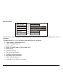
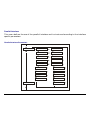
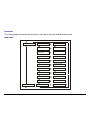
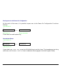
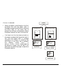
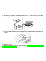
Safety Information A. Never remove any printer cover unless it is necessary for the installation of a printer accessory and expressly described in this manual. B. Please retain the printer covers in a safe place because they should be reinstalled if you decide to remove any printer accessory. The following areas of the printer should be covered for safety reasons: R ear Tracto r A re a C ove r A S F In stalla tion A rea C overs Tra ctor Fixin g Area C overs The above openings must always be protected with their cover when the corresponding option is not installed. Do not touch inside and do not insert any object into these openings or into the gears. iii FCC Notes This equipment has been tested and found to comply with the limits for a Class B digital device, pursuant to Part 15 of the FCC Rules. These limits are designed to provide reasonable protection against harmful interference when the equipment is operated in a commercial environment. This equipment generates, uses and can radiate radio frequency energy and, if not installed and used in accordance with the instruction manual, may cause harmful interference to radio communications. However, there is no guarantee that interference will not occur in a particular installation. If this equipment does cause harmful interference to radio or television reception, which can be determined by turning the equipment off and on, the user is encouraged to try to correct the interference by one or more of the following measures: • Reorient or relocate the receiving antenna. • Increase the separation between the equipment and the receiver to outlets on different circuits. • Consult the dealer or an experienced radio/TV technician for help. Changes or modifications not expressly approved by the party responsible for compliance could avoid the user's authority to operate the equipment. The use of a non-shielded interface cable with the referenced device is prohibited. The length of the parallel interface cable must be 3 meters (10 feet) or less. The length of the serial interface cable must be 15 meters (50 feet) or less.. Canadian D.O.C. Radio Interference Regulation This digital apparatus does not exceed the Class B limits for radio noise emission from digital apparatus as set out in the radio interference regulations of the Canadian Department of Communications. Le présent appareil numérique n'émet pas de bruits radioélectriques dépassant les limites applicables aux appareils numériques de classe A prescrites dans le règlement sur le brouillage radioélectrique édicté par le ministère des communications du Canada . EEC Regulations This equipment conforms to the EEC Directive 89/392 (the sound pressure, measured according to ISO 7779, does not exceed 70 dBA). Table of Contents Selection of the Paper Size.......................................................88 Adjusting the Tear-Off Position ..............................................89 Selection of the Tear-Off Mode................................................90 How to Lock/Unlock the Access to the Printer Setups .............91 How to Handle the Paper Parking..............................................92 Safety Information......................................................... iii FCC Notes...................................................................... iv Canadian D.O.C. Radio Interference Regulation.......................iv EEC Regulations............................................................................iv Table of Contents........................................................... v Getting to Know Your Printer ....................................... 1 Paper Handling............................................................. 97 Paper Paths ...................................................................................97 Paper Specifications .....................................................................98 Fanfold Paper (9058 and 9058D models) ...............................98 Envelopes (9058 model only) ...................................................98 Cut Sheets (9058 model only)..................................................99 Cut Sheets ...................................................................................100 Cut Sheets Loading Modes ....................................................100 Loading Cut Sheets.................................................................101 Fanfold Paper..............................................................................103 Loading Paper Using the Lower Tractor..............................103 Loading Paper Using the Upper Tractor..............................110 Loading Paper Using the Lower Push Tractor and the Rear Pull Tractor (option)................................................................115 Printer Features..............................................................................1 Unpacking Your Printer.................................................................2 Printer Parts....................................................................................3 Front View ...................................................................................3 Rear View.....................................................................................5 Setting Up Your Printer ................................................. 6 Choosing a Suitable Location ........................................................6 Printer Assembly ............................................................................7 Removal of the Shipment Locks................................................7 Ribbon Cartridge Installation....................................................8 Upper Push Tractor Installation (9058D model only) ..........13 Host Computer Connection .........................................................15 Software Driver Selection ............................................................16 Power Connection .........................................................................17 Printer Maintenance and Troubleshooting.............. 118 Cleaning the Printer...................................................................118 Replacing the Ribbon Cartridge................................................119 Printing the Self Test .................................................................120 Error Handling............................................................................121 Selecting the Display Language ................................. 19 Configuring the Printer................................................ 20 Operator Panel Presentation.......................................................20 Display Messages......................................................................21 Indicators ...................................................................................25 Function Keys............................................................................26 Printer Setups ...............................................................................31 Entering the Printer Setups ....................................................31 Moving within the Printer Setups...........................................31 Leaving the Printer Setups......................................................32 Power-On Configuration ..............................................................33 Entering the Power-On Configuration ...................................33 Program Setup ..............................................................................64 Entering the Program Setup....................................................64 How to Select the Paper Path......................................................87 How to Use the Tear-Off Function..............................................88 Options ....................................................................... 125 The Rear Pull Tractor ................................................................125 Installing the Rear Pull Tractor............................................125 Removing the Rear Pull Tractor ...........................................127 Automatic Sheet Feeder (ASF) ................................. 128 Color Kit.......................................................................................129 Pedestals......................................................................................130 Printer Specifications ................................................ 131 v Getting to Know Your Printer Printer Features • 24 Needle Print Head • 136 columns • Draft printing at 480 cps, LQ printing at 133 cps • IBM Proprinter XL24E/XL24AGM, Personal Printer 2391+ and EPSON LQ 1050-2550 (ESC /P) emulations • Multiple copies (1 original and 7 copies) • Automatic paper path selection • Easy operability via operator panel menu and S/W commands • Optional Automatic Sheet Feeder (120 sheets capability) which handles cut sheets, multicopies and envelopes, accepts up to two additional paper bins and includes paper stacker • Optional color kit • Usage of all specific features by means of the Specific Software Driver which is applicable to the most popular S/W Packages • Plug & Play capability for Windows 95/98/2000® • Bi-directional IEEE 1284 parallel interface and standard serial RS-232/C and RS-422/A interface. Automatic switching between the available interfaces. 1 Unpacking Your Printer Together with the Installation Guide and the CD-ROM with the User Manual, the following items are included in the box: Notify any damage to your supplier. Pow e r Ca ble Upp er P u sh Tractor (905 8D m odel on ly) Rib bon Cartridg e 2 Printer Parts Front View 9058 model O pe ra tor P anel Pa pe r Kno b C u t Sheet Support Po w er S w itch Pu sh Tractor C over Pa pe r G u ides 3 9058D model O pe ra tor P a ne l P a pe r K n o b P u sh Tracto rs C over P o w er S w itch 4 Rear View Top C o ve r R e ar P ap er S lo t R e ar Tracto r A rea C o ve r P a pe r K no b In te rfa ce C o nn ec to rs A S F A re a C ove r P o w er C ab le C o nn ec to r 5 R e ar Tracto r In s ta lla tion A re a C ove rs Setting Up Your Printer Choosing a Suitable Location Consider the following points when you choose the location for your printer: • The distance between the printer and the host computer must not exceed the length of the interface cable; • The location must horizontal and stable; be 80 cm 3 1 .5 in . sturdy, • Your printer must not be exposed to direct sunlight, extreme heat, cold, dust or humidity (see "Printer Specifications " later); 1 39 00 .4 cm in m 2 0 c in 7 .9 m 20 c in 7 .9 Additionally, you must make sure that when you install the printer in the selected location, there are sufficient clearances on all sides for easy operation. The required space is shown in the figure: 6 cm 0 in 1 0 .4 39 • You need an AC power outlet compatible with the plug of the printer's power cord. The voltage of the outlet must match the voltage shown on the printer's Rating Plate; Printer Assembly Removal of the Shipment Locks Open all the printer covers and make sure that you remove all the shipment locks from the printer. 7 Ribbon Cartridge Installation Two types of black ribbon cartridges are available for this printer, depending on whether the color kit is installed or not. Make sure that you are using only Compuprint original consumables. 1. Make sure that the printer is turned off. 2. Find the ribbon cartridge among the accessories. R ib b on gu id e R ib b on gu id e C o lo r K it G u id e Ten sion Kn ob Ten sion K n o b C artrid g e P in C a rtridg e P in to be used, when the color kit option is not installed to be used, when the color kit option is installed 8 3. Open the top cover using the small handles on either side of the top cover. 4. Turn the printer on. The print carriage prepares for ribbon cartridge installation. 9 5. Before installing the ribbon cartridge, turn the ribbon winding knob in the arrow direction (located on the cartridge) to take up slack in the ribbon. R ib b on Ten sion K n ob To avoid damage to the ribbon, do not turn the winding knob in the wrong direction. 6. Align the cartridge pins with the locking grooves on the left and right cartridge supports. The cartridge (black “Long Life” or color) to be used when the color kit is installed has only one groove. 10 7. Slide and insert the ribbon guide between the print head and the ribbon guide mask holding it perpendicular to the print head. Make sure that the ribbon is inserted correctly between the print head and the print head mask. 12 2. R ibbon G uide H older for C olor Kit If the color kit option is installed on your printer insert the white plastic holder onto the color kit as shown in the following figure. C olor Kit 11 8. Turn the ribbon winding knob in the arrow direction (located on the cartridge) to take up slack in the ribbon. R ib b on Ten sion Kn ob 9. Push the cartridge down gently until it clips into place at all four locking points. 10. Turn the ribbon winding knob again in the direction of the arrow to take up slack in the ribbon. 11. To ensure that the ribbon guide runs freely along the ribbon, manually move the print carriage horizontally. If you need to replace the used ribbon cartridge, see "Replacing The Ribbon Cartridge", later in this manual. 12 Upper Push Tractor Installation (9058D model only) An additional push tractor is provided with the 9058D printer. This second push tractor unit can be installed in front position (on the lower push tractor). 1. Find the upper push tractor among the accessories. 2. Install the upper push tractor aligning both its hooks with the lower push tractor pins and inserting them into the corresponding pins. Push the upper tractor until it is fully engaged. Insert the connector cable in the electrical connector located in the lower push tractor. Low e r Tractor Pin U p pe r Tractor H oo k Electrica l C onne ctor C o nn ecto r C able 13 3. The upper push tractor must be installed as shown in figure. 4. If you need to remove the upper push tractor, turn the printer off. Take the connector cable off and press on the push buttons (located in the upper push tractor hooks) to disengage the tractor. P u sh B utton 14 Host Computer Connection This printer can be connected to your host computer via two available interfaces. The interface connectors are located on the rear of the printer. • A bidirectional IEEE1284 parallel interface • A RS-232/C or RS-422/A serial interface Before connecting the interface cable, make sure that the printer and the host computer are turned OFF. Insert the parallel interface cable into the parallel connector and fasten it by means of the clips. Insert the serial interface cable into the serial connector, and fasten it by means of the two screws (use the screwdriver). Parallel interface Serial interface 15 Software Driver Selection At this point it is necessary to configure your printer for your application package. The installation procedures depend upon the host environment. Follow the instructions in the readme file you find on the CD-ROM. In a WINDOWS 95/98/2000® environment the printer supports the Plug & Play feature. The printer drivers of all Compuprint printers can be found at the Internet Address http://www.compuprint.net 16 Power Connection Make sure that the power outlet matches the power rating of the printer. See the name plate of the printer, that you find under the rear ASF cover. In case the power rating does not correspond DO NOT CONNECT THE PRINTER TO THE MAINS. Consult your dealer for help. 1. Make sure the power outlet is near the printer location and easily accessible. Always use a grounded outlet. 2. Make sure that the power switch is in 0 position (OFF). 17 3. Insert the power cable plug into the printer connector and the other power cable end into a convenient outlet (the figure shows the European version). 1 2 4. If you need to turn the printer on, press the power switch in the I position (ON). 18 Selecting the Display Language The display messages for this printer can be displayed in five different languages: English (Default), French, German, Italian and Spanish. To select the language, that you prefer, proceed as follows: 1. Press the PROGRAM key and keep it pressed while powering on the printer until the following message will be displayed: RELEASE KEY 2. When you release the PROGRAM key, the following messages will be displayed: 9058 9058D or then, PRINT OUT? NO 3. Press the ↓ key to enter the setup. The first setup item is displayed: PARALL INTERFACE 4. Press the ↓ key until the language first level function is displayed: FUNCTIONS 5. Press the → key to pass to the second level functions: PAPER OVERLY? NO for the 9058 model or SEQUENCE NONE for the 9058D model 6. Press the ↓ key until the setup language is displayed: MENU ENGLISH 7. Press the → key to scroll the setup languages. When the desired language is displayed, press the PROGRAM key to select it. The printer exits the setup. From now on the display messages appear in the selected language. 19 Configuring the Printer Operator Panel Presentation The operator panel enables you to perform many of the printer functions including paper path selections, font selection and the printer setup. R EAD Y L OAD /FF ↑ MIC R O F EED O N L IN E PROGRAM PITC H SH IFT SH IFT The operator panel consists of: • A 16 character display (Liquid Crystal Display) • Three function mode indicators • Seven function keys 20 LF ↓ ↑ PROGRAM ↑ QUIET MA CR O PAT H FO N T PAR K Display Messages The printer display is used to indicate the printer status or to request an user intervention and gives the following information: • when paper is already loaded and the printer is • off line (READY indicator unlit): M1 - Lower Push M1 - Lower Push E C urren t M a cro when paper is already loaded and the printer is on line (READY indicator lit): C u rre n t M a cro C urren t P a p er P a th C urren t E m ulation C u rre n t P a p er P a th where: M1, M2, M3, M4 Indicate which of the four User Macros is currently used. ASF1 ASF2 ASF3 LOWER PUSH UPPER PUSH PUSH PULL LOW.PUSH&MF PSH-PLL&MF MANUAL FORM Indicates which Paper Path is currently used. The printer displays only the messages related to the installed devices. E, I This acronym indicates the Emulation currently used. E indicates the EPSON emulation, whereas I indicates the IBM emulation. LOW.PUSH&MF: The lower push paper path and manual single sheet path are selected (9058 model only). PSH-PLL&MF: The push-pull paper path and manual single sheet path are selected (9058 model only). MANUAL FORM: The manual single sheet path is selected (9058 model only). 21 • when there is no paper loaded and the • printer is off line (READY indicator unlit): when there is no paper loaded and the printer is on line (READY indicator lit): M1 - Lower Push Load Lower Push C u rre n t M a cro C u rre n t P a p er P a th C u rre n t P a p er P a th where: M1, M2, M3, M4 Indicate which of the four User Macros is currently used. LOAD ASF1 LOAD ASF2 LOAD ASF3 LOAD LOWER PUSH LOAD UPPER PUSH LOAD LOW.PUSH&MF LOAD MANUAL FORM LOAD PSH-PLL&MF LOAD PUSH-PULL ASF1 ASF2 ASF3 LOWER PUSH UPPER PUSH PUSH-PULL LOW.PUSH&MF PSH-PLL&MF MANUAL FORM Indicates that the currently selected paper path is out of paper. The messages are displayed only for the available paper paths, according to the installed devices. Indicates which Paper Path is currently used. The printer displays only the messages related to the installed devices. LOW.PUSH&MF: The lower push paper path and manual single sheet path are selected (9058 model only). PSH-PLL&MF: The push-pull paper path and manual single sheet path are selected (9058 model only). MANUAL FORM: The manual single sheet path is selected (9058 model only). 22 The following messages appear to indicate other printer conditions or user intervention requests. The list is in alphabetical order: Message COVER OPEN CLOSE COVER EJECTING LOAD ASF1 LOAD ASF2 LOAD ASF3 LOAD LOWER PUSH LOAD LOW.PUSH&MF LOAD MANUAL FORM LOAD PSH-PLL&MF LOAD PUSH-PULL LOAD UPPER PUSH LOCKED MENU MACRO MICRO MICRO OPER. CHANGING FEED DOWN ↓ FEED UP ↑ INTERRUPTED PARKING PATH CHANGING PRESS A KEY NVM CHANGED Description When the printer cover is not closed correctly, the buzzer sounds and the display shows alternately these two messages. The printer is ejecting the paper out of the printer. These messages are displayed when the corresponding paper path is out of paper. The printer displays only the messages related to the installed devices. LOW.PUSH&MF = Lower push and manual paper path. PSH-PLL&MF = Push-Pull and manual paper path. When the access to the Printer Setups has been locked at the power on, the printer displays this message. The macro has been changed and the printer is updating the settings. The paper is fed in microsteps downwards when pressing the arrow key. The paper is fed in microsteps upwards when pressing the arrow key. This message is displayed if the SHIFT key has been pressed to interrupt a park procedure. The printer is parking the fanfold paper. The path has been changed and the printer is updating the settings. The NVM has been changed. Press any key to set the printer. 23 Message QUIET PRINT OFF QUIET PRINT ON RELEASE KEY RESET & BREAK SELF TEST SHIFT FUNCTION TEAR IF NECESS. PARK PAPER TEAR IF NECESS. EJECT PAPER TEAR OFF PAPER PARK PAPER TEAR OFF PAPER EJECT PAPER UNLOCKED MENU Description Printing at normal noise level. Printing at reduced noise level This message is displayed when you can release the PROGRAM key in the Self-test selection or in the Power-on Configuration procedure. When the input buffer is cleared an a break (250 msec.) on a serial interface is sent pressing the PROGRAM and then the ON LINE keys. The printer is printing the self-test page. This message appears to indicate that the Shift functions of the operator panel keys have been selected pressing the SHIFT key. These messages are displayed when the printer receives a paper parking command. Tear off the fanfold then press the PARK key to park the paper. These messages are displayed when the printer receives a paper parking command and the TEAR NO is selected for the tear-off function. Tear off the fanfold then press the PARK key to park the paper. These messages are displayed when the printer receives a paper parking command but was not able to execute it, because the paper to be parked is longer than 18 inch. Tear off the fanfold paper and then press the PARK key to park the paper. These messages are displayed when the printer receives a paper ejecting command (TEAR NO has been selected for the tear-off function) but was not able to execute it, because the paper to be ejected is longer than 18 inch. Tear off the fanfold paper and then press the PARK key to eject the paper. When the access to the Printer Setups has been unlocked at the power on, the printer displays this message. For the error messages see "Error Handling" later in this manual. 24 Indicators R EAD Y Lit when the printer can receive and print data (printer online). Blinks when there is data in the buffer and the printer is offline. Unlit, when the printer is disabled and the buffer does not contain any data, or during the initialization, setup or tests. PRO GRAM Blinks when one of the printer setup procedures has been selected: Program Configuration or Power-On Configuration. SH IFT Lit when the alternate function of the keys has been enabled pressing the SHIFT key. 25 Function Keys The function keys are enabled, when the printer is offline (READY indicator unlit). The function keys have three functions each. Normal Function The normal function of the keys does not require previous action to select it. This function is indicated in black characters beside the function keys. Shift Function The alternate function is selected pressing the SHIFT key. The alternate functions of the keys are described on the gray areas beside the keys. The SHIFT indicator is lit and the display shows SHIFT FUNCTION. This function is not enabled, if the printer is in setup mode. Program Function The program function is selected pressing the PROGRAM key, where: • If you press the key while powering on the printer, the Power-On Configuration is selected. • Pressing the key when the printer is enabled without printing or disabled (READY indicator unlit), the Program Setup is selected. In the Program Setup mode only the four arrow keys and the PROGRAM key are enabled. When the printer is in setup mode, the PROGRAM indicator blinks. 26 ON LINE Key ON LINE Normal Function Program Function Enables or disables the printer. • If this key is pressed while powering the printer on, the self test is printed; the printout is stopped pressing this key again. • In an error condition, once the error cause has been removed, press this key to enable the printer. • If the Tear-Off Function in the Program Setup is set to Manual, press this key to position the paper for the Tear-Off. Pressing this key, the input buffer is cleared an a break (250 msec.) on a serial interface is sent. The message RESET & BREAK is displayed. PROGRAM Key PROGRAM PITCH Normal Function Enables the printer setups as follows: • Pressing this key while powering on the printer, the Power-On Configuration is selected. • Pressing this key when the printer is enabled without printing or disabled (READY indicator unlit), the Program Setup is enabled. Shift Function Selects the pitch to be used with the currently selected font. The selected pitch is valid until the printer is turned off. Program Function Exits the current printer setup. See also “Leaving the Printer Setups”, later in this section. 27 SHIFT Key SHIFT Normal Function Enables the alternative key functions. If the printer is receiving print data, press the ON LINE key before pressing the SHIFT key. If no printing data are in the print buffer, pressing the SHIFT key, the printer goes offline. The display then shows SHIFT FUNCTION to indicate that the Shift Function of the keys is enabled. May be used to abort paper parking procedure. See also “How to Handle the Paper Parking”, later in this manual. Shift Function Disables the alternative key functions. If pressed after the PARK key, the parking procedure is interrupted. LOAD/FF Key LOAD/FF Normal Function Executes a Form Feed (FF): when paper is loaded into the printer, it advances to the following page; if no paper is loaded, it is positioned for printing. ↑ Shift Function Moves the paper forward in microsteps. Keeping the key pressed the paper is moved continuously at increasing speed. ↑ Program Function Scrolls the parameters of the functions or macros backwards. 28 LF Key LF Normal Function Performs a line feed according to the current line spacing settings. ↓ Shift Function Moves the paper backward in microsteps. Keeping the key pressed the paper is moved continuously at increasing speed. ↓ Program Function Scrolls the setup and macro functions forward. MACRO Key MACRO PATH ← Normal Function Selects one of the user macros (Macro 1, Macro 2, Macro 3 or Macro 4). If you want to select the displayed macro, wait for 2 seconds without pressing any key and the parameters of this macro will be set . Shift Function Selects one of the paper paths. The parameters of the displayed path are set pressing the SHIFT key or waiting for 2 seconds without pressing any key. Program Function Scrolls the setup and macro functions backward. Normal Function Selects the font to be used with the currently selected pitch. The selected font is valid until the printer is turned off. FONT Key FONT PARK → Shift Function Parks the paper in the currently selected paper path. Program Function Scrolls the setup and macro functions forward. 29 Key Combinations PROGRAM + SHIFT Normal Function ONLINE + MACRO + SHIFT Normal Function When the printer is on line without printing or printing data (READY indicator lit) or when the printer is unable to receive and print data but there is still data in the input buffer (READY indicator blinks) press these two keys contemporaneously, the printing noise level toggles between normal (QUIET PRINT OFF) and reduced noise level (QUIET PRINT ON). When the printer is off line (READY indicator unlit), the printing noise level function is disabled. Lock or unlock the access to the printer setups. See later “How to Lock/Unlock the Access to the Printer Setups” section. 30 Printer Setups The main printer setup parameters can be selected via the operator panel. The setup parameters are divided into two printer setups, the Power-On Configuration, that allows a complete configuration at installation time according to the hardware and the emulation types, and the Program Setup, that allows you to set the functions that are the most useful in your daily job. This settings can be selected when the printer is online without printing or offline (READY indicator unlit). These settings can be stored in the NVM. Entering the Printer Setups • Press the PROGRAM key and keep it pressed at the printer power on until the RELEASE KEY message is displayed to select the Power-On Configuration. • Press the PROGRAM key when the printer is online without printing or offline (READY indicator unlit) to select the Program Setup. Moving within the Printer Setups The arrow keys ↑, ↓, ← , → are used to move within the different functions inside the Printer Setups. See the following description of the setup items. 31 Leaving the Printer Setups • Pressing the PROGRAM key in the Power-On Configuration the printer exits from the setup and the new settings will be automatically saved. • Pressing the PROGRAM key in the Program Setup, the following choice is offered to store the values set: STORE? QUIT The new settings are not activated and the old settings remain valid. STORE? SAVE The new settings are stored permanently in the NVM (Non Volatile Memory). STORE? CURRENT The new settings remain valid until the printer is turned off. Press the → or ← keys to scan these selections forward and backwards. When the desired setting is displayed, press the PROGRAM key to exit from the Setup. 32 Power-On Configuration The default values of the various functions are indicated in bold. Entering the Power-On Configuration 1. Make sure that the printer is turned off. 2. Press and hold the PROGRAM key pressed while powering on the printer until the RELEASE KEY message is displayed. As soon as the PROGRAM key gets released, the following message will be displayed: or 9058 9058D then, PRINT OUT? NO The following figure shows the structure of the Power-On Configuration and how to move inside the Setup. 33 Main Structure P rint ou t? N O P rint ou t? Y E S P arall Interface P arallel Interface S ettings S erial Interface S erial Interface Settin gs Fu nctions Fu nctions B lo ck B ack to M F G ? N O B ack to M F G ? Y ES The functions concerning the interfaces group the parameters for the configuration of the interfaces. The setup item Functions groups the following printer functions: • • • • • • • • • • • Paper overlay (9058 model only), Paper loading sequence, Buzzer setting, Quick cut sheet loading (9058 model only), Ribbon type, Code bar density, Text printing direction, Graphics printing direction, Bar code printing direction, Paper path at power on, Language of the display messages. 34 Printout of the Printer Settings PRINT OUT? NO → or ← PRINT OUT? YES ↓ PARALL INTERFACE PRINT OUT? NO The Setup is not printed. PRINT OUT? YES The printer setup is printed showing the currently selected values. The printout starts as soon as you select this value. 35 Parallel Interface This menu defines the use of the parallel interface and is structured according to the interface specific parameters. Parallel Interface Parameters P arall.Interface 1284 B idir. I/F C X Parallel I/F S elect-In H ost S elect-In O n D ata Bits 8 D ata Bits 7 D edic. Buffer 2K D edic. Buffer ... E m ul EP SO N E m ul. IBM ... C har. S et ... C har. S et ... N ation ... N ation ... A uto C R ... A uto C R ... A uto L F ... A uto L F ... S erial Interface 20 C P I IBM ... 36 Setting the Interface Parameters Interface Type PRINT OUT? NO PARALL INTERFACE ↓ ↑ PARALL INTERFACE → 1284 BIDIR I/F → or ← CX PARALLEL I/F → or ← ↓ ↓ SERIAL INTERFACE SELECT-IN HOST 1284 BIDIR I/F Bidirectional IEEE 1284 parallel interface. CX PARALLEL I/F Centronics type parallel interface (monodirectional) Setting the Select-In Signal 1284 BIDIR. I/F ↑ SELECT-IN HOST → or ← SELECTIN ON → or ← ↓ DATA BITS 8 SELECT-IN ON The SELECT-IN signal of the parallel interface is ignored and treated always as ON. SELECT-IN HOST The printer checks the SELECT-IN signal coming from the host. 37 Number of Data Bits SELECT-IN HOST ↑ DATA BITS 8 → or ← DATA BITS 7 → or ← ↓ DEDIC.BUFFER 2K Selection of the number of data bits: 7 or 8 Input Buffer Size DATA BITS 8 ↑ DEDIC.BUFFER 256 → or ← DEDIC.BUFFER 2K → or ← DEDIC.BUFFER 12K → or ← DEDIC.BUFFER 32K → or ← ↓ EMUL. EPSON LQ Selects the input buffer size. For the DLL the input buffer must be set to 2K. 38 Printer Emulation DEDIC.BUFFER 2K ↑ EMUL. EPSON LQ → or ← EMUL. IBM XL24 → or ← EMUL. IBM XL24AGM → or ← EMUL. IBM 2391 → or ← ↓ CHAR. SET CS2 EMUL. EPSON LQ The printer uses the EPSON LQ 1050/2550 emulation. EMUL. IBM XL24 The printer uses the IBM Proprinter XL24e emulation. EMUL. IBM XL24AGM The printer uses the IBM Proprinter XL24 AGM emulation. EMUL. IBM 2391 The printer uses the IBM Personal 2391+ emulation. EPSON Character Sets EMUL. EPSON LQ ↑ CHAR. SET CS1 → or ← CHAR. SET CS2 → or ← CHAR. SET ITALIC → or ← ↓ NATION CP437 These items select the character set to be used in EPSON emulation. 39 IBM Character sets EMUL. IBM xxx ↑ CHAR. SET CS1 → or ← CHAR. SET CS2 → or ← ↓ NATION CP437 These items select the character set to be used in IBM Proprinter emulation. EPSON National Character sets CHAR. SET CS2 ↑ NATION CP437 → or ← NATION ... → or ← NATION LATIN A1 → or ← ↓ AUTO CR YES The following national character sets are available: CP 437 CP437 G 96 GREEK CP850 CP851 CP 852 CP 853 CP 855 CP 857 CP 858 CP 860 CP 862 CP 863 CP 864 CP 865 CP 866 CP 867 CP 876 CP 877 CP 1250 CP 1251 CP 1252 GOST TASS MAZOWIA ISO 8859/1 ISO 8859/2 ISO 8859/3 ISO 8859/4 ISO 8859/5 ISO 8859/6 ISO 8859/7 ISO 8859/8 ISO 8859/9 ISO 8859/15 USA FRANCE GERMANY ENGLAND DENMARK1 SWEDEN ITALY NORWAY DENMARK2 SPAIN2 LATIN A1 SPAIN1 JAPAN The CP 858 and ISO 8859/15 character sets contain the Euro character. 40 IBM National Character Sets CHAR. SET CS2 ↑ NATION CP437 → or ← NATION ... → or ← NATION 8859/15 → or ← ↓ AUTO CR YES The following national character sets can be selected: CP 437 CP437 G 96 GREEK CP850 CP851 CP 852 CP 853 CP 855 CP 857 CP 858 CP 860 CP 862 CP 863 CP 864 CP 865 CP 866 CP 867 CP 876 CP 877 CP 1250 CP 1251 CP 1252 GOST TASS MAZOWIA ISO 8859/1 ISO 8859/2 ISO 8859/3 ISO 8859/4 ISO 8859/5 ISO 8859/6 ISO 8859/7 ISO 8859/8 ISO 8859/9 ISO 8859/15 The CP 858 and ISO 8859/15 character sets contain the Euro character. 41 CR Code Behavior NATION xxx ↑ → or ← → or ← AUTO CR NO AUTO CR YES ↓ AUTO LF NO AUTO CR NO No automatic carriage return is performed after a LF, VT or ESCJ code. AUTO CR YES The printer performs an automatic carriage return after a LF, VT or ESCJ code . LF Code Behavior AUTO CR YES ↑ AUTO LF NO AUTO LF YES AUTO LF HOST → or ← → or ← → or ← ↓ 20 CPI IBM NO or PARALL INTERFACE AUTO LF NO No Automatic LF after CR. AUTO LF YES Automatic LF after CR. AUTO LF HOST Only in EPSON emulation. The printer checks the AUTOFEEDXT signal coming from the host and executes an automatic LF after CR, if the signal is low. 42 IBM Compressed Printing These items are displayed only, if the IBM emulation is selected. AUTO LF NO ↑ 20 CPI IBM NO → or ← 20 CPI IBM YES → or ← ↓ PARALL INTERFACE 20 CPI IBM NO The compressed printing is performed at 17,1 cpi. 20 CPI IBM YES The compressed printing is performed at 20 cpi. 43 Serial Interface This menu defines the use of the serial interface and is structured according to the interface specific parameters. Serial Interface Parameters S erial Inte rface S erial I/F N o S erial I/F ... B aud 9600 B aud ... D ata Bits 8 D ata Bits 7 P arity N on e P arity ... H and sh ake D TR H and sh ake X on /Xof C onn ectio n L ocal C onn ect. R emo te D edic. B uffer 2K D edic. B uffer ... E m ul. E P S O N E m ul. IB M ... C har. S et ... C har. S et... Nation ... N ation ... A uto CR ... A uto CR ... A uto L F … A uto L F ... 20 CP I IBM ... Fu nctions 44 Setting the Interface Parameters Interface Type PARALL INTERFACE SERIAL INTERFACE ↑ ↑ SERIAL INTERFACE ↓ FUNCTIONS → SERIAL I/F NO → or ← SERIAL I/F 232 → or ← SERIAL I/F 422 → or ← ↓ BAUD 9600 SERIAL I/F NO The serial interface is disabled SERIAL I/F 232 Defines the usage of the serial interface RS-232/C SERIAL I/F 422 Defines the usage of the serial interface RS-422/A 45 Baud Rate SERIAL I/F NO ↑ BAUD 300 → or ← BAUD 600 → or ← BAUD 1200 → or ← BAUD 2400 → or ← BAUD 4800 → or ← BAUD 9600 → or ← BAUD 19200 → or ← BAUD 38400 → or ← ↓ DATA BITS 8 The baud rate is selected in bits per second. The above values can be selected. Number of Data Bits BAUD 9600 ↑ DATA BITS 8 → or ← DATA BITS 7 → or ← ↓ PARITY NONE Selection of the number of data bits: 7 or 8. 46 Parity Check DATA BITS 8 ↑ PARITY NONE → or ← PARITY ODD → or ← PARITY EVEN → or ← PARITY MARK → or ← PARITY SPACE → or ← ↓ HANDSHAKE DTR PARITY NONE Data does not have a parity bit, i.e. 8 bit data are transferred and the parity check is disabled. PARITY ODD Parity check is enabled for odd parity. PARITY EVEN Parity check is enabled for even parity. PARITY MARK Parity check is disabled and the transmitted parity bit is always a Mark. PARITY SPACE Parity check is disabled and the transmitted parity bit is always a Space. 47 Handshake Protocol PARITY NONE ↑ HANDSHAKE DTR → or ← HANDSHAKE XONXOF → or ← ↓ CONNECTION LOCAL HANDSHAKE DTR The Handshake is performed using the DTR Protocol. HANDSHAKE XONXOF The Handshake is performed using the XON-XOFF Protocol. Connection Type HANDSHAKE DTR ↑ CONNECTION LOCAL → or ← CONNECT. REMOTE → or ← ↓ DEDIC.BUFFER 2K Selects the connection type: local or remote. 48 Input Buffer Size CONNECTION LOCAL ↑ DEDIC.BUFFER 256 → or ← DEDIC.BUFFER 2K → or ← DEDIC.BUFFER 12K → or ← DEDIC.BUFFER 32K → or ← ↓ EMUL. EPSON LQ Selects the input buffer size. For the DLL the input buffer must be set to 2K. Printer Emulation DEDIC.BUFFER 2K ↑ EMUL. EPSON LQ → or ← EMUL. IBM XL24 → or ← EMUL. IBM XL24AGM → or ← EMUL. IBM 2391 → or ← ↓ CHAR. SET CS2 EMUL. EPSON LQ The printer uses the EPSON LQ 1050/2550 emulation. EMUL. IBM XL24 The printer uses the IBM Proprinter XL24e emulation. EMUL. IBM XL24AGM The printer uses the IBM Proprinter XL24 AGM emulation. EMUL. IBM 2391 The printer uses the IBM Personal 2391 + emulation. 49 EPSON Character Sets EMUL. EPSON LQ ↑ CHAR. SET CS1 → or ← CHAR. SET CS2 → or ← CHAR. SET ITALIC → or ← ↓ NATION CP437 These items select the character set to be used in EPSON emulation. IBM Character sets EMUL. IBM xxx ↑ CHAR. SET CS1 → or ← CHAR. SET CS2 → or ← ↓ NATION CP437 These items select the character set to be used in IBM Proprinter emulation. 50 EPSON National Character sets CHAR. SET CS2 ↑ NATION CP437 → or ← NATION ... → or ← NATION LATIN A1 → or ← ↓ AUTO CR YES The following national character sets are available: CP 437 CP437 G 96 GREEK CP850 CP851 CP 852 CP 853 CP 855 CP 857 CP 858 CP 860 CP 862 CP 863 CP 864 CP 865 CP 866 CP 867 CP 876 CP 877 CP 1250 CP 1251 CP 1252 GOST TASS MAZOWIA ISO 8859/1 ISO 8859/2 ISO 8859/3 ISO 8859/4 ISO 8859/5 ISO 8859/6 ISO 8859/7 ISO 8859/8 ISO 8859/9 ISO 8859/15 USA FRANCE GERMANY ENGLAND DENMARK1 SWEDEN ITALY NORWAY DENMARK2 SPAIN2 LATIN A1 SPAIN1 JAPAN The CP 858 and ISO 8859/15 character sets contain the Euro character. 51 IBM National Character Sets CHAR. SET CS2 ↑ NATION CP437 → or ← NATION ... → or ← NATION 8859/15 → or ← ↓ AUTO CR: YES The following national character sets can be selected: CP 437 CP437 G 96 GREEK CP850 CP851 CP 852 CP 853 CP 855 CP 857 CP 858 CP 860 CP 862 CP 863 CP 864 CP 865 CP 866 CP 867 CP 876 CP 877 CP 1250 CP 1251 CP 1252 GOST TASS MAZOWIA ISO 8859/1 ISO 8859/2 ISO 8859/3 ISO 8859/4 ISO 8859/5 ISO 8859/6 ISO 8859/7 ISO 8859/8 ISO 8859/9 ISO 8859/15 The CP 858 and ISO 8859/15 character sets contain the Euro character. 52 CR Code Behavior NATION xxx ↑ AUTO CR NO → or ← AUTO CR YES → or ← ↓ AUTO LF NO AUTO CR NO No automatic carriage return is performed after a LF, VT or ESCJ code. AUTO CR YES The printer performs an automatic carriage return after a LF, VT or ESCJ code . LF Code Behavior AUTO CR YES ↑ AUTO LF NO AUTO LF YES → or ← → or ← ↓ 20 CPI IBM NO or SERIAL INTERFACE AUTO LF NO No Automatic LF after CR. AUTO LF YES Automatic LF after CR. 53 IBM Compressed Printing These items are displayed only, if the IBM emulation is selected. AUTO LF:NO ↑ 20 CPI IBM NO → or ← 20 CPI IBM YES → or ← ↓ SERIAL INTERFACE 20 CPI IBM NO The compressed printing is performed at 17,1 cpi. 20 CPI IBM YES The compressed printing is performed at 20 cpi. 54 Functions This item groups various printer functions, with which you can configure the printer. 9058 model Fu nctions P aper O verly? N o S eque nce N o ne S eque nce ... B uzzer Yes B uzzer No Q u ick N o Q u ick Yes B ack to Mfg? N o P aper O verly? Yes R ib bon Black R ib bon C olor B ar C odes 60 B ar C odes 90 Text D irect B i Text D irect U ni G rap h D irect B i G rap h D irect U ni B arcodes D ir. U ni B arcodes D ir. B i P.O n Path M acro P.O n Path Last M enu E N G LIS H M enu … 55 9058D model Functions Back to Mfg? No Sequence None Sequence ... Buzzer Yes Buzzer No Ribbon Black Ribbon Color Bar C odes 60 Bar C odes 90 Text Direct Bi Text Direct U ni Graph D irect Bi Graph D irect Uni Barcodes Dir. Uni Barcodes Dir.Bi P.On Path Macro P.On Path Last M enu ENGLISH M enu … 56 Setting the Functions Group Items SERIAL INTERFACE FUNCTIONS ↑ ↑ FUNCTIONS → ↓ PAPER OVERLY NO 9058 SEQUENCE NONE 9058D ↓ BACK TO MFG: NO SEQUENCE NONE or BUZZER YES 9058 9058D Paper Overlapping (9058 model only) FUNCTIONS ↑ PAPER OVERLY NO → or ← PAPER OVERLY YES → or ← ↓ SEQUENCE NONE PAPER OVERLY NO When feeding a cut sheet through the manual entry slot, the fanfold paper must be parked. PAPER OVERLY YES A single sheet can be fed simultaneously with a fanfold. If the printer is using the Push Pull paper feed mode the Overlay Function cannot be selected. Only the Paper Overly No item appears. 57 Paper Loading Sequence FUNCTIONS (9058D model) or PAPER OVERLY NO (9058 model) ↑ SEQUENCE NONE → or ← SEQ. L + U PUSH (9058D model only) → or ← SEQUENCE ASF1+2 → or ← SEQUENCE ASF123 → or ← ↓ BUZZER YES These items are displayed only, if the accessories to which they refer are installed. SEQUENCE NONE The paper is fed only through the path selected by operator panel. SEQ. L + U PUSH The paper is fed firstly through the lower push path and successively through the upper push path (9058D model only). SEQUENCE ASF1+2 This item appears only, if the automatic sheet feeder is installed. The paper is fed from the first bin until this bin is out of paper. Then the paper is fed from the second bin. SEQUENCE ASF123 This item appears only, if the automatic sheet feeder is installed. The paper is fed from the first bin until this bin is out of paper. Then the paper is fed from the second bin and finally from the third bin. 58 Enable/Disable the Buzzer SEQUENCE NONE ↑ BUZZER YES → or ← BUZZER NO → or ← ↓ QUICK YES (9058 model) or BLACK RIBBON (9058D model) Enable or disables the buzzer. Quick Manual Loading through the Manual Slot (9058 model only) BUZZER YES ↑ QUICK NO → or ← QUICK YES → or ← ↓ RIBBON BLACK QUICK NO The single sheet in the manual path is loaded by the operator. The printer is then disabled. QUICK YES The single sheet in the manual path is loaded automatically. The printer is then enabled. 59 Ribbon Type Selection QUICK YES (9058 model) or BUZZER YES (9058D model) ↑ RIBBON BLACK → or ← RIBBON COLOR → or ← ↓ BAR CODE 60DPI Selects the ribbon type to be used with the printer: black or color. Bar Code Density RIBBON BLACK ↑ BAR CODE 60DPI → or ← BAR CODE 90DPI → or ← ↓ TEXT DIRECT BI Selects the bar code print density: 60 or 90 dpi. Text Print Direction BAR CODE 60DPI ↑ TEXT DIRECT BI → or ← TEXT DIRECT UNI → or ← ↓ GRAPH DIRECT BI Selects the print direction for text: bidirectional or unidirectional. 60 Graphics Print Direction TEXT DIRECT BI ↑ GRAPH DIRECT BI → or ← GRAPH DIRECT UNI → or ← ↓ BARCODES DIR.UNI Selects the print direction for graphics: bidirectional or unidirectional. Bar Codes Print Direction GRAPH DIRECT BI ↑ BARCODES DIR.BI → or ← BARCODES DIR.UNI → or ← ↓ P. ON PATH MACRO Selects the print direction for bar codes: bidirectional or unidirectional. 61 Paper Path at Power-On BARCODES DIR.UNI ↑ P. ON PATH MACRO → or ← P. ON PATH LAST → or ← ↓ MENU ENGLISH P. ON PATH MACRO The paper path at power-on is the one from the default Macro. P. ON PATH LAST The paper path at power-on is the last one that was selected before the printer was powered off. Selection of the Language of the Display Messages P. ON PATH MACRO ↑ MENU ENGLISH → or ← MENU ITALIANO → or ← MENU FRANCAIS → or ← MENU ESPANOL → or ← MENUE DEUTSCH → or ← ↓ FUNCTIONS These items are self explaining. See also “Selecting the Display Language” before in this manual. 62 Resetting to Factory Default Values With the BACK TO MFG function it is possible to reset all items in the Power On Configuration and in the Program Setup to their factory default values. This may be useful if you do not remember the values you set in the menus, or because you simply changed you mind about the settings you have just done. The default values for the menu items are indicated in bold FUNCTIONS ↑ BACK TO MFG: NO → or ← BACK TO MFG: YES ↓ or PROG PRINT OUT ? NO If you want to select BACK TO MFG:YES, you have to exit from this item using the ↑ or the ↓ key, in order to confirm the selection of this value. At this point, the Power On Configuration Setup procedure is finished. If you exit pressing the ↓ and the PROGRAM key, the new settings will be saved. Do not power off the printer before all data have been written into the NVM and the printer has returned online. 63 Program Setup The default values of the various functions are indicated in bold. Entering the Program Setup Press the PROGRAM key when the printer is turned on and is offline or online without printing. The following message will be displayed: PRINT OUT? NO The following figure shows the structure and how to move inside the Program Setup. 64 Main Structure P rin t ou t? N o P rin t ou t? Ye s U se r M a cro M acro # 1 Lin e sp . 6 lp i ... … Lin e sp . ... M A C R O PA R A M ET ER B L OC K N ex t M a cro ? N o C on fig. M e n u N o C on fig. M e n u Yes H ex D u m p N o H ex D u m p Ye s Te a r a d ju st: 0 Te a r a d ju st: … N ex t M a cro ? Ye s The items define the following parameters: • Four user macros • The direct access to the Power-On Configuration • Hexadecimal printout • Tear-Off adjustment 65 M acro # 4 Printout of the Printer Settings PRINT OUT? NO → or ← PRINT OUT? YES ↓ USER MACRO PRINT OUT? NO The Setup is not printed. PRINT OUT? YES The printer setup is printed. The printout starts as soon as you select this value. NOTE: The Program setup printout indicates: • the currently selected values, • the current selected macro is marked with the #x# symbols (USER MACRO #x#), • the current firmware release. 66 USER MACRO The USER MACRO item allows to prepare four printing environments (MACRO#1, MACRO#2, MACRO#3 and MACRO#4). Each macro is composed of a group of parameters which define a configuration that can then be recalled to easily set the printer for four printing environments. SELECTION OF THE USER MACRO PRINT OUT? NO USER MACRO ↓ ↑ USER MACRO ↓ CONFIG MENU NO → MACRO # 1 → or ← MACRO # 2 → or ← MACRO # 3 → or ← MACRO # 4 → or ← ↓ LINE SP. 6 LPI Selection of the macro for which you intend to set the parameters. When a new macro is selected and the fanfold paper is present in the paper path set in the previous macro, it will be automatically parked (TEAR IF NECESS./PARK PAPER is displayed). Tear off this fanfold paper to avoid paper jams and press PARK key. 67 USER MACRO PARAMETERS U ser m acro M acro # 1 M acro #2 M acro # 3 M acro #4 Lin e sp. 6 lpi Lin e sp. ... Lin e sp. Lock N o Lin e sp. Lock Yes Len gth 1 Line Len gth ... Top of F orm 0 Top of F orm ... S kipover 0 S kipover … Fo nt D raft Fo nt … P itch 10 cpi P itch … P itch Lo ck N o P itch Lo ck Yes Left M argin 0 Left M argin … 68 R ig ht M argin 2 R ig ht M argin … S lash Zero N o S lash Zero Yes P ath Low er P ush P ath ... Tear norm al Tear … . S tron g im pact S oft im pact P erfo r. S afe N o P erfo r. S afe Yes A utogap 0 A utogap ... Tuning: H oriz 0 Tuning: H oriz ... Tuning: Vert 0 Tuning: Vert ... M acro-> M F G N o M acro-> M F G Yes N ext m acro? N o N ext m acro? Yes C onfig. M enu N o 69 Line Spacing MACRO # 1 ↑ MACRO# 1 → LINE SP. 6 LPI → or ← LINE SP. 8 LPI → or ← LINE SP. 12 LPI → or ← LINE SP 3L/30MM → or ← LINE SP 4L/30MM → or ← LINE SP 6L/30MM → or ← LINE SP 8L/30MM → or ← LINE SP 12L/30MM → or ← ↓ LINE SP LOCK NO These values define the line spacing in lines/inch (6, 8, 12) or in lines per 30 mm (3, 4, 6, 8, 12). Line Spacing Lock LINE SP. 6 LPI ↑ LINE SP. LOCK NO → or ← LINE SP. LOCK YES → or ← ↓ LENGTH xxx LINE SP. LOCK NO Setting this item, the value set for vertical spacing can be changed by software or operator panel. LINE SP. LOCK YES Setting this item, the value set for vertical spacing cannot be changed by software but only by operator panel. 70 Page Length LINE SP. LOCK NO ↑ LENGTH 1 LINE → or ← LENGTH . .. LINES → or ← LENGTH 244 LINES → or ← LENGTH A5 → or ← LENGTH A4 → or ← LENGTH A3 → or ← LENGTH A2 → or ← LENGTH LEGAL → or ← LENGTH LETTER → or ← ↓ TOP OF FORM 0 These items set the page length for fanfold paper in number of lines depending on the current vertical spacing. For the single sheets the page format can be specified in number of lines or the standard formats LETTER, LEGAL, A2, A3, A4, A5. Default value is 66 lines. 71 Top of Form LENGTH Xx ↑ TOP OF FORM 0 → or ← TOP OF FORM ... → or ← TOP OF FORM xxx → or ← ↓ SKIPOVER 0 These items set the top of form. The values range between 0 and the page length - 1. Skip Over Perforation TOP OF FORM 0 ↑ SKIPOVER 0 → or ← SKIPOVER ... → or ← SKIPOVER xxx → or ← ↓ FONT Draft These items set the skipover perforation. The values range between 0 and the page length - 1. 72 Font Selection SKIPOVER 0 ↑ FONT Draft → or ← FONT Courier → or ← FONT OCR-B → or ← FONT Gothic → or ← FONT Prestige → or ← FONT Presentor → or ← FONT Script → or ← FONT OCR-A → or ← FONT Boldface → or ← ↓ PITCH 10 CPI Selects the fonts. OCR-A and OCR-B only if the pitch is set to 5 or 10 cpi. Boldface can be selected only if the proportional pitch has been selected (PITCH PROP). 73 Pitch Selection FONT Draft ↑ PITCH 5 CPI → or ← PITCH 6 CPI → or ← PITCH 7.5 CPI → or ← PITCH 8.5 CPI → or ← PITCH 10 CPI → or ← PITCH 12 CPI → or ← PITCH 15 CPI → or ← PITCH 17.1 CPI → or ← PITCH 20 CPI → or ← PITCH 24 CPI → or ← PITCH PROP → or ← ↓ PITCH LOCK NO These items set the horizontal spacing in characters per inch. The PROP item sets proportional character spacing. 74 Pitch Lock PITCH 10 CPI ↑ PITCH LOCK NO → or ← PITCH LOCK YES → or ← ↓ LEFT MARGIN 0 PITCH LOCK NO Setting this item, the pitch can be changed by software or operator panel. PITCH LOCK YES Setting this item, the pitch can be changed ONLY by operator panel. Left Margin PITCH LOCK NO ↑ LEFT MARGIN 0 → or ← LEFT MARGIN ... → or ← LEFT MARGIN xxx → or ← ↓ RIGHT MARGIN 136 The Left Margin is set in number of columns (depending on the current pitch) starting from the physical left edge. 75 Right Margin LEFT MARGIN 0 ↑ RIGHT MARGIN. 2 → or ← RIGHT MARGIN. ... → or ← RIGHT MARGIN. xxx → or ← ↓ SLASH ZERO NO The Right Margin is set in number of columns (depending on the current pitch) starting from the physical left edge. The default value is 136. Zero Character Printing RIGHT MARGIN 136 ↑ SLASH ZERO NO → or ← SLASH ZERO YES → or ← ↓ PATH LOWER PUSH You can select the Zero character printing with or without a slash. 76 Paper Path Selection This function defines the default paper path for the current macro. SLASH ZERO NO ↑ PATH LOWER PUSH → or ← PATH UPPER PUSH (9058D only) → or ← PATH MANUAL FORM (9058 only) → or ← PATH PUSH PULL → or ← PATH ASF1 → or ← PATH ASF2 → or ← PATH ASF3 → or ← ↓ TEAR NORMAL PATH LOWER PUSH Paper loading with the lower push tractor. PATH UPPER PUSH Paper loading with the upper push tractor (9058D model only). PATH MANUAL FORM Paper loading using the manual single sheet path (9058 model only). PATH PUSH PULL Paper loading using the lower push tractor and the rear pull tractor. PATH ASF1 Paper loading from the first bin of the ASF, if installed. PATH ASF2 Paper loading from the second bin of the ASF, if installed. PATH ASF3 Paper loading from the third bin of the ASF, if installed. 77 Tear-Off Mode PATH LOWER PUSH ↑ TEAR NORMAL → or ← TEAR AUTOMATIC → or ← LABEL → or ← TEAR NO → or ← ↓ STRONG IMPACT TEAR NORMAL The Tear-Off Function is performed pressing the ONLINE key when the printer is offline. TEAR AUTOMATIC When the printer is not receiving any data, the paper is moved to the Tear-Off position. It is returned to the Tear-Off position as soon as it receives printing data. LABEL This item must be set when printing on labels, in order to avoid paper jams. The paper does not execute any backward movement. When pressing the PARK key, the paper is ejected. TEAR NO The paper does not execute any backward movement. See also “How to Use the Tear-Off Function” later in this chapter. 78 Print Impact Strength TEAR NORMAL ↑ STRONG IMPACT → or ← SOFT IMPACT → or ← ↓ PERFOR. SAFE NO STRONG IMPACT The impact strength of the print head is set for printing on multicopy paper. SOFT IMPACT The impact strength of the print head is set for printing on single paper or few copies. The printing noise is reduced. Paper Perforation This function allows to move the print head aside the paper when the fanfold paper perforation passes between the mylar and the print bar, to avoid paper jams. If the use of single sheets is selected, this item is not displayed. STRONG IMPACT ↑ PERFOR. SAFE NO → or ← PERFOR. SAFE YES → or ← ↓ AUTOGAP 0 PERFOR. SAFE NO The function is disabled. The print head remains in its position, when the perforation of the paper passes. PERFOR. SAFE YES The function is enabled. The print head is moved aside, when the perforation passes. 79 Adjusting the Print Head Distance PERFOR. SAFE NO ↑ AUTOGAP -5 → or ← AUTOGAP ... → or ← AUTOGAP +3 → or ← MANUAL GAP → or ← FIXED GAP 0.3 → or ← FIXED GAP ... → or ← FIXED GAP 9.3 → or ← ↓ TUNING.HORIZ 0 AUTOGAP xxx Selecting one of these values sensing the paper thickness. Negative values reduce the distance between the print head and the paper. Default value is AUTOGAP 0. MANUAL GAP Selecting this item, the print head must be adjusted manually. FIXED GAP xxx Selecting one of these values the printer adjusts the print head gap to a fixed distance. 80 Horizontal Character Tuning AUTOGAP 0 ↑ TUNING.HORIZ 0 → or ← TUNING.HORIZ ... → or ← TUNING.HORIZ 60 → or ← ↓ TUNING.VERT 0 These values adjust the distance between the left paper margin and the first print character. The values correspond to 1/120 inch units, i.e. the tuning ranges between 0 and 0,5 inch. Vertical Character Tuning TUNING.HORIZ 0 ↑ TUNING.VERT. -30 → or ← TUNING.VERT. ... → or ← TUNING.VERT. 360 → or ← ↓ MACRO -> MFG NO These values adjust the distance between the top paper margin and the first printable line. The values correspond to 1/180 inch units, i.e. the tuning ranges between -1/6 and 2 inch. 0 is the default value. 81 Resetting the Macro Parameters to the Factory Defaults TUNING.VERT. 0 ↑ MACRO -> MFG NO → or ← MACRO -> MFG YES → or ← ↓ NEXT MACRO? NO MACRO -> MFG NO The new values set for the macro parameters will be the used. MACRO -> MFG YES The values set for the macro parameters will be reset to their factory defaults. 82 Selecting Another Macro MACRO -> MFG NO ↑ NEXT MACRO? NO → or ← NEXT MACRO? YES ↓ CONFIG MENU NO ↓ MACRO # 1 To pass over to another macro, select NEXT MACRO? YES. Pressing the ↓ or ↑ key the item MACRO#1 is displayed, then press the → key to pass over to MACRO#2 (MACRO CHANGING is displayed. When passing over from one macro to another, the fanfold paper loaded from the paper path, selected in the previous macro, will be automatically parked (TEAR IF NECESS./PARK PAPER is displayed). Tear off this fanfold paper and press the PARK key. You can now set the parameters for Macro#2 as described above. In this way you prepare the second printing environment . Passing over from one macro to the other then sets two different printing environments. 83 Passing over to the Power-On Configuration At this point of the menu, it is possible to pass over to the Power On Configuration Functions Setting. NEXT MACRO NO ↑ CONFIG MENU NO → or ← CONFIG MENU YES ↓ ↓ HEX DUMP NO PARALL INTERFACE These items are self-explaining. Hexadecimal Dump CONFIG MENU NO ↑ HEX DUMP NO → or ← HEX DUMP YES ↓ TEAR ADJUST: xxxx If you select HEX DUMP YES, press the PROGRAM key to set this item. The hexadecimal printing continues, until the HEX DUMP NO item is selected, entering again into the Program Setup. 84 Adjusting the Tear-Off Position HEX DUMP NO ↑ TEAR ADJUST: - 30 → or ← TEAR ADJUST: ... → or ← TEAR ADJUST: +360 → or ← ↓ STORE? QUIT TEAR ADJUST: xxxx These values adjust the distance between the Tear-Off Perforation and the Tear-Off Bar. The values correspond to 1/180 inch units, i.e. the tuning ranges between -1/6 and 2 inch. 0 is the default value. See also “How to Use the Tear-Off Function”, later in this Chapter. 85 Storing the values TEAR ADJUST: xxxx ↑ STORE? QUIT → or ← STORE? SAVE → or ← STORE? CURRENT → or ← PROG EXIT STORE? QUIT This setting does not save any of the new values set. The values set previously will be used. STORE? SAVE The values set are stored permanently (in the NVM) and will be used until they are changed by the operator. STORE? CURRENT The values set are valid until the printer is turned off. When you turn the printer on again, the values set in the preceding menu setup will be used. At this point the Program Configuration Setup is finished. You exit pressing the PROGRAM key. 86 How to Select the Paper Path The paper can be loaded into the printer using different paper paths. The messages indicating the paper paths are shown only if the corresponding loading device is installed on the printer. Proceed as follows: 1. Press the READY key to put the printer offline (the READY indicator is unlit). 2. Press the PATH key, according to the installed devices the following messages are displayed: LOAD LOWER PUSH For the lower push tractor paper path. LOAD UPPER PUSH For the upper push tractor paper path (9058D Model only). LOAD MANUAL For the manual cut sheet paper path (9058 Model only). LOAD PUSH-PULL For the paper path using the lower push tractor and the optional rear pull tractor. LOAD ASF1 Loading a cut sheet from the first bin of the automatic sheet feeder. LOAD ASF2 Loading a cut sheet from the second bin of the automatic sheet feeder. LOAD ASF3 Loading a cut sheet from the third bin of the automatic sheet feeder. • To load fanfold paper go to “Loading Paper Using the Lower Tractor” or “Loading Paper Using the Upper Tractor”. • To load manual cut sheets go to “Loading Cut Sheets”. • For using paper with the Automatic Sheet Feeder option, consult the documentation you receive together with the option. When a new paper path is selected, the paper loaded in the printer is automatically parked/ejected. 87 How to Use the Tear-Off Function This function is used to match the paper perforation with the tear-off bar. For this function the following values must be set: Selection of the Paper Size 1. Press the PROGRAM key when the printer is disabled or enabled without printing to enter the Program Setup. 2. Press the ↓ key and the following message appears: USER MACRO 3. Press the → key to select the macro for which you want to set the paper size (MACRO#1, MACRO#2, MACRO#3 or MACRO#4). 4. Once the desired macro is displayed press the ↓ key until the following parameter is displayed: LENGTH xx 5. Press the → or ← key until the desired page size is displayed. 6. Press again the PROGRAM key to exit the menu end set the new value. 88 Adjusting the Tear-Off Position The default value for the Tear-Off Function is TEAR NORMAL. To check the Tear-Off Position proceed as follows: 1. To move the paper to the Tear-Off position, press the ON LINE key when the printer is disabled or enabled without printing. 2. Check if the paper perforation matches the tear-off bar on the printer. If it does not: 1. Press the PROGRAM key to enter the Program Setup. 2. Press the ↓ key until the following message appears: USER MACRO 3. Press the → key until the macro for which you want to adjust the tear-off is displayed (#1,#2,#3 or #4): MACRO # x 4. Press the ↓ key until the following message is displayed: TEAR ADJUST xxx 5. Press the → or ← key to scroll the values of this function. The values below 0 move the tear-off position downwards, values above 0 move the paper upwards. The values can be set between -30 and 360 at 1/180 inches (-1/6 to 2 inches). 6. When the desired value is displayed, press the PROGRAM key. The storage options are displayed. 7. Press the → or ← key, until the following message is displayed: STORE? SAVE 8. Press the PROGRAM key to exit from the menu. 89 Selection of the Tear-Off Mode It is now possible to select the Tear-Off Mode. 1. Press the PROGRAM key when the printer is disabled or enabled without printing to enter the Program Setup. 2. Press the ↓ key. The following message is displayed: USER MACRO 3. Press the → key to select the macro for which you want to set the tear-off mode MACRO#1, MACRO#2, MACRO#3 or MACRO#4). 4. Press the ↓ key, until the following message is displayed: TEAR NORMAL Pressing the → or ← key it is now possible to decide how to execute the tear off function: TEAR NORMAL Pressing the ON LINE key the paper is moved to the tear-off position. Pressing again the ON LINE key, the paper is moved to the printing position. If the ON LINE key is not pressed for 10 seconds, the paper moves automatically back to the print position. TEAR AUTOMATIC If the printer is not receiving data, the paper is moved automatically to the tear position. LABEL The ON LINE key is disabled for the tear-off function. This selection is useful when printing on labels. Pressing the PARK key, the printer ejects the paper towards the back of the printer. TEAR NO The Tear-Off function is disabled 5. Press the PROGRAM key to exit the setup. 90 How to Lock/Unlock the Access to the Printer Setups To prevent not expertise persons changing the printer setup parameters, it is possible to lock/unlock the access to the printer setups as follows: • Press ON LINE, MACRO and SHIFT keys at the same time and keep them pressed while powering the printer on. As soon as these keys are released, the following messages will be displayed: 9058 or 9058D then, LOCKED MENU Now the access to the printer setups is locked. If the PROGRAM key is pressed, the LOCKED MENU message is displayed (the PROGRAM key is disabled). • If you decide to unlock the printer setup, turn the printer off, then press the ON LINE, MACRO and SHIFT keys at the same time and keep them pressed while powering the printer on again. As soon as these keys are released, the following messages will be displayed: 9058 or then, UNLOCKED MENU 91 9058D How to Handle the Paper Parking According to the setting of the TEAR item in the Program Setup, the paper parking procedure is performed in different ways. See the following description: If TEAR NO is selected: TEAR NO • • When the paper is positioned at the first printable line and the paper path is changed (changing the Macro or pressing the PATH key) or the PARK key is pressed, the printer performs automatically the parking procedure. If at least one line has been printed, or the paper has been fed forward at least 1 line and the paper path is changed (changing the Macro or pressing the PATH key) or the PARK key is pressed, the display shows TEAR IF NECESS./PARK PAPER. If the paper to be parked is longer than 18" tear it off and press the PARK key again to perform the parking procedure. 1st printab le line M AC R O o r PATH o r PARK PARKING O ther pape r position M AC RO o r PATH o r PARK TEAR IF NECESS. PARK PAPER PAR K PARKING 92 If TEAR NORMAL is selected: • • • When the paper is positioned at the first printable line and the paper path is changed (changing the Macro or pressing the PATH key) or the PARK key is pressed, the printer performs automatically the parking procedure. If at least one line has been printed, or the paper has been fed forward at least 1 line and the paper path is changed (changing the Macro or pressing the PATH key) or the PARK key is pressed, the paper is moved to the tear-off position and the display shows TEAR IF NECESS./PARK PAPER. If the paper to be parked is longer than 18" tear it off and press the PARK key again to perform the parking procedure. TEAR NORMAL 1st printable line M ACRO or PATH o r PA R K PARKING Other pape r position M ACRO or PATH o r PA R K P aper is m oved to tear-off position TEAR IF NECESS. PARK PAPER If the ON LINE key is pressed after a print job and the paper has moved in the tear-off position, when pressing the PARK key the printer performs automatically the parking procedure. PA R K PARKING 93 P rint job O N L IN E P aper is m oved to tear-off position PA R K PARKING If TEAR AUTOMATIC is selected: • • • When the paper is positioned at the first printable line and the paper path is changed (changing the Macro or pressing the PATH key) or the PARK key is pressed, the printer performs automatically the parking procedure. If at least one line has been printed, or the paper has been fed forward at least 1 line and the paper path is changed (changing the Macro or pressing the PATH key) or the PARK key is pressed, the paper is moved to the tear-off position and the display shows TEAR IF NECESS./ PARK PAPER. If the paper to be parked is longer than 18" tear it off and press the PARK key again to perform the parking procedure. TEAR AUTOMATIC 1st printab le line O ther pape r position M ACRO or PATH o r PA R K PARKING M ACRO or PATH o r PA R K P aper m oved to tear-off position M ACRO or PATH o r PA R K If at least one line has been printed, or the paper has been fed forward at least 1 line and the paper path is changed (changing the Macro or pressing the PATH key) or the PARK key is pressed when the paper is already in the tear position, the printer performs automatically the parking procedure. TEAR IF NECESS. PARK PAPER PA R K PARKING 94 PARKING If LABEL is selected: • • LABEL When the paper is positioned at the first printable line and the paper path is changed (changing the Macro or pressing the PATH key), or the PARK key is pressed the printer automatically ejects the paper towards the rear of the printer. 1st printab le line If at least one line has been printed, or the paper has been fed forward at least 1 line and the paper path is changed (changing the Macro or pressing the PATH key) or the PARK key is pressed, the display shows TEAR IF NECESS./EJECT PAPER. If the paper to be ejected is longer than 18" tear it off and press the PARK key again to perform the paper ejection. M ACRO or PATH o r PA R K EJECTING Other pape r positio n M ACRO or PATH o r PA R K TEAR IF NECESS. EJECT PAPER PA R K EJECTING 95 If at power on the paper is already loaded in a paper path that is different to the paper path used by the macro which is valid at power-on, independently from the setting of the TEAR function, the display shows TEAR IF NECESS./EJECT PAPER. If the paper to be ejected is longer than 18" tear it off and press the PARK key again to perform the paper ejection. In all the above cases the parking procedure may be interrupted pressing the SHIFT key. The display shows OPER. INTERRUPTED. If in any of the above cases you do not tear off the paper and the printer is not able to park it, because it is too long, the display shows TEAR OFF PAPER/PARK PAPER. Tear off the paper and press again the PARK key. During the parking procedure the display shows PARKING. If the printer is ejecting the paper (see LABEL selection) the display shows EJECTING. 96 Paper Handling Paper Paths Low er P ush P ath (90 58 and 9058 D) U pper P ush P ath (90 58D on ly) M anua l P a th (90 58 only) Base C onfiguration W ith Installed Options A utom atic S h eet F eede r plus Low er P ush Tractor (90 58 and 9058 D) P ush-P ull P ath (90 58 and 9058 D) 97 Paper Specifications It is important to use the correct paper for obtaining the best performance. See the information table below: Fanfold Paper (9058 and 9058D models) Loading Mode Lower Tractor Upper Tractor (9058D only) Push-Pull (option) Width 76 to 432 mm 3 to 17 inches 76 to 432 mm 3 to 17 inches 76 to 432 mm 3 to 17 inches Length 76 to 609 mm 3 to 24 inches 76 to 609 mm 3 to 24 inches 76 to 609 mm 3 to 24 inches Thickness max.0.635 mm 0.025 inches max. 0.635 mm 0.025 inches max. 0.635 mm 0.025 inches 1+7 1+7 1+7 - Original 55 to 150 55 to 150 55 to 150 - Other sheets 45 to 75 45 to 75 45 to 75 - Carbon Paper 35 35 35 Copies 2 Weight (g/m ): Envelopes (9058 model only) Loading Mode Manual Feeding Length 102 to 559 mm (4 to 22 inches) Thickness Max. variations 3 mm (0.013 inches) Types USA 6 (165 x 92 mm) USA 10 (241 x 105 mm) 98 Cut Sheets (9058 model only) Loading Mode Manual Loading Width 114 to 432 mm (4.5 to 17 inches) Length 101 to 559 mm (4 to 22 inches) Weight Original: 50-120 g/m Multiparts: First Sheet: 55-75 g/m Other Sheets: 45 - 75 g/m Carbon Paper: 14 - 35 g/m A5 149 x 210 mm Portrait & Landscape A4 210 x 297 mm Portrait & Landscape A3 297 x 420 mm Portrait & Landscape A2 420 x 554 mm Portrait Letter 8.5 x 11 inches Portrait & Landscape Legal 8.5 x 14 inches Portrait & Landscape Executive 7.25 x 10.5 inches Portrait & Landscape Formats 2 Thickness max. 0.635 mm (0.025 inches) Copies 1 Original + 7 Copies 2 2 2 99 Cut Sheets Cut Sheets Loading Modes 9058 model Cut sheet loading mode is only available for the 9058 model. Cut sheets can be loaded manually, one at a time using the front manual paper path (manual or automatic loading) or automatically using the ASF option for large quantities of paper. Inserting a cut sheet, the fanfold paper is automatically parked with a reverse movement (if the overlapping is not selected). 100 Loading Cut Sheets 1. Lift the cut sheets support until it locks in horizontal position. 2. Position the left paper guide on the cut sheet support for the first printing column (position 0). 101 3. Insert a cut sheet along the left paper guide. Match the right paper guide with the sheet margin. 4. The loading mode of the cut sheet depends on the value set for the QUICK function in the Power-On Configuration: Manual loading mode (QUICK NO) Make sure that the printer is disabled. Insert a cut sheet onto the front paper support and press the LOAD/FF key to feed the paper. Press the ON LINE key to enable the printer. Automatic loading mode (QUICK YES) Insert a cut sheet onto the front paper support, the paper will be loaded automatically after 2 seconds. The LOAD/FF key can be used to load the paper into the printer, before the 2 seconds have passed. 5. To lower the paper feed support, free the paper support holder below the support and replace the support in its initial position. 102 Fanfold Paper Loading Paper Using the Lower Tractor 9058 model 9058D model If your printer is the 9058 model, make sure that the cut sheets support is closed before loading the fanfold paper. 1. To select the lower tractor paper path press the PATH key until the display shows: LOAD LOWER PUSH • If you have been using a different path, the display shows: PATH CHANGING • If you have been using fanfold paper in the upper tractor paper path (9058D model only), the printer automatically starts the parking procedure. The display shows alternately: TEAR IF NECESS. and PARK PAPER • Tear off the fanfold loaded with the upper tractor (if it is longer than 18 inches) and press the PARK key. The display shows: PARKING followed by LOAD LOWER PUSH 103 2. Open the tractor area cover turning is upwards and lay it on the top of the printer. • If your printer is the 9058D model and it is installed the upper tractor, rotate the upper tractor out of the printer. 104 3. Unlock the sprockets of the Lower tractor moving the sprocket levers up. Slide the left sprocket to the first printing column. 4. Space the paper guides along the tractor bar. Open the sprocket covers of the left and right sprocket. 105 • If your printer is the 9058D model, insert the fanfold paper between the lower and the upper tractor. 5. Hold the fanfold paper in front of the sprockets and insert the paper perforation on the left sprocket pins and close the left sprocket cover. 106 6. Insert the paper on the right sprocket pins and close the right sprocket cover. 7. Match the left sprocket for the first printing position with the ninth position and lock it in place. Adjust the right sprocket gently to remove slack from the paper. 9 107 • If your printer is the 9058D model, reposition the upper tractor in its initial position. 8. Close the tractor area cover. Press the LOAD/FF key to load the paper into the printer. 108 9. The paper must be loaded as shown in figure (i.e. 9058D model). 109 Loading Paper Using the Upper Tractor 9058D model Fanfold paper loading mode through the upper tractor is only available for the 9058D model. To load paper in this way, it is necessary to install the upper tractor. See before "Upper Push Tractor Installation" section. 1. To select the upper tractor paper path press the PATH key until the display shows: LOAD UPPER PUSH • If you have been using a different path, the display shows: PATH CHANGING • If you have been using fanfold paper in the lower tractor paper path, the printer automatically starts the parking procedure. The display shows alternately: TEAR IF NECESS. and PARK PAPER • Tear off the fanfold loaded with the lower tractor (if it is longer than 18 inches) and press the PARK key. The display shows: PARKING followed by LOAD UPPER PUSH 110 2. Open the tractor area cover turning is upwards and lay it on the top of the printer. 3. Unlock the upper tractor sprockets moving the sprocket levers up. Slide the left sprocket to the first printing column. 111 4. Space the paper guides along the tractor bar. Open the sprocket covers of the left and right sprocket. 5. Hold the fanfold paper in front of the sprockets and insert the paper perforation on the left sprocket pins and close the sprocket cover. 112 6. Insert the paper on the right sprocket pins and close the right sprocket cover. 7. Position the left sprocket for printing and lock it in place. Adjust gently the right sprocket to remove slack from the paper. 113 8. Close the tractor area cover. Press the LOAD/FF key to load the paper into the printer. 9. The paper must be loaded as shown in figure. 114 Loading Paper Using the Lower Push Tractor and the Rear Pull Tractor (option) 9058 model 9058D model For loading paper in this way, it is necessary to install the optional rear pull tractor. See later "Options" section. With this paper path configuration paper is loaded contemporaneously with the lower front push tractor and the rear pull tractor. In this way it is possible to handle stronger paper. Once the rear pull tractor is installed, the fanfold paper can be loaded only in push-pull mode. 1. To select the push-pull tractor paper path press the PATH key until the display shows: LOAD PUSH-PULL • If you have been using a different path, the display shows: PATH CHANGING • If you have been using fanfold paper in the upper tractor paper path (9058D model only), the printer automatically starts the parking procedure. The display shows alternately: TEAR IF NECESS. and 115 PARK PAPER • Tear off the fanfold loaded with the upper tractor (if it is longer than 18 inches) and press the PARK key. The display shows: PARKING followed by LOAD PUSH-PULL 2. To load the fanfold paper on the lower push tractor, follow the sequence Loading Paper Using the Lower Tractor described before. 3. Take up the slack of the paper exiting from the rear paper slot and rotate the sprocket bar to align the sprocket pins of the rear tractor with the paper perforation. 116 4. Lock the sprocket covers and lower the sprocket levers. 5. Press the ON LINE key to confirm that the paper loading is finished. The rear tractor engages. 6. The figure shows the correct paper loading. 117 Printer Maintenance and Troubleshooting Cleaning the Printer Make sure the printer has been turned off for at least 15 minutes before starting any cleaning operations. Periodic cleaning will help keep your printer in top condition so that it will always provide optimal performance. • Use a neutral detergent or water solution on a soft cloth to clean dirt and grease from the cabinet of the printer. • Do not use an abrasive cloth, alcohol, paint thinner or similar agents because they may cause discoloration and scratching. • Be especially careful not to damage the electronic and mechanical components. 118 Replacing the Ribbon Cartridge 1. Make sure that the printer is turned off for at least 15 minutes. Pay attention to the print head because it becomes hot during operation. 2. Open the top printer cover. R ib b on G uide 3. Slide the ribbon guide out of the print head. If the color kit is installed on the printer, unlock the white slider pressing and holding the lever on the slider towards the back of the printer and contemporaneously lifting the slider off the color mechanism. C o lo r S lide r C o lo r K it 119 4. Remove the used ribbon cartridge by lifting it up. Now, you are ready to insert the new ribbon cartridge. See before Installation" "Ribbon Cartridge Printing the Self Test If you need to know any printer setting, and to check if the printer is working well, print the selftest. Proceed as follows: 1. Keep the ON LINE key pressed while powering on the printer until the display shows RELEASE KEY. 2. When you release the key, the printer starts the self-test printout. 3. To stop the self-test printing, press the ON LINE key again. The printer is offline. 120 Error Handling When an error condition occurs: • the printer is disabled; • the first message on the display indicates the error, while the second message gives more details concerning the error conditions. Press always the ON LINE key to reset the error condition. 121 Error Message Description Messages Indication Solution A.G.A NOT OPER ADJUST THE GAP The automatic gap adjustment (A.G.A) is not enabled. Press the ON LINE key to reset the error condition. Adjust the print head gap to a fixed distance. Select the print head fixed gap adjustment function in the Program Menu. • Press the PROGRAM key when the printer is disabled (READY indicator unlit) to enter the Program Setup • Press the ↓ key until the USER MACRO function is displayed. Press the → key until the desired macro is displayed (MACRO#x). Press the → key to enter the macro parameters. Press the ↓ key until the FIXED GAP parameter is displayed. Press the → o ← keys to select the fixed gap adjustment values. From FIXED GAP 1 (simple fanfold paper) to FIXED GAP 4 (multipart fanfold paper). BUFFER OVERFLOW CHARACTER LOST A buffer overflow condition occurred (for the serial interface). Turn the printer off and on again, or press the PROGRAM and ON LINE key successively to clear the buffer. 122 Messages Indication Solution DATA SET OFF The DSR Signal is not Press the ON LINE key to reset the error connected to the printer and condition. is not ready for data transfer (if the serial interface is selected). This condition may happen in a remote connection (via modem) and the DSR (DATA SET READY) signal is missing. INTERLOCK ERROR CHECK INSERTION Neither the rear tractor nor the tractor cover are installed on the printer. NO PATH AVAILABLE PATH CHANGING An electromechanical failure Call Service. occurs in the lower tractor paper path. The printer changes automatically to the cut sheet paths (Manual or ASF). 123 Install the rear tractor or the tractor cover on the printer. Messages Indication Solution NVM CHANGE REMOVE PAPER If this error is displayed during the printer power on, an NVM error condition occurred. Turn the printer off and then on again. If the problem is not solved call Service PAPER JAM CHECK ALL PATHS A paper jam error condition occurs in one of the paper paths. Check all the paper paths and remove the jammed paper. Press the ON LINE key to reset the error condition. PRINT INTEGRITY Anomalous print out because ¬ Do not move the platen knob. of a possible print carriage Press the ON LINE key to reset the error blocking condition RIBBON BLOCKED CHECK RIBBON The ribbon of the cartridge is Check that the ribbon is correctly inserted. blocked Turn the tension knob to make sure that the ribbon is not jammed. Press the ON LINE key to reset the error condition. UNKNOWN TRACTOR A tractor type that is not recognized has been mounted on the printer. 124 Check that the installed tractor is compatible with the printer. Options The Rear Pull Tractor The rear pull tractor is useful to handle particularly heavy paper. Installing the Rear Pull Tractor 1. Turn the printer off. 2. Remove the ASF cover, the rear tractor area cover and the two small tractor fixing area covers. R e ar tracto r a rea cover A S F a rea cove r Tra ctor fixin g a rea s co vers Keep the covers in a safe place, as they must be reinstalled if the rear tractor is removed. 3. Replace the ASF cover. 125 4. Open the top cover, free (1) the paper bail and remove (2) it from the hooks on both sides of the printer. Close the top cover. 1 1 2 5. Insert the rear pull tractor and the corresponding fixing area covers (with the slot) as shown in figure. 6. Turn the printer on. The paper can be loaded in push-pull mode. See before "Loading Paper Using the Lower Push Tractor and the Rear Pull Tractor". 126 Removing the Rear Pull Tractor 1. Push the lever on the rear pull tractor down and lift the tractor out of the printer. 2. Insert the rear tractor cover and make sure that the interlock connector is correctly inserted. If the cover is not inserted, the printer is blocked. 3. Open the top cover. Move the print carriage to the right most position, then insert (1) the paper bail pins into the hooks on both sides of the printer. Rotate (2) the paper bail upwards and gently push it on both sides towards the back of the printer until it clicks into place. 1 2 1 127 Automatic Sheet Feeder (ASF) The Automatic Sheet Feeder (ASF), located in the rear of the printer, provides fast and automatic single sheet and envelopes loading. The ASF includes: • A paper stacker, which automatically collects the output paper. • A single bin for single sheets (A5, A4, Letter, Legal, Executive) and envelopes. • A 2nd and 3rd optional bins are also available. Please find the installation instructions for the ASF on the corresponding manual. The following picture shows the ASF options and their position in the printer. 128 Color Kit This printer can print not only in black but also in different colors. For color printing you need the optional color kit shown in this figure. The color kit is installable by an authorized technician. The color or the black ribbon ‘Long Life’ cartridge can be used when the color kit is installed. 129 Pedestals Two printer floor pedestals are available: Three Levels Floor Pedestal for large paper quantity and dual fanfold handling. Two Levels Floor Pedestal with tilt able printer level for document on demand application. 130 Printer Specifications Printing Characteristics Print Head Matrix 24 pins - 0.25 mm Print Head Life 400 mil characters (draft) Print Speed (cps) Draft Quality 10 cpi 480 133 12 cpi 576 160 15 cpi 720 200 Draft Quality 450 pph 193 pph Throughput (pages/hour) ECMA 132 131 Print Matrix (horizontal x vertical) Draft Quality 10 cpi 12 x 24 36 x 24 12 cpi 10 x 24 30 x 24 15 cpi 8 x 16 24 x 16 Print Density (characters per inch) Normal 10 - 12 - 15 - 17.1 - 20 - 24 Enlarged 5 - 6 - 7.5 - 8.5 Proportional Line Length (number of characters) 10 cpi 136 17.1 cpi 233 12 cpi 163 20 cpi 272 15 cpi 204 24 cpi 326 132 Vertical Spacing 6, 8, 12 lpi 3, 4, 6, 8, 12 lines/30 mm n/60, n/72, n/180, n/216, n/360 Print Styles Draft, Courier, Gothic, OCR-A, OCR-B, Script, Prestige, Presentor, Boldface Print Attributes Sub-Superscript, Underline, Overscore, Italics, Emphasized Graphic Resolution (dots per inch) horizontal 60, 80, 90, 120, 180, 240, 360 vertical 60, 72, 180 133 Characters Sets International character sets ASCII Normal and Slanted Standard PC IBM Character Sets CS1 and CS2 EPSON National Variations USA, France, Germany, United Kingdom, Denmark-1, Sweden, Italy, Spain1, Japan, Norway, Denmark-2, Spain-2, Latin America IBM and EPSON Character Sets USA (CP437), Greek (CP437-G), Multilingual (CP850), Greek (CP851), Eastern Europe (CP852), Turkish (CP 853), Cyrillic (CP855), Turkish (CP857), Euro PC Multilingual (CP858), Portugal (CP860), Hebrew (CP862), Canada/France (CP863), Arabic (CP864), Denmark/Norway (CP865), Russian (CP866), Turkish2 (CP867), OCR-A (CP876), OCR-B (CP877), Central Europe (CP1250), Cyrillic (CP 1251), Windows Latin 1 Ansi (CP 1252), 96 GREEK, GOST, TASS, MAZOWIA ISO Character Sets 8859/1 (Latin1), 8859/2 (Latin2), 8859/3 (Latin3), 8859/4 (Latin4), 8859/5 (Latin/Cyrillic), 8859/6 (Latin/Arabic), 8859/7 (Latin/Greek), 8859/8 (Latin/Hebrew), 8859/9 (Latin5). 8859/15 (Latin9) Bar Codes EAN-8, EAN-13, UPC-A, UPC-E, UPC/EAN 2, UPC/EAN 5, Code GP, C25-3BAR, Code BCD, MSI Plessey, Code 11, Code 93, 2/5 Bidirectional, 2/5 Interleaved, 2/5 Industrial, 2/5 Matrix, Code 39, Codabar, Code 128, Postnet Emulations - EPSON LQ 1050-2550 (ESC/P) - IBM Proprinter XL24E/XL24 AGM - IBM Personal Printer 2391+ 134 Paper Handling 9058 model Base Configuration Fanfold Paper 1 LOWER PUSH TRACTOR Fanfold width: 76 to 432 mm (3 to 17 inches) Copies: 1 original + 7 copies Max. thickness 0,635 mm Cut Sheets (loaded through the manual slot) Sheet width: 114 to 432 mm Standard formats: A5 - A4 - A3 - A2 in portrait Letter - Legal - Executive Copies: 1 original + 7 copies (4,5 to 17 inches) Max. thickness 0,635 mm 9058D model Base Configuration Fanfold Paper 1 1 LOWER PUSH TRACTOR Fanfold width: 76 to 432 mm (3 to 17 inches) Copies: 1 original + 7 copies Max. thickness 0,635 mm UPPER PUSH TRACTOR Fanfold width: 76 to 432 mm (3 to 17 inches) Copies: 1 original + 7 copies Max. thickness 0,635 mm 135 With the pull tractor option Push-Pull Feeding Front fanfold insertion with lower tractor in front push mode and rear tractor in pull mode. Automatic Sheet Feeder Option First tray Single sheets, envelopes and postcards Second and third trays Single Sheets Paper stacker 2 - Tray capacity 120 sheets (80 g/m ) - Sheet width 88,9 to 304,8 mm (3,5 to 12 inches) Copies 1 original + 2 copies Coexisting with manual sheet (9058 model only) Coexisting with fanfold in push mode Standard Functions • Automatic print head gap adjustment (AGA) • Automatic paper path switching via operator panel or S/W commands • Paper parking • Plug & Play capability • Bar Code printing • Automatic fanfold positioning for tear-off • Setting and storage of paper format and print conditions for each paper path in the non volatile memory 136 Physical and Electrical Characteristics Interfaces Parallel Centronics Compatible Bi-directional (IEEE-1284) nibble and byte modes - 36 pin Amphenol connector Receive Buffer: max. 32 Kbytes Serial RS-232/C and RS-422/A - dB 25 connector Baud Rate: 300 to 38400 bps Automatic interface switching Reliability MTBF Mean Time between failure: 10,000 hours at 25% DC MTTR Mean Time To Repair: 30 minutes Workload 32,000 pages/month (ECMA 132 - 4 hours for 20 days) Power Supply 120 V/ 60 Hz USA power cable 220 - 240 V / 50 Hz European power cable UK power cable Power Consumption Standby: 28W ---- Average Printing: 90 W Noise Level 54 dBA 137 Environment Conditions Storage Conditions Temperature -40° to 50° C Relative Humidity 10%t o 90% RH (non condensing) Operating Conditions Temperature 10° to 38° C Relative Humidity 10 % to 90 % RH (non condensing) Paper Conditions Temperature 16° to 24° C Relative Humidity 40% to 60% RH (non condensing) Physical dimensions Height 315 mm (12,21 inches) Width 670 mm (26,18 inches) Depth 390 mm (15,35 inches) Weight 18 kg (44,15 lbs) 138 Consumables and Options Black ribbon cartridge (15 million characters) PRKN407-1 Black ribbon ‘Long Life’ cartridge (20 million characters) PRKN707-1 Color ribbon cartridge (2 million characters for each color) PRKN408-1 Automatic Sheet Feeder (ASF) with envelopes and sheet stacker PRFN401-000 Two additional trays for the automatic sheet feeder PRFN402-000 Additional pull tractor unit for push-pull fanfold handling PRF9000 Color Kit KITN401-000 Three level floor pedestal for high paper capacity and dual fanfold PRFN405-000 Two level floor pedestal with inclining printer level PRFN406-000 139