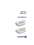
1
9070
User Manual
Rev. 002
Compuprint Products Information
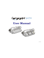
Thanks for choosing the Compuprint 9070 printer.
Your printer is a reliable working equipment that will be very useful in your daily job.
Our printers have been designed to be compact and respectful of the work environment. They offer
a wide range of features and multiple functions that confirm the high technological level reached
by the printers with Compuprint brand.
To maintain these printing performances unchanged in the long run, Sferal wwt has
developed specific Compuprint branded consumables for each printer type (for example: ribbon
cartridges for dot matrix printers, toner and OPC cartridges for laser printers, bubble ink jet
cartridges for inkjet printers) that assure an excellent operation with high printing quality level
reliability.
Sferal wwt recommends to use only its original Compuprint branded consumables with
original packaging (identified by its holographic label). In this way, a proper use of the printer at
quality level stated in the product characteristics can be assured. All typical usage problems
related to not certified consumables may be avoided, such as an overall quality print level
degradation and, often, the reduction of the product life due to the fact that the proper working
conditions for the print heads, OPC cartridge and other printer parts are not assured.
Moreover, Sferal does not only certify its consumables in terms of working conditions but also
carefully controls their compliance with the international standard rules concerning:
• no cancerous materials;
• no flammability of the plastic materials;
• other standards
Sferal advises the customers not to use products for which the compliance to this safety rules are
not warranted. Finally seek your dealer or contact a Sferal office and be sure that are provided you
the original Compuprint branded consumables.
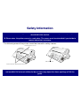
Safety Information
A. Never remove any printer cover except to install a printer accessory and as expressly
described in this manual.
B. Please store the printer covers in a safe place. The covers must be reinstalled if you decide to
remove any printer accessory.
The following areas of the printer should be covered for safety reasons:
R e ar P ull Tracto r C o ve r
A S F A re a C over
R e ar P ull Tracto r A ttach m e nt Are a C ove rs
The above openings must always be protected with their cover when the corresponding option is
not installed. Do not touch inside and do not insert any object into these openings or into the
gears.
FFC Notes
This equipment has been tested and found to comply with the limits for a Class B digital device, pursuant to Part 15 of the FCC Rules.
These limits are designed to provide reasonable protection against harmful interference when the equipment is operated in a
commercial environment. This equipment generates, uses and can radiate radio frequency energy and, if not installed and used in
accordance with the instruction manual, may cause harmful interference to radio communications. However, there is no guarantee that
interference will not occur in a particular installation. If this equipment does cause harmful interference to radio or television reception,
which can be determined by turning the equipment off and on, the user is encouraged to try to correct the interference by one or more of
the following measures:
•
•
•
•
Reorient or relocate the receiving antenna.
Increase the separation between the equipment and the receiver.
Connect the equipment into an outlet on a circuit different from that to which the receiver is connected
Consult the dealer or an experienced radio/TV technician for help.
A shielded Centronics IEEE1284 compliant bi-directional parallel cable, maximum length 3 meters (10 feet), and a shielded RS-232
serial cable, maximum length 15 meters (50 feet), are necessary for this device to meet the requirements of a Class B digital device
pursuant to part 15 of the FCC rules.
The above specified cables are readily available as Personal Computer or Peripheral accessories from multiple retail outlets.
Please consult your dealer for details concerning such cables and also for information about FCC rules for digital devices.
Changes or modifications to the device covered by this manual, which are not expressly approved by the party responsible for
compliance, could void the user’s authority under the FCC rules to operate the equipment.
Canadian D.O.C. Radio Interference Regulation
This digital apparatus complies with the Canadian ICES-003 Class B limits for radio frequency emissions.
Cet appareil numérique est conforme aux limites de Classe B de la norme NMB-003 du Canada.
EEC Regulations
This equipment conforms to the EEC Directive 89/392 (the sound pressure, measured according to ISO 7779, does not exceed 70
dBA).
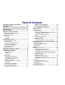
Table of Contents
Compuprint Products Information ...................... ii
Safety Information................................................. iii
FCC Notes .............................................................. iv
Canadian D.O.C. Radio Interference Regulation iv
EEC Regulations ................................................... iv
Table of Contents................................................... v
Getting to Know Your Printer ............................... 1
Printer Features (PRT9070 Model)..................................... 1
Printer Features (PRT9071 Model)..................................... 2
Unpacking Your Printer........................................................ 3
Printer Parts .......................................................................... 4
Front View ........................................................................ 4
Rear View......................................................................... 6
Setting Up Your Printer ......................................... 7
Choosing a Suitable Location.............................................. 7
Printer Assembly .................................................................. 8
Removal of the Shipment Locks ..................................... 8
Ribbon Cartridge Installation ........................................... 9
Host Computer Connection ............................................... 14
Software Driver Selection................................................... 15
Power Connection .............................................................. 16
Selecting the Display Language......................... 18
Configuring the Printer........................................ 19
Operator Panel Presentation ............................................. 19
Display Messages.......................................................... 20
Indicators ........................................................................ 25
Function Keys ................................................................ 26
Printer Setups ..................................................................... 31
Entering the Printer Setups ........................................... 31
Moving within the Printer Setups................................... 31
Leaving the Printer Setups ............................................ 32
Power-On Configuration..................................................... 33
Entering the Power-On Configuration........................... 33
Program Setup ................................................................... 76
Entering the Program Setup.......................................... 76
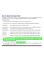
How to Select the Paper Path..........................................103
How to Use the Tear-Off Function...................................104
Selection of the Paper Size .........................................104
Adjusting the Tear-Off Position ................................... 105
Selection of the Tear-Off Mode................................... 106
How to Lock/Unlock the Printer Setups .......................... 107
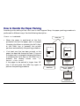
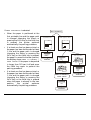
How to Handle the Paper Parking................................... 108
Paper Handling................................................... 113
Paper Paths...................................................................... 113
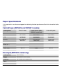
Paper Specifications ........................................................ 114
Fanfold Paper (PRT9070 and PRT9071 models)...... 114
Envelopes (PRT9070 model only).............................. 114
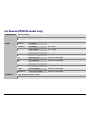
Cut Sheets (PRT9070 model only)............................. 115
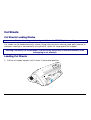
Cut Sheets........................................................................ 116
Cut Sheets Loading Modes......................................... 116
Loading Cut Sheets ..................................................... 116
Fanfold Paper Loading..................................................... 119
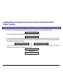
Loading Paper Using the Front1 Push Tractor .......... 119
Printer Maintenance and Troubleshooting...... 127
Cleaning the Printer.......................................................... 127
Replacing the Ribbon Cartridge ...................................... 128
Printing the Self Test........................................................ 130
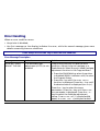
Error Handling .................................................................. 131
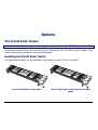
Options ............................................................... 134
The Front2 Push Tractor.................................................. 134
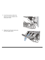
Installing the Front2 Push Tractor............................... 134
Removing the Front2 Push Tractor............................. 137
Loading Paper Using Front2 Push Tractor (option)... 138
Loading Paper Using F1 Push & F2 Push Tractor
(Option) is Installed ...................................................... 144
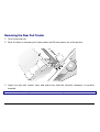
The Rear Pull Tractor....................................................... 146
Installing the Rear Pull Tractor.................................... 146
Removing the Rear Pull Tractor.................................. 149
Loading Paper Using F1 Push & Rear Pull Tractor .. 151
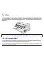
The Cutter......................................................................... 154
The LAN Interface Board ................................................. 154
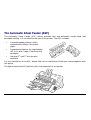
The Automatic Sheet Feeder (ASF)................................ 155
The Color Kit..................................................................... 156
The Printer Pedestals....................................................... 157
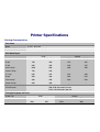
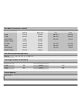
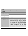
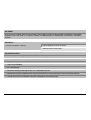
Printer Specifications ........................................ 158
Getting to Know Your Printer
Printer Features (PRT9070 Model)
• 24 Needle Print Head
• 136 columns @10 cpi
• Draft printing at 700 cps, LQ printing at 133 cps
• IBM Proprinter XL24/XL24 AGM, Personal Printer 2391+ and EPSON LQ Series emulations
• Base paper handling configuration: Front1 push path (fanfold) + Manual paper path (cut sheets)
• Multiple copies (1 original and 7 copies)
• Automatic paper path selection
• Automatic Sheet Feeder option which handles cut sheets, multicopy and envelopes, accepts up to
two additional paper bins and includes paper stacker
• Easy operability via operator panel setup and S/W commands
• Usage of all specific features by means of the Specific Software Driver which is applicable to the
most popular S/W Packages
• Plug & Play capability for Windows 95/98/2000/XP/NT4.0/Millennium ®
• Bi-directional IEEE 1284 parallel interface and standard serial RS-232/C and RS-422/A interface
• Ethernet 10/100 Base-T interface option that coexists with the parallel interface
• Optional 6 pin 1° Front Push Tractor
• Optional 4 pin Rear Pull Tractor
• Color Kit option
• Paper Cutter option
• Two optional printer pedestals
1
Printer Features (PRT9071 Model)
• 24 Needle Print Head
• 136 columns @10 cpi
• Draft printing at 700 cps, LQ printing at 133 cps
• IBM Proprinter XL24/XL24 AGM, Personal Printer 2391+ and EPSON LQ Series emulations
• Base paper handling configuration: : Front1 push path (1st fanfold)
• Multiple copies (1 original and 7 copies)
• Automatic paper path selection
• Automatic Sheet Feeder option which handles cut sheets, multicopy and envelopes, accepts up to
two additional paper bins and includes paper stacker
• Easy operability via operator panel setup and S/W commands
• Usage of all specific features by means of the Specific Software Driver which is applicable to the
most popular S/W Packages
• Plug & Play capability for Windows 95/98/2000/XP/NT4.0/Millennium ®
• Bi-directional IEEE 1284 parallel interface and standard serial RS-232/C and RS-422/A interface
• Ethernet 10/100 Base-T interface option that coexists with the parallel interface
• Optional 6 pin 1° Front Push Tractor
• Optional 4 pin 2° Front Push Tractor (2nd fanfold)
• Optional 6 pin 2° Front Push Tractor (2nd fanfold)
• Optional 4 pin Rear Pull Tractor
• Color Kit option
• Paper Cutter option
• Two optional printer pedestals
2
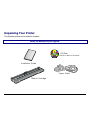
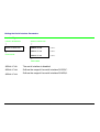
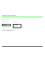
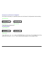
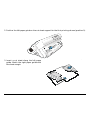
Unpacking Your Printer
The following items are included in the box:
Notify any damage to your supplier.
C D -R o m
( w ith U se r M a nu al in clud e d )
In sta lla tio n G u id e
P o w e r C a b le
R ibb o n C a rtrid g e
3
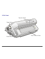
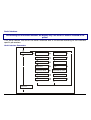
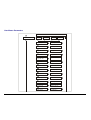
Printer Parts
Front View
PRT9070 Model
O pe ra to r P a ne l
P a pe r K no b
C u t S h e et S up po rt
P u sh Tracto rs C over
P o w er S w itch
P a pe r G u id es
4
PRT9071 Model
O pe ra tor Pane l
Pa per Kn ob
Pu sh Tractors C over
Po w er Sw itch
5
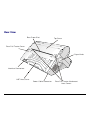
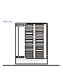
Rear View
R e ar P ap er S lo t
Top C o ve r
R e ar P ull Tracto r C o ve r
P a pe r K n o b
In te rfa ce C o nn ecto rs
A S F A re a C ove r
P o w er C ab le C o nn ecto r
6
R e ar P ull Tracto r A ttach m e nt
A re a C ove rs
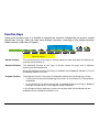
Setting Up Your Printer
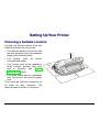
Choosing a Suitable Location
Consider the following points when you
choose the location for your printer:
• The distance between the printer and
the host computer must not exceed the
length of the interface cable;
• The location must
horizontal and stable;
be
80 cm
3 1.5 in.
sturdy,
• Your printer must not be exposed to
direct sunlight, extreme heat, cold,
dust or humidity (see "Printer
Specifications" later);
1
39 00
.4 cm
in
m
20 c
in
7 .9
m
20 c
7 . 9 in
7
cm
0 in
1 0 .4
39
• The power outlet must be compatible
with the plug of the printer's power
cord.
There must be sufficient clearances on
all sides for easy operation. The
required space is shown in the figure:
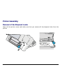
Printer Assembly
Removal of the Shipment Locks
Open all the printer covers and make sure that you remove all the shipment locks from the
printer.
8
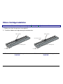
Ribbon Cartridge Installation
Make sure that you are using only Compuprint original consumables.
1. Make sure that the printer is turned off.
2. Find the ribbon cartridge among the accessories
R ib b on G uide
R ib b on G uide
C o lo r S h ifter H olde r
R ib b on W ind in g K no b
R ib b on W ind in g K no b
C a rtridg e P in s
C a rtridg e P in
To be used when the color kit option is not
installed
To be used when the color kit option is
installed
9
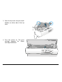
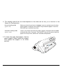
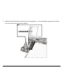
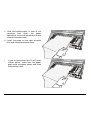
3. Open the top cover using the small
handles on either side of the top
cover.
4. Turn the printer on. The print
carriage prepares for ribbon
cartridge installation.
10
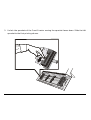
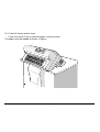
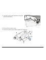
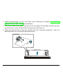
5. Before installing the ribbon cartridge
turn the ribbon-winding knob in the
arrow direction (located on the cartridge)
to take up slack in the ribbon.
C a rtridge Pins
R ibbon W inding Knob
To avoid damage to the ribbon, do not turn the winding knob in the wrong direction.
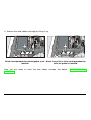
6. Align the right and left cartridge pins with the printer locking points.
Black cartridge when the color kit option is not
installed
11
Black “Long Life” or Color cartridge when
the color kit option is installed
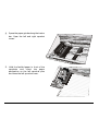
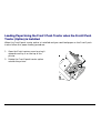
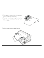
7. Slide and insert the ribbon guide between the print head and the ribbon guide mask holding it
perpendicular to the print head.
Make sure that the ribbon is inserted correctly between the print head and the print head mask.
12
2.
8. If the color kit option is installed on
your printer, insert the shifter holder
onto the color shifter as shown in
this figure.
R ib b on G uide
Sh ifter H olde r
C o lo r Sh ifter
12
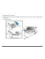
9. Turn the ribbon-winding knob in the arrow direction (located on the cartridge) to take up
slack in the ribbon.
10. Push the cartridge down gently until it clips into place at locking points.
Black cartridge when the color kit option is not
installed
Black “Long Life” or Color cartridge when
the color kit option is installed
11. Turn the ribbon-winding knob again in the direction of the arrow to take up slack in the ribbon.
12. To ensure that the ribbon guide runs freely along the ribbon, manually move the print carriage
horizontally.
If the used ribbon cartridge needs to be replaced, see "Replacing The Ribbon Cartridge", later in this
manual.
13
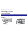
Host Computer Connection
This printer can be connected to your host computer via two available interfaces. The interface
connectors are located on the rear of the printer.
• A bidirectional IEEE1284 parallel interface
• A RS-232C/422A serial interface
Before connecting the interface cable, make sure that the printer and the host computer are
turned OFF .
Insert the parallel interface cable into the parallel connector and fasten it by means of the clips.
Insert the serial interface cable into the serial connector and fasten it by means of the two screws (use
the screwdriver).
Parallel Interface
Serial Interface
14
Software Driver Selection
At this point it is necessary to configure your printer for your application package. The installation
procedures depend upon the host environment.
Follow the instructions in the readme file you find on the CD-ROM.
In a WINDOWS 95/98/2000/XP/NT4.0/Millennium® environment the printer supports the Plug &
Play feature.
The printer drivers of all Compuprint printers can be found at the Internet Address
http://www.compuprint.net/
15
Power Connection
The power outlet must be compatible with the plug of the printer’s power cable.
Always use a grounded outlet.
1. Make sure the power outlet is near the printer location and easily accessible.
2. Make sure that the power switch is in 0
position (OFF).
16
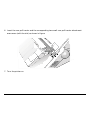
3. Insert the power cable plug into the printer connector and the other power cable end into a
convenient outlet (the figure shows the European version).
1
2
4. If you need to turn the printer on, press the
power switch in the I position (ON).
17
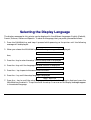
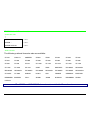
Selecting the Display Language
The display messages for this printer can be displayed in five different languages: English (Default),
French, German, Italian and Spanish. To select the language, that you prefer, proceed as follows:
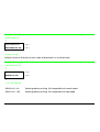
1. Press the PROGRAM key and keep it pressed while powering on the printer until the following
message will be displayed:
RELEASE KEY
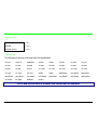
2. When you release the PROGRAM key, the following messages will be displayed:
9070
then,
PRINT OUT? NO
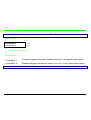
3. Press the ↓ key to enter the setup. The first setup item is displayed:
EMUL. OPTIONS
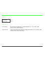
4. Press the ↓ key until the language first level function is displayed:
FUNCTIONS
5. Press the → key to pass to the second level functions:
BUZZER YES
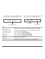
6. Press the ↓ key until the setup language is displayed:
MENU ENGLISH
7. Press the → key to scroll the setup languages. When the desired language is displayed, press the
PROGRAM key to select it. The printer exits the setup. From now on the display messages appear
in the selected language.
18
Configuring the Printer
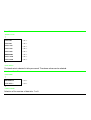
Operator Panel Presentation
The operator panel enables you to perform many of the printer functions including paper path
selections, font selection and the printer setup.
)URQW )URQW $6)
352*5$0
3$7+
7($5
3$5.
3,7&+
$/7(51$7(
/2$'))
/)
0,&52 )(('
The operator panel consists of:
• A 16 character display (Liquid Crystal Display)
• Six led indicators
• Nine function keys
19
)217
0$&52
21 /,1(
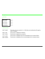
Display Messages
The printer display is used to indicate the printer status or to request an user intervention.
When the printer is in Ready state, the display gives the following information:
•
when paper is already loaded and the •
printer is off line (ON LINE indicator unlit):
OFF LINE
when paper is already loaded and the
printer is on line (ON LINE indicator lit):
ON LINE
M1
M1
P rin te r S ta tu s
P rin ter S ta tu s
C u rre n t M a cro
C u rre n t M a cro
where:
OFF LINE
ON LINE
Indicates the printer status.
M1, M2, M3, M4
Indicate which of the four User Macros is currently used.
20
•
when there is no paper loaded and the •
printer is off line (ON LINE indicator unlit):
when there is no paper loaded and the
printer is on line (ON LINE indicator lit):
ON LINE
Load Front1
M1
P rin te r S ta tu s
C u rre n t M a cro
C u rre n t P a p er P a th
where:
LOAD FRONT1
LOAD FRONT2
LOAD PUSH-PULL
LOAD FR1 PUSH&MF
LOAD MANUAL FORM
LOAD PSH-PLL&MF
LOAD ASF1
LOAD ASF2
LOAD ASF3
Indicates that the currently selected paper path is out of paper.
The messages are displayed only for the available paper paths,
according to the installed devices.
LOAD FRONT2 (only PRT9071 model)
LOAD FR1 PUSH&MF (only PRT9070 model)
LOAD MANUAL FORM (only PRT9070 model)
LOAD PSH-PLL&MF (only PRT9070 model)
OFF LINE
ON LINE
Indicates the printer status.
M1, M2, M3, M4
Indicate which of the four User Macros is currently used.
21
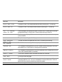
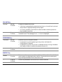
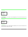
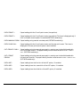
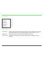
The following messages appear to indicate other printer conditions or user intervention requests.
The list is in alphabetical order.
Message
Description
ALTERNATE
This message appears to indicate that the Alternate functions of the operator
panel keys have been selected pressing the ALTERNATE key.
BUSY
This message appears to indicate that the printer is printing. It is busy.
M1
COVER OPEN
CLOSE COVER
When the printer cover is not closed correctly, the buzzer sounds and the
display shows alternately these two messages. Close the printer cover.
EJECTING
The printer is ejecting the paper out of the printer.
INITIALIZING LAN
This message is displayed when the LAN is reset (only if the LAN interface
board is installed).
LOAD
LOAD
LOAD
LOAD
LOAD
LOAD
LOAD
LOAD
LOAD
FRONT1
FRONT2
PUSH-PULL
FR1 PUSH&MF
MANUAL FORM
PSH-PLL&MF
ASF1
ASF2
ASF3
These messages are displayed when the corresponding paper path is out of paper.
The printer displays only the messages related to the installed devices.
FR1 PUSH&MF = Front1 push and manual paper path.
PSH-PLL&MF = Push-Pull and manual paper path.
LOCKED MENU
When the access to the Printer Setups has been locked at the power on, the
printer displays this message.
MACRO CHANGING
The macro has been changed and the printer is updating the settings.
22
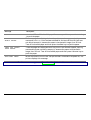
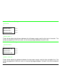
Message
Description
MICRO FEED DOWN
The paper is fed in microsteps downwards when pressing the ↓ arrow key .
MICRO FEED UP
The paper is fed in microsteps forwards when pressing the ↑ arrow key.
OPT. I/F CHANGED
PRESS ON LINE
These messages are displayed at power on when the I/F board option has been
changed previously in the printer. Press the ON LINE key to confirm.
OPER. INTERRUPTED
This message is displayed if the ALTERNATE key has been pressed to interrupt a
park procedure.
PARKING
The printer is parking the fanfold paper.
PATH CHANGING
The path has been changed and the printer is updating the settings.
PRESS A KEY
NVM CHANGED
The NVM has been changed. Press any key to set the printer.
RELEASE KEY
This message is displayed when you can release the PROGRAM key in the Selftest selection or in the Power-on Configuration procedure.
REMOTE CONTROL
This message is displayed when the printer operates from remote control (only
if the LAN interface board is installed).
RESET & BREAK
The printer received a reset and break command via interface.
SELF TEST
Printing the self-test page.
TEAR IF NECESS.
EJECT PAPER
These messages are displayed when the printer receives a paper parking
command and the TEAR NO item is selected for the tear-off function. Tear off
the fanfold then press the PARK key to eject the paper.
These messages are displayed when the printer receives a paper parking
TEAR IF NECESS.
23
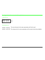
Message
Description
PARK PAPER
TEAR OFF PAPER
EJECT PAPER
command. Tear off the fanfold paper if necessary and then press the PARK key
to park the paper.
These messages are displayed when the printer receives a paper ejecting
command (TEAR NO item has been selected for the tear-off function) but was
not able to execute it, because the paper to be ejected is longer than 18 inch.
Tear off the fanfold paper and then press the PARK key to eject the paper.
TEAR OFF PAPER
PARK PAPER
These messages are displayed when the printer has received a paper parking
command but was not able to execute it, because the paper to be parked is
longer than 18 inch. Tear off the fanfold paper and then press the PARK key to
park the paper.
UNLOCKED MENU
When the access to the Printer Setups has been unlocked at the power on, the
printer displays this message.
For the error messages see "Error Handling” later in this manual.
24
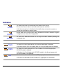
Indicators
Lit when the printer can receive and print data (printer online).
21/,1(
Blinks when there is data in the buffer and the printer is offline.
Unlit when the printer is disabled and the buffer does not contain any data, or
during the initialization, setup or tests.
352*5$0
Blinks when one of the printer setup procedures has been selected: Program
Configuration or Power-On Configuration.
Lit when the alternate function of the keys has been enabled pressing the
$/7(51$7(
7439
7439
ALTERNATE key.
Lit when the Front1 paper path or the Push-pull paper path is selected.
Unlit when neither the Front1 paper path nor Push-pull paper path are selected.
Lit when the Front2 paper path (PRT9071 model) or the Manual paper path
(PRT9070 model) is selected.
Unlit when the Front2 paper path (PRT9071 model) or the Manual paper path
(PRT9070 model) is not selected.
$
Lit when the Automatic Sheet Feeder (ASF) paper path is selected.
Unlit when the Automatic Sheet Feeder (ASF) paper path is not selected.
25
Function Keys
Pressing the function keys it is possible to activate the functions indicated by the word or symbol
signed near the key. Each key may have different functions, according to the selected function
modes: Normal, Alternate or Program.
P rogram F unction
352*5$0
N orm a l function
3$7+
7($5
3$5.
3,7&+
$/7(51$7(
/2$'))
/)
)217
21 /,1(
0$&52
0,&52 )(('
A lternate function
Normal Function
The normal function of the keys is written above the keys and does not require any
previous action to select it.
Alternate Function
The alternate function of the keys is written below the keys and is selected
pressing the ALTERNATE key.
When the alternate function of the keys is selected, the ALTERNATE indicator is lit and
the display shows ALTERNATE.
Program Function
The program function of the keys is selected pressing the PROGRAM key, where:
• If you press the key while powering the printer on, the Power-On Configuration
is selected.
• If you press the key when the printer is enabled without printing or disabled
(ON LINE indicator unlit), the Program Setup is selected.
In the Program Setup mode only the four arrow keys and the PROGRAM key are
enabled and the PROGRAM indicator is lit.
26
ON LINE Key
ON LINE
Normal
Function
Enables or disables the printer.
• If this key is pressed while powering the printer on, the self test is printed;
the printout is stopped pressing this key again.
• In an error condition, once the error cause has been removed, press this
key to enable the printer
Program
Function
Pressing this key, the input buffer is cleared an a break (250 msec.) on a serial
interface is sent. The message RESET & BREAK is displayed.
PROGRAM Key
PROGRAM
Normal
Function
Enables the printer setups as follows:
• Pressing this key while powering on the printer, the Power-On
Configuration is selected.
• Pressing this key when the printer is enabled without printing or disabled
the Program Setup is enabled (PROGRAM indicator lit).
Program
Function
Exits the printer setups.
MACRO
Normal
Function
Selects one of the user macros (Macro 1, Macro 2, Macro 3 or Macro 4). If you
want to select the displayed macro, wait for 2 seconds without pressing any
key and the parameters of this macro will be set .
→
Program
Function
Scrolls the parameters of the functions or macros forwards.
MACRO Key
27
FONT Key
FONT
Normal
Function
Selects the font to be used with the currently selected pitch. The selected font
is valid until the printer is turned off or a new font is selected using this key.
←
Program
Function
Scrolls the parameters of the functions or macros backwards.
LF
Normal
Function
Performs a line feed according to the current line spacing settings.
MICRO FEED
Alternate
Function
Moves the paper forward in microsteps. Keeping the key pressed the paper is
moved continuously at increasing speed.
↑
Program
Function
Scrolls the setup and macro functions backwards.
LF Key
LOAD/FF Key
LOAD/FF
Normal
Function
Executes a Form Feed (FF): when paper is loaded into the printer, it advances
to the following page; if no paper is loaded, it is positioned for printing.
MICRO FEED
Alternate
Function
Moves the paper backward in microsteps. Keeping the key pressed the paper
is moved continuously at increasing speed.
↓
Program
Function
Scrolls the setup and macro functions forwards.
28
ALTERNATE Key
ALTERNATE
Normal
Function
Enables the alternative key functions.
If the printer is receiving print data, press the ON LINE key before pressing the
ALTERNATE key.
If no printing data are in the print buffer, pressing the ALTERNATE key, the printer
goes offline.
The display then shows ALTERNATE to indicate that the Alternate Function
of the keys is enabled (ALTERNATE indicator lit).
May be used to abort paper parking procedure. See also “ How to Handle the
Paper Parking ”, later in this manual.
When the printer is in Program Setup Mode, this key is disabled.
Alternate Disables the alternative key functions.
Function
TEAR/PITCH Key
TEAR
Normal
Function
Moves the paper to the tear-off position (TEAR NORMAL function must be selected
in the Program Setup).
PITCH
Alternate
Function
Selects the pitch to be used with the currently selected font. The selected pitch is
valid until the printer is turned off.
29
PATH/PARK Key
PATH
Normal
Function
Selects one of the paper paths in offline status. The parameters of the displayed
path are set after 2 seconds without pressing any key.
PARK
Alternate
Function
Parks the paper in the currently selected paper path.
Key Combinations
ONLINE + MACRO + ALTERNATE Normal
Function
Lock or unlock the access to the printer setups. See later
“How to Lock/Unlock the Printer Setups” section.
30
Printer Setups
The main printer setup parameters can be selected via the operator panel. The setup parameters are
divided into two printer setups, the Power-On Configuration, that allows a complete configuration at
installation time according to the hardware and the emulation types, and the Program Setup, that
allows you to set the functions that are the most useful in your daily job. These settings can be
selected when the printer is online without printing or offline (ON LINE indicator unlit) and stored in
the NVM.
Entering the Printer Setups
•
Press the PROGRAM key and keep it pressed at the printer power on until the RELEASE KEY
message is displayed to select the Power-On Configuration.
•
Press the PROGRAM key when the printer is online without printing or offline (ON LINE
indicator unlit) to select the Program Setup.
Moving within the Printer Setups
The arrow keys ↑, ↓, ← , → are used to move within the different functions inside the Printer Setups.
See the following description of the setup items.
31
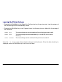
Leaving the Printer Setups
• Pressing the PROGRAM in the Power-On Configuration key the printer exits from the setup and
the new settings will be automatically saved.
• Pressing the PROGRAM key in the Program Setup, the following choice is offered for the storage of
the values set:
STORE? QUIT
The new settings are not activated and the old settings remain valid.
STORE? SAVE
The new settings are stored permanently in the NVM (Non Volatile
Memory).
STORE? CURRENT
The new settings remain valid until the printer is turned off.
Press the → or ← keys to scan these selections forward and backwards. When the desired setting is
displayed, press the PROGRAM key to exit from the Setup.
32
Power-On Configuration
The default values of the various functions are indicated in bold.
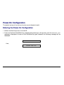
Entering the Power-On Configuration
1. Make sure that the printer is turned off.
2. Press and hold the PROGRAM key pressed while powering on the printer until the RELEASE KEY
message is displayed. As soon as the PROGRAM key gets released, the following message will be
displayed:
9070
then,
PRINT OUT? NO
33
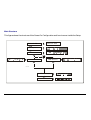
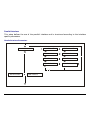
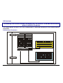
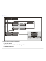
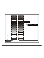
Main Structure
This figure shows the structure of the Power-On Configuration and how to move inside the Setup.
P rint out? Y E S
P rint out? N O
E m ul. O ptions
P arall Interface
S erial Interface
LA N Interface
F unctions
B ack to M F G ? N O
34
The setup item Functions groups the following printer functions:
•
•
•
•
•
•
•
•
•
•
•
•
•
•
•
Buzzer setting,
Paper loading sequence,
Paper overlay (only PRT9070 model),
Quick cut sheet loading (only PRT9070 model),
Ribbon type,
Bar code density,
Text printing direction,
Graphics printing direction,
Bar code printing direction,
Graphics printing speed,
Paper path at power on,
Language of the display messages,
Paper tractor jam sensors (if the optional 6 pin Front 1/Front2 Push tractors are installed),
Tear-off position adjustment
Cut position adjustment (if the optional cutter is installed)
Printout of the Printer Settings
PRINT OUT? NO
→ or ← PRINT OUT? YES
↓
EMUL. OPTIONS
PRINT OUT? NO
The Setup is not printed.
PRINT OUT? YES
The printer setup is printed showing the currently selected values. The
printout starts as soon as you select this value.
35
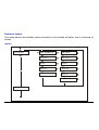
Emulation Options
This setup defines the available options according to the selected emulation and is structured as
follows:
Options
E m ul. O ptions
E m ul E PS O N LQ
E m ul IB M ...
C har. S et ...
C har. S et ...
N ation ...
N ation ...
A uto CR ...
A uto CR …
A uto LF …
A uto LF ...
20 C P I IBM ...
P arall. In terface
36
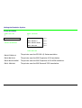
Setting the Emulation Options
Printer Emulation
PRINT OUT? NO
EMUL. OPTIONS
↑
↑
EMUL. EPSON LQ
→ or ←
↓
EMUL. IBM XL24
→ or ←
PARALL INTERFACE
EMUL. IBM XL24AGM
→ or ←
EMUL. IBM 2391
→ or ←
EMUL. OPTIONS
→
↓
CHAR. SET CS2
EMUL EPSON LQ
The printer uses the EPSON LQ Series emulation.
EMUL IBM XL24
The printer uses the IBM Proprinter XL24 emulation.
EMUL IBM XL24AGM
The printer uses the IBM Proprinter XL24 AGM emulation.
EMUL. IBM 2391
The printer uses the IBM Personal 2391+ emulation.
37
EPSON Character Sets
EMUL. EPSON LQ
↑
CHAR. SET CS1
→ or ←
CHAR. SET CS2
→ or ←
CHAR. SET ITALIC
→ or ←
↓
NATION CP437
These items select the character set to be used in EPSON emulation.
IBM Character sets
EMUL. IBM xxx
↑
CHAR. SET CS1
→ or ←
CHAR. SET CS2
→ or ←
↓
NATION CP437
These items select the character set to be used in IBM Proprinter emulation.
38
EPSON National Character sets
CHAR. SET CS2
↑
NATION CP437
→ or ←
NATION …
→ or ←
NATION LATIN A1
→ or ←
↓
AUTO CR YES
The following national character sets are available:
CP 437
CP437 G
96GREEK
CP850
CP851
CP 852
CP 853
CP 855
CP 857
CP 858
CP 860
CP 862
CP 863
CP 864
CP 865
CP 866
CP 867
CP 876
CP 877
CP 1250
CP 1251
CP 1252
CP 1253
CP 1254
CP 1255
CP 1256
CP 1257
GOST
TASS
MAZOWIA
ISO 8859/1
ISO 8859/2
ISO 8859/3
ISO 8859/4
ISO 8859/5
ISO 8859/6
ISO 8859/7
ISO 8859/8
ISO 8859/9
ISO 8859/15
CP 437SL
CP 1098
UKRAIN
KOI8-U
USA
FRANCE
GERMANY
ENGLAND
DENMARK1
SWEDEN
ITALY
SPAIN1
JAPAN
NORWAY
DENMARK2
SPAIN2
LATIN A1
The CP 858 and ISO 8859/15 character sets contain the Euro character.
39
IBM National Character Sets
CHAR. SET CS2
↑
NATION CP437
→ or ←
NATION …
→ or ←
NATION KOI8-U
→ or ←
↓
AUTO CR NO
The following national character sets can be selected:
CP 437
CP437 G
96GREEK
CP850
CP851
CP 852
CP 853
CP 855
CP 857
CP 858
CP 860
CP 862
CP 863
CP 864
CP 865
CP 866
CP 867
CP 876
CP 877
CP 1250
CP 1251
CP 1252
CP 1253
CP 1254
CP 1255
CP 1256
CP 1257
GOST
TASS
MAZOWIA
ISO 8859/1
ISO 8859/2
ISO 8859/3
ISO 8859/4
ISO 8859/5
ISO 8859/6
ISO 8859/7
ISO 8859/8
ISO 8859/9
ISO 8859/15
CP 437SL
CP 1098
UKRAIN
KOI8-U
The CP 858 and ISO 8859/15 character sets contain the Euro character.
40
CR Code Behavior
NATION xxx
↑
AUTO CR NO
→ or ←
AUTO CR YES
→ or ←
↓
AUTO LF NO
AUTO CR NO
No automatic carriage return is performed after a LF, VT or ESCJ code.
Default value in IBM emulation.
AUTO CR YES
The printer performs an automatic carriage return after a LF, VT or ESCJ code.
Default value in EPSON emulation.
41
LF Code Behavior
AUTO CR xx
↑
AUTO LF NO
→ or ←
AUTO LF YES
→ or ←
AUTO LF HOST
→ or ←
↓
20 CPI IBM NO
or
EMUL. OPTIONS
AUTO LF NO
No Automatic LF after CR.
AUTO LF YES
Automatic LF after CR.
AUTO LF HOST
Only in EPSON emulation. The printer checks the AUTOFEEDXT signal coming
from the host and executes an automatic LF after CR, if the signal is low.
42
IBM Compressed Printing
These items are displayed only if the IBM emulation is selected.
AUTO LF NO
↑
20 CPI IBM NO
→ or ←
20 CPI IBM YES
→ or ←
↓
EMUL. OPTIONS
20 CPI IBM NO
The compressed printing is performed at 17.1 cpi.
20 CPI IBM YES
The compressed printing is performed at 20 cpi.
43
Parallel Interface
This setup defines the use of the parallel interface and is structured according to the interface
specific parameters.
Parallel Interface Parameters
P arall Interface
S erial Interface
RU
1284 B id ir. I/F
C X . P arallel I/F
S elect-In H ost
S elect-In O n
D ata Bits 8
D ata Bits 7
Input B uffer 2 K
Input B uffer …
LA N Interface
44
Setting the Parallel Interface Parameters
Interface Type
EMUL. OPTIONS
PARALL INTERFACE
↑
↑
1284 BIDIR. I/F
→ or ←
↓
CX. PARALLEL I/F
→ or ←
SERIAL INTERFACE
↓
or
SELECT-IN HOST
PARALL INTERFACE
→
LAN INTERFACE
1284 BIDIR. I/F
Bidirectional IEEE 1284 parallel interface.
CX. PARALLEL I/F
Centronics type parallel interface (monodirectional).
Setting the Select-In Signal
1284 BIDIR . I/F
↑
SELECT-IN HOST
→ or ←
SELECT-IN ON
→ or ←
↓
DATA BITS 8
SELECT-IN HOST
The printer checks the SELECT-IN signal coming from the host.
SELECT-IN ON
The SELECT-IN signal of the parallel interface is ignored and treated always
as ON.
45
Number of Data Bits
SELECT-IN HOST
↑
DATA BITS 8
→ or ←
DATA BITS 7
→ or ←
↓
INP. BUFFER 2K
Selection of the number of data bits: 7 or 8
Input Buffer Size
DATA BITS 8
↑
INP. BUFFER 256
→ or ←
INP. BUFFER 2K
→ or ←
INP. BUFFER 12K
→ or ←
INP. BUFFER 32K
→ or ←
INP. BUFFER 64K
→ or ←
INP. BUFFER 128K
→ or ←
↓
PARALL. INTERFACE
Selects the input buffer size.
46
Serial Interface
The following Serial interface functions will display only if the Serial I/F board is installed in the
printer.
This setup defines the use of the serial interface and is structured according to the interface
specific parameters.
Serial Interface Parameters
Serial Interface
Serial I/F N o
Serial I/F ...
Baud 9600
Baud ...
D ata Bits 8
D ata Bits 7
Parity N on e
Parity ...
H and sh ake D TR
H and sh ake X on /X of
C onn ection L ocal
C onn ect. R em o te
Input B uffer 2 K
Input B uffer ...
Fu nctions
47
Setting the Serial Interface Parameters
Interface Type
PARALL INTERFACE
SERIAL INTERFACE
↑
↑
SERIAL I/F NO
→ or ←
↓
SERIAL I/F 232
→ or ←
FUNCTIONS
SERIAL I/F 422
→ or ←
SERIAL INTERFACE
→
↓
BAUD 9600
SERIAL I/F NO
The serial interface is disabled.
SERIAL I/F 232
Defines the usage of the serial interface RS-232/C.
SERIAL I/F 422
Defines the usage of the serial interface RS-422/A.
48
Baud Rate
SERIAL I/F NO
↑
BAUD 300
→ or ←
BAUD 600
→ or ←
BAUD 1200
→ or ←
BAUD 2400
→ or ←
BAUD 4800
→ or ←
BAUD 9600
→ or ←
BAUD 19200
→ or ←
BAUD 38400
→ or ←
↓
DATA BITS 8
The baud rate is selected in bits per second. The above values can be selected.
Number of Data Bits
BAUD 9600
↑
DATA BITS 8
→ or ←
DATA BITS 7
→ or ←
↓
PARITY NONE
Selection of the number of data bits: 7 or 8.
49
Parity Check
DATA BITS 8
↑
PARITY NONE
→ or ←
PARITY ODD
→ or ←
PARITY EVEN
→ or ←
PARITY MARK
→ or ←
PARITY SPACE
→ or ←
↓
HANDSHAKE DTR
PARITY NONE
Data does not have a parity bit, i.e. 8 bit data are transferred and the parity
check is disabled.
PARITY ODD
Parity check is enabled for odd parity.
PARITY EVEN
Parity check is enabled for even parity.
PARITY MARK
Parity check is disabled and the transmitted parity bit is always a Mark.
PARITY SPACE
Parity check is disabled and the transmitted parity bit is always a Space.
50
Handshake Protocol
PARITY NONE
↑
HANDSHAKE DTR
→ or ←
HANDSHAKE XONXOF
→ or ←
↓
CONNECTION LOCAL
HANDSHAKE DTR
The Handshake is performed using the DTR Protocol.
HANDSHAKE XONXOF The Handshake is performed using the XON-XOFF Protocol.
Connection Type
HANDSHAKE DTR
↑
CONNECTION LOCAL
→ or ←
CONNECT. REMOTE
→ or ←
↓
INP. BUFFER 2K
Selects the connection type: local or remote.
51
Input Buffer Size
CONNECTION LOCAL
↑
INP. BUFFER256
→ or ←
INP. BUFFER 2K
→ or ←
INP. BUFFER12K
→ or ←
INP. BUFFER32K
→ or ←
INP. BUFFER64K
→ or ←
INP. BUFFER128K
→ or ←
↓
SERIAL INTERFACE
Selects the input buffer size.
52
LAN Interface
The following LAN interface functions will display only if the Ethernet 10/100 Mbit interface board
option is installed in the printer.
This setup defines the use of the LAN interface and is structured according to the interface specific
parameters.
LAN Interface Parameters
L A N Inte rfa ce
IP A ssign F ixed
IP A ssign …
In it IP A d d re ss …
In it IP A d d re ss …
S M T P E na bl. N o
S M T P E na bl.Ye s
N o vell E n. N o
N o vell E n. Ye s
F u nctio n s
53
IP Assignment
PARALL INTERFACE
LAN INTERFACE
↑
↑
IP ASSIGN FIXED
→ or ←
↓
IP ASSIGN DHCP
→ or ←
FUNCTIONS
IP ASSIGN ARP
→ or ←
LAN INTERFACE
→
↓
INIT IP ADDRESS 127.000.000.000
IP ASSIGN FIXED
Assigns the static or fixed IP address.
IP ASSIGN DHCP
Assigns the dynamic IP address (DHCP protocol).
IP ASSIGN ARP
Assigns the user’ s defined IP address (ARP protocol).
Init IP Address
IP ASSIGN FIXED
INIT IP ADDRESS 000.000.000.000
→ or ←
INIT IP ADDRESS …
→ or ←
INIT IP ADDRESS 255.255.255.255
→ or ←
↓
INIT NET MASK 255.255.254.000
These values set the INIT IP address. The IP address is represented by a decimal notation where the
decimal values are divided by points in four fields. Each field ranges between 0 and 255. Use the ←
or → keys to increase or decrease the values in one field and the p or n keys to move to the next field
(p to move to the right and n to move to the left). The default value is 127.000.000.000.
54
Init Net Mask
INIT IP ADDRESS 127. 000.000.000
↑
INIT NET MASK 000.000.000.000
→ or ←
INIT NET MASK …
→ or ←
INIT NET MASK 255.255.255.255
→ or ←
↓
DEF. GATEWAY ID 000.000.000.000
These values set the INIT net mask number. This number is represented by a decimal notation
where the decimal values are divided by points in four fields. Each field ranges between 0 and
255. Use the ← or → keys to increase or decrease the values in one field and the p or nkeys to move
to the next field (p to move to the right and n to move to the left). The default value is
255.255.254.000.
ID Default Gateway
INIT NET MASK 255.255.254.000
↑
DEF. GATEWAY ID 000.000.000.000
→ or ←
DEF. GATEWAY ID …
→ or ←
DEF. GATEWAY ID 255.255.255.255
→ or ←
↓
INIT HOST NAME CPG_xxxxxx
These values set the ID default gateway number. This number is represented by a decimal notation
where the decimal values are divided by points in four fields. Each field ranges between 0 and 255.
Use the ← or → keys to increase or decrease the values in one field and the p or nkeys to move to
the next field (p to move to the right and n to move to the left).
55
Init Host Name
DEF. GATEWAY ID 000.000.000.000
↑
INIT HOST NAME ……………
→ or ←
PROGRAM key
↓
INIT WORKGROUP CPG_GROUP
The host is identified by a name. This function allows to create the name of the init host using a 15character string. Use the ← or → keys to increase or decrease the values in one field and the p or
nkeys to move to the next field (p to move to the right and n to move to the left). Press the
PROGRAM key to save the selected init host name. The default name is CPG_xxxxxx.
Init Workgroup Name
INIT HOST NAME CPG_xxxxxx
↑
INIT WORKGROUP ……………
→ or ←
PROGRAM key
↓
SMTP ENABL. NO
The workgroup is identified by a name. This function allows to create the name of the workgroup
using a 15-character string. Use the ← or → keys to increase or decrease the values in one field and
the p or nkeys to move to the next field (p to move to the right and n to move to the left). Press the
PROGRAM key to save the selected init workgroup name. The default name is CPG_GROUP.
56
Enable/Disable the SMTP Service
INIT WORKGROUP CPG_GROUP
↑
→ or ←
SMTP ENABL. NO
SMTP ENABL. YES
↓
↓
NOVELL EN. NO
MAIL SERV.ADDRES 000.000.000.000
SMTP ENABL. NO
Disables the SMTP (Simple Mail Transfer Protocol) service, that is disables
the reception/transfer/error service of the e-mail.
SMTP ENABL. YES
Enables the SMTP (Simple Mail Transfer Protocol) service, that is enables
the reception/transfer/error service of the e-mail.
Mail Server Address
This item is displayed only if the SMTP ENABL. function is selected in YES.
SMTP ENABL. YES
↑
MAIL SERV.ADDRES 000.000.000.000
→ or ←
MAIL SERV.ADDRES …
→ or ←
MAIL SERV.ADDRES 255.255.255.255
→ or ←
↓
EMAIL ADDRESS 000.000.000.000
These values set the mail server address. This number is represented by a decimal notation where the
decimal values are divided by points in four fields. Each field ranges between 0 and 255. Use the ← or
→ keys to increase or decrease the values in one field and the p or nkeys to move to the next field (p to
move to the right and n to move to the left).
57
E-mail Address
This item is displayed only if the SMTP ENABL. function is selected YES.
MAIL SERV.ADDRES 000.000.000.000
↑
EMAIL ADDRESS xxxxxxxxxxx
→ or ←
↓
SENDER ADDRESS xxxxxxxxxxx
This function allows to write the e-mail address where you can notify the failures. Use the ← or →
keys to increase or decrease the values in one field and the p or nkeys to move to the next field (p to
move to the right and n to move to the left). Press the PROGRAM key to save the e-mail address.
Sender Address
This item is displayed only if the SMTP ENABL. function is selected YES.
EMAIL ADDRESS xxxxxxxxxxx
↑
SENDER ADDRESS xxxxxxxxxxx
→ or ←
↓
SMTP ENABL. YES
This function identifies the address of the sender’s e-mail using a string of characters. Use the ← or
→ keys to increase or decrease the values in one field and the p or nkeys to move to the next field (p
to move to the right and n to move to the left). Press the PROGRAM key to save the sender’s e-mail
address.
58
Enable/Disable the Novell Service
SMTP ENABL. NO
↑
→ or ←
NOVELL EN. NO
NOVELL EN. YES
↓
↓
IP ASSIGN FIXED
NOV. SERVER NAME xxxxxxxxxxx
NOVELL EN. NO
Disables the service to see the printer via NOVELL network.
NOVELL EN. YES
Enables the service to see the printer via NOVELL network.
Print Server Name in Novell Network
This item is displayed only if the NOVELL EN. function is selected YES.
NOVELL EN. YES
↑
NOV. SERVER NAME ………..
→o←
↓
NOV. PRINTER NAME xxxxxxxxxxx
This function allows to create the print server name in Novell network. Use the ← or → keys to
increase or decrease the values in one field and the p or nkeys to move to the next field (p to move
to the right and n to move to the left). Press the PROGRAM key to save the print server name. The
default print server name is NW_COMPUPRINT.
59
Printer Name in Novell Network
This item is displayed only if the NOVELL EN. function is selected YES.
NOV. SERVER NAME xxxxxxxxxxx
↑
NOV. PRINTER NAME ……………
→ or ←
↓
NOV. QUEUE NAME xxxxxxxxxxx
This function allows to create the printer name in Novell network. Use the ← or → keys to increase
or decrease the values in one field and the p or nkeys to move to the next field (p to move to the
right and n to move to the left). Press the PROGRAM key to save the printer name. The default
printer name is PS1.
Queue Name in Novell Network
This item is displayed only if the NOVELL EN. function is selected YES.
NOV. PRINTER NAME xxxxxxxxxxx
↑
NOV. QUEUE NAME …………..
→ or ←
↓
NOV.FRAME TYPE xxxxxxxxxxx
This function allows to create the print queue name in Novell network. Use the ← or → keys to
increase or decrease the values in one field and the p or nkeys to move to the next field (p to move
to the right and n to move to the left). Press the PROGRAM key to save the print queue name. The
default printer name is Q1.
60
Frame Type in Novell Network
This item is displayed only if the NOVELL EN. function is selected YES.
NOV. QUEUE NAME xxxxxxxxxxx
↑
NOV.FRAME TYPE 0
→ or ←
NOV. FRAME TYPE …
→ or ←
NOV. FRAME TYPE 30
→ or ←
↓
NOVELL EN YES
These values select the frame type number in Novell network. This number ranges between 0 and
30. The default frame type number is 0.
61
Functions
This item groups various printer functions, with which you can configure the printer.
PRT9070 Model
Fu nctions
(*)
(**)
B uzzer Yes
B uzzer N o
S eque nce N o ne
S eque nce …
Paper Overly N o
Paper Overly Yes
Qu ick Yes
Qu ick No
R ib bon Black
R ib bon Color
B ar C ode 60
B ar C ode 90
Text D irect Bi
Text D irect Uni
Graph D irect B i
Graph D irect U ni
B arcodes D ir. Uni
B arcodes D ir. B i
Graph H .S N o
Graph H.S Yes
P.On P ath M a cro
P.On P ath Last
M enu E nglish
M enu …
F1 Jam Sens. Y
F1 Jam Sens. N
Tear A djust 0
Tear A djust …
C ut A djust 0
C ut A djust …
T h is item is d ispla y ed on ly if the 6 p in F ro n t1 pu sh trac to r o ption is in stalled .
T h is item is d ispla y ed on ly if the c u tter o ption is insta lled .
62
(*)
(**)
PRT9071 Model
Functions
B uzzer Ye s
B uzzer N o
S eque nce N one
S eque nce …
R ibbon Black
R ibbon C olor
B ar C ode 90
B ar C ode 60
Text D irect Bi
Text D irect U ni
Graph D irect Bi
Graph D irect Uni
B arcodes D ir. U ni
B arcodes D ir. B i
Graph H .S No
Graph H .S Yes
P.On P ath Ma cro
P.On P ath Last
M enu EN GLISH
M enu …
F1 Jam Se ns. Y
F1 Jam Se ns. N
(*)
F2 Jam Se ns. Y
F2 Jam Se ns. N
(**)
Tear A djust 0
Tear A djust ....
C ut A djust 0
C ut A djust …
(*) T h is item is disp layed on ly if the 6 pin F ro n t1 pu sh tracto r optio n is in stalled .
(**) T h is item is disp layed on ly if the 6 pin F ro n t2 pu sh tracto r optio n is in stalled .
(***) T h is item is disp layed on ly if the C u tter op tio n is in stalled .
63
(***)
Setting the Functions Group Items
Enable/Disable the Buzzer
SERIAL INTERFACE
or
LAN INTERFACE
FUNCTIONS
↑
↑
→
BUZZER YES
→ or ←
↓
BUZZER NO
→ or ←
RETURN TO MFG: NO
↓
FUNCTIONS
SEQUENCE NONE
Enable or disables the buzzer.
64
Paper Loading Sequence
BUZZER YES
↑
SEQUENCE NONE
→ or ←
SEQ. F1+F2 PUSH (PRT9071 model)
→ or ←
SEQUENCE ASF 1+2
→ or ←
SEQUENCE ASF 123
→ or ←
↓
PAPER OVERLY NO
PRT9070
or
RIBBON BLACK
PRT9071
These items are displayed only if the accessories to which they refer are installed.
SEQUENCE NONE
The paper is fed only through the path selected by operator panel.
SEQ. F1+F2 PUSH
The paper is fed firstly with the Front1 push tractor and successively
through the Front2 push tractor option (PRT9071 model only).
SEQUENCE ASF 1+2
The paper is fed from the first bin of the ASF option until this bin is out
of paper. Then the paper is fed from the second bin
SEQUENCE ASF123
The paper is fed from the first bin of the ASF option until this bin is out
of paper. Then the paper is fed from the second bin and finally from the
third bin.
65
Paper Overlapping (only PRT9070 model)
SEQUENCE NONE
↑
PAPER OVERLY NO
→ or ←
PAPER OVERLY YES
→ or ←
↓
QUICK NO (PRT9070 only)
PAPER OVERLY NO
When feeding a cut sheet through the manual entry slot, the fanfold
paper must be parked.
PAPER OVERLY YES
A cut sheet can be fed simultaneously with fanfold.
If the printer is using the Push Pull paper feed mode, the Overlay Function cannot be selected.
Only the Paper Overly No item appears.
Quick Manual Loading through the Manual Slot (only PRT9070 model)
PAPER OVERLY NO (PRT9070 only)
↑
QUICK NO
→ or ←
QUICK YES
→ or ←
↓
RIBBON BLACK
QUICK NO
The cut sheet in the manual path is loaded by the operator. The printer is
then disabled.
QUICK YES
The cut sheet in the manual path is loaded automatically. The printer
is then enabled.
66
Ribbon Type Selection
QUICK YES (PRT9070 model)
or
SEQUENCE NONE (PRT9071 model)
↑
RIBBON BLACK
→ or ←
RIBBON COLOR
→ or ←
↓
BAR CODE 60DPI
Selects the ribbon type to be used with the printer: black or color.
Bar Code Density
RIBBON BLACK
↑
BAR CODE 60DPI
→ or ←
BAR CODE 90DPI
→ or ←
↓
TEXT DIRECT BI
Selects the bar code print density: 60 or 90 dpi.
67
Text Print Direction
BAR CODE 60DPI
↑
TEXT DIRECT BI
→ or ←
TEXT DIRECT UNI
→ or ←
↓
GRAPH DIRECT BI
Selects the print direction for text: bidirectional or unidirectional.
Graphics Print Direction
TEXT DIRECT BI
↑
GRAPH DIRECT BI
→ or ←
GRAPH DIRECT UNI
→ or ←
↓
BARCODES DIR.UNI
Selects the print direction for graphics: bidirectional or unidirectional.
68
Bar Codes Print Direction
GRAPH DIRECT BI
↑
BARCODES DIR. BI
→ or ←
BARCODES DIR. UNI
→ or ←
↓
GRAPH H.S. YES
Selects the print direction for bar codes: bidirectional or unidireccional.
Graphics Printing Speed Selection
BARCODES DIR. UNI
↑
GRAPH H.S. NO
→ or ←
GRAPH H.S. YES
→ or ←
↓
P. ON PATH MACRO
GRAPH H.S NO
Selects graphics printing (bit image data) at normal speed.
GRAPH H.S YES
Selects graphics printing (bit image data) at high speed.
69
Paper Path at Power-On
GRAPH H.S. YES
↑
P. ON PATH MACRO
→ or ←
P. ON PATH LAST
→ or ←
↓
MENU ENGLISH
P. ON PATH MACRO The paper path at power-on is the one from the default Macro.
P. ON PATH LAST
The paper path at power-on is the last one that was selected before the printer
was powered off.
Selection of the Language of the Display Messages
P. ON PATH MACRO
↑
MENU ENGLISH
→ or ←
MENU ITALIANO
→ or ←
MENU FRANCAIS
→ or ←
MENU ESPANOL
→ or ←
MENUE DEUTSCH
→ or ←
↓
F1 JAM SENS. Y
These items are self explaining.
See also “Selecting the Display Language” before in this manual.
70
Enable/Disable Front1 Tractor Jam Sensor
This item is displayed only if the 6 pin Front1 Push Tractor option is installed.
MENU ENGLISH
↑
F1 JAM SENS. Y
→ or ←
F1 JAM SENS. N
→ or ←
↓
F2 JAM SENS. Y (PRT9071 model)
or
TEAR ADJUST:xxx
F1 JAM SENS. Y
Enables the paper jam sensor located in the 6 pin Front1 push tractor option.
F1 JAM SENS. N
Disables the paper jam sensor located in the 6 pin Front1 push tractor option.
When the cutter option is used, the jam sensor should be enabled for higher cut precision.
71
Enable/Disable Front2 Tractor Jam Sensor (only PRT9071 model)
This item is displayed only if the 6 pin Front2 push tractor option is installed.
F1 JAM SENS. Y
↑
F2 JAM SENS. Y
→ or ←
F2 JAM SENS. N
→ or ←
↓
TEAR ADJUST:xxx
F2 JAM SENS. Y
Enables the paper jam sensor located in the 6 pin Front2 push tractor option.
F2 JAM SENS. N
Disables the paper jam sensor located in the 6 pin Front2 push tractor option.
When the cutter option is used, the jam sensor should be enabled for higher cut precision.
72
Adjusting the Tear-Off Position
F2 JAM SENS. Y (PRT9071 model)
or
F1 JAM SENS. Y (if 6 pin Front1 Push Tractor is installed)
or
MENU ENGLISH
↑
TEAR ADJUST: - 30
→ or ←
TEAR ADJUST: ...
→ or ←
TEAR ADJUST: +360
→ or ←
↓
CUT ADJUST (if the cutter option is installed)
or
BUZZER YES
TEAR ADJUST: xxxx
These values adjust the distance between the Tear-Off Perforation and
the Tear-Off Bar. The values correspond to 1/180 inch units, i.e. the
tuning ranges between -1/6 and 2 inch. 0 is the default value.
See also “How to Use the Tear-Off Function”, later in this Chapter.
73
Adjusting the Cut Position
This item is displayed only if Cutter option is installed.
TEAR ADJUST: xxx
↑
CUT ADJUST: - 30
→ or ←
CUT ADJUST: ...
→ or ←
CUT ADJUST: +360
→ or ←
↓
BUZZER YES
CUT ADJUST: xxxx
These values adjust the position in which the paper is cut. The values
correspond to 1/180 inch units, i.e. the tuning ranges between -1/6 and 2 inch.
0 is the default value.
74
Resetting to Factory Default Values
With the BACK TO MFG function it is possible to reset all items in the Power On Configuration Setup
and in the Program Setup to their factory default values. This may be useful if you do not remember
the values you set in the setups, or because you simply changed you mind about the settings you
have just done. The default values for the setup items are indicated in bold.
FUNCTIONS
↑
BACK TO MFG: NO
→ or ←
BACK TO MFG: YES
↓ or PROG
PRINT OUT ?
If you want to select BACK TO MFG:YES, you have to exit from this item using the ↑ or the ↓ key, in
order to confirm the selection of this value.
At this point, the Power On Configuration Setup procedure is finished. If you exit pressing the ↓ and
the PROGRAM key, the new settings will be saved.
Do not power off the printer before all data have been written into the NVM and the printer has
returned online.
75
Program Setup
The default values of the various functions are indicated in bold.
Entering the Program Setup
Press the PROGRAM key when the printer is turned on and is offline or online without printing. The
following message will be displayed:
PRINT OUT? NO
The figure in the following page shows the structure and how to move inside the Program Setup.
76
Main Structure
Print ou t? No
Print ou t? Yes
User M acro
M acro # 1
Line sp. 6 lpi
...
…
M acro # 4
Line sp. ...
M ACRO PARAM ETE R BLOC K
Next M acro? No
Config. M e nu No
Config. M e nu Yes
Hex Dum p N o
Hex Dum p Yes
Next M acro? Yes
Parall. Interface
Serial Interface
or
LAN In terface
CONFIG URATIO N ME NU BLO C K
The items define the following parameters:
• Four user macros
• The direct access to the Power-On Configuration
• Hexadecimal printout
77
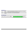
Printout of the Printer Settings
PRINT OUT? NO
→ or ← PRINT OUT? YES
↓
USER MACRO
PRINT OUT? NO
The setup is not printed.
PRINT OUT? YES
The printer setup is printed. The printout starts as soon as you select this value.
NOTE: The Program setup printout indicates:
• the currently selected values,
• the current selected macro is marked with the #x# symbols (USER MACRO #x#),
• the current firmware release.
78
User Macro
The USER MACRO item allows to prepare four printing environments (MACRO#1, MACRO#2,
MACRO#3 and MACRO#4). Each macro is composed of a group of parameters which define a
configuration that can then be recalled to easily set the printer for four printing environments.
Selection of the User Macro
PRINT OUT? NO
USER MACRO
↓
↑
MACRO#1
→ or ←
↓
MACRO#2
→ or ←
CONFIG MENU NO
MACRO#3
→ or ←
MACRO#4
→ or ←
USER MACRO
→
↓
LINE SP. 6 LPI
Selection of the macro for which you intend to set the parameters.
When a new macro is selected and the fanfold paper is present in the paper path set in the
previous macro, it will be automatically parked (TEAR IF NECESS/PARK PAPER is displayed).
Tear off this fanfold paper and press PARK key.
79
User Macro Parameters
U ser m a cro
M acro # 1
M acro #2
M acro # 3
M acro #4
Lin e sp. 6 lpi
Lin e sp. ...
Lin e S p. Lock N o
Lin e S p. Lock Yes
Len gth 66 Lines
Len gth ...
Top of F orm 0
Top of F orm …
Ign ore F.F. N o
Ignore F.F. Yes
S kipover 0
S kipover …
D raft M ode N orm
D raft M ode B est
Q u ality L Q
Q u ality N L Q
Fo nt D raft
Fo nt …
P itch 10 cpi
P itch …
15& 24 cpi M icro
15& 24 cpi N orm al
P itch Lo ck N o
P itch Lo ck Yes
Left M argin 0
Left M argin …
80
R ig ht M argin 136
R ig ht M argin …
S lash Ze ro No
S lash Ze ro Yes
P ath F ront 1
P ath …
Tear N orm al
Tear …
Tear D elay 1
Tear D elay …
E nable C utter
V T:F F + Cut
S tron g Im pact
S oft Im pact
P erfo r. Safe N o
P erfo r. Safe Yes
Q uiet Print Off
Q uiet Print On
A utogap 0
A utogap ...
Tuning: H oriz 0
Tuning: H oriz ...
Tuning: Vert 0
Tuning: Vert ...
M acro-> M FG N o
M acro-> M FG Yes
N ext M acro? No
N ext M acro? Yes
C onfig. Me nu N o
81
Line Spacing
MACRO#1
↑
MACRO#1
→
LINE SP. 6 LPI
→ or ←
LINE SP. 8 LPI
→ or ←
LINE SP. 12 LPI
→ or ←
LINE SP. 3L/30MM
→ or ←
LINE SP. 4L/30MM
→ or ←
LINE SP. 6L/30MM
→ or ←
LINE SP. 8L/30MM
→ or ←
LINE SP.12L/30MM
→ or ←
↓
LINE SP. LOCK NO
These values define the line spacing in lines/inch (6, 8, 12) or in lines per 30 mm (3, 4, 6, 8, 12).
Line Spacing Lock
LINE SP. 6 LPI
↑
LINE SP. LOCK NO
→ or ←
LINE SP. LOCK YES
→ or ←
↓
LENGTH xxx
LINE SP. LOCK NO
Setting this item, the value set for vertical spacing can be changed by software
or operator panel
LINE SP. LOCK YES
Setting this item, the value set for vertical spacing cannot be changed by
software but only by operator panel.
82
Page Length
LINE SP. LOCK NO
↑
LENGTH 1 LINE
→ or ←
LENGTH ... LINES
→ or ←
LENGTH 244 LINES
→ or ←
LENGTH A5
→ or ←
LENGTH A4
→ or ←
LENGTH A3
→ or ←
LENGTH A2
→ or ←
LENGTH LEGAL
→ or ←
LENGTH LETTER
→ or ←
↓
TOP OF FORM 0
These items set the page length for fanfold paper in number of lines depending on the current
vertical spacing. For the cut sheets the page format can be specified in number of lines or the
standard formats LETTER, LEGAL, A2, A3, A4, A5. Default value is 66 lines.
83
Top of Form
LENGTH xx
↑
TOP OF FORM 0
→ or ←
TOP OF FORM …
→ or ←
TOP OF FORM xxx
→ or ←
↓
IGNORE F.F. NO
These items set the top of form. The values range between 0 and the page length - 1.
Form Feed (FF) Command
TOP OF FORM 0
↑
IGNORE F.F. NO
→ or ←
IGNORE F.F. YES
→ or ←
↓
SKIPOVER 0
IGNORE F.F. NO
IGNORE F.F. YES
The Form Feed (FF) command is always executed.
The Form Feed (FF) command is ignored when the paper is in the top of form
(TOF) position. A Form Feed can be performed if the LOAD/FF key is pressed.
84
Skip Over Perforation
IGNORE F.F. NO
↑
SKIPOVER 0
→ or ←
SKIPOVER …
→ or ←
SKIPOVER xxx
→ or ←
↓
DRAFT MODE NORM
These items set the skipover perforation. The values range between 0 and the page length - 1.
Draft Print Mode Selection
SKIPOVER 0
↑
DRAFT MODE NORM
→ or ←
DRAFT MODE BEST
→ or ←
↓
QUALITY LQ
DRAFT MODE NORM The printer performs the draft printing at normal speed.
DRAFT MODE BEST
The printer performs the draft printing at low speed to obtain better quality
printing.
85
Quality Print Mode Selection
DRAFT MODE NORM
↑
QUALITY LQ
→ or ←
QUALITY NLQ
→ or ←
↓
FONT Draft
QUALITY LQ
The printer performs the Letter Quality printing.
QUALITY NLQ
The printer performs the Near Letter Quality printing.
Font Selection
QUALITY LQ
↑
FONT Draft
→ or ←
FONT Courier
→ or ←
FONT OCR-B
→ or ←
FONT Gothic
→ or ←
FONT Prestige
→ or ←
FONT Present
→ or ←
FONT OCR-A
→ or ←
FONT Script
→ or ←
↓
PITCH 10 CPI
Selects the fonts. OCR-A is displayed only if a non proportional pitch has been selected.
86
Pitch Selection
FONT Draft
↑
PITCH 5 CPI
→ or ←
PITCH 6 CPI
→ or ←
PITCH 7.5 CPI
→ or ←
PITCH 8.5 CPI
→ or ←
PITCH 10 CPI
→ or ←
PITCH 12 CPI
→ or ←
PITCH 15 CPI
→ or ←
PITCH 17.1 CPI
→ or ←
PITCH 20 CPI
→ or ←
PITCH 24 CPI
→ or ←
PITCH PROP
→ or ←
↓
15&24CPI MICRO
These items set the horizontal spacing in characters per inch. The PITCH PROP item sets
proportional character spacing.
87
Micro Dot Print Mode
PITCH 10 CPI
↑
15&24CPI MICRO
→ or ←
15&24CPI NORMAL
→ or ←
↓
PITCH LOCK NO
15&24CPI MICRO
The print matrix uses 8 x 8 dots only if the horizontal spacing is 15 or 24 cpi
(micro mode).
15&24CPI NORMAL The print matrix uses 12 x12 dots (normal mode).
Pitch Lock
15&24CPI MICRO
↑
PITCH LOCK NO
→ or ←
PITCH LOCK YES
→ or ←
↓
LEFT MARGIN 0
PITCH LOCK NO
PITCH LOCK YES
Setting this item, the pitch can be changed by software or operator panel.
Setting this item, the pitch can be changed ONLY by operator panel.
88
Left Margin
PITCH LOCK NO
↑
LEFT MARGIN 0
→ or ←
LEFT MARGIN ...
→ or ←
LEFT MARGIN xxx
→ or ←
↓
RIGHT MARGIN 136
The Left Margin is set in number of columns (depending on the current pitch) starting from the
physical left edge.
Right Margin
LEFT MARGIN 0
↑
RIGHT MARGIN. 2
→ or ←
RIGHT MARGIN. ...
→ or ←
RIGHT MARGIN. xxx
→ or ←
↓
SLASH ZERO NO
The Right Margin is set in number of columns (depending on the current pitch) starting from the
physical left edge. The default value is 136.
89
Zero Character Printing
RIGHT MARGIN 136
↑
SLASH ZERO NO
→ or ←
SLASH ZERO YES
→ or ←
↓
PATH FRONT 1
You can select the Zero character printing with or without a slash.
Paper Path Selection
This function defines the default paper path for the current macro.
SLASH ZERO NO
↑
PATH FRONT 1
→ or ←
PATH FRONT 2 (PRT9071 model)
→ or ←
PATH MANUAL FORM (PRT9070 model)
→ or ←
PATH PUSH PULL
→ or ←
CUT+ FRONT1 PUSH (PRT9070 model)
→ or ←
CUT+ FRONT PSHPUL (PRT9070 model)
→ or ←
PATH ASF1
→ or ←
PATH ASF2
→ or ←
PATH ASF3
→ or ←
↓
TEAR NORMAL
90
PATH FRONT 1
Paper loading with the Front1 push tractor (low position).
PATH FRONT 2
Paper loading with the Front2 push tractor (up position).This item is displayed only if
the Front2 push tractor option is installed (PRT9071 model only).
PATH MANUAL FORM Paper loading using manual cut sheet path (PRT9070 model only).
PATH PUSH PULL
Paper loading with the Front1 push tractor and the rear pull tractor. This item is
displayed if the rear pull tractor option is also installed.
CUT+FRONT1 PUSH
Paper loading using the manual paper path in overlay over the fanfold loaded with
the Front1 push tractor. The paper overlay function must be set to PAPER OVERLY
YES (PRT9070 model only).
CUT+ FRONT
PSHPUL
Paper loading using the manual paper path in overlay over the fanfold loaded with
the push-pull tractors. The paper overlay function must be set to PAPER OVERLY YES
(PRT9070 model only).
PATH ASF1
Paper loading from the first bin of the ASF option, if installed.
PATH ASF2
Paper loading from the second bin of the ASF option, if installed.
PATH ASF3
Paper loading from the third bin of the ASF option, if installed.
91
Tear-Off Mode
PATH FRONT 1
↑
TEAR NORMAL
→ or ←
TEAR AUTOMATIC
→ or ←
LABEL
→ or ←
TEAR NO
→ or ←
ENABLE CUTTER
→ or ←
↓
TEAR DELAY 1
TEAR NORMAL
The Tear-Off Function is performed pressing the TEAR key when the printer is
offline.
TEAR AUTOMATIC
When the printer is not receiving any data, the paper is moved to the Tear-Off
position. It is returned to the Tear-Off position as soon as it receives printing
data.
LABELS
This item must be set when printing on labels, in order to avoid paper jams.
The paper does not execute any backward movement. When pressing the PARK
key, the paper is ejected.
TEAR NO
The paper does not executes any backward movement.
ENABLE CUTTER
This selection enables the cutter option and appears only if the cutter option is
installed.
See also How to Use the Tear-Off Function and How to Handle the Paper Parking later in this
chapter.
92
Cutter Mode
This item is displayed only if the ENABLE CUTTER function is selected.
ENABLE CUTTER
↑
VT:FF + CUT
→ or ←
VT:LF + CUT
→ or ←
VT:VT
→ or ←
CUT EACH PAGE
→ or ←
CUT PAPER CHANGE
→ or ←
↓
ENABLE CUTTER
VT:FF + CUT
When the printer receives a VT command, it performs a form feed and then
cuts the paper.
VT:LF + CUT
When the printer receives a VT command, it performs a line feed and then
cuts the paper.
VT:VT
When the printer receives a VT command, it performs a vertical tabulation.
CUT EACH PAGE
Selecting this item, the printer cuts the paper at the end of each page
according to the selected page length.
CUT PAPER CHANGE Selecting this item, the printer cuts the paper when it receives a paper path
change command and passes over to the new paper path.
93
Tear Delay Mode
TEAR NORMAL
↑
TEAR DELAY 1
→ or ←
TEAR DELAY …
→ or ←
TEAR DELAY 5
→ or ←
↓
STRONG IMPACT
This item defines the time that printer uses to move paper to the Tear-Off position in automatic tear
mode. The range of the tear delay is between 1 and 5 seconds. The default value is 1 sec.
94
Print Impact Strength
TEAR DELAY 1
↑
STRONG IMPACT
→ or ←
SOFT IMPACT
→ or ←
↓
PERFOR. SAFE NO
STRONG IMPACT
The impact strength of the print head is set for printing on multicopy paper.
SOFT IMPACT
The impact strength of the print head is set for printing few copies.
The printing noise is reduced.
Paper Perforation
This function allows to move the print head aside the paper when the fanfold paper perforation passes
between the mylar and the print bar, to facilitate paper movement on critical forms.
STRONG IMPACT
↑
PERFOR. SAFE NO
→ or ←
PERFOR. SAFE YES
→ or ←
↓
QUIET PRINT OFF
The function is disabled. The print head remains in its position, when the
perforation of the paper passes.
PERFOR. SAFE YES The function is enabled. The print head is moved aside, when the perforation
passes.
PERFOR. SAFE NO
95
Quiet Printing
PERFOR. SAFE NO
↑
QUIET PRINT OFF
→ or ←
QUIET PRINT ON
→ or ←
↓
AUTOGAP 0
QUIET PRINT OFF
The function is disabled. Printing at normal noise level.
QUIET PRINT ON
The function is enabled. Printing at reduced noise level.
96
Adjusting the Distance of the Print Head
QUIET PRINT OFF
↑
AUTOGAP -5
→ or ←
AUTOGAP ...
→ or ←
AUTOGAP +3
→ or ←
MANUAL GAP
→ or ←
FIXED GAP 0.3
→ or ←
FIXED GAP ...
→ or ←
FIXED GAP 9.3
→ or ←
↓
TUNING:.HORIZ 0
AUTOGAP xxx
Selecting one of these values sensing the paper thickness. Negative values reduce
the distance between the print head and the paper. Default value is AUTOGAP 0.
MANUAL GAP
Selecting this item, the print head must be adjusted manually.
FIXED GAP xxx
Selecting one of these values the printer adjusts the print head gap to a fixed
distance.
97
Horizontal Character Tuning
AUTOGAP 0
↑
TUNING:HORIZ 0
→ or ←
TUNING:HORIZ ...
→ or ←
TUNING:HORIZ 60
→ or ←
↓
TUNING: VERT 0
These values adjust the distance between the left paper margin and the first print character. The
values correspond to 1/120 inch units, i.e. the tuning ranges between 0 and 0,5 inch.
Vertical Character Tuning
TUNING:HORIZ 0
↑
TUNING:VERT. -30
→ or ←
TUNING:VERT. ...
→ or ←
TUNING:VERT. 360
→ or ←
↓
MACRO -> MFG NO
These values adjust the distance between the top paper margin and the first printable line. The
values correspond to 1/180 inch units, i.e. the tuning ranges between -1/6 and 2 inch. 0 is the default
value.
98
Resetting the Macro Parameters to the Factory Defaults
TUNING:VERT. 0
↑
MACRO -> MFG NO
→ or ←
MACRO -> MFG YES
→ or ←
↓
NEXT MACRO? NO
MACRO -> MFG NO
The new values set for the macro parameters will be the used.
MACRO -> MFG YES The values set for the macro parameters will be reset to their factory defaults.
99
Selecting Another Macro
MACRO -> MFG NO
↑
NEXT MACRO? NO
↓
CONFIG MENU NO
→ or ←
NEXT MACRO? YES
↓
MACRO#1
To pass over to another macro, select NEXT MACRO YES. Pressing the ↓ or ↑ key the item MACRO#1
is displayed, then press the → key to pass over to MACRO#2 (MACRO CHANGING is displayed).
When passing over from one macro to another, the fanfold paper loaded from the paper path,
selected in the previous macro, will be automatically parked (TEAR IF NECESS/PARK PAPER is
displayed). Tear off this fanfold paper and press PARK key.
You can now set the parameters for MACRO#2 as described above. In this way you prepare the
second printing environment. Passing over from one macro to the other then sets two different
printing environments.
100
Passing over to the Power-On Configuration
At this point of the setup, it is possible to pass over to the Power On Configuration functions setting.
NEXT MACRO NO
↑
CONFIG MENU NO
→ or ← CONFIG MENU YES
↓
↓
HEX DUMP NO
EMUL. OPTIONS
These items are self-explaining.
Hexadecimal Dump
CONFIG MENU NO
↑
HEX DUMP NO
→ or ← HEX DUMP YES
↓
STORE? QUIT
If you select HEX DUMP YES, press the PROGRAM key to set this item. The hexadecimal printing
continues, until the HEX DUMP NO item is selected, entering again into the Program Setup.
101
Storing the values
HEX DUMP NO
↑
STORE? QUIT
→ or ←
STORE? SAVE
→ or ←
STORE? CURRENT
→ or ←
PROG
EXIT
STORE? QUIT
This setting does not save any of the new values set. The values set previously
will be used.
STORE? SAVE
The values set are stored permanently (in the NVM) and will be used until they
are changed by the operator.
STORE? CURRENT The values set are valid until the printer is turned off. When you turn the printer
on again, the values set in the preceding setup setup will be used.
At this point the Program Configuration Setup is finished. You exit pressing the PROGRAM key.
102
How to Select the Paper Path
The paper can be loaded into the printer using different paper paths. The messages indicating the
paper paths are shown only if the corresponding loading device is installed on the printer.
Proceed as follows:
1. Press the ON LINE key to put the printer offline (ON LINE indicator unlit).
2. Press the PATH key, according to the installed devices the following messages are displayed:
LOAD FRONT 1
For the paper path using the Front1 push tractor.
LOAD FRONT 2
For the paper path using the Front2 push tractor option (PRT9071 model only).
LOAD MANUAL
For the manual cut sheet paper path (PRT9070 model only).
LOAD PUSH-PULL For the paper path using the Front1 push tractor and the rear pull tractor option.
LOAD ASF1
Loading a cut sheet from the 1st bin of the Automatic Sheet Feeder (ASF) option.
LOAD ASF2
Loading a cut sheet from the 2nd bin of the Automatic Sheet Feeder (ASF) option.
LOAD ASF3
Loading a cut sheet from the 3rd bin of the Automatic Sheet Feeder (ASF) option.
• To load fanfold paper go to “Loading Paper Using the Front1 Push Tractor”, “Loading Paper
Using the Front2 Push Tractor (option)”, Loading Paper Using the Front1 Push Tractor and
the Rear Pull Tractor (option)”. When a new paper path is selected, the paper loaded in the
printer is automatically parked.
• To load manual cut sheets go to “Loading Cut Sheets”.
• For using paper with the Automatic Sheet Feeder option, consult the documentation you
receive together with the option.
103
How to Use the Tear-Off Function
This function is used to match the paper perforation with the tear-off bar. For this function the
following values must be set:
Selection of the Paper Size
1. Press the PROGRAM key when the printer is disabled or enabled without printing to enter the
Program Setup.
2. Press the ↓ key and the following message appears:
USER MACRO
3. Press the → key to select the macro for which you want to set the paper size (MACRO#1,
MACRO#2, MACRO#3 or MACRO#4).
4. Once the desired macro is displayed press the ↓ key until the following parameter is displayed:
LENGTH xx
5. Press the → or ← key until the desired page size is displayed.
6. Press again the PROGRAM key to exit the setup end set the new value.
104
Adjusting the Tear-Off Position
To check the Tear-Off Position proceed as follows:
1. Check if the paper perforation matches the tear-off bar on the printer.
2. To move manually the paper to the Tear-Off position, press the TEAR key when the printer is
enabled without printing (TEAR NORMAL function selected YES in the Program Setup).
You can leave the manual tear off function by pressing again the TEAR key.
If it does not:
1. Turn the printer off and press the PROGRAM key and hold it pressed while powering on the
printer until the RELEASE KEY message is displayed to enter the Power-On Configuration.
2. Press the ↓ key until the following message appears:
FUNCTIONS
3. Press the → key to enter and then press the ↓ until the following message is displayed:
TEAR ADJUST xxx
4. Press the → or ← key to scroll the values of this function.
The values below 0 move the tear-off position downwards, values above 0 move the paper
upwards. The values can be set between -30 and 360 at 1/180 inches (-1/6 to 2 inches).
5. When the desired value is displayed, press the PROGRAM key.
6. Press the PROGRAM key to save and exit from the setup.
105
Selection of the Tear-Off Mode
It is now possible to select the Tear-Off Mode.
1. Press the PROGRAM key when the printer is disabled or enabled without printing to enter the
Program Setup.
2. Press the ↓ key. The following message is displayed:
USER MACRO
3. Press the → key to select the macro for which you want to set the tear-off mode MACRO#1,
MACRO#2,MACRO#3 or MACRO#4).
4. Press the ↓ key, until the following message is displayed:
TEAR NORMAL
Pressing the → or ← key it is now possible to decide how to execute the tear off function:
TEAR NORMAL
Pressing the TEAR key the paper is moved to the tear-off position.
Pressing again the TEAR key to exit from the tear-off mode, the paper is
moved to the printing position.
TEAR AUTOMATIC If the printer is not receiving data, the paper is moved automatically to the
tear position.
LABEL
The TEAR key is disabled for the tear-off function. This selection is useful
when printing on labels. Pressing the PARK key, the printer ejects the paper
toward the back of the printer.
TEAR NO
The tear-off function is disabled.
5. Press the PROGRAM key to exit the setup.
106
How to Lock/Unlock the Printer Setups
To prevent not expertise persons changing the printer setup parameters, it is possible to lock/unlock
the access to the printer setups as follows:
• Press ON LINE, MACRO and ALTERNATE keys at the same time and keep them pressed while
powering the printer on. As soon as these keys are released, the following messages will be
displayed:
9070
then,
LOCKED MENU
Now the access to the printer setups is locked. If the PROGRAM key is pressed, the LOCKED MENU
message is displayed (the PROGRAM key is disabled).
• If you decide to unlock the printer setup, turn the printer off, then press the ON LINE, MACRO
and ALTERNATE keys at the same time and keep them pressed while powering the printer on
again. As soon as these keys are released, the following messages will be displayed:
9070
then,
UNLOCKED MENU
107
How to Handle the Paper Parking
According to the setting of the TEAR item in the Program Setup, the paper parking procedure is
performed in different ways. See the following description:
If TEAR NO is selected:
•
•
TEAR NO
When the paper is positioned at the first
printable line and the paper path is changed
(changing the Macro or pressing the PATH key)
or the PARK key is pressed, the printer
performs automatically the parking procedure.
If at least one line has been printed, or the
paper has been fed forward at least 1 line and
the paper path is changed (changing the Macro
or pressing the PATH key) or the PARK key is
IF
pressed, the display shows TEAR
NECESS./PARK PAPER.
If the paper to be parked is longer than 18"
tear it off and press the PARK key again to
perform the parking procedure.
1st printab le line
M ACRO or
PAT H o r
PA R K
PARKING
O ther pape r positio n
M ACRO or
PAT H o r
PA R K
TEAR IF NECESS.
PARK PAPER
PA R K
PARKING
108
If TEAR NORMAL is selected:
•
•
•
When the paper is positioned at the
first printable line and the paper
path is changed (changing the
Macro or pressing the PATH key) or
the PARK key is pressed, the
printer performs automatically the
parking procedure.
If at least one line has been
printed, or the paper has been fed
forward at least 1 line and the
paper path is changed (changing
the Macro or pressing the PATH
key) or the PARK key is pressed,
the paper is moved to the tear-off
position and the display shows
TEAR IF NECESS./PARK PAPER.
If the paper to be parked is longer
than 18" tear it off and press the
PARK key again to perform the
parking procedure.
TEAR NORMAL
1st printable line
O ther paper positio n
Print job
TE AR
M ACRO or
PATH o r
PAR K
PARKING
M ACRO or
PATH o r
PAR K
Paper is m ove d to
tear-off position
TEAR IF NECESS.
PARK PAPER
When the paper is positioned in the
tear-off position after pressing the
TEAR key, if you press the PARK
key
the
printer
performs
automatically
the
parking
procedure.
PAR K
PARKING
109
Paper is m ove d to
tear-off position
PAR K
PARKING
If TEAR AUTOMATIC is selected:
•
•
•
When the paper is positioned at the
first printable line and the paper path
is changed (changing the Macro or
pressing the PATH key) or the PARK key
is pressed, the printer performs
automatically the parking procedure.
If at least one line has been printed, or
the paper has been fed forward at least
1 line and the paper path is changed
(changing the Macro or pressing the
PATH key) or the PARK key is pressed,
the paper is moved to the tear position,
the display shows TEAR IF NECESS./
PARK PAPER. If the paper to be parked
is longer than 18" tear it off and press
the PARK key again to perform the
parking procedure.
TEAR AUTOMATIC
1st printab le line
O ther pape r positio n
M AC R O o r
PATH o r
PAR K
PARKING
P aper m oved to
tear-off position
M AC R O o r
PATH o r
PAR K
P aper m oved to
tear-off position
M AC R O o r
PATH o r
PAR K
If at least one line has been printed, or
the paper has been fed forward at least
1 line and the paper path is changed
(changing the Macro or pressing the
PATH key) or the PARK key is pressed
when the paper is already in the tear
position,
the
printer
performs
automatically the parking procedure.
TEAR IF NECESS.
PARK PAPER
PAR K
PARKING
110
PARKING
If LABEL is selected:
•
•
LABEL
When the paper is positioned at the
first printable line and the paper path
is changed (changing the Macro or
pressing the PATH key), or the PARK
key
is
pressed
the
printer
automatically ejects the paper towards
the rear of the printer.
1st printab le line
If at least one line has been printed, or
the paper has been fed forward at least
1 line and the paper path is changed
(changing the Macro or pressing the
PATH key) or the PARK key is pressed,
the
display
shows
TEAR
IF
NECESS./EJECT PAPER. If the paper
to be ejected is longer than 18" tear it
off and press the PARK key again to
perform the paper ejection.
MACRO or
PATH o r
PAR K
EJECTING
Other paper position
MACRO or
PATH o r
PAR K
TEAR IF NECESS.
EJECT PAPER
PAR K
EJECTING
111
If at power on the paper is already loaded in a paper path that is different to the paper path
used by the macro which is valid at power-on, independently from the setting of the TEAR
function, the display shows TEAR IF NECESS./EJECT PAPER. If the paper to be ejected is
longer than 18" tear it off and press the PARK key again to perform the paper ejection.
In all the above cases the parking procedure may be interrupted pressing the ALTERNATE key.
The display shows OPER. INTERRUPTED.
If in any of the above cases you do not tear off the paper and the printer is not able to park it,
because it is too long, the display shows TEAR OFF PAPER/PARK PAPER. Tear off the paper and
press again the PARK key.
During the parking procedure the display shows PARKING. If the printer is ejecting the paper
(see LABEL selection) the display shows EJECTING.
112
Paper Handling
Paper Paths
M anua l P a th
(P R T90 70)
F ront1 P ush P ath
(P R T90 70 and P RT 90 71)
Base C onfig uration
W ith Installed Option
F ront1 P ush Tra ctor
plus Cu tter
(P R T90 70 and P RT 90 71)
P ush-P ull P ath
(P R T90 70 and P RT 90 71)
A utom atic S h eet F eede r
plus
F ront1 P ush Tra ctor
(P R T90 70 and P RT 90 71)
F ront2 P ush Tra ctor
plus Cu tter
(P R T90 71)
F ront2 P ush P ath
(P R T90 71)
113
Paper Specifications
It is important to use the correct paper for obtaining the best performance. See the information table
below:
Fanfold Paper (PRT9070 and PRT9071 models)
Loading Mode
Front1 Tractor
Front2 Tractor option
(PRT9071 model only)
Push-Pull option
Width
76 to 432 mm
3 to 17 inches
76 to 432 mm
3 to 17 inches
76 to 432 mm
3 to 17 inches
Length
76 to 609 mm
3 to 24 inches
76 to 609 mm
3 to 24 inches
76 to 609 mm
3 to 24 inches
Thickness
max.0.635 mm
0.025 inches
max. 0.635 mm
0.025 inches
max. 0.3 mm
0.014 inches
1+7
1+7
1+7
- Original
55 to 150
55 to 150
55 to 150
- Other sheets
45 to 75
45 to 75
45 to 75
- Carbon Paper
35
35
35
Copies
2
Weight (g/m ):
Envelopes (PRT9070 model only)
Loading Mode
Manual Feeding
Length
102 to 559 mm (4 to 22 inches)
Thickness
Max. variations 3 mm (0.013 inches)
Types
USA 6 (165 x 92 mm)
USA 10 (241 x 105 mm)
114
Cut Sheets (PRT9070 model only)
Loading Mode
Manual Loading
Width
114 to 432 mm (4.5 to 17 inches)
Length
101 to 559 mm (4 to 22 inches)
Weight
Original:
50-120 g/m
Multiparts:
First Sheet:
55-75 g/m
Other Sheets:
45 - 75 g/m
Carbon Paper:
14 - 35 g/m
A5
149 x 210 mm
Portrait & Landscape
A4
210 x 297 mm
Portrait & Landscape
A3
297 x 420 mm
Portrait & Landscape
A2
420 x 554 mm
Portrait
Letter
8.5 x 11 inches
Portrait & Landscape
Legal
8.5 x 14 inches
Portrait & Landscape
Executive
7.25 x 10.5 inches
Portrait & Landscape
Formats
2
Thickness
max. 0.635 mm (0.025 inches)
Copies
1 Original + 7 Copies
2
2
2
115
Cut Sheets
Cut Sheets Loading Modes
Cut sheet loading mode is only available for the PRT9070 printer model.
Cut sheets can be loaded manually, one at a time using the front manual paper path (manual or
automatic loading) or automatically using the ASF option for large quantities of paper.
Inserting a cut sheet, the fanfold paper is automatically parked with a reverse movement (if the
overlapping is not selected).
Loading Cut Sheets
1. Lift the cut sheets support until it locks in horizontal position.
116
2. Position the left paper guide on the cut sheet support for the first printing column (position 0).
3. Insert a cut sheet along the left paper
guide. Match the right paper guide with
the sheet margin.
117
4. The loading mode of the cut sheet depends on the value set for the QUICK function in the
Power-On Configuration:
Manual loading mode
(QUICK NO)
Make sure that the printer is disabled. Insert a cut sheet onto the front
paper support and press the LOAD/FF key to feed the paper. Press the
ON LINE key to enable the printer.
Automatic loading mode
(QUICK YES)
Insert a cut sheet onto the front paper support, the paper will be loaded
automatically after 2 seconds. The LOAD/FF key can be used to load the
paper into the printer, before the 2 seconds have passed.
5. To lower the paper feed support, free the
paper support holder below the support
and replace the support in its initial
position.
118
Fanfold Paper Loading
Loading Paper Using the Front1 Push Tractor
1. To select the Front1 push tractor paper path, press the PATH key. The display shows:
LOAD FRONT1
• If you have been using a different path, the display shows:
PATH CHANGING
• If you have been using fanfold paper in the Front2 push tractor paper path (if the Front2
push tractor option is installed), the printer automatically starts the parking procedure.
The display shows alternately:
TEAR IF NECESS.
and
PARK PAPER
• Tear off the fanfold loaded with the Front2 push tractor (if it is longer than 18 inches) and
press the PARK key. The display shows:
PARKING
followed by
LOAD FRONT1
119
2. Open the Push tractors cover turning it upwards and lay it on the top of the printer.
120
3.
Unlock the sprockets of the Front1 tractor moving the sprocket levers down. Slide the left
sprocket to the first printing column.
121
4. Space the paper guides along the tractor
bar. Open the left and right sprocket
covers.
5. Hold the fanfold paper in front of the
sprockets and insert the paper
perforation on the left sprocket pins
and close the left sprocket cover.
122
6. Insert the paper on the right sprocket
pins and close the right sprocket cover.
•
If you are using the 6 pin Front1 Push
tractor option, make sure the paper
goes under the paper sensor, and close
the right sprocket cover.
123
7.
Match the left sprocket for the first printing position, i.e. the left paper margin must match
the ninth mark on the printer cabinet.
9
1 2 3 4 5 6 7 8
124
8.
Adjust the right sprocket gently to remove slack from the paper.
Make sure the paper is not taut.
9.
Lock the left and right sprockets moving
the sprocket levers up.
125
10. Close the Push tractors cover.
Press the LOAD/FF key to load the paper into the printer.
The paper must be loaded as shown in figure.
126
Printer Maintenance and Troubleshooting
Cleaning the Printer
Make sure the printer has been turned off for at least 15 minutes before starting any cleaning
operations.
Periodic cleaning will help keep your printer in top condition so that it will always provide
optimal performance.
• Use a neutral detergent or water solution on a soft cloth to clean dirt and grease from the cabinet
of the printer.
• Do not use an abrasive cloth, alcohol, paint thinner or similar agents because they may cause
discoloration and scratching.
• Be especially careful not to damage the electronic and mechanical components.
127
Replacing the Ribbon Cartridge
1. Make sure that the printer is turned off for at least 15 minutes.
Pay attention to the print head because it becomes hot during operation.
2. Open the top printer cover.
3. Slide the ribbon guide out of the print head. If the color kit is installed on the printer, free the
shifter holder pushing the tab towards the rear and pulling the shifter holder up.
R ib b on G uide
Shifter H older
C olo r Sh ifter
128
4. Remove the used ribbon cartridge by lifting it up.
Black cartridge when the color kit option is not
installed
Black “Long Life” or Color cartridge when the
color kit option is installed
Now, you are ready to insert the new ribbon cartridge. See before
Installation".
129
"Ribbon Cartridge
Printing the Self Test
If you need to know any printer setting, and to check if the printer is working well, print the selftest.
Proceed as follows:
1. Keep the ON LINE key pressed while powering on the printer until the display shows
RELEASE KEY.
2. When you release the key, the printer starts the self-test printout.
3. To stop the self-test printing, press the ON LINE key again. The printer is offline.
130
Error Handling
When an error condition occurs:
• the printer is disabled;
• the first message on the display indicates the error, while the second message gives more
details concerning the error conditions.
Press always the ON LINE key to reset the error condition.
Error Message Description
Messages
Indication
Solution
A.G.A NOT OPER
ADJUST THE GAP
The automatic gap
adjustment (A.G.A) is not
enabled.
Press the ON LINE key to reset the error
condition. Adjust the print head gap to a
fixed distance. Select the print head fixed gap
adjustment function in the Program Menu.
• Press the PROGRAM key when the printer
is disabled (READY indicator unlit) to enter
the Program Setup.
• Press the ↓ key until the USER MACRO
function is displayed. Press the → key until
the desired macro is displayed (MACRO#x).
Press the → key to enter the macro
parameters. Press the ↓ key until the FIXED
GAP parameter is displayed. Press the → o ←
keys to select the fixed gap adjustment
values. From FIXED GAP 1 (simple fanfold
paper) to FIXED GAP 4 (multipart fanfold
131
Messages
Indication
Solution
paper).
BUFFER OVERFLOW A buffer overflow condition Turn the printer off and on again, or press
CHARACTER LOST
occurred (for the serial
the PROGRAM and ON LINE key successively
interface).
to clear the buffer.
CUT NOT ALLOWED
NUM.LINES < 12
An error occurred with the Turn the printer off and on again. If the error
optional cutter
is not solved, call the Customer Support.
DATA SET OFF
The DSR Signal is not
Press the ON LINE key to reset the error
connected to the printer
condition.
and is not ready for data
transfer (if the serial
interface is selected). This
condition may happen in a
remote connection (via
modem) and the DSR
(DATA SET READY)
signal is missing.
INTERLOCK ERROR
CHECK INSERTION
Neither the rear tractor
nor the tractor cover are
installed on the printer.
Install the rear tractor or the tractor cover on
the printer.
JAM FRONT1 PATH
CHECK PAPER
A paper jam error
condition occurred in the
Front1 paper path
Check the paper path and remove the
jammed paper. Press the ON LINE key to reset
the error condition.
JAM FRONT2 PATH
CHECK PAPER
A paper jam error
condition occurred in the
Front2 paper path
Check the paper path and remove the
jammed paper. Press the ON LINE key to reset
the error condition.
132
Messages
Indication
Solution
NO PATH AVAILABLE An electromechanical
Call Service.
failure occurs in the paper
paths.
NVM CHANGE
REMOVE PAPER
If this error is displayed
during the printer power
on, an NVM error
condition occurs
Turn the printer off and then on again. If the
problem is not solved call Service.
PAPER JAM
CHECK ALL PATHS
A paper jam error
condition occurs in the
paper path
Check all the paper paths and remove the
jammed paper. Press the ON LINE key to reset
the error condition.
PRINT INTEGRITY
Anomalous print out
¾Do not move the platen knob.
because of a possible print Press the ON LINE key to reset the error
carriage blocking
condition
RIBBON BLOCKED
CHECK RIBBON
The ribbon of the cartridge Check that the ribbon is correctly inserted.
is blocked
Turn the tension knob to make sure that the
ribbon is not jammed. Press the ON LINE key
to reset the error condition.
UNKNOWN
TRACTOR
A tractor type that is not
recognized has been
mounted on the printer.
133
Check that the installed tractor is compatible
with the printer.
Options
The Front2 Push Tractor
The Front2 Push Tractor (4 pin or 6 pin-type) is only available for the PRT9071 printer model.
An optional second front push tractor can be installed on the PRT9071 printer model. This
tractor allows the handling of a second fanfold paper.
Installing the Front2 Push Tractor
This second push tractor can be installed in front position on the Front1 Push tractor.
4 pin Front2 Push Tractor option
6 pin Front2 Push Tractor option with paper
sensor
134
1.
Align the hooks on both sides of the
Front2 push tractor with the pins on
the Front1 push tractor.
2.
Push the Front2 tractor until it is
fully engaged.
135
3. Insert the connector cable in the
electrical connector located in the
lower push tractor.
4.
Rotate the Front2 push tractor onto
the Front1 push tractor.
136
Removing the Front2 Push Tractor
If you need to remove the upper push tractor, turn the printer off. Disconnect the connector cable
and press on the push buttons to disengage the Front2 push tractor.
137
Loading Paper Using the Front2 Push Tractor (option)
1. To select the Front2 push tractor paper path press the PATH key until the display shows:
LOAD FRONT2
• If you have been using a different path, the display shows:
PATH CHANGING
• If you have been using fanfold paper in the Front1 push tractor paper path, the printer
automatically starts the parking procedure. The display shows alternately.
TEAR IF NECESS. and
PARK PAPER
• Tear off the fanfold loaded with the Front1 push tractor (if it is longer than 18 inches) and
press the PARK key. The display shows:
PARKING
followed by
LOAD FRONT2
138
2. Open the Push tractors cover turning it upwards and lay it on the top of the printer.
139
3. Unlock the Front2 push tractor sprockets
moving the sprocket levers up.
4. Space the paper guides along the tractor bar.
Open the sprocket covers of the left and right
sprocket.
140
5. Hold the fanfold paper in front of the
sprockets and insert the paper
perforation on the left sprocket pins and
close the sprocket cover.
6. Insert the paper on the right sprocket
pins and close the sprocket cover.
•
If you are using the 6 pin Front2 push
tractor option, make sure the paper
goes under the paper sensor and close
the sprocket cover
141
7. Position the left sprocket for printing, matching the left paper margin with the ninth notch
on the printer cabinet and lock it in place.
9
1 2 3 4 5 6 7 8
8. Adjust gently the right sprocket to remove slack from the paper.
142
9. Lock the Front2 tractor sprockets moving the
sprocket levers down.
10. Close the Push tractors cover.
11. Press the LOAD/FF key to load the paper into the printer.
143
Loading Paper Using the Front1 Push Tractor when the Front2 Push
Tractor (Option) is Installed
When the Front2 push tractor option is installed and you need load paper on the Front1 push
tractor follow this paper loading procedure:
1. Open the Push tractors cover turning it
upwards and lay it on the top of the
printer.
2. Rotate the Front2 push tractor option
outside the printer.
144
3. Insert the fanfold paper between the
Front1 and Front2 push tractor, then
proceed to load the paper as described
in the section Loading Paper Using the
Front1 Push Tractor.
4. When the fanfold paper has been
loaded on the Front1 push tractor,
reposition the Front2 push tractor in
its initial position before closing the
Push tractors cover.
5. Press the LOAD/FF key to load the paper into the printer.
145
The Rear Pull Tractor
An optional rear pull tractor can be installed on the printer. This tractor is useful to handle
particularly heavy paper.
Installing the Rear Pull Tractor
1. Turn the printer off.
2. Remove the ASF area cover, the rear pull tractor cover and the two small rear pull tractor
attachment area covers.
R e ar P ull Trac to r C o ve r
A S F A re a C ove r
R e ar P ull Trac to r
A ttac h m e nt A re a C ov e rs
Keep the covers in a safe place, as they must be reinstalled if the rear pull tractor is removed.
146
3. Replace the ASF area cover.
4. Open the top cover, free (1) the paper bail and remove (2) it from the hooks on both sides of
the printer.
5. Close the top cover.
1
1
2
147
6. Insert the rear pull tractor and the corresponding two small rear pull tractor attachment
area covers (with the slot) as shown in figure.
7. Turn the printer on.
148
Removing the Rear Pull Tractor
1. Turn the printer off.
2. Push the lever on the rear pull tractor down and lift the tractor out of the printer.
3. Insert the rear pull tractor cover and make sure that the interlock connector is correctly
inserted.
If the rear pull tractor cover is not inserted, the printer is blocked.
149
4. Open the top cover.
5. Move the print carriage to the right most position, then insert (1) the paper bail pins into the
hooks on both sides of the printer.
6. Rotate (2) the paper bail upwards and gently push it on both sides towards the back of the
printer until it clicks into place.
1
2
1
150
Loading Paper Using the Front1 Push Tractor and the Rear Pull
Tractor (option)
Once the rear pull tractor is installed, the fanfold paper can be loaded only in push-pull mode.
1. To select the Push-pull tractor paper path press the PATH key. The display shows:
LOAD PUSH-PULL
• If you have been using a different path, the display shows:
PATH CHANGING
• If you have been using fanfold paper in the Front2 push tractor paper path (if the Front2
push tractor option is installed), the printer automatically starts the parking procedure.
The display shows alternately:
TEAR IF NECESS.
•
and
PARK PAPER
Tear off the fanfold loaded with the Front2 push tractor (if it is longer than 18 inches)
and press the PARK key. The display shows:
PARKING
followed by
LOAD PUSH-PULL
151
2. Load the fanfold paper on the Front1 push tractor following the sequence Loading Paper
Using the Front1 Push Tractor described before.
3. Take up the slack of the paper exiting from the rear paper slot and open the left and right
sprocket covers. Unlock the sprockets moving the sprocket levers up.
4. Rotate the sprocket bar to align the sprocket pins with the paper perforation. Insert the
paper perforation on the left and right sprocket pins.
152
5. Close sprocket covers and lock the sprockets
moving the sprocket levers down.
6. Press the ON LINE key to confirm that the
paper loading is finished. The rear pull
tractor engages.
This figure shows the correct paper loading.
153
The Cutter
The cutter option allows to cut the paper automatically. It is installed on the rear of the printer.
For the installation of the cutter option and its corresponding paper grid, please refer to the
Installation Guide you receive together with this option. This figure shows the cutter position in
the printer.
Cutter option must be used together with 6 pin Front Push tractors (F1 and additionally F2).
Do not used with optional 4 pin F2 Push tractor.
The LAN Interface Board
A LAN Interface board is available for the network connections through an integrated Ethernet
10/100 Base-T interface, which coexists with the parallel interface.
For the installation of this board, please refer to the Installation Guide you receive together with
the Ethernet 10/100 Base-T board.
154
The Automatic Sheet Feeder (ASF)
The Automatic Sheet Feeder (ASF) option provides fast and automatic single sheet and
envelopes loading. It is installed on the rear of the printer. The ASF includes:
•
A standard paper stacker, which
automatically collects the output
paper.
•
A standard single bin for single sheets
(A5, A4, Letter, Legal, Executive) and
envelopes
•
Optional 2nd and 3rd bins are also
available.
For the installation of the ASF, please refer to the Installation Guide you receive together with
this option.
The figure shows the ASF position (with its accessories) in the printer.
155
The Color Kit
This printer can print not only in black but also in different colors.
For color printing you need the color kit option. The color or the black ribbon ‘Long Life’
cartridge can be used when the color kit is installed.
For the installation of this color kit you need an authorized technician.
The figure shows the color kit option (the color shifter).
156
The Printer Pedestals
For better paper handling, use the available printer pedestal options:
•
Three Levels Floor Pedestal, for large quantity and dual fanfold handling.
•
Two Levels Floor Pedestal, with tiltable printer level for document on demand application.
Three Levels Floor Pedestal
Two Levels Floor Pedestal
157
Printer Specifications
Printing Characteristics
Print Head
Matrix
24 pins - 0.25 mm
Print Head Life
700 mil characters (draft)
Print Speed (cps)
Draft
Quality
Normal
Best Draft
LQ
NLQ
10 cpi
700
400
133
262
12 cpi
840
480
160
315
micro 15 cpi
1050
600
200
393
normal 15 cpi
750
348
-
-
17,1 cpi
685
343
226
448
20 cpi
800
400
266
524
micro 24 cpi
960
480
320
629
normal 24 cpi
960
480
430 at 40 characters per line
300 at 80 characters per line
210 at 136 characters per line
Lines per minute @10 cpi
in Draft mode
-
Throughput (pages per hour)
ECMA 132
10 cpi
Draft
Quality
Normal
530
LQ
220
Best
465
NLQ
300
158
Print Matrix (horizontal x vertical)
Draft
Quality
Normal
Best Draft
LQ
NLQ
10 cpi
12 x 12
12 x 24
36 x 24
36 x 12
12 cpi
10 x 12
10 x 24
30 x 24
30 x 12
micro 15 cpi
8x8
8 x 16
24 x 16
24 x 8
normal 15 cpi
12 x12
12 x 24
-
-
17,1 cpi
14 x12
14 x 24
21 x 24
21 x 12
20 cpi
12 x 12
12 x 24
18 x 24
18 x 12
micro 24 cpi
10 x 8
10 x 16
15 x 16
15 x 8
normal 24 cpi
10 x 12
10 x 24
-
-
Print Density (characters per inch)
Normal
10 - 12 - 15 - 17.1 – 20 - 24
Line length (number of characters)
10 cpi
136
17.1 cpi
233
12 cpi
163
20 cpi
272
15 cpi
204
24 cpi
326
Vertical Spacing
6, 8, 12 lpi
3, 4, 6, 8, 12 lines/30 mm
n/62, n/72, n/180, n/216, n/360 per inch
159
Print Styles
Draft – Courier - OCR B - Gothic – Prestige – Present - OCR A - Script
Print Attributes
Sub-superscript, Underline, Overscore, Italics, Emphasized, Double Strike, Shadow, Enlarged, Compressed
Graphic Resolution (dots per inch)
horizontal
60, 80, 90, 120, 180, 240, 360
vertical
60, 72, 180, 360
Characters Sets
Standard PC IBM Character Sets
CS1 and CS2
EPSON National Variations
USA, France, Germany, United Kingdom, Denmark-1, Sweden, Italy, Japan,
Spain-1, Norway, Denmark-2, Spain-2, Latin America
IBM and EPSON Character Sets
USA (CP437), Greek (CP437-G), Slavic (CP437SL), Multilingual (CP850),
Greek (CP851), Eastern Europe (CP852), Turkish (CP 853), Cyrillic (CP855),
Turkish (CP857), Euro PC Multilingual (CP858), Portugal (CP860), Hebrew
(CP862), Canada/France (CP863), Arabic (CP864), Denmark/Norway
(CP865), Russian (CP866), Turkish2 (CP867), OCR-A (CP876), OCR-B
(CP877), Farsi (CP1098), Latin 2 Windows (CP1250), Cyrillic Windows
(CP1251), Latin 1 Windows (CP1252), Greek Windows (CP1253), Turkish
Windows (CP1254), Hebrew Windows (CP1255), Arabic Windows (CP1256),
Baltic Windows (CP1257), 96 GREEK, GOST, TASS, MAZOWIA,
UKRANIAN, KOI8-U
ISO Character Sets
8859/1 (Latin1), 8859/2 (Latin2), 8859/3 (Latin3), 8859/4 (Latin4), 8859/5
(Latin/Cyrillic), 8859/6 (Latin/Arabic), 8859/7 (Latin/Greek), 8859/8
(Latin/Hebrew), 8859/9 (Latin5), 8859/15 (Latin9)
160
Bar Codes
UPC-A, UPC-E, EAN-8, EAN-13, UPC-EAN 2, UPC-EAN 5, Code GP, MSI Plessey, Code BCD, C2/5-3 BAR,
Code 39, Code 128, Code 11, Code 93, Codabar, 2/5 Bidirectional, 2/5 Interleaved, 2/5 Industrial, 2/5 Matrix,
Postnet
Emulations
- EPSON LQ Series (ESC/P)
- IBM Proprinter XL24/XL24 AGM
- IBM Personal Printer 2391+
Standard Functions
• Automatic print head gap adjustment (AGA)
• Automatic paper path switching via operator panel or S/W commands
• Paper parking
• Plug & Play capability
• Bar Code printing
• Automatic fanfold positioning for tear-off , selectable time-out
• Setting and storage of paper format and print conditions for each paper path in the non volatile memory
• Printing of the macro characters using the Compuprint native commands
161
Paper Handling
PRT9070 Model - Base Configuration
FRONT1 PUSH TRACTOR
Fanfold Width:
76 to 432 mm
(3 to 17 inches)
Copies:
1 original + 7 copies
Max. thickness 0,635 mm (0.025 inches)
CUT SHEETS (loaded through the manual slot)
Sheet Width:
114 to 432 mm
(4,5 to 17 inches)
Standard Formats:
A5 - A4 - A3 - in portrait
Letter – Legal - Executive
Copies:
1 original + 7 copies
Max. thickness 0,635 mm (0.025 inches)
PRT9070 Model - Options
REAR PULL TRACTOR Option
Fanfold Width:
76 to 432 mm
(3 to 17 inches)
Copies:
1 original + 7 copies
Max. thickness 0,3 mm (0.014 inches)
Push-Pull Feeding: Front fanfold insertion with lower tractor in front push mode and rear tractor in pull mode.
AUTOMATIC SHEET FEEDER (ASF) Option
st
1 Bin
nd
Cut Sheets, envelopes and postcards
rd
2 and 3 Bins
Cut Sheets
Paper Stacker
Tray Capacity
120 sheets (80 g/m )
Sheet Width
88,9 to 304,8 mm (3,5 to 12 inches)
Copies
2
1 original + 2 copies
Coexisting with manual sheet and with fanfold in front push mode.
162
PRT9071 Model - Base Configuration
FRONT1 PUSH TRACTOR
Fanfold Width:
76 to 432 mm
(3 to 17 inches)
Copies:
1 original + 7 copies
Max. thickness 0,635 mm (0.025 inches)
PRT9071 Model - Options
FRONT2 PUSH TRACTOR Option
Fanfold width:
76 to 432 mm
(3 to 17 inches)
Copies:
1 original + 7 copies
Max. thickness 0,635 mm (0.025 inches)
REAR PULL TRACTOR Option
Fanfold width:
76 to 432 mm
(3 to 17 inches)
Copies:
1 original + 7 copies
Max. thickness 0,3 mm (0.014 inches)
Push-Pull Feeding: Front fanfold insertion with lower tractor in front push mode and rear tractor in pull mode.
AUTOMATIC SHEET FEEDER (ASF) Option
st
1 Bin
nd
Cut Sheets, envelopes and postcards
rd
2 and 3 Bins
Cut Sheets
Paper Stacker
Tray Capacity
120 sheets (80 g/m )
Sheet Width
88,9 to 304,8 mm (3,5 to 12 inches)
Copies
2
1 original + 2 copies
Coexisting with manual sheet and with fanfold in front push mode.
163
Physical and Electrical Characteristics
Interfaces
Parallel
Centronics Compatible Bi-directional (IEEE-1284) nibble and byte modes - 36 pin
Amphenol connector, 7/8 data bits
Receive Buffer: max. 128 Kbytes
Serial
RS-232/C and RS-422/A - dB 25 connector
Baud Rate: 300 to 38400 bps, 7/8 data bits, DTR & XonXoff flow
Receive Buffer: max. 128 Kbytes
Automatic interface switching
Reliability
MTBF
Mean Time between failure: 10000 hours at 25% DC
MTTR
Mean Time To Repair: 30 minutes
Workload
47000 pages/month (ECMA 132 - 4 hours for 22 days)
Printer Life
5 years or 10000 hours @25%
Duty Cycle
Operating: no limitations
Power Supply
UNIVERSAL
From 90 to 244 VAC
Power Output
Max. 154 W
Power Consumption
Standby: less than 30W ---- Average Printing: 116 W
Noise Level
< 54 dBA
164
Environment Conditions
Storage Conditions
Temperature
-40° to 50° C
Relative Humidity
10%t o 90% RH (non condensing)
Temperature
10° to 38° C
Relative Humidity
10 % to 90 % RH (non condensing)
Temperature
16° to 24° C
Relative Humidity
40% to 60% RH (non condensing)
Operating Conditions
Paper Conditions
Physical dimensions
Height
315 mm (12,21 inches)
Width
670 mm (26,18 inches)
Depth
390 mm (15,35 inches)
Weight
18 kg
Consumables
Black ribbon cartridge (15 million characters)
PRKN407-1
Black “Long Life” cartridge (20 million characters)
PRKN707-1
Color ribbon cartridge (2 million characters for each band)
PRKN408-1
165
Options
Color Kit
KITN401-000
Additional 4 pin Front2 Push Tractor (only for PRT9071 model)
PRFN900
Additional 6 pin Front2 Push Tractor (only for PRT9071 model)
PRFN103
Additional 6 pin Base Front1 Push Tractor
PRFN901
Additional 4 pin Rear Pull Tractor (for push-pull fanfold handling)
PRF9000
Ethernet 10/100 Base T LAN Interface Card
PRAN102
Cutter
PRFN088
Two Level Floor Pedestal (Tilt pedestal)
PRFN406-000
Three Level Floor Pedestal (Stationary pedestal)
PRFN405-000
Automatic Sheet Feeder (ASF) with envelopes and sheet stacker
PRFN401-000
Nd
rd
2 and 3 ASF Bins
PRFN402-000
Standards
ESD IEC 801-2, CE Mark
UL 1950; CSA 22.2 n.950; FCC rules part 15, subpart J, class b
NEWKO-TSE (74-SEX) 203/92; EN 60950; IEC 950
VFG 243/91;VFG 46/92; VDE 875 cl.B; CISPR 22/EN 55022-class B
R.P.M. (cert. by VDE)
ISO 7779; ISO 9296
ECMA 8, 11, 132
166