1
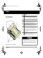
FSequence IPM Install Guide.book Page i Thursday, October 6, 2011 3:21 PM
TM
TM
Freedom Sequence with six AC relays
PN: 809-0912 shown.
Freedom Sequence
Intelligent Power Manager
Installation Guide
PNs: 809-0912
809-0913
FSequence IPM Install Guide.book Page ii Thursday, October 6, 2011 3:21 PM
FSequence IPM Install Guide.book Page i Thursday, October 6, 2011 3:21 PM
Trademarks
Product Numbers
Xantrex and Smart choice for power are trademarks of Schneider Electric Services
International sprl, registered in the United States and other countries. Other
trademarks, registered trademarks, and product names are the property of their
respective owners and are used herein for identification purposes only.
809-0912 (Six AC relays)
809-0913 (Four AC relays)
Notice of Copyright
Telephone:
1 800 670 0707
Freedom Sequence Intelligent Power Manager Installation Guide © August 2011
Xantrex Technology USA Inc. All rights reserved. No part of this document may be
reproduced in any form or disclosed to third parties without the express written
consent of: Xantrex Technology USA Inc., 541 Roske Drive, Suite A, Elkhart,
Indiana USA 46516. Xantrex Technology USA Inc. reserves the right to revise this
document and to periodically make changes to the content hereof without obligation
or organization of such revisions or changes unless required to do so by prior
arrangement.
Fax:
1 800 994 7828
Web:
www.xantrex.com
UNLESS SPECIFICALLY AGREED TO IN WRITING, XANTREX TECHNOLOGY USA INC. (“XANTREX”)
(A) MAKES NO WARRANTY AS TO THE ACCURACY, SUFFICIENCY OR SUITABILITY OF ANY
TECHNICAL OR OTHER INFORMATION PROVIDED IN ITS MANUALS OR OTHER DOCUMENTATION;
(B) ASSUMES NO RESPONSIBILITY OR LIABILITY FOR LOSSES, DAMAGES, COSTS OR EXPENSES,
WHETHER SPECIAL, DIRECT, INDIRECT, CONSEQUENTIAL OR INCIDENTAL, WHICH MIGHT ARISE
OUT OF THE USE OF SUCH INFORMATION. THE USE OF ANY SUCH INFORMATION WILL BE ENTIRELY
AT THE USER ’S RISK; AND
(C) REMINDS YOU THAT IF THIS MANUAL IS IN ANY LANGUAGE OTHER THAN ENGLISH,
ALTHOUGH STEPS HAVE BEEN TAKEN TO MAINTAIN THE ACCURACY OF THE TRANSLATION, THE
ACCURACY CANNOT BE GUARANTEED. APPROVED XANTREX CONTENT IS CONTAINED WITH THE
ENGLISH LANGUAGE VERSION WHICH IS POSTED AT WWW.XANTREX.COM.
Date and Revision
August 2011 Rev B
This guide for use by qualified installers only.
Exclusion for Documentation
Contact Information
To view, download, or print the latest revision, visit the website shown under Contact
Information.
Document Part Number
975-0594-01-01
975-0594-01-01
i
FSequence IPM Install Guide.book Page ii Thursday, October 6, 2011 3:21 PM
About This Guide
Purpose
Conventions Used
The purpose of this Installation Guide is to provide procedures for installing
and wiring the Freedom Sequence Intelligent Power Manager.
The following conventions are used in this guide.
Scope
The guide provides installation and mounting instructions, as well as
information on wiring the power manager.
It does not provide details about certain components that can be attached to
the power manager. You need to consult the individual component’s
owner’s guide for this information.
STATEMENT OF HAZARD
Contains statements of avoidance or strict compliance.
Failure to follow these instructions will result in death or serious
injury.
Audience
The guide is intended for qualified installers who need to install and mount
any unit model of the Freedom Sequence Intelligent Power Manager. The
installer should have knowledge and experience in installing electrical
equipment, knowledge of the applicable installation codes, and awareness
of the hazards involved in performing electrical work and how to reduce
those hazards. A qualified technician or electrician has this knowledge and
experience.
STATEMENT OF HAZARD
Contains statements of avoidance or strict compliance.
Failure to follow these instructions can result in death or serious
injury.
STATEMENT OF HAZARD
Contains statements of avoidance or strict compliance.
Failure to follow these instructions can result in minor or moderate
injury.
ii
Freedom Sequence Intelligent Power Manager Installation Guide
FSequence IPM Install Guide.book Page iii Thursday, October 6, 2011 3:21 PM
STATEMENT OF HAZARD
Failure to follow these instructions can damage the unit and/or
damage other equipment.
IMPORTANT: These notes describe things which are important for you to
know, however, they are not as serious as a danger, warning, or caution.
Related Information
You can find more information about Xantrex Technology USA Inc. as well
as its products and services at www.xantrex.com.
The product marking on the left when found imprinted on
electrical and electronic units and appliances means that you
are to refer to this guide for cautions and warnings.
975-0594-01-01
This guide for use by qualified installers only.
Contains statements of avoidance or strict compliance.
iii
FSequence IPM Install Guide.book Page iv Thursday, October 6, 2011 3:21 PM
Important Safety Instructions
IMPORTANT: READ AND SAVE THIS INSTALLATION GUIDE FOR
FUTURE REFERENCE.
This chapter contains important safety instructions when operating the
Freedom Sequence Intelligent Power Manager. Each time, before using the
Freedom Sequence Intelligent Power Manager, READ ALL instructions
and cautionary markings on or provided with the power manager and all
appropriate sections of this guide.
NOTE: The Freedom Sequence Intelligent Power Manager contains no userserviceable parts. For obtaining service, see “Warranty and Return
Information” on the Owner’s Guide for guidance.
NOTE: The Freedom Sequence Intelligent Power Manager must be provided
with grounding conductors connected to the AC input/output connections.
ELECTRICAL SHOCK HAZARD
•
•
•
•
•
Do not expose the power manager to rain, snow, spray, or bilge water.
Do not operate the power manager if it has received a sharp blow,
been dropped, has cracks or openings in the enclosure, or will not
close, or otherwise damaged in any other way.
Do not disassemble the power manager.
Disconnect both AC and DC power from the power manager before
attempting any maintenance or cleaning or working on any circuits
connected to the power manager. See note below.
Do not operate the power manager with damaged or substandard
wiring. Make sure that all wiring is in good condition and is not
undersized. Use copper conductors only.
Failure to follow these instructions will result in death or serious
injury.
NOTE: The power manager has no on/off switch. Circuits are always live
when DC and AC input are present.
iv
Freedom Sequence Intelligent Power Manager Installation Guide
FSequence IPM Install Guide.book Page v Thursday, October 6, 2011 3:21 PM
Precautions When Placing the Power Manager
EXPLOSION HAZARD
Failure to follow these instructions will result in death or serious
injury.
NOTE: Follow these instructions and those published by the battery
manufacturer and the manufacturer of any equipment you intend to use in
the vicinity of the battery. Review cautionary markings on these products
and on the engine.
PERSONAL INJURY HAZARD
This power manager is not intended for use by persons (including
children) with reduced physical, sensory, or mental capabilities or lack of
experience and knowledge, unless they have been given supervision or
instruction concerning use of the appliance by a person responsible for
their safety. Children should be supervised to ensure that they do not play
with the power manager.
Failure to follow these instructions can result in death or serious
injury.
975-0594-01-01
EXPLOSION HAZARD
Do not place the power manager in machinery space or in areas
containing gasoline tanks or fittings in which ignition-protected
equipment is required.
This equipment is intended for installation in accordance with the
National Electrical Code, NFPA 70.
Failure to follow these instructions will result in death or serious
injury.
ELECTRICAL SHOCK HAZARD
To reduce the risk of fire or electric shock, install in a controlled
environment relatively free of contaminants.
Failure to follow these instructions can result in death or serious
injury.
NOTE: A controlled environment is an environment that is relatively free of
solid airborne particulates, liquid, and/or gaseous elements. A controlled
environment may also be provided by means of a totally closed, gasketed
enclosure or the equivalent.
This guide for use by qualified installers only.
Do not work in the vicinity of lead-acid batteries. Batteries generate
explosive gases during normal operation. See note below.
v
FSequence IPM Install Guide.book Page vi Thursday, October 6, 2011 3:21 PM
FCC Information to the User
RISK OF DAMAGE TO THE POWER MANAGER
•
•
Never place the Freedom Sequence Intelligent Power Manager unit
directly above batteries; gases from a battery will corrode and
damage the power manager.
Do not place a battery on top of the power manager.
Failure to follow these instructions can damage the unit and/or
damage other equipment.
This equipment has been tested and found to comply with the limits for a
Class B digital device, pursuant to part 15 of the FCC Rules. These limits
are designed to provide reasonable protection against harmful interference
in a residential installation. This equipment generates, uses, and can radiate
radio frequency energy and, if not installed and used in accordance with the
instructions, may cause harmful interference to radio communications.
However, there is no guarantee that interference will not occur in a
particular installation. If this equipment does cause harmful interference to
radio or television reception, which can be determined by turning the
equipment off and on, the user is encouraged to try to correct the
interference by one or more of the following measures:
•
Reorient or relocate the receiving antenna.
•
Increase the separation between the equipment and receiver.
•
Connect the equipment into an outlet on a circuit different from that to
which the receiver is connected.
•
Consult the dealer or an experienced radio/TV technician for help.
Unauthorized changes or modifications to the equipment could void the
user’s authority to operate the equipment.
vi
Freedom Sequence Intelligent Power Manager Installation Guide
FSequence IPM Install Guide.book Page i Thursday, October 6, 2011 3:21 PM
Contents
Important Safety Instructions . . . . . . . . . . . . . . . . . . . . . . . . . . . . . . . . . . . . . . . . . . . . . . . . . . . . . . . . . . . . . . . . . . . . . . . . . . . .iv
Introduction . . . . . . . . . . . . . . . . . . . . . . . . . . . . . . . . . . . . . . . . . . . . . . . . . . . . . . . . . . . . . . . . . . . . . . . . . . . . . . . . . . . . . . . . . 1
Features . . . . . . . . . . . . . . . . . . . . . . . . . . . . . . . . . . . . . . . . . . . . . . . . . . . . . . . . . . . . . . . . . . . . . . . . . . . . . . . . . . . . . . . . . . . . 5
Installing the Freedom Sequence . . . . . . . . . . . . . . . . . . . . . . . . . . . . . . . . . . . . . . . . . . . . . . . . . . . . . . . . . . . . . . . . . . . . . . . . 11
Freedom Sequence SCP Menu Map. . . . . . . . . . . . . . . . . . . . . . . . . . . . . . . . . . . . . . . . . . . . . . . . . . . . . . . . . . . . . . . . . . . . . . 18
Specifications . . . . . . . . . . . . . . . . . . . . . . . . . . . . . . . . . . . . . . . . . . . . . . . . . . . . . . . . . . . . . . . . . . . . . . . . . . . . . . . . . . . . . . . 19
FSequence IPM Install Guide.book Page ii Thursday, October 6, 2011 3:21 PM
FSequence IPM Install Guide.book Page 1 Thursday, October 6, 2011 3:21 PM
Introduction
Standard Features
•
•
•
•
•
•
•
•
1.The installer should have knowledge and experience in installing electrical equipment, knowledge of the applicable installation codes, and awareness of the hazards involved in performing electrical work and how to reduce those hazards. A qualified technician or electrician has this
knowledge and experience.
975-0593-01-01
Manage power for single or split-phase AC sources up to 50 amps
including 15-, 20-, 30-, and 50-amp shore and generator power
sources.
Fully user configurable AC and DC load management system using
the Xanbus System Control Panel (SCP).
Monitor current draw and On/Off status for each AC load circuit,
including the current draw from the main AC source (shore or
generator power).
Has six AC relays (PN: 809-0912) or four AC relays (PN: 809-0913)
via the AC relay terminal blocks which can control AC load circuits
rated up to 15 amps each.
Four DC relays (via the DC auxiliary connector port) which can
control external DC circuits based on Battery Voltage.
These four DC relays can also be used to control external AC circuits2.
Circuit level override from load-shed3 and priority swapping4, directly
accessible via the SCP.
Sequential engaging of AC loads for generator soft-start that
eliminates heavy inrush demand.
Seamless integration with Freedom SW Inverter/Chargers to provide
charger derating, automatic inverter assist, and auto-detect generator
run conditions and reset breaker rating from Shore to Generator
breaker rating.
This guide for use by qualified installers only.
The Xantrex Freedom Sequence Intelligent Power Manager is a fully
integrated power management system (sometimes referred to as EMS or
energy management system) that provides automatic power and load
management for use in recreational vehicles (RV) while receiving power
from a generator or shore power. The Freedom Sequence power manager
optimizes the available current capacity from an AC electrical source to
power as many connected AC loads as possible. It makes decisions on
which loads get power based on a priority base set by the installer1.
2.External AC circuits are AC loads that are not directly controlled through the Freedom Sequence’s available six (or four) AC relays.
3.Load shedding is defined as cutting power to loads that are drawing current from the system in
order to avoid an overload condition.
4.Priority swapping is defined as the automatic prioritization of loads when one load has been assigned a different priority number.
1
FSequence IPM Install Guide.book Page 2 Thursday, October 6, 2011 3:21 PM
Introduction
Material List
Freedom Sequence unit
The Freedom Sequence ships with the following items:
•
one Freedom Sequence unit,
•
owner’s and installation guides,
•
DC auxiliary connector wiring harness,
•
AC wiring terminal covers with screws, and
•
a Xanbus network terminator.
NOTE: Keep the carton and packing material in case you need to return
the power manager for servicing.
PN: 809-0912 shown
Owner’s and
installation guides
DC auxiliary
connector wiring
harness
network terminator
AC wiring terminal
covers with screws
2
Freedom Sequence Intelligent Power Manager Installation Guide
FSequence IPM Install Guide.book Page 3 Thursday, October 6, 2011 3:21 PM
Introduction
1
Compatible Products and Accessories
809-0915
25-ft network cable for SCP
809-0940
75-ft network cable for SCP
809-0942
lt
/
AC e Fau
er arg
ert Ch
Inv
On
The Xanbus System Control Panel (SCP) enables you to monitor and
control all the power components of the Freedom Sequence power manager
from a single easy-to-use interface.
The Xanbus Automatic Generator Start (AGS) is a panel and a control
module system that provides automatic activation for your generator. If the
AGS is present in the Xanbus network, the power manager does not need
the Generator Run signal (also known as switched B+ signal) to be
hardwired to the generator for it to receive generator-run conditions.
Together with the Freedom SW Series Inverter/Charger, the power manager
provides advanced power optimization features of interactive charger derating and automatic inverter assist to provide additional power to support
high peak power demands.
SCP
25-ft cable
75-ft cable
er
ert
Inv le
ab
En
Re
set
M
DO
EE
FR
SW
12
30
This guide for use by qualified installers only.
809-0921
Xanbus Automatic Generator Start (AGS)
30
12
Xanbus System Control Panel (SCP)
SW
815-2012, 815-2024 (2kW)
815-3012, 815-3024 (3kW)
O
M
Freedom SW Series Inverter/Charger
(12 and 24-volt systems)
Freedom
inverter/charger
ED
Product Number
FR
E
Product/Accessory
AGS
1.For an updated list, visit www.xantrex.com.
975-0593-01-01
3
FSequence IPM Install Guide.book Page 4 Thursday, October 6, 2011 3:21 PM
Introduction
Xanbus System
The Xanbus system includes the Freedom SW Series Inverter/Charger and
other Xanbus-enabled devices. The inverter/charger is the device in a
Xanbus system that typically provides network power—500 mA at 12 volts
DC. When Freedom Sequence is present in the network, it can also provide
the power for the whole Xanbus network. All of the Xanbus-enabled
devices, such as Freedom Sequence, the SCP, and the AGS are able to
communicate their settings and activity to each other. See Figure 1.
The Xanbus-enabled designation (see below) means that this product works
on a Xanbus network. Xanbus-enabled products are:
•
•
•
•
Simple to operate and routine tasks are automated,
Controlled by software that eliminates analog signalling errors,
Less susceptible to interference and line loss, and
Upgradable through new software releases.
AC Panel
For detailed instructions and a complete list of Xanbus-enabled devices,
visit www.xantrex.com.
Freedom Sequence
BATTERY
30
12
Shore
Power
SW
AC/ e Fault
er
Charg
Invert
On
er
Invert e
Enabl
M
D
O
FR
EE
System
Control
Panel
Automatic
Generator
Start
30
Reset
FR
EE
DO
M
12
SW
TM
TM
Inverter
Load Panel
Freedom SW Inverter/Charger
network
terminator
Generator
AC Loads
network
terminator
Figure 1 Typical Xanbus System Diagram
4
Freedom Sequence Intelligent Power Manager Installation Guide
FSequence IPM Install Guide.book Page 5 Thursday, October 6, 2011 3:21 PM
Features
Ports and Terminals
Item
Description
1
AC Main section contains the current and voltage sensors to
monitor the AC source and provides the pass-through wiring
from a transfer switch to the vehicle’s main distribution panel.
AC Main panel cover (removable for easy access)
Xanbus interface ports are used to connect Xanbus-enabled
devices including the SCP, AGS and Freedom SW.
DC auxiliary connector port contains the terminals for four
DC relays, Generator Run (B+) signal, and DC power.
AC relay three-wire terminal blocks provide six (or four)
Cage Clamp® connectors for connecting AC load circuits. One
load circuit corresponds to one AC relay. The relays are
bidirectional meaning, there are no designated AC IN and AC
OUT terminals.
Mounting holes are used for mounting the Freedom Sequence
unit. There are six holes provided on the unit.
2
3
1
2
3
4
4
5
6
5
ELECTRICAL SHOCK HAZARD
This guide for use by qualified installers only.
This section describes the different parts of the Freedom Sequence.
Disconnect all DC and AC power before opening the AC Main panel.
6
Failure to follow these instructions will result in death or serious
injury.
Figure 2 Freedom Sequence Ports and Terminals
975-0593-01-01
5
FSequence IPM Install Guide.book Page 6 Thursday, October 6, 2011 3:21 PM
Features
IMPORTANT: This illustration is not a detailed technical wiring schematic.
A
300A
NOTE: The Freedom Sequence power manager must
be permanently installed by a qualified installer in a
controlled environment.
Figure 3 shows a simple configuration where the
power manager is installed with a power supply line
(either shore or generator), one Freedom SW inverter/
charger, a Xanbus SCP, a Xanbus AGS, and various
electrical appliances in a typical RV. Means of overcurrent protection and disconnection must be incorporated into the fixed wiring, in accordance with the
electrical code that governs each installation.
Inverter/Charger
30
12
INVERTER
SUBPANEL
FR
EE
D
O
M
SW
r
Inverte
On
r
AC/
Fault
Charge
301
Inverte
Enable
2
SW
Reset
OM
ED
FRE
TM
BATT
SCP
MAIN AC
PANEL
TM
DC AUX
HARNESS
AGS
GEN RUN
(B+) SIGNAL
GENERATOR
30A
12V FUSE
PANEL
ALTERNATOR
R
DC
A
50A
Y2
ELA
DC RELAY 1
ISOLATOR
AC 1
START
AC 2
AC 4
AC 3
AC 5
AC 6
DC RELAYS
HOUSE
BATTERY
AC LINE
50A
DC LINE
XANBUS
AC DISCONNECT
300A DC DISCONNECT
TO SHORE
CONNECTION
Figure 3 Typical RV Wiring Diagram With Freedom Sequence (six-circuit model shown)
6
Freedom Sequence Intelligent Power Manager Installation Guide
FSequence IPM Install Guide.book Page 7 Thursday, October 6, 2011 3:21 PM
Features
Tools and Materials
Location
3.5mm blade long neck screwdriver for opening
the AC relay cage clamp connectors
Phillips screwdriver for removing and replacing
the AC Main panel cover
power drill/screwdriver
drill bit set for drilling pilot holes
wire stripper
Requirement
Dry
The power manager must be installed in a dry location not subject to
moisture especially rain, spray, or splashing bilge water.
The power manager should not be exposed to metal filings or any other
form of contamination.
The ambient air temperature should be between 0 – 50 °C (32 – 122 °F) for
best performance.
By definition, a controlled environment is clean and can be provided by
means of a totally closed, gasketed enclosure or the equivalent.
Clean
Cool
,
Materials
Qty
three-conductor plus bare ground AC Main cable – four-wire cable
(see recommendations on page 9)
two-conductor plus bare ground AC Relay cable – three-wire cable
(see recommendations on page 9)
wires to splice correspondingly with the wires on the supplied DC
auxiliary connector wiring harness
AC Main cable one-inch metal strain relief
M5 Phillips pan head mounting screw or drywall anchor or plasterboard
plug. Select the best mounting material suited to the type of surface.
M5 washers at 10mm OD max
as needed
975-0593-01-01
Condition
Controlled
Environment
as needed
as needed
EXPLOSION HAZARD
2
6
Do not place the power manager in machinery space or in areas
containing gasoline tanks or fittings in which ignition-protected
equipment is required.
6
Failure to follow these instructions will result in death or serious
injury.
This guide for use by qualified installers only.
Install the power manager in a location that meets the following
requirements:
Tools
7
FSequence IPM Install Guide.book Page 8 Thursday, October 6, 2011 3:21 PM
Features
Horizontally
Flat Surface
Figure 4 Mounting Orientations (Deck or Ceiling)
8
Figure 5 Mounting Orientations (Wall)
Freedom Sequence Intelligent Power Manager Installation Guide
FSequence IPM Install Guide.book Page 9 Thursday, October 6, 2011 3:21 PM
Wiring Requirements
ELECTRICAL SHOCK AND FIRE HAZARD
Do not operate the power manager with damaged or substandard wiring.
Make sure that all wiring is in good condition and is not undersized. A
qualified installer must be used. See notes below.
Failure to follow these instructions will result in death or serious
injury.
NOTES:
•
Wiring and fuse sizes are governed by electrical codes and standards.
Different requirements apply in different countries and to different
types of installations, for example, boat, home or RV. It is the
responsibility of the installer to ensure that each installation complies
with all applicable codes and standards.
•
Ensure that wires and fuses or breakered disconnects are correctly
sized.
•
According to the National Electrical Code, branch-circuit conductors
shall have an ampacity not less than the maximum load to be served.
“Where a branch circuit supplies continuous loads or any combination
of continuous and non-continuous loads, the minimum branch-circuit
conductor size, before the application of any adjustment or correction
factors, shall have an allowable ampacity not less than the noncontinuous load plus 125% of the continuous load.” However, an
exception to this rule is permitted “where the assembly, including the
overcurrent protection device (OCPD) protecting the branch circuit is
975-0593-01-01
IMPORTANT: Appliances and circuit breakers that are 100% rated will
have a listing on their product label similar to “Suitable For Use On SinglePhase ~AC circuits. For 100% Application.”
AC Breakers
Table 1 Recommended AC Breaker Sizes
AC Main circuit
Branch circuit
Type
Rating
toggle style AC circuit breaker
toggle style AC circuit breaker
50 A (max)
15 A (max)
This guide for use by qualified installers only.
Features
listed for operation at 100 percent of its rating, the ampere rating of
the overcurrent device shall be permitted to be not less than the sum of
the continuous load plus the noncontinuous load.” It is important to
note that every appliance (also referred to as “the assembly”) is listed
for operation at 100 percent of its rating as well as the circuit breaker
(“the OCPD”). The additional current flowing into the appliances will
cause additional heat. If the appliance or circuit breaker has not been
listed for 100% application, temperatures may easily become
excessive for the conductors and insulation.
In recognition of this exception, the Freedom Sequence allows you the
option to disable the Breaker Derating by changing the default
Enabled to Disabled in the Advanced Settings screen.
9
FSequence IPM Install Guide.book Page 10 Thursday, October 6, 2011 3:21 PM
Features
AC Wiring
Table 2 Recommended AC Cabling and Wiring Sizes
AC Main
AC Relay/s
Type
AWG
Rating
Romex® Copper SE Cable 3conductor with bare ground
Romex® Copper Branch Circuit
Cable 2-conductor with bare ground
6 – 10
each wire
50 A
12 each wire
15 A
Type
AWG
Rating
stranded and color-matched with the
wire/s on the DC auxiliary
connector wiring harness (as shown)
18
5A
DC Wiring
10
9
7
5
4
3
2
1
Y
RL
3
Y
RL
2
Y
6
RL
8
1
11
10
Y
13
12
Function
N/O*
Common
N/C**
N/O*
Common
N/C**
N/O*
Common
N/C**
N/O*
Common
N/C**
B+ sense
Common
NEG –
POS +
RL
15
14
Color
Orange
Brown
Blue
Orange
Brown
Blue
Orange
Brown
Blue
Orange
Brown
Blue
Yellow
Brown
Black
Red
B+
16
1
2
3
4
5
6
7
8
9
10
11
* Normally Open 12
** Normally Closed 13
14
15
16
BA
TT
DC wire/s
4
Table 3 Recommended DC Wiring Sizes
Freedom Sequence Intelligent Power Manager Installation Guide
FSequence IPM Install Guide.book Page 11 Thursday, October 6, 2011 3:21 PM
Installing the Freedom Sequence
Step 1: Mounting the Freedom Sequence
Be sure to read the safety guidelines and pay attention to all cautions and
warnings throughout the installation procedure. The installer is responsible
for ensuring compliance with the installation codes for your particular
application.
Installation Sequence
To make the installation quick and easy, Xantrex recommends that the
installation tasks be performed in the following sequence:
1.
Mount the Freedom Sequence.
2.
3.
4.
5.
6.
7.
8.
Connect the AC Main wires.
Connect the AC Relay wires.
Connect the DC Relay wires.
Interconnect the Xanbus components.
Turn on the SCP and bring the Freedom Sequence to Safe Mode.
Configure Freedom Sequence via the SCP.
Turn on the RV power system.
975-0593-01-01
Follow the requirements laid out under the section “Location” on page 7. To
begin, (1) place the Freedom Sequence on the surface to which it will be
installed and mark the mounting holes on the surface with a pencil. (2) Pilot
drill the holes, if necessary. (3) Secure the Freedom Sequence unit to the
surface using appropriate fasteners such as size M5 screws. Use the
recommended torque of between 4.0–4.4 Nm. Do not overtighten.
This guide for use by qualified installers only.
Overview
11
FSequence IPM Install Guide.book Page 12 Thursday, October 6, 2011 3:21 PM
Installing the Freedom Sequence
2-PHASE
PLUG
AC IN
AC OUT
AC IN
AC OUT
BREAKER 50A
ELECTRICAL SHOCK HAZARD
AC IN
MAIN AC
PANEL
Turn off switches and open all disconnects including circuit panel
breakers prior to wiring or servicing.
Failure to follow these instructions will result in death or serious
injury.
GENERATOR
30A
INVERTER
SUBPANEL
AC OUT
FIRE AND ELECTRICAL HAZARD
AC IN
Inverter/Charger
30
1
2
SHORE POWER
BATTERY
BREAKER
SW
r
r
M
O
D
EE
FR
Inverte
On
AC/
Fault
Charge
301
Inverte
Enable
2
SW
Reset
OM
ED
FRE
LAND-BASED
BREAKER 50A
2-PHASE
RECEPTACLE
AC IN
AC OUT
MAIN AC
PANEL
• Install in a controlled environment relatively free of contaminants.
• AC input wiring must be provided with a reliably grounded conductor.
• Compartments, raceways, and the like, for routing and stowage of conductors
connected in the field shall not contain rough, sharp, or moving parts that may
damage conductor insulation.
• Use only copper conductors, properly sized for the main 50-amp rated AC
input branch circuit, and the 15-amp rated AC relay branch circuits.
• All AC relay circuits must have a common disconnect and be connected to the
same pole of the disconnect (i.e. Main AC Panel).
Failure to follow these instructions can result in death or serious
injury.
Figure 6 Switch and Disconnect Locations
12
Freedom Sequence Intelligent Power Manager Installation Guide
FSequence IPM Install Guide.book Page 13 Thursday, October 6, 2011 3:21 PM
Installing the Freedom Sequence
Step 2: Connecting the AC Main wires
L1
N
L2
G
AC Main wires
Locate the two AC Main cable holes—one on each side of the power manager. Starting on one side,
(1) insert the threaded strain relief clamp into the cable hole. (2) Screw the ring fastener onto the
threads to secure the strain relief clamp in place. Repeat (1) and (2) on the other side. (3) Loosen the
screws of the strain relief clamp to allow the AC cable to be passed through.
Figure 7 Install the AC Strain Relief Devices
MAIN AC
PANEL
(1) Strip the phase and neutral wires of the AC Main cables as shown above. If the ground wire is
jacketed instead of bare, strip it as well as shown above. (2) Connect each wire of the AC cable meant
for the breakered AC transfer switch correspondingly into each slot on the power manager’s AC
terminal block. Use the recommended torque of between 18.0–20.0 Nm. Do not overtighten.
(3) Connect each wire of the AC cable meant for the main AC panel correspondingly into each slot
on the power manager’s terminal block. Use same torque as (2). (4) Connect the wires properly from
the other end of the AC cable in (2) to the AC transfer switch. (5) Connect the wires properly from the
other end of the AC cable in (3) to the main AC panel’s input line.
NOTE: In some cases, (1) to (3) are all that’s needed when (4) and (5) have already been done from
a previous installation.
This guide for use by qualified installers only.
AC Cable
10mm
L1
N
L2
G
Figure 8 Connect the Input and Output AC Main Wires
975-0593-01-01
13
FSequence IPM Install Guide.book Page 14 Thursday, October 6, 2011 3:21 PM
Installing the Freedom Sequence
Step 3: Connecting the AC Relay Wires
15A
8mm
N
G
L
e
l
ab
C
AC
AC relay wires
NGL
(1) Strip the phase and neutral wires of the AC cable to be used for the AC relays as shown above.
If the ground wire is jacketed instead of bare, strip it as well as shown above. (2) Open the AC
relay terminal’s cage clamp using a 3.5mm blade long neck screwdriver by inserting the tip
through the square hole.
14
(3) Starting with one end of an AC cable, connect each wire into a corresponding terminal on one
of the circuit breakers on the main AC panel. NOTE: The AC cable must be compatible with the
ratings of the circuit breaker to which it will be connected. (4) On the other end of the AC cable,
insert each wire into its corresponding cage clamp slot in the power manager’s AC relay terminal.
Once the wires have been properly inserted, close the cage clamp by removing the screwdriver.
(5) Tug the wires (soft-pull test) to make sure they are firmly in place. Correct any loosened
connections.
Freedom Sequence Intelligent Power Manager Installation Guide
FSequence IPM Install Guide.book Page 15 Thursday, October 6, 2011 3:21 PM
Installing the Freedom Sequence
Step 4: Connecting the DC Relay wires
1 Orange
2 Brown
3 Blue
N/O*
Common
N/C**
4 Orange
5 Brown
6 Blue
N/O*
Common
N/C**
7 Orange
8 Brown
9 Blue
N/O*
Common
N/C**
10 Orange
11 Brown
12 Blue
3
NOTE: The color of the wires on each DC device may be different
from the DC wiring harness’ wire colors. It is important to
match the functions of each wire and not rely on colors alone.
12
10 11
13 14
16
15
GENERATOR
30A
13 Yellow
B+ sense
14 Brown
Common
also known as Generator Run signal wire
B+
Y
RL
1
Y
* Normally Open
** Normally Closed
8
79
BATTERY
12V
15 Black (–)
16 Red (+)
BA
TT
4 6
5
2
RL
Y
3
2
1
B+
RL
Y
4
N/O*
Common
N/C**
RL
De
vi
ce
De
DC
(6) Use procedure (2) to open the cage clamp in the power manager’s opposite AC relay terminal.
Starting with another AC cable, insert each wire into its corresponding cage clamp slot. Once the
wires have been properly inserted, close the cage clamp by removing the screwdriver. (7) On the
other end of the AC cable, connect each wire into a corresponding terminal on the AC outlet. The
outlet can be used to connect an electrical appliance. A disconnect device is not needed nor
necessary.
vi
ce
DC
De
vi
ce
DC
De
vi
ce
DC
LGN
This guide for use by qualified installers only.
5mm
DC device wire/s
(1) Strip the DC device wires that will be used to connect to the DC Auxiliary wires as shown above.
(2) Connect the DC Auxiliary wires to DC devices that the power manager can control. (3) Connect
the Generator Run (B+) wires to a compatible generator. Consult the generator’s user manual for
more information. (4) Connect the BATT wires to a 12V battery. Connect red to the positive (+)
terminal first and then black to the negative (–) terminal.
975-0593-01-01
15
FSequence IPM Install Guide.book Page 16 Thursday, October 6, 2011 3:21 PM
Installing the Freedom Sequence
Step 5: Interconnecting the Xanbus Components
TM
Example 1
Step 6: Powering up the SCP
FSPM 00: Config
XANBUS INTERFACE
STACKING
INVERTER
ENABLE
RESET
FREEDOM SW
INVERTER AC/
ON CHARGE FAULT
INVERTER/CHARGER
TM
Mode
SHR BKR Mode
SHR BKR Rating
Circuit Config
[*Safe]
[Auto]
[30.0A]
INVERTER
SUBPANEL
AC OUT
AC IN
BATTERY
BREAKER
R
30
SCP
TM
AC IN
Example 2
XANBUS INTERFACE
STACKING
RESET
INVERTER
ENABLE
FREEDOM SW
r
Inverte
On
AC/ e
Charg
Fault
30
Inverte
Enable
12
SW
Reset
OM
ED
FRE
AC OUT
AC IN
DC AUX
HARNESS
TM
r
SW
EE
US
FR
C
M
INVERTER
ENABLE
O
RESET
D
STACKING
12
Inverter/Charger
XANBUS INTERFACE
AC OUT
MAIN AC
PANEL
INVERTER AC/
ON CHARGE FAULT
INVERTER/CHARGER
TM
BATT
AGS
TM
XANBUS INTERFACE
STACKING
RESET
INVERTER
ENABLE
R
C
US
(1) Pick the Xanbus SCP as the first Xanbus component in the network. Plug the SCP’s left Xanbus
network port with a network terminator. (2) Using a CAT5 network cable, plug the SCP’s right Xanbus
network port with one end of the network cable. Plug the other end of the network cable into the next
component’s left Xanbus network port. Daisy-chain the other components as shown. (3) Terminate
the daisy chain by plugging the right Xanbus network port of the last component with a network
terminator. NOTE: In a Xanbus network, the components’ arrangement is immaterial (see Example 2).
The only condition is that the first and last components need to be properly terminated.
16
(1) Close the DC battery disconnect to energize the Xanbus SCP. (2) Observe the Xanbus SCP’s
display panel, make sure it is receiving power from the system. (3) Bring the Freedom Sequence to
Safe Mode from the Config screen of the SCP. Refer to the Owner’s Guide for detailed instructions.
Freedom Sequence Intelligent Power Manager Installation Guide
FSequence IPM Install Guide.book Page 17 Thursday, October 6, 2011 3:21 PM
Installing the Freedom Sequence
Use the Freedom Sequence Owner’s Guide to configure basic and advanced
settings. To modify advanced settings on each circuit, refer to the Owner’s
Guide as well.
Step 8: Powering up the RV System
SHORE POWER
INVERTER
SUBPANEL
AC OUT
SCP
This guide for use by qualified installers only.
Step 7: Configuring Freedom Sequence
AC IN
TM
LAND-BASED
BREAKER 30/50A
BATTERY
BREAKER
30
12
Inverter/Charger
O
M
SW
r
D
2-PHASE
RECEPTACLE
r
Inverte
On
AC/
Fault
Charge
301
Inverte
Enable
2
SW
Reset
FR
EE
OM
ED
FRE
2-PHASE
PLUG
AC IN
AC OUT
AC IN
AC OUT
AC IN
BREAKER 50A
AC IN
DC AUX
HARNESS
AC OUT
MAIN AC
PANEL
B+ SIGNAL
BATT
AGS
TM
GENERATOR
30A
BATTERY
AC LINE
DC LINE
XANBUS
Connect the RV to shore power. (1) Close the land-based AC Breaker; (2) the transfer switch breaker
and; (3) all breakers in the main AC panel.
Lastly, bring the Freedom Sequence out of Safe Mode from the Config screen of the SCP to
Operating Mode. Refer to the Owner’s Guide for detailed instructions.
975-0593-01-01
17
18
NOTE: The Screens as shown in
this Menu Map are typical of the
six-circuit Freedom Sequence
model.
For example, in the Circuit Status
screen, a four-circuit Freedom
Sequence model will show only
eight circuits – four AC circuits
and four DC circuits.
AC Src Type
AC Source
L1 Amps
L2 Amps
Batt Voltage
Circuit Status
Config
Advanced Settings
FSPM 00: Status
Freedom Sequence Intelligent Power Manager Installation Guide
10
11
1
2
3
4
5
6
7
8
9
[Operating]
[Auto]
Mode
[30.0A]
Rating
Config
Defaults
[*Operating] or [Standby]
[*Auto] or [Manual]
[*30.0] [5.0] to [50.0]
[*Enabled] or [Disabled]
[*30.0] [5.0] to [50.0]
[*0] [1] to [120]
[*10] [4] to [60]
[*1] [1] to [10]
[*12.0V] or [24.0V]
[*1] [1] to [10]
[*Enabled] or [Disabled]
1
2
3
[10]
[Enabled]
[9]
[Enabled]
[8]
[Enabled]
[7]
[Enabled]
[6]
[Enabled]
Circuit Name
[ACLoad1]
Load Shed
[Enabled]
Circuit Type [ACInputOut]
AC Line
[Line1]
Priority
[2]
Reconnect MRGN
[10%]
GEN Soft Start
[Disable]
Batt Low Trig Set [10.5V]
Batt Low Trig Clr [11.0V]
Batt High Trig Clr [14.0V]
Batt High Trig Set [14.5V]
FSPM 00: Circuit 1
[*ACLoad1] see NOTE below
[*Enabled] or [Disabled]
[*ACInputOut] or [DCInputOut]
[*Line1] or [Line2] or [Batt1]
[*1] [1] to [10]
[*10] [1] to [100]
[*Disable] or [Enable]
[*10.5] [4.0] to [40.0]
[*11.0] [4.0] to [40.0]
[*14.0] [4.0] to [40.0]
[*14.5] [4.0] to [40.0]
4
5
6
7
8
9
6 ACLoad6
6 Priority
6 Load Shed
7 DCLoad1
7 Priority
7 Load Shed
8 DCLoad2
8 Priority
8 Load Shed
9 DCLoad3
9 Priority
9 Load Shed
10 DCLoad4
10 Priority
10 Load Shed
FSPM 00: Circuit Config
[5]
[Enabled]
[4]
[Enabled]
[3]
[Enabled]
[2]
[Enabled]
A
B
C
D
E
F
G
H
I
J
K
10
11
NOTE: Circuit names can be up to ten characters long. Valid characters are from a to z, A to Z, 0 to 9,
symbols '/' (forward slash) and '–'(hyphen). Spaces, an underscore, and a period are not accepted
symbols. Examples are “Main-A/C” and “Refrigerat”.
A
B
C
D
E
F
G
H
I
J
K
[Enabled]
BKR Rating
[30.0A]
GEN BKR Rating
[0sec]
GEN Warmup Delay
Connect Seq Delay [10sec]
AC Disq Priority
[2]
[12.0V]
Nom DC Voltage
Circuit1
Circuit2
Circuit3
Circuit4
Circuit5
Circuit6
Circuit7
Circuit8
Circuit9
Circuit10
FSPM 00: Advanced Settings
Mode
SHR BKR
SHR BKR
Circuit
Restore
FSPM 00: Config
1 ACLoad1
1 Priority
1 Load Shed
2 ACLoad2
2 Priority
2 Load Shed
3 ACLoad3
3 Priority
3 Load Shed
4 ACLoad4
4 Priority
4 Load Shed
5 ACLoad5
5 Priority
5 Load Shed
Cont
[1]
[Enabled]
FSPM 00: Circuit Config
FSPM 00: Circuit Status
Freedom Sequence SCP Menu Map
On 3.0A
1 ACLoad1
6.0A
1 Last Shed Current
On 4.5A
2 ACLoad2
4.0A
2 Last Shed Current
On 2.5A
3 ACLoad3
2.5A
3 Last Shed Current
On 2.3A
4 ACLoad4
2.0A
4 Last She Current
On 3.7A
5 ACLoad5
1.0A
5 Last Shed Current
On 3.0A
6 ACLoad6
4.0A
6 Last Shed Current
On N/A
7 DCLoad1
N/A
7 Last Shed Current
On N/A
8 DCLoad2
N/A
8 Last Shed Current
On N/A
9 DCLoad3
N/A
9 Last She Current
On N/A
10 DCLoad4
N/A
10 Last Shed Current
Freedom Sequence SCP Menu Map
Settings
1-Ph
Shore1
0.0A
0.0A
12.0V
Device Status Screen
Freedom Sequence SCP Menu Map
FSequence IPM Install Guide.book Page 18 Thursday, October 6, 2011 3:21 PM
FSequence IPM Install Guide.book Page 19 Thursday, October 6, 2011 3:21 PM
Specifications
NOTE: Specifications are subject to change without prior notice.
Physical Specifications
AC relay terminal
blocks
DC auxiliary
connector port
Electrical Specifications
254×355.6×63.5 mm (10×14×2.5 in.)
1 kg (2.2 lbs)
2
1 set of split-phase pass-thru terminals
(L1, N, L2, G) accessible by removing the
AC Main panel cover
6 pairs I/O terminal blocks - one pair for
each AC relay (PN: 809-0912)
4 pairs I/O terminal blocks - one pair for
each AC relay (PN: 809-0913)
4 (3-pin connector for each DC relay)
1 (2-pin connector for one Generator Run
signal)
1 (2-pin connector for battery)
AC Main input voltage
120/240 VAC single/split phase
AC Main input current
Split phase: 50 AAC per phase
Dual in phase: 30 AAC per phase
DC input voltage from
battery source
12/24 VDC
AC relay input voltage
120 VAC
AC relay input current
15 AAC per circuit
DC relays input voltage 12/24 VDC
DC relays input
current
5 ADC per circuit
Regulatory Approvals
Environmental Specifications
Operating range
975-0593-01-01
Safety
UL 916,
CSA C22.2 No. 205
EMC
FCC Part 15, Class B
–20 to 50 °C (– 4 to 122 °F)
This guide for use by qualified installers only.
Dimensions: L×W×H
Weight
Xanbus ports
AC Main
19
FSequence IPM Install Guide.book Page 20 Thursday, October 6, 2011 3:21 PM
FSequence IPM Install Guide.book Page i Thursday, October 6, 2011 3:21 PM
FSequence IPM Install Guide.book Page ii Thursday, October 6, 2011 3:21 PM
Xantrex Technology USA Inc.
1 800 670 0707 Tel
1 800 994 7828 Fax
www.xantrex.com
975-0594-01-01
Printed in China.