1
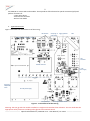
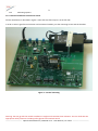
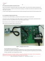
1 Test Jig Rev.3 for OPM-LD-yyy modules - User Manual Document date: 20 Jan. 2014 Contents: 1. 2. 3. 4. 5. 6. 7. 8. 9. 10. 11. 12. Scope Compatibility Jig board overview Power options Trigger source and signal connections Top/Left side calibrations and jumpers Top side DIP switches Monitors and LED indicators Communication channels Fan Operating instructions – Quick start Main connector pin-out 1. Scope: The scope of this document is to describe the test Jig rev.3 its functionality and operating instructions. 2. Compatibility The Test Jig test Jig rev.3 supports a range of OPM's products that come in forms of circuit boards or modules: 2.1 OPM-LDa series cards and modules. These products come with or without an integrated laser diode and they perform functions of – - Adjustable pulse generator with adjustable pulse width from 0.5ns to 1us (Depends on installed options). - Pulse driver - Efficient TEC controller 2.2 OPM-LD-ps series cards and modules. These products offer high resolution pulse shaping and perform functions of - Arbitrary waveform generator with sub-nanosecond resolution - Linear pulse driver - Efficient TEC controller - Built in laser diode - PC software and GUI to support pulse programming and monitoring functions Warning: the test jig with the module installed in it might emit hazardous laser radiation. The user shall take the appropriate safety measures including safety glasses and interlock switch. ----------------------------- Optical Pulse Machines / OPM-JIG rev.3 - User Manual / Jan. 2014 ----------------------------- 2 2.3 OPM-LD-Lin series cards and modules. These products offer electrical to optical conversion (E/O) and perform functions of - Linear pulse driver - Efficient TEC controller - Built in laser diode 3. Jig Board Overview Figure 1 describes the main elements of the test Jig. DIP Switches Serial prog. of Trigger generator pulse-width FAN Calibrations and disconnect jumpers LED indicators Module under test 5 ~ 32V power supply TP --------------------------------- Test Points ----------------------------------- AC power in 110/230VAC suppy AC to DC power supply Power jack input DC voltages terminal blocks GND Figure 1 - main elements of the test Jig Warning: the test jig with the module installed in it might emit hazardous laser radiation. The user shall take the appropriate safety measures including safety glasses and interlock switch. ----------------------------- Optical Pulse Machines / OPM-JIG rev.3 - User Manual / Jan. 2014 ----------------------------- 3 The unit under test (the module) shall be inserted in the middle of the test jig either vertically or horizontally with the optical output pointing to the left side. The 40 pin connector, J16, provides power and signaling lines to the unit under test. The DB9 connector, J13, above the 40 pin connector provides RS-232 or SPI serial communication. The connector may also be used for connecting to a PC USB port through an USB-RS232 adaptor. Such adaptor can be plugged directly to the DB9 connector. On the mid-top side the eight dip switches SW1 and SW2 are used for 8-bit programming of the pulse width for OPM-LDa modules with wide pulse-width option like the OPM-LDa-64 or OPM-LDa-256. The other four DIP switches, SW3, perform control functions. The push buttons SW6 and SW7 provide the means to program manually the pulse width of modules that require 2 line serial interface. With these two buttons no PC or controller is required for the programing. At the left side of the jig there are 4 calibrations. Each calibration is done by a potentiometer and each calibration may be disconnected by removing the shunt from the header. At the left bottom side the jig has a 110/230VAC main power input that feeds an internal 12VDC (could also be 20V or 24V) power supply. The output of this power supply is a coaxial power plug that shall be connected by the user to a power jack J28 at the the lower left side of the jig. The area below the LEDs in a variable power supply 5~32V. It can be used to control the amplitude signal of the module. For some modules the 32V might be hazardous and therefore in selected test jigs the voltage could be limited to a different voltage range (like 5V ~ 24V). Other power supplies on the jig are +5V, 3.3V (optional) and -3.3V (optional). The three DC terminal blocks at the bottom of the jig are used for power feeding of voltages individually. This is primarily for R&D purposes. The area right to the module is a trigger generator that includes an oscillator circuit with frequency controls. The generator triggers the module in various ways: internal trigger, external trigger or single trigger. The SMA connector above the module, J15 can be used for direct input to the driver section of OPM-LDa modules. In most cases this connector is not populated. Under the module there are 10 test points of main voltages and monitor points. At the right side of the jig there are six LEDs to provide main indications of power and module's failure. On the upper right corner a fan can be installed - optional. The push-button switch SW5 and the 8 pin connector J12 on the left are for future use. 4. Power options The various power inputs through the power jack J28 and the terminal blocks J33, J34, J35 and the jumpers J25, J26, J27 allow multiple power schemes. Perform the following described power settings prior to inserting the module to the jig. Warning: the test jig with the module installed in it might emit hazardous laser radiation. The user shall take the appropriate safety measures including safety glasses and interlock switch. ----------------------------- Optical Pulse Machines / OPM-JIG rev.3 - User Manual / Jan. 2014 ----------------------------- 4 4.1 Internal voltages First step shall be connection of the test jig's ground to your system or lab's ground. Use the black ground jack J31. The most simple power scheme is based on using the single 110/230 VAC power input and connect the jumpers in the jig properly. The internal power supplies in the jig provide the required voltages to the module. - Jumper J26 – connect a shunt at the upper position (this selects the jig's internal 5V voltage). - Jumper J25 - connect a shunt at the upper position (this selects the jig's internal 3.3V voltage). For the operation of OPM-LDa series modules the 3.3V voltage is not in use. - Jumper J27 - connect a shunt at the left position (this selects the TEC circuit voltage to be 5V). For the operation of modules with no TEC controller this is not in use. - Jumper J22 – connect a shunt at the left position to select internally generated voltage (5 to 32V) - Jumper J21: If the module under test has a 15V compliance voltage limitation – insert a shunt. - The R40 potentiometer sets the compliance voltage for the laser and controls the optical signal amplitude. You can monitor this voltage at the fuse – f1. - Connect the coaxial power connector of the 110/230VAC power supply to the power jack J28. - Connect the 110/230VAC power using an AC power cord (2 wire) to the AC power input at the left-bottom corner. NOTE: it is important to connect / disconnect the power using the 110/230VAC plug. 4.2 External voltages: For R&D tests that require variable power-supply voltages or special voltage values use the three terminal block connector pairs at the bottom side of the jig: J33, J34, J35. Set three jumpers in the following way: - Jumper J26 – connect a shunt at the lower position. This selects the jig's external 5V voltage through the terminal block J34. This power input is protected against reverse voltage and against overvoltage by a parallel zener diode. For enhanced circuit protection make sure that your external 5V source is set to current limit of 1.5A. - Jumper J25 - connect a shunt at the lower position. This selects the jig's external 3.3V voltage through the terminal block J35. For the operation of OPM-LDa series modules the 3.3V voltage is not in use. This power input is protected against reverse voltage and against overvoltage by a parallel zener diode. For enhanced circuit protection make sure that your external 3.3V source is set to current limit of 1A. - Jumper J22 – connect a shunt at the right position to select externally supplied voltage (5 to 32V) through the terminal block J33. This power input is protected against reverse voltage but it is not protected against overvoltage. Warning: the test jig with the module installed in it might emit hazardous laser radiation. The user shall take the appropriate safety measures including safety glasses and interlock switch. ----------------------------- Optical Pulse Machines / OPM-JIG rev.3 - User Manual / Jan. 2014 ----------------------------- 5 5. Trigger source and signal connections 5.1 The test jig offers three ways to trigger the module: external trigger, internal trigger using the jig's internal oscillator or single trigger using a push-button switch. 5.1.1 External trigger mode: Select the external trigger source by placing a shunt on jumper J19. The trigger provided externally at the SMA connector J23 will be active. The trigger shall be in levels of TTL or LVTTL. Do not exceed the voltage range from 0 to 5V. 5.1.2 Internal trigger mode: Select the internal trigger by placing a shunt on Jumper J37. The trigger signal comes from the jig's built-in oscillator with tunable frequency in the range of 4KHz to ~20MHz. The oscillator's frequency is controlled by the potentiometer R38 and the jumper J20. The jumper J20 has three positions: - Low frequencies, 4KHz to 0.2MHz - down position. Mid frequencies, 40KHz to 2MHz - disconnect the jumper. High frequencies, 400KHz to 20MHz: up position. See details in figure 2. OPM ships the jigs with frequencies calibrated to 10KHz / 100KHz / 1MHz – depends on the J20 position. 5.1.3 5.1.4 Figure 2 – On board oscillator Single trigger. A single trigger activated by a push button can be generated. Move the shunt to the jumper J36. Each push of the SW4 push-button generates a single trigger. An output trigger monitor is provided at the SMA connector J17. You may use this signal to trigger your oscilloscope (50 ohm or high impedance). 6. Left/top side calibrations and jumpers At the left/top side of the jig there are 4 calibrations. Each calibration is done by a potentiometer and each calibration may be disconnected by disconnecting the shunt of the near jumper: - Bias current: An analog voltage control (0 to 1V) for laser bias current in the range of 0 to 50mA. - Pulse width: An analog voltage control (0 to 2V) for fine pulse width variations up to approx. 3ns. The higher the voltage – the shorter the pulse-width. - Amplitude: An analog voltage control (0 to 2V) to change the high-voltage at the module's output stage. This results-in laser current changes with dynamic range of 5 or even more (Depends specifically on the module type). In most modules though the amplitude control in not implemented. - Set temperature – An analog voltage control (0 to 2.5V) to set the laser temperature through the TEC circuit. For a typical 10K NTC thermistor the set-temperature/voltage relationship is: Tset = (1.93-Vset)/0.027. OPM ships the jigs with Vset calibrated to 1.25V – corresponds to Tset = 25C. Warning: the test jig with the module installed in it might emit hazardous laser radiation. The user shall take the appropriate safety measures including safety glasses and interlock switch. ----------------------------- Optical Pulse Machines / OPM-JIG rev.3 - User Manual / Jan. 2014 ----------------------------- 6 Note that some modules already include potentiometers with the same calibrations. In that case in order to ensure proper operation disconnect the jumpers and use the calibration of the module. 7. Top side switches 7.1 Switches D0 ~ D7 The two left side quad switches form an eight bit word D0 ~ D7 to set the pulse width. Some of the OPM-LDa modules use 8 bits as a parallel world to control the pulse-width. Examples are OPMLDa-64, OPM-LDa-256. Other OPM-LDa series modules use only two data lines for pulse-width control : D0 and D1 (four PW settings). The eight bits are connected to the module with pull up resistors. 7.2 Four switches for control functions (Left to right): - TEC enable – This switch enables the TEC circuit. - Driver enable – This switch enables the driver, including the bias current and some of the module's internal reference voltages. - AE – Address Enable. This switch shall be brought to "1" while programming the digital word of the wide pulse generator of the OPM-LDa (for example 1ns to 256ns). - RES – Reset. Bringing this switch to"1" will reset the output of the wide pulse generator of the OPM-LDa (optional). One of the ordering options of the OPM-LDa module includes a generator with 22 bit serial word. The AE and RES lines in the jig also support this option. 7.3 Laser disable input J11 can be used as an extra disable input for the purpose of lab/system safety. Shorting the two pins of J11 disables the optical transmission. 7.4 Programing pulse-width using a manual serial interface: The push-buttons SW6 and SW7 can be used for programming the pulse-width data in a serial manner. This is applicable to the OPM-LDa-64/128/256 products if this option was ordered. SW6 acts as a clock and SW7 acts as data. Same functionality can be done using an external controller that is connected to the DB9 connector. See details in paragraph 9. 8. Monitors and LED indicators 8.1 The following monitor points are provided on the jig (under the module; left to right): - Ground, TP 18 +5V, TP 19 Warning: the test jig with the module installed in it might emit hazardous laser radiation. The user shall take the appropriate safety measures including safety glasses and interlock switch. ----------------------------- Optical Pulse Machines / OPM-JIG rev.3 - User Manual / Jan. 2014 ----------------------------- 7 -3.3V (generated by the jig), TP20 Peak laser current, TP21 Average laser current, TP22 Power (optical), TP23 3.3V, TP24 Temperature, TP 25 3/5V TEC, TP 26 Ground, TP 27 Another important monitor point is the 5 to 32V voltage. It shall be measured at the F1 fuse. The voltages shall be measured by DVM with input impedance of >10K ohm. 8.2 The following LED indicators are provided at the right side (top to bottom): - 5V – 32V 5V 3/5V TEC -3.3V 3.3V Module OK – indicates that the optical power is above the predefined threshold and that the TEC circuit has not failed. 9. Communication channels 9.1 The DB9 connector J13 is in charge of providing communication channels to the jig. It provides RS-232 or SPI or proprietary serial communication. For RS-232 the following table describes the 9 pins functionality. 9.2 Some of the pins got dual role – to support also SPI bus: Pin 3 (TD) is used as the SPI's SI line, pin 4 (TDR) is used as SPI's SC line and pin 8 (CTS) is used as SPI's SO line. 9.3 The DB9 connector may also be used for connecting to a PC USB port through an USB-RS232 adaptor. Such adaptor can be plugged directly to the DB9 connector. Warning: the test jig with the module installed in it might emit hazardous laser radiation. The user shall take the appropriate safety measures including safety glasses and interlock switch. ----------------------------- Optical Pulse Machines / OPM-JIG rev.3 - User Manual / Jan. 2014 ----------------------------- 8 10. Fan The jig may include a fan for modules with larger heat dissipation. The fan is not needed for OPM-LDa modules but it is required in some of the OPM-LD-ps modules. The air flow of the fan is aimed to the center of the module. For proper operation of the fan make sure that the fan has clearance of at least 3cm from any object. Don't touch the fan while operating! Use a shunt at the J3 jumper to activate the fan. 11. Operating instructions 11.1 Make sure the test equipment you use is grounded and the lab/personal has means of ESD protection. The following describes the operation of the test jig while using its internal power supplies. 11.2 - - General preparations: Connect the ground terminal of the test jig (J31) to your system's ground. Make sure that the following potentiometers are at minimum: Amplitude (CW all the way), Bias (CCW all the way) Set the jumpers J22, J25, J26 to internal mode and J27 to 5V: see paragraph 4.1. Trigger selection: Select the trigger source J19 (external) or J37 (internal) or J36 (single). Only one shunt shall be placed on J19 or J36 or J37. If external trigger then connect the trigger input (J23). As an extra precaution – set the frequency range J20 to the low position – 10K. Insert the fan switch shunt J3 – if required. Connect the 12V coaxial power plug to the power jack. Connect the 110/230V AC power. Make sure that the LED indicators for voltages are on. Set the required 5 to 32 voltage according to the requirements of the module under test. Turn off the power voltage by disconnecting the 110/230 VAC plug. Caution: The OPM-LD-yyy series modules were not designed for hot insertion. When inserting or removing the modules - make sure that the power is off. Insert the module to the jig – See mounting options in 11.3. Make sure that the optical output is oriented to the left side – as indicated on the test jig. Turn the power voltage on by the 110/230 VAC plug. Warning: the test jig with the module installed in it might emit hazardous laser radiation. The user shall take the appropriate safety measures including safety glasses and interlock switch. ----------------------------- Optical Pulse Machines / OPM-JIG rev.3 - User Manual / Jan. 2014 ----------------------------- 9 11.3 Mounting options: 11.3.1 Vertical installation of the driver board Vertical installation in described in Figure 3. Note that the fiber output is at the left side. In order to ensure good heat conduction and mechanical stability, use the mounting screws and the brackets. Figure 3 – Vertical mounting Warning: the test jig with the module installed in it might emit hazardous laser radiation. The user shall take the appropriate safety measures including safety glasses and interlock switch. ----------------------------- Optical Pulse Machines / OPM-JIG rev.3 - User Manual / Jan. 2014 ----------------------------- 11 11.3.2 Horizontal installation of the driver board Horizontal installation is possible only with some of OPM's modules. Note that the fiber output shall always be at the left side of the jig – as indicated. The horizontal mounting is not suitable for modules with a butterfly laser diode that require a heat-sink. In order to ensure good heat conduction from the module to the jig board use the three (or five) mounting screws. 11.3.3 Installation using an extension cord The extension cord allows flexibility in placement of the module in lab setups or system tests. The extension cord standard length is 50cm (Other lengths are available too upon request). The extension cord is especially useful when using modules with free-space transmission (no fiber). Note that the key of the connectors is at pin 40 (not pin 1). Figure 4 shows an installation with an extension cord. Figure 4 – Using the extension cord Using the OPM-LD-ps with extension cord: In test jigs that are shipped with OPM-LD-ps module the key of the 40 pin connector was removed. Therefore you must be very careful in connecting the extension cord to the test jig with the right polarity. pin #1 and #40 are clearly indicated on the test jig and on the cable. Warning: the test jig with the module installed in it might emit hazardous laser radiation. The user shall take the appropriate safety measures including safety glasses and interlock switch. ----------------------------- Optical Pulse Machines / OPM-JIG rev.3 - User Manual / Jan. 2014 ----------------------------- 11 11.4 Setting the trigger frequency (skip this part if you're using direct input): 11.4.1 You can monitor the trigger frequency using the trigger output signal at the SMA connector J17. 11.4.2 In case of using on-jig internal trigger oscillator: Set the frequency by tuning the potentiometer R38 and select the frequency range (J20). Select internal trigger by the jumper J37. See 5.1 for details on frequency ranges. 11.4.3 In case of using external trigger source: Set the external source to the required frequency. Levels shall be TTL or LVTTL. Select external trigger by the jumper J19. 11.5 - In case of using direct input (skip this part if you are using a trigger): Some of the OPM-LD-yyy modules support the feature of direct input. If your module supports this feature – Set the required waveform of your external test equipment. Make sure you don’t exceed voltage swing of 3Vpp. Make sure the duty cycle is smaller than the recommended one for the specific module under test (typically < 10%). Apply the signal through the J15 SMA connector. Don't apply trigger signal to the module (remove the shunt from J19, J36, J37). 11.6 Connect an oscilloscope with an optical input to the optical fiber of the module under test. 11.7 Enable the driver by setting the switches of SW3 to: TEC enable = 1, Laser enable = 1, RES = 1. Note that "1" state is where the switch points to the module (not to the board edge). If you have connected the laser-disable connector J11 then enable the laser by either disconnecting it or by bringing the signal voltage to TTL "1" state. From this point and on use the oscilloscope to monitor the waveform. 11.8 For short pulses or fine tuning set the pulse width using the "Fine PW" potentiometer R4. Turning R4 clockwise decreases the pulse width until it is gone. If you don't find a pulse turn R4 all the way in the counter-clockwise direction. 11.9 For modules with wider pulses (>5ns) – use the 8 bit (D0 ~D7) generator or the 22bit generator (requires SPI interface through the DB9 connector). Use the AE line to program the pulse and lock it. 11.10 If your module includes an amplitude control option then adjust the amplitude by R2. Otherwise - Use the R40 voltage-adjust potentiometer at the var. power supply section. If the voltage must be limited to 15V then insert a shunt in J21. 11.11 Set the required laser set temperature (If your module has a TEC) using the potentiometer R1. You can test the set voltage on the jumper j6. The voltage that represents the actual laser temperature can be tested in TP25. The voltage/temperature relation depends on the specific module under test. In most modules that include a 10K NTC thermistor the relation is: T(C) = (V-1.93)*37. For temperature of 25C the voltage is 1.25V. The OPM-LD-yyy modules come with a provided heat-sink that shall provide sufficient heat dissipation in lab conditions (10C to 40C). If you use the module in temperatures exceeding this range or if you calibrate the temperature to extreme values you may need to provide improved means to dissipate the heat: Fan or an extension to the heat-sink. Warning: the test jig with the module installed in it might emit hazardous laser radiation. The user shall take the appropriate safety measures including safety glasses and interlock switch. ----------------------------- Optical Pulse Machines / OPM-JIG rev.3 - User Manual / Jan. 2014 ----------------------------- 12 11.12 Set the required bias current (If your module has a bias option). You can test the set voltage on the jumper j9. The resulting bias current is V/20. For example 400mV will result in bias current of 20mA. Warning: the test jig with the module installed in it might emit hazardous laser radiation. The user shall take the appropriate safety measures including safety glasses and interlock switch. ----------------------------- Optical Pulse Machines / OPM-JIG rev.3 - User Manual / Jan. 2014 ----------------------------- 13 12. Main connector pin-out 41 Samtec connector SFM-120-01-L-D (note that the key is at pin 40) ... ... Current rating 3.9A (60C) 39 # Pin name Description Type Max. Current (mA) Voltage limits (V) . .4 . 2 . . . .3 . 1 Comments 1 Power 5–32V Output stage power Power 300 5 to 32 2 G 5-32V Ground Power 300 0 3 5V pulser and logic power Power 1000 4.75 – 5.25 4 G 5V Ground Power 1000 0 5 Module OK (out) If optical power monitor Out, TTL exceeds threshold than output goes TTL high 20 0–5 6 Driver enable Enable transmission of short pulses (<12ns). Active high. In, TTL 5 0-5 7 bias in Ib = Vb/20 In, analog 5 0-1 8 -3.3V -3.3V supply 500 -3.5 to 0 9 3.3V / TEC- 3.3V supply 2000 0 – 3.5 10 G Ground 11 TP General purpose test point 5 0-5 Test point TP13 12 TP 5 0-5 Test point TP15 13 --- Required stability +/- 2% Threshold may vary upon customer request Functionality of the two pins depends on the specific JIG2 order number Warning: the test jig with the module installed in it might emit hazardous laser radiation. The user shall take the appropriate safety measures including safety glasses and interlock switch. ----------------------------- Optical Pulse Machines / OPM-JIG rev.3 - User Manual / Jan. 2014 ----------------------------- 14 In, analog, AC coupled 100 0 – 5Vpp swing G 100 0 Resets the wide pulse generator. In, TTL 5 0–5 AE Address enable for programming the wide pulse generator. In, TTL 5 0–5 18 Trig in Pulse is initiated by rising edge in, TTL of incoming trigger. 100 0–5 19 D0 / - / CD Out D0 bit in 8 bit wide pulsewidth generator. TTL, in 5 0–5 TTL, in 5 0–5 14 In direct 15 GND 16 RES 17 Incoming pulse is converted to an optical pulse. The response is not guaranteed to be linear. Also D0 in 1-12ns generator 20 D1 / SI / TDin D1 bit in 8 bit wide pulsewidth generator. Option. Requires assembly changes. 50 ohm input impedance. Ensures a true 0 level at shutdown Pins 19 to 26 can be used in 3 ways: 8 bit parallel pulsewidth control or 3 line SPI control or RS-232 Option SPI, SI Also D1 in 1-12ns generator 21 D2 / - / RDout D2 bit in 8 bit wide pulsewidth generator. TTL, in 5 0–5 22 D3 / SC / DTRin D3 bit in 8 bit wide pulsewidth generator. TTL, in 5 0–5 23 D4 / - / DSRout D4 bit in 8 bit wide pulsewidth generator. TTL, in 5 0–5 24 D5 / - / RTSin D5 bit in 8 bit wide pulsewidth generator. TTL, in 5 0–5 25 D6 / SO / CTSout D6 bit in 8 bit wide pulsewidth generator. TTL, in 5 0–5 Option SPI, SC Option SPI,SO Warning: the test jig with the module installed in it might emit hazardous laser radiation. The user shall take the appropriate safety measures including safety glasses and interlock switch. ----------------------------- Optical Pulse Machines / OPM-JIG rev.3 - User Manual / Jan. 2014 ----------------------------- 15 26 D7 / - / RIout D7 bit in 8 bit wide pulsewidth generator. TTL, in 5 0–5 27 Fine PW Increasing the incoming voltage decreases the pulse width In, analog 5 0-2 28 Amplitude Controls the voltage supply of the OPM-LDa for the driver's output stage. In, analog 5 0 – 2.5 29 TP14 30 TP16 In OPM-LD-Lin acts as reset for digipot 5 0–5 31 TP17 In OPM-LD-ps and OPM-LD-Lin activates LPF #1 5 0–5 32 TP21 In OPM-LD-ps and OPM-LD-Lin activates LPF #2 5 0–5 option 33 Laser avg current Average laser current monitor monitor Out, analog 0.1 0–5 Shall be connected to impedance > 100K ohm 34 Photodiode monitor (power) V = Y x Po Out, analog 5 0-5 Y is according to the specific LD being used 35 Temperature monitor V = 1.93 – 0.027*T(C) Out, analog 5 0 – 2.5 Assuming NTC thermistor with 10K ohm, B=3900 36 Monitors GND Ground G 500 0 37 Set temperature Voltage sets the temperature of the TEC controller in, analog 5 0 – 2.5 38 TEC enable TEC enable - Active high In, TTL 5 0–5 39 5V TEC Supply for the TEC controller Power 2000 4.75 – 5.25 40 G 5V TEC Power 2000 0 option Voltage/temperature function is: V = 1.93 – 0.027*T(C) Warning: the test jig with the module installed in it might emit hazardous laser radiation. The user shall take the appropriate safety measures including safety glasses and interlock switch. ----------------------------- Optical Pulse Machines / OPM-JIG rev.3 - User Manual / Jan. 2014 -----------------------------