1
MHI-2000 Technical Reference
Manual
Rev A, January 2002
EM-63555-1A
MHI-2000 Technical
Reference Manual
Rev A, January 2002
Copyright © 2002 SICK Auto Ident, Inc.
This manual and the software described in it are copyrighted, with all
rights reserved. Under the copyright laws, no part of this publication may
be reproduced, stored in a retrieval system, or transmitted, in any form by
any means, electronic, mechanical, by photocopying, recording, or
otherwise, without prior written permission of SICK Auto Ident, Inc.
Information furnished by SICK Auto Ident, Inc. is believed to be accurate
and reliable and is subject to change without notice. However, no
responsibility is assumed by SICK Auto Ident, Inc. for its use or any
errors that may appear in this document, nor for any infringements of
patents or other rights of third parties, which may result from its use.
Factory Authorized Training
SICK Auto Ident, Inc. provides comprehensive product training. Contact
the SICK Auto Ident, Inc. Training Coordinator at 1-888-264-4641 for inhouse and on-site class schedules and rates.
Getting Assistance
If you have questions or comments, please contact SICK Auto Ident, Inc.
at 1-888-264-4641. For additional assistance, contact:
SICK Auto Ident, Inc.
5 Shawmut Road
Canton, MA 02021 USA
(781) 302-2500
Fax (781) 828-3150
•
Order Processing (Option #1)
•
Technical Support (Option #2)
•
Field Service Contracts (Option #3)
•
Customer Service Fax (781) 828-3150
Product names mentioned herein are for identification purposes only and
may be trademarks and/or registered trademarks of their respective
companies: OMNI, CiComm, CiFrame, CiMenu, CiMAX, CiPRO,
CiBOS, Scanstar, Starnode, and TALL Other references to trademarks are
the rights of their respective owners.
Printed in the United States of America.
Warning!
Warning!
WARNING! THIS EQUIPMENT GENERATES, USES, AND CAN RADIATE RADIO
FREQUENCY ENERGY AND, IF NOT INSTALLED AND USED IN ACCORDANCE
WITH THIS USER MANUAL, MAY CAUSE INTERFERENCE TO RADIO
COMMUNICATIONS. IT HAS BEEN TESTED AND FOUND TO COMPLY WITH THE
LIMITS FOR CLASS A COMPUTING DEVICES PURSUANT TO SUBPART J OF PART
15 OF FCC RULES, WHICH ARE DESIGNED TO PROVIDE REASONABLE
PROTECTION AGAINST SUCH INTERFERENCE WHEN OPERATED IN A
COMMERCIAL ENVIRONMENT. OPERATION OF THIS EQUIPMENT IN A
RESIDENTIAL AREA IS LIKELY TO CAUSE INTERFERENCE, IN WHICH CASE THE
USER, AT HIS OWN EXPENSE, MUST TAKE NECESSARY MEASURES TO CORRECT
THE INTERFERENCE.
THIS PRODUCT DOES NOT EXCEED THE CLASS A LIMITS FOR RADIO NOISE
EMISSIONS FROM DIGITAL APPARATUS SET FORTH IN THE RADIO
INTERFERENCE REGULATIONS OF THE CANADIAN DEPARTMENT OF
COMMUNICATIONS. (LE PRÉSENT APPAREIL NUMÉRIQUE N'ÉMET PAS DE
BRUITS RADIOÉLECTRIQUES DÉPASSANT LES LIMITES APPLICABLES AUX
APPAREILS NUMÉRIQUES DE LA CLASS A PRESCRITES DANS LE RÈGLEMENT
SUR LE BROUILLAGE RADIOÉLECTRIQUE ÉDICTÉ PAR LE MINISTÈRE DES
COMMUNICATIONS DU CANADA.)
Caution - Use of controls or adjustments or performance of procedures other than those
specified in this manual may result in hazardous exposure.
Attention - l’utilisation de procédures de contrôle, de reglage ou d’utilisation autres que celles
specifiées dans ce manuel peut entrainer une exposition dangereuse à la lumière du laser.
Peligro - El uso de controles, ajustes o funcionamiento diferentes a los especificados en este
manual pueden resultar en exposición a el rayo laser.
Waarschuwing - Afwijkend gedrag op de in net handboek beschreven procedure kan schok en/of bestralingsgevaar teweegbrengen.
Rev A, January 2002
MHI-2000 Technical Reference Manual
iii
Warning
Vorsicht: Veränderungen der Justierungen oder Einstellungen, sowie sonstige
Veränderungen die nicht in diesem Manual beschrieben sind, können zu gefährlichen
Ausstrahlungen führen.
Varoitus - Kaikki muut huolto ja säätötoimenpiteet, joita ei ole tässa ohjeessa määritelty tai
maimittu, voivat aiheuttaa vaaratilanteen.
Attenzione - L’uso di controlli o tarature o l’asecuzione di procedure diverse da quelle
specificate in questo manuale possono causare pericolose esposizioni.
There are no operator serviceable parts/controls in the scanner. Refer service to factory-authorized
dealer.
Ne pas ouvrir - toute réparation effectuée par une personne non qualifiée peut entrainer la violation
des règles de securité relatives au laser.
Partes y/o controles del scanner que no se pueden manipular por el usuario. Contactar a el
distribuidor autorizado. Reparable sólo en fábrica.
Gelieve neit te openen - eigen veiligheid kan hierdoor in gevaar gebracht worden.
Versuchen Sie nich selbst irgendwelche Reparaturen oder Einstellungen im Innern des Gerätes
vorzunehmen. Da es innen kane vom Benutzer zu bedienenden Teile gibt, gefährdet an öffnen des
Gehäuses nur Ihre Sicherheit. Raparaturen nur durch eine autorisierte Fachwerkstatt.
Lukijan saa avata ja huoltaa vain maahantuojan valtuuttama korjaaja.
L’utente finale non può effettuare interventi di riparazione sugli scanner. Rivolgersi
esclusivamente al rivenditori autorizzati. I servizi di riparazione del produttore sono in USA.
Caution - Danger of explosion if lithium battery is incorrectly replaced. Replace only with
the same or equivalent type recommended by the manufacturer. Dispose of the used batteries
according to the manufacturer’s instructions.
Attention danger d’explosion si pile lithium mal branchée - remplacer par pièce d’origine
contrôlée - suivre les instructions du fabricant pour le recyclage des piles lithium usagées.
Peligro - Peligro de explosión si la batería de litio no se coloca correctamente. Reemplazaría
únicamente con el mismo tipo o equivalente recomendado por el fabricante. Utilizar las
baterías según las instrucciones del fabricante.
Waarschuwing - Ontploffingsgevarr bij foutieve vervanging batterij. Omwisseling
uitsluitend door analoog en door de fabrikant goedgekeurd type. Teruggave batterijen
volgens instructies de fabrikant.
iv
MHI-2000 Technical Reference Manual
Rev A, January 2002
Warning
Vorsicht- Explosionsgefahr bei fehlerhaftem Austausch der Lithiumbatterie. Eventuellen
Austausch nur mit gleichem oder kompatiblen, vom Hersteller empfohlenen Typ.
Gebrauchte Batterien nur bei entsprechenden Sammelstellen entsorgen.
Varoitus - Räjähdysvaara jos litiumparisto asennataan väärin. Vaihda vain valmistajan
suosittelemaan samaan tai vastaavaan paristotyyppiin. Hävitä paristo valmistajan ohjeiden
mukaisesti.
Attenzione - Può esservi pericolo di esplosioni se le batterie al litio vengono sostituite in modo
non corretto. Tali batterie devono essere sostituite unicamente con lo stesso tipo di batterie
raccomandato dal produttore oppure con batterie di tipo equivalente. Le batterie usate
devono essere smaltite seguendo le modalità raccomandate dal produttore.
Rev A, January 2002
MHI-2000 Technical Reference Manual
v
Warning
vi
MHI-2000 Technical Reference Manual
Rev A, January 2002
Contents
PREFACE
Welcome
xv
How To Use This Manual
xv
Guide Conventions xv
Warning Symbols xvi
Getting Assistance
xvii
SICK Auto Ident, Inc. Customer Service Policy xvii
Return-to-Factory Instructions xvii
Product Warranty xviii
CHAPTER 1
Overview & Maintenance
1–1
Overview 1–1
Typical Physical Setup 1-1
Keysheet 1-1
Software Updates 1-1
Specifications 1–2
MHI-2000 1-2
Configuration 1–2
Physical 1–2
Power 1–2
Construction 1–3
Environmental 1–3
LED Status Indicators 1–3
Communications 1–3
Inputs 1–3
Outputs 1–3
Maintenance 1–4
CHAPTER 2
Installation & Setup
2–1
Unpacking & Inspection 2–1
Installation Checklist 2–1
Site Preparation 2-2
Electrical Connections 2-2
Site Preparation
2–2
Power 2-2
Setup 2-2
Photoeyes & Tachometer Installation 2-2
Installing the Tachometer 2–3
Mounting Presence Photoeyes 2–4
Mounting Photoeye Tree Bracket 2–4
Rev A, January 2002
MHI-2000 Technical Reference Manual
vii
Contents
CHAPTER 3
Controls, Connectors, & Indicators
MHI-2000 I/O Panel
3–1
3–1
Power Input/ON-OFF Switch/Fuse Unit 3-1
Status Indicators 3-1
LEDs 3–2
Interface Board Connections 3-3
Control Input Connections 3-6
Interface Unit Inputs 3–6
Optional Input Relay Modules 3–7
Control Output Connections 3-7
Interface Unit Outputs 3–7
Optional Output Relay Modules 3–8
Programmable Interface Controller 3-9
Special Inputs & Outputs 3-10
Beep 3–10
Interface Board I/O Connections 3-10
Expansion Board Input Connections 3-11
Connectors on Front Panel 3-12
Auxiliary Connector 3–12
Starnode Connector 3–13
Setup Connector 3–13
Ethernet Connector 3–13
I/O Connector 3–13
50-Pin Cable Connector 3-15
CHAPTER 4
Startup & Operation
4–1
Serial Communications Ports 4–1
Power Up 4-1
User Interface—Parameters & Diagnostics 4-3
Operating Modes 4-3
Normal Mode 4–4
Setup & Diagnostic Modes 4–4
Resetting to Default Parameters 4–4
Non-Intelligent ASCII Terminal 4-4
Setup Menu on the ASCII Terminal 4–5
Data Entry Through Setup Menu on the ASCII Terminal 4–6
Diagnostics Menu Display on the ASCII Terminal 4–6
CiMAX 1400 Hand-Held Terminal 4-7
CiMAX 1400 Hand-Held Terminal Function Keys 4–8
Special-Use Alpha Keys on the CiMAX 1400 Hand-Held Terminal 4–8
Using the Hand-Held Terminal as a Real Time Display 4–9
CHAPTER 5
Host Commands & Downloads
Introduction 5–1
Control Commands from the Host
5–1
5–1
ASCII 4 Command—Requesting a Diagnostic String 5-3
ASCII 5 Command—Requesting Status Information 5-4
Status String Digit Explanations 5–5
viii
MHI-2000 Technical Reference Manual
Rev A, January 2002
Contents
ASCII ; Command—Rebooting MHI-2000 5-7
ASCII < Command—Clearing Diagnostic Count 5-8
ASCII = Command—Enabling Relay Control Outputs 5-9
ASCII > Command—De-Energizing Relay Control Outputs 5-10
ASCII ? Command—Setup 5-11
Specific Control Commands 5–11
Uploading Multiple Group Commands 5–12
User Program Control Commands 5–13
ASCII % Command-Parameters 5-14
Individual Group String Commands 5–14
Individual Parameter Command 5–14
ASCII A or Greater Command—User Program Data 5-15
TOTAL Command 5-16
TOLER Command 5-17
TOT00 Command 5-18
~!~ & ~$~ Commands 5-19
VER Commands 5-20
C Programming Considerations
5–21
Developing User Programs 5-21
Installing C Programming Platform 5–21
Overview of Development Steps 5-22
Creating a Program 5–23
Compiling a Program 5–23
Link & Locate a Program 5–24
Formatting for Downloads 5–25
Configuring the Target Device 5-25
Starnode Parameters 5–25
Ethernet Parameters 5–25
Serial Parameters 5–26
Loading Programs via RS-232 5-26
Loading Programs on Starnode via Starndem 5-27
Using Multidem to Load Programs 5-28
Overview 5–28
Send Program 5–28
Downloading .l2k Files—Starnode Asynchronous Cntlr MUX Interface 5–30
Data Detection by C 5–31
Polling 5-31
Event Manager 5-31
CHAPTER 6
Diagnostics
6–1
Introduction 6–1
Initiating Diagnostics Tests from a Terminal 6-1
Diagnostics Menu 6-2
Diagnostic Tests & Procedures 6-2
Stopping Diagnostic Tests 6–3
Input/Output (IO PORTS) Test 6–3
Tachometer Test 6–3
Tachometer Calibration Procedure 6–4
Keysheets 6–5
Operating System Update 6–6
Network Ping 6–7
Rev A, January 2002
MHI-2000 Technical Reference Manual
ix
Contents
Network Stats 6–7
Port Test 6–8
Real Time Clock 6–9
Starnode Monitor 6–9
System Stats 6–10
APPENDIX A
Group Setup Strings
A–1
Group Setup String Definitions A–1
Group Setup Parameter String Formats
A–2
MHI-2000 Operation A-3
MHI-2000 Output A-3
Multireads A-3
Host, Terminal, Setup, D-Port Serial Communications
Decode Bins A-5
Lan Port Comms and Messages A-6
Presence Inputs & Relay Types A-6
Relay Hold Times A-6
User Program A-7
User Variables A-7
User Strings A-7
Ethernet Card Parameters A-8
FTP/Network Options A-9
TCP/IP Ports A-9
Tracking A-10
APPENDIX B
APPENDIX C
ASCII Equivalence
B–1
ASCII Equivalence Table
B–1
Dimension Diagrams
C–1
MHI-2000 C–1
Photoeye C–1
Photoeye Tree Bracket C–3
Photoeye Tree Hardware C–4
Tachometer Assembly C–5
CiMAX 1400 Hand-Held Terminal
APPENDIX D
Modem Installation
A-3
C–6
D–1
Introduction D–1
Parts List D-1
Site Preparation D-1
Locating & Mounting Modem D-1
Installation D-2
Modem Operation D-3
Final Testing D-3
Configuring Modem D-3
x
MHI-2000 Technical Reference Manual
Rev A, January 2002
Contents
APPENDIX E
Parameters
E–1
Parameter Regions E–1
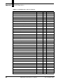
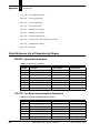
Quick Reference List of Parameters by Region E–2
002-027—Operation Parameters E-2
100-173—1xx Serial Communication Parameters E-2
200-273—BIN x Decoding Group Parameters E-4
400-404—Starnode Setup Parameters E-5
501-560—Inputs/Outputs Parameters E-5
600-639—User Program Parameters E-6
640-668—Ethernet Parameters E-6
670-697—TCP/IP Port Parameters E-7
700-706—Tracking Parameters E-7
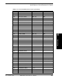
002 - 027 Decoding & Operation Parameters E–8
002
003
006
007
011
012
013
027
OPERATION MODE E-8
IO MODE E-9
DEBUG DATA E-10
DEBUG DATA PORT E-11
NO READ CHAR E-12
LABEL SEPARATOR E-13
MULTI READ CHAR E-14
TUNNEL MULTI READS E-15
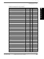
100-173 Serial Communications Parameters E–16
100
120
140
160
101
121
141
161
102
122
142
162
103
123
143
163
104
124
144
164
105
125
145
165
106
126
146
166
107
127
147
167
Rev A, January 2002
BAUD RATE HOST
BAUD RATE TERM
BAUD RATE SETUP
BAUD RATE D-PORT E-16
DATA BITS HOST
DATA BITS TERM
DATA BITS SETUP
DATA BITS D-PORT E-17
PARITY HOST
PARITY TERM
PARITY SETUP
PARITY D-PORT E-18
STOP BITS HOST
STOP BITS TERM
STOP BITS SETUP
STOP BITS D-PORT E-19
FLOW CONTROL HOST
FLOW CONTROL TERM
FLOW CONTROL SETUP
FLOW CONTROL D-PORT E-20
IN PRE. HOST
IN PRE. TERM
IN PRE. SETUP
IN PRE. D-PORT E-21
IN SUF. HOST
IN SUF. TERM
IN SUF. SETUP
IN SUF. D-PORT E-22
OUT PRE. HOST
OUT PRE. TERM
OUT PRE. SETUP
OUT PRE. D-PORT E-23
MHI-2000 Technical Reference Manual
xi
Contents
108
128
148
168
109
129
149
169
110
130
150
170
111
131
171
112
132
172
113
133
173
OUT SUF. 1 HOST
OUT SUF. 1 TERM
OUT SUF. 1 SETUP
OUT SUF. 1 D-PORT E-24
OUT SUF. 2 HOST
OUT SUF. 2 TERM
OUT SUF. 2 SETUP
OUT SUF. 2 D-PORT E-25
ERROR HOST
ERROR TERM
ERROR SETUP
ERROR D-PORT E-26
PROTOCOL HOST
PROTOCOL TERM
PROTOCOL DPORT E-27
PROTOCOL ADDR HOST
PROTOCOL ADDR TERM
PROTOCOL ADDR DPORT E-29
HARDWARE OPTS HOST
HARDWARE OPTS TERM
HARDWARE OPTS DPORT E-30
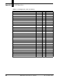
200-274 BIN x Decoding Group Parameters E–31
200
210
220
230
240
250
260
270
201
211
221
231
241
251
261
271
202
212
222
232
242
252
262
272
203
213
223
233
243
253
263
273
204
214
224
xii
BIN 1 SYMBOLOGY
BIN 2 SYMBOLOGY
BIN 3 SYMBOLOGY
BIN 4 SYMBOLOGY
BIN 5 SYMBOLOGY
BIN 6 SYMBOLOGY
BIN 7 SYMBOLOGY
BIN 8 SYMBOLOGY E-31
BIN 1 MIN LENGTH
BIN 2 MIN LENGTH
BIN 3 MIN LENGTH
BIN 4 MIN LENGTH
BIN 5 MIN LENGTH
BIN 6 MIN LENGTH
BIN 7 MIN LENGTH
BIN 8 MIN LENGTH E-32
BIN 1 MAX LENGTH
BIN 2 MAX LENGTH
BIN 3 MAX LENGTH
BIN 4 MAX LENGTH
BIN 5 MAX LENGTH
BIN 6 MAX LENGTH
BIN 7 MAX LENGTH
BIN 8 MAX LENGTH E-33
BIN 1 CHAR POS
BIN 2 CHAR POS
BIN 3 CHAR POS
BIN 4 CHAR POS
BIN 5 CHAR POS
BIN 6 CHAR POS
BIN 7 CHAR POS
BIN 8 CHAR POS E-34
BIN 1 CHAR CHECK
BIN 2 CHAR CHECK
BIN 3 CHAR CHECK
MHI-2000 Technical Reference Manual
Rev A, January 2002
Contents
234
244
254
264
274
BIN 4 CHAR CHECK
BIN 5 CHAR CHECK
BIN 6 CHAR CHECK
BIN 7 CHAR CHECK
BIN 8 CHAR CHECK E-35
400 - 404 Starnode Setup Parameters
400
401
402
403
404
E–36
STARNODE PROTOCOL E-36
TERM. NUMBER E-37
TERM. TYPE E-38
MSG CHAR PREFIX
MSG CHAR SUFFIX E-39
501 - 560 Inputs/Outputs Parameters E–40
501 TRANSMIT DATA E-40
503 INZONE TRIGGER
504 OUTZONE TRIGGER E-41
505 ZONE ERROR CHAR 1
506 ZONE ERROR CHAR 2 E-42
510 INZONE DEBOUNCE (Input 1)
511 OUTZONE DEBOUNCE (Input 2)
512 INPUTS DEBOUNCE (Inputs 3 - 8) E-43
520-524 INPUT (4-8) TRIGGER E-44
553-560 RELAY X HOLD TIME E-45
600 - 639 User Program Parameters
E–46
600 USER STACK SIZE E-46
601 FILE SYSTEM SIZE E-47
602 PROGRAM CONTROL E-48
610-625 USER VARIABLE x E-49
630-639 USER STRING x E-50
640 - 697 Ethernet Network Parameters E–51
640
650
641
651
642
652
643
653
645
655
646
656
647
657
660
661
662
663
664
665
666
667
668
Rev A, January 2002
NETWORK NAME 1
NETWORK NAME 2 E-51
IP ADDRESS 1
IP ADDRESS 2 E-52
SUBNET MASK 1
SUBNET MASK 2 E-53
GATEWAY 1
GATEWAY 2 E-54
BROADCAST 1
BROADCAST 2 E-55
CONTROLLER OPTS 1
CONTROLLER OPTS 2 E-56
HARDWARE ADDRESS 1
HARDWARE ADDRESS 2 E-57
FTP IP ADDRESS E-58
FTP LOGIN NAME
FTP LOGIN PASSWORD E-59
NETWORK LOGIN NAME
NETWORK LOGIN PASSWORD E-60
TELNET LOCAL OPTS E-61
NAME BROADCAST PORT E-62
TCP/IP KEEP ALIVE E-63
TCP/IP CONNECT TIME E-64
MHI-2000 Technical Reference Manual
xiii
Contents
670
680
690
671
681
691
672
682
692
673
683
693
674
675
684
685
694
695
676
686
696
677
687
697
NET 1 DEST IP
NET 2 DEST IP
NET 3 DEST IP E-65
NET 1 LOCAL SOURCE
NET 2 LOCAL SOURCE
NET 3 LOCAL SOURCE E-66
NET 1 PORT
NET 2 PORT
NET 3 PORT E-67
NET 1 PROTOCOL
NET 2 PROTOCOL
NET 3 PROTOCOL E-68
NET 1 MSG PREFIX
NET 1 MSG SUFFIX
NET 2 MSG PREFIX
NET 2 MSG SUFFIX
NET 3 MSG PREFIX
NET 3 MSG SUFFIX E-69
NET 1 MSG CHAR
NET 2 MSG CHAR
NET 3 MSG CHAR E-70
NET 1 OPTIONS
NET 2 OPTIONS
NET 3 OPTIONS E-71
700 - 706 Tracking Parameters
700
701
702
703
704
705
706
Index
xiv
E–72
TRACKING E-75
MILS/TIC E-76
FIXED CONV SPEED E-77
BOX TOLERANCE E-78
FIXED BOX LENGTH E-79
INZONE TO DATA
OUTZONE TO DATA E-80
Index–1
MHI-2000 Technical Reference Manual
Rev A, January 2002
Preface
Welcome
PREFACE
Congratulations on your purchase of the MHI-2000 Programmable Interface. Our goal at SICK
Auto Ident, Inc. is to provide you with a reader/control system of the highest quality that is both
powerful and easy to use. We are also committed to providing you with excellent technical and
customer support services necessary to meet your business needs. We’re glad to have you as a
customer and we’re sure you’ll be pleased with your purchase.
How To Use This Manual
The purpose of this manual is to ensure that your MHI-2000 system becomes operational quickly
and reliably. This manual covers installation, basic operations, including instructions to operate the
MHI-2000 system, and supporting information.
Guide Conventions
The following typographical conventions are used throughout this manual.
•
Items emphasizing important information are italicized or bolded.
•
Keyboard entries are indicated as an italic.
•
Menu selections, menu items, tab selections, and entries in screen image windows are
indicated as such: File, Data Matrix, Options.
Note: Provides useful information about the current topic.
Caution: Provides information for the prevention of damage to the product.
WARNING! PROVIDES INFORMATION FOR THE PREVENTION OF PERSONAL
INJURY OR DAMAGE TO THE PRODUCT.
Rev A, January 2002
MHI-2000 Technical Reference Manual
xv
Preface
Warning Symbols
Class 2 Laser Product
Laser Classe 2
Klasse 2 laserscanner
Laser Klasse 2 Produkt
Producto Láser Clase 2
Luokan 2 laserlaite
Apparecchiatura laser di classe 2
Laser Radiation - Do not stare into Beam.
Rayonnement Laser - Ne pas s’exposer.
Radiación Láser - No mirar fijamente a el rayo.
Laser straling - Niet in straal kijken.
Laserstrahlung - Nicht in den Strahl blicken, auch nicht mit optischen Instrumenten.
Lasersäde - Alä katso valolähteeseen.
Radiazioni laser - Non rivolgere lo sguardo direttamente al raggio laser.
Caution - Laser radiation when open and interlock defeated. AVOID EXPOSURE TO BEAM.
Attention - En cas d’ouverture, risque de rayonnement laser. NE PAS S’EXPOSER.
Peligro - Radiación Láser al abrir. EVITAR LA EXPOSICIÓN DEL RAYO.
Waarschuwing - Bestraling mogelijk bij geopend en ontgrendeld toestel. BLOOTSTELLING AAN LASERSTRAAL
VERMIJDEN!
Vorsicht! Laserstrahlung wenn Abdeckung geöffnet oder Sicherheitsschalter überbrückt. NICHT IN DEN STRAHL
BLICKEN.
Varoitus - Lasersäteilyä saattaa esiintyä avattaessa kotelo ja ohitettaassa suojakytkimet. VÄLTÄ ALTISTUMISTA
LASERSÄTEILYYN.
Attenzione - Radiazioni laser in caso di apparecchiatura aperta e dispositivo di protezione difettoso. EVITARE OGNI
ESPOSIZIONE AL RAGGIO LASER.
Warning - Shock hazard
Danger - Haute tension
Atención - Peligro de descarge
Waarschuwing - Schokgevaar
Warnung! Vorsicht Hochspannung
Sähköiskun vaara
Attenzione - Pericolo di scossa elettrica
Caution
Attention
Peligro
Waarschuwing
Vorsicht
Varoitus
Attenzione
xvi
MHI-2000 Technical Reference Manual
Rev A, January 2002
Preface
Getting Assistance
We hope this manual will be helpful. If you have questions or comments, please don’t hesitate to
contact SICK Auto Ident, Inc. For additional assistance, please refer to the following information.
SICK Auto Ident, Inc. Customer Service Policy
We care about your productivity and will go to great lengths to ensure that you have maximum uptime. Whether you call for a site survey, place an order, or request technical support, you are
assured of prompt, courteous, and personalized attention.
Our state-of-the-art accounting and computer management systems permit us to instantly access
customer order information. A trained staff member is available to assist you with:
•
Order entry assistance
•
Product information and application answers
•
Product delivery status
•
Technical support
•
One-on-one problem resolution
Contact your sales representative. Or, to reach SICK Auto Ident, Inc. Customer Service directly,
call 1-888-264-4641. The fax number is (781) 828-3150.
Return-to-Factory Instructions
Should your MHI-2000 system fail to operate correctly, verify the following:
•
Confirm that it has been properly configured with the proper setup parameters, as ordered.
•
Inspect and verify all cable connections.
If a problem persists, contact your sales representative or SICK Auto Ident, Inc. Customer Service
by calling the numbers provided in “SICK Auto Ident, Inc. Customer Service Policy”.
Please call SICK Auto Ident, Inc. at 1-888-264-4641 to return an MHI-2000 for repair. Request the
Return Authorization (R.A.) Department. Please be prepared to furnish the following information:
•
Company name, address, and telephone number
•
Contact name
•
Return address (if different) and other pertinent shipping information
•
Catalog number and serial number
•
Description of the problem
•
Purchase order and other invoicing information relative to the repair
Rev A, January 2002
MHI-2000 Technical Reference Manual
xvii
Preface
SICK Auto Ident, Inc. will provide you an R.A. number. Please include this R.A. number on the
shipping label and any correspondence concerning the return. Please include several sample
barcode labels, a listing of setup parameters and a detailed description of the problem. Repair or
upgrade estimates shall be furnished upon request.
Upon receiving a defective product with a valid Return Authorization number, SICK Auto Ident,
Inc. will attempt to return the repaired or replacement equipment on a best-effort basis within five
working days. You may have a different support plan specifying other terms.
For critical applications, SICK Auto Ident, Inc. recommends you keep a spare MHI-2000 on hand
for immediate replacement. Alternatively, you can select a support plan that specifies a quick
response time or a MHI-2000 swap.
SICK Auto Ident, Inc. shall pay surface transportation charges for the return shipment if the address
is within the 48 contiguous states or the District of Columbia. Customers outside this area shall pay
shipping costs, customs clearance, and any other related charges.
Your MHI-2000 will be returned after inspection and repair. However, upon return, the MHI-2000
may require re-configuration to the setup parameter values you were using.
Product Warranty
SICK Auto Ident, Inc. guarantees that its products are free from defects in materials or
workmanship (under proper and normal use and maintenance) in accordance with SICK Auto
Ident, Inc.'s operating instructions for a period of one year from the shipping date.
This warranty shall be null and void if equipment is modified, if it is improperly installed or used, if
it is damaged by accident or neglect, or if components are improperly installed or replaced by the
buyer.
Under no circumstances shall SICK Auto Ident, Inc. be liable to the buyer or any other party for
lost profits, diminution of good will, or other special or consequential damages whatsoever.
The warranty appearing here supersedes all other warranties, express or implied, statutory or
otherwise, including any implied warranty of merchantability or fitness for a particular purpose.
xviii
MHI-2000 Technical Reference Manual
Rev A, January 2002
1
Overview &
Maintenance
1
Overview & Maintenance
CHAPTER 1
This chapter provides you with an overview of, and specifications and maintenance for, the
MHI-2000.
Overview
Typical Physical Setup
The MHI-2000 may be used with other equipment, such as photoeyes and a tachometer.
Keysheet
The Keysheet specifies the details of your MHI-2000 setup. It is based on information you
provided to SICK Auto Ident, Inc. about your MHI-2000 application.
The information in the Keysheet customizes the MHI-2000 hardware and software setup for your
site. Do not deviate from the Keysheet or otherwise change the configuration without consulting
SICK Auto Ident, Inc.
Software Updates
Software updates from SICK Auto Ident, Inc. can include changes and improvements in the
following:
•
Operating System
•
Code for Gap Tracking
•
Network
•
File Memory
•
C code
SICK Auto Ident, Inc. will provide software to you, as your application requires. These updates can
be uploaded into your MHI-2000 from your PC, with the software available from SICK Auto Ident,
Inc. on a diskette. The MHI-2000 uses flash memory to allow complete re-programming in the
field.
Rev A, January 2002
MHI-2000 Technical Reference Manual
1-1
Chapter
1
Overview & Maintenance
Specifications
MHI-2000
Configuration
Memory
•
2M (approx. 800K for user C programs and data)
Network
•
Starnode
•
Ethernet 10 base T
•
Additional Ethernet 10 base T (optional)
Optional Solid-State Input/Output Modules
Two optically isolated Opto-22 style modules may be installed as inputs or outputs. They are
controlled by standard input/output signals.
•
IDC15 Type-DC Input (10-32 VDC)
•
ODC15 Type-DC Output (5-60 VDC)
•
IAC15 Type-AC Input (90-140 VAC)
•
OAC15 Type-AC Output (90-140 VAC)
•
IAC15A Type-AC Input (180-280 VAC)
•
OAC15A Type-AC Output (180-280 VAC)
Optional Programmable Interface Controller
For some special applications, an additional PIC board may be installed.
Physical
For mechanical drawings with dimensions, refer to Appendix C, “Dimension Diagrams”.
MHI-2000
•
10.75 x 6.5 x 5 inches (273 x 165.1 x 127 mm)
•
5.5 pounds (2.5 kilograms)
Power
1-2
•
Input—115/230 +/-10% VAC @ 2.0/1.0 A, 50/60 Hz
•
Output - DC power—+12 VDC, 750 mA to photocells, tachometer, etc. +5 VDC, 375 mA to
tachometer
MHI-2000 Technical Reference Manual
Rev A, January 2002
Construction
A single integrated package consisting of an aluminum enclosure, fully gasketed, and mounted on a
1/2 inch (12.7 mm) aluminum base plate.
Environmental
•
Dust-tight and drip-proof
•
Operating Temperature—32° to 122° F (0° to 50° C)
•
Humidity—5% to 95% non-condensing
LED Status Indicators
Ten LEDs on a single display monitor operations and communications.
Communications
There are six independent communications ports:
•
1 asynchronous serial Host port (RS-232) I/O connector
•
1 asynchronous serial Terminal/Slave port (RS-232)
•
1 asynchronous serial Setup port (RS-232)
•
1 asynchronous serial D-port (RS-232)
•
1 RS-485 LAN port with Starnode protocol
•
1 Ethernet port (10 base T)
Inputs
Eight total, active low when <1.0 VDC.
•
Maximum input 30 VDC intermittent, 27 VDC continuous
Outputs
Eight total, open collector solid state—30 VDC at 150 mA, max.
Rev A, January 2002
MHI-2000 Technical Reference Manual
1-3
1
Overview &
Maintenance
Specifications
Chapter
1
Overview & Maintenance
Maintenance
The MHI-2000 requires no special maintenance when operated in an environment free from
extremes of temperature, humidity, shock, and vibration. Perform the following tasks once a month
to keep the MHI-2000 clean and to inspect it for mechanical damage.
1.
Switch MHI-2000 main power OFF before cleaning it.
2.
Clean dirt and dust from the MHI-2000’s LED display, using a soft, lint-free cloth and a nonabrasive liquid cleaner. DO NOT use an abrasive cleaner.
3.
Check all cables for signs of abrasion.
4.
Check that all cable connections are secure.
Caution: The MHI-2000’s internal components do NOT require maintenance. Opening the
MHI-2000 with power applied can expose you to electrical and mechanical hazards, which
can cause bodily injury.
1-4
MHI-2000 Technical Reference Manual
Rev A, January 2002
2
Installation & Setup
CHAPTER 2
This chapter provides you with an overview of the MHI-2000 hardware installation and setup. It
also describes interconnections for the interface terminal board.
Unpacking & Inspection
Unpack the MHI-2000 and any accessories ordered. Depending on what you ordered, the
equipment may have been shipped in more than one carton.
Remove the packing list from the pocket on each carton. Verify that you have received all of the
items shown on the packing list.
Inspect the equipment for shipping damage and, if any exists, notify both the carrier and SICK
Auto Ident, Inc. immediately.
Store the original packing material inside each carton, and store the cartons in a safe place. If the
MHI-2000 or any accessories need to be repaired, upgraded, or modified in the future, return them
to SICK Auto Ident, Inc. in the original cartons with the original packing material.
Refer to “Product Warranty” on page xix and “Return-to-Factory Instructions” on page xviii for
more information.
Installation Checklist
•
Plan and schedule complete installation.
•
Identify and include personnel responsible for:
•
Rev A, January 2002
–
Data system
–
Control or conveyor system
–
Maintenance
–
Installation
Review plan with SICK Auto Ident, Inc. Field Service Engineer—Confirm schedule two
weeks prior to engineer arriving on site for functional checkout.
MHI-2000 Technical Reference Manual
2-1
Installation & Setup
2
Chapter
2
Installation & Setup
Site Preparation
Refer to the Keysheet.
•
AC power to MHI-2000. Ensure AC power is connected to an earth ground.
•
AC power (convenience outlets) for local PC, CRT, modem, oscilloscope. Ensure AC power is
connected to an earth ground.
•
Setup/Diagnostic Terminal—Local CRT, or PC running serial communications software
program, i.e., Microsoft Windows HyperTerminal, ProComm, or Telix.
Electrical Connections
To MHI-2000
•
Grounded, AC power
•
Network (if used)
•
Presence photoeyes
•
Tachometer (installer provides cable)
•
Height-sensing photoeyes
•
Communication cable(s) provided by installer
•
Any special digital I/O connections
•
Modem and cables, provided by installer
Site Preparation
Power
115/230 VAC line power must be brought to the MHI-2000. You should also provide additional 115
VAC outlets for setup and diagnostic test equipment.
Setup
You should have one of the following:
•
PC with terminal emulation software and cable
•
RS-232 ASCII terminal
Communications wiring to the host is necessary.
Photoeyes & Tachometer Installation
Follow the installation directions only if your system requires presence photoeyes, height-detecting
photoeyes, and a tachometer.
2-2
MHI-2000 Technical Reference Manual
Rev A, January 2002
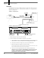
Site Preparation
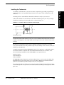
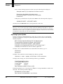
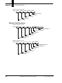
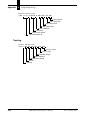
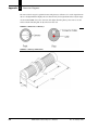
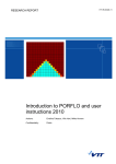
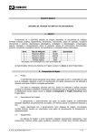
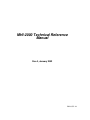
Installing the Tachometer
You must provide a custom bracket to mount the tachometer securely to your conveyor.
Connect the tachometer to a driven roller or other driven rotational part of your conveyor using a
flexible shaft coupling or a belt and pulley drive, as shown in Figure 2–1.
FIGURE 2–1.
Tachometer Driver by Flexible Shaft Coupling
Tachometer Housing
Shaft Coupling
Note: You must use an appropriate flexible shaft coupling or belt and pulley drive to provide
mechanical isolation of the tachometer from your conveyor. Without such isolation, the tachometer
is subject to misalignment, roller shaft wobble, and consequent wear to the tachometer's precision
bearings.
Alternatively, a friction wheel can be used to couple the tachometer to the surface of a belted
conveyor. Friction drives have the potential to slip and cause tracking errors over time, but may be
suitable for your application.
A suitable measuring wheel (P/N 16002070215) with a 12” circumference, a white rubber surface,
and an inside diameter compatible with the standard SICK Auto Ident, Inc. tachometer, and a
universal tracking mounting base (P/N 14005750000), can be purchased from:
Danaher Controls
1675 Delany Road
Gurnee, IL 60031
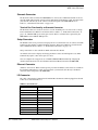
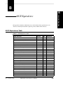
The MHI-2000 requires inputs from a tachometer that produces a conveyor travel resolution finer
than 0.20 inches per pulse with a pulse rate of no more than 1 kHz. Lower resolution will affect
position accuracy but may provide enough accuracy for your application.
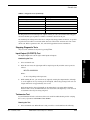
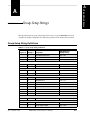
The examples in Table 2–1 display conveyor travel per pulse if a 300-pulses/revolution tachometer
is driven directly from conveyor rollers of the diameters indicated. The speeds listed produce 1 kHz
pulse rates.
Rev A, January 2002
MHI-2000 Technical Reference Manual
2-3
2
Installation & Setup
A tachometer, which measures conveyor movement, is required for gap tracking. Gap tracking is
required when there is the possibility that more than one box may be in the scanning zone at the
same time.
Chapter
2
Installation & Setup
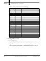
TABLE 2–1. Conveyor
Travel per Pulse
Roller diameter:
2 inches
3 inches
4 inches
Resolution:
0.021 inches
0.031 inches
0.042 inches
Conveyer Speed:
21 inches/sec
105 ft/min
31 inches/sec
157 ft/min
42 inches/sec
210 ft/min
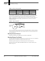
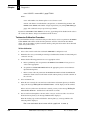
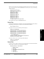
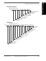
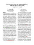
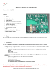
If you use higher conveyor speeds, connect the tachometer directly to a larger diameter driven
roller, or use a belt and pulley system to achieve slower tachometer rotation, as shown in
Figure 2–2. Optionally, use a tachometer that generates fewer pulses per revolution. Figure 2–2
displays a pulley arrangement providing a speed reduction of 3 to 1 and a 33% decrease in
tachometer resolution.
FIGURE 2–2.
Pully Arrangement
Conveyor
Conveyor
Roller
1”Dia.
3”Dia.
Tach
Drive
Pulley
The speed reduction will be proportional to the ratio of the pulley diameters, with the tachometer
connected to the larger diameter pulley. The resolution will decrease in inverse proportion to the
ratio of the diameters.
Mounting Presence Photoeyes
The photoeye positions for your application are specified on your Keysheet.
Mounting Photoeye Tree Bracket
The bracket supports the height-detecting photoeyes on one side of the conveyor. A second bracket
supports reflectors for each photoeye on the other side of the conveyor.
Mount the height-detecting photoeyes immediately upstream of the inzone photoeye.
Dimensions of the bracket available from SICK Auto Ident, Inc. are listed in “Photoeye Tree
Bracket” on page C-3.
2-4
MHI-2000 Technical Reference Manual
Rev A, January 2002
3
Controls, Connectors, & Indicators
CHAPTER 3
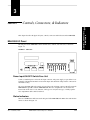
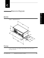
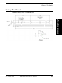
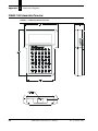
This chapter describes the physical layout, controls, connectors and indicators on the MHI-2000.
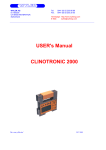
MHI-2000 I/O Panel
The I/O panel on the MHI-2000 contains all indicators, controls, and connectors, as shown in
Figure 3–1.
FIGURE 3–1.
I/O Panel
Power Input/ON-OFF Switch/Fuse Unit
Connect a standard power cord to the AC input connector. The power supply accepts either 115 or
230 VAC, with internal automatic selection. The input cable should be clamped to the connector for
maximum security.
The power ON/OFF (I/0) rocker switch is located above the AC input connector. Press I to turn the
MHI-2000 ON; press 0 to turn the MHI-2000 OFF. The fuse compartment is located above the
Power Switch. The fuse is a 3A, 250 VAC, 3AG type. To verify the fuse type, carefully open the
fuse compartment with a small screwdriver.
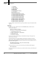
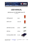
Status Indicators
There are 10 LED status indicators on the I/O panel of the MHI-2000. The LED colors and function
names are shown in Figure 3–2.
Rev A, January 2002
MHI-2000 Technical Reference Manual
3-1
Controls, Connectors,
& Indicators
3
Chapter
3
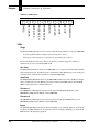
Controls, Connectors, & Indicators
FIGURE 3–2.
LED Display
Yellow
Yellow
Yellow
Yellow
Yellow
Green
INPUTS
OUTPUTS
DECODE
SET-UP
POWER ON
REC DATA
Green
PRESENCE 2
DIAGS.
Yellow
PRESENCE 1
Green
XMIT DATA
Red
LEDs
Diags
The DIAGS. LED lights whenever one or more of the following conditions occur in the MHI-2000:
•
A serious problem with the computer system memory has occurred.
•
Other types of fatal errors have occurred that are detectable by the software.
Because the diagnostics indicator is shared, you may have to run the diagnostics software to
determine the precise reason that the LED is ON.
Rec Data
The REC DATA LED blinks whenever the MHI-2000 receives characters from the Host, Terminal,
Setup and Starnode ports. The Ethernet port is not monitored. This LED helps to verify wiring and
assure that those communication signals are reaching the MHI-2000.
Xmit Data
The XMIT DATA LED blinks whenever the MHI-2000 transmits characters to the Host, Terminal,
Setup, and Starnode ports. The Ethernet port is not monitored. This LED indicates that the MHI2000 is sending data from a communication port.
Presence 1
The PRESENCE 1 LED displays the status of the signal from the INZONE photoeye. The
PRESENCE 1 LED monitors INPUT 1 of the MHI-2000.
Presence 2
The PRESENCE 2 LED displays the status of the signal from the OUTZONE photoeye. The
PRESENCE 2 LED monitors INPUT 2 of the MHI-2000.
Inputs
The INPUTS LED displays the state of all standard inputs (1 - 8) combined. When any of the inputs
is enabled, the LED will light. To determine the status of each input individually, you must run the
INPUTS test of the diagnostics program.
3-2
MHI-2000 Technical Reference Manual
Rev A, January 2002
MHI-2000 I/O Panel
When OPTO-22 relays are installed in the Interface Board, you can determine which input relays
are active by observing the LED associated with each relay.
The inputs on the optional Programmable Interface Controller are not monitored.
Outputs
When output relays are installed in the Interface Board, you can determine which output relays are
active by observing the LED associated with each relay.
Decode
The DECODE LED has no function currently.
Set-Up
The SET-UP LED indicates that the MHI-2000 is in either the Setup or Diagnostics mode.
Therefore, it is not running your custom application software.
Power On
The POWER ON LED indicates that MHI-2000 power is ON. When power is applied, the
computer performs internal diagnostic tests.
Interface Board Connections
The Interface Board is accessible by removing the MHI-2000 cover. The MHI-2000 Command and
Control Board provides 12VDC and 5VDC power to operate the Interface Board.
There are two jumpers, internal to the MHI-2000, to connect DC output power to the interface
board. This is done by moving shunts of JH10 (1-2) and JH11 (1-2) on the Command and Control
Board. This is the default setting.
All control and communication I/O connections, except to networks, should be made at the
Interface Board.
Connect network cables, if used, directly to the MHI-2000. You can also connect a terminal to the
SETUP connector on the front panel of the MHI-2000, although, normally, it will be more
convenient to make the connection at the Interface Board.
Rev A, January 2002
MHI-2000 Technical Reference Manual
3-3
3
Controls, Connectors,
& Indicators
The OUTPUTS LED displays the state of all outputs (1 - 8) combined. When any of the outputs is
enabled, the LED will light. To determine the status of each output individually, you must run the
OUTPUTS test of the diagnostics program.
Chapter
3
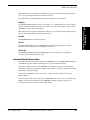
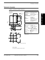
Controls, Connectors, & Indicators
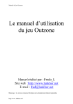
FIGURE 3–3.
3-4
Standard Interface Unit Circuit Board
MHI-2000 Technical Reference Manual
Rev A, January 2002
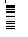
MHI-2000 I/O Panel
Board I/O Connections
TB1-1
GND
GROUND
TB1-2
IN1
INPUT 1
TB1-3
+12V
+12V POWER
TB1-4
GND
GROUND
TB1-5
OUT1
OUTPUT 1
TB1-6
+5V
+5V POWER
TB2-1
GND
GROUND
TB2-2
IN2
INPUT 2
TB2-3
+12V
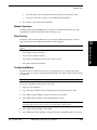
+12V POWER
TB2-4
GND
GROUND
TB2-5
OUT2
OUTPUT 2
TB2-6
+5V
+5V POWER
TB3-1
GND
GROUND
TB3-2
IN3
INPUT 3
TB3-3
+12V
+12V POWER
TB3-4
GND
GROUND
TB3-5
OUT3
OUTPUT 3
TB3-6
+5V
+5V POWER
TB4-1
GND
GROUND
TB4-2
IN4
INPUT 4
TB4-3
+12V
+12V POWER
TB4-4
GND
GROUND
TB4-5
OUT4
OUTPUT 4
TB4-6
+5V
+5V POWER
TB5-1
GND
GROUND
TB5-2
IN5
INPUT 5
TB5-3
+12V
+12V POWER
TB5-4
GND
GROUND
TB5-5
OUT5
OUTPUT 5
TB5-6
+5V
+5V POWER
TB6-1
GND
GROUND
TB6-2
IN6
INPUT 6
TB6-3
+12V
+12V POWER
Rev A, January 2002
MHI-2000 Technical Reference Manual
3
Controls, Connectors,
& Indicators
TABLE 3–1. Interface
3-5
Chapter
3
Controls, Connectors, & Indicators
TABLE 3–1. Interface
Board I/O Connections (Continued)
TB6-4
GND
GROUND
TB6-5
OUT6
OUTPUT 6
TB6-6
+5V
+5V POWER
TB7-1
GND
GROUND
TB7-2
IN7
INPUT 7
TB7-3
+12V
+12V POWER
TB7-4
GND
GROUND
TB7-5
OUT7
OUTPUT 7
TB7-6
+5V
+5V POWER
TB8-1
GND
GROUND
TB8-2
IN8
INPUT 8
TB8-3
+12V
+12V POWER
TB8-4
GND
GROUND
TB8-5
OUT8
OUTPUT 8
TB8-6
+5V
+5V POWER
TB14-1
K1-1
K1 OPTO-22 PIN 1
TB14-2
K1-2
K1 OPTO-22 PIN 2
TB14-3
I/O1
K1 OPTO-22 INPUT or OUTPUT
TB15-1
K2-1
K2 OPTO-22 PIN 1
TB15-2
K2-2
K2 OPTO-22 PIN 2
TB15-3
I/O2
K2 OPTO-22 INPUT or OUTPUT
Control Input Connections
Interface Unit Inputs
All eight standard solid-state control input connections to the Interface Board are available at
terminal block TB1 through TB8, as shown in Figure 3–3, “Standard Interface Unit Circuit Board”
on page 3-4.
Connector assignments are listed in Table 3–1, “Interface Board I/O Connections” on page 3-5.
3-6
MHI-2000 Technical Reference Manual
Rev A, January 2002
MHI-2000 I/O Panel
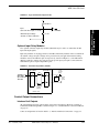
FIGURE 3–4.
Typical Solid-State Input Circuit
+12 VDC
3.3K Ohms
ULN2003
3
0.1 mf
Maximum input voltage
30 VDC, 27 VDC continuous
Optional Input Relay Modules
Two optional solid-state input relay modules (OPTO22) may be used to accommodate AC/DC
input and output signals.
Input relay modules can be plugged into locations K1 or K2. Relay modules with several different
AC and DC voltage and power ratings can be provided to fit your application. External wiring
should be connected to TB14/15 pins 1/2 respectively, as shown in Figure 3–5. An additional 22
AWG is required to complete the connection to the specific input you require. Connect this wire
from TB14/15 pin3 to required input TB1-8 pin2.
FIGURE 3–5.
Solid-State Input Relay Module
TB14,TB15
TB14,TB15
Divert
Control
Relay
K1
Add Wire to
MHI-2000
Specified Input
TB1-TB8
K1 -1
IN_OUT
Divert
Gate
Solid state
input relay
module
(IAC15)
Divert
Gate
Power
K1 -2
Interface Unit
Control Output Connections
Interface Unit Outputs
All eight standard solid-state control output connections to the Interface Board are available at
terminal block TB1 through TB8, as shown in Figure 3–3, “Standard Interface Unit Circuit Board”
on page 3-4.
Connector assignments are listed in Table 3–1, “Interface Board I/O Connections” on page 3-5.
Rev A, January 2002
MHI-2000 Technical Reference Manual
3-7
Controls, Connectors,
& Indicators
Input
active low when input < 1.0 volts
Chapter
3
Controls, Connectors, & Indicators
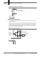
FIGURE 3–6.
Typical Solid-State Output Circuit
Open collector output
limits: 30 Volts at 150 mA max
MHI-2000
Optional Output Relay Modules
Two optional solid-state output relay modules (OPTO22) may be used to accommodate AC/DC
input and output signals.
Output relay modules can be plugged into locations K1 or K2. Relay modules with several different
AC and DC voltage and power ratings can be provided to fit your application. External wiring
should be connected to TB14/15 pins 1/2 respectively, as shown in Figure 3–7. An additional 22
AWG is required to complete the connection to the specific output you require. Connect this wire
from TB14/15 pin3 to required output TB1-8 pin5.
FIGURE 3–7.
Solid-State Output Relay
+12 VDC
TB14,TB15
Line
3.0K
Solid state
Output relay
module
(OAC12)
K1
K1 -1
K1 -2
Hot
Divert Gate
Power
Load Divert
Gate
Neutral
Interface Unit
MHI-2000
3-8
MHI-2000 Technical Reference Manual
Rev A, January 2002
MHI-2000 I/O Panel
FIGURE 3–8.
Open Collector Output Operating an External Relay
+V to match coil requirements
(supplied by user)
1N4003 or
similar diode
TB1-TB8
Relay contacts
to switch load
5
4
To user ground
GND
MHI-2000
MHI-2000
Interface Board
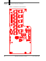
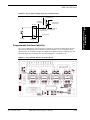
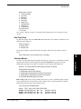
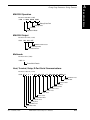
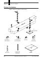
Programmable Interface Controller
Up to seven additional low-voltage DC input or outputs are available at terminal block J2 on an
optional Programmable Interface Controller, as shown in Figure 3–9. Use of the PIC board is
application specific. Definition of input and output pins requires knowledge of PIC function. All
input and output pins are similar to the ones shown in Figure 3–4 and Figure 3–6.
FIGURE 3–9.
Rev A, January 2002
Programmable Interface Controller Board
MHI-2000 Technical Reference Manual
3-9
Controls, Connectors,
& Indicators
3
NOTE: A separate supply is required
for relay coils with voltage ratings
other than 12V.
Output 1
Chapter
3
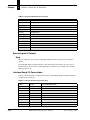
Controls, Connectors, & Indicators
TABLE 3–2. Expansion
Board Input Connections
J2 Marked
Assignment
1 (INZ)
Height Input 1
2 (ANG)
Height Input 2
3 (TACH)
Height Input 3
4 (HT1)
Height Input 4
5 (HT2)
Height Input 5
6 (HT3)
Height Input 6
7 (HT4)
Height Input 7
8 (HT5)
Inzone Presence (connect to TB1-2)
9 +5V
+5V
10 GND
GND
11 CTSOUT
CTSOUT (RS-232)
12 CTSIN
CTSIN (TTL)
Special Inputs & Outputs
Beep
Beep is a solid-state, open-collector output that normally activates an audio tone to signal the
operator.
By default JH1 shunt is positioned from 2-3. This allows the beeper signal to be sent to the on
board transducer. If you wish to send this signal to an external device use TB11 and set the JH1
shunt to positions 1-2.
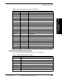
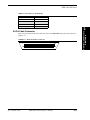
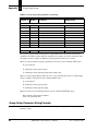
Interface Board I/O Connections
Table 3–3 shows the Interface Unit I/O Connections at Terminal Block TB1. Default assignments
are indicated in parentheses.
TABLE 3–3. Interface
Board Comm Connections
TB9-1
HTXD
HOST TRANSMIT DATA
TB9-2
HRXD
HOST RECEIVE DATA
TB9-3
HDTR
HOST DATA TERMINAL READY
TB9-4
HCTS
HOST CLEAR TO SEND
TB9-5
GND
GROUND
TB10-1
TTXD
TERMINAL TRANSMIT DATA
TB10-2
TRXD
TERMINAL RECEIVE DATA
TB10-3
TDTR
TERMINAL DATA TERMINAL READY
TB9-6
3-10
MHI-2000 Technical Reference Manual
Rev A, January 2002
MHI-2000 I/O Panel
TABLE 3–3. Interface
Board Comm Connections (Continued)
TB10-4
TCTS
TERMINAL CLEAR TO SEND
TB10-5
GND
GROUND
TB11-1
STXD
SETUP TRANSMIT DATA
TB11-2
SRXD
SETUP RECEIVE DATA
TB11-3
GND
GROUND
TB11-4
TERMDET
TERMINAL DETECT
TB11-5
BEEPER
BEEPER
TB11-6
GND
GROUND
TB12-1
TXDD
TRANSMIT DATA D-PORT
TB12-2
RXDD
RECEIVE DATA D-PORT
TB12-3
GND
GROUND
TB12-4
+5V
+5V POWER
TB12-5
EXLASOFF
EXTERNAL LASER OFF
TB12-6
+12V
+12V POWER
TB13-1
T422+
RS-422 TRANSMIT (+)
TB13-2
T422-
RS-422 TRANSMIT (-)
TB13-3
R422+
RS-422 RECEIVE (+)
TB13-4
R422-
RS-422 RECEIVE (-)
TB13-5
GND
GROUND
TB10-6
Controls, Connectors,
& Indicators
3
TB13-6
Expansion Board Input Connections
Table 3–4 shows the Expansion Board Input Connection at Terminal Block J2.
TABLE 3–4. Expansion
Board Input Connections
J2 Marked
Assignment
1 (INZ)
Height Input 1
2 (ANG)
Height Input 2
3 (TACH)
Height Input 3
4 (HT1)
Height Input 4
5 (HT2)
Height Input 5
6 (HT3)
Height Input 6
7 (HT4)
Height Input 7
8 (HT5)
Inzone Presence (connect to TB1-2)
Rev A, January 2002
MHI-2000 Technical Reference Manual
3-11
Chapter
3
Controls, Connectors, & Indicators
TABLE 3–4. Expansion
J2 Marked
Board Input Connections
Assignment
9 +5V
+5V
10 GND
GND
11 CTSOUT
CTSOUT (RS-232)
12 CTSIN
CTSIN (TTL)
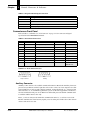
Connectors on Front Panel
Refer to Table 3–5 and Table 3–6, “I/O Connector” on page 3-13 for connector and signal
specification for the MHI-2000 Front Panel.
TABLE 3–5. Front
Pin
Panel Connections
AUXILIARY
1
STARNODE
SETUP
(SETUP/1400)
LAN+ (blue wire)
2
Host RXD
TERM DETECT
Setup TXD
Setup RXD
3
Host TXD
LAN- (white wire)
4
Host DTR
Ground
5
Ground
Frame Ground (cable shield)
6
Ground
Ground
7
8
Host CTS
9
FIGURE 3–10.
6
Ground
Ground
TERM RXD
Setup RXD
TERM TXD
Setup TXD
+5 VDC, 350 mA max
+5 VDC,
350 mA max
Front Panel Connectors
9
9
1
5
6
5
1
Male
Female
Auxiliary
Setup & Starnode
Auxiliary Connector
Auxiliary Connections are also available on TB9 on the Interface Board. The Auxiliary Connector
provides an asynchronous serial I/O port that can be used to connect to a host computer or to other
serial, ASCII devices (such as printer, display terminals, external keyboards, etc.). Control of data
flow, baud rates, etc., is determined by parameters you can set. Refer to Appendix E, “Parameters,”
for more information. This port can use RS-232 or full modem protocols. RS-422 communication
is available with the interface box only.
Pins 2, 3, and 5 are always used for RS-232 communication. Pins 1, 6, 7, and 9 are reserved for
RS-422 communication. Your host may require you to use other pins or make other connections in
order to send and receive data.
3-12
MHI-2000 Technical Reference Manual
Rev A, January 2002
MHI-2000 I/O Panel
Starnode Connector
The Starnode Connector allows the MHI-2000 to be connected to an EIA-485 Starnode local area
network (LAN). This network connection is not implemented in the Interface Unit. You must attach
your network cable directly to the connector on the front panel of the MHI-2000. Refer to
Table 3–5, “Front Panel Connections” on page 3-12.
Terminal Port Functionality on Starnode Connector
Setup Connector
The SETUP connector is provided as an input port for a local terminal. You can connect an ASCII
terminal or a PC running a terminal emulation program. This port uses RS-232 conventions and
runs at 9600 baud. Refer to Table 3–5, “Front Panel Connections” on page 3-12.
Setup connections are also available on TB11 on the Interface Board.
A terminal can be used to display and change parameters values and run diagnostic tests. Most
terminals only require connection to pins 2, 3 and 5.
You can configure the setup port to use a CiMAX 1400 Hand-Held Terminal by changing the
default cable from J10 to J8 on the Command and Control Board, internal to the MHI-2000.
Ethernet Connector
An RJ-45 connector for 10baseT twisted pair is provided. No Ethernet connections are available in
the Standard or Hex Interface Units. You must attach your network cable directly to the RJ-45
connector on the front panel of the MHI-2000.
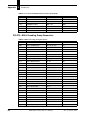
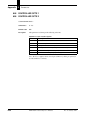
I/O Connector
The cable connecting the Command and Control PCB to the Interface PCB is plugged into the I/O
Connector, as shown in Table 3–6.
TABLE 3–6. I/O
Signal
Connector
Pin #
Output 1
38
Input 1
8
Output 2
14
Input 2
33
Output 3
39
Input 3
9
Output 4
15
Input 4
34
Output 5
40
Input 5
10
Rev A, January 2002
MHI-2000 Technical Reference Manual
3-13
3
Controls, Connectors,
& Indicators
The Starnode Connector can also be used to access the Terminal port so it can be used as a Setup
Port. Terminal Port uses RS-232 conventions. Refer to Table 3–5, “Front Panel Connections” on
page 3-12. CiMAX 1400 is powered by pins 6 and 9. Pin 2 is a terminal detect pin used by the
MHI-2000 to detect CiMAX 1400 presence.
Chapter
3
Controls, Connectors, & Indicators
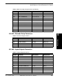
TABLE 3–6. I/O
Signal
3-14
Connector (Continued)
Pin #
Output 6
16
Input 6
35
Output 7
41
Input 7
11
Output 8
17
Input 8
36
RXDD
24
Beep
23
+12V
21
Ground
45
+5V
43
N/C
22
Ground
37
+12V
44
TXDD
25
Host TXD
1
Host RXD
26
Host DTR
2
Host CTS
27
TERM TXD
3
TERM RXD
28
TERM DTR
4
TERM CTS
29
T422+
6
T422-
31
R422+
7
R422-
32
TERM DET
50
Setup TXD
5
Setup RXD
30
+5V
49
Laser Control
47
+5V
48
Ground
20
+5V
18
+12V
46
MHI-2000 Technical Reference Manual
Rev A, January 2002
MHI-2000 I/O Panel
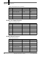
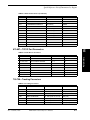
TABLE 3–6. I/O
Connector (Continued)
Pin #
Ground
12
Ground
13
+12V
19
Frame Ground
42
3
50-Pin Cable Connector
This connector plugs into the I/O Connections jack on the MHI-2000 front panel, and is shown in
Figure 3–11.
FIGURE 3–11.
Rev A, January 2002
50 Pin Centronics Connector
1
25
26
50
MHI-2000 Technical Reference Manual
3-15
Controls, Connectors,
& Indicators
Signal
Chapter
3-16
3
Controls, Connectors, & Indicators
MHI-2000 Technical Reference Manual
Rev A, January 2002
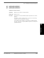
4
Startup & Operation
CHAPTER 4
This chapter describes how to power-up, how to use the Setup port and a terminal to monitor
operation, how to enter the Setup and Diagnostic modes, and how to change parameters.
Serial Communications Ports
The MHI-2000 has a separate, dedicated Setup Port. Figure 3–1, “I/O Panel” on page 3-1 shows the
location of the Setup Port. Refer to “Setup Connector” on page 3-13 for connector and pin
assignment information.
The port designated for Setup can be used to monitor operation, to change parameters and to
perform diagnostic tests. Any RS-232 ASCII terminal or PC running terminal software can be
connected to the Setup port. When connected, the terminal becomes the display and keypad for the
MHI-2000. The Starnode port supports a CiMAX 1400 Hand-Held Terminal.
The Host and Terminal ports can also be used to send commands directly to the MHI-2000’s
operating system. This direct transmission bypasses the menu-driven user interface associated with
the Setup port. Direct transmission is useful for remote setup from a host computer. The commands
are described in Chapter 6, “Diagnostics”.
The Starnode port allows the MHI-2000 to be connected to an EIA-485 Starnode Local Area
Network. Most functions that can be performed through the serial ports can also be performed
through the Starnode port.
The MHI-2000 has an Ethernet 10 base T port. Most functions that can be performed through the
serial ports can also be performed through the Ethernet port.
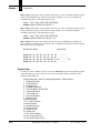
Power Up
When you power up or reset the MHI-2000, the SET-UP LED will flash for a short time. During
this time, the MHI-2000 will send several status messages to the Setup port.
CiMatrix Omni-2000 Bootrom Version x.x
Creation Date: mm dd yyyy, hh:mm:ss
The lines above display the product name, and the Command boot block version and date.
Type '!' to stop auto-boot ...
0
Auto-Booting ...
Rev A, January 2002
MHI-2000 Technical Reference Manual
4-1
Startup & Operation
4
Chapter
4
Startup & Operation
The section above provides a 5 second delay to allow you to change the basic boot parameters. This
is further described after the standard status messages.
-------------------------------------------------* Current Boot Parameters:
*
-------------------------------------------------Boot Device
: xxxxx
Network Device
: xxxxx
Network Device Unit Number
:0
Network Name
: xxxxx
IP Address With Subnet Mask
: x.x.x.x:ffffff00
Gateway IP Address
: x.x.x.x
Boot Option Flags (In Hex)
: 0x0
FTP Server Name
: xxxxxxx
FTP Server IP Address
: x.x.x.x
FTP File Name
: xxxxxx
FTP Login Password
: xxxxxx
FTP Login User Name
: xxxxxx
The lines above display all of the current boot parameter of the MHI-2000.
Loading OS from Flash ... sectors 7-13
Uncompressing xxxxxx bytes ...
Checksum OK.
Starting at address 0x8002000 ...
The section above displays while the Command OS is being copied from flash and run.
(C) 2001 Sick Auto Ident, Inc. ALL RIGHTS RESERVED
MHI-2000 Ver. x.x Build Date: mmm dd yyy, hh:mm:ss
User Program: None (Waiting For Download)
Scanner Setup
On-Board Ethernet: 10.6.1.210
Add-on Ethernet: Not Installed
Operation Mode: Idle
Tracking: Disabled
Host Port: No Protocol
Term Port: No Protocol
Setup Port: No Protocol
D Port: No Protocol
Starnode Port: No Protocol
Tcp Port 1: No Protocol
Tcp Port 2: No Protocol
Tcp Port 3: No Protocol
Ethernet Link(s) Active
If parameter 401 TERM. NUMBER and parameter 402 TERM. TYPE are not equal to 0, one of the
following messages will be displayed, depending on Starnode status:
No Starnode
Starnode is Active, Terminal # xxxx
4-2
MHI-2000 Technical Reference Manual
Rev A, January 2002
Serial Communications Ports
MHI-2000 Setup is also displayed. These refer to parameters 641, 651, 002, 700, 111, 131, 151,
171, 400, 673, 683, and 693 respectively.
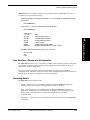
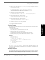
If while countdown is running for auto boot, a <!> is received the following message
will be sent.
[Omni2000 Boot]:
If you enter a ?. the list of commands will be displayed.
[Omni2000 Boot]: ?
- help
- start operating system
- change boot parameters
- display boot parameters
- reboot system
- toggle to debug boot mode
- download and update OS image in Flash
4
Startup & Operation
Commands:
? or help
@ or go
change
display
reboot
toggle
updateos
Available Boot Devices (Names Are Case Sensitive):
xxxxxx unit 0
slip
flash
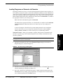
User Interface—Parameters & Diagnostics
The MHI-2000 user interface is accessed using a terminal connected to the Setup Port. This allows
you to change parameters and run diagnostics and calibration procedures. Refer to Chapter 6,
“Diagnostics” for more information.
You can also change parameters without going through the user interface by using Host
Commands. These commands can be sent over any of the communication ports, Host, Terminal, or
Starnode. Refer to Chapter 6, “Diagnostics” for more information.
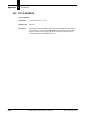
Operating Modes
The MHI-2000 operates in three modes:
•
Normal — In this mode, you can monitor information about the MHI-2000’s operation,
including the barcode read, input and output status, and barcode quality.
•
Setup — In this mode, you can set parameters to program the MHI-2000 for differing
applications, including the type of terminal you are using, the barcode symbology on your
labels, presence configuration, use of output relays, height of boxes, and serial
communications.
•
Diagnostics — In this mode, you can test the hardware and software to check the MHI-2000
performance.
Rev A, January 2002
MHI-2000 Technical Reference Manual
4-3
Chapter
4
Startup & Operation
Normal Mode
In the Normal mode, you can program the MHI-2000 to send information such as label placement,
box size, or bin information.
Refer to parameter 006 DEBUG DATA for a description of the various debug reports available.
Setup & Diagnostic Modes
Special Host commands, ?S and ?D, are used to place the MHI-2000 into the Setup or Diagnostic
mode. These commands are only recognized when received at the Setup Port. Refer to Chapter 6,
“Diagnostics” for more information. Parameter 007 DEBUG DATA PORT defines the ports that
receive setup data (Terminal, Host, Ethernet, Setup).
A beginning and ending message character must frame the command. If parameter 403 MSG
CHAR PREFIX and 404 MSG CHAR SUFFIX have not been changed from their default value of
~ , type the commands:
~?S~ (tilde, question mark, S, tilde) to enter the Setup mode.
~?D~ (tilde, question mark, D, tilde) to enter the Diagnostic mode.
You can also enter the Setup and Diagnostic modes over the Starnode network. The Starndem
program can be used in a rudimentary fashion by manually sending the appropriate messages. To
enter Setup or Diagnostics from Starndem, or any program controlling the Starnode network, send
a ?S or a ?D message to the terminal. It will respond with the first line in the menu.
Use a command of none and begin each message with /M. To exit the menu, send /ME, with the E
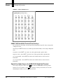
indicating Exit.
You have exited the Setup/Diagnostic mode on the Starnode network when the message EXIT
SETUP or EXIT DIAGNOSTICS is sent from the Starnode port when E is received.
Resetting to Default Parameters
You can return to SICK Auto Ident, Inc. default parameter values at any time by entering the ?R
command through any communication port. If sent through a Host or Terminal port, send the
command as ~?R~ (assuming MSGCHAR is a ~ ), or ?R over a Starnode network, to restore
default parameters.
WARNING! YOUR MHI-2000 MAY USE NON-DEFAULT PARAMETERS
CUSTOMIZED FOR YOUR APPLICATION. THESE PARAMETERS ARE DETAILED
IN YOUR KEYSHEET. RESETTING THE MHI-2000 TO USE DEFAULT PARAMETERS
WILL CAUSE YOUR CUSTOMIZED PARAMETERS TO BE LOST. THEY WILL NEED
TO BE RESTORED.
Non-Intelligent ASCII Terminal
Upon receiving a ~?S~ or ~?D~ command, the MHI-2000 will enter the Setup or Diagnostic mode
and display a corresponding menu on the ASCII terminal. The Setup menu offers a quick, easy way
of viewing and, if necessary, changing parameter values. The Diagnostic menu offers a simple way
to run diagnostic tests.
4-4
MHI-2000 Technical Reference Manual
Rev A, January 2002
Serial Communications Ports
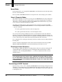
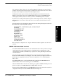
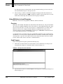
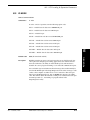
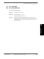
Setup Menu on the ASCII Terminal
The Setup menu displays parameter number, parameter name (in abbreviated form), and current
value. All parameter abbreviations are listed in Appendix E, “Parameters”.
The parameter display format is:
III NNNNNN VVVVVV
Where:
III — The three-digit parameter number
NNNNNN — The abbreviated parameter name
VVVVVV — The value currently stored in memory
SETUP - (P)REVIOUS, (G)OTO, (T)OGGLE, (E)XIT
This line lists all but one of the scrolling options that allow you to view parameters or leave the
Setup menu. The scrolling options function as follows:
•
Enter—Display the NEXT parameter. To view the parameter after the parameter displayed on
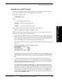
the last line of the screen, if one is currently shown (or parameter 002 OPERATION MODE if
none are shown), press Enter. The next parameter will appear on the next line. If the screen is
full, it will scroll up and delete the top line to make room for the new line.
For example, when Enter is pressed four times after the Setup mode is entered, the display will
appear as:
SETUP - (P)REVIOUS, (G)OTO, (T)OGGLE, (E)XIT
002 OPERATION MODE
0
003 IO MODE
0000
006 DEBUG DATA
00000
007 DEBUG DATA PORT 0000
Continuing to press Enter after the screen is filled will cause succeeding parameters
to be displayed at the bottom of the list, with preceding parameters deleted from the
top.
•
P—Display the PREVIOUS parameter. To view the parameter previous to the parameter
displayed on the last line of the screen, if one is currently shown, press P followed by Enter.
The previous parameter will appear on the next line. If the screen is full, it will scroll up and
delete the top line to make room for the new line.
•
G—GOTO a specific parameter. To GOTO a specific parameter, press G followed by the
three-digit parameter number followed by Enter. The parameter and its current value will be
displayed on the next line of the display. If the display is full, it will scroll up to make room for
the new line. When both a parameter number and a valid value are entered, that parameter’s
old value will be replaced by the newly entered value. For example, entering G00608 will
display parameter 006 DEBUG DATA and enter a value of 08. The change will only become
effective when you EXIT the menu.
Rev A, January 2002
MHI-2000 Technical Reference Manual
4-5
Startup & Operation
4
When you first enter the Setup menu, the following line will be displayed:
Chapter
4
Startup & Operation
•
T—TOGGLE between Diagnostic and Setup menus, without changing parameter position.
That is, if you TOGGLE to the Diagnostic menu and then TOGGLE back to the Setup menu,
you will return to the same parameter that you were viewing before you toggled. To toggle,
press T followed by Enter.
•
E—EXIT the Setup/Diagnostic menu and resume operation. All changes made to parameter
values prior to the EXIT command will become effective upon exiting. To EXIT, press E
followed by Enter.
Note: When exiting the setup/diagnostic menu, if parameter values have been changed, then
the MHI-2000 prompts whether these changes should be saved. Responding yes (Y) will save
the changes.
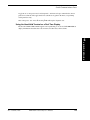
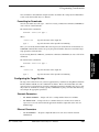
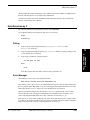
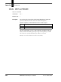
Data Entry Through Setup Menu on the ASCII Terminal
Enter new values as follows.
1.
Move through the Setup menu to display the desired parameter on the last line of the list.
2.
Type in a new value. Press Enter to enter the value.
3.
–
If you entered a valid value, the beeper will sound once and the terminal will show the
parameter again, with the new value replacing the old one.
–
If you entered an invalid value, three short beeps will be sounded. The previous value for
the parameter will remain displayed and unchanged.
Exit the Setup menu to accept the changed value, or move to the next parameter to be changed.
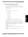
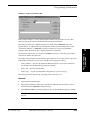
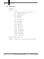
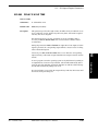
Diagnostics Menu Display on the ASCII Terminal
The Diagnostics menu lists all of the diagnostic tests that are available. Operation is similar to
Setup menu operation. When you enter the menu from the Normal mode, the following will be
displayed:
DIAGNOSTICS - (P)REVIOUS, (R)UN, (T)OGGLE, (E)XIT
If you toggle from the Setup menu to the Diagnostic menu, you will see the above line plus all of
the Diagnostic menu lines you have previously displayed.
While in the Diagnostics menu, your choices are:
4-6
•
Enter—Display NEXT test on the last line.
•
P—Display the PREVIOUS test on the last line.
•
R—RUN the diagnostic test currently displayed on the last line. Refer to the individual test
descriptions described in Chapter 6, “Diagnostics”.
•
T—TOGGLE between the Diagnostics and Setup menus.
•
E—EXIT the Diagnostics menu and return to Normal mode.
MHI-2000 Technical Reference Manual
Rev A, January 2002
Serial Communications Ports
Since parameter changes do not take effect until you EXIT the Setup menu, you cannot change a
parameter in the Setup menu and then toggle to the Diagnostic menu to observe the effect. Instead,
you must exit the Setup menu and then reenter the Diagnostic menu.
The Diagnostic menu wraps around. If you back up through the menu from the first test, IO
PORTS, you will display the last test SYSTEM STATS on the last line. If SYSTEM STATS is
already displayed when you advance forward, you will see IO PORTS again on the last line.
If you have been working with both the Setup menu and the Diagnostic menu, and have changed
parameter values, these changes will become effective upon exiting either the Diagnostic or the
Setup menu.
The following shows how the Diagnostic menu will look after entering the Diagnostic mode from
the Normal mode and pressing Enter repeatedly.
4
Startup & Operation
DIAGNOSTICS - (P)REVIOUS, (R)UN, (T)OGGLE, (E)XIT
IO PORTS
TACHOMETER TEST
TACHOMETER CAL.
KEYSHEETS
OS UPDATE
NETWORK PING
NETWORK STATS
PORT TEST
REAL TIME CLOCK
STARNODE MONITOR
SYSTEM STATS
Refer to Chapter 6, “Diagnostics” for complete information about the diagnostic tests and how to
run them.
CiMAX 1400 Hand-Held Terminal
The CiMAX 1400 Hand-Held Terminal is a full ASCII terminal with a 4 line by 20-character liquid
crystal display. It has a non-volatile memory for custom function key assignments. It accepts
control characters and some (non-ANSI) escape sequences for cursor positioning and other hostcontrolled functions.
The same menu that is used for the ASCII terminal is used for the hand-held terminal (HHT).
Because the CiMAX 1400 has a 4 by 20 display, some of the parameters are displayed on two lines.
Function keys are programmed to provide entry to the Setup mode (~?S~) and the Diagnostic
mode (~?D~).
The CiMAX 1400 requires +5 VDC and Ground. This is supplied by the MHI-2000 when the
CiMAX 1400 is connected to the Starnode port at the MHI-2000.
When the CiMAX 1400 is connected to the Starnode port, it pulls the TERMinal DETect pin on the
port low, to indicate to the MHI-2000 that the CiMAX 1400 is connected.
Disconnecting the CiMAX 1400 reboots the MHI-2000 and restores the system to the master-slave
configuration. The keyboard of the CiMAX 1400 is shown in Figure 4–1.
Rev A, January 2002
MHI-2000 Technical Reference Manual
4-7
Chapter
4
Startup & Operation
FIGURE 4–1.
CiMax 1400 Keyboard
CiMAX 1400 Hand-Held Terminal Function Keys
Two function keys, F1 and F2, on your keyboard are programmed to provide entry to Setup mode
or Diagnostic mode.
You must press SHIFT and release it, and then press the Function Key to enter Setup or Diagnostic
mode.
Setup Mode—Press SHIFT - F1. Sends ~?S~ (tilde, question mark, capital S, tilde).
Diagnostic Mode—Press SHIFT - F2. Sends ~?D~ (tilde, question mark, capital D, tilde).
User Programmable—Press SHIFT- F3. Refer to the CiMAX 1400 User Guide for more
information.
User Programmable—Press SHIFT- F4. Refer to the CiMAX 1400 User Guide for more
information.
Special-Use Alpha Keys on the CiMAX 1400 Hand-Held Terminal
Exits Setup or Diagnostic Mode—Press E . This returns the MHI-2000 to normal operation.
Displays the Previous Menu— Press P . This returns you to the previous menu, or leaves the
Setup/Diagnostic Mode if you are in the topmost menu.
4-8
MHI-2000 Technical Reference Manual
Rev A, January 2002
Serial Communications Ports
Toggles Between Diagnostic Mode and Setup Mode—Pointers are kept to remember the current
position in each menu. The toggle function is available at any point in the menu, except during
actual parameter entry.
Runs a Diagnostic Test—Press R. Pressing Enter will stop the diagnostic test.
Using the Hand-Held Terminal as a Real Time Display
Because the CiMAX 1400 terminal supports cursor positioning, it can be used with MHI-2000s to
display information about barcodes read, I/O status, and other data, all in real time.
Startup & Operation
4
Rev A, January 2002
MHI-2000 Technical Reference Manual
4-9
Chapter
4-10
4
Startup & Operation
MHI-2000 Technical Reference Manual
Rev A, January 2002
5
Host Commands & Downloads
CHAPTER 5
This chapter describes how to use a Starnode network, Ethernet network, and the serial ports to
connect the MHI-2000 to a host computer to communicate with, control, and download C
programs.
Introduction
•
How to control the MHI-2000 or solicit information from it using commands downloaded
from a host computer or Starnode controller.
•
How to change parameters using commands from a host computer.
•
How to develop C programs for a MHI-2000 and download them to it.
Before beginning Starnode operations, you should know the network protocols and messages.
Control Commands from the Host
When sending commands to the MHI-2000 through a:
•
Host or Terminal/Setup port, a framing character, normally a tilde (~), must be sent before and
after each command.
•
Starnode or Ethernet port, a forward slash (/) must precede each command. Otherwise, all
strings that begin with an ASCII A or greater will be interpreted as data and will be sent to the
user program.
In Starnode environments, command values are passed via the SSEND, SBRDC, or SBRDT
operations.
A description of each command is described in Table 5–1. The commands are listed numerically,
by decimal value, in ascending order. Commands with a decimal value less than 65 are processed at
the operating system level. Commands with a decimal value of 65 or greater are interpreted as data
to be passed to a user C program running on the MHI-2000.
Rev A, January 2002
MHI-2000 Technical Reference Manual
5-1
5
Host Commands &
Downloads
You can connect the MHI-2000 to a host PC by a Starnode network via the STARNODE port,
Ethernet network via 10 base T port, or through a serial port. Once communication with the host or
network has been established, you can command the MHI-2000 to perform many functions and to
provide requested information. The commands can be sent to the Setup port, but are most
commonly sent to the Host, Ethernet or Starnode port. This chapter will describe in detail:
Chapter
5
Host Commands & Downloads
TABLE 5–1. Terminal
Control Commands
Command
5-2
Message Type
(Dec/Hex)
(Serial)
(Network)
Request Diagnostic String
52/34
~4~
4
Request Status Information
53/35
~5~
5
Reset
59/3B
~;~
;
Clear Diagnostic Count
60/3C
~<~
<
Enable Digital Output
61/3D
~=x~
=x
Turn Relay Off
62/3E
~>x~
>x
Setup Command
63/3F
~?x~
?x
Upload Parameter
37/25
~%x~
%x
Program Message
65/41 (or greater)
A (or greater)
A (or greater)
Display Box/No Read Count
~TOTAL~
/TOTAL
Outzone Deviation Statistics
~TOLER~
/TOLER
Start Presence
~!~
/!
Stop Presence
~$~
/$
Clear Box/No Read Registers
~TOT00~
/TOT00
MHI-2000 Technical Reference Manual
Rev A, January 2002
Control Commands from the Host
ASCII 4 Command—Requesting a Diagnostic String
When sent over STARNODE or TCP/IP, use this format 4.
When sent serially and the default MESSAGE CHARACTER is ~, use this format ~4~.
Upon receiving an ASCII 4 command (decimal 52; hexadecimal 34), the MHI-2000 will send the
following string back to the controller:
MHI #NNNNN
Where:
NNNNN is the message count for this MHI-2000. This value will be between 00000 and 65535.
This string can be used for diagnostic purposes. The message count is incremented each time this
message is requested. The count is reset to zero when the unit receives an ASCII < command
(decimal 60; hexadecimal 3C), an ASCII ; command (decimal 59; hexadecimal 3B); or when the
MHI-2000 is rebooted by turning it Off and then On again.
Message Format—None
Host Commands &
Downloads
5
Rev A, January 2002
MHI-2000 Technical Reference Manual
5-3
Chapter
5
Host Commands & Downloads
ASCII 5 Command—Requesting Status Information
When sent over STARNODE or TCP/IP, use this format 5.
When sent serially and the default MESSAGE CHARACTER is ~, use this format ~5~.
When the MHI-2000 receives an ASCII 5 command (decimal 53; hexadecimal 35), it responds by
sending a string representing its current status. The information returned can be useful for
troubleshooting malfunctions. The returned string has the format:
MHI VV ABCDEFGHIJKLMNOPQRSTUV
Where:
VV—The version number of the software used in the MHI-2000
ABCDEFGHIJKLMNOPQRSTUV—The 22-character diagnostic string
The diagnostic status string reflects the current status of the MHI-2000, as shown in Table 5–2.
TABLE 5–2. Status
5-4
String Interpretation
Position
Meaning When 1
A
Inzone Status
B
Outzone Status
C
Zone Error Status
D
Decode Status
E
BTL Status
F
Scan Speed Status
G
Transmit Data Status
H
NAK Status
I
Receive Data Status
J
Receive Error Status
K
NO READ Status
L
MATCH Status
M
NO MATCH Status
N
Setup Status
O
Program Status
P
Default Status
Q
Fault Status
R
Conveyor Stalled Status
S
Reverse Tach Status
T
Ethernet Fail Status
U
Starnode Fail Status
V
Slave Offline Status
MHI-2000 Technical Reference Manual
Rev A, January 2002
Control Commands from the Host
Status String Digit Explanations
A—Inzone Status
1 indicates that the presence photoeye or Microswitch™ has detected an object entering the
scanning zone.
B—Outzone Status
1 indicates that the outzone presence photoeye or Microswitch has been triggered. This
indicates that the box or object is leaving the scanning zone.
C—Zone Error Status
1 indicates that a zone synchronization error has occurred. When not using gap tracking, this
error occurs when either the inzone presence detecting device signals a second time before the
outzone detector has signaled once, or the outzone device signals prior to an inzone signal.
D—Decode Status
1 indicates that the decoder is processing data.
1 indicates that the MHI-2000 is falling behind in analyzing data stored in the bar timing logic
(BTL) buffer. This digit may be 1 if large amounts of barcoded data are being scanned.
F—Scan Speed Status
1 indicates that the scanning mirror is not running within the normal operating range.
G—Transmit Data Status
1 indicates that data is currently being sent through the Host, Terminal, or Starnode Ports.
H—NAK Status
1 indicates that the MHI-2000 does not perceive the Starnode network as operational, i.e., the
network has not polled the MHI-2000 recently. It may also indicate an error in data received
from the Starnode Controller.
I—Receive Data Status
1 indicates that the MHI-2000 is currently receiving data through the Host, Setup, or Starnode
Ports.
J—Receive Error Status
1 indicates that received data contained a parity or framing error.
K—NO READ Status
1 indicates a NO READ output energized.
L—MATCH Status
1 indicates a MATCH output energized.
Rev A, January 2002
MHI-2000 Technical Reference Manual
5-5
Host Commands &
Downloads
5
E—BTL Status
Chapter
5
Host Commands & Downloads
M—NO MATCH Status
1 indicates a NO MATCH output energized.
N—Setup Status
1 indicates that the unit is operating in the Diagnostics mode or the Setup mode. Refer to
“Setup & Diagnostic Modes” on page 4-4 for more information.
O—Program Status
1 indicates that the MHI-2000 is currently executing a user program.
P—Default Status
1 indicates that the MHI-2000 is in the Default Setup mode.
Q—Fault Status
1 indicates that there is a hardware error fault somewhere in the system (FAULT LED).
R—Conveyor Stalled Status
1 indicates that the conveyor has stalled.
S—Reverse Tach Status
1 indicates that reverse conveyor movement has been detected.
T—Ethernet Fail Status
1 indicates that the MHI-2000’s network connections are set up and the Ethernet link(s) are
broken.
Note: The entire network must be disabled if the link on just a single controller is broken.
U—Starnode Fail Status
1 indicates that the MHI-2000 is configured for Starnode but there is no Starnode
communication with Starnode Controller.
V—Slave Offline Status
1 indicates that the slave device is offline.
Example
If the default MESSAGE CHARACTER value is not changed, downloading the string ~5~ over
the Host or Setup ports will cause the MHI-2000 to return a diagnostic string.
5-6
MHI-2000 Technical Reference Manual
Rev A, January 2002
Control Commands from the Host
ASCII ; Command—Rebooting MHI-2000
When sent over STARNODE or TCP/IP, use this format ;.
When sent serially and the default MESSAGE CHARACTER is ~, use this format ~;~.
Upon receiving an ASCII ; (semicolon) command (decimal 59; hexadecimal 3B), the MHI-2000
will reboot as if it had been turned Off and then On again. The MHI-2000’s parameter values will
be safely stored in memory after startup.
Message Format—None
Host Commands &
Downloads
5
Rev A, January 2002
MHI-2000 Technical Reference Manual
5-7
Chapter
5
Host Commands & Downloads
ASCII < Command—Clearing Diagnostic Count
When sent over STARNODE or TCP/IP, use this format <.
When sent serially and the default MESSAGE CHARACTER is ~, use this format ~<~.
The ASCII < (less than sign) command (decimal 60; hexadecimal 3C) is used to clear the message
count from a MHI-2000 without having to restart it. Refer to “ASCII 4 Command—Requesting a
Diagnostic String” on page 5-3 for details regarding the message count.
This count may also be reset by sending an ASCII ; command that resets the MHI-2000 to its
default values.
Message Format—None
5-8
MHI-2000 Technical Reference Manual
Rev A, January 2002
Control Commands from the Host
ASCII = Command—Enabling Relay Control Outputs
When sent over STARNODE or TCP/IP, use this format =NNN.
When sent serially and the default MESSAGE CHARACTER is ~, use this format ~=NNN~.
The solid-state control outputs can be enabled by downloading the ASCII = (equal sign; decimal
61; hexadecimal 3D) command.
Message Format— =NNN
Where:
NNN—The output to enable in accordance with the following:
–
001 for output 1
–
002 for output 2
–
004 for output 3
–
008 for output 4
–
016 for output 5
–
032 for output 6
–
064 for output 7
–
128 for output 8
5
Host Commands &
Downloads
•
To enable outputs in combination, enter the sum of the individual output values.
For example, entering 007 will enable the first three outputs. Entering 255 will enable all eight
outputs.
When the RLYHLD (relay hold) time for an output is non-zero, that output will automatically
disable at the end of the hold time. When the RLYHLD is zero, the output will remain enabled.
By sending a 0 as the parameter NNN, it is possible to suspend all relay hold countdowns, so that
the outputs will not switch back to their disabled state).
Example
~=0~ Suspend Relay Hold Countdowns
The current states of the outputs (enabled or disabled) will not be directly affected by sending a 0.
Example
Downloading the string ~=004~ over the Host or Setup port will enable output 3.
Rev A, January 2002
MHI-2000 Technical Reference Manual
5-9
Chapter
5
Host Commands & Downloads
ASCII > Command—De-Energizing Relay Control Outputs
When sent over STARNODE or TCP/IP, use this format >NNN.
When sent serially and the default MESSAGE CHARACTER is ~, use this format ~>NNN~.
The solid-state control outputs can be de-energized by downloading the ASCII > (greater-than sign;
decimal 62; hexadecimal 3E) command.
Message Format—>NNN
Where:
•
NNN—The output to disable in accordance with the following:
–
001 for output 1
–
002 for output 2
–
004 for output 3
–
008 for output 4
–
016 for output 5
–
032 for output 6
–
064 for output 7
–
128 for output 8
To disable outputs in combination, enter the sum of the individual output values.
By sending a single 0 as the parameter NNN, it is possible to resume all relay hold countdowns, so
that the outputs will switch back to their disabled states at the end of their Relay Hold Countdowns.
Example
~>0~ Resume Relay Hold Countdowns
The current states of the outputs, enabled or disabled, will not be directly affected by sending a 0.
Example
Downloading the string ~>004~ over the Host or Setup port will disable output 3.
5-10
MHI-2000 Technical Reference Manual
Rev A, January 2002
Control Commands from the Host
ASCII ? Command—Setup
When sent over STARNODE or TCP/IP, use this format ?x, ?99y, or ?9z.
When sent serially and the default MESSAGE CHARACTER is ~, use this format ~?x~, ~?99y~,
or ~?9z~.
The ASCII ? (question mark; decimal 63; hexadecimal 3F) command tells the MHI-2000 that this
is a Setup command. These allow the network or application running at the host to change or read
the MHI-2000’s parameters, as well as to control the execution of any resident C program running
on the MHI-2000.
Message Format— ?x or
?99y or
?9z
Where:
?—The ASCII character that indicates a setup command.
Specific Control Commands
TABLE 5–3. Special
Control Commands
?S
This command causes the MHI-2000 to enter the Setup Menu. In this menu, you can
view and change any of the MHI-2000 parameters. For more information, see
Chapter 4, “Startup & Operation”.
?D
This command causes the MHI-2000 to enter the Diagnostics Menu. In this menu, you
can run a variety of useful diagnostic tests for alignment and troubleshooting
requirements. For more information, see Chapter 4, “Startup & Operation” and
Chapter 6, “Diagnostics”.
?R
This command causes all of the MHI-2000’s parameters to be set to default values.
Care should be taken when using this command, because there are a few parameters
that are used for hardware and communication requirements. Prior to the use of this
command, you should have stored the keysheet parameters or upload all group
strings to an ASCII file.
?THH:MM:SS,mm-dd-yy
This command is used to set the on-board real-time clock (RTC). If Starnode is
connected, the RTC will be set to the Starnode time, and this command need not be
used. The RTC is backed up by a battery, and it continues to keep time when the
MHI-2000 power is Off. The command can be used over any serial port.
All parameters must be entered as two-digit numbers, using leading zeros where
necessary.
HH = hours, 24-hour format (00 to 23)
MM = minutes
SS = seconds
mm = month
dd = day
yy = year
Rev A, January 2002
MHI-2000 Technical Reference Manual
5-11
5
Host Commands &
Downloads
These are basic commands to perform specific tasks. They follow the format ?x, where x is S, D, R,
or THH:MM:SS,mm-dd-yy.
Chapter
5
Host Commands & Downloads
Uploading Multiple Group Commands
These are your basic group upload commands that will send information to whichever
communication port requested the information. This may be useful for saving specific MHI-2000
parameters to a file, or just to review the MHI-2000 current settings. Appended to the end of this
transmission is ~;~, used to perform a restart of the MHI-2000 if these groups were back
downloaded.
This may be useful when configuring multiple MHI-2000s or transferring one MHI-2000’s setup
configuration to another.
They follow the format ?99y, where y is 7, 8, or 9.
TABLE 5–4. Multiple
Group Commands
?997
This is similar to a setting of 9, with the exception of groups 45, 46, and 47, which are
missing. In the MHI-2000, groups 45, 46, and 47 do not exist. This is the same as a
setting of 9. Each group setup string is uploaded with a ~% prefix for later
downloading use.
?998
This command causes the MHI-2000 to upload current endpoint table. This selection
is not applicable with MHI-2000 devices.
~%890 +000 +000 +000 +000 +000 +000 +000 +000~
~%891 +000 +000 +000 +000 +000 +000 +000 +000~
~%892 +000 +000 +000 +000 +000 +000 +000 +000~
~%893 +000 +000 +000 +000 +000 +000 +000 +000~
~%894 +000 +000 +000 +000 +000 +000 +000 +000~
~%895 -+000 +000 +000 +000 +000 +000 +000 +000~
~%896 200 500~
~;~
?999
This command causes the MHI-2000 to upload all group setup strings. Each group
setup string is uploaded with a ~% prefix for later downloading use. The first group is
shown below. As you can see, each parameter is separated by a <space>. Refer to
Chapter A, “Group Setup Strings” for a description of each group setup string.
~%800 0 0000 00 0500 00000 0000 0000~
5-12
MHI-2000 Technical Reference Manual
Rev A, January 2002
Control Commands from the Host
User Program Control Commands
If there is a user program installed in the MHI-2000, these commands may override the execution
of that program. They follow the format ?9z, where z is 1, 2, 3, 4, or 5.
TABLE 5–5. User
?91
Program Control Commands
This command extracts or uploads a user C program from the
MHI-2000. The program is sent as ASCII Motorola S-records, framed appropriately
for the port that sent the command. For example, if a ~?91~ is sent to the MHI-2000
over the Host or Setup port, the S-records are framed with a tilde (~). This framing is
necessary in case the S-records are saved to a .s2k file by a terminal emulation or
other program, so that file can be downloaded to the MHI-2000 later. Similarly, Srecords sent to the Starnode or Ethernet port are framed in the .l2k file format.
This feature is useful for extracting a user program from a MHI-2000 when the
original .s2k or .l2k file is not available, for use in a replacement MHI-2000, or to
save the program before a new version of the operating system is downloaded.
It is important that the host program that is saving the S-records to a file does not
drop any characters as the data is received. XON/XOFF protocol is supported by the
MHI-2000 serial ports.
?92
This command causes the MHI-2000 to erase the C program currently stored in
NOVRAM. This allows the program to be erased without affecting current parameter
values or any data stored in NOVRAM. This does not remove the user program from
Flash. You must store another user program to Flash.
Example: If the default MESSAGE CHARACTER value is not changed, an Erase C
Program command would be downloaded as:
~?92~
The MHI-2000 would then erase its C program from NOVRAM. The MHI-2000 must
then be reset by downloading the RESET command:
~;~
?93
This command stops the program running (it remains in NOVRAM). The program will
start again following the next MHI-2000 reset.
?94
This command suspends the program.
?95
This command resumes the program.
Rev A, January 2002
MHI-2000 Technical Reference Manual
5-13
5
Host Commands &
Downloads
Only the program's code and constant data segments are sent.
Chapter
5
Host Commands & Downloads
ASCII % Command-Parameters
When sent over STARNODE or TCP/IP, use this format %8pppvvv, %8xy, or %9xy.
When sent serially and the default MESSAGE CHARACTER is ~, use this format ~%8pppvvv~,
~%8xy~, or ~%9xy ~.
The ASCII % (percent sign; decimal 37; hexadecimal 25) command tells the MHI-2000 that this is
a Parameter command. These allow the network or application running at the host to change or read
the MHI-2000’s parameters.
Message Format— %8pppvvv or
%8xy or
%9xy
Where:
%—The ASCII character that indicates a parameter command.
Variable
Description
xy
These two numbers refer to which group string is to be uploaded (%9xy), or
downloaded (%8xy).
ppp
This is the individual parameter number to change.
vvv
This is the individual parameter value to change.
Individual Group String Commands
These are basic commands used to perform both upload and download of individual group setup
string. When downloading a string, you should follow this command with a ; command. This will
cause the MHI-2000 to reboot with the new parameters applied. These commands follow the
format:
xy:
Is the specific group setup string. Refer to Appendix A, “Group Setup Strings” for
more detail.
%9xy
Is the command to upload a specific group setup string.
%8xy
Is the command to download a specific group setup string. All individual parameters
within the string should be separated by a <space>. Group strings may be truncated, if
later parameters within that string do not have to be modified. If the string is accepted,
you will get the following response:
Group 8xy Loaded
Individual Parameter Command
This is your basic command to change an individual parameter only. After downloading a string,
you should send a ; command. This will cause the MHI-2000 to reboot with the new parameters
applied. These commands follow the format:
5-14
ppp:
Is the specific parameter number.
vvv:
Is the specific parameter value.
%pppvvv
Is the command to change parameter ppp to a value of vvv.
MHI-2000 Technical Reference Manual
Rev A, January 2002
Control Commands from the Host
ASCII A or Greater Command—User Program Data
Any value greater than an ASCII A (decimal 65; hexadecimal 41) will be forwarded to the C
program running the MHI-2000 for execution.
Message Format—A<MESSAGE>
Where:
A (or any greater ASCII character)—Informs the operating system to pass this message to the
C program running the MHI-2000.
<MESSAGE>—Is the remainder of the string of up to 126 ASCII characters that will be passed
to the C program. This will be stored in the buffer for the receiving port, and can be retrieved
using a dta_get() call. Refer to the SH3 C Programmer’s Platform User Manual for more
information.
Host Commands &
Downloads
5
Rev A, January 2002
MHI-2000 Technical Reference Manual
5-15
Chapter
5
Host Commands & Downloads
TOTAL Command
When sent over STARNODE or TCP/IP, use this format /TOTAL.
When sent serially, use this format ~TOTAL~.
The TOTAL command is used to display a report such as:
0 boxes, 0 no reads
0 unassigned, 0 on multiple boxes, 0 no line on box
Where:
boxes—Total box count
no-reads—No-read count
The totals in the first line will not be cleared (even if the power is cycled Off and On) until TOT00
is sent.
5-16
MHI-2000 Technical Reference Manual
Rev A, January 2002
Control Commands from the Host
TOLER Command
When sent over STARNODE or TCP/IP, use this format /TOLER.
When sent serially, use this format ~TOLER~.
The TOLER command is used to return outzone deviation statistics for the last 11 boxes. It will
display a report such as:
Object 0 outzone deviation = 0 *
Object 1 outzone deviation = 0
Object 2 outzone deviation = 0
Object 3 outzone deviation = 0
Object 4 outzone deviation = 0
Object 5 outzone deviation = 0
Object 6 outzone deviation = 0
Object 7 outzone deviation = 0
Object 8 outzone deviation = 0
Object 9 outzone deviation = 0
Object 10 outzone deviation = 0
Object 11 outzone deviation = 0
OUTZONES: Late=0 Early=0 Unexpected=0 Missing=0 On time=0
Host Commands &
Downloads
5
Rev A, January 2002
MHI-2000 Technical Reference Manual
5-17
Chapter
5
Host Commands & Downloads
TOT00 Command
When sent over STARNODE or TCP/IP, use this format /TOT00.
When sent serially, use this format ~TOT00~.
The TOT00 command (T, alpha-O, T, numeric zero, zero) clears all of the totals reported in
response to the TOTAL command and generates the message:
Clearing box count
5-18
MHI-2000 Technical Reference Manual
Rev A, January 2002
Control Commands from the Host
~!~ & ~$~ Commands
In some installations, an external system may be used to detect when boxes have entered and exited
the scan zone, replacing the inzone and outzone photoeyes normally used.
The serial commands ~!~ and ~$~ permit an external system to send Presence signals to the MHI2000. ~!~ replaces the inzone photoeye signal, and ~$~ replaces the outzone photoeye signal.
Parameter 501 TRANSMIT DATA must be on (set to 1) when using these serial commands.
These commands will produce zone errors if two ~!~ command are received before a ~$~
command is received.
These commands are not compatible with gap tracking, because no box length timing information
is available. Therefore, parameter 700 TRACKING should be disabled (set to 0).
Host Commands &
Downloads
5
Rev A, January 2002
MHI-2000 Technical Reference Manual
5-19
Chapter
5
Host Commands & Downloads
VER Commands
When sent over STARNODE or TCP/IP, use this format /VER.
When sent serially and the default MESSAGE CHARACTER is ~, use this format ~VER~.
This command will return the version of all installed software modules currently operating within
the MHI-2000. The user program currently stored in the MHI-2000 will be displayed. If there is no
user program, the user program line will not be displayed. The following information will be
returned:
MHI-2000 Ver. x.x Build Date: mmm dd yyyy, hh:mm:ss
User Program: None (Waiting For Download)
5-20
MHI-2000 Technical Reference Manual
Rev A, January 2002
C Programming Considerations
C Programming Considerations
The SICK Auto Ident, Inc. SH3 C Programmer’s Platform provides the ability to develop
customized application programs on a PC and then download them to the target controller. The SH3
C Programmer’s Platform also provides functions well suited to formatting scanned label data,
providing I/O control and other important functions that typically arise in industrial bar code
scanning applications.
The C programming language provides a robust set of instructions that utilize advanced data
structures and operators, economical syntax, and advanced flow control capabilities.
C programs written for the SICK Auto Ident, Inc. family of controller products use the GNU gcc
SH3 cross compiler. You should become familiar with the GNU Toolkit User Manual.
To compile, link, and locate a user program:
Create a C program.
2.
Compile the program.
3.
Link/locate the program.
4.
Create formatted output files:
a.
Map output file - .map
b.
Object file, for symbolic debugging - .o
c.
LAN transfer file, .l2k, for Starnode or Ethernet
d.
Host/Term transfer file, .s2k, serial downloads
5
LAN transfer files and Host/Term transfer files can be treated exclusively of one another. They are
output files for Starnode, .l2k, or serial downloads.
Developing User Programs
You can develop and compile C programs on any PC equipped with an RS-232 serial port, a
Starnode PC Interface Board, or an Ethernet board using TCP/IP. To download through Starnode
network (LAN), the target controller must include the Starnode option. You load the C program
into the target controller through any RS232 serial port or over the Starnode network.
The result of the compilation process produces a .l2k download file, for Starnode environments,
and an .s2k file, for RS-232 serial downloading.
Installing C Programming Platform
The SH3 C Programmer’s Toolkit is distributed as a CD, with the setup utility “install.exe” located
in the root directory. Use the following steps to install the compiler:
1.
Insert the CD into the drive.
2.
Execute \install.exe.
3.
Select Next to proceed past the initial copyright screen.
Rev A, January 2002
MHI-2000 Technical Reference Manual
5-21
Host Commands &
Downloads
1.
Chapter
5
Host Commands & Downloads
4.
If the default installation directory of c:\cisoft\csh3 is not acceptable, edit the path in the
space provided.
5.
Select Finish to proceed with the installation.
6.
Modify your autoexec.bat to include the following path declaration:
C:\CISOFT\CSH3\BIN
Note: The installation requires 30 Mb of hard disk space and takes approximately five minutes to
complete.
If your system is not equipped with a CD drive, you may install the compiler by transferring only
install.exe from a system that is equipped with a CD drive over to the target system. The remaining
files on this CD are provided for convenient reference and to make the GNU sources available to
you as required under the GNU GPL license.
The distribution CD will create all required compiler utilities and include files on your system. The
CD also includes .PDFs of the GNU manuals and the GNU source used in building the compiler,
assembler, and binary utilities. The installation software does not install these to your system.
Overview of Development Steps
This section explains creating programs for downloading to a target MHI-2000.
1.
Modify or create a C source file with an ASCII text editor. For example, create a C program
using a text editor that creates ASCII files as follows:
#include <stdio.h>
#include <stdlib.h>
/* User must define "program_name"*/
char *program_name = "HELLO";
void main(void)
{
printf("Hello World");
sleep(5000L);
stop();
}
a.
Save the program with a name extension of .c (e.g., HELLO.c). The
cisoft\csh3\example directory, created by the INSTALL Program on your SH3 C
Programmer’s Platform CD, contains the HELLO.c program.
Note: The utility sh3build.exe, included in the directory C:\CISOFT\CSH3\BIN,
automates Step 2 through Step 5.
b.
You have the option to execute automatically or continue manually. For manual
instructions, refer to Step 2 through Step 5.
To execute automated steps, enter:
\CISOFT\CSH3\BIN\SH3BUILD HELLO
5-22
MHI-2000 Technical Reference Manual
Rev A, January 2002
C Programming Considerations
2.
Make sure your working directory is c:\cisoft\csh3\example. Compile the source file to
create an object file by typing:
C:\CISOFT\CSH3\BIN\gcc -m3 -Wa,-dsp -ansi -nostdinc -O
-fvolatile -fno-builtin -Wall -IC:\CISOFT\CSH3\include\
-BC:\CISOFT\CSH3\BIN\ -DCPU=SH7729 -c hello.c
3.
Link the object file and the libraries by typing:
C:\CISOFT\CSH3\BIN\ld -o appl.o -E -r -dc -Map appl.map hello.o
4.
Format the linked output into a .l2k file by typing:
\CISOFT\CSH3\BIN\COFF2LAN -ohello.l2k appl.o
5.
Format the linked output into a .s2k file by typing:
\CISOFT\CSH3\BIN\COFF2SEF -ohello.s2k appl.o
Configure the target device for accepting downloads.
7.
Download the compiled user program.
Creating a Program
The following code fragment demonstrates some of the requirements for the user program. These
requirements include:
•
Providing a main() routine
Upon startup of the user program, this routine executes first
•
Supplying a global variable, char *program_name
The string pointed to by program_name momentarily displays at boot time
•
Including function prototypes for the SICK Auto Ident, Inc. library - ciprot.h
Example
#include <stdio.h>
#include "ciprot.h"
/* Example user task WORLD.C
*/
char *program_name = "test"; /* Displayed at boot */
void main(void)
{
setscreen("Hello World!");
while(TRUE);
}
The (drive):\cisoft\csh3\example\* directories contain a build utility, sh3build.exe, that
automates the compiling, linking, and formatting process. It is worthwhile to go through the steps
this utility performs.
Compiling a Program
The remaining steps assume that you have modified your path to include the directory containing
the GNU Compiler & binary utilities. By default, these are installed to \cisoft\csh3\bin.
Alternatively, you may explicitly supply filename paths when executing the compiler and utilities.
Rev A, January 2002
MHI-2000 Technical Reference Manual
5-23
5
Host Commands &
Downloads
6.
Chapter
5
Host Commands & Downloads
The source file is compiled using the GNU cross-compiler for the Hitachi SH3 processor, using the
following command:
gcc -m3 -Wa,-dsp -ansi -nostdinc -O -fvolatile -fno-builtin -Wall IC:\CISOFT\CSH3\include\ -BC:\CISOFT\CSH3\BIN\ -DCPU=SH7729
-c hello.c
Where:
-c hello.c
Tells the C compiler to compile hello.c
-m3
Tells the C compiler to generate SH3 assembler
-Wa,-dsp
Passes option to the assembler
-ansi
Specifies ANSI C compatibility
-nostdinc
Search only the current and specified directories for
include files
-O
Optimizes code for size and execution speed
-fvolatile
Considers all references using pointers as volatile memory
-no-builtin
Excludes the use of compiler built-in functions
-Wall
Selects all recommended gcc compiler warning level options
-IC:\CISOFT\CSH3\include\
Specifies the path for include files
-BC:\CISOFT\CSH3\BIN\
Specifies the path for the gcc executables
-DCPU=SH7729
Specifies target processor
You can find these and additional compiler switches described in the GNU C Compiler section of
the GNU Toolkit Reference Manual.
Link & Locate a Program
After compiling all the code modules, link/locate the object files to create a single COFF object
module.
To link and locate the example program, enter the command:
ld -o appl.o -E -r -dc -Map appl.map hello.o
Where:
-o
Creates an output file named appl.o
-E
Adds all symbols to the dynamically linked symbol table
-r
Generates relocatable output
-dc
Assigns space for common symbols
-Map appl.map Outputs a symbol table map
hello.o
5-24
Space delimited list of file names to be linked
MHI-2000 Technical Reference Manual
Rev A, January 2002
C Programming Considerations
You can find these and additional compiler switches described in the “Using ld, The GNU Linker”
section of the GNU Toolkit Reference Manual.
Formatting for Downloads
Once the relocatable object file appl.o has been created, you must run a formatter, COFF2SEF, to
create a file for serial downloads.
The format for this command is:
COFF2SEF -ohello.s2k appl.o
Where:
-ohello.s2k
Specifies the name of the output file
appl.o
Specifies the name of the input file for formatting
Then, you can serially download hello.s2k to the target. If you use block mode for download, use
COFF2SEF command line switches to specify the prefix and suffix characters to match the target
setup parameters for block mode.
The format for this command is:
COFF2LAN -ohello.l2k appl.o
Where:
-ohello.l2k
Specifies the name of the output file
appl.o
Specifies the name of the input file for formatting
Configuring the Target Device
The target device that will execute your new application may communicate using RS-232, Starnode
RS-485, Ethernet TCP/IP, or some combination of all three. Refer to the manual that came with
your target device for instructions on setting configuration parameters. Initially, these devices will
only be able to communicate serially, typically at 9600 baud, no parity, and 8 data bits. Run setup
and configure the appropriate parameters.
Starnode Parameters
•
401 TERM. NUMBER — Assign each device a unique number between 1 and 4095.
•
402 TERM. TYPE — Assign each device a number between 1 and 127. Devices that are
expected to receive the same download application should be assigned the same value for
Terminal Type.
Ethernet Parameters
•
Rev A, January 2002
641 IP ADDRESS 1 — Request a unique IP address for each device from the network
administrator.
MHI-2000 Technical Reference Manual
5
Host Commands &
Downloads
If you are using Starnode or Ethernet, you must run a formatter, COFF2LAN, to create a file for lan
downloads.
5-25
Chapter
5
•
Host Commands & Downloads
670 NET 1 DEST IP — This should match the IP address of the host that will be used to
download to the device.
These are the minimum setup requirements for the Ethernet devices. You may also need to
configure parameter 642 if the default subnet mask is not acceptable, and parameter 643 if the
device needs to be accessed through a gateway. Refer to the operators guide supplied with the
device for more information.
Serial Parameters
Downloads are sent to the Host port of a scanning device. The default settings on the device are
usually 9600 baud, no parity, 8 data bits, 1 stop bit, and XON/XOFF protocol. Refer to the
operators guide supplied with the device for more information. Parameters that may need to be
changed range from parameter 100 BAUD RATE HOST through parameter 106 IN SUF. HOST.
Loading Programs via RS-232
1.
Using Hyperterminal or any other terminal emulator, download the .s2k file created by the
COFF2SEF utility to the target equipment. You must first establish communications between
your PC and the target controller.
2.
Enter ~5~.
This generates a reply similar to the following:
MHI
1.0 0000000100000000000000
(Model) (Version) (Dots/Status)
Model refers to the name of your SICK Auto Ident, Inc. device.
3.
When your PC and the target controller are communicating successfully, download the
program to the target controller. If no reply is generated, re-check the cable and the settings for
your communications program and try again. The target controller displays:
LOADING: XXXXXX,
Where:
XXXXXX is the current program load address.
Units that have no display will send decimal points out the SETUP serial port as the download
progresses. Since STDOUT for these units is the SETUP serial port, the following message
will be displayed from that port.
The program name HELLO displays for 5 seconds, and then the program executes.
The HELLO.c example program will display:
HELLO WORLD
It will display this for 5 seconds and stop the target controller. The unit awaits further command
input or another program download.
5-26
MHI-2000 Technical Reference Manual
Rev A, January 2002
C Programming Considerations
Loading Programs on Starnode via Starndem
Depending on what O/S you use on your development platform and which software products you
have installed, you may have either a console based or Windows GUI based version of Starndem. A
console based version is supplied on the Starnode Developers disk, and on the Starnode SCO Unix
Driver disk. A Windows GUI version is supplied with recent versions of the Starnode Developers
Disk and with the Starnode NT driver. Detailed usage instructions for STARNDEM are available in
the appropriate manual for your software product.
Run the Starnode demonstration program, STARNDEM.
The Starnode demo program will allow you to download the executable file to the MHI-2000.
STARNDEM.EXE is described in the Starnode PC Data Collection Network Operator's
Manual.
A detailed description of the PC board’s operation during downloads can be found in the
Starnode Data Collection Network Operators Manual. The interface routines (STBLC,
STBLN, STBLB, and SINIT) are involved in the process of downloading .l2k files.
Note: If you specified Y (Yes) to the Full Initialization prompt and STARNDEM.CNF file was found,
programs have already been downloaded.
1.
Opening the Transmit menu and selecting Download Program displays the Download
Program dialog box, as shown in Figure 5–1.
FIGURE 5–1.
Download Program Dialog Box
2.
Determine the terminal type that you want to download to. Click on Terminal Type field and
enter the terminal type. Valid types are 001 to 127.
3.
Specify the *.l2k file to be downloaded by typing a complete path and program name in the
File Name field or by clicking on the program name. To change the list of *.l2k files shown,
select a different path from the File Name list box.
Rev A, January 2002
MHI-2000 Technical Reference Manual
5-27
5
Host Commands &
Downloads
Download Program—Allows you to transmit a compiled *.l2k program to all terminals in the
network of a specified type. Such downloads might be used for testing or demonstration of the
network's capabilities.
Chapter
5
Host Commands & Downloads
If a different program was downloaded to the target terminals during a previous session, the
later download takes the place of the previous one.
4.
After selecting a *.l2k file, click OK. The hourglass is displayed while the download is in
progress, and then disappears when the download is complete. You may then select a new file
name and/or terminal type and download to the next group of terminals.
Using Multidem to Load Programs
Multidem can be used to load programs on Ethernet, Starnode or RS-232.
Overview
Multidem is the GUI that demonstrates the functionality of the OLE Servers, and provides limited
data collection capabilities. Multidem collects data from one or more SICK Auto Ident, Inc. OLE
Servers. It stores the data to a text file, and converts it to a standard database via a utility called
DBConvrt, which is also configured with the OLE Servers. Multidem may also be used to
download compiled programs to MHI-2000s, send messages to MHI-2000s, and monitor the raw
receive data being processed by a second application.
A configuration file was included at the time of the Multidem installation. This configuration file
automatically accesses the system-configured OLE Server, initializes communications, and begins
collecting data to a specific text file. Data in this text file will periodically be archived to another
text file, and the archive is then converted to a standard database.
Send Program
Before selecting this menu option, perform the following steps:
1.
Click on the document window associated with the connected OLE Server to bring it to the
foreground. An example of a document window is shown in Figure 5–2.
FIGURE 5–2.
2.
5-28
Example Document Window
Open the File menu and select Send Program. This displays the Send Program dialog box, as
shown in Figure 5–3.
MHI-2000 Technical Reference Manual
Rev A, January 2002
C Programming Considerations
FIGURE 5–3.
Send Program Dialog Box
In the example in Figure 5–2, the Ci Serial document window was previously selected, which
means that a program could be sent/downloaded across the Serial network.
To populate the address list, you can either click Address to browse, or directly type the address
value into the Address drop-down list.
The address value will depend on which address option has been selected. The options, as provided
in the Address Option box, may be used to send the defined program as follows:
•
Send to Address — Specifies one Station ID. When this option is selected, the download is
sent directly to the one Station ID bypassing the controller.
•
Send to All — Specifies all Station IDs.
•
Send to Type — Specifies all Station IDs configured for a specific server type.
The following describes typical usage, depending on the connected server.
Starnode
1.
Send programs by Starnode type.
2.
The program will then be stored on the controller for both immediate download, as well as
download when the MHI-2000 is next powered up.
3.
Select Send to Address to download directly to the one Station ID bypassing the controller.
Note: When Send to All is selected, the program is broadcast to all MHI-2000s on the Starnode
network.
Rev A, January 2002
MHI-2000 Technical Reference Manual
5-29
5
Host Commands &
Downloads
This dialog box allows pre-compiled programs to be downloaded to MHI-2000s. Typically,
program suffixes are .l2k for Starnode or TCP/IP, and .s2k files for Serial. Programs are used to
customize the behavior of a MHI-2000, and may be written in C or T.A.L.L programming
languages. These programs are then compiled and framed for download.
Chapter
5
Host Commands & Downloads
TCP/IP
1.
Power up all MHI-2000s.
2.
Select Send To Address.
3.
Select the appropriate IP address from the Address drop-down list.
4.
When the MHI-2000s have been configured with a Starnode Type, the TCP/IP server will
determine which MHI-2000s have been configured with this Starnode Type and will download
accordingly.
Note: Selecting Send To All will cause the download program to be read in record by record
and to be sent to each currently connected IP address.
Serial
1.
Select Send To Address.
2.
Select the appropriate communications port from the Address drop-down list.
Note: Send To Type is not supported for the Serial Server. Selecting Send to All will cause the
download program to be read in record by record and send each record to all configured serial
ports.
3.
Click Browse to display the Download Program dialog box. Use this to select the specific
download program name and click Open to continue.
4.
Click Send to download the program.
5.
Click Close when you are finished downloading the required programs.
Downloading .l2k Files—Starnode Asynchronous Cntlr MUX Interface
C programs can be downloaded from a Starnode AC/CICALP using a host-based program or the
SICK Auto Ident, Inc. SACDEM program running on a PC.
If SACDEM is used, invoke the program by typing SACDEM CR at the DOS prompt. When the
Main Menu is shown, press F6 to initiate the download. SACDEM prompts for the name of the
program to be downloaded, followed by the terminal type (valid values: 001 to 127) to receive this
program. After a terminal type has been specified, the Starnode AC/CICALP initiates the
download.
The operation of the Starnode AC/MUX at power-up is determined by the values of the CLEAR
PROGRAMS and AUTO INITIALIZE parameters of the MUX Interface Handler. Upon power-up,
the Starnode AC/MUX will re-initialize the network. Part of this process is downloading C
programs stored in the controller’s RAM. If no programs are found, the controller will send
nothing.
If desired, a download can be initiated at any time if the host sends a Full Initialization (decimal 20,
hex 32) command to the Starnode AC/MUX. Upon receiving the command, the Starnode AC/MUX
will re-initialize the entire Starnode network. If the MUX has any .l2k files in RAM, it will
5-30
MHI-2000 Technical Reference Manual
Rev A, January 2002
Data Detection by C
download them based upon terminal type. The controller will send an <ACK> or <NAK> back to
the host, indicating the success or failure of the initialization.
A detailed description of Starnode AC/MUX operation during downloads can be found in the
Starnode AC/MUX Operator's Manual.
Data Detection by C
The following illustrates the programming features of the MHI-2000.
A C program normally waits for barcode data in one of two modes:
•
Polling
•
Event Manager
Polling
Loop on system status using the function get_dstatus(1, &dstatus) until
dstruc.item1 is not zero.
2.
Loop on system status using the function get_ustatus() until bit 1 (bar data pending) is ONE
(TRUE). Bit 0 is the low order bit.
3.
Loop on data available by using the function:
ret = dta_get(1, len, &str)
Where:
len>0
str is allocated len characters until a non-zero value is returned to ret.
Event Manager
Event Manager creates a data event using the function:
data_event(1, TimeOut, &user_func, ¶meter_list)
This method causes a data event to occur when information on port 1 (barcode data) is buffered to
the user program. When this buffer occurs, the event triggers shortly thereafter. If there is no data
buffered by the time Timeout expires, the event still triggers the user function.
Once the user function triggers, the function takes cState as a parameter. The value in cState
indicates how the event was triggered. Additionally, the information in the user buffer can be
retrieved by using the Polling mode above Step 3, from the user function dta_get.
There may be occasions where reading the state of the inzone and outzone presence inputs would
be of interest. The inzone and outzone presence inputs are normally assigned as input 1 and input 2,
respectively, and can be sensed by a user program in one of two ways:
Rev A, January 2002
MHI-2000 Technical Reference Manual
5-31
5
Host Commands &
Downloads
1.
Chapter
5
Host Commands & Downloads
1.
By polling input 1 and/or 2 using the function d_inp(), until it returns the desired level in bit
7 or bit 6 for inzone and outzone, respectively.
2.
By creating an input event using the function:
dinput(1, 1, TimeOut, &user_function, ¶meter_list)
This method senses a zero to one transition of the inzone presence input and then executes
user_function with the parameters in parameter_list.
The presence inputs can be remapped by a C program if desired.
Refer to the SICK Auto Ident, Inc. SH3 C Programmer’s Platform User Manual for complete
information on the use of these routines.
5-32
MHI-2000 Technical Reference Manual
Rev A, January 2002
6
Diagnostics
CHAPTER 6
This chapter describes the diagnostic programs that test the MHI-2000’s inputs, outputs, memory,
and the procedures that update the operating system and restore default parameter settings.
Introduction
The MHI-2000’s Operating System (OS) contains a series of diagnostic programs that can test the
inputs and outputs, tachometer calibration, and memory operation.
Initiating Diagnostics Tests from a Terminal
You can switch the MHI-2000 to the Diagnostics mode from an ASCII terminal, a PC operating in
terminal emulation mode, or a CiMAX 1400 Hand-Held Terminal connected to the Starnode port.
Refer to “Non-Intelligent ASCII Terminal” on page 4-4 for more information.
To enter the Diagnostics mode from an ASCII terminal, type the command
~?D~
Where:
~ (tilde) — The default or other message character that you can select using parameter 403
MSG CHAR PREFIX
? — The command character
D — Used to enter the Diagnostics mode and display the Diagnostics menu. Type uppercase
characters
Send the command to the MHI-2000 by pressing Enter or CR.
Note: When sending data through the serial ports, you must type all commands from the terminal
using UPPERCASE characters.
You may want to program various function keys on the terminal to generate and download strings
to the MHI-2000.
Rev A, January 2002
MHI-2000 Technical Reference Manual
6
Diagnostics
The CiMAX 1400 Hand-Held Terminal has been factory-programmed to enter the Diagnostics
mode when you press Shift, release it, and press F2. Refer to “CiMAX 1400 Hand-Held Terminal”
on page 4-7 for more information.
6-1
Chapter
6
Diagnostics
For example, the string ~?S~, when sent to the MHI-2000, causes the Setup menu to be displayed
on the terminal. Thus, you might want to configure one of the user-definable keys on your terminal
to generate the ~?S~ string when pressed. You could label this key SETUP.
Diagnostics Menu
When the MHI-2000 first enters the Diagnostics mode, the following line will appear on the
terminal display:
DIAGNOSTICS (P)REVIOUS, (R)UN, (T)OGGLE, (E)XIT
The Diagnostics menu will list all of the diagnostic tests that are available to you as you press
Enter.
This menu wraps around. If you back up through the menu from READ QUALITY, you will see
the last test name (SYSTEM STATS). If SYSTEM STATS is already displayed when you move
forward, you see the first test name (READ QUALITY) again.
While in the Diagnostics menu, your choices are:
•
Enter—Display the NEXT test. To view the test after the test displayed on the last line of the
screen, if one is currently shown (or the first test, if none are shown), press Enter. The next test
will be displayed on the next line. If the screen is full, it will scroll up and delete the top line to
make room for the new line.
•
P—Display the PREVIOUS test. To view the test previous to the test displayed on the last line
of the screen, if one is currently shown, press P - Enter. The previous test will be displayed on
the next line. If the screen is full, it will scroll up and delete the top line to make room for the
new line.
•
T—TOGGLE between Diagnostic and Setup menus without changing parameter/test position.
When you Toggle to the Setup menu and then Toggle back to the Diagnostic menu, you will
return to the same test that you were viewing before you toggled. To toggle, press T - Enter.
•
R—RUN the diagnostic test currently displayed on the last line. Any test can be stopped by
typing Enter.
•
E—EXIT the Diagnostic/Setup menu and resume operation. To exit, press E - Enter.
Diagnostic Tests & Procedures
The diagnostic tests are listed in Table 6–1. The remainder of this chapter provides complete
descriptions of the tests and procedures.
TABLE 6–1. Diagnostic
6-2
Tests
Test Name
Display
Input/Output
IO PORTS
Tachometer Test
TACHOMETER TEST
Tachometer Calibration
TACHOMETER CAL.
Restore Settings
KEYSHEETS
Update Operating System
OS UPDATE
MHI-2000 Technical Reference Manual
Rev A, January 2002
Introduction
TABLE 6–1. Diagnostic
Tests (Continued)
Test Name
Display
Network Ping
NETWORK PING
Network Statistics
NETWORK STATS
Communication Ports Test
PORT TEST
Real Time Clock
REAL TIME CLOCK
Starnode Network Monitor
STARNODE MONITOR
System Statistics
SYSTEM STATS
The Diagnostics menu and all diagnostic outputs will only be sent to the Terminal and Setup port,
and not to the Host port, regardless of whether a terminal is attached to the port.
The Terminal port will respond as it has been configured by Setup parameters 140-153, except that
no prefix character will be sent and the suffix characters CARRIAGE RETURN and LINE FEED
will be sent. Refer to parameters 147, 148, and 149 in Appendix E for more information.
Stopping Diagnostic Tests
Any test can be terminated at any time by pressing Enter.
Input/Output (IO PORTS) Test
The Inputs/Outputs test tests the eight control inputs and outputs.
Conducting the Test
Select and run the test.
2.
When the test is run, the eight inputs will be sampled repeatedly and their states reported as
follows:
INPUTS=XXXXXXXX
Where:
X—0 or 1 depending on the input state.
3.
While running the test, you can turn on any output by entering the output number (1 through
8), or all outputs at once by entering A, for All outputs, followed by pressing A. The selected
outputs will turn on for approximately one second.
Each output must be observed manually to determine that it is operating. If the Standard
Interface Unit is in use, the LED indicators associated with each output relay can be observed
to determine if the relays are being energized.
Tachometer Test
If your installation includes a tachometer, this test is useful for troubleshooting and for verifying
the accuracy of parameter 702 FIXED CONV SPEED.
Running the Test
1.
Rev A, January 2002
Select and run the test. When this test is run, you will see a result similar to the following:
MHI-2000 Technical Reference Manual
6-3
Diagnostics
6
1.
Chapter
6
Diagnostics
nnnn COUNTS mmmm MILS pppp FT/MIN
Where:
nnnn—The number of tachometer pulses received in one second
mmmm—The distance in mils that this corresponds to, as determined by parameter 702
FIXED CONV SPEED. The number of digits reported may vary among MHI-2000 types
pppp—The calculated conveyor speed in feet per minute
If parameter 702 FIXED CONV SPEED is set to zero, gap tracking will be disabled. If the value is
not accurate, the distance and speed calculations will be incorrect.
Tachometer Calibration Procedure
If your installation includes a tachometer, this procedure may be used to set parameter 702 FIXED
CONV SPEED. This will be useful when the parameter cannot be derived from other known
values, such as the number of pulses/revolution and the gearing ratio between the driven shaft and
actual conveyor movement.
To Run Calibration
1.
Select a box or article with a barcode that the MHI-2000 is configured to read.
2.
Ensure that the conveyor is running at normal speed and that the tachometer is functioning and
connected correctly.
3.
Ensure that the following parameters are set to appropriate values.
a.
Enter a preliminary value for parameter 702 FIXED CONV SPEED. A best guess or a
value of 50 is appropriate.
b.
Set parameter 510 INZONE DEBOUNCE to the appropriate presence and tachometer
input debouncing times.
c.
Enter accurate values for parameters 705 INZONE TO DATA and 706 OUTZONE TO
DATA, the distances between the inzone and the outzone photoeyes and the centerline of
the scan zone.
4.
Select and run the test.
5.
When the test is started, the scan zone between the inzone and outzone photoeyes should be
empty. The message Waiting for box to break inzone... will be displayed on the terminal.
If there are boxes in the zone when the test is started, you may see the message Waiting for
zone to clear of boxes... until the boxes exit from the scan zone.
6.
Pass several boxes through the scan zone on the conveyor, one box at a time. As each box
blocks the inzone photoeye, the message Inzone will be displayed.
When the leading edge of the box blocks the outzone photoeye, a message similar to the
following will be displayed:
Box x: nnn tach counts tttt m/s mmm mils/tic ppp ft/min ht zone: q
6-4
MHI-2000 Technical Reference Manual
Rev A, January 2002
Introduction
Where:
x—The number of the box passed through the zone
nnn—The number of encoder pulses recorded
mmm—The calculated distance traveled per pulse
ppp—The resulting conveyor speed
q—The height zone indicated by the height-sensing photoeye tree if your application
requires this.
Example
Box2: 960 tach counts 1090m/s 37mils/tic 172 ft/min
As subsequent boxes are passed through the zone, the mils/tic values will be averaged.
Ending the test will cause this average to be entered into parameter 702 FIXED CONV
SPEED.
Keysheets
The Keysheets procedure allows you to save, delete, or load the customized Keysheet parameters
that were saved in FLASH memory. Because you cannot overwrite the FLASH memory, these
parameters provide a reliable backup of the original settings.
Running the Procedure
1.
Select KEYSHEETS by entering <R> while KEYSHEETS is shown. The Keysheet File List
will be displayed. To exit from keysheet diagnostics, enter <E>.
Diagnostics
Keysheet File list
1: FACTORY DEFAULT KEYSHEET
2: KEY1
3: KEY2
4: <EMPTY>
5: <EMPTY>
Would you like to (S)ave/(D)elete/(L)oad or (E)xit? L
To load a currently stored keysheet, enter <L>. The following will be displayed:
Select job number (1-5) to Load from. Hit <Enter> to exit. X
KEYSHEET LOADED
Would you like to (S)ave/(D)elete/(L)oad or (E)xit? D
To delete or empty a saved keysheet from flash, enter D. The following will be displayed:
Select job number (1-5) to Load from. Hit <Enter> to exit. X
KEYSHEET DELETED
Would you like to (S)ave/(D)elete/(L)oad or (E)xit? S
Rev A, January 2002
MHI-2000 Technical Reference Manual
6
6-5
Chapter
6
Diagnostics
To save current working parameters to flash, enter S. The following will be displayed:
Select job number (1-5) to Load from. Hit <Enter> to exit. X
Please type a description or hit <enter> to use
the current description. You MUST enter a description
if none exists.
At this point, you should enter a keysheet name <KEY2>. The following will be displayed:
SAVING KEYSHEET.....KEYSHEET SAVED.
You must reboot the MHI-2000 for the restored parameters to take effect.
Note: The keysheet area in FLASH memory is not erased when a new OS version is downloaded.
Therefore, you can restore the keysheet settings easily after updating the OS. However, if the new
OS introduces any new or changed parameters, they may not be set correctly by the saved keysheet.
SICK Auto Ident, Inc. makes every effort to be backward compatible, and will try to warn you when
new parameter values will need to be entered by hand.
Operating System Update
In order to update the Command Board OS, you may have to change some of your download
parameters, depending on your specific system setup. When you access the test, the following
should be displayed:
NOTE: Scanner Operation Will Stop For The Update Process
To Continue With Command OS Update, Type 'UPDATE'
To Change The Download Parameters, Type 'CHANGE'
To Display List Of Command OS Files On The FTP Server, Type '?'
To Display List Of All Files On The FTP Server, Type 'LIST'
To display a list of command OS Files located at the FTP Server address, type <?>.
xxxxxxxxx.os
yyyyyyyyy.os
To display a list of all files located at the FTP Server address, type LIST.
-rwxrwxrwx 1 noone
nogroup 497197 Sep 11 14:53 xxxxxxxxx.os
To display and/or change your current download parameters, type CHANGE.
Current Download Parameters:
1. FTP Server Address:x.x.x.x
2. Login Name:
xxxxxxxx
3. Password:
xxxxxxx
Enter Parameter number or <Enter> to Exit
If download parameters are set correctly, press <Enter> to exit. Type UPDATE to continue with
OS Update. The following should be displayed:
MHI-2000 will reset after update.
Enter name of file to download or ? for OS file list
6-6
MHI-2000 Technical Reference Manual
Rev A, January 2002
Introduction
Enter the correct file name for the command board operating system. If you enter an incorrect file
name, an error will be reported and the MHI-2000 will reset. If file name is correct, the following
should be displayed:
Getting File from FTP Server
Shutting down scanner operation...
Writing to Flash sector 7
Writing to Flash sector 8
Writing to Flash sector 9
Writing to Flash sector 10
Writing to Flash sector 11
Writing to Flash sector 12
Writing to Flash sector 13
Writing to Flash sector 14
OS update complete. xxxxxx bytes written.
After completion of the update, the MHI-2000 should reset.
Network Ping
Use this test to show other active network devices by referencing their IP address. This is similar to
the DOS Ping command. When you run this test, the following will be displayed:
Enter IP Address To Ping
If you enter an active device, the following would be displayed:
PING x.x.x.x: 56 data bytes
64 bytes from 10.6.1.13: icmp_seq=0. time=0. ms
64 bytes from 10.6.1.13: icmp_seq=1. time=0. ms
64 bytes from 10.6.1.13: icmp_seq=2. time=0. ms
64 bytes from 10.6.1.13: icmp_seq=3. time=0. ms
64 bytes from 10.6.1.13: icmp_seq=4. time=0. ms
----x.x.x.x PING Statistics---5 packets transmitted, 5 packets received, 0% packet loss
round-trip (ms) min/avg/max = 0/0/0
Diagnostics
6
If you enter an inactive device, the following would be displayed:
PING x.x.x.x: 56 data bytes
no answer from x.x.x.x
Network Stats
Use this test to show a number of statistical reports about the Ethernet network and the individual
adapters. When you run this test, the following will be displayed:
Networking Statistics - Select Number:
1.
2.
3.
4.
5.
6.
Rev A, January 2002
Adapter Statistics
ARP Table
SICK Auto Ident Networked Devices
Connections
Host Table
ICMP Statistics
MHI-2000 Technical Reference Manual
6-7
Chapter
6
Diagnostics
7. IP Statistics
8. MBuf Statistics
9. Routing Statistics
10. Routing Table
11. UDP Statistics
12. TCP Debug Socket Statistics
13. TCP Statistics
Individual Adapter Statistics
14. On-board Controller Bound Protocols
15. On-board Controller Low Level Statistics
16. On-board Controller MBuf Statistics
17. On-board Controller Packet Statistics
18. On-board Controller Register Values
19. Add-on Controller 1 Bound Protocols
20. Add-on Controller 1 Low Level Statistics
21. Add-on Controller 1 MBuf Statistics
22. Add-on Controller 1 Packet Statistics
23. Add-on Controller 1 Register Values
To display statistics of items listed above, type the report number, and specific information will be
displayed.
Port Test
Use this test to test the communication ports of the MHI-2000. When you run this test, the
following will be displayed:
Select Test Parameter To Change,
R To Run Test, Or Any Other Key To End Diagnostic.
1.
2.
3.
4.
Include Message Count = YES
Number Test Messages = CONTINUOUS
Test Message = Test
Test Port(s) = Host Port
Selecting 1 will toggle the Include Message Count YES/NO. Selecting Yes will append a test
number after the test message.
Selecting 2 will allow you to select the number of test messages you wish to send. 1-998 are
numeric specific. 999 will continuously send messages. 0 will set you in interactive mode where
what you send will be re-transmitted out the port or ports selected as test port. When you select 2,
the following will be displayed:
Enter Number Of Messages (1- 998), 0 For Interactive Output,
or 999 For Continuous Output:
Selecting 3 will allow you to enter your own test message. The following will be displayed:
Enter Test Message:
Selecting 4 will allow you to select the port you wish to send the test message. The following will
be displayed:
6-8
MHI-2000 Technical Reference Manual
Rev A, January 2002
Introduction
Select Port(s) To Test:
1. D Port (I/O Box)
2. Host Port
3. Net Port 1
4. Net Port 2
5. Net Port 3
6. Setup Port
7. Starnode Port
8. Telnet Port
9. Terminal Port
10. All Net Ports
11. All Ports
Once you have defined selections 1-4, pressing R will begin the ports test. To stop the test, press
any key.
Real Time Clock
Use this test to display and set the MHI-2000’s internal Real time clock. When you run this test, the
following will be displayed:
Select Command:
1. Display Time
2. Change Time
Selecting 1 will display current time and date. Selecting 2 will set the time and date, as shown
below.
6
Enter Time/Date In The Format hh:mm:ss mm/dd/yy
Use this test to show Starnode Network traffic and messages. You may use various filters to obtain
required results. This test will not display this individual MHI-2000’s messages. Each can be
terminated by pressing any key. When you run this test, the following will be displayed:
Warning - This Device Will Be Offline While Running The Monitor
Select Monitor Filter Mode:
1. All Messages (ASCII Data Format)
2. All Messages Except Date/Time (ASCII Data Format)
3. All Messages Except Date/Time (Hex Data Format)
4. Raw Data (Non-Message Hex Format)
Filter setting 1 will assign a message number, show the type, source, destination, length, message
status, and the message, as shown below. In this example, you see the master Starnode controller
broadcasting to all devices the time and date message.
Press Any Key To End Monitoring ...
MSG# TYPE SRC DEST LEN STATE DATA
000000> DATTIM MAST ALL 007 OK
02/27/01 13:45:29
000001> DATTIM MAST ALL 007 OK
02/27/01 13:45:30
000002> DATTIM MAST ALL 007 OK
02/27/01 13:45:30
Rev A, January 2002
MHI-2000 Technical Reference Manual
6-9
Diagnostics
Starnode Monitor
Chapter
6
Diagnostics
Filter setting 2 will assign a message number, show the type, source, destination, length, message
status, and the ASCII message as shown below. In this example, you see the master Starnode
controller broadcasting a send status string message.
MSG# TYPE SRC DEST LEN STATE DATA
000000> BRDCST MAST ALL 001 OK 5
Filter setting 3 will assign a message number, show the type, source, destination, length, message
status, and the hex message, as shown below. In this example, you see the master Starnode
controller broadcasting a send status string message.
MSG# TYPE SRC DEST LEN STATE DATA
000000> BRDCST MAST ALL 001 OK 35
Filter setting 4 will assign a byte number, show the hex data, and ASCII data of all Starnode
traffic. This test accumulates a large amount of data. An abbreviated portion showing broadcasted
date and time message is displayed:
BYTE# HEX DATA
ASCII DATA
.
.
00480> 04 .. 05 .. 06 .. 07 .. 04 .. 05 .. 06 .. 07 .. ................
00490> 04 .. 05 .. 06 .. 07 .. 04 .. 05 .. 06 .. 07 .. ................
004a0> 04 .. 05 .. 06 .. 07 .. 0c 16 60 0b 37 19 53 .. ..........`.7.S.
004b0> 04 .. 05 .. 06 .. 07 .. 04 .. 05 .. 06 .. 07 .. ................
.
.
System Stats
Use this test to show a number of specific areas of the MHI-2000 operation. It will display statistics
of the following tests. To run a specific test, enter the test number. When you run the test, the
following will be displayed:
System Information, Statistics, Debug Configuration - Select Number:
1. Debug Data Setup
2. D Port Statistics
3. Exception Log
4. Exception Log Reset
5. Fault Conditions (DIAGS LED)
6. Focusing Statistics
7. FPGA Load Log
8. Host Port Statistics
9. Memory Usage
10. MPB Statistics
11. PC Tunnel Statistics
12. Read Statistics
13. Starnode Statistics
14. System Devices
15. System Drivers
16. System Files
17. Task CPU Utilization
18. Task Error Number List
19. Task Error Number Reset
6-10
MHI-2000 Technical Reference Manual
Rev A, January 2002
Introduction
20. Task Information Details
21. Task Information Summary
22. Terminal Port Statistics
Diagnostics
6
Rev A, January 2002
MHI-2000 Technical Reference Manual
6-11
Chapter
6-12
6
Diagnostics
MHI-2000 Technical Reference Manual
Rev A, January 2002
A
Group Setup Strings
A
Group Setup Strings
APPENDIX A
This appendix defines the group setup strings that are used to set up the MHI-2000 from a host
computer. Each string is diagrammed to identify the parameters in the string by their positions.
Group Setup String Definitions
TABLE A–1. Group
Setup String Definitions
Region X
Group Y
Parameter
Parameters in
Setup String
0
0
MHI-2000 OPERATION
002 - 007
0
1
MHI-2000 OUTPUT
011 - 013
0
2
MULTIREADS
027
1
0
HOST SERIAL PORT
100 - 113
1
2
TERM SERIAL PORT
120 - 133
1
4
SETUP SERIAL PORT
140 - 150
1
6
D-PORT SERIAL PORT
160 - 173
2
0
DECODE BIN 1
200 - 204
2
2
DECODE BIN 2
210 - 214
2
4
DECODE BIN 3
220 - 224
2
6
DECODE BIN 4
230 - 234
2
8
DECODE BIN 5
240 - 244
3
0
DECODE BIN 6
250 - 254
3
2
DECODE BIN 7
260 - 264
3
4
DECODE BIN 8
270 - 274
4
0
LAN PORT COMMS and MSGS
401 - 404
5
1
PRESENCE INPUTS, RELAY TYPES
501 - 524
5
5
RELAY HOLD TIMES
553 - 560
Rev A, January 2002
MHI-2000 Technical Reference Manual
A-1
Appendix
A
Group Setup Strings
TABLE A–1. Group
Setup String Definitions (Continued)
Region X
Group Y
Parameter
Parameters in
Setup String
6
0
USER PROGRAM
600 - 602
6
1
USER VARIABLES
610 - 625
6
3
USER STRINGS 1 - 5
630 - 634
6
4
USER STRINGS 6 - 10
635 - 639
6
5
ETHERNET CARD 1
640 - 647
6
6
ETHERNET CARD 2
650 - 657
6
7
FTP/NETWORK OPTIONS
660 - 668
6
8
TCP/IP PORT 1 PORT 2
670 - 687
6
9
TCP/IP PORT 3
690 - 697
7
0
TRACKING
700 - 706
The region and group number make up the two digit number used in the upload and download
commands. A leading 8 invokes an upload command, to set (change) one or more parameter values.
A leading 9 invokes a download command, to permit parameter values to be reviewed.
When you want to download a group of parameters for review, use the command %9XY, where:
9 = get parameters
X = 0 through 8 for the general region
Y = 0 through 9 for the particular group string in that region
When you want to upload many parameters at once to set or modify their values, as when loading
values according to a Keysheet, use the command %8XY, where:
8 = set parameters
X = 0 through 8 for the general region
Y = 0 through 9 for the particular string.
When you want to set an individual parameter, use the command %PPPVVV, where:
PPP = the three-digit parameter number
VVV = the parameter value
Group Setup Parameter String Formats
The default values for parameters are shown in these strings. Your application may require other
parameter values.
A-2
MHI-2000 Technical Reference Manual
Rev A, January 2002
MHI-2000 Operation
Parameters 002-007 (%800)
%800 0 0000 00000 0000
Debug Data Port
Debug Data
IO Mode
Operation Mode
MHI-2000 Output
Parameters 011-013 (%801)
%801 063 044 035
Multi Read Character
Label Separator
No Read Character
Multireads
Parameters 027 (%802)
%802 0
Tunnel Multi Reads
Host, Terminal, Setup, D-Port Serial Communications
Parameters 100-113 (%810)
%810 07 8 4 1 0 000 000 000 128 000 000 00 00000 0
Hardware Host
Protocol Addr
Protocol Host
Error Host
Out Suf. 2 Host
Out Suf. 1 Host
Out Pre. Host
In Suf. Host
In Pre. Host
Flow Control Host
Stop Bits Host
Parity Host
Data Bits Host
Baud Rate Host
Rev A, January 2002
MHI-2000 Technical Reference Manual
A
Group Setup Strings
Group Setup Parameter String Formats
A-3
Appendix
A
Group Setup Strings
Parameters 120-133 (%812)
%812 07 8 4 1 0 000 000 000 128 000 000 00 00000 0
Hardware Term
Protocol Addr
Protocol Term
Error Term
Out Suf. 2 Term
Out Suf. 1 Term
Out Pre. Term
In Suf. Term
In Pre. Term
Flow Control Term
Stop Bits Term
Parity Term
Data Bits Term
Baud Rate Term
Parameters 140-150 (%814)
%814 09 8 4 1 0 000 000 000 128 000 000
Error Setup
Out Suf. 2 Setup
Out Suf. 1 Setup
Out Pre. Setup
In Suf. Setup
In Pre. Setup
Flow Control Setup
Stop Bits Setup
Parity Setup
Data Bits Setup
Baud Rate Setup
A-4
MHI-2000 Technical Reference Manual
Rev A, January 2002
Parameters 160-173 (%816)
%816 07 8 4 1 0 000 000 000 128 000 000 00 00000 0
Hardware D-Port
Protocol Addr
Protocol D-Port
Error D-Port
Out Suf. 2 D-Port
Out Suf. 1 D-Port
Out Pre. D-Port
In Suf. D-Port
In Pre. D-Port
Flow Control D-Port
Stop Bits D-Port
Parity D-Port
Data Bits D-Port
Baud Rate D-Port
Decode Bins
Parameters 200-204 (%820)
Parameters 210-214 (%821)
Parameters 220-224 (%822)
Parameters 230-234 (%823)
Parameters 240-244 (%824)
Parameters 250-254 (%825)
Parameters 260-264 (%826)
Parameters 270-274 (%827)
%820
%822
%824
%826
%828
%830
%832
%834
10
00
00
00
00
00
00
00
00
00
00
00
00
00
00
00
00
00
00
00
00
00
00
00
0
0
0
0
0
0
0
0
NONE
NONE
NONE
NONE
NONE
NONE
NONE
NONE
Character Check
Character Position
Bin x Max Length
Bin x Min Length
Bin x Symbology 1
Rev A, January 2002
MHI-2000 Technical Reference Manual
A-5
A
Group Setup Strings
Group Setup Parameter String Formats
Appendix
A
Group Setup Strings
Lan Port Comms and Messages
Parameters 401-404 (%840)
%840 0000 000 126 126
Message Character Suffix
Message Character Prefix
Terminal Type
Terminal Number
Presence Inputs & Relay Types
Parameters 501-524 (%851)
%851 0 1 1 042 063 020 000 020 1 1 1 1 1
Inputs8 Trig
Inputs7 Trig
Inputs6 Trig
Inputs5 Trig
Inputs4 Trig
Inputs Debounce
Outzone Debounce
Inzone Debounce
Zone Error Char 2
Zone Error Char 1
Outzone Trigger
Inzone Trigger
Transmit Data
Relay Hold Times
Parameters 553-560 (%855)
%855 0000 0000 0000 0000 0000 0000 0000 0000
Relay 8 Hold Time
Relay 7 Hold Time
Relay 6 Hold Time
Relay 5 Hold Time
Relay 4 Hold Time
Relay 3 Hold Time
Relay 2 Hold Time
Relay 1 Hold Time
A-6
MHI-2000 Technical Reference Manual
Rev A, January 2002
User Program
Parameters 600-602 (%860)
%860 02 0032 0
Program Control
File System Size
User Stack Size
User Variables
Parameters 610-625 (%861)
%861 x x x x x x x x x x x x x x x x
User Variable 16
User Variable 15
User Variable 14
User Variable 13
User Variable 12
User Variable 11
User Variable 10
User Variable 9
User Variable 8
User Variable 7
User Variable 6
User Variable 5
User Variable 4
User Variable 3
User Variable 2
User Variable 1
User Strings
Parameters 630-634 (%863)
%863 NONE NONE NONE NONE NONE
User String 5
User String 4
User String 3
User String 2
User String 1
Rev A, January 2002
A
Group Setup Strings
Group Setup Parameter String Formats
MHI-2000 Technical Reference Manual
A-7
Appendix
A
Group Setup Strings
Parameters 635-639 (%864)
%864 NONE NONE NONE NONE NONE
User String 10
User String 9
User String 8
User String 7
User String 6
Ethernet Card Parameters
Parameters 640-647 (%865)
%865 NONE x.x.x.x x.x.x.x x.x.x.x 1 000 00:20:5a:xx:xx:xx
Hardware Address 1
Controller Options 1
Broadcast 1
Gateway 1
Subnet Mask 1
IP Address 1
Network Name 1
Parameters 650-657 (%866)
%866 NONE x.x.x.x x.x.x.x x.x.x.x 1 000 NONE
Hardware Address 2
Controller Options 2
Broadcast 2
Gateway 2
Subnet Mask 2
IP Address 2
Network Name 2
A-8
MHI-2000 Technical Reference Manual
Rev A, January 2002
FTP/Network Options
Parameters 660-668 (%867)
%867 x.x.x.x aaa bbb ccc ddd 000 08509 00060 05
TCP/IP Connect Time
TCP/IP Keep Alive
Name Broadcast Port
Telnet Local Options
Network Login Password
Network Login Name
FTP Login Password
FTP Login Name
FTP IP Address
TCP/IP Ports
Parameters 670-687 (%868)
%868 x.x.x.x 0 08510 0 002 003 126 x.x.x.x 0 08510 0 002 003 126 001 001
Net 2 Options
Net 1 Options
Net 2 Msg Char
Net 2 Msg Suffix
Net 2 Msg Prefix
Net 2 Protocol
Net 2 Port
Net 2 Local Source
Net 2 Destination IP
Net 1 Msg Char
Net 1 Msg Suffix
Net 1 Msg Prefix
Net 1 Protocol
Net 1 Port
Net 1 Local Source
Net 1 Destination IP
Rev A, January 2002
MHI-2000 Technical Reference Manual
A-9
A
Group Setup Strings
Group Setup Parameter String Formats
Appendix
A
Group Setup Strings
Parameters 690-697 (%869)
%869 x.x.x.x 0 08510 0 002 003 126 001
Net 3 Options
Net 3 Msg Char
Net 3 Msg Suffix
Net 3 Msg Prefix
Net 3 Protocol
Net 3 Port
Net 3 Local Source
Net 3 Destination IP
Tracking
Parameter 700-706 (%870)
%870 0 000 000 040 000 0170 0170
Outzone to Data
Inzone to Data
Fixed Box Length
Box Tolerance
Fixed Conv Speed
Mils/Tic
Tracking
A-10
MHI-2000 Technical Reference Manual
Rev A, January 2002
B
ASCII Equivalence
B
ASCII Equivalence
APPENDIX B
This appendix contains the ASCII character set with decimal and hex equivalents for each
character, and the keyboard strokes required to generate ASCII control characters.
ASCII Equivalence Table
TABLE B–1. ASCII
Equivalence Table
ASCII Character
Decimal
Hex
Keyboard
NULL
000
00
CTRL @
SOH (START OF HEADING)
001
01
CTRL A
STX (START OF TEXT)
002
02
CTRL B
ETX (END OF TEXT
003
03
CTRL C
EOT (END OF TRANSMISSION)
004
04
CTRL D
ENQ (ENQUIRY)
005
05
CTRL E
ACK (ACKNOWLEDGE)
006
06
CTRL F
BEL (BELL)
007
07
CTRL G
BS (BACKSPACE)
008
08
CTRL H
HT (HORIZONTAL TAB)
009
09
CTRL I
LF (LINE FEED)
010
0A
CTRL J
VT (VERTICAL TAB)
011
0B
CTRL K
FF (FORM FEED)
012
0C
CTRL L
CR (CARRIAGE RETURN)
013
0D
CTRL M
SO (SHIFT OUT)
014
0E
CTRL N
SI (SHIFT IN)
015
0F
CTRL O
DLE (DATA LINK ESC)
016
10
CTRL P
DC1 (DATA CONTROL 1)
017
11
CTRL Q
DC2 (DATA CONTROL 2)
018
12
CTRL R
DC3 (DATA CONTROL 3)
019
13
CTRL S
DC4 (DATA CONTROL 4)
020
14
CTRL T
NAK (N0 ACKNOWLEDGE)
021
15
CTRL U
SYN (SYNCHRONOUS IDLE)
022
16
CTRL V
ETB (END OF TRANS. BLOCK)
023
17
CTRL W
Rev A, January 2002
MHI-2000 Technical Reference Manual
B-1
Appendix
B
ASCII Equivalence
TABLE B–1. ASCII
Equivalence Table (Continued)
ASCII Character
B-2
Decimal
Hex
Keyboard
CAN (CANCEL)
024
18
CTRL X
EM (END OF MEDIUM)
025
19
CTRL Y
SUB (SUBSTITUTE)
026
1A
CTRL Z
ESC (ESCAPE)
027
1B
CTRL [
FS (FILE SEPARATOR)
028
1C
CTRL \
GS (GROUP SEPARATOR)
029
1D
CTRL ]
RS (RECORD SEPARATOR)
030
1E
CTRL ^
US (UNIT SEPARATOR)
031
1F
CTRL _
SP (SPACE)
032
20
! (EXCLAMATION POINT)
033
21
" (QUOTE MARK)
034
22
# (POUND SIGN)
035
23
$ (DOLLAR SIGN)
036
24
% (PERCENT SIGN)
037
25
& (AMPERSAND)
038
26
' (APOSTROPHE)
039
27
( (LEFT PAREN)
040
28
) (RIGHT PAREN)
041
29
* (ASTERISK)
042
2A
+ (PLUS SIGN)
043
2B
,(COMMA)
044
2C
- (MINUS SIGN)
045
2D
. (PERIOD)
046
2E
/ (SLASH)
047
2F
0
048
30
1
049
31
2
050
32
3
051
33
4
052
34
5
053
35
6
054
36
7
055
37
8
056
38
9
057
39
: (COLON)
058
3A
; (SEMI-COLON)
059
3B
<
060
3C
=
061
3D
MHI-2000 Technical Reference Manual
Rev A, January 2002
ASCII Equivalence Table
Equivalence Table (Continued)
ASCII Character
Decimal
Hex
>
062
3E
?
063
3F
@
064
40
A
065
41
B
066
42
C
067
43
D
068
44
E
069
45
F
070
46
G
071
47
H
072
48
I
073
49
J
074
4A
K
075
4B
L
076
4C
M
077
4D
N
078
4E
O
079
4F
P
080
50
Q
081
51
R
082
52
S
083
53
T
084
54
U
085
55
V
086
56
W
087
57
X
088
58
Y
089
59
Z
090
5A
[ (LEFT BRACKET)
091
5B
\ (BACKSLASH)
092
5C
] (RIGHT BRACKET)
093
5D
^ (UP ARROW)
094
5E
_ (UNDERLINE)
095
5F
' (ACCENT,GRAVE)
096
60
a
097
61
b
098
62
c
099
63
Rev A, January 2002
MHI-2000 Technical Reference Manual
B
Keyboard
ASCII Equivalence
TABLE B–1. ASCII
B-3
Appendix
B
ASCII Equivalence
TABLE B–1. ASCII
B-4
Equivalence Table (Continued)
ASCII Character
Decimal
Hex
d
100
64
e
101
65
f
102
66
g
104
67
h
104
68
i
105
69
j
106
6A
k
107
6B
l
108
6C
m
109
6D
n
110
6E
o
111
6F
p
112
70
q
113
71
r
114
72
s
115
73
t
116
74
u
117
75
v
118
76
w
119
77
x
120
78
y
121
79
z
122
7A
{
123
7B
| (VERTICAL BAR)
124
7C
}
125
7D
~ (TILDE)
126
7E
DEL (DELETE)
127
7F
MHI-2000 Technical Reference Manual
Keyboard
Rev A, January 2002
C
Dimension Diagrams
APPENDIX C
Dimension Diagrams
C
MHI-2000
FIGURE C–1.
MHI-2000 Dimensions
Photoeye
The 935-0018-1 photoeye is a compact, self contained photo-electric sensor. The photoeye unit
includes a control system, a power supply, an optical emitter, a receiver, and a cable for
input/output connections.
Rev A, January 2002
MHI-2000 Technical Reference Manual
C-1
Appendix
C
Dimension Diagrams
The retro-reflective target is a polarized sensor. The photoeye will not receive a false signal from an
object or background that is highly reflective but will only read a light beam reflected by the target.
A rear-mounted LED close to the connector cable lights when the photoeye does not receive the
reflected beam, indicating that an object has been detected.
C-2
FIGURE C–2.
End Views of Photoeye
FIGURE C–3.
Photoeye Dimensions
MHI-2000 Technical Reference Manual
Rev A, January 2002
Photoeye Tree Bracket
Photoeye Tree Bracket
FIGURE C–4.
Photoeye Tree Bracket & Dimensions
Dimension Diagrams
C
Rev A, January 2002
MHI-2000 Technical Reference Manual
C-3
Appendix
C
Dimension Diagrams
Photoeye Tree Hardware
FIGURE C–5.
Photoeye Tree Hardware and Part Numbers
or
Mount on Floor
A1-62887
Photoeye Bracket
with 8-32 Hardware
A1-62876
Pipe Flange Assembly
with 1/4-2D Hardware
A1-62886
U-Bolt Assembly
A4-62059-1 (short)
A4-62059-4 (long)
Mounting Pipe
C-4
922-0014-1
Pipe Fitting
MHI-2000 Technical Reference Manual
A4-62874
Pipe Flange
Mounting Bracket
A4-60888
Floor Plate
Rev A, January 2002
Tachometer Assembly
Tachometer Assembly
FIGURE C–6.
Tachometer Assembly & Dimensions
H25 D
MECHANICAL
MS3102R18-1P
Connector
Shaft Diameter:
SM Connector Optional Flat On Shaft:
Position
Shaft Loading:
Shaft Runout:
Starting Torque & 25oC
(STD, without shaft seal):
1.65 (SM 18)
Bearings:
Shaft:
Housing & Cover:
Bearing Life:
2.50
Moment of Inertia:
Weight:
.3745 in. diameter standard
.80 long x .03 deep
up to 40 lbs. axial & 35 lbs. radial
.0005 T.I.R. at midpoint
1.0 in-oz. maximum
Class ABEC 7
416 Stainless Steel
Die cast aluminum
2x10⁸ revs at rated shaft loading.
10x109 revs at 10% of rated
shaft loading. (Mfr’s Specs)
4.1 x 10⁻⁴ oz-in-sec2
13 oz. typical
2.52 DIA.
MAX
ELECTRICAL
.275
.300
.85
.3745
DIA.
1.2495
DIA.
2.064 TYP
.21 R
Code:
Cycles Per Shaft Turn:
Supply Voltage:
Incremental
1 to 2540 on code disc
+5Vdc +5% standard, optional
higher voltages available
Current Requirements:
TTL:
175mA max. 125mA typical
CMOS: 120mA max. 100mA typical
Output Format:
2 channels (A & B) in quadrature
+270 electrical
Output Format Options: Index & complementary outputs
are available
Illumination:
LED
Frequency Responce:
100kHz
1.032
Manufacturer: BEI
2.650
Square
.218 DIA.
4 Holes (2.919 DIA B.C REF)
MODEL NUMBER:
H25D-(blank)-(blank)-300-ABZ C-7406R-LED-S-M18
Rev A, January 2002
MHI-2000 Technical Reference Manual
C-5
C
Dimension Diagrams
Square Flange
Appendix
C
Dimension Diagrams
CiMAX 1400 Hand-Held Terminal
FIGURE C–7.
C-6
CiMAX Hand-Held Terminal
MHI-2000 Technical Reference Manual
Rev A, January 2002
D
Modem Installation
APPENDIX D
Introduction
Parts List
Verify the contents of your modem with the parts list in Table D–1.
TABLE D–1. Modem
Quantity
1
Parts List
Description
Part Number
56k Data/Fax Modem
Part # 971-0165-1
1
Scanner - Modem Interface Cable (9 to 25 pin)
Part # A1-62785-4
2
Locking fastener pad (Velcro Tape) for vertical mounting
Part # A4-66312-2
Site Preparation
SICK Auto Ident, Inc. requests the customer to provide the following:
1.
Provide and set up a dedicated analog (conventional) telephone line.
2.
Provide a standard 120 VAC outlet.
3.
Provide a location to mount the modem within 25 feet of the scanner.
4.
Mount the modem in an easily accessible location to provide access for troubleshooting.
Locating & Mounting Modem
You must locate the modem within five feet of a 120VAC power outlet and an appropriate
telephone wall outlet, and within 25 feet of the scanner.
The modem is designed for horizontal mounting. If you need to mount the modem vertically, a
Locking Fastener Pad (Velcro tape) is provided.
Rev A, January 2002
MHI-2000 Technical Reference Manual
D-1
D
Modem Installation
For diagnostic and troubleshooting help, you can connect your scanner to a modem through the
Setup port. This modem connection allows remote site analysis via telephone lines. Also, you can
use the modem to transmit the scanner data output directly to customer support personnel at SICK
Auto Ident, Inc.
Appendix
D
Modem Installation
Installation
The SETUP Port on the scanner, the SICK Auto Ident, Inc.-supplied cable, and the serial port on
the modem must use the same three communication lines: transmit, receive, and ground. Refer to
Figure D–1 and Figure D–2.
FIGURE D–1.
Cabling Diagram
Scanner-Modem
FIGURE D–2.
Modem Unit Connections
Power
RS232
Power Connector
(to Transformer)
DB25
Phone Line
RJ11/PSTN Connection
RJ11/Phone Connection
1.
Ensure that all power is Off to the scanner and modem.
2.
Connect all cabling as shown in Figure D–1, Figure D–2, and as follows:
a.
Connect the DB-25 Connector of the Scanner-Modem Interface Cable to the Modem Unit
connector, RS-232C. Connect the DB-9Connector to the Setup Port on the scanner.
b.
Connect the wire from the AC Adapter to DC connector on the Modem Unit.
c.
Plug the AC adapter/power supply into a 120 VAC wall outlet.
Note: The primary AC power for the modem and scanner must not be on the same circuit
as heavy transient loads, such as motors or heavy machinery.
d.
Connect one end of the Telephone Extension Cable to LINE on the Modem Unit.
WARNING! DO NOT CONNECT THE TELEPHONE LINE FROM THE WALL
SOCKET TO THE MODEM CONNECTOR MARKED PHONE. THIS CAN
PERMANENTLY DAMAGE THE MODEM.
D-2
MHI-2000 Technical Reference Manual
Rev A, January 2002
Introduction
3.
e.
Connect the other end of the Telephone Extension Cable to your wall phone outlet.
f.
Connect the cable from your phone set to PHONE on the Modem Unit.
Power On the scanner and modem individually.
Modem Operation
The Modem Units front panel LEDs indicate readiness for communication and data flow. The
fourth LED (56) from the left should remain On after power-up.
Final Testing
Final testing of the modem installation is to be performed by SICK Auto Ident, Inc. Technical
Support personnel. Contact SICK Auto Ident, Inc. Technical Support.
D
•
Your company’s name and address.
•
A contact name and phone number.
•
The scanner’s serial number (located on the connector panel).
•
The scanner modem phone number.
Modem Installation
Note: Please have the following information before calling SICK Auto Ident, Inc. Customer
Support.
Configuring Modem
The Modem Unit is configured at the factory for your application. To reconfigure the modem,
ensure you have a 9 or 25 pin serial RS-232 shielded modem cable. The baud rate of the PC should
be 38.4k baud.
Note: This cable is NOT supplied by SICK Auto Ident, Inc.
To reset the configuration, follow the procedure below:
1.
Apply power to the Modem.
2.
Type ATZ and press Enter to check communication between the modem and scanner.
3.
Type AT&F0 and press Enter to restore the modem’s factory defaults.
4.
Type AT&K4 and press Enter to enable XON/XOFF flow control.
Note: It is not possible to send commands to the scanner through the modem without
performing Step 4. The scanner does not set the appropriate control signals.
5.
Type AT&D3 and press Enter to enable DTR.
6.
Type AT$SB38400 and press Enter to change the baud rate of the RS-232 port to 38.4k baud.
Rev A, January 2002
MHI-2000 Technical Reference Manual
D-3
Appendix
D-4
D
Modem Installation
7.
Type ATS0=1 and press Enter to set the modem to auto answer after 1 ring.
8.
Type AT&W0 and press Enter to save the current configuration in memory (non-volatile
RAM). This configuration will be used on subsequent power-ups.
9.
Cycle power to the modem Off and On. LED (56) should remain On.
MHI-2000 Technical Reference Manual
Rev A, January 2002
E
Parameters
APPENDIX E
The MHI-2000 reads stored parameter values from its internal memory in order to determine how it
should operate. These values define most aspects of MHI-2000 operation, from the range of
barcode symbologies that will be decoded, to what parity and checking schemes will be used to
verify the integrity of received data.
Parameters are combined into group setup strings, defined in Appendix A, “Group Setup Strings,”
such that they can be conveniently uploaded and downloaded to and from the MHI-2000, using the
Starnode, Host or Terminal ports.
E
Parameters are organized into logical groups of closely related functions, called regions, as follows:
002 - 027 — Operation Group
100 - 113 — Host Port Group
120 - 133 — Terminal Port Group
140 - 150 — Setup Port Group
160 - 173 — Port D Group
200 - 204 — BIN 1 Decoding Group
210 - 214 — BIN 2 Decoding Group
220 - 224 — BIN 3 Decoding Group
230 - 234 — BIN 4 Decoding Group
240 - 244 — BIN 5 Decoding Group
250 - 254 — BIN 6 Decoding Group
260 - 264 — BIN 7 Decoding Group
270 - 274 — BIN 8 Decoding Group
400 - 404 — Starnode Setup Group
501 - 524 — Inputs/Outputs Group
Rev A, January 2002
MHI-2000 Technical Reference Manual
E-1
Parameters
Parameter Regions
Appendix
E
Parameters
553 - 560 — Relay Hold Time Group
600 - 602 — User Program Group
610 - 625 — User Variable Group
630 - 639 — User String Groups
640 - 647 — Ethernet Card 1 Group
650 - 657 — Ethernet Card 2 Group
660 - 668 — TCP/Networking Group
670 - 687 — TCP/Network 1 and TCP/Network 2 Group
690 - 697 — TCP/Network 3 Group
700 - 706 — Tracking
Quick Reference List of Parameters by Region
002-027—Operation Parameters
TABLE E–1. Operations
Parameters
Param
Function
Valid Values
Default Value
002
OPERATION MODE
0-4
0
003
IO MODE
0 - 4095
0000
006
DEBUG DATA
0 - 32767
00000
007
DEBUG DATA PORT
0 - 4095
0000
011
NO READ CHAR
001 - 122
063 ( ? )
012
LABEL SEPARATOR
001 - 122
044 ( , )
013
MULTI READ CHAR
001 - 122
035 ( # )
027
TUNNEL MULTI READS
0 or 1
0
100-173—1xx Serial Communication Parameters
TABLE E–2. 1xx
E-2
Serial Communication Parameters
Param
Function
Valid Values
Default Value
100
BAUD RATE HOST
0 - 11
07 (9600 bps)
101
DATA BITS HOST
7 or 8
8
102
PARITY HOST
2-4
4
103
STOP BITS HOST
1 or 2
1
104
FLOW CONTROL HOST
0-3
0
105
IN PRE. HOST
000 - 255
000
MHI-2000 Technical Reference Manual
Rev A, January 2002
Quick Reference List of Parameters by Region
Serial Communication Parameters (Continued)
106
IN SUF. HOST
000 - 255
000
107
OUT PRE. HOST
000 - 255
000
108
OUT SUF. 1 HOST
000 - 255
128 ( CR-LF )
109
OUT SUF. 2 HOST
000 - 255
000
110
ERROR HOST
000 - 255
000
111
PROTOCOL HOST
0 - 10
00
112
PROTOCOL ADDR HOST
0 - 65536
00000
113
HARDWARE OPTS HOST
0 or 1
0
120
BAUD RATE TERM
0 - 11
07 (9600 bps)
121
DATA BITS TERM
7 or 8
8
122
PARITY TERM
2-4
4
123
STOP BITS TERM
1 or 2
1
124
FLOW CONTROL TERM
0-3
0
125
IN PRE. TERM
000 - 255
000
126
IN SUF. TERM
000 - 255
000
127
OUT PRE. TERM
000 - 255
000
128
OUT SUF. 1 TERM
000 - 255
128 ( CR-LF )
129
OUT SUF. 2 TERM
000 - 255
000
130
ERROR TERM
000 - 255
000
131
PROTOCOL TERM
0 - 10
00
132
PROTOCOL ADDR TERM
0 - 65536
00000
133
HARDWARE OPTS TERM
0
0
140
BAUD RATE SETUP
0 - 11
09
141
DATA BITS SETUP
7 or 8
8
142
PARITY SETUP
2-4
4
143
STOP BITS SETUP
1 or 2
1
144
FLOW CONTROL SETUP
0-3
0
145
IN PRE. SETUP
000 - 255
000
146
IN SUF. SETUP
000 - 255
000
147
OUT PRE. SETUP
000 - 255
000
148
OUT SUF. 1 SETUP
000 - 255
128 ( CR-LF )
149
OUT SUF. 2 SETUP
000 - 255
000
150
ERROR SETUP
000 - 255
000
160
BAUD RATE D-PORT
0 - 11
07
161
DATA BITS D-PORT
7 or 8
8
162
PARITY D-PORT
2-4
4
163
STOP BITS D-PORT
1 or 2
1
164
FLOW CONTROL D-PORT
0-3
0
165
IN PRE. D-PORT
000 - 255
000
166
IN SUF. D-PORT
000 - 255
000
Rev A, January 2002
MHI-2000 Technical Reference Manual
E
Parameters
TABLE E–2. 1xx
E-3
Appendix
E
Parameters
TABLE E–2. 1xx
Serial Communication Parameters (Continued)
167
OUT PRE. D-PORT
000 - 255
000
168
OUT SUF. 1 D-PORT
000 - 255
128 ( CR-LF )
169
OUT SUF. 2 D-PORT
000 - 255
000
170
ERROR D-PORT
000 - 255
000
171
PROTOCOL DPORT
0 - 10
00
172
PROTOCOL ADDR DPORT
0 - 65536
00000
173
HARDWARE OPTS DPORT
0
0
200-273—BIN x Decoding Group Parameters
TABLE E–3. BIN
E-4
x Decoding Group Parameters
Param
Function
Valid Values
Default Value
200
BIN 1 SYMBOLOGY
00, 10, 20 or 50
10
201
BIN 1 MIN LENGTH
0 - 64
00
202
BIN 1 MAX LENGTH
0 - 64
00
203
BIN 1 CHAR POS
0 or 1
0
204
BIN 1 CHAR CHECK
ASCII string
NONE
210
BIN 2 SYMBOLOGY
00, 10, 20 or 50
00
211
BIN 2 MIN LENGTH
0 - 64
00
212
BIN 2 MAX LENGTH
0 - 64
00
213
BIN 2 CHAR POS
0 or 1
0
214
BIN 2 CHAR CHECK
ASCII string
NONE
220
BIN 3 SYMBOLOGY
00, 10, 20 or 50
00
221
BIN 3 MIN LENGTH
0 - 64
00
222
BIN 3 MAX LENGTH
0 - 64
00
223
BIN 3 CHAR POS
0 or 1
0
224
BIN 3 CHAR CHECK
ASCII string
NONE
230
BIN 4 SYMBOLOGY
00, 10, 20 or 50
00
231
BIN 4 MIN LENGTH
0 - 64
00
232
BIN 4 MAX LENGTH
0 - 64
00
233
BIN 4 CHAR POS
0 or 1
0
234
BIN 4 CHAR CHECK
ASCII string
NONE
240
BIN 5 SYMBOLOGY
00, 10, 20 or 50
00
241
BIN 5 MIN LENGTH
0 - 64
00
242
BIN 5 MAX LENGTH
0 - 64
00
243
BIN 5 CHAR POS
0 or 1
0
244
BIN 5 CHAR CHECK
ASCII string
NONE
250
BIN 6 SYMBOLOGY
00, 10, 20 or 50
00
251
BIN 6 MIN LENGTH
0 - 64
00
MHI-2000 Technical Reference Manual
Rev A, January 2002
Quick Reference List of Parameters by Region
TABLE E–3. BIN
x Decoding Group Parameters (Continued)
252
BIN 6 MAX LENGTH
0 - 64
00
253
BIN 6 CHAR POS
0 or 1
0
254
BIN 6 CHAR CHECK
ASCII string
NONE
260
BIN 7 SYMBOLOGY
00, 10, 20 or 50
00
261
BIN 7 MIN LENGTH
0 - 64
00
262
BIN 7 MAX LENGTH
0 - 64
00
263
BIN 7 CHAR POS
0 or 1
0
264
BIN 7 CHAR CHECK
ASCII string
NONE
270
BIN 8 SYMBOLOGY
00, 10, 20 or 50
00
271
BIN 8 MIN LENGTH
0 - 64
00
272
BIN 8 MAX LENGTH
0 - 64
00
273
BIN 8 CHAR POS
0 or 1
0
274
BIN 8 CHAR CHECK
ASCII string
NONE
400-404—Starnode Setup Parameters
E
Setup Parameters
Param
Function
Valid Values
Default Value
400
STARNODE PROTOCOL
0 or 7
0
401
TERM. NUMBER
0 - 4095
0000 (none)
402
TERM. TYPE
0 - 126
000 (none)
403
MSG CHAR PREFIX
032 - 126
126 ( ~ )
404
MSG CHAR SUFFIX
032 - 126
126 ( ~ )
Parameters
TABLE E–4. Starnode
501-560—Inputs/Outputs Parameters
TABLE E–5. Inputs/Outputs
Parameters
Param
Function
Valid Values
Default Value
501
TRANSMIT DATA
0 or 1
0
503
INZONE TRIGGER
0 or 1
1
504
OUTZONE TRIGGER
0 or 1
1
505
ZONE ERROR CHAR 1
000 - 255
042 ( * )
506
ZONE ERROR CHAR 2
000 - 255
063 ( ? )
510
INZONE DEBOUNCE
0 - 255
020 ms
511
OUTZONE DEBOUNCE
0 - 255
000 ms
512
INPUTS DEBOUNCE
0 - 255
020 ms
520
INPUT 4 TRIGGER
0 or 1
1
521
INPUT 5 TRIGGER
0 or 1
1
522
INPUT 6 TRIGGER
0 or 1
1
Rev A, January 2002
MHI-2000 Technical Reference Manual
E-5
Appendix
E
Parameters
TABLE E–5. Inputs/Outputs
Parameters (Continued)
523
INPUT 7 TRIGGER
0 or 1
1
524
INPUT 8 TRIGGER
0 or 1
1
553
RELAY 1 HOLD TIME
0 - 9999
0000
554
RELAY 2 HOLD TIME
0 - 9999
0000
555
RELAY 3 HOLD TIME
0 - 9999
0000
556
RELAY 4 HOLD TIME
0 - 9999
0000
557
RELAY 5 HOLD TIME
0 - 9999
0000
558
RELAY 6 HOLD TIME
0 - 9999
0000
559
RELAY 7 HOLD TIME
0 - 9999
0000
560
RELAY 8 HOLD TIME
0 - 9999
0000
600-639—User Program Parameters
TABLE E–6. User
Program Parameters
Param
Function
Valid Values
Default Value
600
USER STACK SIZE
2 - 32
02 (2 KB)
601
FILE SYSTEM SIZE
0 - 2560
0032
602
PROGRAM CONTROL
0-4
0
610
USER VARIABLE 1
0 - 65535
00000
“
“
“
“
625
USER VARIABLE 16
0 - 65535
00000
630
USER STRING 1
ASCII string
NONE
·
“
“
“
639
USER STRING 10
ASCII string
NONE
640-668—Ethernet Parameters
TABLE E–7. Ethernet
E-6
Parameters
Param
Function
Valid Values
Default Value
640
NETWORK NAME 1
ASCII string
NONE
641
IP ADDRESS 1
X.X.X.X
10.6.1.210
642
SUBNET MASK 1
X.X.X.X
255.255.255.000
643
GATEWAY 1
X.X.X.X
10.6.1.1
645
BROADCAST 1
0 or 1
1
646
CONTROLLER OPTS 1
0 - 255
000
647
HARDWARE ADDRESS 1
Read Only
00:20:5a:xx:xx:xx
650
NETWORK NAME 2
ASCII string
NONE
651
IP ADDRESS 2
X.X.X.X
000.000.000.000
652
SUBNET MASK 2
X.X.X.X
255.255.255.000
MHI-2000 Technical Reference Manual
Rev A, January 2002
Quick Reference List of Parameters by Region
Parameters (Continued)
653
GATEWAY 2
X.X.X.X
000.000.000.000
655
BROADCAST 2
0 or 1
1
656
CONTROLLER OPTS 2
0 - 255
000
657
HARDWARE ADDRESS 2
Read Only
NONE
660
FTP IP ADDRESS
X.X.X.X
10.6.1.16
661
FTP LOGIN NAME
ASCII string
operations
662
FTP LOGIN PASSWORD
ASCII string
cimatrix
663
NETWORK LOGIN NAME
ASCII string
cimatrix
664
NETWORK LOGIN PASS
ASCII string
cimatrix
665
TELNET LOCAL OPTS
0 - 007
000
666
NAME BROADCAST PORT
0 - 65535
08509
667
TCP/IP KEEP ALIVE
5 - 20000
00060
668
TCP/IP CONNECT TIME
1 - 99
05
670-697—TCP/IP Port Parameters
TABLE E–8. TCP/IP
E
Port Parameters
Param
Function
Valid Values
Default Value
670, 680, 690
NET x DEST IP
X.X.X.X
000.000.000.000
671, 681, 691
NET x LOCAL SOURCE
0-2
0
672, 682, 692
NET x PORT
0 - 65535
08510
673, 683, 693
NET x PROTOCOL
0 or 7
0
674, 684, 694
NET x MSG PREFIX
000 - 255
002 (STX)
675, 685, 695
NET x MSG SUFFIX
000 - 255
003 (ETX)
676, 686, 696
NET x MSG CHAR
000 - 255
126 ( ~ )
677, 687, 697
NET x OPTIONS
0 - 63
001
700-706—Tracking Parameters
TABLE E–9. Tracking
Parameters
Param
Function
Valid Values
Default Value
700
TRACKING
0 or 1
0 (disabled)
701
MILS/TIC
0 - 999 (x 0.001")
000 (disabled)
702
FIXED CONV SPEED
0 - 999 (feet per minute)
000 (off)
703
BOX TOLERANCE
0 - 999 (tenths of an inch)
040 (4.0")
704
FIXED BOX LENGTH
0 - 999 (tenths of an inch)
000 (off)
705
INZONE TO DATA
0 - 9999 (tenths of an inch)
0170 (17.0")
706
OUTZONE TO DATA
0 - 9999 (tenths of an inch)
0170 (17.0")
Rev A, January 2002
MHI-2000 Technical Reference Manual
E-7
Parameters
TABLE E–7. Ethernet
Appendix
E
Parameters
002 - 027 Decoding & Operation Parameters
002
OPERATION MODE
MODE OF OPERATION
Valid Values
0-4
0 — HOT READ MODE (default)
Reports label when label threshold is met. Labels are binned and like labels are
grouped together. When a bin count exceeds the label threshold, it is reported.
1 — OUTZONE
Reports label when triggered by an outzone event. All bins are analyzed with
respect to the histogram parameters and a label or no read is reported for each
bin.
2 — INZONE/OUTZONE
Reports label when triggered by an outzone event as in Outzone mode. Without
gap tracking enabled, labels are not binned until an Inzone event occurs. In Gap
Tracking, labels are placed on objects being tracked through the zone.
3 — VIRTUAL OUTZONE
Reports label when package tracking moves an object outside of the scan zone.
Labels are placed on objects being tracked through the zone.
4 — TIMEOUT
Reports label at periodic intervals.
E-8
MHI-2000 Technical Reference Manual
Rev A, January 2002
002 - 027 Decoding & Operation Parameters
003
IO MODE
INPUT/OUTPUT MODE
Valid Values
0 - 4095
To select a mode of operation, sum the following option codes:
Add 1 — Disable barcode data sent to TERMINAL port
Add 2 — Disable barcode data sent to HOST port
Add 16 — Disable beeper
Add 64 — Disable barcode data sent to STARNODE port
Add 128 — Disable barcode data sent to SETUP port
Add 256 — Disable barcode data sent to TCP1 port
Add 512 — Disable barcode data sent to TCP2 port
Add 1024 — Disable barcode data sent to TCP3 port
Default Value
0000 (all normal I/O enabled)
Description
Disabling ports that are not needed can increase the rate at which barcode data
can be processed. In high-speed scanning applications, some I/O functions are
not needed. Therefore, the ability to enable/disable specific I/O functions is
desirable. If a user C program is running, it can control all communication ports.
You can disable sign-on and other unsolicited messages that would normally be
sent from the SETUP port in the Setup/Diagnostics mode. These messages could
confuse a host computer or another device if it is connected to this serial port
instead of to the HOST serial port. You can disable these messages by adding
+128. This will not disable the automatic sending of decoded barcodes to the port
in normal operation (i.e., not running a C program and not in the
Setup/Diagnostic menu).
Rev A, January 2002
MHI-2000 Technical Reference Manual
E-9
Parameters
E
Add 2048 — Disable barcode data sent to TELNET port
Appendix
006
E
Parameters
DEBUG DATA
DEBUG DATA
Valid Values
0 - 32767
To display other types of debug data, sum the following option codes:
Add 1 — Add label placement information
Add 2 — Add tracking zone errors
Add 4 — Add box length
Add 8 — Add box height
Add 16 — Add label replacement
Add 32 — Add label reading
Add 64 — Add bin dump
Add 128 — Add bin reject
Add 256 — Add tunnel master
Add 512 — Add tracking data
Add 1024 — Add Crisplant data
Add 2048 — Add PC tunnel data
Add 4096 — Add focusing data
Add 8192 — Add time stamp data
Add 16384 — Add TCP/IP data
E-10
Default Value
00000 (No debug data enabled)
Description
This parameter is used to select formatted diagnostic information for display.
MHI-2000 Technical Reference Manual
Rev A, January 2002
002 - 027 Decoding & Operation Parameters
007
DEBUG DATA PORT
DEBUG DATA PORT
Valid Values
0 - 4095
Add 1 — Enable sending debug data out Terminal Port
Add 2 — Enable sending debug data out Host Port
Add 64 — Enable sending debug data out Starnode Port
Add 128 — Enable sending debug data out Setup Port
Add 256 — Enable sending debug data out TCP1 Port
Add 512 — Enable sending debug data out TCP2 Port
Add 1024 — Enable sending debug data out TCP3 Port
Add 2048 — Enable sending debug data out Telnet Port
0000 (Disable reporting of debug data)
Description
This parameter allows you to select which port should receive special debugging
information (as defined in Parameter 006 DEBUG DATA). By setting this
parameter accordingly, debug data can be sent out any combination of
communication ports. This is useful when debugging a working system that may,
for example, be communicating to a host system via the Terminal port. Debug
data won't be sent out the Terminal port if this port is not enabled. If, however, a
computer is connected to the Setup port, then entering 128 would enable any
debug reporting to be seen on this port.
For example, a setting of 385 sends debug data to the TCP1 Port (256), the setup
port (128), and the Terminal port (1). Notice that 256 + 128 + 1 = 385.
007 DEBUG DATA PORT uses the same format as 003 IO MODE, except that:
TABLE E–10. TUNNEL
Rev A, January 2002
MULTI READS Valid Values and Descriptions
For Parameter...
You set a bit to...
0007 DEBUG DATA PORT
Enable the data output.
0003 IO MODE
Disable the data output.
MHI-2000 Technical Reference Manual
E-11
Parameters
E
Default Value
Appendix
011
E
Parameters
NO READ CHAR
NO READ CHARACTER
Valid Values
Decimal 001 - 122
Default Value
Decimal 063 ( ASCII ? )
Description
The NO READ CHAR is sent in the data field of the device’s output message in
place of barcode data characters if no barcode was read during a Presence cycle
(a box entered and exited the scan zone).
The default no read character ? can be replaced by any other ASCII character by
changing the value of this parameter. The “ASCII Equivalence Table” in your
device’s Technical Reference Manual contains an ASCII - decimal conversion
table.
Enter a value of 000 to disable this parameter.
E-12
MHI-2000 Technical Reference Manual
Rev A, January 2002
002 - 027 Decoding & Operation Parameters
012
LABEL SEPARATOR
LABEL SEPARATOR
Valid Values
Decimal 001 - 122
Default Value
Decimal 044 (ASCII , )
Description
The separator character is used to separate multiple barcodes sent by the device
to the host in a single, formatted string when multiple barcodes have been read on
one scanned object.
Any other ASCII character can replace the default separator character, by
changing the value of this parameter. The “ASCII Equivalence Table” in your
device’s Technical Reference Manual contains an ASCII - decimal conversion
table.
Enter a value of 000 to disable this parameter.
Parameters
E
Rev A, January 2002
MHI-2000 Technical Reference Manual
E-13
Appendix
013
E
Parameters
MULTI READ CHAR
MULTIPLE READ CHARACTER
Valid Values
Decimal 001 - 122
Default Value
Decimal 035 (ASCII # )
Description
The scanner can be programmed to detect multiple unique and non-unique
barcodes on one object, and to report an error if one or the other or both are
detected. If so programmed, the scanner will present multiple read characters
instead of barcode characters.
The multiple read character is sent in the data field of the scanner’s output
message in place of barcode data characters if multiple unique barcodes were
read during the Presence cycle.
The default multiple read character # can be replaced by any other ASCII
character by changing the value of this parameter. The “ASCII Equivalence
Table” in your scanner’s Technical Reference Manual contains an ASCII decimal conversion table.
Enter a value of 000 to disable this parameter.
E-14
MHI-2000 Technical Reference Manual
Rev A, January 2002
002 - 027 Decoding & Operation Parameters
027
TUNNEL MULTI READS
TUNNEL MULTI READS
Valid Values
0 or 1
Default Value
0
Description
Table E–11 lists the TUNNEL MULTI READS valid values and their
descriptions.
TABLE E–11. TUNNEL
MULTI READS Valid Values and Descriptions
Value
Description
0
Disables the reporting of multireads in the Tunnel Master
Application Mode.
1
Enables the reporting of multireads in the Tunnel Master
Application Mode.
Parameters
E
Rev A, January 2002
MHI-2000 Technical Reference Manual
E-15
Appendix
E
Parameters
100-173 Serial Communications Parameters
These parameters set the operating characteristics of the HOST, TERMINAL, SETUP and D-Port
ports, such as baud rate, parity and stop bits, transmit protocol, and input or output prefixes and
suffixes.
100
120
140
160
BAUD RATE HOST
BAUD RATE TERM
BAUD RATE SETUP
BAUD RATE D-PORT
Valid Values
0 - 11
0—14.4K bps
1—28.8K bps
2—300 bps
3—600 bps
4—1200 bps
5—2400 bps
6—4800 bps
7—9600 bps
8—19.2K bps
9—38.4K bps
10—57.6K bps
11—115.2K bps
Default Value
BAUD RATE HOST — 07 (9600 baud)
BAUD RATE TERM — 07
BAUD RATE SETUP — 09
BAUD RATE D-PORT — 07
Description
The BAUD RATE parameters select the speed, in bits per second (bps), that data
is transmitted through the port.
The baud rate of a port should be set to match that of the device with which the
port is communicating. For instance, if a port is connected to a non-intelligent
terminal operating at 9600 baud, the port must be configured for 9600 baud.
E-16
MHI-2000 Technical Reference Manual
Rev A, January 2002
100-173 Serial Communications Parameters
101
121
141
161
DATA BITS HOST
DATA BITS TERM
DATA BITS SETUP
DATA BITS D-PORT
DATA BITS
Valid Values
7 or 8
Default Value
DATA BITS HOST — 8
DATA BITS TERM — 8
DATA BITS SETUP — 8
DATA BITS D-PORT — 8
Description
The DATA BITS parameters set the number of data bits in the transmitted field. It
is permissible to use eight data bits plus a parity bit.
Parameters
E
Rev A, January 2002
MHI-2000 Technical Reference Manual
E-17
Appendix
102
122
142
162
E
Parameters
PARITY HOST
PARITY TERM
PARITY SETUP
PARITY D-PORT
PARITY
Valid Values
2-4
2 — EVEN parity (sum of 1’s to be even)
3 — ODD parity (sum of 1’s to be odd)
4 — No parity
E-18
Default Value
PARITY HOST — 4 (No parity)
PARITY TERM — 4
PARITY SETUP — 4
PARITY D-PORT — 4
Description
The PARITY parameters configure the device to be compatible with the
parity-checking scheme used by the devices connected to a port. Parity is used to
help detect errors in data transmission.
MHI-2000 Technical Reference Manual
Rev A, January 2002
100-173 Serial Communications Parameters
103
123
143
163
STOP BITS HOST
STOP BITS TERM
STOP BITS SETUP
STOP BITS D-PORT
STOP BITS
Valid Values
1 or 2
Default Value
1
Description
The STOP BITS parameters set the number of stop bits in the data field.
Parameters
E
Rev A, January 2002
MHI-2000 Technical Reference Manual
E-19
Appendix
104
124
144
164
E
Parameters
FLOW CONTROL HOST
FLOW CONTROL TERM
FLOW CONTROL SETUP
FLOW CONTROL D-PORT
FLOW CONTROL
Valid Values
0-3
The following values can be summed when entering a value for this parameter.
0 — None
Add 1 — XON/XOFF
Add 2 — RTS/CTS
Default Value
FLOW CONTROL HOST — 0
FLOW CONTROL TERM — 0
FLOW CONTROL SETUP — 0
FLOW CONTROL D-PORT — 0
Description
The FLOW CONTROL parameters allow you to select the flow and control
protocols to be used when the device transmits/receives data through the HOST,
TERMINAL and SETUP ports. There are four options available.
XON/XOFF (1)
This is a bi-directional control protocol. The device will send data through the
selected port until it receives an XOFF (<DC3> character) from the receiving
device, at which time it will stop transmitting. The device will resume
transmission when it receives an XON (<DC1> character).
The device will send an XOFF character when its Receive buffer has reached its
full capacity of 256 characters. It will send an XON when its buffer empties to
224 characters.
RTS/CTS (2)
This is a bi-directional control protocol. The device will assert Clear To Send
(CTS) at the selected port whenever it is prepared to receive data. It will drop
CTS when its Receive buffer reaches its maximum capacity of 256 characters. It
will assert CTS again when its Receive buffer empties to 32 characters.
The device will send data from the selected port until the receiving device drops
DTR (Data Terminal Ready). The device will resume data transmission when the
receiving device asserts DTR again.
E-20
MHI-2000 Technical Reference Manual
Rev A, January 2002
100-173 Serial Communications Parameters
105
125
145
165
IN PRE. HOST
IN PRE. TERM
IN PRE. SETUP
IN PRE. D-PORT
INPUT PREFIX CHARACTER
Valid Values
000 - 255
Default Value
000
Description
The INPUT PREFIX parameters select the ASCII prefix character. If set to
non-zero, this character must be received by the device before any data will be
accepted. The prefix character is stripped from the data prior to its use.
Parameters
E
Rev A, January 2002
MHI-2000 Technical Reference Manual
E-21
Appendix
106
126
146
166
E
Parameters
IN SUF. HOST
IN SUF. TERM
IN SUF. SETUP
IN SUF. D-PORT
INPUT SUFFIX CHARACTER
Valid Values
000 - 255
Default Value
000
Description
The INPUT SUFFIX parameters select an ASCII suffix character. When set to
non-zero, it is used as a terminator for data being received by the device. Serial
data received through the selected port will be accumulated from the time that an
input prefix character is received until the time that the suffix character is
received.
If the Serial Input Buffer reaches its capacity before the suffix character is
received, the data will be presented as though it were a complete block. This
prevents the Serial Input Buffer from overflowing and losing data.
The suffix character may or may not be presented with the data, depending upon
the value of the parameter.
•
If the suffix should not be presented with the data, select an ASCII character
and enter its decimal value (000 - 127).
•
If the suffix should be presented with the data, select an ASCII character,
add 128 to its decimal value, and enter the summed value.
Example
To present a block of data with a <CARRIAGE RETURN> as the suffix
character, enter the value 141 (013, the decimal value for <CARRIAGE
RETURN>, plus 128).
E-22
MHI-2000 Technical Reference Manual
Rev A, January 2002
100-173 Serial Communications Parameters
107
127
147
167
OUT PRE. HOST
OUT PRE. TERM
OUT PRE. SETUP
OUT PRE. D-PORT
OUTPUT PREFIX CHARACTER
Valid Values
000 - 255
Default Value
000
Description
The OUTPUT PREFIX parameters select an ASCII prefix character. When set to
non-zero, it will precede all data transmitted from the device.
Parameters
E
Rev A, January 2002
MHI-2000 Technical Reference Manual
E-23
Appendix
108
128
148
168
E
Parameters
OUT SUF. 1 HOST
OUT SUF. 1 TERM
OUT SUF. 1 SETUP
OUT SUF. 1 D-PORT
OUTPUT SUFFIX 1 CHARACTER
Valid Values
000 - 255
Default Value
Decimal 128 (CR - LF) (this is a non-standard ASCII decimal code)
000 (Parameter 168 only)
Description
The OUTPUT SUFFIX 1 parameters select a first ASCII suffix character.
When set to non-zero, the suffix character will be appended to the end of each
data block transmitted through the selected port of a device.
E-24
MHI-2000 Technical Reference Manual
Rev A, January 2002
100-173 Serial Communications Parameters
109
129
149
169
OUT SUF. 2 HOST
OUT SUF. 2 TERM
OUT SUF. 2 SETUP
OUT SUF. 2 D-PORT
OUTPUT SUFFIX 2 CHARACTER
Valid Values
000 - 255
Default Value
000
Description
The OUTPUT SUFFIX 2 parameters select a second ASCII suffix character.
With Block Mode Output enabled, it will be appended after the first suffix
character (if one is selected), to the end of each block of data transmitted.
If an OUTPUT SUFFIX 2 character is specified, only the selected SUFFIX ONE
character immediately followed by the selected SUFFIX TWO character will be
recognized as a data terminator.
Parameters
E
Rev A, January 2002
MHI-2000 Technical Reference Manual
E-25
Appendix
110
130
150
170
E
Parameters
ERROR HOST
ERROR TERM
ERROR SETUP
ERROR D-PORT
ERROR CHARACTER
Valid Values
000 - 255
Default Value
000
Description
The ERROR CHARACTER parameters select an ASCII character that will be
substituted for any character that is received through the selected port with a
parity or framing error.
If the Serial Input buffer reaches capacity, the error character will be stored as the
last character in the buffer. This allows the calling routine to trap serial errors.
Assigning a value greater than decimal 127 disables this feature, and all data will
be presented as received.
E-26
MHI-2000 Technical Reference Manual
Rev A, January 2002
100-173 Serial Communications Parameters
111
131
171
PROTOCOL HOST
PROTOCOL TERM
PROTOCOL DPORT
PROTOCOL HOST, PROTOCOL TERMINAL, PROTOCOL DPORT
Valid Values
00 - 10 (Parameters 111, 131, 171)
Valid Values
00 — Normal communications mode
01 — Polling Mode D (Master)
02 — Polling Mode D (Slave)
03 — Crisplant Sorter
04 — Serial Master
05 — Serial Slave (TX/RX Same Port)
E
06 — Serial Slave (TX/RX Different Port)
09 — External Data Input
10 — Telnet Redirect
Default Value
00
Description
The PROTOCOL parameters select special communications protocols. For
Polling Mode D, refer to Intermec Data Communications Reference Manual,
Intermec P/N 044737-001.
Rev A, January 2002
•
00 — No additional serial communication protocols are selected.
•
01 — Identifies the given port to be the Master in a Polling Mode D scanner
network. This is an RS485 communication protocol. Refer to Intermec Data
Communications Reference Manual, Intermec P/N 044737-001, for specific
details on this protocol.
•
02 — Identifies the given port as a slave in a Polling Mode D scanner
network. Note that a protocol address (112, 132, 172) is required for proper
operation.
•
03 — The Crisplant SC2000 controller-scanner interface is implemented on
this serial port. This is an RS422 based interface. This protocol is used when
interfacing to a Crisplant sorter.
•
04 — Serial Master identifies the port to serve as the Master in a serial
Master/Slave network. The function of the Master is to collect the barcode
data from all of the slaves and it’s own data and compile the decode format
result for presentation to the Host system. This protocol requires that block
MHI-2000 Technical Reference Manual
E-27
Parameters
08 — Height Input
Appendix
E
Parameters
mode be used by defining a message prefix and suffix for this input port. The
block mode characters must match those set on the Slave output port.
E-28
•
05 — Identifies Serial Slave where only one serial port is used for transmit
and receive of slave data. In this scheme, if, for example, the Terminal port is
used for slave data, then the first slave transmits out of its Terminal port to
the Master. The next slave transmits out its Terminal port to the first slave’s
Terminal port. This chain continues for the number of slaves in the network.
Each slave passes along any data that it receives in its Terminal port (from
another slave in the chain) ultimately up to the Master.
•
06 — In this method of Serial Slave protocol, both the Terminal and Host
serial ports are required (when there is more than one slave). Either the
Terminal or Host port is defined as the Serial Slave In port (the port in which
additional slave data is routed). Then, the alternate port is used to send data
up the chain ultimately to the Master.
•
07 — This is not a valid serial protocol setting. This is used to define a PC
based Tunnel interface that is only available on the Starnode or Ethernet
(TCP) ports.
•
08 — The Height Input protocol is used when an external serial height
sensor is used. For example, a height tree provides serial height information.
This protocol enables these devices to be easily integrated with the scanner.
•
09 — The External Data protocol is a specialized Master protocol for use
when interfacing with an MHV Camera. This is most often done with an
MHI-2000.
•
10 — The Telnet redirect protocol is used to redirect serial data from any of
the four serial ports (Host, Terminal, Setup, or D port) to a Telnet port
(Ethernet). The Protocol Address parameter defines the Telnet port address.
MHI-2000 Technical Reference Manual
Rev A, January 2002
100-173 Serial Communications Parameters
112
132
172
PROTOCOL ADDR HOST
PROTOCOL ADDR TERM
PROTOCOL ADDR DPORT
PROTOCOL ADDRESS
0 - 65536
Default Value
00000
Description
The scanner address for serial protocols. This parameter is closely associated
with the serial Protocol parameter. It has the following meaning, based on the
defined Protocol:
Polling Mode D Master
When a port is defined as the Polling mode D
Master port, the Protocol Address defines the
number of slaves in the network.
Polling Mode D Slave
When a port is defined as a Polling Mode D Slave
port, the Protocol Address defines the slave’s unique
Slave address.
Telnet Redirect
When a port is defined as a Telnet redirect port, the
Protocol Address defines the Telnet port address.
Other Protocols
For all other serial protocols, the Protocol Address is
undefined.
For Serial Master, the Protocol Address is a bitmap setting of the devices it is
connected to.
For Serial Slave, the Protocol Address is the address of the slave.
Rev A, January 2002
MHI-2000 Technical Reference Manual
E-29
E
Parameters
Valid Values
Appendix
113
133
173
E
Parameters
HARDWARE OPTS HOST
HARDWARE OPTS TERM
HARDWARE OPTS DPORT
HARDWARE OPTS
Valid Values
0 or 1 (Parameter 113)
0 (Parameters 133, 173)
E-30
Default Value
0
Description
A 1 turns on RS422. This is only supported on the Host port.
MHI-2000 Technical Reference Manual
Rev A, January 2002
200-274 BIN x Decoding Group Parameters
200-274 BIN x Decoding Group Parameters
These parameters set the decoding characteristics of the MHI-2000.
BIN 1 SYMBOLOGY
BIN 2 SYMBOLOGY
BIN 3 SYMBOLOGY
BIN 4 SYMBOLOGY
BIN 5 SYMBOLOGY
BIN 6 SYMBOLOGY
BIN 7 SYMBOLOGY
BIN 8 SYMBOLOGY
Valid Value
00, 10, 20, 50
Default Value
BIN 1 SYMBOLOGY — 10
BIN 2 SYMBOLOGY — 00
BIN 3 SYMBOLOGY — 00
BIN 4 SYMBOLOGY — 00
BIN 5 SYMBOLOGY — 00
BIN 6 SYMBOLOGY — 00
BIN 7 SYMBOLOGY — 00
BIN 8 SYMBOLOGY — 00
Description
The mandatory SYMBOLOGY parameter is a two-digit value that tells the
scanner which symbology to decode.
E
Parameters
200
210
220
230
240
250
260
270
210 BIN 2 SYMBOLOGY sets the symbology for the sub bin. The implemented
symbologies are:
•
Code 128 ( 10 )
•
Code 39 ( 20 )
•
Interleaved 2 of 5 ( 50 )
A zero setting disables the symbology for the bin.
The scanner decodes the symbologies listed in Table E–12.
TABLE E–12. Scanner
Rev A, January 2002
Decodes and Symbologies
Values
Valid Barcode Symbologies
10
Code 128*
20
Code 39
50
Interleaved 2-of-5
MHI-2000 Technical Reference Manual
E-31
Appendix
201
211
221
231
241
251
261
271
E-32
E
Parameters
BIN 1 MIN LENGTH
BIN 2 MIN LENGTH
BIN 3 MIN LENGTH
BIN 4 MIN LENGTH
BIN 5 MIN LENGTH
BIN 6 MIN LENGTH
BIN 7 MIN LENGTH
BIN 8 MIN LENGTH
Valid Values
0 - 64
Default Value
BIN 1 MIN LENGTH — 0
BIN 2 MIN LENGTH — 0
BIN 3 MIN LENGTH — 0
BIN 4 MIN LENGTH — 0
BIN 5 MIN LENGTH — 0
BIN 6 MIN LENGTH — 0
BIN 7 MIN LENGTH — 0
BIN 8 MIN LENGTH — 0
Description
Defines the minimum expected barcode length.
MHI-2000 Technical Reference Manual
Rev A, January 2002
200-274 BIN x Decoding Group Parameters
BIN 1 MAX LENGTH
BIN 2 MAX LENGTH
BIN 3 MAX LENGTH
BIN 4 MAX LENGTH
BIN 5 MAX LENGTH
BIN 6 MAX LENGTH
BIN 7 MAX LENGTH
BIN 8 MAX LENGTH
Valid Values
0 - 64
Default Value
BIN 1 MAX LENGTH — 0
BIN 2 MAX LENGTH — 0
BIN 3 MAX LENGTH — 0
BIN 4 MAX LENGTH — 0
BIN 5 MAX LENGTH — 0
BIN 6 MAX LENGTH — 0
BIN 7 MAX LENGTH — 0
BIN 8 MAX LENGTH — 0
Description
Rev A, January 2002
E
Parameters
202
212
222
232
242
252
262
272
Defines the maximum expected barcode length.
MHI-2000 Technical Reference Manual
E-33
Appendix
203
213
223
233
243
253
263
273
E
Parameters
BIN 1 CHAR POS
BIN 2 CHAR POS
BIN 3 CHAR POS
BIN 4 CHAR POS
BIN 5 CHAR POS
BIN 6 CHAR POS
BIN 7 CHAR POS
BIN 8 CHAR POS
Valid Values
0 or 1
Default Value
0
Description
This parameter indicates whether the CHAR CHECK characters will be at the
start or the end of the label. Table E–13 lists the BIN x CHAR POS valid values
and their descriptions.
TABLE E–13. BIN
E-34
x CHAR POS Valid Values and Descriptions
Values
Description
0
The start of a label.
1
The end of a label.
MHI-2000 Technical Reference Manual
Rev A, January 2002
200-274 BIN x Decoding Group Parameters
BIN 1 CHAR CHECK
BIN 2 CHAR CHECK
BIN 3 CHAR CHECK
BIN 4 CHAR CHECK
BIN 5 CHAR CHECK
BIN 6 CHAR CHECK
BIN 7 CHAR CHECK
BIN 8 CHAR CHECK
Valid Value
One, two, or no ASCII characters.
Both printable and non-printable characters can be entered in the same string.
Default Value
NONE
Description
These parameters consist of one or two ASCII characters that are used to only
select barcodes that begin or end (as defined by parameter CHAR POS) with
these characters, screening out barcodes that do not begin with these characters.
Enter a printing character just as it would be printed.
Enter a non-printing character in the format \xnn, where nn are the two
hexadecimal characters that define the non-printing character. The “ASCII
Equivalence Table” in your device’s Technical Reference Manual lists the hex
equivalents of all ASCII non-printing characters.
For example, the ASCII non-printing GS (group separator) characters found in
UCC/EAN-128 and UCC-128 SSCC (serial shipping container code) formatted
Code -128 bar codes can be entered as \x1D.
The 230 BIN 4 SYMBOLOGY string contains up to two characters to use in
screening labels for a bin.
Default
Rev A, January 2002
If no characters are entered for this element, then no barcode ID character
screening will be done.
MHI-2000 Technical Reference Manual
E-35
E
Parameters
204
214
224
234
244
254
264
274
Appendix
E
Parameters
400 - 404 Starnode Setup Parameters
Two parameters, 401 TERM. NUMBER and 402 TERM. TYPE, are provided for STARNODE
operations. If STARNODE operations will be invoked, both parameters should have their values set
appropriately.
400
STARNODE PROTOCOL
STARNODE PROTOCOL
Valid Values
0 or 7
Default Value
0
Description
This parameter indicates the protocol used for reporting data over Starnode.
When set to 0, normal Starnode communication is used, if a valid Terminal #
(parameter 401) and Terminal Type (parameter 402) have been set. Additional
Tunnel protocol is achieved when this parameter is set to 7.
0 — Starnode Protocol.
7 — PC-Based Tunnel Protocol over Starnode. This protocol is used when
interfacing a device in a Starnode based PC Tunnel network. The PC runs our
Tunnel application, which coordinates the communication of an array of devices
and provides extensive system capabilities. Please consult the factory for detailed
information on the Tunnel application.
E-36
MHI-2000 Technical Reference Manual
Rev A, January 2002
400 - 404 Starnode Setup Parameters
401
TERM. NUMBER
STARNODE TERMINAL NUMBER
Valid Values
0 - 4095
Default Value
0000 (None)
Description
Each device connected to the STARNODE network must be assigned a unique
terminal number that identifies that device to the STARNODE network. A valid
terminal type (parameter 402) must also be entered.
Parameters
E
Rev A, January 2002
MHI-2000 Technical Reference Manual
E-37
Appendix
402
E
Parameters
TERM. TYPE
TERMINAL TYPE
Valid Values
0 - 126
Default Value
000 (None)
Description
If C programs are to be automatically downloaded to devices through a network,
all devices on the network must be assigned a terminal type. These type numbers
determine which C programs are downloaded to each device.
For example, if device terminal numbers 0001, 0004, and 0007 are all designated
as Type 004, and if the program SHIP.l2k is assigned to all Type 004 terminals,
then the STARNODE controller will automatically download SHIP.l2k to all
three devices upon network startup.
Terminal type may also be used for Ethernet networks; however, it is not
required.
Note: No program can be downloaded over a Starnode network to a device
designated as type 000.
E-38
MHI-2000 Technical Reference Manual
Rev A, January 2002
400 - 404 Starnode Setup Parameters
403
404
MSG CHAR PREFIX
MSG CHAR SUFFIX
MESSAGE CHARACTER PREFIX/SUFFIX
Valid Values
Decimal 032 - 126
Default Value
Decimal 126 = ~ (tilde)
Description
These characters must frame all command messages sent to the device.
For example, to get the status string of the devices (command=‘5’), you would
have to enter “~5~” to get the string.
Parameters
E
Rev A, January 2002
MHI-2000 Technical Reference Manual
E-39
Appendix
E
Parameters
501 - 560 Inputs/Outputs Parameters
501
TRANSMIT DATA
TRANSMIT DATA
Valid Values
0 or 1
Default Value
0
Description
This parameter defines when to report barcode data during Presence. Table E–14
lists the TRANSMIT DATA valid values and their descriptions.
TABLE E–14. TRANSMIT
E-40
DATA Valid Values and Descriptions
Value
Description
0
Data is reported when the trailing edge of a box reaches the
outzone
1
Data is presented with the leading edge of the box
MHI-2000 Technical Reference Manual
Rev A, January 2002
501 - 560 Inputs/Outputs Parameters
503
504
INZONE TRIGGER
OUTZONE TRIGGER
INZONE TRIGGER, OUTZONE TRIGGER
Valid Values
0 or 1
Default Value
1
Description
The default inputs for the inzone and outzone Presence functions are input 1 and
input 2, respectively. You can change the polarity of the signal’s inzone and
outzone using these parameters. Table E–15 lists the INZONE/OUTZONE
TRIGGER valid values and their descriptions.
TRIGGER Valid Values and Descriptions
Value
Description
0
Input must be active, or true.
1
Input must be inactive, or false.
The device digital inputs are active, or true, when they are pulled low. They are
usually connected to normally open relays or open collector photoeyes, which
effectively close a switch to ground when the photoeye is blocked.
Entering a zero for that input may use the inverse polarity.
Rev A, January 2002
MHI-2000 Technical Reference Manual
E-41
E
Parameters
TABLE E–15. INZONE/OUTZONE
Appendix
505
506
E
Parameters
ZONE ERROR CHAR 1
ZONE ERROR CHAR 2
ZONE ERROR CHARACTER 1 and 2
Valid Values
Decimal 000 - 255
Default Value
ZONE ERROR CHAR 1 — Decimal 042 ( * )
ZONE ERROR CHAR 2 — Decimal 063 ( ? )
Description
The device allows the designation of two ASCII characters as zone error
characters. Both characters are appended to the end-of-barcode or NO READ
data to alert the host or controller that zone synchronization errors are occurring.
There are two zone errors that may occur:
•
The inzone Presence detection device may signal a second time before the
outzone device has signaled once. In this case, the error characters will be
appended in the order of the two parameters (defaults: *?).
•
The outzone device may signal prior to an inzone signal. In this case, the
characters will be appended in reverse order (?*).
This scheme indicates which error condition was detected.
Example
Assuming that the ZONE ERROR CHARACTER ONE and TWO parameters
are left at their default values (decimal 042 and 063, respectively), an inzone
error will be reported as:
...<DATA>...*?
and an outzone error will be reported as:
...<DATA>. .?*
Note: Zone errors have a different meaning when you are using gap tracking with
a tachometer, since there may be multiple packages in the scan zone at the same
time. The zone error characters described above will not be sent in this situation.
There are some zone error situations that can be recognized when using gap
tracking. A message of ****** (six asterisks) is sent as an indicator that a box
was tracked through the zone, but did not arrive at the outzone within the
parameter 703 BOX TOLERANCE value of distance traveled as determined by
the tachometer count. In other words, the box was early or late at the outzone
photoeye. This could happen if an inzone signal occurred but an outzone signal
did not because, for example, a box did not travel all the way through the zone.
This error message does not get sent by default. To enable it, set parameter 505 to
255, with gap tracking enabled.
E-42
MHI-2000 Technical Reference Manual
Rev A, January 2002
501 - 560 Inputs/Outputs Parameters
510
511
512
INZONE DEBOUNCE (Input 1)
OUTZONE DEBOUNCE (Input 2)
INPUTS DEBOUNCE (Inputs 3 - 8)
INZONE DEBOUNCE, OUTZONE DEBOUNCE, INPUTS DEBOUNCE
Valid Values
0 - 255
Default Value
020 (milliseconds) (parameters 510, 512)
000 (milliseconds) (parameter 511)
These parameters are the debounce times for their respective inputs. Debouncing
allows you to eliminate multiple edges from a noisy input source that may take
some time to settle to its final value. Separate times are allowed to cover
situations where some inputs might need to have the minimum response time and
others need longer debouncing (push buttons and lever-type divert verify
switches, for instance).
E
000 = no debounce time, respond immediately to any input change
Debounce times help the device deal with the problem of detecting multiple
transitions of contact closure inputs, or photoeyes that do not give a logic low
level of less than 0.7 V. A larger debounce time helps filter out this noise, but will
not always solve the problem. We recommend using only the photoeyes that
SICK Auto Ident, Inc. provides, or using solid state input modules instead of
relays.
This problem can also occur at the tachometer input. Use the tachometer/encoder
provided by SICK Auto Ident, Inc., or make sure that the signal swings below 0.7
V and above 2.5 V.
Rev A, January 2002
MHI-2000 Technical Reference Manual
E-43
Parameters
Description
Appendix
E
520-524
Parameters
INPUT (4-8) TRIGGER
INPUT X TRIGGER
Valid Values
0 or 1
Default Value
1
Description
You can change the polarity of the signals input 4 through input 8 using these
parameters. Table E–16 lists the valid values and their descriptions.
TABLE E–16. INPUT
4-8 TRIGGER Valid Values and Descriptions
Value
Description
0
Input must be active, or true.
1
Input must be inactive, or false.
The device digital inputs are active, or true, when they are pulled low. They are
usually connected to normally open relays or open collector photoeyes, which
effectively close a switch to ground when the photoeye is blocked.
Entering a zero for that input may use the inverse polarity.
E-44
MHI-2000 Technical Reference Manual
Rev A, January 2002
501 - 560 Inputs/Outputs Parameters
553-560
RELAY X HOLD TIME
RELAY TIMES
Valid Values
0 - 9999 milliseconds
Default Value
0000 (Relay Disabled)
Description
This parameter specifies the length of time (in milliseconds) for which the seven
device solid-state circuits, and the relays driven by them, will remain energized
after they have been energized.
For mechanical relays to operate, a hold time of at least 12 milliseconds is
necessary. A RELAY HOLD TIME value of not less than 15 milliseconds is
recommended.
Setting the parameter to 0000 will disable an output. Even if an output activation
signal is generated, the corresponding output will not activate because it is being
told to remain unenergized.
A user C program can use the operating system’s relay hold feature by turning on
an output that has a non-zero relay hold time. The OS will automatically turn it
off at the end of the hold time. Setting the hold time to either 0 or 9999 will stop
the OS from automatically turning it on or off.
If a relay hold time is set to 9999, the output will stay in the last driven state until
the next decision point changes it.
Rev A, January 2002
MHI-2000 Technical Reference Manual
E-45
E
Parameters
Conversely, if a RELAY HOLD TIME value is set to 9999, the corresponding
output (and relay) will remain energized until the next output activation decision
is made.
Appendix
E
Parameters
600 - 639 User Program Parameters
600
USER STACK SIZE
STACK SIZE IN KILOBYTES
E-46
Valid Values
2 - 32
Default Value
02 (2 KB)
Description
This parameter sets the stack size available to the user program. Refer to the SH3
C Programmer’s Platform User’s Manual for more detailed information.
MHI-2000 Technical Reference Manual
Rev A, January 2002
600 - 639 User Program Parameters
601
FILE SYSTEM SIZE
FILE SYSTEM SIZE IN KILOBYTES
Valid Values
0 - 2560
Default Value
0032 Kb (set to 0000 to disable file system)
Description
This parameter sets the RAM size available to the user program for C file system
operations. The largest size is determined by the amount of RAM in the device.
Refer to SICK Auto Ident, Inc. SH3 C Programmer’s Platform documentation for
complete information.
Parameters
E
Rev A, January 2002
MHI-2000 Technical Reference Manual
E-47
Appendix
602
E
Parameters
PROGRAM CONTROL
PROGRAM CONTROL
Valid Values
0-4
Default Value
0
Description
This parameter allows skipping the waiting for download… time, and
automatically restores the program from Flash on reboot. Table E–17 lists the
PROGRAM CONTROL valid values and their descriptions.
TABLE E–17. PROGRAM
E-48
CONTROL Valid Values and Descriptions
Value
Description
0
Normal operation.
1
Causes the device to wait for a download from the host. If the
user program exists in FLASH after a ten second delay, run the
user program.
2
Causes the device to load and run the user program from flash.
3
TBD (do not use)
4
TBD (do not use)
MHI-2000 Technical Reference Manual
Rev A, January 2002
600 - 639 User Program Parameters
610-625
USER VARIABLE x
USER VARIABLE x
Valid Values
0 - 65535
Default Value
00000
Description
User definable parameters can be read and written by the user C program and
accessed through the OS Setup menu. These parameters save you from writing a
setup menu, and provide locations that are secure from power-down to power-up.
These parameters are accessed from the User Variable library C program routine.
These parameters are used to save up to 16 integer values in non-volatile RAM
that can be used as a simple method to save values from power-up to power-up.
Since these locations are not cleared when a program is downloaded, they may be
used to communicate between different programs as well.
Refer to SICK Auto Ident, Inc. SH3 C Programmer’s Platform for additional
information.
Rev A, January 2002
MHI-2000 Technical Reference Manual
E-49
E
Parameters
Note: Using files is a logical way to save values from power-up to power-up or
between programs. Another method is to declare a block of uninitialized static
variables and use the fact that these variables are non-volatile and not zeroed by
the loader when the program starts up. These variables cannot be shared by
different programs, however, since their locations are not (in general) known. In
this case, these 16 locations are accessed using USER VARIABLE x.
Appendix
E
630-639
Parameters
USER STRING x
USER STRING x
E-50
Valid Values
ASCII string up to 20 characters
Default Value
None
Description
User definable parameters can be read and written by the user C program and
accessed through the OS Setup menu. These parameters are saved and restored
from power-down to power-up.
MHI-2000 Technical Reference Manual
Rev A, January 2002
640 - 697 Ethernet Network Parameters
640 - 697 Ethernet Network Parameters
640
650
NETWORK NAME 1
NETWORK NAME 2
NETWORK NAME x
Valid Values
ASCII string up to 20 characters
Default Value
None
Description
This string parameter is provided so that a character based network name can be
associated with a given Ethernet connection.
Parameters
E
Rev A, January 2002
MHI-2000 Technical Reference Manual
E-51
Appendix
641
651
E
Parameters
IP ADDRESS 1
IP ADDRESS 2
IP ADDRESS x
Valid Values
X.X.X.X (where X = 0 - 255)
Default Value
IP ADDRESS 1 — 10.6.1.210
IP ADDRESS 2 — 000.000.000.000
Description
E-52
The device provides for up to two Ethernet hardware connections. Network 1 is
the on board Ethernet connection and Network 2 is the optional add on Ethernet
card. The IP Address parameters define the desired TCP/IP address for each
connection.
MHI-2000 Technical Reference Manual
Rev A, January 2002
640 - 697 Ethernet Network Parameters
642
652
SUBNET MASK 1
SUBNET MASK 2
SUBNET MASK x
Valid Values
X.X.X.X (where X = 0 - 255)
Default Value
255.255.255.000
Description
If a device system is connected to a network that is already using a subnet mask,
all of the devices in the system should use the same subnet mask. Otherwise, the
subnet mask should match the default for the class of network address being
used. The string nosubnet can be used to specify no subnetting.
The default of 255.255.255.000 is for a class C network address.
Parameters
E
Rev A, January 2002
MHI-2000 Technical Reference Manual
E-53
Appendix
643
653
E
Parameters
GATEWAY 1
GATEWAY 2
GATEWAY x
Valid Values
X.X.X.X (where X = 0 - 255)
Default Value
GATEWAY 1 — 10.6.1.1
GATEWAY 2 — 000.000.000.000
Description
E-54
If routing is not used, the default gateway address 000.000.000.000 should be
used, otherwise, the desired Gateway address is defined here.
MHI-2000 Technical Reference Manual
Rev A, January 2002
640 - 697 Ethernet Network Parameters
645
655
BROADCAST 1
BROADCAST 2
BROADCAST x
Valid Values
0 or 1
Default Value
1
Description
Under the BSD 4.2 release of TCP/IP, a destination address of all zeros was used
as a broadcast address. Under the BSD 4.3 release, this was changed to all ones.
Either can be used.
0 invokes BSD 4.2
1 invokes BSD 4.3
Parameters
E
Rev A, January 2002
MHI-2000 Technical Reference Manual
E-55
Appendix
646
656
E
Parameters
CONTROLLER OPTS 1
CONTROLLER OPTS 2
CONTROLLER OPTS x
Valid Values
0 - 255
Default Value
000
Description
This parameter is a bitmap of the following selections.
TABLE E–18. Values
Value
and Descriptions
Description
000
10 Base 2
001
Use twisted pair
002
Set squelch level to 240mV (default of 400 mV is recommended)
004
Full step mode for BNC (1/2 step is recommended)
008
Disable link testing for twisted pair (Enabled is recommended)
255
Use the Ethernet adaptor jumper settings.
Note: The device supports RJ-45 twisted pair (10 Base T) cabling as options for
the add on Ethernet card only.
E-56
MHI-2000 Technical Reference Manual
Rev A, January 2002
640 - 697 Ethernet Network Parameters
647
657
HARDWARE ADDRESS 1
HARDWARE ADDRESS 2
ETHERNET ADAPTER ADDRESS x
Valid Values
00:20:5a:xx:xx:xx (where xx = hardware address)
Default Value
00:20:5a:xx:xx:xx
Description
This parameter is read only. The Ethernet address assigned to the device will be
displayed.
If no Ethernet controller is found by the device, or if an error occurs retrieving
the Ethernet address, then NONE will be displayed.
A typical Ethernet address is 00:20:5a, where 00:20:5a is the SICK Auto Ident,
Inc. address. This address is assigned by IEEE to adapters that are manufactured
by SICK Auto Ident, Inc.
Parameters
E
Rev A, January 2002
MHI-2000 Technical Reference Manual
E-57
Appendix
660
E
Parameters
FTP IP ADDRESS
FTP IP ADDRESS
E-58
Valid Values
X.X.X.X (where X = 0 - 255)
Default Value
10.6.1.16
Description
This string provides the TCP/IP address assigned to an FTP server that may be
used to transfer a new O/S to the MHI-2000. To initiate the O/S transfer, run
diagnostics and select the O/S upgrade menu option. The FTP connection is
associated with the on-board Ethernet circuit.
MHI-2000 Technical Reference Manual
Rev A, January 2002
640 - 697 Ethernet Network Parameters
661
662
FTP LOGIN NAME
FTP LOGIN PASSWORD
FTP LOGIN NAME and PASSWORD
Valid Values
ASCII string up to 15 characters
Default Value
FTP LOGIN NAME — operations
FTP LOGIN PASSWORD — cimatrix
Description
These strings provide the login name and login password to be used when
logging into an FTP server. An FTP server may be used to transfer a new O/S to
the MHI-2000. To initiate the O/S transfer, run diagnostics and select the O/S
upgrade menu option.
Parameters
E
Rev A, January 2002
MHI-2000 Technical Reference Manual
E-59
Appendix
663
664
E
Parameters
NETWORK LOGIN NAME
NETWORK LOGIN PASSWORD
NETWORK LOGIN NAME and PASSWORD
Valid Values
ASCII string up to 15 characters
Default Value
NETWORK LOGIN NAME — cimatrix
NETWORK LOGIN PASSWORD — cimatrix
Description
E-60
These strings provide a login name and password for the on-board Ethernet
connection. They provide a string-based method of identifying various scanners
when multiple scanners are located on a network.
MHI-2000 Technical Reference Manual
Rev A, January 2002
640 - 697 Ethernet Network Parameters
665
TELNET LOCAL OPTS
TELNET LOCAL OPTS
Valid Values
000 - 007
Default Value
000
Description
There are three bit settable Telnet Local Options.
TABLE E–19. Values
and Descriptions
Value
Description
001
Disable inactivity timeout. By default, the Telnet connection will be
closed if there is no activity for 10 minutes. This feature can be
disabled by setting this option.
002
Change CR to CR LF on input.
004
Change CR to CR LF on output.
Parameters
E
Rev A, January 2002
MHI-2000 Technical Reference Manual
E-61
Appendix
666
E
Parameters
NAME BROADCAST PORT
NAME BROADCAST PORT
Valid Values
0 - 65535
Default Value
08509
Description
This parameter defines the broadcast port address for a UDP name message. In
general, the factory default setting of 08509 should be unchanged. This feature
can be disabled by entering an address of 0.
This feature provides a method for our service technicians to make an Ethernet
connection when the IP address of the device is not known (without having to
make a serial connection).
E-62
MHI-2000 Technical Reference Manual
Rev A, January 2002
640 - 697 Ethernet Network Parameters
667
TCP/IP KEEP ALIVE
TCP/IP KEEP ALIVE
Valid Values
5 - 20000
Default Value
00060
Description
This parameter defines the number of seconds the TCP/IP stack uses to determine
if a connection is lost.
Parameters
E
Rev A, January 2002
MHI-2000 Technical Reference Manual
E-63
Appendix
668
E
Parameters
TCP/IP CONNECT TIME
TCP/IP CONNECT TIME
E-64
Valid Values
1- 99
Default Value
05
Description
This parameter defines the number of seconds before a timeout occurs when
attempting to open a new socket.
MHI-2000 Technical Reference Manual
Rev A, January 2002
640 - 697 Ethernet Network Parameters
670
680
690
NET 1 DEST IP
NET 2 DEST IP
NET 3 DEST IP
NETWORK x DESTINATION IP
Valid Values
X.X.X.X (where X = 0 - 255)
Default Value
000.000.000.000
Description
This string provides the TCP/IP address assigned to the server.
When the MHI-2000 boots, it will attempt to establish a TCP connection with the
server assigned this address. Up to 3 TCP/IP sockets are provided through these
parameter settings. Additional sockets can be created with a user program.
With the default setting of 000.000.000.000, no socket connection is attempted.
Parameters
E
Rev A, January 2002
MHI-2000 Technical Reference Manual
E-65
Appendix
671
681
691
E
Parameters
NET 1 LOCAL SOURCE
NET 2 LOCAL SOURCE
NET 3 LOCAL SOURCE
NETWORK x LOCAL SOURCE
Valid Values
0-2
Default Value
0
Description
This setting is used to select the Ethernet controller that will be used for
establishing this connection. If you want the operating system to determine
which controller to use, select the default setting of 0.
TABLE E–20. Values
E-66
and Descriptions
Value
Description
0
Determine controller to use in the O/S.
1
Use the on-board (built-in) Ethernet controller.
2
Use the optional add-on Ethernet controller.
MHI-2000 Technical Reference Manual
Rev A, January 2002
640 - 697 Ethernet Network Parameters
672
682
692
NET 1 PORT
NET 2 PORT
NET 3 PORT
NETWORK x PORT
Valid Values
0 - 65535
Default Value
08510
Description
The device expects to establish a TCP (Ethernet) connection with a server using
this well-known port value and the IP address of the server.
The default port value of 08510 can be used, providing the server uses the same
port value.
E
Parameters
The port value must not conflict with port values used by existing server
applications such as FTP or Telnet, or use port numbers reserved for applications
having root privileges.
Rev A, January 2002
MHI-2000 Technical Reference Manual
E-67
Appendix
673
683
693
E
Parameters
NET 1 PROTOCOL
NET 2 PROTOCOL
NET 3 PROTOCOL
NETWORK x PROTOCOL
Valid Values
0 or 7
Default Value
0
Description
This parameter indicates the protocol used for reporting data over Ethernet.
TABLE E–21. Values
E-68
and Descriptions
Value
Description
0
Default Ethernet protocol (TCP)
7
PC-based Tunnel Protocol over Ethernet (TCP)
MHI-2000 Technical Reference Manual
Rev A, January 2002
640 - 697 Ethernet Network Parameters
674
675
684
685
694
695
NET 1 MSG PREFIX
NET 1 MSG SUFFIX
NET 2 MSG PREFIX
NET 2 MSG SUFFIX
NET 3 MSG PREFIX
NET 3 MSG SUFFIX
NETWORK x MESSAGE PREFIX and SUFFIX
Valid Values
Decimal 000 - 255
Default Value
PREFIX Decimal 002 (STX)
SUFFIX Decimal 003 (ETX)
All command and data messages sent over the TCP (Ethernet) client connection
must begin with the prefix character and end with the suffix character.
The default ASCII value of 002 (STX) can be used, providing the server also
uses this PREFIX default.
The default ASCII value of 003 (ETX) can be used, providing the server also
uses this SUFFIX default.
Setting the message prefix and suffix to 0 disables block mode communication.
Rev A, January 2002
MHI-2000 Technical Reference Manual
E-69
E
Parameters
Description
Appendix
676
686
696
E
Parameters
NET 1 MSG CHAR
NET 2 MSG CHAR
NET 3 MSG CHAR
NETWORK x MESSAGE CHARACTER
Valid Values
Decimal 000 - 255
Default Value
Decimal 126 ( ~ )
Description
All command messages sent to the device must be framed with this character.
The default ASCII character 126 can be used, providing the server application
also uses 126. The message character is always required and cannot be disabled
by setting it to 255.
For example, "~?S~ instructs the device to enter the Setup menu. In this example,
the '~' characters are command prefix and suffix indicators (the prefix and suffix
are always the same character).
It is important to understand that the message character should only appear in a
data stream when it is intended to be part of a command.
E-70
MHI-2000 Technical Reference Manual
Rev A, January 2002
640 - 697 Ethernet Network Parameters
677
687
697
NET 1 OPTIONS
NET 2 OPTIONS
NET 3 OPTIONS
NETWORK x OPTIONS
Valid Values
Decimal 0 - 063
Default Value
001
Description
These parameters for each network connection (1,2,3) are bit mappable settings
with the following meanings:
Rev A, January 2002
and Descriptions
Value
Description
Keep Alive
(0x01)
Setting this option to a 1 enables the keep alive for this
socket.
Large Buffers
(0x02)
Setting this option to a 1 doubles the sockets send and
receive buffer size.
Don't Route
(0x04)
Enabling this option allows outgoing messages to bypass
the standard routing.
Linger
(0x08)
Enabling this option allows any buffered data to be
transmitted (if possible) prior to closing the socket. If Linger
is disabled, buffered data may not be transmitted when a
socket close request is issued.
No Delay
(0x10)
This option is used to prevent data transmissions from being
delayed by the TCP/IP stack.
Debug
(0x20)
This option enables various debug features. It is intended for
use by our Engineers and should not be enabled.
MHI-2000 Technical Reference Manual
E-71
E
Parameters
TABLE E–22. Values
Appendix
E
Parameters
700 - 706 Tracking Parameters
TRACKING PARAMETERS
With information provided by the Setup parameters, and inputs from such external devices as
photoeyes and a tachometer, the lengths and y-axis positions of all boxes in the scan zone will be
known by the device.
When detected by a scan, the y-axis positions of all barcodes in the scan zone will also be known
by the scanner.
With this information, the scanner can correctly associate barcodes with their corresponding boxes.
The parameters in this section define the following:
1.
The scanner’s position relative to the conveyor.
2.
The width of the conveyor.
3.
The maximum and minimum heights of boxes on the conveyor.
4.
Whether only one or multiple boxes at a time must be tracked through the scan zone.
5.
The positions of the photoeyes that sense boxes entering and leaving the scan zone.
6.
The number of height-sensing photoeyes.
7.
The positions of the height-sensing photoeyes.
8.
The distance per tachometer pulse that the conveyor and boxes move.
9.
The tolerances to be applied to allow for expected inaccuracies in measurements.
10.
The rotation angle of the scanner with respect to the conveyor.
11.
The laser X-pattern in use.
12.
The alternate CIX parameters in use.
13.
The length of boxes, if fixed.
14.
The conveyor speed, if fixed and a tachometer is not used.
The scan zone is normally defined by the positions of inzone and outzone photoeyes. These
photoeyes will normally be positioned just outside of the boundaries within which the scanning
beam can read barcodes on boxes as they pass by. In some applications, a single inzone photoeye
and a tachometer can be used to define the scan zone.
The minimum distance between inzone and outzone photoeyes must be increased as conveyor
width increases, to compensate for the increased height-of-scan with increased reading range. Your
keysheet will specify the minimum distances between these photoeyes for your application.
The distance between zone-defining photoeyes may also be increased, if necessary, to
accommodate conveyor physical positioning limitations or the special requirements of your
application. For example, because data transmission of the barcode of a box normally occurs after
the box has passed the outzone photoeye, moving the outzone photoeye farther downstream from
E-72
MHI-2000 Technical Reference Manual
Rev A, January 2002
700 - 706 Tracking Parameters
the scanner will cause a corresponding delay in data transmission. Such a data transmission delay
may be needed by some sorting systems.
If there will never be more than one box at a time in the scan zone, gap tracking need not be used,
and no additional inputs other than the inzone and outzone photoeyes will be needed.
If gap tracking is not used, and if multiple boxes enter the scan zone, the scanner may associate a
barcode with the wrong box. However, the scanner can usually detect multiple boxes in the scan
zone because inputs from the inzone and outzone photoeyes will occur out of their normal
sequence. If this should occur, the scanner can append specific error characters to the data
transmitted when a box passes the outzone photoeye.
These extra characters can alert the host computer or tracking system to the possible error. The
characters indicate whether multiple inzone inputs have occurred without the expected
corresponding outzone inputs, or the reverse. Parameters 505 and 506 are used to select the
characters. They will be sent only if gap tracking is disabled.
When more than one box may be in the scan zone at one time, a tachometer is usually used to track
box position through the zone, although tachometer-less tracking can also be implemented in some
applications. In either case, the scanner must know how far the box will move for each pulse
received from the tachometer or from the system clock if tachometer-less tracking is implemented.
Tolerances must be entered to allow for expected variations in box movement between the inzone
to the outzone photoeyes. If actual box movement falls outside of these expected tolerances, the
boxes will be considered false or phantom, and any barcode data read from these boxes will be
discarded. Usually, these phantom boxes are not caused by real boxes but by unexpected
occurrences, such as a maintenance person unintentionally blocking a photoeye.
A maximum of eight boxes can be tracked between the inzone and outzone photoeyes. Be sure to
check that the total number of small boxes and expected gaps between them, when placed end to
end between these photoeyes, will not exceed this limit.
With gap tracking invoked, you must enter parameters for conveyor width, the installed scanner
height above the conveyor, and the heights of the shortest and tallest boxes.
If the gap between boxes may be less than the difference in heights of the shortest and tallest boxes,
height-sensing photoeyes must be used to provide box height information to the scanner. The
scanner must know the height of the box being scanned to know whether the barcode being read is
near an edge of a tall box or on a leading or trailing short box. The photoeyes are placed in a
vertical array just before the inzone photoeye. The spacing between these height-sensing photoeyes
must be less than the smallest inter-box gap.
The height of each photoeye above the conveyor must be entered into the Setup parameters. This
information, with the minimum and maximum box heights, provides the information needed to
properly associate barcodes with closely spaced boxes of differing heights.
When it is necessary to have very accurate barcode location information - for instance, because of
short gaps between boxes - or when reading multiple closely spaced barcodes per box, using the
maximum possible number of closely spaced height-sensing photoeyes is advisable.
Rev A, January 2002
MHI-2000 Technical Reference Manual
E-73
E
Parameters
You must enter the distances from the scanner’s center line (projected on to the plane of the
conveyor) to the inzone and outzone photoeyes. After the distances are entered, the TACH
CALIBRATION diagnostic test can be run to derive and enter the distance-per-pulse value
automatically, if a tachometer is being used. Otherwise, a fixed conveyor speed must be entered.
Appendix
E
Parameters
The same parameters that determine the minimum gap between boxes also determine the minimum
gap between barcodes. The two dimensions are similar and the calculations are equally affected by
the number of height-sensing photoeyes, the tachometer resolution and the care with which all
measurements of the gap tracking parameters are made and entered. The minimum spacing
between barcodes is typically eight inches, but smaller spacing may be possible, depending on the
application.
Because the positions and heights provided by the photoeyes will not be exact, boxes may appear to
be taller or shorter than their actual heights. Using smaller numbers of widely spaced heightsensing photoeyes increases the uncertainty. Because of the uncertainty, barcodes positioned near
the leading or trailing edges of boxes may appear to be off the box when read, and would normally
be discarded, except that a box tolerance parameter is provided.
The box tolerance parameter makes each box appear longer by the amount of the tolerance,
allowing the scanner to compensate for the inexact input data. When short gaps between boxes are
expected, this tolerance must be chosen carefully such that box lengths are not increased so much
that the gap between boxes effectively disappears. If this happens, barcodes that could be
associated with two boxes will be associated with the first box.
When using large box tolerance values, the inzone and outzone photoeyes may also have to be
moved away from the scanner by a corresponding amount. This will allow the scanner to make use
of the selected tolerance for barcodes at the edges of boxes as the boxes enter or exit the scan zone.
E-74
MHI-2000 Technical Reference Manual
Rev A, January 2002
700 - 706 Tracking Parameters
700
TRACKING
TRACKING
Valid Values
0 or 1
0 — Disabled
1 — Enabled
Default Value
0
Description
This parameter indicates the tracking function.
Parameters
E
Rev A, January 2002
MHI-2000 Technical Reference Manual
E-75
Appendix
701
E
Parameters
MILS/TIC
TRACKING, IN MILS
Valid Values
0 - 999
Default Value
000 (Gap Tracking disabled)
Description
This parameter specifies the tachometer resolution expressed in distance traveled
by the conveyor per one encoder pulse.
The value of this parameter can be easily and accurately measured by running the
TACH CALIBRATION routine included in the device diagnostic menu described
in “Diagnostic Tests & Procedures” in your device’s Technical Reference
Manual. An initial estimate of the value must be entered before running the
TACH CALIBRATION routine. A value of 050 is typical.
The value of this parameter can also be calculated by analyzing the conveyor
drive system from the point where the tachometer is coupled to it to the conveyor
belt or rollers in through the scan zone. The tachometer typically outputs 300
pulses per revolution.
Some applications don’t need to use gap tracking, but do need to perform actions
in a user program according to distance traveled. The tachometer may be used by
a user program if parameter 702 FIXED CONV SPEED is non-zero, even if gap
tracking is disabled by setting parameter 700 TRACKING to 0.
E-76
MHI-2000 Technical Reference Manual
Rev A, January 2002
700 - 706 Tracking Parameters
702
FIXED CONV SPEED
FIXED CONVEYOR SPEED
Valid Values
000 - 999 (feet per minute)
Default Value
000 (Disabled)
Description
Normally, a tachometer is used to measure the movement of the conveyor during
gap tracking operations. If this parameter has a non-zero value entered, the value
will be used as the assumed conveyor speed, to provide tachometer-less gap
tracking.
Conveyor starts and stops cannot be recognized when using this technique. The
device will assume that the conveyor is always running. For this reason, use of an
actual tachometer is recommended.
When invoking tachometer-less gap tracking, set this parameter to 001.
E
Parameters
When a fixed conveyor speed is being used, scanner input 3, normally reserved
for the tachometer, is available for general purpose use.
Rev A, January 2002
MHI-2000 Technical Reference Manual
E-77
Appendix
703
E
Parameters
BOX TOLERANCE
BOX TOLERANCE
Valid Values
0 - 999 (tenths of an inch)
Default Value
040 (4.0")
Description
Box tolerance is a dimensional tolerance applied to a box to increase its length to
allow for measuring uncertainty. This parameter is useful when close tolerances
are required for small gaps. A loose tolerance is required to eliminate false multireads.
If the position of a barcode is calculated to be within the increased length, the
barcode will be associated with the box.
The default value of 040 provides a 4.0” area before and after each box within
which a barcode will be considered to be on the box. This tolerance value
requires that there be a minimum gap of 4.0” (2 x 4”) between boxes.
E-78
MHI-2000 Technical Reference Manual
Rev A, January 2002
700 - 706 Tracking Parameters
704
FIXED BOX LENGTH
FIXED BOX LENGTH
Valid Values
0 - 999 (tenths of an inch)
Default Value
000 (Disabled)
Description
Normally, the length of a box is determined by measuring the distance that it
travels while blocking the inzone photoeye.
This parameter can be used to define a fixed box length for use in gap tracking in
applications where the inzone signal durations generated are not proportional to
the lengths of the boxes. In tilt-tray applications, for example, the inzone may be
detected by a photoeye mounted underneath the trays, blocked by the car or other
mechanism, which gives a short pulse. If this parameter is non-zero, that value
will be used for the box length instead of the duration of the inzone signal.
Parameters
E
Rev A, January 2002
MHI-2000 Technical Reference Manual
E-79
Appendix
705
706
E
Parameters
INZONE TO DATA
OUTZONE TO DATA
INZONE TO DATA, OUTZONE TO DATA
E-80
Valid Values
0 - 9999 (tenths of an inch)
Default Value
0170 (17.0")
Description
These parameters specify the distance between the inzone and outzone Presence
photoeyes and the centerline of the scan zone drawn perpendicular to conveyor
motion on the plane of the conveyor.
MHI-2000 Technical Reference Manual
Rev A, January 2002
Index
Symbols
%PPPVVV A–2
?8XY A–2
?9XY A–2
~!~ Command 5–19
~$~ Command 5–19
~?D~ 4–4, 4–7, 6–1
~?R~ 4–4
~?S~ 4–4, 4–7, 6–2
Numerics
002 OPERATION MODE 4–5, E–2, E–8
003 IO MODE E–2, E–9, E–11
006 DEBUG DATA 4–4, 4–5, E–2, E–10, E–11
007 DEBUG DATA PORT 4–4, E–2, E–11
011 NO READ CHAR E–2, E–12
012 LABEL SEPARATOR E–2, E–13
013 MULTI READ CHAR E–2, E–14
027 TUNNEL MULTI READS E–2
100 BAUD RATE HOST E–2, E–16
101 DATA BITS HOST E–2, E–17
102 PARITY HOST E–2, E–18
103 STOP BITS HOST E–2, E–19
104 FLOW CONTROL HOST E–2, E–20
105 IN PRE. HOST E–2, E–21
106 IN SUF. HOST E–3, E–22
107 OUT PRE. HOST E–3, E–23
108 OUT SUF. 1 HOST E–3, E–24
109 OUT SUF. 2 HOST E–3, E–25
110 ERROR HOST E–3, E–26
111 PROTOCOL HOST E–3, E–27
112 PROTOCOL ADDR HOST E–3, E–29
113 HARDWARE OPTS HOST E–3, E–30
120 BAUD RATE TERM E–3, E–16
121 DATA BITS TERM E–3, E–17
122 PARITY TERM E–3, E–18
123 STOP BITS TERM E–3, E–19
124 FLOW CONTROL TERM E–3, E–20
125 IN PRE. TERM E–3, E–21
126 IN SUF. TERM E–3, E–22
Rev A, January 2002
127 OUT PRE. TERM E–3, E–23
128 OUT SUF. 1 TERM E–3, E–24
129 OUT SUF. 2 TERM E–3, E–25
130 ERROR TERM E–3, E–26
131 PROTOCOL TERM E–3, E–27
132 PROTOCOL ADDR TERM E–3, E–29
133 HARDWARE OPTS TERM E–3, E–30
140 BAUD RATE SETUP E–3, E–16
141 DATA BITS SETUP E–3, E–17
142 PARITY SETUP E–3, E–18
143 STOP BITS SETUP E–3, E–19
144 FLOW CONTROL SETUP E–3, E–20
145 IN PRE. SETUP E–3, E–21
146 IN SUF. SETUP E–3, E–22
147 OUT PRE. SETUP E–3, E–23
148 OUT SUF. 1 SETUP E–3, E–24
149 OUT SUF. 2 SETUP E–3, E–25
150 ERROR SETUP E–3, E–26
160 BAUD RATE D-PORT E–3, E–16
161 DATA BITS D-PORT E–3, E–17
162 PARITY D-PORT E–3, E–18
163 STOP BITS D-PORT E–3, E–19
164 FLOW CONTROL D-PORT E–3, E–20
165 IN PRE. D-PORT E–3, E–21
166 IN SUF. D-PORT E–3, E–22
167 OUT PRE. D-PORT E–4, E–23
168 OUT SUF. 1 D-PORT E–4, E–24
169 OUT SUF. 2 D-PORT E–4, E–25
170 ERROR D-PORT E–4, E–26
171 PROTOCOL DPORT E–4, E–27
172 PROTOCOL ADDR DPORT E–4, E–29
173 HARDWARE OPTS DPORT E–4, E–30
200 BIN 1 SYMBOLOGY E–4, E–31
201 BIN 1 MIN LENGTH E–4, E–32
202 BIN 1 MAX LENGTH E–4, E–33
203 BIN 1 CHAR POS E–4, E–34
204 BIN 1 CHAR CHECK E–4, E–35
210 BIN 2 SYMBOLOGY E–4, E–31
211 BIN 2 MIN LENGTH E–4, E–32
212 BIN 2 MAX LENGTH E–4, E–33
213 BIN 2 CHAR POS E–4, E–34
214 BIN 2 CHAR CHECK E–4, E–35
220 BIN 3 SYMBOLOGY E–4, E–31
221 BIN 3 MIN LENGTH E–4, E–32
222 BIN 3 MAX LENGTH E–4, E–33
223 BIN 3 CHAR POS E–4, E–34
224 BIN 3 CHAR CHECK E–4, E–35
230 BIN 4 SYMBOLOGY E–4, E–31, E–35
MHI-2000 Technical Reference Manual
Index-1
Index
231 BIN 4 MIN LENGTH E–4, E–32
232 BIN 4 MAX LENGTH E–4, E–33
233 BIN 4 CHAR POS E–4, E–34
234 BIN 4 CHAR CHECK E–4, E–35
240 BIN 5 SYMBOLOGY E–4, E–31
241 BIN 5 MIN LENGTH E–4, E–32
242 BIN 5 MAX LENGTH E–4, E–33
243 BIN 5 CHAR POS E–4, E–34
244 BIN 5 CHAR CHECK E–4, E–35
250 BIN 6 SYMBOLOGY E–4, E–31
251 BIN 6 MIN LENGTH E–4, E–32
252 BIN 6 MAX LENGTH E–5, E–33
253 BIN 6 CHAR POS E–5, E–34
254 BIN 6 CHAR CHECK E–5, E–35
260 BIN 7 SYMBOLOGY E–5, E–31
261 BIN 7 MIN LENGTH E–5, E–32
262 BIN 7 MAX LENGTH E–5, E–33
263 BIN 7 CHAR POS E–5, E–34
264 BIN 7 CHAR CHECK E–5, E–35
270 BIN 8 SYMBOLOGY E–5, E–31
271 BIN 8 MIN LENGTH E–5, E–32
272 BIN 8 MAX LENGTH E–5, E–33
273 BIN 8 CHAR POS E–5, E–34
274 BIN 8 CHAR CHECK E–5, E–35
400 STARNODE PROTOCOL E–5, E–36
401 TERM. NUMBER 4–2, E–5, E–36, E–37
402 TERM. TYPE 4–2, E–5, E–36, E–37, E–38
403 MSG CHAR PREFIX 4–4, 6–1, E–5, E–39
404 MSG CHAR SUFFIX 4–4, E–5, E–39
501 TRANSMIT DATA 5–19, E–5, E–40
503 INZONE TRIGGER E–5, E–41
504 OUTZONE TRIGGER E–5, E–41
505 ZONE ERROR CHAR 1 E–5, E–42, E–73
506 ZONE ERROR CHAR 2 E–5, E–42, E–73
50-Pin Cable Connector 3–15
510 INZONE DEBOUNCE 6–4, E–5, E–43
511 OUTZONE DEBOUNCE E–5, E–43
512 INPUTS DEBOUNCE E–5, E–43
520 INPUT 4 TRIGGER E–5, E–44
521 INPUT 5 TRIGGER E–5, E–44
522 INPUT 6 TRIGGER E–5, E–44
523 INPUT 7 TRIGGER E–6, E–44
524 INPUT 8 TRIGGER E–6, E–44
553 RELAY 1 HOLD TIME E–6, E–45
554 RELAY 2 HOLD TIME E–6, E–45
555 RELAY 3 HOLD TIME E–6, E–45
556 RELAY 4 HOLD TIME E–6, E–45
557 RELAY 5 HOLD TIME E–6, E–45
558 RELAY 6 HOLD TIME E–6, E–45
559 RELAY 7 HOLD TIME E–6, E–45
560 RELAY 8 HOLD TIME E–6, E–45
600 USER STACK SIZE E–6, E–46
601 FILE SYSTEM SIZE E–6, E–47
602 PROGRAM CONTROL E–6, E–48
610 USER VARIABLE 1 E–6, E–49
611 USER VARIABLE 2 E–49
Index-2
612 USER VARIABLE 3 E–49
613 USER VARIABLE 4 E–49
614 USER VARIABLE 5 E–49
615 USER VARIABLE 6 E–49
616 USER VARIABLE 7 E–49
617 USER VARIABLE 8 E–49
618 USER VARIABLE 9 E–49
619 USER VARIABLE 10 E–49
620 USER VARIABLE 11 E–49
621 USER VARIABLE 12 E–49
622 USER VARIABLE 13 E–49
623 USER VARIABLE 14 E–49
624 USER VARIABLE 15 E–49
625 USER VARIABLE 16 E–6, E–49
630 USER STRING 1 E–6, E–50
631 USER STRING 2 E–50
632 USER STRING 3 E–50
633 USER STRING 4 E–50
634 USER STRING 5 E–50
635 USER STRING 6 E–50
636 USER STRING 7 E–50
637 USER STRING 8 E–50
638 USER STRING 9 E–50
639 USER STRING 10 E–6, E–50
640 NETWORK NAME 1 E–6, E–51
641 IP ADDRESS 1 E–6, E–52
642 SUBNET MASK 1 E–6, E–53
643 GATEWAY 1 E–6, E–54
645 BROADCAST 1 E–6, E–55
646 CONTROLLER OPTS 1 E–6, E–56
647 HARDWARE ADDRESS 1 E–6, E–57
650 NETWORK NAME 2 E–6, E–51
651 IP ADDRESS 2 E–6, E–52
652 SUBNET MASK 2 E–6, E–53
653 GATEWAY 2 E–7, E–54
655 BROADCAST 2 E–7, E–55
656 CONTROLLER OPTS 2 E–7, E–56
657 HARDWARE ADDRESS 2 E–7, E–57
660 FTP IP ADDRESS E–7, E–58
661 FTP LOGIN NAME E–7, E–59
662 FTP LOGIN PASSWORD E–7, E–59
663 NETWORK LOGIN NAME E–7, E–60
664 NETWORK LOGIN PASSWORD E–7, E–60
665 TELNET LOCAL OPTS E–7, E–61
666 NAME BROADCAST PORT E–7, E–62
667 TCP/IP KEEP ALIVE E–7, E–63
668 TCP/IP CONNECT TIME E–7, E–64
670 NETWORK 1 DEST IP E–7, E–65
671 NETWORK 1 LOCAL SOURCE E–7, E–66
672 NETWORK 1 PORT E–7, E–67
673 NETWORK 1 PROTOCOL E–7, E–68
674 NETWORK 1 MSG PREFIX E–7, E–69
675 NETWORK 1 MSG SUFFIX E–7, E–69
676 NETWORK 1 MSG CHAR E–7, E–70
677 NETWORK 1 OPTIONS E–7, E–71
680 NETWORK 2 DEST IP E–7, E–65
MHI-2000 Technical Reference Manual
Rev A, January 2002
Index
681 NETWORK 2 LOCAL SOURCE E–7, E–66
682 NETWORK 2 PORT E–7, E–67
683 NETWORK 2 PROTOCOL E–7, E–68
684 NETWORK 2 MSG PREFIX E–7, E–69
685 NETWORK 2 MSG SUFFIX E–7, E–69
686 NETWORK 2 MSG CHAR E–7, E–70
687 NETWORK 2 OPTIONS E–7, E–71
690 NETWORK 3 DEST IP E–7, E–65
691 NETWORK 3 LOCAL SOURCE E–7, E–66
692 NETWORK 3 PORT E–7, E–67
693 NETWORK 3 PROTOCOL E–7, E–68
694 NETWORK 3 MSG PREFIX E–7, E–69
695 NETWORK 3 MSG SUFFIX E–7, E–69
696 NETWORK 3 MSG CHAR E–7, E–70
697 NETWORK 3 OPTIONS E–7, E–71
6A, 250 VAC, 3AG Fuse 3–1
700 TRACKING 5–19, E–7, E–75, E–76
701 MILS/TIC E–7, E–76
702 FIXED CONV SPEED 6–3, 6–4, 6–5, E–7, E–76,
E–77
703 BOX TOLERANCE E–7, E–42, E–78
704 FIXED BOX LENGTH E–7, E–79
705 INZONE TO DATA 6–4, E–7, E–80
706 OUTZONE TO DATA 6–4, E–7, E–80
A
AC Input Connector 3–1
ASCII 4–7, 5–1, 5–8, B–1
ASCII % Command 5–14
ASCII = Command 5–9
ASCII > Command 5–10
ASCII ? Command 5–11
ASCII 4 Command 5–3
ASCII 5 Command 5–4
ASCII A or Greater Command 5–15
ASCII Equivalence Table B–1
ASCII Semicolon Command 5–7
AUTO INITIALIZE 5–30
Auxiliary Connector 3–12
B
BIN x Decoding Group Parameters (table) E–4
BOX TOLERANCE E–78
BROADCAST 1 E–55
BROADCAST 2 E–55
C
CiMAX 1400 6–1
dimensions C–6
function keys 4–8
real time display 4–9
special-use alpha keys 4–8
Clear Box/No Read Registers 5–2
Clear Diagnostic Count 5–2
CLEAR PROGRAMS 5–30
Clearing Diagnostic Count Command 5–8
Rev A, January 2002
Commands
~!~ 5–19
~$~ 5–19
ASCII % 5–14
ASCII <> 5–8
ASCII = 5–9
ASCII > 5–10
ASCII ? 5–11
ASCII 4 5–3
ASCII 5 5–4
ASCII A or Greater 5–15
ASCII semicolon 5–7
terminal control 5–2
TOLER 5–17
TOT00 5–18
TOTAL 5–16
user program control 5–13
VER 5–20
Connections
standard interface unit 3–3
Connector
50-pin cable 3–15
auxiliary 3–12
ethernet 3–13
i/o 3–13
setup 3–13
starnode 3–13
Control Commands
from host 5–1
outzone deviation statistics 5–2
upload parameter 5–2
CONTROLLER OPTS 1 E–56
CONTROLLER OPTS 2 E–56
Conveyor
travel resolution 2–3
CTS E–20
Customer Service Policy xvii
D
DATA BITS E–17
DEBUG DATA E–10
DEBUG DATA PORT E–11
Decimal 52 Command 5–3
Decimal 53 Command 5–4
Decimal 59 Command 5–7
Decimal 60 Command 5–8
Decimal 61 Command 5–9
Decimal 62 Command 5–10
Decimal 63 Command 5–11
Decimal 65 Command 5–15
DECODE BIN 1 Parameter A–1
DECODE BIN 2 Parameter A–1
DECODE BIN 3 Parameter A–1
DECODE BIN 4 Parameter A–1
DECODE BIN 5 Parameter A–1
DECODE BIN 6 Parameter A–1
MHI-2000 Technical Reference Manual
Index-3
Index
DECODE BIN 7 Parameter A–1
DECODE BIN 8 Parameter A–1
Decode Bins String Format A–5
DECODE LED 3–3
De-Energizing Relay Control Outputs Command 5–10
Default Parameters
resetting 4–4
Definitions
group setup string A–1
Diagnostic Mode 4–3, 4–4
command to enter 4–4
Diagnostic Status String 5–4
btl status 5–5
conveyor stalled status 5–6
decode status 5–5
default status 5–6
ethernet fail status 5–6
fault status 5–6
inzone status 5–5
MATCH status 5–5
nak status 5–5
NO MATCH status 5–6
NO READ status 5–5
outzone status 5–5
program status 5–6
receive data status 5–5
receive error status 5–5
reverse tach status 5–6
scan speed status 5–5
setup status 5–6
starnode fail status 5–6
transmit data status 5–5
zone error status 5–5
Diagnostic Test
input/output 6–2
restore default settings 6–2
stopping 6–3
tachometer calibration 6–2
tachometer test 6–2
update command operating system 6–2
Diagnostic Tests & Procedures 6–2
Diagnostics Menu 6–2
DIAGS. LED 3–2
Dimensions
photoeye tree bracket C–3
photoeye tree hardware C–4
scanner C–1
tachometer assembly C–4
Display Box/No Read Count 5–2
D-Port Serial Communications String Format A–3
D-PORT SERIAL PORT Parameter A–1
E
Enable Digital Output 5–2
Enabling Relay Control Outputs Command 5–9
ERROR CHARACTER E–26
Index-4
Ethernet 3–2
ETHERNET ADAPTER ADDRESS 1 E–57
ETHERNET ADAPTER ADDRESS 2 E–57
ETHERNET CARD 1 Parameter A–2
ETHERNET CARD 2 Parameter A–2
Ethernet Card Parameters String Formats A–8
Ethernet Connector 3–13
Ethernet Parameters (table) E–6
Event Manager 5–31
Expansion Board Input Connections 3–11
F
FILE SYSTEM SIZE IN KILOBYTES E–47
FIXED BOX LENGTH E–79
FIXED CONVEYOR SPEED E–77
FLOW CONTROL E–20
Formats
group setup parameter string A–2
FTP IP ADDRESS E–58
FTP LOGIN NAME E–59
FTP LOGIN PASSWORD E–59
FTP/NETWORK OPTIONS Parameter A–2
FTP/Network Options String Formats A–9
Function Keys
CiMAX 1400 4–8
Fuse 3–1
6A, 250 VAC, 3AG 3–1
G
Gap Tracking 2–3
GATEWAY 1 E–54
GATEWAY 2 E–54
Group Setup Parameter String Formats A–2
Group Setup String Definitions A–1
H
HARDWARE OPTS E–30
Hexadecimal 34 Command 5–3
Hexadecimal 35 Command 5–4
Hexadecimal 3B Command 5–7
Hexadecimal 3C Command 5–8
Hexadecimal 3D Command 5–9
Hexadecimal 3E Command 5–10
Hexadecimal 3F Command 5–11
Hexadecimal 41 Command 5–15
Host Serial Communications String Format A–3
HOST SERIAL PORT Parameter A–1
HOT READ MODE E–8
I
I/O Connector 3–13
Initiating Diagnostics Tests 6–1
INPUT PREFIX CHARACTER E–21
INPUT SUFFIX CHARACTER E–22
INPUT X TRIGGER E–44
Input/Output Diagnostic Test 6–2
INPUT/OUTPUT MODE E–9
Input/Output Test 6–3
MHI-2000 Technical Reference Manual
Rev A, January 2002
Index
INPUTS DEBOUNCE E–43
INPUTS LED 3–2
Inputs Parameters (table) E–5
Interface Board
i/o connections 3–10
INZONE DEBOUNCE, E–43
INZONE TO DATA E–80
INZONE TRIGGER E–41
IP ADDRESS 1 E–52
IP ADDRESS 2 E–52
K
Keysheet 1–1, 2–2, 6–5
L
LABEL SEPARATOR E–13
Lan Port Comms & Messages String Format A–6
LAN PORT COMMS and MSGS Parameter A–1
M
Maintenance 1–4
Measuring Wheel
part number 2–3
MESSAGE CHARACTER PREFIX E–39
MESSAGE CHARACTER SUFFIX E–39
MHI-2000
operation string format A–3
output string format A–3
scanner dimensions C–1
MHI-2000 OPERATION Parameter A–1
MHI-2000 OUTPUT Parameter A–1
Microswitch 5–5
MODE OF OPERATION E–8
Modes
diagnostic 4–3, 4–4
command to enter 4–4
normal 4–3, 4–4
operating 4–3
setup 4–3, 4–4
command to enter 4–4
toggling 4–9
MULTIPLE READ CHARACTER E–14
MULTIREADS Parameter A–1
Multireads String Format A–3
MUX Interface Handler
auto initialize 5–30
clear programs 5–30
N
NAME BROADCAST PORT E–62
NETWORK 1 DESTINATION IP E–65
NETWORK 1 LOCAL SOURCE E–66
NETWORK 1 MESSAGE CHARACTER E–70
NETWORK 1 MESSAGE PREFIX E–69
NETWORK 1 MESSAGE SUFFIX E–69
NETWORK 1 OPTIONS E–71
NETWORK 1 PORT E–67
Rev A, January 2002
NETWORK 1 PROTOCOL E–68
NETWORK 2 DESTINATION IP E–65
NETWORK 2 LOCAL SOURCE E–66
NETWORK 2 MESSAGE CHARACTER E–70
NETWORK 2 MESSAGE PREFIX E–69
NETWORK 2 MESSAGE SUFFIX E–69
NETWORK 2 OPTIONS E–71
NETWORK 2 PORT E–67
NETWORK 2 PROTOCOL E–68
NETWORK 3 DESTINATION IP E–65
NETWORK 3 LOCAL SOURCE E–66
NETWORK 3 MESSAGE CHARACTER E–70
NETWORK 3 MESSAGE PREFIX E–69
NETWORK 3 MESSAGE SUFFIX E–69
NETWORK 3 OPTIONS E–71
NETWORK 3 PORT E–67
NETWORK 3 PROTOCOL E–68
NETWORK LOGIN NAME E–60
NETWORK LOGIN PASSWORD E–60
NETWORK NAME 1 E–51
NETWORK NAME 2 E–51
NO READ CHARACTER E–12
Non-Intelligent ASCII Terminal 4–4
Normal Mode 4–3, 4–4
O
Operating Modes 4–3
Operation Parameters (table) E–2
OUTPUT PREFIX CHARACTER E–23
OUTPUT SUFFIX 1 CHARACTER E–24
OUTPUT SUFFIX 2 CHARACTER E–25
OUTPUTS LED 3–3
Outputs Parameters (table) E–5
OUTZONE DEBOUNCE E–43
Outzone Deviation Statistics Command 5–2
OUTZONE TO DATA E–80
OUTZONE TRIGGER E–41
P
P/N 14005750000 2–3
P/N 16002070215 2–3
Parameter
700-706 (?870) A–10
Parameters
002-008 (?800) A–3
004-011, 013, 015 (?801) A–3
020-026 (?802) A–3
100-111 (?810) A–3
120-131 (?812) A–4
140-151 (?814) A–4
160-164 (?816) A–5
501-524 (?851) A–6
553-560 (?855) A–6
600-602 (?860) A–7
610-625 (?861) A–7
Parameters 200-204 (%820) A–5
Parameters 210-214 (%821) A–5
MHI-2000 Technical Reference Manual
Index-5
Index
Parameters 220-224 (%822) A–5
Parameters 230-234 (%823) A–5
Parameters 240-244 (%824) A–5
Parameters 250-254 (%825) A–5
Parameters 260-264 (%826) A–5
Parameters 270-274 (%827) A–5
Parameters 401-404 (%840) A–6
Parameters 630-634 (%863) A–7
Parameters 640-647 (%865) A–8
Parameters 660-668 (%867) A–9
Parameters 670-687 (%868) A–9
Parameters 690-697 (%869) A–10
PARITY E–18
Photoeye 2–2
tree bracket dimensions C–3
tree hardware dimensions C–4
Physical Setup 1–1
Ports
serial communications 4–1
POWER ON LED 3–3
Power Switch 3–1
Preparation
site 2–2
PRESENCE 1 LED 3–2
PRESENCE 2 LED 3–2
Presence Inputs & Relay Types String Format A–6
PRESENCE INPUTS, RELAY TYPES Parameter A–1
Preventive Maintenance 1–4
Product Warranty xviii
PROGRAM CONTROL E–48
Program Message 5–2
PROTOCOL ADDRESS E–29
PROTOCOL DPORT E–27
PROTOCOL HOST E–27
PROTOCOL TERMINAL E–27
R
R.A. Number xviii
Rebooting Scanner Command 5–7
REC DATA LED 3–2
RELAY HOLD TIMES Parameter A–1
Relay Hold Times String Format A–6
RELAY TIMES E–45
Repair xviii
Request Diagnostic String 5–2
Request Status Information 5–2
Requesting a Diagnostic String Command 5–3
Requesting Status Information Command 5–4
Reset 5–2
Resetting Default Parameters 4–4
Restore Default Settings Diagnostic Test 6–2
Return Authorization xvii
RLYHLD 5–9
RS-232 3–13, 4–1
RTS E–20
Index-6
S
SBRDC 5–1
SBRDT 5–1
Scanner Decodes & Symbologies (table) E–31
Serial Communication Parameters (table) E–2
Serial Communications Ports 4–1
Setup
connector 3–13
LED 3–3
mode 4–4
Setup Command 5–2, 5–11
Setup Mode 4–3
command to enter 4–4
Setup Serial Communications String Format A–3
SETUP SERIAL PORT Parameter A–1
SHIFT - F1 4–8
SHIFT - F2 4–8
SHIFT- F3 4–8
SHIFT- F4 4–8
SHIP.LAN E–38
Site Preparation 2–2
Software Updates 1–1
Specifications 1–2
SSEND 5–1
STACK SIZE IN KILOBYTES E–46
Standard Interface Board 3–3, 3–12
Starnode 3–2, 4–1, 5–1, 5–27
Starnode Asynchronous Cntlr MUX Interface 5–30
Starnode Connector 3–13
terminal port functionality 3–13
STARNODE PROTOCOL E–36
Starnode Setup Parameters (table) E–5
STARNODE TERMINAL NUMBER E–37
Start Presence 5–2
Status Indicators 3–1
decode 3–3
diags. 3–2
inputs 3–2
outputs 3–3
power on 3–3
presence 1 3–2
presence 2 3–2
rec data 3–2
set-up 3–3
xmit data 3–2
Status Messages 4–1
STOP BITS E–19
Stop Presence 5–2
Stopping Diagnostic Tests 6–3
SUBNET MASK 1 E–53
SUBNET MASK 2 E–53
T
Tachometer 2–3, 6–1
assembly dimensions C–4
calibration procedure 6–4
installing 2–3
MHI-2000 Technical Reference Manual
Rev A, January 2002
Index
status test 6–3
Tachometer Calibration Diagnostic Test 6–2
Tachometer Test Diagnostic Test 6–2
TCP/IP CONNECT TIME E–64
TCP/IP KEEP ALIVE E–63
TCP/IP PORT 1 PORT 2 Parameter A–2
TCP/IP PORT 3 Parameter A–2
TCP/IP Port Parameters (table) E–7
TCP/IP Ports String Formats A–9
TELNET LOCAL OPTS E–61
TERM SERIAL PORT Parameter A–1
Terminal Control Command
clear box/no read registers 5–2
clear diagnostic count 5–2
display box/no read count 5–2
enable digital output 5–2
program message 5–2
request diagnostic string 5–2
request status information 5–2
reset 5–2
setup command 5–2
start presence 5–2
stop presence 5–2
turn relay off 5–2
Terminal Control Commands 5–2
Terminal Serial Communications String Format A–3
TERMINAL TYPE E–38
Toggle
between diagnostic mode and setup mode 4–9
TOLER Command 5–17
TOT00 Command 5–18
TOTAL Command 5–16
TRACKING E–75
TRACKING Parameter A–2
Tracking Parameters (table) E–7
Tracking String Format A–10
TRACKING, IN MILS E–76
TRANSMIT DATA E–40
Travel Resolution
conveyor 2–3
Turn Relay Off 5–2
USER STRINGS 6 - 10 Parameter A–2
User Strings String Formats A–7
USER VARIABLE x E–49
USER VARIABLES Parameter A–2
User Variables String Format A–7
V
VER Command 5–20
W
Warning Symbol
caution - laser radiation xvi
warning - shock hazard xvi
Warning! iii
X
XMIT DATA LED 3–2
XOFF E–20
XON E–20
Z
ZONE ERROR CHARACTER 1 E–42
ZONE ERROR CHARACTER 2 E–42
U
Universal Tracking Mounting Base
part number 2–3
Unpacking & Inspection 2–1
Update Command Operating System Diagnostic
Test 6–2
Upload Parameter Command 5–2
Uploading Multiple Group Commands 5–12
User Program Control Commands 5–13
USER PROGRAM Parameter A–2
User Program Parameters (table) E–6
User Program String Format A–7
USER STRING x E–50
USER STRINGS 1 - 5 Parameter A–2
Rev A, January 2002
MHI-2000 Technical Reference Manual
Index-7