1
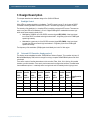
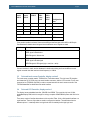
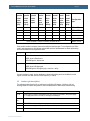
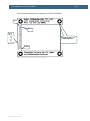
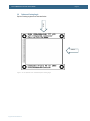
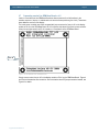
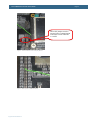
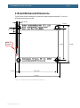
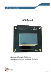
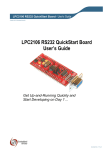
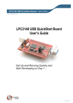
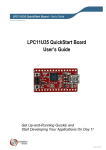
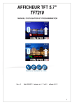
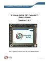
3.2 inch QVGA TFT Color LCD - User’s Guide Copyright 2012 © Embedded Artists AB 3.2 inch QVGA TFT Color LCD User’s Guide Version 1 & 2 Give graphics and color to your application! EA2-USG-0701 v2.1 Rev B 3.2 inch QVGA TFT Color LCD - User’s Guide Page 2 Embedded Artists AB Davidshallsgatan 16 SE-211 45 Malmö Sweden [email protected] http://www.EmbeddedArtists.com Copyright 2005-2012 © Embedded Artists AB. All rights reserved. No part of this publication may be reproduced, transmitted, transcribed, stored in a retrieval system, or translated into any language or computer language, in any form or by any means, electronic, mechanical, magnetic, optical, chemical, manual or otherwise, without the prior written permission of Embedded Artists AB. Disclaimer Embedded Artists AB makes no representation or warranties with respect to the contents hereof and specifically disclaim any implied warranties or merchantability or fitness for any particular purpose. Information in this publication is subject to change without notice and does not represent a commitment on the part of Embedded Artists AB. Feedback We appreciate any feedback you may have for improvements on this document. Please send your comments to [email protected]. Trademarks All brand and product names mentioned herein are trademarks, services marks, registered trademarks, or registered service marks of their respective owners and should be treated as such. Copyright 2012 © Embedded Artists AB 3.2 inch QVGA TFT Color LCD - User’s Guide Page 3 Table of Contents 1 Document Revision History 4 2 Introduction 5 2.1 Features 5 2.2 Version 1 vs. Version 2 5 2.3 ESD Precaution 6 2.4 General Handling Care 6 2.5 CE Assessment 6 2.6 Other Products from Embedded Artists 6 2.6.1 Design and Production Services 6 2.6.2 OEM / Education / QuickStart Boards and Kits 7 3 Design Description 8 3.1 Backlight Control 8 3.2 On-board LCD Controller, display version 2 8 3.3 On-board touch screen Controller, display version 2 9 3.4 On-board LCD Controller, display version 1 9 3.5 Interface (pin description) 10 3.6 Optimum Viewing Angle 13 3.7 Connecting version 2 to OEM Base Board < v1.5 14 4 Board Mechanical Dimensions Copyright 2012 © Embedded Artists AB 16 3.2 inch QVGA TFT Color LCD - User’s Guide Page 4 1 Document Revision History Revision Date Description v2.1 rev B 2012-01-13 Added this revision header. Added note about CE marking. Copyright 2012 © Embedded Artists AB 3.2 inch QVGA TFT Color LCD - User’s Guide Page 5 2 Introduction Thank you for buying Embedded Artists’ 3.2 inch QVGA TFT Color LCD Board based on a LCD from Truly. Sample applications for our NXP LPC2xxx based boards are also provided and can be downloaded from the support page. The 3.2 inch QVGA TFT Color LCD Board will be called the QVGA LCD Board for short in the rest of this document. 2.1 Features The QVGA LCD Board has the following features: Optional touch screen interface (available for version 2) 8-bit or 16-bit parallel interface. Only occupies 2 addresses (i.e., one address pin) or serial 8-bit (SPI-like) interface (max 10 MHz clock) Diagonal size: 3.2 inch Display technology: TFT Display mode: Transmissive No of pixels: 240xRGBx320 (QVGA size) Supply voltage: 3.0-3.3V White LED backlight, with PWM control View area: 48.6 x 64.8 mm Dot size: 0.2025 x 0.2025 mm Operating temperature: -20 to + 70 degrees Celsius No of colors: 262K (if 18-bit mode), 65k (if 16-bit mode) 2x20 pos connector (100 mil spacing) is required to interface the module, plus optional 1x6 pos connector Small form factor: 93 x 83 mm 2.2 Version 1 vs. Version 2 There exist two versions of the display. Version 1 uses a display from one display manufacturer and version 2 uses a display from another manufacturer. The similarities between the versions are: Same physical size of display module. Same optical features and capabilities. Same main 2x20 pos interface connector (100 mil spacing). The differences are: Different internal display controllers are used. The programming interface is not identical but very similar. A reference software driver exists that supports both versions simultaneous. Version 2 of the display module has a touch screen option. A 6 pos extra interface connector has been added beside the main 2x20 pos interface connector. This extra connector carries signals for touch screen interface and some extra signals for direct RGB-control of display (useful when interfacing the LPC2478 MCU from NXP). Copyright 2012 © Embedded Artists AB 3.2 inch QVGA TFT Color LCD - User’s Guide 2.3 Page 6 ESD Precaution Please note that the QVGA LCD Board comes without any case/box and all components are exposed for finger touches – and therefore extra attention must be paid to ESD (electrostatic discharge) precaution. Make it a habit always to first touch a ground pin/hole for a few seconds with both hands before touching any other parts of the boards. That way, you will have the same potential as the board and therefore minimize the risk for ESD. Note that Embedded Artists does not replace boards that have been damaged by ESD. 2.4 General Handling Care Handle the QVGA LCD Board with care. The boards are not mounted in a protective case/box and are not designed for rough physical handling. Connectors can ware out after excessive use. The QVGA LCD Board is designed for prototyping use, and not for integration into an end-product. Do not exercise excessive pressure on the LCD glass area. That will damage the display. Also, do not apply pressure on the flex cables connecting the LCD/touch screen. These are relatively sensitive and can be damaged if too much pressure is applied to them. Note that Embedded Artists does not replace boards where the LCD has been improperly handled. 2.5 CE Assessment The QVGA LCD Board is CE marked. See separate CE Declaration of Conformity document. The QVGA LCD Board is a class A product. In a domestic environment this product may cause radio interference in which case the user may be required to take adequate measures. EMC emission test has been performed on the QVGA LCD Board when connected to Embedded Artists base boards. Connecting the board to other devices may alter EMC emission. It is the user’s responsibility to make sure EMC emission limits are not exceeded when connecting the board to other devices. Due to the nature of the QVGA LCD Board – an evaluation board not for integration into an endproduct – fast transient immunity tests and conducted radio-frequency immunity tests have not been executed. Externally connected cables are assumed to be less than 3 meters. The general expansion connectors where internal signals are made available do not have any other ESD protection than from the chip themselves. Observe ESD precaution. Note that the QVGA LCD Board can also be considered to be a component if integrated into another product. The CE mark on the QVGA LCD Board cannot be extended to include the new (user created) product. It is the user’s responsibility to make sure EMC emission limits are not exceeded and CE mark the final product. 2.6 Other Products from Embedded Artists Embedded Artists have a broad range of LPC1000/2000/3000/4000 based boards that are very low cost and developed for prototyping / development as well as for OEM applications. Modifications for OEM applications can be done easily, even for modest production volumes. Contact Embedded Artists for further information about design and production services. 2.6.1 Design and Production Services Embedded Artists provide design services for custom designs, either completely new or modification to existing boards. Specific peripherals and I/O can be added easily to different designs, for example, communication interfaces, specific analog or digital I/O, and power supplies. Embedded Artists has a Copyright 2012 © Embedded Artists AB 3.2 inch QVGA TFT Color LCD - User’s Guide Page 7 broad, and long, experience in designing industrial electronics in general and with NXP’s LPC1000/2000/3000/4000 microcontroller families in specific. Our competence also includes wireless and wired communication for embedded systems. For example IEEE802.11b/g (WLAN), Bluetooth™, ZigBee™, ISM RF, Ethernet, CAN, RS485, and Fieldbuses. 2.6.2 OEM / Education / QuickStart Boards and Kits Visit Embedded Artists’ home page, www.EmbeddedArtists.com, for information about other OEM / Education / QuickStart boards / kits or contact your local distributor. Copyright 2012 © Embedded Artists AB 3.2 inch QVGA TFT Color LCD - User’s Guide Page 8 3 Design Description This chapter describes the hardware design of the QVGA LCD Board. 3.1 Backlight Control White LEDs are used as backlight on the display. The LED current is set to 15 mA. A step-up DC/DC converted is used to generate a constant LED current. The switching frequency is fixed to 1.2 MHz. The intensity of the backlight (i.e., the white LEDs) is varied by varying the LED current. There are two ways to very the LED current between 0-15 mA. A digital PWM signal is needed with the same logic levels as the power supply (typically 3.3V). Modulate the shutdown pin of the DC/DC converter (signal LED_SHDN). A low input signal turn off the DC/DC converted and a high level activate it. A high duty cycle on the PWM signal equals high intensity. Modulate the current set pin of the DC/DC converter (signal LED_PWM). A low input signal increase the LED current and a high level reduce it. A high duty cycle on the PWM signal equals low intensity. The frequency of the modulation (PWM) signal should ideally be in the 5-10 kHz region. 3.2 On-board LCD Controller, display version 2 The display has an embedded controller, SSD1289 from Solomon Systech. This controller chip has 1.3 Mbit embedded display RAM, which is enough for storing a complete 320xRGBx240 picture with 18 bit color depth. There are a couple of interface alternatives to this controller. Either 18-bit, 16-bit, 9-bit or 8-bit parallel interface or a serial interface. There are 4 pins that are used to configure the interface. The table below lists the different options. L is statically tied to low logic level and H is statically tied to high logic level. 18 bit parallel 16 bit parallel 9 bit parallel 8 bit parallel 18 bit parallel 16 bit parallel 9 bit 8 bit parallel parallel 6800style i/f 6800style i/f 6800style i/f 6800style i/f 8080style i/f 8080style i/f 8080style i/f 8080style i/f H H L L H H L L PS0 / CFG1 H H H H L L L L PS1 / CFG2 H L H L H L H L PS2 / CFG3 L H L H L H L H PS4 / CFG4 Copyright 2012 © Embedded Artists AB Configuration pins Does not matter. This pin is currently not used. CFG5 Does not matter. This pin is currently not used. CFG6 3.2 inch QVGA TFT Color LCD - User’s Guide 3-wire serial SPI i/f 4-wire serial SP Ii/f 6 bit RGB i/f H L H Page 9 16 bit RGB + 4-wire SPI i/f 18 bit RGB + 4-wire SPI i/f H L H PS0 / CFG1 H H H L PS1 / CFG2 H H L L L PS2 / CFG3 H H L L L PS4 / CFG4 Configuration pins Does not matter. This pin is currently not used. CFG5 Does not matter. This pin is currently not used. CFG6 If the parallel interface is selected, there are two different interface types; either 6800 or 8080 style. See datasheet for details about timing and how the different control signals are used. Interface Description 8080 style i86 interface RD/E signal is Read strobe WR/RW signal is Write strobe 6800 style M68 interface RD/E signal is Enable signal WR/RW signal is RW signal (high = read, low = write) If a serial interface is used, see the datasheet for details about timing and how the different control signals are used. Note that maximum clock frequency is 13 MHz. 3.3 On-board touch screen Controller, display version 2 The touch screen controller used is TSC2046 from Texas Instruments. This chip has a SPI interface and shares the SI, SO, SCK pins in the main interface connector, with the LCD controller. Pin 45 must however be low (TSC2046 chip CS#) in order to communicate with the touch screen controller. See TSC2046 datasheet for details about the serial interface. 3.4 On-board LCD Controller, display version 1 The display has an embedded controller, IS2102B from ISRON. This controller chip has 1.3 Mbit embedded display RAM, which is enough for storing a complete 320xRGBx240 picture with 18 bit color depth. There are a couple of interface alternatives to this controller. Either 16-bit or 8-bit parallel interface or a serial interface. There are 6 pins that are used to configure the interface. The table below lists the different options. L is statically tied to low logic level and H is statically tied to high logic level. Copyright 2012 © Embedded Artists AB 3.2 inch QVGA TFT Color LCD - User’s Guide Page 10 16 bit parallel 16 bit parallel 16 bit parallel 8 bit parallel 8 bit parallel 8 bit parallel 9 bit serial 8 bit serial 18-bit color depth 18-bit color depth 16-bit color depth 18-bit color depth 18-bit color depth 16-bit color depth 18-bit color depth 16-bit color depth (9+9) (16+2) (6+6+6) (8+8+2) (8+8) (9+9) (8+8) L L L L L L H H PSX / CFG1 H H L H H L - - DTX1 / CFG2 L H L L H H - - DTX2 / CFG3 L L L H H H H H BWS0 / CFG4 H H H H H H L H BWS1 / CFG5 Does not matter. This pin is currently not used. Set to L. Configuration pins BWS2 / CFG6 If the parallel interface is selected, there are two different interface types. The configuration pin C86 is used to select between the i86 interface and the M68 interface. See datasheet for details about timing and how the different control signals are used. C86 pin Description Low i86 interface RD/E signal is Read strobe WR/RW signal is Write strobe High M68 interface RD/E signal is Enable signal WR/RW signal is RW signal (high = read, low = write) If a serial interface is used, see the datasheet for details about timing and how the different control signals are used. Note that maximum clock frequency is 10 MHz. 3.5 Interface (pin description) The table below describes the 40 pin interface to the QVGA LCD Module. A 2x20 pos (100 mil spacing) header connector facing down is used. See datasheet for details about interface timing. Pin Description 1, 39 Power supply for QVGA LCD Module. Both pins must be connected to the power supply. Pin 1 supply the QVGA LCD and pin 39 supply the backlight. 2, 10, 40 Ground 3 CFG1 / PSX interface configuration pin (see description above) 4 C86 interface configuration pin (see description above). Not used on version 2. 5 CFG2 / DTX1 interface configuration pin (see description above) Copyright 2012 © Embedded Artists AB 3.2 inch QVGA TFT Color LCD - User’s Guide Page 11 6 CFG3 / DTX2 interface configuration pin (see description above) 7 CFG4 / BWS0 interface configuration pin (see description above) 8 BWS1 interface configuration pin (see description above). Not used on version 2. 9 BWS2 interface configuration pin (see description above). Not used on version 2. 11-12 D17-D16 data inputs if 18-bit color depth is used. Not used when 8 or 16-bit parallel interface is used. 13-28 D15-D0 databus. D0-D7 is used for 8-bit parallel interface. D0-D15 is used when 16-bit parallel interface is used. 29 CS – Chip Select, active low 30 RST – reset input, active low. 31 RS – Register Set input. Controls if control registers or display ram is accessed. Normally connected to A1 if 16-bit parallel interface or A0 if 8-bit interface. 32 WR/RW – Write strobe, active low, or Read/Write strobe (depending on C86 pin (v1) or CFG settings(v2)) 33 RD/E – Read strobe, active low, or Enable strobe (depending on C86 pin (v1) or CFG settings(v2)) 34 SI – Serial Input, if the serial interface is used. Set low if not used. 35 SCL – Serial Clock, if the serial interface is used. Set low if not used. 36 SO – Serial Output, if the serial interface is used. 37 LED_PWM, digital PWM signal input (5-10 kHz) for controlling the backlight. Low duty cycle = high intensity. Leave open if not used. 38 LED_SHDN, digital PWM signal input (5-10 kHz) for controlling the backlight. High duty cycle = high intensity. Leave open if not used. On display version 2 a new extra 1x6 pos (100 mil spacing) header connector facing down exists. See datasheet for details about interface timing. Pin Description 41 DOTCLK, needed when using RGB interface 42 HSYNC, needed when using RGB interface 43 VSYNC, needed when using RGB interface 44 DEN, needed when using RGB interface 45 Touch screen controller CS# 46 Touch screen controller PENIRQ# Copyright 2012 © Embedded Artists AB 3.2 inch QVGA TFT Color LCD - User’s Guide Page 12 The picture below illustrates the pin numbering of the QVGA LCD Module. Pin1 Pin2 On V2 Pin:46 45 44 43 42 41 Mounting holes x4 4.3mm diameter Pin40 Figure 1 - 3.2 inch QVGA TFT Color LCD Board Pin Numbering Copyright 2012 © Embedded Artists AB 3.2 inch QVGA TFT Color LCD - User’s Guide 3.6 Page 13 Optimum Viewing Angle Alt #1 Optimum viewing angles are as illustrated below. Alt #2 Figure 2 - 3.2 inch QVGA TFT Color LCD Board Optimum Viewing Angle Copyright 2012 © Embedded Artists AB 3.2 inch QVGA TFT Color LCD - User’s Guide 3.7 Page 14 Connecting version 2 to OEM Base Board < v1.5 Version 1.5 and above of the OEM Base Board has direct connectors for all 46 positions in the interface connector. Version 1.4 and below do not have the 6 extra positions (pos 41-46). These have been added for version2 of the display. The touch screen controller can still be accessed with just one extra wire, from pin 45 on the display module to P0.16 on the OEM Base Board. P0.16 is used for chip select of the touch screen controller. Other pins work just as well, but P0.16 is used on v1.5 and above of the OEM Base Board. Pin 45 Figure 3 - 3.2 inch QVGA TFT Color LCD Board Pin 45 Simply connect a wire from pin 45 on the display module to P0.16 on the OEM Base Board. Figure 4 and 5 below illustrate the wire connection. Also note that the three SPI jumpers must be inserted, see Figure 4 for details. Copyright 2012 © Embedded Artists AB 3.2 inch QVGA TFT Color LCD - User’s Guide Page 15 Three SPI jumpers must be inserted since communication with touch screen controller is via SPI. Figure 4 – Picture of Wire to Pin 45 on Display Module Figure 5 – Wire to p0.16 on OEM Base Board Copyright 2012 © Embedded Artists AB 3.2 inch QVGA TFT Color LCD - User’s Guide Page 16 4 Board Mechanical Dimensions Figure 6 below contains a drawing of the board that includes mechanical measures. Four 4.3 mm grounded mounting holes are used. 2x2.54 mm 6.5 mm 10.7 mm Only on version 2 70 mm 6.5 mm 80.0 mm 93 mm Figure 6 - 3.2 inch QVGA TFT Color LCD Board Mechanical Dimensions Copyright 2012 © Embedded Artists AB 83 mm