
1
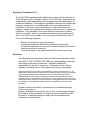
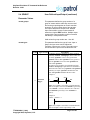
AT Command Doc :
TT8740AN001
Skypatrol Evolution
AT Command Set Reference
Release 1.09A
Confidential and Proprietary Information – © 2005 Skypatrol, LLC.
Do not duplicate without express permission from Skypatrol, LLC.
Document Title:
SkyPatrol Evolution
AT Command Set Reference
Version:
1.09
Date:
03/14/08
Status:
Released
Document Control ID:
TT8740AN001
General
All efforts have been made to ensure the accuracy of material provided in this
document at the time of release. However, the items described in this document are
subject to continuous development and improvement. All specifications are subject to
change without notice and do not represent a commitment on the part of SkyPatrol
LLC. SkyPatrol, Inc. will not be responsible for any loss or damages incurred related to
the use of information contained in this document.
This product is not intended for use in life support appliances, devices or systems
where a malfunction of the product can reasonably be expected to result in personal
injury. SkyPatrol, Inc. customers using, integrating, and/or selling this product for use in
such applications do so at their own risk and agree to fully indemnify SkyPatrol LLC. for
any damages resulting from illegal use or resale.
Copyright
Complying with all applicable copyright laws is the responsibility of the user. Without
limiting the rights under copyright, no part of this document may be reproduced, stored
in or introduced into a retrieval system, or transmitted in any form or by any means
(electronic, mechanical, photocopying, recording or otherwise), or for any purpose,
without the express written permission of SkyPatrol LLC.
SkyPatrol may have patents, patent applications, trademarks, copyrights or other
intellectual property rights covering subject matter in this document. Except as
expressly provided in any written license agreement from SkyPatrol, the furnishing of
this document does not give you any license to these patents, trademarks, copyrights or
other intellectual property.
©2005 -2007 Skypatrol, LLC. All rights reserved.
Enabler is a registered trademark of Enfora in the United States.
Regulatory Compliance FCC
The EVOLUTION has been tested and found to comply with the limits for a
Class B digital device, pursuant to part 15 of the FCC rules. These limits are
designed to provide reasonable protection against harmful interference in a
residential installation. This equipment generates, uses and can radiate radio
frequency energy and, if not installed and used in accordance with the
instructions, may cause harmful interference to radio communications.
However, there is no guarantee that interference will not occur in a particular
installation. If this equipment does cause harmful interference to radio or
television reception, which can be determined by turning the equipment off
and on, the user is encouraged to try to correct the interference by one or
more of the following measures:
-
Reorient or relocate the receiving antenna
Increase the separation between the equipment and receiver
Connect the equipment into an outlet on a circuit different from that to
which the receiver is connected
Consult the dealer or an experienced radio/TV technician for help.
Disclaimer
The information and instructions contained within this publication comply
with all FCC, GCF, PTCRB, RTTE, IMEI and other applicable codes that
are in effect at the time of publication. Skypatrol disclaims all
responsibility for any act or omissions, or for breach of law, code or
regulation, including local or state codes, performed by a third party.
Skypatrol strongly recommends that all installations, hookups, transmissions, etc., be
performed by persons who are experienced in the fields of radio frequency technologies.
Skypatrol acknowledges that the installation, setup and transmission guidelines
contained within this publication are guidelines, and that each installation may have
variables outside of the guidelines contained herein. Said variables must be taken into
consideration when installing or using the product, and Skypatrol shall not be responsible
for installations or transmissions that fall outside of the parameters set forth in this
publication.
Skypatrol shall not be liable for consequential or incidental damages,
injury to any person or
property, anticipated or lost profits, loss of time, or other losses incurred
by Customer or any third party in connection with the installation of the
Products or Customer's failure to comply with the information and
instructions contained herein.
Warranty Information
LIMITED WARRANTIES. The following limited warranties give you specific legal rights.
You may have others, which vary from state/jurisdiction to state/jurisdiction.
Hardware Limited Warranty. SKYPATROL warrants that the Product shall be free from
defects in materials and workmanship and will substantially conform to SKYPATROL’s
applicable published specifications for the Products for a period of one (1) year from the
date of original purchase. THIS WARRANTY IS VOID IF THE PRODUCT CASING IS
OPENED BY ANYONE OTHER THAN A SKYPATROL AUTHORIZED SERVICE
FACILITY. The warranty set forth in this paragraph shall not apply to the Software.
Software Limited Warranty. The Software is licensed and not sold. Its use is governed by
the provisions of the applicable End User License Agreement (“EULA”), if any, included
with the Software. In the absence of a separate EULA included with the Software
providing different limited warranty terms, exclusions, and limitations, the following terms
and conditions shall apply. SKYPATROL warrants that the Software will substantially
conform to the applicable published specifications for the Software for a period of ninety
(90) days from the date of valid activation. SKYPATROL does not warrant that the
operation of the Software will be error-free or uninterrupted or that the Software
functions will meet your requirements or that all defects in the Software will be corrected.
THIS WARRANTY IS VOID IF YOU BREACH THE SOFTWARE LICENSE SET FORTH
ABOVE.
WARRANTY REMEDIES. SKYPATROL’s sole liability and your exclusive remedy under
the warranties set forth above shall be, at SKYPATROL’s option, to repair or replace any
Product or Software that fails to conform to such warranty (“Nonconforming Product”), or
refund the purchase price paid by you for any such Nonconforming Product, upon your
return of any Nonconforming Product to SKYPATROL or, if you purchased the Product
from an Authorized Distributor, to such Authorized Distributor, in accordance with
SKYPATROL’s or such Authorized Distributor’s standard return material authorization
procedures. The foregoing notwithstanding SKYPATROL will not pay for (i) costs of
installation or removal, (ii) costs of product set-up or adjustment, or (iii) shipping or
related charges of returning the Product for repair, regardless of whether the repair is
covered by the Limited Warranty set forth above. You must pay for shipment of the
Product to the nearest SKYPATROL Authorized Service Facility and, if the warranty
claim is valid, SKYPATROL will pay for shipment of the repaired or replaced Product
back to you. You must provide a purchase receipt or other proof of the date of original
purchase before warranty service will be rendered. All replaced parts and products, and
products on which a refund is made, become the property of SKYPATROL. Unless
prohibited by law, new or reconditioned parts and Products may be used in the
performance of warranty service. Repaired or replaced parts and Products are
warranted for the remainder of the original limited warranty period. You will be charged
for the repair or replacement of the Product made after the expiration of the warranty
period.
WARRANTY EXCLUSIONS AND DISCLAIMER. The preceding warranties are
conditioned upon submission of a purchase receipt or other proof of the date of original
purchase and the preceding warranties shall not apply to, and SKYPATROL shall not be
responsible for: (1) damage, failure or malfunction caused by or attributable to acts of
God, lightning or other incidence of excess voltage or current, fresh or salt water
immersion or spray, abuse, neglect, accident, misuse, alteration, cosmetic damage or
any other occurrence beyond the reasonable control of SKYPATROL; (2) the Products
and Software if they are not properly and correctly installed, configured, interfaced,
maintained, stored, and operated in accordance with the relevant operator's manual and
specifications; (3) Services not provided by SKYPATROL; (4) the combination or
utilization of the Product or Software with accessories, products, information, data,
systems, devices or ancillary or peripheral equipment not made, supplied or specified by
SKYPATROL; (5) the operation of the Product or Software under any specification other
than, or in addition to, the standard specifications for the Product or Software; (6) the
Product and Software if the serial number has been removed or defaced; (7) any repairs
other than those provided by a SKYPATROL Authorized Service Facility; (8)
consumable parts (e.g., batteries and fuses); (9) the unauthorized modification or use of
the Product or Software; (10) use of the Product without a valid license for the Software;
or (11) any shipment of the Product (claims must be presented to the carrier).
THE WARRANTIES ABOVE STATE SKYPATROL’S ENTIRE LIABILITY, AND YOUR
EXCLUSIVE REMEDIES, RELATING TO PERFORMANCE OF THE PRODUCTS AND
SOFTWARE. EXCEPT AS OTHERWISE EXPRESSLY PROVIDED HEREIN, THE
PRODUCTS, THE PROPRIETARY INFORMATION, AND ACCOMPANYING
ACCESSORIES AND MATERIALS ARE PROVIDED “AS-IS” AND WITHOUT
EXPRESS OR IMPLIED WARRANTY OF ANY KIND BY SKYPATROL, ITS
AUTORIZED DISTRIBUTORS OR ANYONE ELSE WHO HAS BEEN INVOLVED IN ITS
CREATION, PRODUCTION, INSTALLATION, OR DISTRIBUTION INCLUDING,
WITHOUT LIMITATION, THE IMPLIED WARRANTIES OF MERCHANTABILITY AND
FITNESS FOR A PARTICULAR PURPOSE, TITLE AND NONINFRINGEMENT. THE
STATED EXPRESS WARRANTIES ARE IN LIEU OF ALL OBLIGATIONS OR
LIABILITIES ON THE PART OF SKYPATROL ARISING OUT OF, OR IN CONNECTION
WITH, ANY PRODUCTS OR PROPRIETARY INFORMATION. SKYPATROL IS NOT
RESPONSIBLE FOR THE OPERATION OR FAILURE OF OPERATION OF GPS
SATELLITES OR THE AVAILABILITY OF GPS SATELLITE SIGNALS. IF ANY IMPLIED
WARRANTY APPLIES TO THE PRODUCT OR THE PROPRIETARY INFORMATION,
SUCH IMPLIED WARRANTY IS LIMITED IN DURATION TO THE DURATION OF THE
EXPRESS LIMITED WARRANTY SET FORTH ABOVE. SOME STATES AND
JURISDICTIONS DO NOT ALLOW LIMITATIONS ON DURATION OR THE
EXCLUSION OF AN IMPLIED WARRANTY, SO THE ABOVE LIMITATION MAY NOT
APPLY TO YOU. YOU MAY ALSO HAVE ADDITIONAL RIGHTS NOT STATED IN THIS
DOCUMENT. IF ANY PORTION OF THE LIMITED WARRANTY PROVIDED HEREIN
IS ILLEGAL OR UNENFORCEABLE, SUCH PARTIAL ILLEGALITY OR
UNENFORCEABILITY SHALL NOT AFFECT THE REMAINDER OF THE LIMITED
WARRANTY.
This Limited Warranty allocates the risk of Product and Software failure between you
and SKYPATROL, and SKYPATROL’s pricing of the Product reflects this allocation of
risk and the limitations of liability set forth below. The agents, employees, distributors
and dealers of SKYPATROL are not authorized to make modifications to the Limited
Warranties set forth herein, or make additional warranties binding on SKYPATROL.
Accordingly, additional statements such as dealer advertising or presentation, whether
oral or written, do not constitute warranties by SKYPATROL and should not be relied
upon.
LIMITATION OF LIABILITY. SKYPATROL’S ENTIRE LIABILITY UNDER ANY
PROVISION HEREIN SHALL BE LIMITED TO THE GREATER OF THE AMOUNT PAID
BY YOU FOR THE PRODUCT OR SOFTWARE LICENSE OR U.S.$25.00. TO THE
MAXIMUM EXTENT PERMITTED BY APPLICABLE LAW, IN NO EVENT SHALL
SKYPATROL OR ITS SUPPLIERS BE LIABLE FOR ANY INDIRECT, SPECIAL,
INCIDENTAL OR CONSEQUENTIAL DAMAGES WHATSOEVER UNDER ANY
CIRCUMSTANCE OR LEGAL THEORY RELATING IN ANY WAY TO THE
PRODUCTS, PROPRIETARY INFORMATION AND ACCOMPANYING ACCESSORIES
AND MATERIALS, (INCLUDING, WITHOUT LIMITATION, DAMAGES FOR LOSS OF
BUSINESS PROFITS, BUSINESS INTERRUPTION, LOSS OF BUSINESS
INFORMATION, OR ANY OTHER PECUNIARY LOSS), REGARDLESS OF WHETHER
SKYPATROL HAS BEEN ADVISED OF THE POSSIBILITY OF ANY SUCH LOSS AND
REGARDLESS OF THE COURSE OF DEALING WHICH DEVELOPS OR HAS
DEVELOPED BETWEEN YOU AND SKYPATROL, EVEN IF SUCH DAMAGES ARISE
FROM THE NEGLIGENCE OF SKYPATROL AND/OR ITS AGENTS. BECAUSE SOME
STATES AND JURISDICTIONS DO NOT ALLOW THE EXCLUSION OR LIMITATION
OF LIABILITY FOR CONSEQUENTIAL OR INCIDENTAL DAMAGES, THE ABOVE
LIMITATION MAY NOT APPLY TO YOU.
YOU ACKNOWLEDGE THAT THE PRODUCT MAY ALLOW YOU, AT YOUR
DISCRETION, TO RECEIVE WHERE AVAILABLE FROM AN AUTHORIZED
DISTRIBUTOR SERVICES ENABLED THROUGH THE USE OF THE PRODUCT, AND
YOU IRREVOCABLY AND ABSOLUTELY AGREE THAT UNLESS YOU HAVE
PURCHASED SUCH SERVICES DIRECTLY FROM SKYPATROL, SKYPATROL
SHALL NOT BE LIABLE IN CONNECTION WITH ANY ACTIONS, OMISSIONS OR
OTHER OCCURRENCES WITH RESPECT TO SUCH SERVICES PROVIDED BY AN
AUTHORIZED DISTRIBUTOR.
Date
Rev
Author
JANUARY 24,
2008
DRAFT
R. Sanchez
J. Blanco
MARCH 20,
2008
DRAFT
R. Sanchez
J. Blanco
C. Moreno
Description
Draft
Draft
Table of Contents
1
INTRODUCTION..................................................................................................... 3
1.1
1.2
1.3
1.4
2
DOCUMENT SCOPE ............................................................................................... 3
PLATFORM REFERENCE AND USE ......................................................................... 3
COMMAND SYNTAX ............................................................................................. 3
REVISION HISTORY .............................................................................................. 3
AT COMMANDS...................................................................................................... 3
2.1
2.2
2.3
2.4
2.5
2.6
2.7
2.8
2.9
2.10
2.11
2.12
2.13
2.14
2.15
2.16
2.17
2.18
2.19
2.20
2.21
2.22
2.23
2.24
2.25
2.26
AUTOMATIC PIC RESET ....................................................................................... 3
DELETE A RANGE OF EVENT GROUPS .................................................................. 3
DELETE A RANGE OF GEO-FENCES ...................................................................... 3
EVENT ............................................................................................................... 3
EVENT QUERY ..................................................................................................... 3
EVENT COUNTER ................................................................................................. 3
GEO-FENCING ...................................................................................................... 3
GEOFENCE DEBOUNCE ......................................................................................... 3
GPS LOCAL SUBSCRIPTION.................................................................................. 3
GPS ODOMETER .................................................................................................. 3
GPS OVERSPEED INTERVAL................................................................................. 3
GPS QUALITY FILTERS ........................................................................................ 3
GPS READ ........................................................................................................... 3
IGNITION DEBOUNCE ........................................................................................... 3
I/O DEBOUNCE..................................................................................................... 3
MESSAGE LOG CLEAR ......................................................................................... 3
MESSAGE LOG DUMP ........................................................................................... 3
MESSAGE LOG ENABLE ....................................................................................... 3
MESSAGE LOG READ DATA ................................................................................. 3
MESSAGE SEND ................................................................................................... 3
ODOMETER .......................................................................................................... 3
POWER SAVE ....................................................................................................... 3
REAL TIME CLOCK ALARM .................................................................................. 3
REMOTE TAIP ..................................................................................................... 3
TAIP.................................................................................................................... 3
SCRIPT VERSION .................................................................................................. 3
APPENDIX A – DEFAULT AT VALUES ..................................................................... 3
SkyPatrol Evolution AT Command Set Reference
Revision 1.09A
1 Introduction
1.1 Document Scope
This documentation pertains to the AT Command Set to be used in conjunction
with the SkyPatrol Evolution series units.
1.2 Platform Reference and Use
The SkyPatrol Evolution series unit will be referred to using various terms, to
include: MS (Mobile Station), TA (Terminal Adapter), DCE (Data
Communication Equipment), or ME (Mobile Equipment).
The SkyPatrol Evolution series unit can be controlled via the use of a DTE (Data
Terminal Equipment) platform by issuing the AT commands via a serial
interface.
1.3 Command Syntax
The attention or “AT” prefix is required prior to entering any command. All
commands require a carriage return or <CR> following the entry of the desired
command. All command responses are encapsulated by a carriage return and
line feed or <CR><LF>. The ASCII display of these characters is suppressed
with only the modem response being presented.
The following examples demonstrate the potential usage of AT commands
presented:
Type
Command Format
Query
Command Read
Command Write
Command Execution
Example
AT$GXXX=?
Description
When entered will
return the command
format and value
ranges.
AT$GXXX?
When entered will
return the current valu
assigned to the
command.
AT$GXXX=<value>,<value>,… When entered will set
the command to
specified value(s).
AT$GXXX
When entered will
execute the specified
command.
TT8740AN001 (1.09a)
Copyright 2005, SkyPatrol, LLC.
Page 9 of 65
SkyPatrol Evolution AT Command Set Reference
Revision 1.09A
1.4
Revision History
Date
2/5/03
4/29/03
6/06/03
Rev
Draft
1.00
1.01
Author
C. Patel
C. Patel
C. Patel
6/10/03
1.02 C. Patel
6/13/03
11/11/03
1.03 M.Glover
1.04 C. Patel
08/22/05
11/15/05
2/12/07
1.05 D. ONeil
1.06 D. ONeil
1.07 D. ONeil
11/16/07
1.08 D. ONeil
01/24/08
1.09 D. ONeil
TT8740AN001 (1.09a)
Copyright 2005, SkyPatrol, LLC.
Description
Initial Draft.
Initial Release.
Modified and update description of all the commands.
Added $EVENT command.
Update $EVENT command: Parm1 and Parm2 definition
for “Output Flash Event”
Added AT$NETMON command reference
Added AT$GPSODOM command. Updated
AT$PWRSAV, AT$GEOFNC, and AT$EVENT
commands.
Added $MSGLOGEN, $MSGLOGRD, $MSGSND
Corrected $MSLOGEN command
Edited Input and Output tables in $EVENT
Added $RTCALRM
Added $IGNDBNC
Added $GFDBNC
Added Input Event 65
Edited Output Event 45
Added Output Events 54 – 58
Added $HBRST
Added $USRVAL
Added $GPSOSI
Added Input Event 71
Added Bit 24 to Parm2 value table
Added $IODBNC
Added Event 72
Added $EVDELR, $GFDEL
Added output event 59
Added input events 66-69 (timers 5-8)
Edited input event 71
Added output event 60
Edited Bit 6
Added $GPSQUAL
Added $MSGLOGDMP
Page 10 of 65
SkyPatrol Evolution AT Command Set Reference
Revision 1.09A
2 AT Commands
2.1 Automatic PIC Reset
$HBRST
Automatic PIC Reset
Command Function
This command allows the user to program
the reset interval.
Command Functional
Group
SkyPatrol Specific
Command Format Query
AT$HBRST=?
$HBRST:(0,4-168)
OK
Response
Write Format
Response
AT$HBRST=<hours>
<cr>
OK
Read Format
Response
AT$HBRST?
$HBRST:<hours>
OK
Execution Format
Response
N/A
N/A
Parameter Values
<hours>
0 = Off
4-168 = Number of hours until we stop
providing heartbeat pulse to PIC
Reference
N/A
Standard Scope
Optional
Implementation Scope
Full
TT8740AN001 (1.09a)
Copyright 2005, SkyPatrol, LLC.
Page 11 of 65
SkyPatrol Evolution AT Command Set Reference
Revision 1.09A
2.2
Delete a Range of Event Groups
$EVDELR
Delete a Range of Event Groups
Command Function
This command deletes a range of event
groups.
Command Functional
Group
SkyPatrol Specific
Command Format Query
Response
AT$EVDELR=?
$EVDELR: (0-99),(0-99)
OK
Write Format
Response
AT$EVDELR=<start>,<stop>
OK
Read Format
Response
N/A
N/A
Execution Format
Response
N/A
N/A
Parameter Values
<start>
First group index in range to be deleted
<stop>
Last group index in range to be deleted.
Reference
N/A
Standard Scope
Optional
Implementation Scope
Full
Notes
This feature is available in software
version 0.7.8 pkg 43, and later.
TT8740AN001 (1.09a)
Copyright 2005, SkyPatrol, LLC.
Page 12 of 65
SkyPatrol Evolution AT Command Set Reference
Revision 1.09A
2.3
Delete a Range of Geo-Fences
$GFDEL
Delete a Range of Geo-Fences
Command Function
This command deletes a range of geofences.
Command Functional
Group
SkyPatrol Specific
Command Format Query
Response
AT$GFDEL=?
$GFDEL: (1-25),(1-25)
OK
Write Format
Response
AT$GFDEL=<start>,<stop>
OK
Read Format
Response
N/A
N/A
Execution Format
Response
N/A
N/A
Parameter Values
<start>
First geo-fence index in range to be
deleted
<stop>
Last geo-fence index in range to be
deleted.
Reference
N/A
Standard Scope
Optional
Implementation Scope
Full
Notes
This feature is available in software
version 0.7.8 pkg 43, and later.
TT8740AN001 (1.09a)
Copyright 2005, SkyPatrol, LLC.
Page 13 of 65
SkyPatrol Evolution AT Command Set Reference
Revision 1.09A
2.4 EVENT
$EVENT
User Defined Input/Output
Command Function
This command allows the user to
customize the modem’s input and output
capabilities. Any combination of input
events can be monitored to trigger any
combination of output events.
Command Functional
Group
SkyPatrol Specific
Command Format Query
Response
AT$EVENT=?
$EVENT: (0-99),(0-3),(0-255),(2147483647 - 2147483647),(-2147483647
- 2147483647)
Write Format
Response
AT$EVENT=<event group>,<event
type>,<event category>,<parm1>,
<parm2>
OK
Read Format
Response
AT$EVENT?
$EVENT: evgp
1A
1B
2A
2B
3A
3B
4A
4B
5A
5B
6A
6B
Execution Format
Response
N/A
TT8740AN001 (1.09a)
Copyright 2005, SkyPatrol, LLC.
evtyp
0
3
0
3
0
3
0
3
0
3
0
3
evcat
27
22
27
14
9
37
9
21
9
13
9
21
p1
1
0
0
0
2
1
5
0
0
0
1
0
p2
1
0
0
0
4
0
5
0
0
0
1
0
Page 14 of 65
SkyPatrol Evolution AT Command Set Reference
Revision 1.09A
2.4 $EVENT
User Defined Input/Output (continued)
Parameter Values
<event group>
This parameter defines the group number of a
group of events and the order they are executed.
Events are grouped together to control execution
sequence. A group number has to have at least
one input event and one output event. Multiple
input events within a group number would be
treated as a logical AND condition. Multiple output
events within a group number would be executed
individually in a sequential manner.
Valid values for group number are: 1 thru 99.
<event type>
This parameter defines the type of event: Input or
Output. An Input event can be defined as:
Transition, Occurrence, or Input. The output event
is executed when input event conditions are met.
Value
Type of event
Description
A transition Trigger is defined as an input condition,
defined by <event category>, whose value was
previously <parm1> or less is now greater than
<parm1> and less than <parm2> or was greater or
equal to <parm2> is now less than <parm2> but
greater than <parm1>.
The output event would be executed when an input
<event category> requirements are satisfied or
transition to the value set by <parm1> and <parm2>
when they are equal. <parm1> should be the min
value and <parm2> should be the max value.
Example 1:
Parm1
0
Transition
Trigger
0
Parm2
Max
Figure 1. An output event will be executed when the
value of an input event exceeds <Parm1> (previously
it was <Parm1> or less) or decreases to a value less
than <Parm2> (previously it was <Parm2> or
greater).
Example 2:
Parm1 = Parm2 = 0
0
1
Figure 2. An output event will be executed when the
value of an input event is 0 (previously it was
TT8740AN001 (1.09a)
Copyright 2005, SkyPatrol, LLC.
Page 15 of 65
SkyPatrol Evolution AT Command Set Reference
Revision 1.09A
anything else but 0) and <Parm1> along with
<Parm2> is set to 0.
Example 3:
Parm1 = Parm2 = 1
0
1
Figure 3. An output event will be executed when the
value of an input event is 1 (previously it was
anything else but 1) and <Parm1> along with
<Parm2> is set to 1.
An Occurrence Trigger is defined as an input
condition, defined by <event category>, whose
current value is greater than or equal to <parm1> and
less than or equal to <parm2>.
The output event would be executed when an input
<event category> requirements are satisfied or
transition to the value set by <parm1> and <parm2>
when they are equal. <parm1> should be the min
value and <parm2> should be the max value
Example 4:
Parm1
0
1
Occurrence
Trigger
Parm2
Max
Figure 4. An output event will be executed when the
current value of an input event is between <Parm1>
and <Parm2> including boundary conditions.
Example 5:
Parm1 = 0
Parm2 = 1
0
1
Figure 5. An output event will be executed when the
value of the input event changes from 0 to 1 or viceversa.
Example 6:
Parm1 = Parm2 = 1
0
1
Figure 6. An output event will be executed when the
value of the input event is 1 and <Parm1> along with
<Parm2> is set to 1.
2
TT8740AN001 (1.09a)
Copyright 2005, SkyPatrol, LLC.
Input Trigger
An Input Trigger is defined as an input condition,
defined by <event category>, that should be
used as a logical AND condition to another input
Page 16 of 65
SkyPatrol Evolution AT Command Set Reference
Revision 1.09A
3
condition defined as Transition Trigger or an
Occurrence Trigger. An Output event is not triggered
when Input Trigger condition is valid.
The input event, defined as Input Trigger, is valid
when within the event range defined by <parm1>
and <parm2> or when <parm1> and <parm2> are
equal.
An Output event is executed when all input event
conditions (defined as Transition Trigger, Occurrence
Trigger, or Input Trigger) for that particular <event
group> are met.
Output
<event category>
This parameter defines the actual Input or Output
Event number and their valid range for <parm1>
and <parm2>.
The below table defines the values for <event
category>, <parm1> and <parm2> parameter for
input events defined as a Transition Trigger,
Occurrence Trigger, or Input Trigger.
event
Parm1
category
0
0 or 1
1
2
0 or 1
0 or 1
3
0 or 1
4
0 or 1
5
6
7
8
0 or 1
0 or 1
0 or 1
1
9
0 to 5
10
0 to 8
11
0 or 1
12
13
14
15
1
1
1
1
0 to
1000000
16
TT8740AN001 (1.09a)
Copyright 2005, SkyPatrol, LLC.
Parm2 Description
GPIO1 – General purpose Input/Output #1
0 or 1 0 = Low
1 = High
0 or 1 GPIO2 – General purpose Input/Output #2
0 or 1 GPIO3 – General purpose Input/Output #3
GPIO4 – General purpose Input/Output #4
0 or 1 0 = Main battery disconnected
1 =Main battery connected
GPIO5 – General purpose Input/Output #5
Controls the RESET line of the GPS receiver.
0 or 1
0 = Turn OFF the GPS receiver.
1 = Turn ON the GPS receiver.
0 or 1 GPIO6 – General purpose Input/Output #6
0 or 1 GPIO7 – General purpose Input/Output #7
0 or 1 GPIO8 – General purpose Input/Output #8
1
Modem power up indication
Modem GSM registration (see AT+CREG
0 to 5 command description for GSM registration status
information)
Modem GPRS registration (see AT%CGREG
0 to 8 command description for GPRS registration status
information)
Receipt of IP address.
0 or 1 0 = No IP address
1 = Valid IP address obtained
1
Timer 1 (set by AT$EVTIM1)
1
Timer 2 (set by AT$EVTIM2)
1
Timer 3 (set by AT$EVTIM3)
1
Timer 4 (set by AT$EVTIM4)
GPS Distance (unit of measurement is: meters)
1000000
Page 17 of 65
SkyPatrol Evolution AT Command Set Reference
Revision 1.09A
17
18
19
0 to 250
0 to
1760
0 to
1760
250
1760
1760
20
21
0 or 1
0 or 1
22
23
24
25
0 or 1
0 or 1
0 or 1
0 or 1
0 or 1
0 or 1
0 or 1
0 or 1
26
0 or 1
0 or 1
27
0 or 1
0 or 1
28
1
1
29
0 to
1000000
1000000
30
0 to
1000000
1000000
31
0 or 1
0 or 1
32
33
34
35
36
37
38
39
40
41
42
43
44
45
46
47
48
49
50
0 or 1
0 or 1
0 or 1
0 or 1
0 or 1
0 or 1
0 or 1
0 or 1
0 or 1
0 or 1
0 or 1
0 or 1
0 or 1
0 or 1
0 or 1
0 or 1
0 or 1
0 or 1
0 or 1
0 or 1
0 or 1
0 or 1
0 or 1
0 or 1
0 or 1
0 or 1
0 or 1
0 or 1
0 or 1
0 or 1
0 or 1
0 or 1
0 or 1
0 or 1
0 or 1
0 or 1
0 or 1
0 or 1
51
0
0
TT8740AN001 (1.09a)
Copyright 2005, SkyPatrol, LLC.
Maximum Velocity (unit of measurement is:
Knots)
**Analog/Digital 1
**Analog/Digital 2
Reserved
Geo Fence #1. See AT$GEOFNC command for
details on setting a circular geo-fence
0 = Leaving Geofence area
1 = Entering Geofence area
Geo Fence #2
Geo Fence #3
Geo Fence #4
Geo Fence #5
MT Power Save Event
0 = Exit Power Save Mode
1 = Enter Power Save Mode
GPS Status
0 = Invalid GPS data
1 = Valid GPS data
**RTC Alarm Input
Invalid GPS data for a period of time (unit of
measurement is: seconds). Will execute at twice
the value of Param1.
Unit staying Idle in one place (unit of
measurement is: seconds). Will execute at twice
the value of Param1.
Geo Fence #6. See AT$GEOFNC command for
details on setting a circular geo-fence
0 = Leaving Geofence area
1 = Entering Geofence area
Geo Fence #7
Geo Fence #8
Geo Fence #9
Geo Fence #10
Geo Fence #11
Geo Fence #12
Geo Fence #13
Geo Fence #14
Geo Fence #15
Geo Fence #16
Geo Fence #17
Geo Fence #18
Geo Fence #19
Geo Fence #20
Geo Fence #21
Geo Fence #22
Geo Fence #23
Geo Fence #24
Geo Fence #25
**Input Event Counter. This event will occur
when a counter reaches the maximum number of a
selected Input event count.
Page 18 of 65
SkyPatrol Evolution AT Command Set Reference
Revision 1.09A
52
53
54
55
56
57
58
59
60
61
62
63
64
New SMS indication.
0 or 1 0 = SMS message read from SIM
1 = New SMS message received
Current Input Event Counter count that can be
0 to -1 0 to –1
used as an AND condition with other input events
Has the user programmed any geo-fence?
Normally this can be found by sending
AT$GEOFNC? command and verifying it
0 or 1
0 or 1
manually based on the response sent by the device
0 = geo-fence does not exists
1 = at least one geo fence was created
N/A
N/A Reserved
N/A
N/A Reserved
N/A
N/A Reserved
N/A
N/A Reserved
0-100
0-100 Battery level as a percentage
0 – 9999 0 – 9999 Number of Unsent Messages ($msglogrd count)
0 – 100 0 – 100 Memory full percentage ($msglogrd)
0 or 1
65
1 to 5
66
67
68
69
70
1
1
1
1
N/A
71
0-3
72
0-1
Receipt of Incoming Call with Call Identifier
matching one the numbers configured via the
1 to 5 $EVCID command. <Parm1> and <Parm2>
correspond to range $EVCID entries which will
generate the input event.
1
Timer 5 (set by AT$EVTIM5)
1
Timer 6 (set by AT$EVTIM6)
1
Timer 7 (set by AT$EVTIM7)
1
Timer 8 (set by AT$EVTIM8)
N/A Reserved
GPS Antenna Status
0 = unknown
0-3 1 = good
2 = open
3 = short
0 = A GPS overspeed interval has ended
0-1
1 = A GPS overspeed interval has begun
The below table defines the values for <event category>, <parm1>
and <parm2> parameter for output events defined as Output.
event
Parm1 Parm2 Description
category
0
0
0
Changes GPIO #1 to Input (from Output)
1
0
0
Changes GPIO #2 to Input (from Output)
2
0
0
Changes GPIO #3 to Input (from Output)
3
0
0
Changes GPIO #4 to Input (from Output)
4
0
0
Changes GPIO #5 to Input (from Output)
5
0
0
Changes GPIO #6 to Input (from Output)
6
0
0
Changes GPIO #7 to Input (from Output)
7
0
0
Changes GPIO #8 to Input (from Output)
8
0
0
Set GPIO #1 configured as Output to Low (0)
9
0
0
Set GPIO #2 configured as Output to Low (0)
TT8740AN001 (1.09a)
Page 19 of 65
Copyright 2005, SkyPatrol, LLC.
SkyPatrol Evolution AT Command Set Reference
Revision 1.09A
10
11
12
13
14
15
16
17
18
19
20
21
22
23
24
25
26
27
28
29
30
31
32
33
34
35
36
37
38
39
40
0
0
0
0
0
0
0
0
0
0
0
0
0
0
0
0
0
0
0
0
0
0
0
0
0
0
0
0
0
0
0
0
0
0
0
0
0
0
0
0
0
0
0
0
See GPIO Flash
Table below
41
0 to –1
See BitField
Table
below
1–4
0
1 – 15
0
42
43
44
TT8740AN001 (1.09a)
Copyright 2005, SkyPatrol, LLC.
Set GPIO #3 configured as Output to Low (0)
Set GPIO #4 configured as Output to Low (0)
Set GPIO #5 configured as Output to Low (0)
Set GPIO #6 configured as Output to Low (0)
Set GPIO #7 configured as Output to Low (0)
Set GPIO #8 configured as Output to Low (0)
Set GPIO #1 configured as Output to High (1)
Set GPIO #2 configured as Output to High (1)
Set GPIO #3 configured as Output to High (1)
Set GPIO #4 configured as Output to High (1)
Set GPIO #5 configured as Output to High (1)
Set GPIO #6 configured as Output to High (1)
Set GPIO #7 configured as Output to High (1)
Set GPIO #8 configured as Output to High (1)
Toggle GPIO #1 configured as Output
Toggle GPIO #2 configured as Output
Toggle GPIO #3 configured as Output
Toggle GPIO #4 configured as Output
Toggle GPIO #5 configured as Output
Toggle GPIO #6 configured as Output
Toggle GPIO #7 configured as Output
Toggle GPIO #8 configured as Output
Flash GPIO #1 configured as Output
Flash GPIO #2 configured as Output
Flash GPIO #3 configured as Output
Flash GPIO #4 configured as Output
Flash GPIO #5 configured as Output
Flash GPIO #6 configured as Output
Flash GPIO #7 configured as Output
Flash GPIO #8 configured as Output
Generate and transmit one UDP Message to first
IP address listed in $FRIEND command and
port number listed in $UDPAPI command based
on Parm1 and Parm2 values
Generate and transmit a UDP message with
Acknowledge. This message is controlled by
$ACKTM command for number of retries sent.
This message has to be acknowledged to avoid
sending of retries.
Generate and transmit one UDP Message to all
IP address listed in $FRIEND command and
port number listed in $UDPAPI command based
on Parm1 and Parm2 values
Resets the timer (Timer #1 – Timer #4) specified
by Parm1 to the time (in seconds) specified by
Parm2. Parm2, when set to 0, resets the timer
to the time last set by $EVTIMx command. A
value other than 0 would set the timer to expire
at the new specified interval. A timer can only
be disabled by setting $EVTIMx command to 0.
Execute AT command stored at index number of
the $STOATEV command. Parm1 identifies the
index number.
Page 20 of 65
SkyPatrol Evolution AT Command Set Reference
Revision 1.09A
45
46
47
48
See Bit0Field
21474836
Table
47
below
N/A
N/A
0
0 to –1
0
0 to –1
1 – 25
01000000
0 – 57
0 to –1
49
50
51
0
0
8640000 262800
52
0 to –1
53
54
55
56
57
TT8740AN001 (1.09a)
Copyright 2005, SkyPatrol, LLC.
See BitField
Table
below
Sends data over SMS to All SMS destination
addresses configured via $SMSDA command.
(For select $SMSDA entries, see event
categories 54-58)
Reserved
Input Event Counter
Input Event Counter reset to value stated by
parm2
Set geo-fence specified by parm1 to current
latitude & longitude with radius specified by
parm2
Emulate AT$EVTEST command via event
engine. Parm1 is the input event number while
Parm2 is the value to emulate for the input
event
Enter Power Save Mode. Parm1 indicates time
to stay “ON” in seconds – max. 100 days. Parm2
indicate time to stay “OFF” in minutes – max. 6
months.
Note: RTC must be backup battery voltage and
power control pin has to be configured
according on the hardware for this feature work
Generate and transmit one TCP/IP Message to
IP address & port number listed by $FRIEND
command based on Parm1 and Parm2 values
Sets periodic RTC alarm in minutes, hours,
days, months, or years. Parm1 indicates the
frequency with which to generate the message.
Parm2 indicates the unit with which to generate
the message. For example:
Parm1 Parm2 Result
0 – 99
0 – 16
1
1
RTC Alarm occurs every
minute
1
2
RTC Alarm occurs every hour
1
4
RTC Alarm occurs every day
1
8
RTC Alarm occurs every
month
See Bit- Sends data over SMS to the first indexed SMS
0Field destination address configured via $SMSDA
21474836
Table command
47
below
See Bit- Sends data over SMS to the second indexed
0Field SMS destination address configured via
21474836
Table $SMSDA command
47
below
See Bit- Sends data over SMS to the third indexed SMS
0Field destination address configured via $SMSDA
21474836
Table command
47
below
See Bit- Sends data over SMS to the fourth indexed SMS
0Field destination address configured via $SMSDA
21474836
Table command
47
below
Page 21 of 65
SkyPatrol Evolution AT Command Set Reference
Revision 1.09A
58
59
60
See Bit- Sends data over SMS to the fifth indexed SMS
0Field destination address configured via $SMSDA
21474836
Table command
47
below
Turns off the modem. (Not to be confused with
0
0
sleeping where RTC continues to function. This
command shuts down all modem functions.)
See Bit- Generate and transmit message to main serial
Field port based on Parm1 and Parm2 values.
0 - -1
Table
below
GPIO Flash Table
Parm1
Bits 16 – 31 determine the low signal
state while bits 0 – 15 determine the
high signal state. A value of 0 for bits
16 – 31 indicates the GPIO will
remain in low signal state for the
same amount of time as the high
signal state (50% duty cycle). The
high or low states are measured in
multiples of ¼ seconds. The toggle
count is set by Parm2
Parm2
The flashing GPIO event will cause the
GPIO output state to toggle at time 0 to
the opposite state prior to starting the
GPIO output flash event processing.
This counts as toggle #1. An even
number of toggle count will force a
final state which is the same as the
initial state. An odd number of toggle
count will force the final state to be
opposite of the initial GPIO output
condition. 0 = toggle forever.
Bit-Field Table
Parm2 value is obtained as a result of selecting individual bit-fields
from the table below.
Parm2
Bit 0: 1 = send all data generated as a result of this table in Binary
format
0 = send all data generated as a result of this table in ASCII
format
Bit 1: 1 = add parm1 data to UDP message (4 – bytes in Binary format,
11 – bytes of data in ASCII format)
0 = do not add parm1 data to outbound UDP message
Bit 2: 1 = add $MDMID value (22 – bytes of ASCII data – irrespective
of Bit– 0 setting)
0 = do not add $MDMID value
Bit 3: 1 = add $IOCFG and $IOGPA (GPIO direction and data) in
ASCII-HEX format (2 – bytes in Binary format, 6 – bytes in
ASCII format)
0 = do not add GPIO direction and data value.
Bit 4: 1 = add $IOADC1 value (2 – bytes in binary format, 5 – bytes in
ASCII format
0 = do not add A/D 1 value.
TT8740AN001 (1.09a)
Copyright 2005, SkyPatrol, LLC.
Page 22 of 65
SkyPatrol Evolution AT Command Set Reference
Revision 1.09A
Bit 5:
Bit 6:
Bit 7:
Bit 8:
Bit 9:
Bit 10:
Bit 11:
Bit 12:
Bit 13:
Bit 14:
Bit 15:
Bit 16:
Bit 17:
Bit 18:
TT8740AN001 (1.09a)
Copyright 2005, SkyPatrol, LLC.
1 = add $IOADC2 value (2 – bytes in binary format, 5 – bytes in
ASCII format
0 = do not add A/D 2 value.
1 =Message is stored in non-volatile memory until it can be sent,
regardless of network status.
0 = Code checks network status before storing message in nonvolatile memory. If it appears that the message can be sent out
immediately (network status is clear and message queue has few
or no messages pending), the message is stored in the nonvolatile message queue until it can be sent. Otherwise, the
message is deleted.
1 = add input <event category> number (1 – byte in binary
format, 3 – bytes in ASCII format)
0 = do not add input <event category> number
1 = add GPS data (3 – bytes of Date information in Binary format
or up to 80 – bytes of $GPGGA NMEA message if Bit-0 is
set to 0)
0 = do not add this particular field of GPS data
1 = add GPS data (1 – bytes of Status information in Binary
format or up to 80 – bytes of $GPGLL NMEA message if
Bit-0 is set to 0)
0 = do not add this particular field of GPS data
1 = add GPS data (3 – bytes of Latitude information in Binary
format or up to 80 – bytes of $GPGSA NMEA message if
Bit-0 is set to 0)
0 = do not add this particular field of GPS data
1 = add GPS data (4 – bytes of Longitude information in Binary
format or up to two 80 – bytes of $GPGSV NMEA message
if Bit-0 is set to 0)
0 = do not add this particular field of GPS data
1 = add GPS data (2 – bytes of Velocity information in Binary
format or up to 80 – bytes of $GPRMC NMEA message if
Bit-0 is set to 0)
0 = do not add this particular field of GPS data
1 = add GPS data (2 – bytes of Heading information in Binary
format or up to 80 – bytes of $GPVTG NMEA message if
Bit-0 is set to 0)
0 = do not add this particular field of GPS data
1 = add GPS data (3 – bytes of Time information in Binary
format or 0 bytes if Bit-0 is set to 0)
0 = do not add this particular field of GPS data
1 = add GPS data (3 – bytes of Altitude information in Binary
format or 0 bytes if Bit-0 is set to 0)
0 = do not add this particular field of GPS data
1 = add GPS data (1 – byte of Number Of Satellites In View
information in Binary format or 0 bytes if Bit-0 is set to 0)
0 = do not add this particular field of GPS data
1 = disables send of OTA messages when MTG is in Low Power
Mode
0 = sends OTA messages when MTG is in Low Power Mode
1 = send this OTA message via SMS when GPRS services is not
available
0 = send this OTA message via GPRS only
Page 23 of 65
SkyPatrol Evolution AT Command Set Reference
Revision 1.09A
Bit 19: 1 = send Last Valid GPS data if current data is invalid
0 = send current GPS data – valid or invalid
Bits 20: 1 = add Odometer reading (4 – bytes of Odometer information in
Binary format or 11 – bytes if Bit-0 is set to 0)
0 = do not add this particular field of GPS data
Bits 21: 1 = add RTC time (6 – bytes of RTC time in Binary format or 13
– bytes if Bit-0 is set to 0)
0 = do not add RTC time with GPS data
Bits 22: 1 = Replace/append modem ID field with 10-byte modem ID
(including one leading and one ending space character) if bit0 is set to 0. Replace/append it with 8-bytes long modem ID
value if bit-0 is set to 1 (no leading or ending space characters
in binary mode.)
(NOTE: bit-22 setting overrides bit-2 setting)
0 = Sent the modem ID as defined by Bit-2
Note: The ID will appear right justified.
Bits 23: Battery level as a percentage.
1 = add the battery level to the message format
0= do not add the battery level to the message format
(NOTE: This bit-field sends 3 bytes (ASCII) when Bit-0 is set
to 0 o 1 byte when Bit-0 is set to 1)
Bit 24: 1 = add GPS over speed data (6 – bytes of Odometer information
in Binary format or 18 – bytes if Bit-0 is set to 0). Binary
format: xxyyzz: xx is speed specified by AT$GPSOSI, yy is
the maximum speed incurred during the interval, zz is the
duration in seconds of the interval: ASCII format:
“xxxxx,yyyyy,zzzzz”: fields are five bytes long, comma
delimited and MSBs of each field are zero padded.
0 = do not add this particular field of GPS data
Note: yyyyy should be interpreted as yyyy.y knots.
Bits 25 – 31:TBD
Notes
A maximum of 150 events (input and
output) are supported.
Reference
Standard Scope
Optional
Implementation Scope
Full
Notes
A maximum of 150 events (input and
output) are.
TT8740AN001 (1.09a)
Copyright 2005, SkyPatrol, LLC.
Page 24 of 65
SkyPatrol Evolution AT Command Set Reference
Revision 1.09A
2.5 Event Query
$EVNTRY
EVENT QUERY
Command Function
This command queries how many events
have been used and how many are left.
Command Functional
Group
Command Format Query
Response
AT$EVNTRY?
$EVNTRY: <used>,<left>
OK
Write Format
Response
N/A
N/A
Read Format
Response
N/A
N/A
Execution Format
Response
N/A
N/A
Parameter Values
<used>
Number of events that have been used
<left>
Number of events available for new entries
Reference
N/A
Standard Scope
Optional
Implementation Scope
Full
Notes
TT8740AN001 (1.09a)
Copyright 2005, SkyPatrol, LLC.
Page 25 of 65
SkyPatrol Evolution AT Command Set Reference
Revision 1.09A
2.6
Event Counter
$EVTIMQRY
Event Counter
Command Function
This command shows the current count for
the event counter indicated by the
argument.
Command Functional
Group
SkyPatrol Specific
Command Format Query
Response
AT$EVTIMQRY=?
$EVTIMQRY: (1-8)
OK
Write Format
Response
AT$EVTIMQRY=<timer_index>
$EVTIMQRY:<timer_index>=<count>
OK
Read Format
Response
AT$EVTIMQRY?
ERROR
Execution Format
Response
AT$EVTIMQRY=8
$EVTIMQRY: 8=0.000
OK
Parameter Values
N/A
Reference
ITU-T Ref. V.25ter Chapter 6.3.8
Standard Scope
Mandatory
Implementation Scope
Full
Notes
TT8740AN001 (1.09a)
Copyright 2005, SkyPatrol, LLC.
Page 26 of 65
SkyPatrol Evolution AT Command Set Reference
Revision 1.09A
2.7 Geo-Fencing
$GEOFNC
Geo fencing a circular area
Command Function
This command allows a user to send a
GPS message when the device moves in
or out of a geographical area.
Command Functional Group
SkyPatrol Specific
Command Format Query
Response
AT$GEOFNC=?
$GEOFNC: (1 – 25),(0 - 100000),(-90 +90),(-180 - +180)
OK
Write Format Response
AT$GEOFNC=<fenceNum>,<radius>,
<latitude>,<longitude>
OK
Read Format Response
AT$GEOFNC?
$GEOFNC:
<fenceNum>,<radius>,<latitude>,<longit
ude>
OK
Execution Format Response
N/A
Parameter Values
<fenceNum>
Defines the fence number
<radius>
Defines radius of the circle from given
Latitude and Longitude coordinates
<latitude>
Defines the latitude for the center point of
a circle
<longitude>
Defines the longitude for the center point
of a circle
Reference
N/A
Standard Scope
Optional
TT8740AN001 (1.09a)
Copyright 2005, SkyPatrol, LLC.
Page 27 of 65
SkyPatrol Evolution AT Command Set Reference
Revision 1.09A
2.7 $GEOFNC
Geo fencing a circular area
(continued)
Implementation Scope
Full
Notes
An AT$EVENT command has to be set to
send a GPS message to the remote host
when entering or exiting the fenced area.
See the MT-G Users Manual for example.
TT8740AN001 (1.09a)
Copyright 2005, SkyPatrol, LLC.
Page 28 of 65
SkyPatrol Evolution AT Command Set Reference
Revision 1.09A
2.8 Geofence Debounce
$GFDBNC
Set geofence debounce count
Command Function
This command allows the user to set the #
of consecutive geofence positions required
to trigger an ‘inside geofence’ or ‘outside
geofence’ event.
Command Functional Group
SkyPatrol Specific
Command Format Query
Response
AT$GFDBNC=?
$GFDBNC:(0-250, 0-250)
OK
Write Format
AT$GFDBNC=<out_cnt>,
<in_cnt>
OK
Response
Read Format
Response
AT$GFDBNC?
$GFDBNC: <out_cnt>, <in_cnt>
OK
Execution Format
Response
N/A
Parameter Values
<out_cnt>
consecutive GPS position reports outside
a geofence required to trigger ‘0’ condition
for geofence input event (see $EVENT)
<in_cnt>
consecutive GPS position reports inside a
geofence required to trigger ‘1’ condition
for geofence input event (see $EVENT)
Reference
N/A
Standard Scope
Optional
TT8740AN001 (1.09a)
Copyright 2005, SkyPatrol, LLC.
Page 29 of 65
SkyPatrol Evolution AT Command Set Reference
Revision 1.09A
2.8 $GFDBNC
Set geofence debounce count
(continued)
Implementation Scope
Full
Notes
The GPS reporting interval varies
depending on the product. For the MTGL,
the updates are sent once a second so the
$GFDBNC counts correspond to seconds.
For the MT-uL, the updates are sent once
every two seconds.
TT8740AN001 (1.09a)
Copyright 2005, SkyPatrol, LLC.
Page 30 of 65
SkyPatrol Evolution AT Command Set Reference
Revision 1.09A
2.9 GPS Local Subscription
$GPSLCL
Configure sending of GPS message to
the Serial Port
Command Function
This command allows the user to configure
sending of GPS data on the 9-pin serial
port labeled “Serial” on the SkyPatrol
Evolution series device
Command Functional Group
SkyPatrol Specific
Command Format Query
Response
AT$GPSLCL=?
$GPSLCL: (0 – 4)
OK
Write Format Response
AT$GPSLCL=<option>
OK
Read Format Response
AT$GPSLCL?
$GPSLCL: <option>
OK
Execution Format Response
N/A
TT8740AN001 (1.09a)
Copyright 2005, SkyPatrol, LLC.
Page 31 of 65
SkyPatrol Evolution AT Command Set Reference
Revision 1.09A
2.9 $GPSLCL
Configure sending of GPS message to
the Serial Port
(continued)
Parameter Values
<option>
0 – Disable sending of GPS data to the
local serial port when the device is in AT
command mode (Default)
1 – Enable sending of GPS NMEA ASCII
data to the local serial port when the
device is in AT command mode
2 – Enable sending of GPS NMEA ASCII
data to the local serial port. This option
has to be sent by the user in DUN mode.
Data sent as a result of this option will
always contain a UDP/IP header. Data will
be sent to the IP address and port number
set by $UDPAPI command. This option
has no effect on the operation of the
modem when entered via the AT
command mode.
3 – Enable sending of GPS TAIP ASCII
data to the local serial port when the
device is in AT command mode
4 – Enable sending of GPS TAIP ASCII
data to the local serial port. This option
has to be sent by the user in DUN mode.
Data sent as a result of this option will
always contain a UDP/IP header. Data will
be sent to the IP address and port number
set by $UDPAPI command. This option
has no effect on the operation of the
modem when entered via the AT
command mode.
Reference
N/A
Standard Scope
Optional
Implementation Scope
Full
Notes
N/A
TT8740AN001 (1.09a)
Copyright 2005, SkyPatrol, LLC.
Page 32 of 65
SkyPatrol Evolution AT Command Set Reference
Revision 1.09A
2.10 GPS Odometer
$GPSODOM
GPS Odometer History
Command Function
This command allows the user to read the
hourly Odometer history for four days –
starting with the current day.
Command Functional
Group
SkyPatrol Specific
Command Format Query
Response
AT$GPSODOM=?
$GPSODOM: (0-3)
OK
Write Format
Response
N/A
Read Format
Response
AT$ GPSODOM=<day >
$ GPSODOM: <day >
<date (DDMMYY – GMT)>
<Hour 0 (Hundreds of meters traveled
between Midnight and 1 AM>
<Hour 1 (Hundreds of meters traveled
between 010000 and 015959>
<Hour 2 (Hundreds of meters traveled
between 020000 and 025959>
<Hour 3 (Hundreds of meters traveled
between 030000 and 035959>
<Hour 4 (Hundreds of meters traveled
between 040000 and 045959>
<Hour 5 (Hundreds of meters traveled
between 050000 and 055959>
<Hour 6 (Hundreds of meters traveled
between 060000 and 065959>
<Hour 7 (Hundreds of meters traveled
between 070000 and 075959>
<Hour 8 (Hundreds of meters traveled
between 080000 and 085959>
<Hour 9 (Hundreds of meters traveled
between 090000 and 095959>
<Hour 10 (Hundreds of meters traveled
between 100000 and 105959>
TT8740AN001 (1.09a)
Copyright 2005, SkyPatrol, LLC.
Page 33 of 65
SkyPatrol Evolution AT Command Set Reference
Revision 1.09A
2.10 $GPSODOM
GPS Odometer History
(continued)
<Hour 11 (Hundreds of meters traveled
between 110000 and 115959>
<Hour 12 (Hundreds of meters traveled
between 120000 and 125959>
<Hour 13 (Hundreds of meters traveled
between 130000 and 135959>
<Hour 14 (Hundreds of meters traveled
between 140000 and 145959>
<Hour 15 (Hundreds of meters traveled
between 150000 and 155959>
<Hour 16 (Hundreds of meters traveled
between 160000 and 165959>
<Hour 17 (Hundreds of meters traveled
between 170000 and 175959>
<Hour 18 (Hundreds of meters traveled
between 180000 and 185959>
<Hour 19 (Hundreds of meters traveled
between 190000 and 195959>
<Hour 20 (Hundreds of meters traveled
between 200000 and 205959>
<Hour 21 (Hundreds of meters traveled
between 210000 and 215959>
<Hour 22 (Hundreds of meters traveled
between 220000 and 225959>
<Hour 23 (Hundreds of meters traveled
between 230000 and 235959>
Execution Format
Response
N/A
N/A
Parameter Values
<day >
0 = today
1 = yesterday (1 day ago)
2 = 2 days ago
3 = 3 days ago
Reference
N/A
Standard Scope
Optional
Implementation Scope
Full
TT8740AN001 (1.09a)
Copyright 2005, SkyPatrol, LLC.
Page 34 of 65
SkyPatrol Evolution AT Command Set Reference
Revision 1.09A
2.10 $GPSODOM
Notes
GPS Odometer History
(continued)
Distance traveled within an hour is only
saved on top of every hour and during an
Ignition off (if configured). Distance for the
current hour is not saved in the event of a
power cycle.
Hour displayed is in Greenwich Mean
Time (GMT) zone.
TT8740AN001 (1.09a)
Copyright 2005, SkyPatrol, LLC.
Page 35 of 65
SkyPatrol Evolution AT Command Set Reference
Revision 1.09A
2.11 GPS Overspeed Interval
$GPSOSI
Set and Query the GPS overspeed
interval
Command Function
This command allows the user to define
the criteria for a GPS overspeed event. A
GPS overspeed event occurs when a
minimum speed is maintained for a
specific duration of time.
Command Functional Group
SkyPatrol Specific
Command Format Query
Response
AT$GPSOSI=?
$GPSOSI: (0 – 65535),(0-65535)
OK
Write Format Response
AT$GPSOSI=(0-65535),(0-65535)
OK
Read Format Response
AT$GPSOSI?
$GPSOSI: <speed>, <interval>,
<status>, <max_speed>, <duration>
OK
Execution Format Response
AT$GPSOSI
ERROR
Parameter Values
<speed>
Speed, in nautical miles/hr, that must be
met and/or exceeded to trigger the GPS
overspeed event.
<interval>
Number of consecutive seconds for which
<speed> must be maintained to trigger the
GPS overspeed event.
<status>
If 1, then <max_speed> and <duration>
represent a GPS overspeed interval that is
currently active. If 0, they represent the
previous GPS overspeed interval.
TT8740AN001 (1.09a)
Copyright 2005, SkyPatrol, LLC.
Page 36 of 65
SkyPatrol Evolution AT Command Set Reference
Revision 1.09A
2.11 $GPSOSI
GPS Overspeed Interval
(continued)
<max_speed>
The highest speed that was attained in the
current or previous GPS overspeed
interval.
<duration>
Number of consecutive seconds that the
speed was at or above <speed>.
Notes
If <speed> is set to zero, the GPS
overspeed event is disabled.
This feature is available in software
version 0.7.8 pkg 43, and later.
TT8740AN001 (1.09a)
Copyright 2005, SkyPatrol, LLC.
Page 37 of 65
SkyPatrol Evolution AT Command Set Reference
Revision 1.09A
2.12 GPS Quality Filters
$GPSQUAL
GPS QUALITY FILTERS
Command Function
This command allows the user to
set/query the filter values used to
determine when to interpret GPS data as
valid.
Command Functional Group
SkyPatrol Specific
Command Format Query
Response
AT$GPSQUAL=?
$GPSQUAL:(0-1), (0-255)
OK
Write Format
level>”
Response
AT$GPSQUAL=”<fix type>,<HDOP
OK
Read Format
Response
AT$GPSQUAL?
$GPSQUAL:<fix type>,<HDOP level>
Execution Format
Response
N/A
Parameter Values
<fix type>
0 (default) = consider GPS data valid if
$GPGSA fix is either 2D GPS fix (2) or
(3D) Differential GPS fix (3).
1 = consider GPS data valid only if
$GPGSA fix is (3D) Differential GPS fix
(3).
<HDOP level>
0 (default) = do not use HDOP value from
$GPGSA sentence when determining
whether GPS is valid
1-255 = consider GPS data valid only if
HDOP value from $GPGSA sentence is
less than or equal to indicated this HDOP
limit.
TT8740AN001 (1.09a)
Copyright 2005, SkyPatrol, LLC.
Page 38 of 65
SkyPatrol Evolution AT Command Set Reference
Revision 1.09A
2.12 $GPSQUAL
GPS Quality Filters
(continued)
Reference
N/A
Standard Scope
Optional
Implementation Scope
Full
Notes
TT8740AN001 (1.09a)
Copyright 2005, SkyPatrol, LLC.
Page 39 of 65
SkyPatrol Evolution AT Command Set Reference
Revision 1.09A
2.13 GPS Read
$GPSRD
Read current GPS ASCII data
Command Function
This command allows a user to read
current NMEA format GPS data.
Command Functional Group
SkyPatrol Specific
Command Format Query
Response
AT$GPSRD=?
$GPSRD: [(0-3F),(0-63)], (0-1)
OK
Write Format
Response
N/A
N/A
Read Format
Response
AT$GPSRD=<nmeaMsgs>,<decimal>
“$GPG…………….”
OK
Execution Format
Response
N/A
N/A
Parameter Values
The output NMEA sentence depends on
whether the <nmeaMsgs> parameter is
entered in Hex or Decimal format. By
default, the <decimal> parameter is not
required and <nmeaMsgs> parameter has
to be entered as HEX value without the
preceding “0x” characters as outlined in
Hex Format table below.
<nmeaMsgs>
This field is the sum of the type of NMEA
messages desired. A user has the
following message options to select from.
Maximum value for <nmeaMsgs> in this
case would be 3F in Hex format or 63 in
decimal format.
TT8740AN001 (1.09a)
Copyright 2005, SkyPatrol, LLC.
Page 40 of 65
SkyPatrol Evolution AT Command Set Reference
Revision 1.09A
2.13 $GPSRD
Read current GPS ASCII data
(continued)
Hex Format
User
Selectable
0x01
0x02
0x04
0x08
0x10
0x20
Type of NMEA
Message
GGA
GLL
GSA
GSV
RMC
VTG
Decimal Format
User
Type of NMEA
Selectable
Message
1
GGA
2
GLL
4
GSA
8
GSV
16
RMC
32
VTG
<decimal>
1 = <nmeaMsg> value has to be sum of
User Selectable values from decimal table
format
0 = select values out of hex table format
Reference
N/A
Standard Scope
Optional
Implementation Scope
Full
Notes
N/A
TT8740AN001 (1.09a)
Copyright 2005, SkyPatrol, LLC.
Page 41 of 65
SkyPatrol Evolution AT Command Set Reference
Revision 1.09A
2.14 Ignition Debounce
$IGNDBNC
Debounce Ignition hardware line for the
specified amount of time
Command Function
This command allows a user to set ignition
debounce time. The ignition line has to be
valid for the specified amount before the
event: GPIO-8 in the event engine will be
triggered
Command Functional Group
SkyPatrol Specific
Command Format Query
Response
AT$IGNDBNC=?
$IGNDBNC: (0–4),
OK
Write Format Response
AT$IGNDBNC=<debounceTimeout>
Read Format Response
AT$IGNDBNC?
$IGNDBNC: 0
OK
Execution Format Response
N/A
Parameter Values
<debounceTimeout>
0 – 4 seconds. This field specifies the
debounce timeout value.
Reference
N/A
Standard Scope
Optional
Implementation Scope
Full
Notes
If the ignition remains ON for less than or
equal to $IGNDBNC, the device will reset.
TT8740AN001 (1.09a)
Copyright 2005, SkyPatrol, LLC.
Page 42 of 65
SkyPatrol Evolution AT Command Set Reference
Revision 1.09A
2.15 I/O Debounce
$IODBNC
Debounce specified GPIO for the
specified amount of time
Command Function
This command allows a user to set and
query GPIO debounce time. The GPIO
must be unchanged for the specified
number of seconds before the input event
will be triggered.
Command Functional Group
SkyPatrol Specific
Command Format Query
Response
AT$IODBNC=?
$IODBNC: (1-8),(0-60)
OK
Write Format Response
AT$IODBNC=<gpio_number>,
<debounce_timeout>
OK
Read Format Response
AT$IODBNC?
$IODBNC: <gpio1>, <gpio2>, <gpio3>,
<gpio4>, <gpio5>, <gpio6>, <gpio7>,
<gpio8>
OK
Execution Format Response
AT$IODBNC
ERROR
Parameter Values
<gpio_number>
Number of GPIO whose debounce timeout
is being set.
<debounce_timeout>
Number of consecutive seconds
<gpio_number> must remain unchanged
before its input event will be triggered.
<gpio1>
Debounce timeout for GPIO1.
<gpio2>
Debounce timeout for GPIO2.
TT8740AN001 (1.09a)
Copyright 2005, SkyPatrol, LLC.
Page 43 of 65
SkyPatrol Evolution AT Command Set Reference
Revision 1.09A
2.16 $IODBNC
I/O Debounce (continued)
<gpio3>
Debounce timeout for GPIO3.
<gpio4>
Debounce timeout for GPIO4.
<gpio5>
Debounce timeout for GPIO5.
<gpio6>
Debounce timeout for GPIO6.
<gpio7>
Debounce timeout for GPIO7.
<gpio8>
Debounce timeout for GPIO8.
Notes
If <debounce_timeout> is set to zero,
<gpio_number> will not be debounced.
$IGNDBNC is effected by this command.
Changes made to GPIO8 will be seen via
$IGNDBNC? Writes made by $IGNDBNC
will be seen by $IODBNC?
This feature is available in software
version 0.7.8 pkg 43, and later.
TT8740AN001 (1.09a)
Copyright 2005, SkyPatrol, LLC.
Page 44 of 65
SkyPatrol Evolution AT Command Set Reference
Revision 1.09A
2.16 Message Log Clear
$MSGLOGCL
Message Log Clear
Command Function
The $MSGLOGCL command erases the
log file.
Command Functional
Group
Command Format Query
Response
N/A
N/A
Write Format
Response
N/A
N/A
Read Format
Response
N/A
N/A
Execution Format
Response
AT$MSGLOGCL
OK
Parameter Values
None
Reference
Standard Scope
Implementation Scope
Notes
TT8740AN001 (1.09a)
Copyright 2005, SkyPatrol, LLC.
Page 45 of 65
SkyPatrol Evolution AT Command Set Reference
Revision 1.09A
2.17 Message Log Dump
$MSGLOGDMP
Dump Unsent Messages to Serial Port
Command Function
This command allows the user to dump
the contents of the unsent messages to
the serial port. This command is nondestructive in that it does not actually
remove the messages from the queue.
Command Functional Group
SkyPatrol Specific
Command Format Query
Response
AT$MSGLOGDMP=?
$MSGLOGDMP:(0-3,(0-1)
OK
Write Format
AT$MSGLOGDMP=<queue>,<format>,
<bytes_per_line>
…
OK
Response
Read Format
Response
N/A
Execution Format
Response
N/A
Parameter Values
<queue>
TT8740AN001 (1.09a)
Copyright 2005, SkyPatrol, LLC.
0 = event data that was configured to be
sent to a remote server via GPRS only
1 = event data that was configured to be
sent to a remote server via GPRS
primarily but also use SMS as backup
method if GPRS is not available
2 = event data that was configured to be
sent to a remote server via SMS only
3 = event data that was configured to be
sent to a remote server via TCPAPI
only
Page 46 of 65
SkyPatrol Evolution AT Command Set Reference
Revision 1.09A
2.18 Message Log Enable
$MSGLOGEN
Message Log Enable
Command Function
The $MSGLOGEN command has been
created to enable or disable saving GPS
data generated via the event engine in
modem’s memory
Command Functional
Group
Command Format Query
Response
AT$MSGLOGEN=?
$MSGLOGEN: (0-1)
OK
Write Format
Response
AT$MSLOGEN=<setting>
OK
Read Format
Response
AT$MSGLOGEN?
$MSGLOGEN: <setting>
Execution Format
Response
Parameter Values
<setting> =
0 – 1 (possible valid values)
0 = Disable message logging (default).
Event data is sent to the remote server
upon occurrence.
1 = Enable message logging. Event data
has to be read via AT$MSGLOGEN
command or when
AT$MSGLOGEN=0 is sent.
Reference
Standard Scope
Implementation Scope
TT8740AN001 (1.09a)
Copyright 2005, SkyPatrol, LLC.
Page 47 of 65
SkyPatrol Evolution AT Command Set Reference
Revision 1.09A
2.19 $MSGLOGEN
Notes
TT8740AN001 (1.09a)
Copyright 2005, SkyPatrol, LLC.
Message Log Enable
(continued)
If AT$MSGLOGEN command was
enabled and any unsent messages exist
in memory, then the unsent data will be
sent to the remote server when data
logging is disabled.
Page 48 of 65
SkyPatrol Evolution AT Command Set Reference
Revision 1.09A
2.19 Message Log Read Data
$MSGLOGRD
Message Log Read Data
Command Function
The $MSGLOGRD command has been
created to read data from memory.
Command Functional
Group
Command Format Query
Response
AT$MSGLOGRD=?
$MSGLOGRD: (0-2),(0-x),(0-y)
OK
Write Format
Response
N/A
N/A
Read Format
Response
N/A
N/A
Execution Format
Response
AT$MSGLOGRD?
$MSGLOGRD: <queue>,<number of
messages>,<starting index>
OK
Parameter Values
<queue> =
0 – 2 (possible valid values).
0 = event data that was configured to be
sent to a remote server via GPRS
only
1 = event data that was configured to be
sent to a remote server via GPRS
primarily but also use SMS as backup
method if GPRS is not available
2 = event data that was configured to be
sent to a remote server via SMS
only
TT8740AN001 (1.09a)
Copyright 2005, SkyPatrol, LLC.
Page 49 of 65
SkyPatrol Evolution AT Command Set Reference
Revision 1.09A
2.20 $MSGLOGRD
Message Log Read Data
(continued)
<number of messages> =
x
x = total number of messages one
desires to read from the memory. A
user can choose to read 1 message
in which case x = 1 or read all
messages in which case x = 65535.
<starting index> =
y
y = starting index number of messages
that are stored in the memory.
NOTE: y cannot be greater than
maximum number of stored
messages.
Reference
Standard Scope
Implementation Scope
Notes
AT$MSGLOGRD? command returns 8
values. The first two values correspond
to data stored for the GPRS queue. The
next two values correspond to data
stored for SMS AS BACKUP queue, and
the last two values correspond to data
stored for SMS queue
•
•
•
TT8740AN001 (1.09a)
Copyright 2005, SkyPatrol, LLC.
Each value is comma (,) delimited.
The first value of any queue represents
“Total Number of Unread Messages”.
This value can be used as the <number
of messages> field while reading
messages
The second value of any queue
represents: “Total Number of
Messages Stored for that Queue”.
Subtract the “Total Number of Unread
Messages” from the “Total Number of
Messages Stored for that Queue” and
use that as the <starting
Page 50 of 65
SkyPatrol Evolution AT Command Set Reference
Revision 1.09A
2.20 $MSGLOGRD
Message Log Read Data
(continued)
index> of where to read data from in
the memory.
TT8740AN001 (1.09a)
Copyright 2005, SkyPatrol, LLC.
Page 51 of 65
SkyPatrol Evolution AT Command Set Reference
Revision 1.09A
2.20 Message Send
$MSGSND
Message Send
Command Function
The $MSGSND command has been
created to allow sending of data from
one mode to another.
Command Functional
Group
Command Format Query
Response
AT$MSGSND=?
$MSGSND: (0-3),(“ASCII DATA”)
OK
Write Format
Response
N/A
N/A
Read Format
Response
N/A
N/A
Execution Format
Response
AT$MSGSND=<destination>,<”data”>
OK
Parameter Values
<destination> =
0 – 3 (possible Valid Values)
0 = <”data”> is sent out the serial port
1 = <”data”> is sent to all SMS
addresses listed in AT$SMSDA
command.
2 = <”data”> is sent via GPRS to first IP
address, configured as server, in
AT$FRIEND command and port
number defined by AT$UDPAPI
command
3 = <”data”> is sent via GPRS to IP
address and Port number listed in
the AT$PADDST command
<”data”> =
a maximum of 50 bytes ASCII
characters
TT8740AN001 (1.09a)
Copyright 2005, SkyPatrol, LLC.
Page 52 of 65
SkyPatrol Evolution AT Command Set Reference
Revision 1.09A
2.21 $MSGSND
Message Send
(continued)
Reference
Standard Scope
Implementation Scope
Notes
TT8740AN001 (1.09a)
Copyright 2005, SkyPatrol, LLC.
AT$MSGSND command can be sent
to the MTG via SMS, UDP-API, or serial
port
Page 53 of 65
SkyPatrol Evolution AT Command Set Reference
Revision 1.09A
2.21 Odometer
$ODOMETER
MT Trip Odometer
Command Function
The $ODOMETER command records
how far the vehicle has traveled in one
trip. The user can reset the odometer at
the beginning of a new trip.
Command Functional
Group
Command Format Query
Response
AT$ODOMETER=?
$ODOMETER: (0-4000000000)
Write Format
AT$ODOMETER=1234 (where 1234 is
distance in meters)
OK
Response
Read Format
Response
AT$ODOMETER?
$ODOMETER xxxx (xxxx=distance
traveled in meters)
Execution Format
Response
Parameter Values
Reference
Standard Scope
Implementation Scope
TT8740AN001 (1.09a)
Copyright 2005, SkyPatrol, LLC.
Page 54 of 65
SkyPatrol Evolution AT Command Set Reference
Revision 1.09A
2.22 $ODOMETER
Notes
Odometer
(continued)
The user shall be able to set a seed
value for the Virtual Odometer (including
a value of 0 but not higher than the
maximum value of 4000000000)
The AT&F command shall not reset the
seed value to 0.
The Virtual Odometer reading would be
a 4-byte value starting from 0 to
4000000000 (maximum of
approximately 2500000 miles before it
rolls over to 0)
The unit for Virtual Odometer shall be in
METERS.
The Virtual Odometer history shall be
updated every second
The Virtual Odometer history shall be
saved once a minute in modem's
memory. This value shall be retained
through an internal or external reset and
can be read upon the next power up or
during run time mode. The delta
distance traveled between the minute
marks could be lost due to an
unexpected external or non-modem
originated reset. However, the total
distance traveled till the prior minute
would still be preserved.
TT8740AN001 (1.09a)
Copyright 2005, SkyPatrol, LLC.
Page 55 of 65
SkyPatrol Evolution AT Command Set Reference
Revision 1.09A
2.22 Power Save
$PWRSAV
Enable power save mode
Command Function
This command allows a user to put the
device in low power mode when DTR or
Ignition line drops. The Ignition line has
to be connected per the user manual for
this feature to work properly. A user has
the capability of getting a notification
when the device entering low power
mode or returns to normal operating
mode.
Command Functional Group
SkyPatrol Specific
Command Format Query
Response
AT$PWRSAV=?
$PWRSAV: (0 – 1),(0 – 1),(0 –
65535),(0 – 1)
OK
Write Format Response
AT$PWRSAV=<dtr>,<ign>,<timeout>,
<reg>
OK
Read Format Response
AT$PWRSAV?
$PWRSAV: <dtr>,<ign>,<timeout>,
<reg>
OK
Execution Format Response
N/A
Parameter Values
<dtr>
0 – disable the DTR feature
1 – enter low power mode after DTR
signal went low and timeout has expired
<ign>
0 – disable the Ignition feature
1 – enter low power mode after Ignition
signal went low and timeout has expired
<timeout>
0 – 65535 seconds. Timeout value after
which the unit will enter low power
mode. Unit will work in normal mode
TT8740AN001 (1.09a)
Copyright 2005, SkyPatrol, LLC.
Page 56 of 65
SkyPatrol Evolution AT Command Set Reference
Revision 1.09A
2.23 $PWRSAV
Enable power save mode
(continued)
until the timeout has expired.
<reg>
0 – remain registered with GSM/GPRS
network during low power mode
1 – reset modem when entering normal
power mode
Reference
N/A
Standard Scope
Optional
Implementation Scope
Full
Notes
An AT$EVENT command has to be set
to send a GPS message to the remote
host when entering or exiting power
save mode.
If <dtr> AND <ign> parameters are set
to 1, then both DTR and Ignition must
be low for <timeout> seconds before
the unit will enter low power mode.
The white cable is the ignition line.
TT8740AN001 (1.09a)
Copyright 2005, SkyPatrol, LLC.
Page 57 of 65
SkyPatrol Evolution AT Command Set Reference
Revision 1.09A
2.23 Real Time Clock Alarm
$RTCALRM
Real Time Clock Alarm Settings
Command Function
This command handles the setting and
querying of the RTC alarm registers.
When the alarm feature has been enabled
the $EVENT engine will be invoked upon
the going off. If the $RTCWAKE call is
invoked following the alarm feature setup
the modem will power back up
automatically upon the alarm going off.
The actions of these two features are
mutually exclusive of each other, so one or
the other will occur but not both.
Command Functional
Group
SkyPatrol Specific
Command Format Query
Response
AT$RTCALRM=?
$RTCALRM: (0..99), (1..12), (1..31),
(0..23), (0..59), (0..59), (0..43200)
OK
Write Format
Response
AT$RTCALRM= <rtc_year>,
<rtc_month>, <rtc_day>, <rtc_hour>,
<rtc_min>, <rtc_sec>,
<rtc_alarmTimeinMinutes>
OK
Read Format
Response
AT$RTCALRM?
$RTCALRM: <rtc_enabled>, <rtc_year>,
<rtc_month>, <rtc_day>, <rtc_hour>,
<rtc_min>, <rtc_sec>, <
rtc_alarmTimeinMinutes >”
OK
Execution Format
Response
N/A
N/A
TT8740AN001 (1.09a)
Copyright 2005, SkyPatrol, LLC.
Page 58 of 65
SkyPatrol Evolution AT Command Set Reference
Revision 1.09A
2.24 $RTCALRM
Real Time Clock Alarm
(continued)
Parameter Values
Parameters are positional dependent, any
parameter may be omitted with the use of
the comma (‘,’) as a place holder on
command line. If a parameter is omitted
then the current value in the hardware is
used.
< rtc_enabled >
Indicates if alarm is enabled or not.
1->Enabled, 0->Disabled
< rtc_year >
The year on which the alarm is being set
to trigger on. The RTC supports years
2000-2099. The data is entered as a two
digit value 0..99.
<rtc_month>
The month on which the alarm is being set
to trigger on. Values range from 1..12.
<rtc_day>
The day on which the alarm is being set to
trigger on. Values range from 1..31.
<rtc_hour>
The hour on which the alarm is being set
to trigger on. Values range from 0..24 for
24-Hour mode settings.
NOTE: only 24-Hour mode currently
supported.
<rtc_min>
The minute on which the alarm is being set
to trigger on. Values range from 0..59.
<rtc_sec>
The second on which the alarm is being
set to trigger on. Values range from 0..59.
<rtc_alarmTimeinMinutes>
Periodic Alarm time in minutes. RTC Alarm
will be reset at a period specified by this
parameter
Reference
N/A
Standard Scope
Optional
Implementation Scope
Full
TT8740AN001 (1.09a)
Copyright 2005, SkyPatrol, LLC.
Page 59 of 65
SkyPatrol Evolution AT Command Set Reference
Revision 1.09A
2.24 $RTCALRM
Notes
Real Time Clock Alarm
(continued)
This command is used to set the Alarm
time for the RTC. Currently all time is
based on 24-Hour time format. The alarm
may be cleared using the command
AT$RTCCLRA. This call in conjunction
with the use of either the $EVENT engine
or the $RTCWAKE command the user has
a rich feature set of driving other events or
waking the system up at a pre-determined
time in the future. No checks are made for
alarm time not being later than current
time.
Examples
Following sets and alarm for 2003, October, 13th at 17:00 Hours
at$rtcalrm=3,10,13,17,0,0
OK
Following queries the alarm for current time, and shows that the alarm being;
Enabled, for 2003, October 13th at 17:00 hours.
at$rtcalrm?
$RTCALRM: 01, 03, 10, 13, 17, 00, 00, 0
OK
Following call unsets alarm followed by displaying alarm time information.
at$rtcclra
OK
at$rtcalrm?
$RTCALRM: 00, 03, 10, 13, 17, 00, 00, 0
OK
TT8740AN001 (1.09a)
Copyright 2005, SkyPatrol, LLC.
Page 60 of 65
SkyPatrol Evolution AT Command Set Reference
Revision 1.09A
2.24 Remote TAIP
$GPSRTP
Enable remote TAIP messaging
Command Function
This command enables the user to
select the OTA transmission method of
TAIP data
Command Functional Group
SkyPatrol Specific
Command Format Query
Response
AT$GPSRTP=?
$GPSRTP: (0 – 3)
OK
Write Format Response
AT$GPSRTP=<remoteTAIP>
OK
Read Format Response
AT$GPSRTP?
$GPSRTP: <remoreTAIP>
OK
Execution Format Response
N/A
Parameter Values
<remoteTAIP>
0 – disable sending of TAIP data OTA
1,2 – Send TAIP data OTA via UDP
to the first IP address listed in
$FRIEND command
3 – Send TAIP data OTA via UDP to the
first IP address in $FRIEND list only
Reference
N/A
Standard Scope
Optional
Implementation Scope
Full
Notes
N/A
TT8740AN001 (1.09a)
Copyright 2005, SkyPatrol, LLC.
Page 61 of 65
SkyPatrol Evolution AT Command Set Reference
Revision 1.09A
2.25 TAIP
$TAIP
Enable the user to send TAIP data to
the GPS receiver
Command Function
This command enables the user to send
TAIP data string to the GPS receiver itself
Command Functional Group
SkyPatrol Specific
Command Format Query
Response
N/A
Write Format Response
AT$TAIP=“>TAIP_command<”
OK
Read Format Response
N/A
Execution Format Response
N/A
Parameter Values
>TAIP_Command<
See the TAIP reference manual for a list of
supported TAIP commands.
Reference
N/A
Standard Scope
Optional
Implementation Scope
Full
Notes
N/A
TT8740AN001 (1.09a)
Copyright 2005, SkyPatrol, LLC.
Page 62 of 65
SkyPatrol Evolution AT Command Set Reference
Revision 1.09A
2.26 Script Version
$USRVAL
Script Version
Command Function
Allows the user to record an ASCII HEX
number for event script versioning.
Command Functional
Group
SkyPatrol Specific
Command Format Query
Response
AT$USRVAL=?
OK
Write Format
AT$USRVAL=<hex value>
<cr>
OK
Response
Read Format
Response
AT$USRVAL?
$USRVAL:(hex value)
OK
Execution Format
Response
N/A
N/A
Parameter Values
<hexval>
(0-FFFFFFFF)
Reference
N/A
Standard Scope
Optional
Implementation Scope
Full
TT8740AN001 (1.09a)
Copyright 2005, SkyPatrol, LLC.
Page 63 of 65
SkyPatrol Evolution AT Command Set Reference
Revision 1.09A
Appendix A – Default AT Values
$GPSLCL
MESSAGE
CONFIGURE SENDING OF LOCAL GPS
Default Value:
Default Value Meaning:
0
feature disabled
$GEOFNC
Default Value:
Geo fencing a circle area
1,0,0,0
2,0,0,0
3,0,0,0
4,0,0,0
5,0,0,0
6,0,0,0
7,0,0,0
8,0,0,0
9,0,0,0
10,0,0,0
11,0,0,0
12,0,0,0
13,0,0,0
14,0,0,0
15,0,0,0
16,0,0,0
17,0,0,0
18,0,0,0
19,0,0,0
20,0,0,0
21,0,0,0
22,0,0,0
23,0,0,0
24,0,0,0
25,0,0,0
Default Value Meaning:
feature disabled
$GPSRD
Default Value:
Default Value Meaning:
Read current GPS data
none
n/a
$PWRSAV
Default Value:
Default Value Meaning:
Enable power save mode
0,0,0
feature disabled
TT8740AN001 (1.09a)
Copyright 2005, SkyPatrol, LLC.
Page 64 of 65
SkyPatrol Evolution AT Command Set Reference
Revision 1.09A
$GPSRTP
Default Value:
Default Value Meaning:
Enable remote TAIP messaging
0
feature disabled
$TAIP
Enable the user to send TAIP data to the GPS
receiver
none
n/a
Default Value:
Default Value Meaning:
$EVENT
Default Value:
Default Value Meaning:
User Defined Input/Output
Events 1 – 6 are configured. Event group 1 and 2
are associated with User LED 2 and GPS fix.
Event group 3 – 6 are associated with User LED
1 and registration status
User LED 1 indicates registration status. User
LED 2 indicates GPS fix status
$NETMON
Default Value:
Default Value Meaning:
Network Monitor
0,0
feature disabled
$GPSODOM
Default Value:
Default Value Meaning:
GPS Odometer
0
no distance traveled.
TT8740AN001 (1.09a)
Copyright 2005, SkyPatrol, LLC.
Page 65 of 65


![Manuel pour foyer HD4 de Napoléon [11,84 Mo]](http://vs1.manualzilla.com/store/data/006322059_1-bf1f6de6b3720587457ff5a521e80257-150x150.png)