1
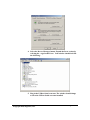
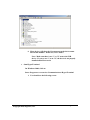
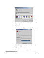
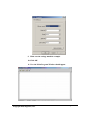
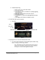
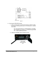
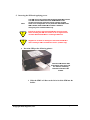
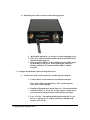
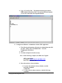
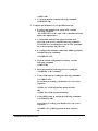
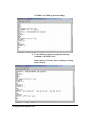
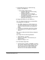
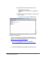
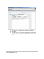
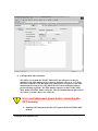
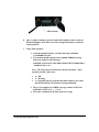
Application Note:
TT8540AN001
Skypatrol Evolution
GSM/GPRS Mobile Location Unit
Quick Start Guide
Revision 1.00a
Confidential and Proprietary Information –
© 2005 Skypatrol, LLC.
Do not duplicate without express permission from Skypatrol, LLC.
Version:
Date:
Status:
Document Control ID:
1.00a
09/08/05
Draft
TT8540AN001
General
All efforts have been made to ensure the accuracy of material provided in this
document at the time of release. However, the items described in this document
are subject to continuous development and improvement. All specifications are
subject to change without notice and do not represent a commitment on the part
of Skypatrol, LLC. Skypatrol, LLC. will not be responsible for any loss or
damages incurred related to the use of information contained in this document.
This product is not intended for use in life support appliances, devices or systems
where a malfunction of the product can reasonably be expected to result in
personal injury. Skypatrol, LLC. customers using, integrating, and/or selling this
product for use in such applications do so at their own risk and agree to fully
indemnify Skypatrol, LLC. for any damages resulting from illegal use or resale.
Copyright
Complying with all applicable copyright laws is the responsibility of the user.
Without limiting the rights under copyright, no part of this document may be
reproduced, stored in or introduced into a retrieval system, or transmitted in any
form or by any means (electronic, mechanical, photocopying, recording or
otherwise), or for any purpose, without the express written permission of
Skypatrol, LLC.
Skypatrol may have patents, patent applications, trademarks, copyrights or other
intellectual property rights covering subject matter in this document. Except as
expressly provided in any written license agreement from Skypatrol, the
furnishing of this document does not give you any license to these patents,
trademarks, copyrights or other intellectual property.
©2005, Skypatrol, LLC. All rights reserved.
Enabler is a registered trademark or trademark of Enfora, L.P. in the United
States.
Revision Control
Skypatrol Evolution GSM/GPRS MLU
Quick Start Guide
TT8540AN001
Date
Rev
Sep 8, 2005
1.00a
Author
L. Quiñones
Description
Draft
•
•
•
•
•
•
Objective:
The objective of this document is to provide the user with basic information on how to
configure the modem and verify communication with Skypatrol’
s UDPAPI test server.
Equipment Needed:
In this example the requirements are:
•
•
•
•
•
•
•
•
•
TT8540 Evolution GSM/GPRS MLU
Skypatrol Serial / Power cable Part number CBL027 or
a. Connector CBL028 or equivalent.
b. Wire minimum 20 AWG for 20 ft (max) for power.
c. DB9 female connector.
Power supply
GSM quad band antenna (P/N ANT027)
GPS 3.3v Active antenna (P/N ANT014)
Computer with one available Serial port or USB-to-serial converter
GSM/GPRS SIM with GPRS data enabled.
An APN (Access Point Name).
Username and Password, if GPRS is operating on a non-transparent network.
Note: If you don’
t know the name of the APN you need to use, please contact
your cellular network carrier for that information. Once you have acquired
this information, please complete Application Note TT8500AN019 –
GSM
Network Configuration Worksheet and keep this worksheet for future
reference.
References:
• TT8540PB001MAN –
User Manual
• TT8500PB001MAN –
User Manual
• TT8500AN019 –
TT8540AN001 (1.00a)
Copyright 2005, Skypatrol, LLC.
Skypatrol Evolution GSM/GPRS MLU Hardware
Skypatrol Evolution GSM/GPRS MLU Software
GSM Network Configuration Worksheet
Page 2 of 22
Procedures:
1. Configuring the computer and verifying correct communications.
Note: The following examples use Windows 2000 and HyperTerminal. Any
Terminal program should work, using the parameters in Step A.
a. Default Serial Parameters
1.
2.
3.
4.
5.
115200 baud rate
8 data bits
1 stop bit
No Parity
Flow Control = None
b. Determine which Com port to use
1. On older computers, there is usually a built in Com port. This is
normally Com1
2. If you are using a USB-to-serial converter, you will need to
determine which Com port it is installed on.
Note: If the USB-to-serial converter has not been installed, install the
necessary drivers per the instruction supplied by your USB-to-Serial
device. Then leave the device unplugged.
3. Open up the System Properties window. This is done through
the Control Panel > System or right-click on My Computer
and select Properties. Select the Hardware Tab. On Windows
2000 the screen looks like the following:
TT8540AN001 (1.00a)
Copyright 2005, Skypatrol, LLC.
Page 3 of 22
4. Select the Device Manager button. Expand the Ports section by
selecting the + sign beside Ports. Your window should look like
the following:
5. Plug in the USB-to-Serial converter. The window should change
to show the USB-to-Serial converter installed.
TT8540AN001 (1.00a)
Copyright 2005, Skypatrol, LLC.
Page 4 of 22
6. Most devices will show the Com port next to the device name.
Record this number. In this case, it is COM12.
Note: Make sure there is no “
!”
or “
X”
next to the USB
device. If you see an “
!”
or an “
X,”
the device is not properly
installed and will not work.
c. Start HyperTerminal
On Windows 2000, click on:
Start>Programs>Accessories>Communications>HyperTerminal
1. You should see the following screen.
TT8540AN001 (1.00a)
Copyright 2005, Skypatrol, LLC.
Page 5 of 22
3. Enter a name for the Connection. In this example, the Name is
Skypatrol Com1.
4. Click OK.
5. The next window that will appear is the Connect To window.
6. Change the Connect Using setting to the Com port that was
determined in Step B.
7. Click OK.
8. The next window is the Port Settings window.
TT8540AN001 (1.00a)
Copyright 2005, Skypatrol, LLC.
Page 6 of 22
9. Make sure the settings match the example.
10. Click OK.
11. Now the Main Program Window should appear.
TT8540AN001 (1.00a)
Copyright 2005, Skypatrol, LLC.
Page 7 of 22
d. Terminal Setup Testing.
1. Make sure the cursor is in the main window.
2. Start typing characters.
3. If all settings are correct, you should not see anything happening
in the main window.
4. Jumper Pins 2 and 3 together on the Serial connector.
5. Start typing characters.
6. You should now see what you are typing appearing in the main
window.
7. If this happens, the COM port is configured correctly.
2. EVOLUTION MLU panel descriptions
a. Front Panel
Figure 1
Power LED
b. Rear
GPS Status LED
Panel
SIM Slot
GSM status LED
Figure 2
3. Preparing the Power and Serial Communications Cable
a. Use a factory-built wiring harness with serial data option or build a wiring
harness according to the following schematic.
Note: The Ignition (pin 10) is Optional and is used to sense an
Ignition On event from the vehicle and will cause the modem to
reset if power is removed and reapplied to this input.
TT8540AN001 (1.00a)
Copyright 2005, Skypatrol, LLC.
Page 8 of 22
Figure 3
4. Connecting the GSM/GPRS antenna
a. Choose an antenna that is designed for the frequency band the in which
the modem is currently going to operate. The antenna jack is a standard
TNC Female.
Note: The antenna must have a nominal impedance of 50 Ohms.
The VSWR must be less than 2.0:1. System antenna gain should
be 0 –
2 dB for optimum performance.
b. Attach the GSM/GPRS antenna to Modem Ant jack.
GSM/ GPRS
Modem Antenna
Jack
TT8540AN001 (1.00a)
Copyright 2005, Skypatrol, LLC.
Page 9 of 22
5. Inserting the SIM and applying power
Note:
!
!
The SIM card is not provided with the EVOLUTION MLU device.
The SIM must be obtained from the GSM/GPRS service
provider and must be provisioned by the operator for data
and/or voice. Always take care to protect the SIM. Without the
SIM installed, EVOLUTION MLU modem is limited to
emergency voice communication only.
Ensure the power to the EVOLUTION MLU is disconnected
before inserting the SIM card. Failure to do so might result in
unusable EVOLUTION MLU or a damaged SIM card.
Skypatrol is not liable for damages to the EVOLUTION MLU
when inserting a SIM card inside the device. (TT8540 only).
a. Insert the SIM per the following picture:
Insert the SIM into the SIM
Slot with the notch going into
the slot first, and facing
toward the left side of the
modem.
1. Slide the SIM Lock Door to the left to lock the SIM into the
holder.
TT8540AN001 (1.00a)
Copyright 2005, Skypatrol, LLC.
Page 10 of 22
b. Install the power cable as shown in the following picture:
1. Hook up the modem to a 12 Vdc power source and apply power.
2. The Power LED should be solid red and the GSM Status LED
should start blinking green.
3. Once the modem attaches to the GSM network, the GSM Status
LED should go solid green. If the GSM Status LED stays
blinking, then there is a problem with the SIM or cellular
reception.
6. Configure the Modem to talk to the Skypatrol Server
a. Connect and verify Serial connectivity with the Skypatrol modem.
1. Connect the PC serial connector to the modem serial port.
Note: In the following instructions, <CR> means using the
Enter Key on the keyboard.
2. With HyperTerminal open, hit the Enter key. The modem should
respond with OK. If you do not see this response, double check
your connections and perform the serial loop back test again.
3. Type AT<CR>. The modem should respond with OK. If you
do not see the letters AT, send the following command to the
modem: ATE1<CR>
TT8540AN001 (1.00a)
Copyright 2005, Skypatrol, LLC.
Page 11 of 22
4. Type AT+CGSN<CR> . The modem should respond with its
IMEI number followed by OK If you get any different response,
you are not connected to the Skypatrol modem.
b. Configure the Modem to communicate with the UDP Application.
1. The following information will need to be obtained from the SIM
provider. Please refer to TT8500AN019 –
Network
Configuration Worksheet.
3. APN
4. Username and password (If necessary.)
Note: In the following examples, the SIM is for Cingular.
APN = isp.cingular
Username = [email protected]
Password = CINGULAR1
4. Reset the modem to factory defaults:
1. To restore the modem to factory defaults, send the
following command:
AT&F<CR>
2. To write current config to memory, send the following
command:
TT8540AN001 (1.00a)
Copyright 2005, Skypatrol, LLC.
Page 12 of 22
AT&W<CR>
3. To reset the modem, send the following command:
AT$RESET<CR>
5. Configure the Modem to Access the GPRS network.
1. To inform the modem of the proper APN, send the
following command:
AT+CGDCONT=1,”
IP”
,”
apn”
<CR> (substitute the letters
apn for the supplied apn.)
2. To inform the modem of the proper username and
password, (if necessary) send the following command:
AT%CGPCO=1,”
username,password”
,0<CR> (substitute
the correct username and password)
3. To configure the modem to enable auto GPRS registration,
send the following command:
AT$AREG=2<CR>
4. Store the current configuration to memory, send the
following command:
AT&W<CR>
5. Reset the modem by removing power or sending the
AT$RESET<CR> command.
6. Verify GSM status by sending the following command:
AT+CREG?<CR>
If everything is working, you should receive one of two
responses:
+CREG: 0,1 (GSM registered to home network)
OR
+CREG: 0,5 (GSM registered roaming.)
7. Verify GPRS status by sending the following command:
AT%CGREG?<CR>
If everything is working, you should receive one of two
responses:
%CGREG: 0,1 (GPRS registered to home network)
Or
TT8540AN001 (1.00a)
Copyright 2005, Skypatrol, LLC.
Page 13 of 22
%CGREG: 0,5 (GPRS registered roaming.)
8. Verify GPRS activation by sending the following
command: AT$NETIP?<CR>
If the response is non-zero, then everything is working.
Skip to Step 10.
TT8540AN001 (1.00a)
Copyright 2005, Skypatrol, LLC.
Page 14 of 22
9. If AT$NETIP returns all zeros, send the following
command: AT$CGEER<CR>
• There are three common responses:
• $CGEER: no PDP reject cause (Everything
should be working OK)
• $CGEER: requested service option not
subscribed (APN is incorrect or SIM has not
been enabled for data mode.)
• $CGEER: user authentication failed (username
and/or password is incorrect.)
10. Configure the modem to access the UDP Server.
Note: To configure the modem for server interoperability,
several things have to be addressed:
• Most GPRS configurations are Mobile Originate only.
The mobile modem must initiate a conversation with a
remote server before the remote server can talk to the
modem.
• IP addresses are dynamically assigned and can change.
• Some IP addresses are NAT and are non-routable IP
addresses.
These issues are addressed with the following configuration
commands.
The examples will use the following information:
• Modem ID/name = “
Evolution”
• Remote Server IP address = ###.###.###.### (your
public IP address)
• Remote Server IP port = 1721
11. Give the modem a unique name.
• Send the following command: AT$MDMID=”
Evolution”
This command, combined with the wakeup message, will
allow the server to associate a Public IP address with a
specific modem and create a window of opportunity
where the server can send commands to the modem
TT8540AN001 (1.00a)
Copyright 2005, Skypatrol, LLC.
Page 15 of 22
12. Configure the modem to talk with a specific server.
• Send the following command:
AT$FRIEND=1,1,”
###.###.###.###”
(your public IP
address)
13. Enable periodic messages (wakeup) to be sent to the server
every 60 seconds
• Send the following command: AT$WAKEUP=1,1
7. Verifying Server connectivity.
Note: For the following tests, Java Runtime must be installed on the
computer. (To install Java Runtime, please visit the Java website here:
http://www.java.com/en/download/manual.jsp)
a. Download the UDP application from the following URL:
http://www.toppdatasolutions.com/software/Evolution%20Series
b. Launch the GSMUDP.jar and you should see the following screen.
TT8540AN001 (1.00a)
Copyright 2005, Skypatrol, LLC.
Page 16 of 22
c. Enter the following command in the command/ data block: ATI
d. Select Write.
e. Verify that you see the following the modem response with Skypatrol,
L.P. If so, you have successfully configured the modem to talk with the
server.
TT8540AN001 (1.00a)
Copyright 2005, Skypatrol, LLC.
Page 17 of 22
8. GPS Operation and verification
The GPS receiver inside the EVOLUTION MLU provides power to the preamplifier in the GPS antenna (Active-style) by applying a power of 3.3 Volts to
the center conductor of the RF input to the GPS receiver. If a passive-style GPS
antenna must be used, please verify that it has a DC block installed in order to
prevent shorting to ground. The GPS antenna connector on the EVOLUTION
MLU model is an SMA female connector. The GPS antenna must be placed in an
area where it can have direct view of the sky.
!
User must disconnect power before connecting the
GPS antenna
a. Install the GPS antenna to the GPS ANT jack on the EVOLUTION MLU
modem.
TT8540AN001 (1.00a)
Copyright 2005, Skypatrol, LLC.
Page 18 of 22
GPS Antenna
b. After a couple of minutes, the GPS status LED should switch to solid red.
When this happens, the GPS receiver has enough information to track the
current position.
c. Verify GPS operation.
1. From the terminal window, send the following command:
AT$GPSRD=10<CR>
2. The modem should respond with a standard GPRMC message
that looks similar to the following:
$GPRMC,221223.00,A,3301.5080,N,09642.3857,W,000.0,000.0
,230805,05.9,E,A*19
Note: The entry shown in bold is the current GPS status. There
are three possible values here:
• A = OK
• V = Warning
• 9 = Skypatrol Specific response that GPS solution is not valid
and the last known GPS location is being substituted.
3. Here is an example of a GPRMC message without a GPS lock:
$GPRMC,221553.30,V,,,,,,,,,,N*7C
4. The same command can be used in the server app.
TT8540AN001 (1.00a)
Copyright 2005, Skypatrol, LLC.
Page 19 of 22
TT8540AN001 (1.00a)
Copyright 2005, Skypatrol, LLC.
Page 20 of 22