1
Bertec Force Plates
Version 1.0.0
March 2012
Bertec Corporation Bertec Force Plates
Copyright © 2009-2011 BERTEC Corporation. All rights reserved. Information in this
document is subject to change without notice. Companies, names, and data used in
examples herein are fictitious unless otherwise noted. No part of this document may be
reproduced or transmitted in any form or by any means, electronic or mechanical, for any
purpose, without express written permission of BERTEC Corporation or its licensees.
"Measurement Excellence", "Dominate Your Field", BERTEC Corporation, and their logos are trademarks of BERTEC
Corporation. Other trademarks are the property of their respective owners.
Printed in the United States of America.
Bertec’s authorized representative in the European Community regarding CE:
MIE Medical Research Ltd.
6 Wortley Moor Road, Leeds LS124 JF, United Kingdom
Phone: +44-113-279-3710, Fax: +44-113-231-0820
ii
Bertec Corporation Bertec Force Plates
SOFTWARE LICENSE AGREEMENT AND LIMITED WARRANTY
This License Agreement is between you (“Customer”) and Bertec Corporation, the author of the Bertec Workbook software and governs your use of the program, example results, and documentation (all of which are
referred to herein as the "Software").
THIS IS A LEGAL AGREEMENT BETWEEN YOU (EITHER AN INDIVIDUAL OR AN ENTITY), THE END USER, AND BERTEC CORPORATION. IF YOU DO NOT AGREE TO THE TERMS OF THIS
AGREEMENT, PROMPTLY RETURN THE DISKS AND ACCOMPANYING ITEMS TO BERTEC CORPORATION, AND/OR DO NOT DOWNLOAD THE SOFTWARE FROM OUR WEB SITE AND/OR
DO NOT INSTALL THE SOFTWARE.
1. Grant of License
Bertec grants to you a non-exclusive, non-transferable license, without right to sublicense, distribute or modify, for you and your employees to use the enclosed software and related documentation (collectively the
"Product" or the “Software”) as delivered by Bertec only at one location for the testing and evaluation. If the terms of this license agreement are violated, Bertec immediately terminates said license and the customer is
subject to the liability of any harm done to Bertec Corporation.
2. Title
The product is copyrighted by Bertec. Bertec retains all rights, title, and ownership of the Product and all subsequent full or partial copies and derivatives of the Product, made by you or Bertec, including translations,
compilations, partial copies, modifications, updates and know-how in connection there with, regardless of the form or media in or on which the same may exist. This license is not a sale of the Product or any copy or
derivative. You shall have no right to reproduce any full or partial copies of the Product. You agree not to take any steps, such as reverse assembly or reverse compilation, to derive a source code equivalent of any
software contained in the product. You also agree to destroy licensed data in all forms upon termination of said license or receipt of released program code.
3. Confidentiality
You agree that the product, and other information, technical data, or know-how (including documentation) related to the Product (including the existence of the product and the results of use or testing), shall be
considered Confidential Information of Bertec. You agree to protect the confidentiality of all Confidential Information of Bertec, and not to disclose the Confidential Information to any other party without the written
permission of Bertec. Unauthorized use or disclosure of the Product may cause irreparable harm to Bertec. You agree promptly to report any unauthorized use or disclosure to Bertec.
4. Warranty of Functionality
Bertec hereby represents and warrants that Bertec is the owner of the Product or otherwise has the right to grant to you and your employees the rights set forth in this Agreement. THE PRODUCT IS PROVIDED "AS
IS". THERE ARE NO WARRANTIES UNDER THIS AGREEMENT, AND BERTEC DISCLAIMS ANY IMPLIED WARRANTY OF MERCHANTABILITY OR FITNESS FOR PARTICULAR PURPOSE. In the
event of any breach or alleged breach of this warranty, you shall promptly notify Bertec and return the Product to Bertec at your expense. Your sole remedy shall be that Bertec shall correct the Product so that it
operates according to the warranty. This warranty shall not apply to the Product if modified by anyone or if used improperly or with, on, in an operating environment not approved by Bertec.
5. Limitation of Liability
IN NO EVENT SHALL BERTEC BE LIABLE FOR ANY LOSS OF PROFITS, LOSS OF USE, SPECIAL, INCIDENTAL OR CONSEQUENTIAL DAMAGES PURSUANT TO THIS AGREEMENT. Bertec shall
not be responsible for, and shall not pay, any amount of incidental, consequential or other indirect damages, whether based on lost revenue or otherwise, regardless of whether Bertec was advised of the possibility of
such losses in advance. In no event shall Bertec's liability hereunder exceed the amount of license fees paid by you, regardless of whether your claim is based on contract, tort, strict liability, product liability or
otherwise.
6. Product Maintenance
During the Warranty Period, Bertec shall provide to you any new, corrected or enhanced version of the Product as created by Bertec. Such enhancement shall include all modifications to the Product which increase the
speed, efficiency or ease of use of the Product, or add additional capabilities or functionality to the Product, but shall not include any substantially new or rewritten version of the Product. These updates will require
Internet Access to our web site to automatically validate your License Key and provide update support.
After expiration of the Warranty Period, you may continue to receive maintenance support. The charge for such optional maintenance support shall be Bertec's regular list price for maintenance and support for the
Product as published from time to time by Bertec. You will need to notify Bertec in writing if you desire to receive optional maintenance. If you fail to take optional maintenance and later elect to receive it, Bertec
reserves the right to charge you their standard maintenance fees for the period of the lapse in maintenance. Bertec may elect to discontinue maintenance at any time upon notice to you, and refund of any then unearned
maintenance fees.
7. Proprietary Rights Exclusion
Bertec makes no representation or warranty that the Product, or products developed using the Product, do not infringe any proprietary rights of any third parties. You shall assume sole responsibility for any such
infringement.
8. Indemnification
You hereby agree to indemnify, defend and hold Bertec harmless from and against any and all claims, actions, suits, liabilities, judgments, losses, damages, attorneys' fees and other expenses of every nature and
character by reason of this Agreement or use by you of products utilizing the Product.
9. Export Restrictions
You shall not export, directly or indirectly, any Product or products developed using the Product to any country for which the laws of the United States or the regulations of any U.S. agency requires an export license
or other governmental approval, without first obtaining such license or approval. You shall strictly comply with all such restrictions. You agree to indemnify and hold Bertec harmless against all losses, damages,
penalties, or causes of action resulting from a violation of this Section.
10. Anti-Piracy and License Activation
You must not engage in the distribution of pirated software or hardware. Use of the Product may be limited to the first 14 days after the end user first use the software, unless the end user activates the Product, as
described in and by the Product. Certain Bertec products may use technological measures for copy protection. In that event, you will not be able to use the Product if you do not fully comply with the Product
Activation Procedures. Product Activation will take place during initial launch of the product, installation on a different system, or replacement of the installed operating system or certain hardware changes.
11. Governing Law
The validity, performance, construction and interpretation of this Agreement shall be governed by laws of the state of Ohio, United States of America, excluding its conflicts of laws rules, as applied to agreements
entered into in Ohio between Ohio residents.
12. High risk activities
The software and/or hardware supplied by Bertec Corporation is not fault-tolerant and is not designed, manufactured or intended for use or resale as on-line control or equipment in hazardous environments requiring
fail-safe performance in which the failure of software and/or hardware could lead directly to death, personal injury, or severe physical or environmental damage ("high risk activity"). Bertec Corporation and its
suppliers specifically disclaim any express or implied warranties of fitness for high risk activities.
Should you have any questions concerning this Agreement, please write to:
Bertec Corporation, 6171 Huntley Road, Suite J, Columbus, Ohio 43229
iii
Bertec Corporation Bertec Force Plates
TABLE OF CONTENTS
Introduction __________________________________________________________________________ 6
Definitions, Acronyms, and Abbreviations __________________________________________________ 7
Installation and Setup __________________________________________________________________ 8
Mounting the Force Plate _____________________________________________________________________ 8
Without a Mounting Plate_____________________________________________________________________ 9
Using a Mounting Plate _______________________________________________________________________ 9
Mounting Plate assembly instructions ____________________________________________________________________ 10
Cables and Amplifier Connections ________________________________________________________ 12
Data Acquisition and Load Calculations ___________________________________________________ 13
Analog Data Acquisition _____________________________________________________________________ 13
Analog Auto Zero _____________________________________________________________________________________ 13
Calculating Load Values______________________________________________________________________ 14
Calculation of the Point of Application of Force and Couple _________________________________________ 15
Load Computation Example __________________________________________________________________ 16
Change of Coordinate System _________________________________________________________________ 18
Change of Reference System__________________________________________________________________ 19
Technical Specifications ________________________________________________________________ 21
Force Plates _______________________________________________________________________________ 22
Rated Load ________________________________________________________________________________ 22
Natural Frequency __________________________________________________________________________ 22
Anchor Locations ___________________________________________________________________________ 24
Amplifiers and Signal Converters_________________________________________________________ 25
AM6500 Digital Signal Converter ______________________________________________________________ 25
AM6501/AM6504 Analog Amplifier ____________________________________________________________ 26
AM6800 Dual Output, Adjustable Gain Amplifier _________________________________________________ 27
General Specifications _______________________________________________________________________ 28
Troubleshooting ______________________________________________________________________ 29
Customer Support_____________________________________________________________________ 30
Document Revision History _____________________________________________________________ 31
iv
Bertec Corporation Bertec Force Plates
LIST OF FIGURES
Mounting plate with eyebolts...........................................................................................................................................................10
Mounting plate with force plate .......................................................................................................................................................10
Force and signal scale factors...........................................................................................................................................................14
Coordinate system for load measurements ......................................................................................................................................15
Force and Couple equation ...............................................................................................................................................................15
Force F and the point of application of the force..............................................................................................................................16
The ground reaction load..................................................................................................................................................................19
Force plate anchor locations.............................................................................................................................................................24
AM6500 Signal Converter .................................................................................................................................................................25
AM6500 Digital Signal Converter connections..................................................................................................................................25
AM65xx analog amplifier..................................................................................................................................................................26
AM65XX series connections ..............................................................................................................................................................26
Gain switch settings for the AM6504................................................................................................................................................26
AM6800 Dual output adjustable gain amplifier ...............................................................................................................................27
AM6800 amplifier .............................................................................................................................................................................27
Pin configuration for the standard analog 15-pin connector ...........................................................................................................28
v
Bertec Corporation Bertec Force Plates
INTRODUCTION
Bertec's product line of force plates have been specifically designed for gait, balance, sports and other static and dynamic
analyses. Through the use of strain gauge technology, innovative design, and quality manufacturing, Bertec's force plates are
well suited for both static and dynamic applications. Each force plate consists of a number of strain gauged load transducers and
a built-in digital pre-amplifier for signal conditioning. Bertec force plates come in a variety of sizes and associated load ranges to
suit different application needs. The 4550, 4060 and 4080 series plates have been designed specifically for the demands of
clinical and research gait analysis, whereas 6090, 9090 and 6012 series force plates are well suited for the rigors of sports and
other dynamic biomechanics, ergonomics and industrial research. The rugged honeycomb technology used for the production
of the tops and bases ensure enhanced dynamic measurement characteristics while keeping the overall weight to a minimum.
All of the models can be portable in that they do not require separate mounting plates, and can be moved from one location to
another. Smaller models, like 4550 and 4060, also have non-portable versions to be used with a mounting plate. Years of
experience in force plate design enables Bertec to customize all models to suit customers' requirements. Most of the models,
for example, can be retrofitted to be waterproof or the sizes of standard models can be modified for specific applications.
Bertec force plates are six-component load transducers, which measure the three orthogonal components of the resultant force
acting on the plate and the three components of the resultant moment in the same orthogonal coordinate system. The point of
application of the force and the couple acting on the plate can be readily calculated from the measured force and moment
components.
Bertec force plates use a state-of-the-art 16-bit digital technology for signal acquisition and conditioning. This technology makes
the use of calibration matrices obsolete, since each plate comes with the calibration matrix already digitally stored on it.
External amplifiers to be used with force plates provide the user with three signal output alternatives: digital, analog, or dual
digital/analog outputs. The digital signal output can be directly plugged into the standard USB port of a personal computer
without the requirement of an additional PC card for analog-to-digital (A/D) signal conversion. This plug-and-play technology
allows a simpler installation procedure in a minimum amount of time, and allows the digital signal to be used on PC systems that
would not otherwise be able to use a PC signal conversion card, such as a laptop computer. The digital data acquisition
software, Bertec Digital Acquire 4, provided with the force plates as a standard item, enables the user to collect data quickly
without the need of additional custom designed software. Software libraries and device drivers are available from Bertec so that
the user can write his/her own digital data acquisition software.
The analog output of the force plates can be fed into an A/D board so that data can be collected using conventional techniques.
Depending on application, signal amplification can be performed for analog output using external amplifiers. External amplifiers
are either fixed gain (factory set according to customer requirements) or adjustable gain (seven adjustable gains). These
amplifiers enable the user to establish a trade-off between the measurement range and resolution of the force plates.
The wide variety of force plates in Bertec's product line can be used with any type of motion analysis system ranging from
camera-based systems using passive markers to systems with active markers or magnetic sensors. For example, the 4060-NC
model is a non-conductive plate specifically designed to be used in environments requiring measurement of magnetic fields.
6
Bertec Corporation Bertec Force Plates
DEFINITIONS, ACRONYMS, AND ABBREVIATIONS
Balance plate: a Bertec device that measures pressure and movement that is optimized for balance diagnostics.
Force plate: a Bertec device that measures pressure and movement.
Center of Pressure (CoP): The point on the surface of the platform through which the ground reaction force acts. It corresponds
to the projection of the subject's center of gravity on the platform surface when the subject is motionless.
AM6500: a digital signal converter that connect a force plate to a USB cable.
AM65xx: an analog amplifier that connects a force plate to an analog device.
AM6800: a dual output, adjustable gain amplifier that connects a force plate to an analog device or USB cable.
7
Bertec Corporation Bertec Force Plates
INSTALLATION AND SETUP
All Bertec force plates are pre-assembled in the factory. Therefore, they are ready to be installed and used by either mounting
or placing them on the floor depending on the force plate design, and connecting the cables.
Do not attempt to disassemble the force plate, damage can occur to the transducer components or electronics.
The Limited Warranty is void if the force plate or any of the accessories are disassembled without the authorization
of Bertec.
Unsecured cables pose a serious tripping and injury hazard, in addition to possibly damaging the equipment. Make
sure that all cables are secured using tie downs, tape, or a cable raceway.
MOUNTING THE FORCE PLATE
To obtain a high quality measurement from Bertec force plates, they should be installed in a way that is suitable for the type of
measurement to be performed. The floor and structure underneath should be prepared to be as rigid as possible in order to
minimize any vibrations. Bertec force plates are very sensitive devices, and they will pick up any vibration coming from the
support structure. An additional consideration is the flatness of the mounting surface. Bertec force plates are designed to work
accurately on uneven surfaces. However, overstraining them during installation or while in use might introduce errors into the
measurements.
Fixing the force plate to a surface is optional. If the application for the force plate involves high horizontal forces, which might
cause the plate to slide, then it is strongly suggested that the plate be anchored using the mounting locations provided on the
feet. Depending on the model used, an additional mounting plate might be necessary to fix the force plate to the floor.
For effective use, the top surface of the force plate should be at the same level as the rest of the floor. For this purpose, a pit
can be made in which the plate is mounted. Alternatively, a raised walkway can be used with the top surface of the walkway at
the same height as the top of the force plate. No matter what methodology is used, remember to leave room for the output
cable and make sure that the force plate does not touch any surrounding structure as this might result in measurement errors. A
gap of 1-2 mm (0.04"-0.08") between the force plate and surrounding floor will be appropriate. The following practical
considerations will be helpful during installation. If you need additional assistance, please contact Bertec Corporation.
8
•
The pit should be deep enough to accommodate the height of both the force plate and mounting plate. Leave an
additional ⅛"-¼" space for leveling tolerances.
•
The height of a standard mounting plate is ¾" (19.05 mm).
•
The size of the pit should be large enough to take future expansion plans into account, such as adding more force
plates or other equipment.
Bertec Corporation Bertec Force Plates
•
•
Allow at least 8" (20 cm) free space around the force plate so that the output cable can be positioned and routed
without placing undue stress on the cable or connectors, and the wrench to tighten the mounting bolts can be
operated easily.
Incorporate a conduit into the construction plan so that the output cable will run under the floor. Make the conduit
large enough for the cable connector to pass through. The minimum diameter for a straight conduit should be 1¾" (45
mm). If there are bends and corners in the conduit, then the recommended diameter is 3 inches (75 mm).
WITHOUT A MOUNTING PLATE
Bertec force plates may be used on any type of surface. When used on a hard, non-flat surface, shimming is required to prevent
rocking of the plate (plain paper works fine for shimming small gaps up to 1/32"). When mounting to a concrete surface, Bertec
recommends using threaded anchors permanently affixed to the concrete floor. The standard bolts to be used with force plates
are of the size ⅜" – 16 UNC (or M8 – 1.25 for European customers). For the exact locations of the anchor points for different
force plate models, please refer to Technical Specifications - Force Plates. Finally, the area where the plate is going to be
mounted should be clean.
Caution should be taken when using unfixed force plates. Large shear forces may cause an unattached plate to
move on the surface, which can be dangerous for both the subject and any by-standers. Bertec recommends
avoiding the use of unfixed plates in these situations.
If you are not sure about the flatness of the mounting surface, tighten the anchoring bolts as little as possible to
avoid bending the base of the force plate. Make sure that the only contact is between the feet and mounting
surface, and the entire surface below the feet is properly shimmed.
USING A MOUNTING PLATE
Standard Mounting Plates are ¾" (19 mm) thick and have the same dimensions as the force plate. The Mounting Plates come
with pre-tapped holes that mach the anchor locations on the feet of the force plate, along with leveling hardware. Typically, the
Mounting Plate is rigidly affixed to the floor with a high strength epoxy. Then, the plate is mounted onto the mounting plate via
four hexagonal cap screws of size ⅜" – 16 UNC (or M8 – 1.25). The following installation hardware is provided with the
Mounting Plate:
•
High Strength Epoxy – to glue the Mounting Plate
•
Trowel and Putty Knife – to spread the epoxy on the floor
•
Spirit or Water Level – to adjust the levelness of the force plate
•
Hexagonal Allen Key – to adjust the set screws on the Mounting Plate
•
Eye Bolts – to lift the Mounting Plate
•
Hexagonal Cap Screws – to attach force plate to the Mounting Plate.
9
Bertec Corporation Bertec Force Plates
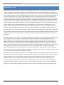
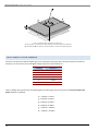
MOUNTING PLATE ASSEMBLY INSTRUCTIONS
Please read all instructions below before installing the Mounting Plate.
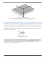
Place the mounting plate on concrete floor in desired location. Ensure that the setscrews on the Mounting Plate are not
touching the floor at this point (depending on the size of the Mounting Plate there may be four (4) or more set screws). The
provided eyebolts may be used in the force plate mounting locations to make lifting of the Mounting Plate easier.
Mounting plate with eyebolts.
The adjustable setscrews are used to level the Mounting Plate.
Assemble the force plate to Mounting Plate using outer corner holes with provided bolts (⅜"–16 UNC or M8–1.25) and washers.
Level the force plate using the outer accessible setscrews (the ones closer to the edge of Mounting Plate). The sprit or water
level provided can be used on top of the force plate if necessary. Make sure that Mounting Plate is lifted from the floor at least
1/16–1/8 inches (2–3 mm) to allow room for the glue. If the force plate is to be mounted in a pit, which does not provide easy
access to the setscrews, the Mounting Plate can be leveled first. However, make sure that the top of the force plate is flush with
the surrounding floor before proceeding further.
Mounting plate with force plate
The Mounting Plate can be leveled while the force plate is mounted on it.
Mark the outer perimeter of the Mounting Plate on the floor.
Disassemble the force plate from the Mounting Plate, leaving the Mounting Plate in position.
10
Bertec Corporation Bertec Force Plates
Adjust any unadjusted setscrews in the middle of the Mounting Plate to just touch floor. When working with large Mounting
Plates, making sure that the plate has not sagged in the middle. If necessary, further adjust with the central set screws.
Remove the Mounting Plate. Make sure that the setscrew adjustments do not change.
Mix the two parts of the epoxy adhesive (1:1 ratio) in the plastic bucket provided. Make sure that the epoxy and the hardener is
thoroughly mixed (about 5 minutes by hand). The working life of the epoxy is 30 minutes.
Spread the epoxy on the floor, within the marked area, using the notched trowel provided. The notches of the trowel will help
form "hills and valleys" of epoxy so that when Mounting Plate is placed back on it, the epoxy has room to spread.
Relocate the Mounting Plate back to the marked area.
Allow the epoxy adhesive to cure overnight before assembling force plate.
Mount the force plate to the Mounting Plate using the supplied screws (⅜" – 16 UNC or M8 – 1.25) and washers.
11
Bertec Corporation Bertec Force Plates
CABLES AND AMPLIFIER CONNECTIONS
After the force plate is mounted onto the floor, the next step in the installation is making the cable connections with external
amplifiers and the computer. The standard output of Bertec force plates is an 8-pin male round receptacle. The standard output
cable is 10 m (33') long, has an 8-pin round female connector at the force plate end, and a 9-pin male D-Sub connector at the
other end.
To connect the force plate output cable to the force plate:
• Identify the 8-pin female round connector on the force plate output cable.
• Match the keys of the plug and receptacle.
• Push in the connector and rotate (about ¼ turn) clockwise until the two fully engage and lock.
Depending on the configuration of the system, the 9-pin male connector plugs into an external amplifier or signal converter.
Analog output from Bertec signal conditioning amplifiers is a standard 15-pin female D-Sub connector. The output of the
external amplifier connects to the computer used for data acquisition. For analog outputs an additional A/D signal conversion
card on the PC is necessary. Digital output of the amplifiers plugs directly into the USB port of the computer using the USB cable
provided with the system. Pin configuration for the analog output is given the General Specifications section.
Additional analog output cables to connect amplifiers to A/D boards are available from Bertec Corporation. One end of these
cables is always a 15-pin male D-Sub connector, which plugs into the amplifier. The other end is manufactured depending on
specific customer order (e.g. BNC, bare wire leads, etc.).
The electrical network that is used to supply power to the data acquisition systems and force plates should be
properly grounded. Poor grounding is a common source of signal noise in electronic systems. Although all Bertec
force plates and amplifiers carry the CE mark of the European Union to ensure high signal quality, improper
grounding and external power sources might degrade signal characteristics.
12
Bertec Corporation Bertec Force Plates
DATA ACQUISITION AND LOAD CALCULATIONS
All Bertec products use a novel 16-bit digital technology for signal acquisition and conditioning. The output signal of the load
transducers are already digitized and conditioned in the force plate by using state-of-the-art electronics developed by Bertec
Corporation. With this new technology the output signal has a very high signal-to-noise ratio, which means increased sensitivity
and accuracy for the force plates. In addition, the digital technology makes the use of calibration matrices obsolete, since each
plate comes with the calibration matrix already digitally stored on it. Depending on the configuration, the system provides the
user with a digital, analog, or dual digital/analog output.
The digital output of the system is always in the form of calibrated data in their respective units selected by the user (N and
N•m, or lb and lb•in). The analog output requires an additional scaling depending on the external amplification used in data
acquisition.
ANALOG DATA ACQUISITION
The output of the force plate is in the form of a 16-bit digital signal. External digital-to-analog (D/A) converters are used in order
to obtain analog output to be used in conventional data acquisition systems. The D/A converters are also analog amplifiers with
either a fixed (65XX series) or adjustable gain (6800 series) setting (for a detailed description of amplifiers please refer to the
Amplifiers and Signal Converters section). The pin configuration for the 15-pin analog output is given in the General
Specifications section.
Before starting to collect data, make sure that the cables from the force plate to the amplifier, and from the
amplifier to the PC is properly connected. Power to the amplifier should be connected, and the amplifier should
be turned on (in 6800 series only).
The force transducer system reaches thermal stability in about 5 minutes. Therefore, always allow the equipment
to warm up at least for 5 minutes before collecting data.
ANALOG AUTO ZERO
All analog amplifiers are equipped with an "Auto Zero" button. This button allows zeroing offset loads up to full scale. This
functionality can be used to remove tare weight of equipment such as a chair or a step, placed onto the force plate as part of
the measurement protocol. When the amplifier is first turned on, of the two green lights next to the auto zero button, only the
bottom one will be on, confirming that the amplifier is powered. This indicates that zero has not been set yet. Simply press and
release the auto zero button in order to zero the bridges on the amplifier. When zero is set, both lights next to the auto zero
button will be on.
For the variable gain 6800 series amplifiers, the auto zero button is next to the power switch on the front panel. For the fixed
gain amplifiers (65XX series), it is located next to the 15-pin output connector.
Note that auto zeroing sets all channels to near zero. True zeroing should be done by software at the time of data
collection, by subtracting a baseline reading from the collected data.
13
Bertec Corporation Bertec Force Plates
The analog data acquisition procedure can be summarized as follows:
•
Check all the cables, and make sure that they are properly connected.
•
Turn on the amplifiers and allow the system to warm up at least for 5 minutes.
•
For the 6800 series variable gain amplifiers, set a proper gain value for the data channels using the gain switch on the
front panel of the amplifier.
•
Press the auto zero button in order to remove any offset load on the force plate.
•
Collect analog data using software. Remember to remove a baseline reading from the signals using software in order to
set the signal mean values to true zero.
CALCULATING LOAD VALUES
Each force plate is calibrated individually and the calibration matrix is stored digitally in the force plate. Therefore, the analog
output from the amplifier provides full-scale calibrated output (±5 V) per rated load range of the attached force plate. The
voltage output of each channel is a scaled form of the load in the units of N and N•m for the forces and moments respectively.
The scale factor for each channel for a gain of unity is given in the product data sheet supplied with the transducer. The force
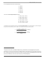
and moment values are calculated by multiplying the signal values with corresponding scale factors, as given in the following
equation:
Fx = C 1 ⋅ S 1
Fy = C 2 ⋅ S2
Fz = C 3 ⋅ S 3
M x = C4 ⋅ S4
M y = C 5 ⋅ S5
M z = C 6 ⋅ S6
Force and signal scale factors
where, F's and M's are the force and moment components in the force transducer coordinate system (Coordinate system for
load measurements figure, next page), and S's are the output signals corresponding to the channels indicated by their
subscripts, in volts, divided by the respective channel gain. The origin of the coordinate system is centered on the top surface of
the force plate (see Coordinate system for load measurements and Force and Couple equation, next page). The standard
coordinate system is such that the positive y-direction points forward; x-axis is to the left when looking in the y-axis direction;
and the z-axis is defined downwards by the right hand rule.
14
Bertec Corporation Bertec Force Plates
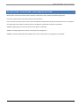
Coordinate system for load measurements
The center of the coordinate system is at the inner corner of the arm block with y-axis forward,
x-axis to the left (pointing inwards looking from behind), and z-axis downward.
CALCULATION OF THE POINT OF APPLICATION OF FORCE AND COUPLE
A load system acting on a treadmill belt can be completely described by the six load components (i.e. the three force and three
moment components) calculated from the Force and signal scale factors equation. Alternatively, the same information can be
given as the three force components, the point of application of the force vector (xp, yp), and a couple (sometimes also referred
as "torque" or "free moment") acting on the force plate. The point of application of the force and the couple are calculated from
the force and moment components as:
xp =
yp =
− h ⋅ Fx − M y
Fz
− h ⋅ Fy + M x
Fz
Tz = M z − x p ⋅ Fy + y p ⋅ Fx
Force and Couple equation
Where xp and yp are the coordinates of the point of application for the force (i.e. center of pressure) on the treadmill belt; h is
the thickness above the top surface of any material covering the force plate (see the Coordinate system figure, above), and Tz is
the couple acting on the force plate. Note that the thickness h, shown in the figure on the next page, is to be entered as a
positive number in the Force and Couple equation above.
15
Bertec Corporation Bertec Force Plates
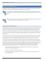
Force F and the point of application of the force
The force plate is covered with a layer of floor covering, which has a thickness
h . The thickness h is entered as positive number in Force and Couple equation
LOAD COMPUTATION EXAMPLE
Consider a case where the external amplifier gain is set to 10 (note that the gain value is always the same for all of the six
channels). If, at an instant in time, the amplifier voltage outputs for the six channels are:
CHANNEL
1
2
3
4
5
6
OUTPUT, V
-1.450
2.235
4.765
3.095
-0.575
-1.016
Then, by dividing each output by the corresponding gain, the output signal values to be used in the Force and signal scale
factors equation are obtained:
S1 = -1.450/10 = -0.145 V
S2 = 2.235/10 = 0.2235 V
S3 = 4.765/10 = 0.4765 V
S4 = 3.095/10 = 0.3095 V
S5 = -0.575/10 = -0.0575 V
S6 = -1.016/10 = -0.1016 V
16
Bertec Corporation Bertec Force Plates
1
Let us use hypothetical scale factors, in N/V and N•m/V :
C1 = 1000 N/V
C2 = 1000 N/V
C3 = 1500 N/V
C4 = 300 N•m/V
C5 = 300 N•m/V
C6 = 250 N•m/V
Then from the Force and signal scale factors equation:
Fx = 1000 • (-0.145) = -145.0 N
Fy = 1000 • (0.2235) = 223.5 N
Fz = 1500 • (0.4765) = 714.8 N
Mx = 300 • (0.3095) = 92.9 N•m
My = 300 • (-0.0575) = -17.3 N•m
Mz = 250 • (-0.1016) = 25.4 N•m
To calculate the point of application of the force, the Force and Couple equation is used. Assuming there is a 5 mm covering on
the top surface of the transducer, then h = 0.005 m. The coordinates of the Center of Pressure will be:
xp =
(− 0.005) ⋅ (− 145.0) + 17.3 = 0.025 m
714.8
(− 0.005) ⋅ (223.5) + 92.9 = 0.128 m
yp =
714.8
Note that if the results are needed in English Units, an alternative to converting them at the end of
calculations is to convert the scale factors to English Units by converting the first three factors from N/V to
lb/V, and the last three factors from N•m/V to ft•lb/V. This can be done by multiplying the first three scale
factors by 0.2248 lb/N, and last three scale factors by 0.7376 (ft•lb)/(N•m).
1
17
Bertec Corporation Bertec Force Plates
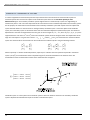
CHANGE OF COORDINATE SYSTEM
In numerous applications measurement protocols require that the forces and moments be measured with respect to a
coordinate system other than the force plate's local coordinate system shown in the Coordinate System for Load
Measurements figure. This secondary coordinate system might be that of a motion analysis system or it might belong to
another force plate. In such a case the components of force and moment vectors should be expressed in this secondary system.
For this purpose, the exact location and orientation of the secondary coordinate system with respect to the force plate local
system should be known. For the case shown in the figure below, coordinate system 1 is the force plate's local coordinate
system, and a secondary system 2 is located so that its axes are rotated and displaced in 3-dimensional space. The rotational
displacement is such that the angle between axes are given in terms of angles θ11, θ12, … θ33, where θij (i=1, 2, 3; j=1, 2, 3) is the
angle between the unit vectors u1i and u 2j of the two coordinate systems shown in the figure below. The displacement of the
r
r
origin of 1 with respect to 2 is given as the vector r = {r1 r2 r3 }, where r1, r2 and r3 are measured in the second coordinate
r
system. The measured forces and moments can be transformed to coordinate system 2 using the following relations:
F 2
F 1
x2
x1
Fy = [T ] ⋅ Fy
2
1
F z
F z
M 2
M 1
F 2
x2
1x r x2
M y = [T ] ⋅ M y + r × Fy
2
1
2
M z
M z
F z
Where superscript "1" denotes measured quantities, superscript "2" indicates the same quantities expressed in coordinate
system 2, and [T] is a transformation matrix computed using the θij values described above. The elements of the 3x3
transformation matrix are the direction cosines of the coordinate axes arranged as:
cos θ11
[T ] = cos θ21
cos θ31
cos θ12
cos θ22
cos θ32
cos θ13
cos θ23
cos θ33
r
u32
r
u31
r
u11
r
u22
rr
r
u21
r
u12
Coordinate system 1 is a force plate's local coordinate system in which the loads are measured. The secondary coordinate
system is displaced and rotated with respect to the first in 3-dimensional space.
18
Bertec Corporation Bertec Force Plates
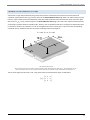
CHANGE OF REFERENCE SYSTEM
Assume that in a gait analysis laboratory the ground reaction forces and moments are measured in the force plate local
coordinate system with the axes xf, yf, and zf as shown in the Ground Reaction Load image, below. The motion analysis system,
however, requires these loads to be computed in a laboratory fixed coordinate system located at the corner of the force plate
with the axes xL, yL, and zL oriented as given in the Ground Reaction Load image. The x and z-axes of both coordinate systems
are pointing in opposite directions rotated by 180˚, and the y-axes are parallel to each other. The origins are displaced by 20 cm
r
in x-direction, and 30 cm in y-direction. For such an arrangement the vector r will be {0.2 0.3 0} m. Since the corresponding
coordinate axes are parallel to each other we have the following values for the angles θ:
θ11 = 180˚, θ22 = 0˚, θ33 = 180˚
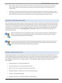
The ground reaction load
This is measured in the force plate's local coordinate system denoted by the subscript "f". The components of the
force and moment vectors are transferred to the laboratory coordinate system indicated by the subscript "L".
The rest of the angles are either 90˚ or -90˚. Using these values the transformation matrix is calculated as:
− 1 0 0
1 0
0 0 − 1
[T ] = 0
19
Bertec Corporation Bertec Force Plates
Using the hypothetical measured values calculated in Example 1 above in Equations 3 and 4, we get:
F 2 − 1 0 0 − 145.0 145.0
x2
Fy = 0 1 0 ⋅ 223.5 = 223.5 N
2 0 0 − 1 714.8 − 714.8
F z
M 2 − 1 0 0 92.9
x2
M y = 0 1 0 ⋅ − 17.3 +
2 0 0 − 1 25.4
M z
0.2 145.0
0.3 × 223.5
0 − 714.8
M 2 − 307.3
x2
M y = 125.7 N ⋅ m
2 − 24.2
M z
20
Bertec Corporation Bertec Force Plates
TECHNICAL SPECIFICATIONS
Bertec force plates are designed to cover a wide range of technical specifications to meet the needs of clinicians and researchers
from a variety of fields. Standard force plates are available in different sizes and load capacities, which can further be
customized depending upon the requirements of the measurements to be performed. The popular 4550, 4060 and 4080 series
are the gold standard for gait analysis studies, while larger sizes such as the 6090, 9090 and 6012 series are well suited for the
rigors of sports, ergonomics, industrial, and other dynamic biomechanical applications.
The measured signals from strain gauge based force transducers are amplified, filtered, and digitized in the force plate, which
minimizes signal degradation due to external noise sources during analog signal transportation. The output of the force plate is
a 16-bit single channel, serial, digital signal, which can be transported over very long distances without any loss of quality. The
digital output can be directly connected to the USB port of the computer, or it can be fed into an external amplifier and
converted into six individual analog signals to be connected to an A/D card. All the electronics of the force plates are designed
and developed by Bertec Corporation. Analog and digital external amplifiers are designed so that measurement load range and
sensitivity can be selectively optimized.
Deciding on a particular model is not a trivial task, and requires a careful evaluation of the needs and technical specifications of
the force plates. Type of studies to be performed, available space, other equipment to be used with the force plate, and
available budget are among the many important deciding factors in selecting force plates. Furthermore, depending on the
application a suitable force plate – amplifier combination should be selected.
This chapter provides the basic information about the mechanical and electrical properties of the force plates and amplifiers. If
you have additional questions, please contact Bertec Corporation.
21
Bertec Corporation Bertec Force Plates
FORCE PLATES
Basic technical specifications for the particular force plate that you have are given on the data sheet provided with your force
2
plate. The table below gives the specifications for standard configuration force plates .
The technical specifications for the particular force plate you have might be different than those given in the table on the next
page. Please check the product specific data sheet provided with your order.
MODEL
4060-08
4060-10
4060-15
4550-08
4060-NC
4080-10
4080-15
6090-15
9090-15
6012-15
SIZE (mm)
L
W
600
400
508
600
464
400
800
400
900
900
1200
600
900
600
H
83
100
150
83
100
100
150
150
150
150
WEIGHT
(kg)
28
22.6
23.5
26.3
25.9
25.2
26.2
28.8
31.8
32.5
RATED LOAD
(kN)
Fz
Fx, Fy
10
5
20
10
20
10
10
5
10
5
10
20
20
20
20
5
10
10
10
10
NATURAL
*
FREQUENCY (Hz)
Fz
Fx
Fy
340
550
540
600
580
580
750
570
550
380
550
540
480
500
500
430
540
400
320
250
460
460
450
410
450
460
460
450
410
450
* The given values are measured for unmounted force plates. Therefore, the actual value might
be higher. Please refer to the "Natural Frequency" section below for a detailed explanation.
For all force plates given in the above table, the maximum error due to linearity or hysteresis is 0.2% of the full-scale output
signal. Since the calibration matrix is already stored in the force plate, all outputs are calibrated and corrected for any cross talk.
Sensitivity for all force plates is 5V per rated output. Resolution of output signal is at least 0.02% of full scale. Finally, all force
plates have an operating temperature range of 0-50 ˚C.
RATED LOAD
The rated load column in the above table is the maximum dynamic load capacity that the force plate can measure within the
linearity limit given above. Exceeding the rated load limit may cause the force plate to behave nonlinearly. The overload
capacity for the force plates is 50%; i.e. they are designed to sustain loads up to 1.5 times the rated load without any damage.
Exceeding the overload capacity will result in permanent deformation of the transducers and damage the force
plate. In addition, localized, high-impact forces are likely to cause physical damage to the force plate.
NATURAL FREQUENCY
The natural frequency of the force plate is an important parameter for the studies where high impact forces are involved (e.g.
running, impact landing, etc.). Impact forces are the source of band-limited excitation where the force might contain a wide
range of frequencies. These frequencies are likely to excite fundamental structural modes of the force plate and might cause the
Technical specifications as given in this document may be changed without notice and shall not be
regarded as a warranty.
2
22
Bertec Corporation Bertec Force Plates
output signal to be unstable. The table above lists the natural frequencies for the first structural mode of the force plates. For
impact studies, it is recommended to have the natural frequency as high as possible. The natural frequency of the force plate is
determined by intrinsic and extrinsic factors. Intrinsic factors are physical features such as the total mass, stiffness of the top
and base, and the transducers. For Bertec force plates, these physical features are optimized at the design stage to have a high
natural frequency. Extrinsic factors, on the other hand, are related to operating conditions of the force plate. Type of mounting
and condition of the mounting surface, for example, might lead to the natural frequency of the overall system to be different
than those listed in the above table.
The values given in the above table are determined so that they reflect the effect of intrinsic factors. These values are measured
in an environment where the force plate is free to move in all directions (free boundary conditions). Adverse mounting
conditions such as compliant foundations, non-flat mounting surfaces, or improper shimming will result in a lower natural
frequency for the force plate. Using a mounting plate as described in the Mounting the Force Plate section will result the
natural frequency to be higher than the values listed in the table on the previous page.
Improper mounting of the force plate will lower the overall natural frequency of the system. Using a mounting
plate on a stiff foundation will result in higher frequencies than those listed in the Force Plates table.
23
Bertec Corporation Bertec Force Plates
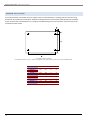
ANCHOR LOCATIONS
Four anchor locations are provided on the force plate so that it can be fastened to a mounting plate or to the floor using
standard ⅜"-16 (or M8-1.25) machine bolts. Standard mounting plates for each force plate model already have pre-drilled
anchor locations with steel-threaded inserts. The figure and table below gives the exact locations of the anchor points for
standard force plate models.
Force plate anchor locations
For numerical values of A, B, C, and D for different force plate models, please refer to the following table.
MODEL
4060-08
4060-10
4060-15
4550-08
4060-NC
4080-10
4080-15
6090-15
9090-15
6012-15
24
A
B
C
D
342
552
29
24
438
342
458
552
13
25
25
25
342
752
29
24
542
758
540
860
860
1113
29
71
30
24
20
44
Bertec Corporation Bertec Force Plates
AMPLIFIERS AND SIGNAL CONVERTERS
Signal conditioning and amplification for the force plates are provided by means of external amplifiers. Each force plate has an
internal digital preamplifier, which digitizes the analog signal from the transducer strain gauges, and conditions it through
oversampling, preliminary amplification, and filtering. The calibration matrix of the force plate is digitally stored on the
preamplifier so that the output is already calibrated data having the units of Newtons and Newton-meters. The output of the
force plate is a 16-bit digital signal using RS-485 format.
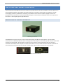
AM6500 DIGITAL SIGNAL CONVERTER
AM6500 Signal Converter
The AM6500 series external converter is used to collect data through the USB port of the computer. The input-output
connections for the AM6500 module are shown in the figure below. The output is a standard B-type USB connector. Next to the
connector are two LED lights. The lower light is on when the unit is powered, and the upper light comes on if the unit is
connected to the USB port of the computer. The input to the module is via a 9-pin D-Sub connector located at the back of the
unit located next to the power input. An external, universal power supply is used to provide power to the amplifier.
AM6500 Digital Signal Converter connections
25
Bertec Corporation Bertec Force Plates
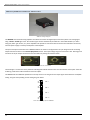
AM6501/AM6504 ANALOG AMPLIFIER
AM65xx analog amplifier
The AM65XX series external analog amplifiers are utilized to convert the digital output of the force plates to an analog signal
using a fixed or variable gain value. The number of gain values is indicated by the suffix XX in the model identifier (i.e. 6501 –
unity gain, 6504 – gain of four, etc.). These amplifiers also provide an auto zero button to remove tare load offset. An external,
universal power supply is used to provide power to the amplifier.
The input and output connections to the AM65XX modules are shown in the figure below. The pin assignments for the analog
output channels are shown in the General Specification section. The output voltage range for all channels is ±5V. Shorting pins 9
and 10 on the 15-pin output connector has the same effect as pushing the autozero button.
AM65XX series connections
The lower light is on when the unit is powered. A blinking LED indicates that the unit is not connected to a force plate. If the LED
is blinking, check all the cable connections to the force plate.
The AM6504 has two additional dipswitches on the top surface to set the gain for the output signal. Each switch has an ON/OFF
setting. The gains corresponding to each setting are given below:
ON
OFF
ON
OFF
ON
OFF
ON
OFF
1
2
1
2
GAIN = 1
GAIN = 2
1
1
2
GAIN = 5
2
GAIN = 10
Gain switch settings for the AM6504
26
Bertec Corporation Bertec Force Plates
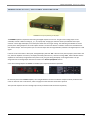
AM6800 DUAL OUTPUT, ADJUSTABLE GAIN AMPLIFIER
AM6800 Dual output adjustable gain amplifier
The AM6800 amplifier incorporates both analog and digital outputs into one unit. The gain of the analog output is user
selectable, and has 7 different settings (1, 2, 5, 10, 20, 50, 100). A single gain selection switch is provided for all 6 output
channels. A three-digit LED display on the front panel shows the current gain setting. The channel signal indicators show the
polarity of the analog output for the six force plate channels. The auto zero button is utilized to remove tare load offset from
each channel output. The mains power input is a universal input with the range 100-240 V, 50-60 Hz. The digital output is a USB
signal.
If the unit is not connected to a force plate, the digital display will read "PLA". After the force plate is properly connected to the
unit, when the amplifier is turned on, the display will briefly (about 0.5 sec.) show the message "CAL", which indicates that the
amplifier has successfully recognized the force plate. Finally, the gain setting will display on the digital readout. The pin
assignments for the analog output channels are shown in the General Specification section.
A 19" rack mounting adaptor for AM6800 is available upon request from Bertec Corporation.
AM6800 amplifier
On the front panel of the AM6800 amplifier, the two lights between the auto zero button and power switch, the bottom one
comes on when the unit is switched on, and the top light is lit after the auto zero button is pressed.
The input and output to the unit is through 9-pin and 15-pin female D-Sub connectors respectively.
27
Bertec Corporation Bertec Force Plates
GENERAL SPECIFICATIONS
The AM65XX series and AM6800 amplifiers provide a ±5 V full-scale calibrated analog output per rated load range for each of
the six force plate channels. For example, if the force plate has a ±10 kN load range for the Fz channel, then for a gain of unity,
the –5.00 V output corresponds to –10 kN, and +5.00 V stands for +10 kN (i.e. a sensitivity of 0.5 mV/N). The analog gain used in
data acquisition represents a trade-off between maximum load range and force plate sensitivity. If the same force plate above is
used with an amplifier gain of 5, then the load range will be limited to ±2 kN. This means the plate now has an increased
sensitivity of 2.5 mV/N. The analog load scale factors for specific force plates, given on the product data sheet supplied with the
force plate, are specified for a gain of one.
The analog output signals are filtered so that they have a standard bandwidth of 500 Hz. The actual analog gain ratios are
applied to the digital signal with an accuracy of 99.997%.
The auto zero button removes the signal offset and sets the analog output signal within ±5 mV. This feature can be used to
increase the useful measurement range of the force plate by shifting the signal baseline. Note that auto zero might not set the
mean value of the signal to true zero. Therefore, an additional offset removal through software is suggested.
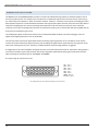
The digital input to all external amplifiers and signal converters is a female 9-pin D-Sub connector, whereas the analog output is
in the form of a female 15-pin D-Sub connector with the pin assignments shown below. Shorting pins 9 and 10 has the same
effect as pushing the autozero button on the AM6501 and AM6800.
The output range for each channel is ±5V.
8
7
15
6
14
5
13
4
12
3
11
2
10
1
9
CH1 : Pin 3
CH2 : Pin 4
CH3 : Pin 5
CH4 : Pin 6
CH5 : Pin 7
CH6 : Pin 8
GRND : Pin 10
Autozero: Pin 9
Pin configuration for the standard analog 15-pin connector
28
Bertec Corporation Bertec Force Plates
TROUBLESHOOTING
Problem: the data capture program is not capturing data
Solution: make sure that all cables are connected and that power is supplied. For USB devices, make sure that the current
drivers are installed. For analog devices, make sure that all software for them are set up correctly – you may need to contact the
analog vendor or Bertec Technical Support for further resolution.
Problem: the Bertec device reads incorrect data, such as too much weight on the plate
Solution: if using a hardware zero capable device, remove all weight from the device and press the auto zero button. For some
data capture applications, you will need to compute a zero baseline and normalize against that.
For any other issues, please contact Bertec Technical Support.
29
Bertec Corporation Bertec Force Plates
CUSTOMER SUPPORT
For any questions or inquiries regarding Bertec products you can contact:
Bertec Corporation
6171 Huntley Road, Suite J
Columbus, OH 43229, U.S.A.
Phone: +1 614 430-5421
Fax: +1 614 430-5425
E-mail: [email protected] or [email protected]
Web site: www.bertec.com
Suggestions or comments about Bertec products are always welcomed.
30
Bertec Corporation Bertec Force Plates
DOCUMENT REVISION HISTORY
Date
09/15/2009
03/27/2011
Revision
1.00
1.01
Initial Revision
Updated layout
Description
Author
Todd Wilson
Todd Wilson
31