1
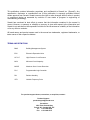
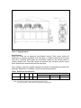
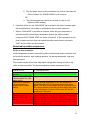
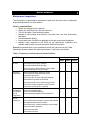
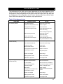
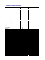
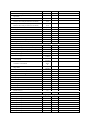
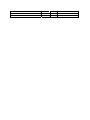
Chiller Manual
IOM-WC rev1
Oil-Free
Centrifugal Chiller
Installation, Operation &
Maintenance Manual
This publication contains information proprietary and confidential to Smardt Inc. (“Smardt”). Any
reproduction, disclosure or unauthorized use of this publication is expressly prohibited without
written approval from Smardt. Smardt reserves the right to make changes without notice in product
or component design as warranted by evolution in user needs or progress in engineering of
manufacturing technology.
Smardt has exercised its best efforts to ensure that the information contained in the manual is
correct. However, no warranty or reliability or accuracy is given with respect to the information and
Smardt is not and shall not be responsible or liable for the correctness or suitability of the information
or for any effort or omission.
All brand names and product names used in the manual are trademarks, registered trademarks, or
trade names of their respective holders.
TERMS AND DEFINITIONS
BMS
Building Management System
EXV
Electronic Expansion Valve
HP / LP
High Pressure / Low Pressure
MCA
Minimum Circuit Ampacity
MOCP
Maximum Over Current Protection
PLC
Programmable Logic Controller
RH
Relative Humidity
VFD
Variable Frequency Drive
For product support issues, corrections, or enquiries, contact :
Product Support
[email protected]
Smardt Inc.
1800 Trans Canada Hwy
Dorval, QC, Canada H9P 1H7
Tel : +1 514 426 8989
Fax: +1 514 426 5757
TABLE OF CONTENTS
Terms and Definitions ………………………………………………………………………
2
Installation and Safety Guidelines ………………………………………………..……….
4
Rigging ………………………………………………………………………………………..
7
Commissioning ……………………………………………………………………………….
11
Control Wiring Reference ……………………………………………………………………
12
Sequence of Operation ……………………………………………………………………..
13
Maintenance ………………………………………………………………………………….
17
Troubleshooting Guide ………………………………………………………………………
19
Service Procedures …………………………………………………………………………..
20
Removal and Installation of Compressors …………………………………………………
25
Heat Exchanger Service ……………………………………………………………………...
28
Incident Report Procedure ……………………………………………………………………
29
Downloadable Forms:
http://interactions.smardt.com/Docs/SmardtCommissioningForm.pdf
http://interactions.smardt.com/Docs/SmardtControlWiringConnections.pdf
http://interactions.smardt.com/Docs/Smardt_RequestStartUp_AcrobatForm.pdf
http://interactions.smardt.com/Docs/Smardt_IncidentReport_AcrobatForm.pdf
INSTALLATION and SAFETY GUIDELINES
General
The purpose of this manual is to inform contractors, building owners, and engineers of
installation, sequence of operation and service requirements for the Smardt oil-free
water-cooled centrifugal chiller. It is intended that this document be used with the
applicable installation and wiring drawings.
The water-cooled centrifugal chiller consists of an evaporator, condenser, twin-turbine
centrifugal compressor, compressor controller, and interconnecting refrigerant piping.
The chiller set is a packaged unit, requiring connection to the condenser and chilled
water circuits, as well as the main electrical supply and control wiring.
Safety Precautions
Safety precautions must be observed during installation, start-up, and service of the
chiller due to the presence of refrigerant charge and low voltage hazards.
Only qualified personnel should install, start up, and service this equipment.
Safety Guidelines
Ensure that relief valves vent outside the building in accordance with safety regulations.
Concentrations of refrigerant in enclosed spaces can displace oxygen and cause
asphyxiation.
Do not disable any safety devices.
This instruction manual contains the generally valid safety regulations that are of
the most importance to the operator of refrigeration units.
•
•
Always ensure that the Smardt chiller is operated by qualified staff only.
Provide suitable, fully operational fire extinguishing equipment.
Environmentally friendly handling
•
•
•
Observe the instructions on handling and storing refrigerant (see safety
data sheet).
Ensure that refrigerant does not escape into the air, the ground or the
sewage system.
Ensure that installation, set-up, maintenance and cleaning are only carried
out by certified companies that specialize in refrigeration units. Smardt
recommends having the service department install, set up, service and
clean the system.
Safe handling – staff
Staff involved with operation of the Smardt chiller should receive instruction with
regard to the following points at regular intervals a minimum of once a year.
• Risks involved in dealing with refrigeration units
• Safety stipulations
• Conduct in the event of accidents and malfunctions
• Measures in the event of accidents and malfunctions
Personal safety equipment
Operator’s obligations:
• To provide equipment to protect against the effects of refrigerants and
coolants.
• To store fully operational personal safety equipment outside of the at-risk
areas, within easy reach.
Personal safety equipment consists of:
•
•
Protective gloves made from leather
Protective goggles (for use with chemicals)
RISK of SUFFOCATION
R-134a is ASPHYXIATING
Common name of the substance: 1,1,1,2 tetrafluoroethane
Chemical name: CF3-CH2F
In the event that refrigerant escapes, please observe the following
• Have first aid equipment on hand
• Have emergency shower on hand
• Wear self-contained breathing apparatus – R134a is asphyxiating.
• Ensure that everyone leaves the danger area immediately.
• Follow first aid measures relevant to refrigerant
• Inform the local safety personnel.
• Only enter rooms where refrigerant has escaped if wearing the
appropriate safety equipment.
• Ventilate rooms in which refrigerant has escaped.
• Ventilate the hazardous area.
• Stop the gas escaping.
• Ensure that the refrigerant does not escape into the sewage system or
into the environment.
If the refrigerant concentration is more than 0.25 kg/m³:
• Wear self-contained breathing apparatus.
• Ensure that at least one person with the necessary safety equipment is
standing by to come to your aid. If the following are possible without
putting yourself at further risk:
• Switch off the Smardt chilling system using the emergency-stop button or
the master switch.
• Close the valves on the suction and liquid pipes.
5
• Observe instructions on the safety data sheet.
In case of contact with refrigerant observe the following
Cause
Symptoms
Measures
Gaseous refrigerant
has come into contact
with the eyes
Eye irritation
Rinse with plenty of clean water
immediately. Consult a doctor
immediately.
Liquid refrigerant has
come into contact with
the eyes
Extreme eye irritation, watery
eyes, redness and swollen
eyelids.
Rinse with plenty of clean water
immediately. Consult a doctor
immediately.
Gaseous refrigerant
has come into contact
with the skin
No risk
Liquid refrigerant has
come into contact with
the skin
Frostbite with burn-like skin
problems (redness, blistering)
Inhalation of gaseous
refrigerant
Inability to move,
unconsciousness Risk of
suffocation!
Rinse with plenty of clean water
immediately. Consult a doctor
immediately.
Take person out into the fresh
air immediately. Consult a
doctor immediately.
If patient stops breathing:
artificial resuscitation. Inform
the poison control center.
Storage and Handling
•
•
•
•
•
Only use refrigerant in ventilated areas.
Ensure that the container is sealed appropriately (cap, chain).
Only use containers which are suitable for Refrigerant R 134a and for the
intended pressure and temperature
Store containers at a temperature of less than 50 °C in a ventilated area.
Avoid long periods of exposure to heat.
Stability and Reactivity
Stability
Substances to be avoided
Other information
Stable under normal conditions
Refrigerant reacts strongly with alkali metals
and alkaline earth metals Pulverized aluminum
and pulverized zinc catalyzes the
decomposition of the refrigerant.
If escaping vapors come into contact with fire
or very hot objects, they form decomposition
products which produce a high degree of
irritation and have strong thermal effects. It is
possible that an explosive mixture could be
formed under high pressure and with a high
proportion of air.
WARNING!
Low voltage in electrical equipment is potentially lethal. Isolate incoming electrical power
before attempting installation or service of the equipment.
When AC power is first removed from the compressor, the capacitors store enough
energy to cause injury. It is essential to allow sufficient time for the capacitors to
discharge before proceeding. Only a qualified electrician should work on low-voltage
electronic equipment.
Wait at least 10 minutes after isolating power
before opening compressor access covers.
Foundation
Before installing the chiller set, ensure that the supporting floor meets the load bearing
requirements. Smardt is not responsible for the load bearing capacity of the floor.
Clearance
Adequate clearance around the chiller set is essential to facilitate maintenance and
service. Required minimum clearances are tabulated under Dimensions and clearances
on page 8.
Relief Valves
Ensure relief valves vent outside a building in accordance with national safety
regulations and Jurisdictional requirements. Concentrations of refrigerant in enclosed
spaces can displace oxygen and lead to asphyxiation.
Unpacking and inspection
When unpacking the unit, carefully inspect it for visible signs of damage. Check for
damaged evaporator insulation, broken wires, and loose piping and bolts. Any damage
should be reported to the shipping company immediately.
Open all containers and verify all parts against the packing list.
Report any shortages to Smardt.
RIGGING
Care must be exercised at all times when rigging or handling the chiller set to protect it
from damage. Four rigging points (two at each end) are provided on the evaporator tube
sheet corners. The chiller’s high center of gravity must be considered when rigging to
ensure that the chiller is secure and balanced when suspended. A spreader bar / I-beam
combination should be used to safely position the chiller set into its final location. The
typical rigging details are shown below in
Figure 1.
Smardt is not responsible for the rigging and placement of the unit. Arrangements can
be made through a local equipment mover.
7
Figure 1: Rigging Diagram
Unit Placement
Install the chiller set on approved anti-vibration mounts. Each corner should be
supported on vibration eliminators and steel plate or suitably isolated from the plant
room floor. Generally waffle pads are considered suitable as the Smardt chiller is
virtually vibration free. The chiller should be protected from excessive ground or pipe
borne vibration from external sources such as pumps.
Once installed, remove the rigging equipment and check for longitudinal and transverse
alignment. Add shims, if necessary, to level the unit along both axes.
Table 1 Dimensions and clearances
MODEL
SW840S-3A
H
81.4”
W
41.53”
L
165”
Lbs *
19000
Tube removal
150” from tubesheet
Clearances
Controls access
36” min side
*Includes full refrigerant charge – water circuits empty. Weights may vary with individual tube count.
NOTE: Values shown are typical. Refer to Smardt for product specific values.
Local codes may apply - ensure clearances comply with local codes/standards.
Service top side
12” min above
Figure 2: Dimensions and Clearances
The condenser and evaporator connections are grooved-type stubs (Victaulic®,
Shurjoint®, or other equivalent) for interconnection to the external water circuits. All
external piping must be adequately supported and aligned to prevent strain and
distortion on the chiller headers and couplings.
Pressure drops and flows
Table 2 Pressure drops and Flows
Evaporator
Condenser
NOTE:
Design flow
( GPM )
957
1153
Pressure drop
( PSI )
3.3
5.9
No. of
Passes
2
2
Conn. Size (nominal)
(inch )
8
8
Values shown are typical. Refer to Smardt for product specific values.
r circuits
The chiller set performance and efficiency can be adversely affected by contaminants in
the water circuits. Such contaminants may impede or block the flow of water through the
circuits or reduce heat exchanger performance.
Strainers should be located on the inlet side of the evaporator and condenser. Water
inlets to the chiller must be connected to the lower headers of the evaporator and
condenser. All external water piping must be cleaned or flushed before being connected
to the chiller set.
The water circuits should be arranged so that the pumps discharge through the
evaporator and condenser, and should be controlled as necessary to maintain
essentially constant chilled and condenser water flows through the unit at all load
conditions.
9
Figure 3 Piping Schematic
Control wiring
The primary chiller control functions are implemented either via a Carel® PLC, or the Kiltech
controller which looks after the control of chilled water temperature, interlocks, and interfacing
to the building system.
http://interactions.smardt.com/Docs/SmardtControlWiringConnections.pdf
Disconnects and power wiring
The mains power input connection for the Smardt range of chillers is a single point
termination via a mains termination box (supplied as standard) on each chiller unit. From
the mains termination box, each compressor control box (power and controls) is prewired to the individual compressors. All power wiring upstream of this point is the
responsibility of the installing contractor.
All wiring must be installed in accordance with appropriate local, and national electrical
codes and will require a circuit breaker or fuses to protect the main wiring run from the
final distribution sub-board to the unit. A neutral and an earth are essential.
Electrical data
Table 3 Pressure drops and Flows
NOTE:
MODEL
Voltage
MCA
MOCP
SW series
460 v 60 Hz 3 Phases
260
300
Values shown are maximum. Refer to Smardt for product specific values.
Compressor motors are designed to operate satisfactorily over a range of ± 10 percent
of the standard design voltage.
Note:
A Neutral is required for control purposes. The load is essentially a balanced 3 phase
load and the neutral may be run in the minimum allowable cable size relative to the three
phase mains.
COMMISSIONING
NOTE: Smardt requires equipment to be commissioned according to a detailed
procedure and by a Smardt and Turbocor trained and certified technician. In
order to activate the warranty, the commissioning form must be completed and
submitted to Smardt. An interactive Adobe Acrobat Form is available on-line at:
http://interactions.smardt.com/Docs/SmardtCommissioningForm.pdf
If Smardt is conducting the commissioning, or you request a factory supervised
start-up, please submit the Smardt request for Start-Up Form available on-line at:
http://interactions.smardt.com/Docs/Smardt_RequestStartUp_AcrobatForm.pdf
Before commissioning
•
•
•
•
•
•
•
•
•
•
•
•
•
•
•
Obtain the Smardt Commissioning Form and understand its requirements
Ensure that all the electrical connections and any pneumatic connections
have been set up in accordance with the plans and the local regulations.
Ensure that the PLC control system is available and is in working order.
Ensure that all communication links to higher-level control systems and
process control systems have been connected.
Ensure that the cold water/brine circuit has been filled and is operational.
Ensure that the refrigerating capacity is at 100%.
Ensure that test operation is possible at a minimum of half capacity over a
number of hours.
Ensure that the cooling water circuit has been filled, purged and is
operational.
Check that a heat load is available during start-up.
Check that insulation work has been completed.
Clean dust and rubbish from the unit.
Ensure that the unit is accessible from all directions.
Check refrigerant or protective gas filling at least once a month if
commissioning does not take place within 4 weeks after delivery. If this is
the case, instruct the relevant service office to do this.
Inform the relevant service office of any damages, prior to commissioning.
Agree on the commissioning date with the Smardt service office.
11
•
All materials needed for commissioning (refrigerant etc.) are to be
requested or made available.
Clearances
Adequate clearance around the chiller set is essential to facilitate maintenance and
service. Note and report if clearances are considered inadequate (re: Installation
Guidelines).
Damage inspection
Inspect it for visible signs of damage. Check for damaged evaporator insulation, broken
wires, and loose piping and bolts. Note any damage and report it to the appropriate
personnel on site.
Piping connections
All external piping must be adequately supported and aligned to prevent strain and
distortion on the chiller headers and couplings. Provision should be made to measure
pressure drop across each heat exchanger.
Evaporator and condenser water circuits
Strainers should be located on the inlet side of the evaporator and condenser. Water
inlets to the chiller must be connected to the lower headers of the evaporator and
condenser. The water circuits should be arranged so that the pumps discharge through
the evaporator and condenser, and controlled as necessary to maintain essentially
constant chilled and condenser water flows through the unit at all load conditions.
Control wiring reference data
The primary chiller control functions are implemented via a Carel ® PLC or the Kiltech
Controller which looks after the control of chilled water temperature, interlocks, and
interfacing to the building system. These connections are made at a 24 v terminal strip
inside the control cubicle. The Smardt Control Wiring Connections Form is on-line at:
http://interactions.smardt.com/Docs/SmardtControlWiringConnections.pdf
Chiller Controller I/O Functions for water cooled chillers (1~6 Compressors)
Temperature 1
Temperature 2
Temperature 3
Temperature 4
Temperature 5
Temperature 6
Temperature 7
Temperature 8
EnChW_temp
LvgChW_temp
EntCw_temp
LvgCw_temp
LiquidRefrig_temp
OutsideAirTemp
Not used
Not used
Entering chilled water temperature for control and monitoring
Leaving chilled water temperature for control and monitoring
Entering condenser water temperature for control and monitoring
Leaving condenser water temperature for control and monitoring
Liquid refrigerant temperature before the expansion valve.
Optional outside air temperature for data logging only
Digital Input 1
Digital Input 2
Digital Input 3
Digital Input 4
Digital Input 5
Digital Input 6
Digital Input 7
Digital Input 8
BMS Enable
ChW Flow Proof
Cw Flow proof
Not used
Ext LP Switch
Ext HP Switch
Gas Leak sensor
Ext FreezeStat
BMS Enable contact – starts and stops the chiller
Chilled water flow proof switch
Condenser water flow proof switch
External low pressure switch
External high pressure switch
Gas leakage sensor
External Freezestat input
Digital Output 1
Digital Output 2
Digital Output 3
Digital Output 4
Digital Output 5
Digital Output 6
Digital Output 7
Digital Output 8
Comp Interlock Relay
Tower VFD Enable
Chw Pump or vfd Relay
Cw pump or vfd Relay
Maximum capacity reached
Chiller Ready
Chiller Fault
Chiller Run
Compressor interlock relay output
Cooling tower VFD enable
Chilled water pump enable output
Condenser water pump enable output
Maximum capacity reached output, calls additional chillers
Closed when chiller is ready to run but not yet running
Closed when chiller is in fault state
Closed when chiller is running
Analog Input 1
Analog Input 2
Analog Input 3
Analog Input 4
Analog Input 5
Analog Input 6
Analog Input 7
Analog Input 8
Tower fan VFD Feedback
Chw Pump VFD Feedback
Cw Pump VFD Feedback
BAS Load Limit Input
Set Point Reset Input
Level Sensor or EXV Input
Combo RH/Temp Sensor T in
Combo RH/Temp Rh in
Tower or condenser fan VFD feedback (4-20mA)
Chilled water pump VFD feedback ( 4-20 mA)
Condenser water pump VFD feedback (4-20mA)
Building Automation System Amp Input feedback (4-20mA)
Set Point reset input , 0-5 VDC, 0-10 VDC or 4-20mA
Refrigerant level sensor input for EXV, 0-5 VDC, 0-10 VDC, 4-20mA
Outside air temp input for tower control 0-5VDC, 0-10VDC or 4-20mA
Outside RH input for tower control. 0-5 VDC, 0-10 VDC or 4-20mA
Analog Output 1
Analog Output 2
Analog Output 3
Analog Output 4
Analog Output 5
Analog Output 6
Tower Fan VFD or 3-Way Valve
Cw Pump VFD Output
ChW Pump VFD Output
Expansion Valve Output
Hot Gas Bypass Output
Power Output 0-600 kW
VFD cooling tower fan output. Controls Cw inlet temp. (4-20mA)
VFD condenser pump output (4-20mA)
VFD chilled water pump output (4-20mA)
Stepper motor output. Same loop for level control (4-20 mA)
Hot gas bypass capacity control output. 4-20mA or 0-10VDC
Chiller power output power
Power Wiring
All wiring must be installed in accordance with appropriate local, and national electrical
codes and will require a circuit breaker or fuses to protect the main wiring run from the
final distribution sub-board to the unit.
SEQUENCE OF OPERATION
General
The purpose of this section is to provide guide on the sequence of operation for the
Smardt oil-free centrifugal chiller. It is intended that this document be used with the
applicable installation
Starting with stopped chiller (chiller at idle)
1. Enable signal sent from BAS sets digital input on chiller control to true.
a. Chiller controller waits 5 seconds before acting on BAS enable.
2. If the leaving chilled water temperature is greater than or equal to the “set point
temperature” plus the “∆T over set point” and there are compressors available to
run the chiller is set to “PULL DOWN STATE”.
3. Depending on the number of compressors configured to start up initially and the
number of compressors available to run – compressors interlocks are closed and
15% demand is sent to each of the selected compressors.
13
4. Once the selected compressors are started up and begin to run the chiller
demand is increased at a fixed ramp rate of 5% per minute until a demand of
100% is reached or the temperature is less than or equal to the set point.
a. At any point during this demand ramp up (temperature pull down) if the
chiller demand goes over the “%Demand Stage Up” setting and a
compressor is available to run a new compressor will be turned on.
OR
b. At any point during this demand ramp up (temperature pull down) if the
chiller power goes over a calculated optimum number to switch on
another compressor and a compressor is available to run a new
compressor will be turned on.
Each time a new compressor is turned on the chiller controller is placed into a
“STAGE UP” state, initially in this state the demand to each of the operating
compressors is reduced in order to lower the ∆P across the evaporator and
condenser such that a new compressor easily without risk of surging – This may
last for roughly 120seconds. When a new compressor is started it is started at
the same demand as the other operating compressors, once this new
compressor has reached the same RPM as the other operating compressors the
“STAGE UP” sequence finishes and the fixed ramp to set point continues again.
5. Once the set point temperature is reached the chiller control mode is changed
from “PULL DOWN” to “RUN MODE”. When the chiller is placed in “RUN
MODE” the fuzzy pid loop takes over control of supplying demand to the
compressors based on the error between the set point and leaving chilled water
temperature.
a. If the chilled water temperature drops below the set point temperature for
a period greater than 5 continuous seconds the chiller controller starts to
look if it should shut down a compressor. The prerequisites for shutting
down a compressor are:
i. The compressor RPM must be reduced to within 5% of the
compressors lowest speed for the existing suction and discharge
pressure.
ii. The minimum time between compressor turn offs has expired
(generally set to 120seconds).
iii. The inlet guide vane must have remained at a position lower than the
chiller controller IGV STAGE DOWN% for 60 seconds
OR
iv. The chiller demand has reduced to less than or equal to 10%
(Minimum chiller loading).
6. If while the chiller is in the “RUN MODE” the heat load on the chiller increases again
the compressors are turned back on as detailed in the pull down sequence.
7. While in “RUN MODE” if the chiller is unloaded where only one compressor is
operational and the chilled water temperature drops to the chiller controller
configured “SHUT DOWN TEMP” the chiller is turned off. A 180 second anti-recycle
timer is started once this timer has expired the chiller control state is returned to
“IDLE” and the chiller may be re-started.
Abnormal operation sequences:
Chiller in alarm avoidance:
Chiller Management System continuously monitors for abnormal system conditions such
as low suction pressure, high discharge pressure, low leaving temperature, high amp
draw and others.
The controller implements a three stage alarm management strategy in order to stay
online as long as possible. The alarm management routine operates as follows:
ALARM STATE
All monitored values
Normal
One or more monitored
values is within 5% of the
alarm setting
One or more monitored
values is equal to or
greater than the alarm
setting
One or more monitored
values is equal to or
greater than the trip
setting
ACTION REQUIRED
No Action Required
If system is loading the system stops loading.
System demand is reduced by 0.5% per second until
demand reaches 10% or compressors ride to the surge
speed. If the alarm is still present and the compressors are
at the surge speed the controller will enter stage down state
turning compressors off every 120seconds until the last
compressor is left online.
Chiller is turned off, all compressors shutdown. The Fault
will be automatically reset after the time value setup in the
advanced setting screen (default = 180sec).
Once the fault has been reset the system is set back to idle
state where it must wait for 180sec anti-recycle timer before
starting the chiller again.
15
Discharge Pressure
Chiller detected fault:
If at any time whilst the chiller is running a fault condition is detected the chiller is placed
into fault state. The chiller will remain in the fault state for a pre-configured period of not
less than 180seconds after which time the fault will be automatically reset and the chiller
placed back to “IDLE” where the 180second anti-recycle timer is started again.
Compressor faults:
If a fault is generated inside the compressor:
•
If the fault is reset able such as a suction pressure, bearing displacement or
motor over temperature fault the chiller controller attempts to automatically reset
the fault and make the compressor useful again.
•
If the fault is not able to be reset such as a compressor over current trip or
system component failure the chiller controller places that compressor in a notuseable state and flags on touch screen that the compressor is “LOCKED OUT”.
A maximum of three compressor faults per hour are tolerated, if more than three faults in
an hour are generated the compressor is placed offline for a 20minute period (until fault
time expires).
If compressor does fault while the chiller is running and then reset that
compressor is then selected as the last compressor to startup when the load
increases.
MAINTENANCE
Maintenance inspections
The following list of preventative maintenance items must be carried out by authorized
and qualified personal in a timely fashion.
Owner's responsibilities:
• Report any damage to the chiller set.
• Report any faults that occur with the chiller set.
• Turn off the chiller if fault condition persists.
• Maintain a safe working environment in the plant room, free from obstructions
and debris.
• Provide adequate lighting.
• Ensure plant room ventilation is adequate and as per government regulations.
• Maintain water treatment to the chiller as per government regulations and
maintain water quality to prevent premature failure of the system.
Smardt recommends that on-site operational checks be carried out as per Table
Operational checks evaluate the system performance, fault history and trends.
Table 1. Frequency of maintenance for Smardt chillers:
ITEM
TASK
Frequency
3mths
Electrical
checks
6mths
12mths
Check Main power supply voltages
Check Electrical terminals are tight
Check Hot spots / discoloration on power cables
Check Amperages are as per design
Electronic
inspections
Compressor
refrigeration
circuit
inspections
Chilled water
circuit
inspection
Check communication cables are secure
Check pressure and temperature sensor
connections are secure.
Check there are no signs of physical damage /
discoloration on printed circuit boards.
Check the printed circuit boards are free of dust
Check EXV winding resistance (do NOT disturb
connections unless repair is required)
Check all mounting bolts are secure
Check for refrigerant leaks
Check for mechanical damage
Check operating temperatures and pressures
Check for Insulation damage.
Check chilled water sensors are secure and installed
with adequate heat transfer medium.
Check water flow / pressure drops are as per design.
Check flow switch operation.
Check for water leaks.
Check water strainers.
17
Condenser
water circuit
inspection
(if fitted)
Check condenser water sensors are secure and
installed with adequate heat transfer medium.
Check water flow / pressure drops are as per design.
Check flow switch operation.
Check for water leaks.
Check water strainers.
Air cooled
condenser
inspection (if
fitted)
Clean condenser tubes
Check cooling tower operation (refer manufacturers
specification(s))
Check airflow is not obstructed.
Check fin surfaces are clean
Check fans rotation (direction).
Check fan motor overload devices
Table 2. Frequency of Maintenance – Turbocor compressor
Item
Task
General
inspections
Electrical
inspections
Electronic
inspections
Refrigeration
Check for visible mechanical damage to
compressor
Check for excessive vibration from other
rotating equipment
Check main power supply voltages (refer to p
47 Turbocor service manual)
Check electrical terminals are tight
Check for signs of hotspots / discoloration on
power cables
Check amperages as per design
Check DC Bus voltage
Check capacitor mid bus voltage
Replace capacitor set
Check operation of all system safety devices
and interlocks
Check all communications cables are secure
and tight
Check all electronic modules are secure
Check physical condition of all exposed Printed
Circuit Boards (PCB’s)
Check all exposed PCB’s for dust build-up and
clean if necessary
Check calibration pressure / temperature
sensors
Check operation of IGV assembly
Check system refrigeration charge
Check superheat level / control, if applicable
Check system and motor cooling liquid line to
ensure sufficient subcooling
Check operating conditions external to the
compressor
Clean / inspect motor-cooling strainers (if
service has taken place)
Frequency
6 mths `12 mths 60 mths
As Required
TROUBLESHOOTING
The performance of the chiller set is largely dependent on the correct operation of the
water circuits and the refrigeration system. When evaluating the refrigeration system, it
is important to check the operation of the water circuits first. Failure to do this may lead
to misdiagnosis of the refrigeration circuit. Ensure that the chiller has sufficient water
flows in both the evaporator and condenser, as per specifications.
Table 2. Fault diagnosis chart
SYMPTOMS
Low suction pressure
POSSIBLE CAUSE
ACTION
Low chilled water flow
Check flow as per design
Chilled water temperature too low
Check set points
Faulty pressure transducer
Check transducer
Insufficient refrigerant charge
Check evaporator liquid level
Check sub-cooling
Check discharge temperature
Restricted refrigerant flow
Check EXV operation
Check filter driers
High discharge pressure (watercooled machines)
Suction valve closed
Compressor IGV stuck open
Check valve position
Check indicated position and
carry out standard IGV checks.
Condenser water temp. too high
Check tower set point
Low condenser water flow
Check flow as per design
Fouled water tubes
Blocked water strainer
Clean tubes
Clean strainer
Faulty pressure transducer Noncondensable in system.
Replace transducer
Dehydrate system
High discharge pressure (aircooled machines)
System overcharged
Adjust charge
Discharge valve closed
Check valve position
Restriction in pipe work
Correct pipe work
Blocked / restricted airflow
Remove obstructions
Air re-circulation
Remove cause of re-circulation
Fans reversed Electrical
overload(s) tripped
Correct power supply connection
Reset / investigate cause
Motor failure
Repair / replace
Replace transducer Dehydrate
system
Faulty pressure transducer Noncondensable in system
System overcharged
Adjust charge
Discharge valve closed
Check valve position
Restriction in pipe work
Correct pipe work
19
SYMPTOMS
High-evaporator pressure
POSSIBLE CAUSE
Chilled water temperature too
high
ACTION
Check temperature sensor.
Check for excessive water flow.
Pressure sensor faulty
Replace transducer
IGV failure
Check operation (refer procedure)
Low refrigerant temperature
cutout
Insufficient refrigerant charge.
Check refrigerant charge.
Faulty sensor. Water temperature
too low. Water flow blocked
Replace sensor.
Check set points.
Find / repair blockage
No motor cooling.
Check pipe work / valves.
Insufficient sub-cooling. Faulty
sensor
Check compressor solenoids
(refer service manual).
Drive temperature too high
Check refrigerant charge.
Check liquid line for restrictions.
Replace sensor
Compressor does not start
No cooling demand.
Check temperature set points.
Faulty chilled water temperature
sensors.
Replace faulty sensors.
Replace faulty sensors.
Faulty pressure sensors.
No mains power
Check power at mains terminal
block.
No chiller controller power
Check control circuit fuses / CB’s
SERVICE PROCEDURES
The following tools are required for servicing the chiller:
Service tools
Allen key set up to 14mm
Torx screwdriver #25
Manifold set
Thermometer
+1000VDC Multimeter
Computer with Turbocor Monitoring Software
Grounding wrist-strap
Connecting refrigerant gauges
It is extremely important that the manifold set is free of moisture and dust. It is also
important that the gauge set is not contaminated with other refrigerants or oil. When
performing any service procedure that requires the addition of refrigerant, do not use
reclaimed refrigerant unless it is of guaranteed quality and oil-free.
1.
Connect the low pressure hose (blue hose) to the access valve provided at
the suction ball valve.
2.
Connect the high pressure hose (red hose) to the access valve provided at
the discharge ball valve.
3.
Purge both gauge lines to ensure that non-condensables, which can lead to
false pressure readings, are removed from the line. Once this is complete,
the service technician can evaluate the refrigeration system.
Removing refrigerant
Whenever removing refrigerant from the evaporator and condenser vessels, water flow
must be established prior to carrying out this procedure. Water flow prevents a freeze-up
condition that will cause leaks between the water and refrigerant circuits, leading to
major component failure. This procedure may vary, depending on the type of service
required.
1.
Install the gauge manifold set or refrigerant recovery lines to the chiller set in
the appropriate area of service. Connect the common refrigerant hose to the
suction side of an approved refrigerant recovery system.
2.
Connect a hose between the discharge side of the recovery system and the
recovery container.
3.
Purge all lines of non-condensables.
4.
Switch on the recovery system and transfer the refrigerant. (The time of
transfer depends on the type of transfer system and the volume of
refrigerant.) To assist the transfer, it is important to maintain a cool recovery
cylinder. Once the system pressure is approximately 10 kPa, the system can
be opened up to atmosphere and the necessary repairs carried out.
Once the system is open for inspection, turn the water pumps off or isolate flow if the
system is in parallel with other chillers. If the water circuits are not shut down,
condensation will occur in the refrigeration pipe work, leading to longer than normal
evacuation times due to the presence of moisture in the system.
Refrigerant leak testing
Leak testing can be performed by the following means:
• Electronic leak detector
• Soapy water
21
Both of the above methods are adequate to locate leaks. Once the leak is isolated, the
system should be shut down and the affected component(s) repaired
Machine not operating - no charge
1.
Connect the service manifold set to the chiller as per procedure 4.2
2.
Connect gauge set-up to the R134A refrigerant cylinder and add a trace gas
(only required if electronic detection device is used).
3.
Connect the gauge set-up to an industrial grade nitrogen cylinder and
increase the pressure in the system to 1500 kpa.
4.
Carry out leak detection as per the above procedure.
Once the leak has been repaired, pressurize the system with nitrogen and leave
undisturbed for 24 hrs. Check the pressure gauge noting any change in pressure and
ambient temperatures from the previous day. (There may be slight pressure changes if
the ambient temperature has changed dramatically.) If the pressure in the system is
maintained, the nitrogen can be removed and the dehydration procedure (4.5) can be
performed on the chiller.
Dehydration procedure
When the system has been open for a lengthy period and contamination has occurred, it
is important to dehydrate the system to remove any moisture.
ATTENTION: Never apply power to the unit while under a vacuum.
NOTE:
Use the same hoses as in the leak testing procedure, making sure the lines are free of
leaks. If possible, use copper lines to minimize potential leaks between the chiller and
the vacuum pump.
1.
Install the evacuation hoses between the chiller and the vacuum pump.
2.
Start the vacuum pump.
3.
Open all isolation valves on the chiller to ensure that there is a vacuum
achieved throughout the system.
Once a vacuum has been achieved, connect an approved vacuum testing
device and check the results. If the vacuum reading is less than 500 microns,
isolate the vacuum hoses in the event that the reading is affected by the
running vacuum pump.
4.
5.
Let the chiller remain under vacuum for approx.1 hour. Recheck the vacuum
reading. If the reading does not increase by 50 microns within this time, the
chiller is ready to be recharged with refrigerant. If the system was severely
contaminated by an internal electrical failure or by the presence of moisture,
a triple dehydration procedure should be carried out, breaking the vacuum
each time with refrigerant or nitrogen to remove all contamination.
During operation, carry out refrigerant analysis on a regular basis and change filter driers
as required.
Charging the refrigeration system
Use pure refrigerant from non-contaminated cylinders.
1.
Turn on the chilled water and condenser water pumps.
2.
Connect up charging lines to the bottom of the evaporator vessel and the
charging cylinder.
3.
Purge lines, removing non-condensables.
4.
Add the correct amount of refrigerant charge to the evaporator vessel as
indicated by the name plate.
In the event that a minimum of 75% of the total refrigerant charge cannot be added to
the chiller, use an approved refrigerant pump to attain the minimum charge. The
machine will require restarting and the gas charge added during operation.
NOTE: The Turbocor compressors rely upon liquid refrigerant for the cooling of their
mechanical, electro-mechanical, and electronic components. Therefore in order to bring
the system to the correct operational refrigerant charge it may be necessary to connect
your charging lines onto the bypass port on the operational compressor, and provide
liquid to it during is operation. This will ensure adequate cooling for the compressor
whilst completing the charging of the system.
Refer to procedures 4.7 and 4.8 to determine the operational refrigerant charge, to
ensure system does not become over charged. During this procedure, it may be
necessary to bypass some control functions in order to maintain chiller operation and
thereby reach the desired refrigerant charge.
Check sub-cooling
Sub-cooling measurement procedure:
1.
Set up the service manifold as per procedure 4.2; however, connect the
discharge hose (red) to the liquid line upstream of the electronic expansion
valve (EXV).
2.
Note the corresponding saturation temperature of the refrigerant at the
pressure indicated. (In order to have sub-cooling, the measured value must
be less than the saturation temperature.)
3.
With a temperature probe, measure the temperature on the liquid line
upstream of the EXV.
4.
Calculate the difference between the saturated temperature and the
measured temperature. This difference is the amount of sub-cooling.
Design spec: 9-15° F (5-8° C).
23
Check superheat
Superheat Measurement Procedure:
1.
Connect up the service manifold as per procedure 4.2.
2.
Note the corresponding saturation temperature of the refrigerant at the
pressure indicated. (In order to have superheat, the measured value must be
greater than the saturation temperature.)
3.
With a temperature probe, measure the temperature on the suction line.
4.
Calculate the difference between the saturated temperature and the
measured temperature. This difference is the amount of superheat.
Design spec: 0-5° F (0-3° C).
Soldering procedure
When components in the refrigeration system require replacement, soldering or
sweating will be required to either remove or replace the components. To protect the
internal pipe work, the use of industrial grade nitrogen must be used at all times during
any procedure where a naked flame is applied to the pipe-work. The use of nitrogen
prevents copper oxide formation in the internal pipe work during the soldering process.
(This keeps the internal pipe work clean and free of contamination.)
1.
Connect the gauge manifold set as per procedure 4.2.
2.
Connect the common gauge line (yellow hose) to the nitrogen regulator.
3.
Set the regulator to provide a positive pressure of 5 psig.
4.
Open the nitrogen cylinder and manifold set to purge the area to be soldered.
(Nitrogen displaces any oxygen present in the pipe work.) During the
soldering process, be sure that any component that may be affected by the
addition of heat to the area be cooled by means of a wet rag wrapped around
the component.
5.
Once the soldering process is complete, cool down the pipe work and shut off
the nitrogen supply. Once cool, the system can be reassembled and tested
for leaks.
Checking IGV operation
During compressor ramp-up, the inlet guide
vanes open depending on load conditions,
as indicated by the ball bearing on the
outside of the IGV housing; refer to Figure
4. If the ball does not move, further testing
will be required; refer to the Compressor
Service Manual. When the Turbocor
compressor is not in operation the Inlet
Guide Vanes will move to the closed
position.
Checking Electronic Expansion Valve operation
During operation, the EXV modulates, maintaining the pre-set liquid level in the
evaporator. The EXV responds to the liquid level sensor via the chiller controller. Refer
to procedure 4.12 to verify the operation of the liquid level sensor. If the liquid level
sensor is operating correctly, use the chiller controller interface to manually drive the
EXV. Verify that the liquid level fluctuates according to the drive signal, as observed
through the sight glass on the cooler. If the EXV fails to respond to the manual input, the
EXV is defective and requires replacement.
Checking liquid level sensor operation
Be sure control type: Level is selected in the
controller. The level sensors have a display on
the back of the sensor. Observe the indicated
level to see that it varies (particularly during
startup). At stable conditions the level should
be maintained within 5 % of the set point
(normally 45 to 55 %). The sensor is a 0 to 90
ohm resistive element (45 ohms at indicated
50%).
REMOVAL AND INSTALLATION OF COMPRESSORS
DANGER
Before performing any service on the compressor, electrical power must be isolated. To
ensure safe and clear access to the compressor, follow these procedures:
1. Switch off the AC mains at the disconnect switch. Install a lock-out device or
place a placard at the switch alerting others that compressor servicing is in
progress. Wait at least 10 minutes before opening any of the compressor
access covers.
When AC power is first removed from the compressor, the DC link capacitors
store enough energy to cause electrocution. Allow sufficient time for the capacitors to
discharge before proceeding.
2. Using a #25 bit, remove the four Torx screws that secure the mains input cover
to the main compressor housing. Refer to Figure 5.
3. NOTE: Ensure the removal of all four Torx screws, paying special attention to the
removal of the screw in the top left of the mains input cover, as failure to remove
may result in damage to the cover
25
4. Lift away the mains input cover and set aside.
5. With a voltmeter, verify that there is no voltage present on all three phases.
6. Using a #25 bit, remove the Torx screws that secure the top cover to the main
compressor housing.
7. Lift away the top cover and set aside.
8. With a voltmeter, verify that there is no voltage present on the DC bus.
9. Remove the screws that secure the service-side cover.
10. Lift away the service-side cover and set aside.
Refrigerant Containment
Isolation and recovery of the refrigerant must be performed by a qualified service
technician.
1. Close the suction butterfly valve.
2. Close the discharge ball valve.
3. Close the inter-stage ball valve (if fitted).
4. Close the motor cooling shut-off valve.
5. Connect the service gauge as per procedure 4.2.
6. Connect an approved refrigerant recovery system to the compressor as per procedure
4.3 and transfer the refrigerant into a clean cylinder.
Compressor Removal
Refer to 5.1 "Preparation for Service" steps 1 through 7 prior to commencing the
removal procedures.
1. Remove the terminal nuts from the terminal block using a 16mm socket and wrench.
2. Remove the AC mains cables from the terminals.
3. Loosen the gland nut on the mains input bracket and pull the power cable through the
opening until it is completely detached from the compressor.
4. Disconnect the communication/interlock cables from the compressor I/O connector
module. Make sure that there is no secondary power source connected to the terminal
block before disconnecting any sensors or relay inputs/outputs. Once the transfer of
refrigerant is complete, disconnect the service isolation valves.
5. Using a 24mm wrench, remove the suction ball valve bolts.
6. Using a 8mm hex key, remove the discharge ball valve bolts.
7. Using a 8 mm hex key, remove the inter-stage ball valve bolts.
8. Remove the motor cooling connection at the rear of the compressor.
9. Replace the top cover and secure it using Torx screws.
10. Replace the main input cover and secure it using Torx screws.
11. Remove the four compressor mounting bolts using a 9/16” socket.
12. Connect an approved lifting device, such as a mobile hydraulic lifter, to the eyebolts
provided on each side of the compressor.
13. Remove the compressor.
14. Using the blanking plates provided with the new compressor, seal up the compressor
in preparation for shipment to the supplier; this will prevent moisture and foreign material
from entering the compressor, possibly affecting the compressor strip-down and analysis
procedures.
Compressor installation
Install new o-rings only when reattaching the ball valves to the compressor.
1. Remove the blanking plates provided with the new compressor.
2. Connect an approved lifting device, such as a mobile hydraulic lifter, to the eyebolts
provided on each end of the compressor.
3. Position and align the compressor over the mounting base.
4. Insert the four compressor mounting bolts that secure the compressor to the chiller.
Tighten the screws using a 16mm socket.
5. Attach the motor cooling connection at the front of the compressor.
6. Using a 8 mm hex key, tighten the inter-stage valve bolts.
27
7. Using a 8mm hex key, tighten the discharge service valve bolts.
8. Using a 14mm hex key, tighten the suction service valve bolts.
9. Connect the communication/interlock cables to the compressor I/O connector module.
10. Using a #25 bit, remove the four Torx screws that secure the main input cover. Lift
away cover. Make sure that electrical power is isolated from the AC mains cables before
handling
them.
11. Route the power cable through the opening in the mains input bracket.
12. Attach the AC mains cables to the terminals, and the grounding cable to the
grounding lug.
13. Attach the terminal nuts to the terminal block using a 16mm socket and wrench.
14. Tighten the gland nut on the mains input bracket.
15. Replace the main input cover and secure it using Torx screws.
NOTE: Suction and discharge valves are meant to be used for service only. Do not run
the unit or leave open for extended periods of time. If it is intended it will be open for
extended periods use planking plates with gaskets and test of leaks.
HEAT EXCHANGER SERVICE
Air-Cooled Condenser
The Smardt condenser is a vertical air flow cross finned coil heat exchanger design. The
coil is horizontal and incorporates a separate sub cooling circuit and may have a liquid
receiver located between the main and sub cooling circuits to ensure that the main
circuit does not liquid lock.
No regular service is required; however the following checks should be made on a
regular basis:
• Ensure that the motors protection devices (in the main cubicle) are not tripped.
• Check the general state of the fin surfaces for built up soiling. A build up of dust
adhering to the fins in greasy environments can lead to air flow reduction and
poor heat exchange. Generally steam or pressure spray cleaning in the most
appropriate cleaning method.
Evaporator – shell-and-tube type
Shell-and-tube type evaporators should be treated as described for condensers above.
Evaporator – shell-and-plate type
An alternative Smardt flooded shell-and-plate evaporator may be fitted. This type is not
mechanically cleanable. Chemical cleaning methods may be used but it is essential to
ensure that the chemicals used are compatible with and will result in no harm to the
materials of construction.
Materials are:
Copper (coating – heat exchange plates)
Stainless steel (heat exchange plates)
Low carbon steel (water connections)
Proceed generally as follows:
1. Shut down the chiller set and isolate from the power.
2. Isolate and drain down the cooler water circuit, including the pump and inlet filter.
3. Remove the inlet filter and inspect it for the possible cause of the problem.
4. Replace the filter.
5. Follow the chemical suppliers procedure to introduce the chemicals only to the cooler.
6. Flush thoroughly afterwards, then seal the water circuit and refill the system. Bleed
the water circuit.
7. Re-connect power and monitor the chiller operation at startup.
INCIDENT REPORT PROCEDURE
Smardt strives for product excellence and maintains a competent staff of professionals in
application design and service to serve our customers. If you have a problem with a
Smardt chiller, we want to know about it. To report an incident and request an RMA,
please submit a Chiller Incident Report. This form is available on-line at:
http://interactions.smardt.com/Docs/Smardt_IncidentReport_AcrobatForm.pdf
29
110 VAC
DI-3
DI-4
DI-5
DI-6
DI-7
DI-8
RLY-1
RLY-2
RLY-3
RLY-4
RLY-5
RLY-6
RLY-7
RLY-8
COM
COM
COM
COM
COM
RLY-1
RLY-2
RLY-3
RLY-4
RLY-5
RLY-6
RLY-7
RLY-8
Gnd
N
N
N
110
110
110
FUSE – 2A
AO-6
AO-6
AO-5
AO-5
AO-4
AO-4
AO-3
AO-3
AO-2
AO-2
AO-1
AO-1
AI-8
AI-8
AI-7
AI-7
AI-6
AI-6
AI-5
AI-5
AI-4
AI-4
AI-3
AI-3
AI-2
AI-2
AI-1
AI-1
DI-2
T7
TC
COM
T6
TC
COM
T5
TC
T8
T4
TC
DI-1
T3
TC
COM
T2
TC
TC
T1
TC
24N
24N
24N
24V
24V
24V
_
+
_
+
_
+
_
+
_
+
_
+
_
+
_
+
_
+
_
+
_
+
_
+
_
+
_
+
Touch Screen Power
Supply
AO-6, Electrical Power Output 0 to 600kW (4-20mA)
AO-5, HotGas Valve Output (4-20mA)
AO-4, Refrigerant Level Control Output (4-20mA)
AO-3, Chilled Water Pump VFD Speed Signal (4-20mA)
AO-2, Condenser Pump VFD Speed Signal (4-20mA)
AO-1, Tower/ Condenser Fan VFD Speed Signal (4-20mA)
AI-8, Remote outside air RH% (4-20mA, 0-5VDC, 0-10VDC)
AI-7, Remote outside air temperature (4-20mA, 0-5VDC, 0-10VDC)
AI-6, Refrigerant Level Sensor (4-20mA, 0-5VDC, 0-10VDC)
AI-5, BAS Set point reset (4-20mA, 0-5VDC, 0-10VDC)
AI-4, BAS Load Limiter 0-100% (4-20mA)
AI-3, Cw Pump VFD Feedback (4-20mA)
AI–2, Chw Pump VFD Feedback (4-20mA)
AI–1, Tower / Condenser Fan VFD Feedback (4-20mA)
RLY-1 Compressor Interlock Relay
RLY-2 Tower Fan or Evap Condenser VFD Enable Signal
RLY-3 Chilled Water Pump Enable or Pump VFD Enable
RLY-4 Condenser Water Pump Enable or Pump VFD Enable
RLY-5 Maxim Capacity Reached ~ Call for help
RLY-6 Chiller Ready relay
RLY-7 Chiller Faulted relay
RLY-8 Chiller Running relay
Power to Touch
Panel
DI-1, BAS Enable Input – Normally Open, Close to enable chiller
DI-2, Chw Flow Input – Chiller Faults if opens while running
DI-3, Cw Flow Input – Chiller Faults if opens while running
DI-4, Not Used
DI-5, HP Safety Switch – External manual reset high pressure switch
DI-6, LP Safety Switch – External low pressure switch
DI-7, Gas Leakage Input
DI-8, Ext Freeze Stat
T-1, Entering Chilled Water Temp
T-2, Leaving Chilled Water Temp
T-3, Entering Cond Water Temp
T-4, Leaving Cond Water Temp
T-5, Liquid Refrigerant Temp (Single Ckt Chillers Only)
Compr Interlock #8
Compr Interlock #7
Compr Interlock #6
Compr Interlock #5
Compr Interlock #4
Compr Interlock #3
Compr Interlock #2
Compr Interlock #1
24vac relays
Used to close
compr interlocks
Level
RS485 COMMS TO TOUCH
PANEL
RS485
RUN
I-LOCK
LVG T
Compressor I/O PCB’s –
Same fro each module
+ c + -
FUSE – 6A
s
+ -
24VAC
(Not Grounded)
Electronic
Expansion
Valve
Liquid Level
Sensor
M
Leaving Water Temp Of
Module
Modular Single Compressor
Chillers Only!
Wiring Diagram
Wiring diagram
Controller Default and Custom Settings
SETTING DESCRIPTION
Default
Setting
COMMENT
Temperature Regulation Settings
Chilled air/water set point
45˚F
Leaving or entering air/water control
Leaving
Dead Band
0.1˚F
Proportional band
18
Integral Gain
2500
Derivative Gain
5000
Control Min
5%
Max Slew Rate
5%
∆T Above Set point to Start
4˚F
Stop Chiller Temp (Safe shut down~ Set above alarm)
42˚F
Condenser Control Settings
Minimum Set point temperature
Maximum Set point temperature
Starting%
Starting Timer
Starting Set point
Set point change per minute
Proportional Band
Integral Gain
Control Min
Max Slew Rate
Suction pressure alarm
Suction pressure trip
Suction trip timer
Discharge pressure alarm
Discharge pressure trip
Discharge trip timer
System amp alarm (Chiller specific)
System amp trip (Chiller specific)
Over amp trip timer
Leaving temperature alarm
Leaving temperature trip
Leaving high temp limit while running
Leaving high temp time limit
Condenser water high temp alarm
Condenser water high temp trip
Auto fault reset delay timer
%Demand Stage Up
% RPM Stage Up
% RPM Stage Down
Power Stage Up %
Stage up time delay
Stage down time delay
65˚F
85˚F
25%
120sec
75˚F
0.5˚F
20˚F
2500
0%
5%
Alarm Settings
30 psig
26 psig
15 sec
150 psig
160 psig
15 sec
Xxx
Xxx
45 sec
38˚F
36˚F
55˚F
30 min
95˚F
100˚F
180 sec
Compressor Staging Settings
90%
60%
5%
100%
240 sec
120 sec
31
Pressure ratio limit
IGV% before stage down
Number of compressor to start (Chiller/ Site
dependent)
Look forward time
Temperature Reset (upper) (only works if reset
based on return temp is selected as reset mode)
Temperature Reset (lower) (only works if reset
based on return temp is selected as reset mode)
Display Units
Comp Mode
Pass Code
Chiller Address
RS485Baud (Chiller to BAS comms)
Evaporator VFD Tuning
Condenser VFD Tuning
Design kW input (Chiller dependent)
Number of compressors (chiller dependent)
Number of refrigerant circuits (chiller dependent)
Three phase VAC (Site dependent)
Compressor Type
Evaporator Type
Condenser Type
Control Mode
Condenser Control Mode
Stage Mode
Chiller model (chiller dependent)
Temperature reset mode
Hot Gas Valve Settings
Proportional Band
Integral gain
Control Min
Max Slew Rate
Starting %
Starting Timer
Set point (∆T Below the set point)
Manual Valve %
Step Count
Temperature Input#1 Offset
Temperature Input#2 Offset
Temperature Input#3 Offset
Temperature Input#4 Offset
Temperature Input#5 Offset
Temperature Input#6 Offset
Temperature Input#7 Offset
Temperature Input#8 Offset
2.2
75%
Xxx
1 sec
0˚R /
54˚F
4˚R /
45˚F
Imperial
Modbus
0
1
19200
35
45
Xxx
System Setup
Xxx
Xxx
Xxx
TT300
Flooded
Water
Cooled
PID
Leaving
Cond
Water
In
Equal
run time
Xxx
AI #5
2˚F
1500
0%
5%
50%
180 sec
1˚F
0%
24000
Sensor & Analogue Input Settings
0˚R
0˚R
0˚R
0˚R
0˚R
0˚R
0˚R
0˚R
Analogue Input Scaling
AI-1 Cond Fan VFD Speed Feed Back
0/0/100
AI – 2 Chilled Water Pump VFD Speed Feed Back
0/0/100
AI – 3 Condenser Water Pump VFD Speed Feed Back
0/0/100
AI – 4 BAS Load Limit input
0/50/100
AI – 5 Set point Reset
0/0/10
AI – 6 Refrigerant Level Sensor
0/0/100
AI – 7 Remote Temp Sensor
0/32/150
AI- 8 Remote RH% Sensor
0/0/95
Electronic Expansion Valve Settings
Proportional Band
Integral gain
Control Minimum (min valve position per compressor)
Max Slew Rate
Starting %
Starting Timer
Min SH Set point
Max SH Set point
Minimum Sub-cooling
Manual Valve %
Step Count
5˚R
500
7%
5%
25%
120sec
-2˚R
1˚R
2.5˚R
0%
24000
Record of compressor controller settings
SETTING DESCRIPTION
Default
Setting
COMMENT
Compressor Alarm and Trip Settings
Compressor Control Mode
Display Units
Discharge pressure alarm limit
Discharge temperature alarm limit
Suction pressure alarm limit
Leaving temperature alarm limit
Current alarm limit (Chiller dependant)
Discharge pressure trip limit
Discharge temperature trip limit
Suction pressure trip limit
Leaving temperature trip limit
Current trip limit (Chiller dependant)
Modbus
Imperial
155
90
28psig
38˚F
Xxx
170
95
25psig
36˚F
Xxx
Electronic Expansion Valve Settings (Modular Chillers Only)
Control Mode
Auto/Manual
Stepper Startup%
Stepper Startup position delay
Stepper control set point
Stepper control loop speed
Stepper minimum count
Maximum step count
Liquid
Level 1
Auto
25%
120 sec
35%
45%
10%
6000
RS485 Modbus Settings
33
Slave Address (Compressor dependent 1~6)
Baud Rate
Stop bits
Xxx
38400
2