1
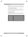
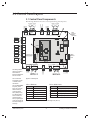
PRINTER’S INSTRUCTIONS:
MANUAL,INSTALLATION,E3 EMERGE,UL - P/N: 620-100531 B - INK: BLACK - MATERIAL: GUTS 80G WOOD FREE, COVER 157G COATED GLOSS ART
SIZE: FLAT 17.000” X 11.000”, FOLDED 8.500” X 11.000” - FOLDING: ALBUM FOLD - BINDING: SADDLE STITCH - SCALE: 1-1
e3 eMerge
Access Control System
Document Number: 620-100531, Rev. B
Installation Instructions
Notices
All rights strictly reserved. No part of this document may be reproduced, copied, adapted, or
transmitted in any form or by any means without written permission from Nortek Security &
Control LLC.
Standards Approvals
This equipment has been tested and found to comply with the limits for a Class A digital device,
pursuant to part 15 of the FCC Rules. These limits are designed to provide reasonable protection
against harmful interference when the equipment is operated in a commercial environment.
This equipment generates, uses, and can radiate radio frequency energy and, if not installed
and used in accordance with the instruction manual, may cause harmful interference to radio
communications. Operation of this equipment a residential area is likely to cause harmful
interference in which case the user will be required to correct the interference at his own expense.
e3 eMerge systems are Level I UL 294 listed devices and must be installed in controlled locations.
Corporate Office
Nortek Security & Control LLC
1950 Camino Vida Roble, Suite 150
Carlsbad, CA 92008-6517
Tel: (800) 421-1587 / 760-438-7000
Fax: (800) 468-1340 / 760-931-1340
Technical Support
Tel: (800) 421-1587
Hours: 5:00 AM to 4:30 PM Pacific Time, Monday - Friday
Notice
It is important that this instruction manual be read and understood completely before installation
or operation is attempted. It is intended that the installation of this unit will be performed only
by persons trained and qualified in the installation of access control equipment. The important
safeguards and instructions in this manual cannot cover all possible conditions and situations
which may occur during installation and use. It must be understood that common sense and
caution must be exercised by the person(s) installing, maintaining and operating the equipment.
This installation manual is for e3 eMerge systems.
Contents
1.0 Introduction
. . . . . . . . . . . . . . . . . . . . . . . . . . . . . . . . . . . . . . . . . . . . . . . . . . . . . . . . . . . . . . . . . . . . . . . . . . . . . .2
1.1 Access Control Overview. . . . . . . . . . . . . . . . . . . . . . . . . . . . . . . . . . . . . . . . . . . . . . . . . . . . . . . . . . . . . . . . . . . 2
1.2 System Overview . . . . . . . . . . . . . . . . . . . . . . . . . . . . . . . . . . . . . . . . . . . . . . . . . . . . . . . . . . . . . . . . . . . . . . . . . . 2
1.3 Installation Overview Checklist. . . . . . . . . . . . . . . . . . . . . . . . . . . . . . . . . . . . . . . . . . . . . . . . . . . . . . . . . . . . . 3
2.0 Control Panel Layout . . . . . . . . . . . . . . . . . . . . . . . . . . . . . . . . . . . . . . . . . . . . . . . . . . . . . . . . . . . . . . . . . . . . 4
2.1 Control Panel Components . . . . . . . . . . . . . . . . . . . . . . . . . . . . . . . . . . . . . . . . . . . . . . . . . . . . . . . . . . . . . . . . 4
3.0 Installing the Control Panel . . . . . . . . . . . . . . . . . . . . . . . . . . . . . . . . . . . . . . . . . . . . . . . . . . . . . . . . . . . 5
3.1 Mounting the Compact Enclosure . . . . . . . . . . . . . . . . . . . . . . . . . . . . . . . . . . . . . . . . . . . . . . . . . . . . . . . . . . 5
3.2 Mounting the Metal Enclosure . . . . . . . . . . . . . . . . . . . . . . . . . . . . . . . . . . . . . . . . . . . . . . . . . . . . . . . . . . . . . 7
4.0 System Power . . . . . . . . . . . . . . . . . . . . . . . . . . . . . . . . . . . . . . . . . . . . . . . . . . . . . . . . . . . . . . . . . . . . . . . . . . . . . 8
4.1 Power Connection for Systems using Compact Enclosure . . . . . . . . . . . . . . . . . . . . . . . . . . . . . . . . . . . 8
4.2 Power Connection for Systems using Metal Enclosure. . . . . . . . . . . . . . . . . . . . . . . . . . . . . . . . . . . . . . 10
4.3 PoE Connection (optional) . . . . . . . . . . . . . . . . . . . . . . . . . . . . . . . . . . . . . . . . . . . . . . . . . . . . . . . . . . . . . . . . 11
5.0 Inputs and Outputs . . . . . . . . . . . . . . . . . . . . . . . . . . . . . . . . . . . . . . . . . . . . . . . . . . . . . . . . . . . . . . . . . . . 12
5.1 System Inputs . . . . . . . . . . . . . . . . . . . . . . . . . . . . . . . . . . . . . . . . . . . . . . . . . . . . . . . . . . . . . . . . . . . . . . . . . . . . 12
5.2 Wiring the Inputs . . . . . . . . . . . . . . . . . . . . . . . . . . . . . . . . . . . . . . . . . . . . . . . . . . . . . . . . . . . . . . . . . . . . . . . . 13
5.3 System Outputs . . . . . . . . . . . . . . . . . . . . . . . . . . . . . . . . . . . . . . . . . . . . . . . . . . . . . . . . . . . . . . . . . . . . . . . . . . 14
5.4 Door Lock Outputs . . . . . . . . . . . . . . . . . . . . . . . . . . . . . . . . . . . . . . . . . . . . . . . . . . . . . . . . . . . . . . . . . . . . . . . 15
6.0 Readers. . . . . . . . . . . . . . . . . . . . . . . . . . . . . . . . . . . . . . . . . . . . . . . . . . . . . . . . . . . . . . . . . . . . . . . . . . . . . . . . . . . 16
6.1 Wiring the Readers . . . . . . . . . . . . . . . . . . . . . . . . . . . . . . . . . . . . . . . . . . . . . . . . . . . . . . . . . . . . . . . . . . . . . . . 16
7.0 Network Connection . . . . . . . . . . . . . . . . . . . . . . . . . . . . . . . . . . . . . . . . . . . . . . . . . . . . . . . . . . . . . . . . . . 17
7.1 Preparing for the Network . . . . . . . . . . . . . . . . . . . . . . . . . . . . . . . . . . . . . . . . . . . . . . . . . . . . . . . . . . . . . . . . 17
7.2 Connecting to the Network . . . . . . . . . . . . . . . . . . . . . . . . . . . . . . . . . . . . . . . . . . . . . . . . . . . . . . . . . . . . . . 18
7.3 Adding a Client. . . . . . . . . . . . . . . . . . . . . . . . . . . . . . . . . . . . . . . . . . . . . . . . . . . . . . . . . . . . . . . . . . . . . . . . . . . 20
7.4 Configuring the Client and Server on the Network . . . . . . . . . . . . . . . . . . . . . . . . . . . . . . . . . . . . . . . . . 21
7.5 Programming the System . . . . . . . . . . . . . . . . . . . . . . . . . . . . . . . . . . . . . . . . . . . . . . . . . . . . . . . . . . . . . . . . . 24
8.0 Troubleshooting . . . . . . . . . . . . . . . . . . . . . . . . . . . . . . . . . . . . . . . . . . . . . . . . . . . . . . . . . . . . . . . . . . . . . . . 25
9.0 Test, Maintenance and Service . . . . . . . . . . . . . . . . . . . . . . . . . . . . . . . . . . . . . . . . . . . . . . . . . . . . . 26
9.1 Testing . . . . . . . . . . . . . . . . . . . . . . . . . . . . . . . . . . . . . . . . . . . . . . . . . . . . . . . . . . . . . . . . . . . . . . . . . . . . . . . . . . . 26
9.2 Maintenance . . . . . . . . . . . . . . . . . . . . . . . . . . . . . . . . . . . . . . . . . . . . . . . . . . . . . . . . . . . . . . . . . . . . . . . . . . . . . 26
9.3 Service . . . . . . . . . . . . . . . . . . . . . . . . . . . . . . . . . . . . . . . . . . . . . . . . . . . . . . . . . . . . . . . . . . . . . . . . . . . . . . . . . . . 26
9.4 Parts List . . . . . . . . . . . . . . . . . . . . . . . . . . . . . . . . . . . . . . . . . . . . . . . . . . . . . . . . . . . . . . . . . . . . . . . . . . . . . . . . . 26
10. Notes . . . . . . . . . . . . . . . . . . . . . . . . . . . . . . . . . . . . . . . . . . . . . . . . . . . . . . . . . . . . . . . . . . . . . . . . . . . . . . . . . . . . . 28
www.linearcorp.com
1
e3 eMerge Installation Instructions
1.0 Introduction
This manual contains information regarding the basic installation, wiring and configuration of the
e3 eMerge browser-based access control systems. Systems are available in a space-efficient and
durable plastic housing or in a heavy-duty steel cabinet featuring a self-contained battery back-up
with a supervised power supply. All systems use the same control panel layout and system wiring.
1.1 Access Control Overview
Access control systems are designed to monitor and control access throughout a building or
restricted area. An access control system involves the use of an access device (card, PIN code,
etc.), which is presented at an entry device (reader/keypad) to gain access. When access is granted,
a door is unlocked for a pre-programmed amount of time and a transaction is recorded in a
database for reporting or tracking purposes.
1.2 System Overview
Systems are available in a variety of models starting with one door, two reader configurations.
Models can be upgraded with expanded capabilities using optional software license keys. The
e3 eMerge includes Ethernet support, an integrated web server and Power over Ethernet (PoE)
support.
Specifications
Processor
On-board RAM
Power
Operating system
Transactions per second
Plastic enclosure (W x H x D):
Steel enclosure (W x H x D)
Temperature specification
www.linearcorp.com
Cortex 1GHz
512MB DDR2 (333MHz)
Regulated 12VDC @ 2A
Embedded Linux
> 30
12.25 in x 11.1 in x 2.23 in
17.75 in x 14.25 in x 6.5 in
-4°F to 120°F (-20°C to 50°C)
2
e3 eMerge Installation Instructions
1.3 Installation Overview Checklist
Note: The checklist
provides a logical
sequence for installing a
system.
The following list presents the steps required for successfully installing a system.
❒ Mount the enclosure
❒ Connect the readers
❒ Wire the inputs and outputs
❒ Connect power to the system
❒ Obtain IP address and other TCP/IP information from network administrator
❒ Configure the network settings for the system
❒ Connect the system to a local area network (LAN)
❒ (Optional) Add licenses for additional doors and readers
www.linearcorp.com
3
e3 eMerge Installation Instructions
2.0 Control Panel Layout
2.1 Control Panel Components
The following illustration shows the e3 control panel wiring and components.
-
DOOR 4
D0 IN
D1 IN
D0 OUT
D1 OUT
12V
2
INPUT
GND
INPUT
AUX IN
GND
AUX IN
D0 IN
D1 IN
D0 OUT
D1 OUT
INPUT
GND
INPUT
+
REX
GND
DOOR
CONTACT
REX
GND
DOOR
CONTACT
-
IN READER OUT READER
AUX INPUT 4
GND
AUX INPUT 3
OUT READER IN READER
+
12V
4
DOOR 3
D9
EARTH
GROUND &
READER
SHIELD LEAD
NC
DOOR 3 LOCK
C
NO
DOOR 4 LOCK
LAN LED
DL19
DL18
NC
C
ETHERNET
NO
1
NC
AUX RELAY 4
C
LED BANK
NO
NC
AUX RELAY 3
DL17
DL16
DL15
DL14
DL13
DL12
DL11
DL10
DL9
C
NO
NC
AUX RELAY 2
C
NO
RESET
NC
AUX RELAY 1
C
NO
DOOR 2 LOCK
DL8
DL7
DL6
DL5
DL4
DL3
DL2
DL1
TMP TMP +
FLT FLT +
S2
S2: Hardware reset
S1: Factory default
NC
-
S1
C
+
TAMPER
PWR FAULT
+ 12VDC
NO
Micro SD
SLOT
NC
JP1
C
NO
3
DOOR 2
-
INPUT
GND
INPUT
D0 IN
D1 IN
D0 OUT
D1 OUT
INPUT
GND
INPUT
+
AUX IN
GND
AUX IN
DOOR 1
12V
12V
+
D0 IN
D1 IN
D0 OUT
D1 OUT
DOOR 1 LOCK
-
Note: The terminals
are designed to accept
12-22 AWG, solid or
stranded wire.
Note: To factory default
the system, press &
hold S1 for 20 seconds.
When released, the
system will start the
factory default process.
It is VERY important to
wait 2-3 minutes for a
solid blue LED (DL1)
before programming the
system. All user data will
be erased, including the
license key.
www.linearcorp.com
IN READER OUT READER
REX
GND
DOOR
CONTACT
AUX INPUT 2
GND
AUX INPUT 1
REX
GND
DOOR
CONTACT
JP1 - Power Input
Note: Wiring methods
shall be in accordance
with the National
Electrical Code/NPFA 70
and all local codes.
POE
External
+12VDC
(Default)
IN READER OUT READER
Figure 2.1. Board Layout
Table 2.1: LED Indicators
LED
Condition
➀ DL17
Red On = Power On Middle Board
➁ D9
Red On = Power On Bottom Board
➂ DL1
Blue On = System is Rebooted
DL1 to DL16
Blue On = System is Booting
Table 2.2: Default I/O States
Attribute
Door Status Inputs
REX Inputs
Auxiliary Inputs
Door Lock Outputs
Aux Outputs
➃ DL19, DL18 Blue Blink = Network Connection
NOTE: System start up time is approx. 60 secs.
Default State
Normally Open, Unsupervised, 8 Sec. Held Open Time
Normally Open, Momentary, Unsupervised
Normally Open, Unsupervised
Not Energized, Single Pulse, 3 Second Unlock Time
Not Energized, Single Pulse, 3 Seconds On
Note: For UL installations, the maximum Ethernet cable length is 30m (98.5 FT).
4
e3 eMerge Installation Instructions
3.0 Installing the Control Panel
3.1 Mounting the Compact Enclosure
Note: This device
complies with Part
15 of the FCC Rules.
Operation is subject
to the following two
conditions: (1) this device
may not cause harmful
interference, and (2) this
device must accept any
interference received,
including interference
that may cause
undesired operation.
Note: Choose a centrally
located, secure, clean
and dry area near an
AC power source. Avoid
mounting the panel within
6 feet of any equipment
that generates electrical
interference.
The housing is designed to accommodate the necessary wiring connections for most installations.
The compact enclosure is optimized to run wires under the back panel and thru the knockouts
shown in Figure 3.1 and Figure 3.2. The enclosure should be mounted vertically on a wall, in a
secure location within normal temperature and humidity levels.
Installing the Panel
1. Run all necessary wires to the panel location.
2. Remove the enclosure’s cover by removing the two screws in the front of the housing.
3. Level the enclosure on a sturdy wall. Mark the mounting holes with a pencil.
4. Partially insert screws into the top two mounting holes and hang the enclosure on the screws.
5. Pull all wires through the knock-out holes in the enclosure. Label each wire according to its use.
6. Recheck for level, insert the two lower screws, and tighten all four mounting screws.
Mounting Hole
Enclosure Knockouts
EARTH
GROUND
& READER
SHIELD
LEAD
Cover Screw
Cover Screw
Caution: This equipment
includes electronic
components that are
highly sensitive to
static electricity. Please
discharge by touching
an earth ground before
installing or handling this
equipment.
Note: The compact
enclosure will not
accommodate a backup
battery. If using a backup
battery, a separate
housing must be installed
or use PoE supply with
suitable UPS backup.
Note: The plastic
housing is not listed for
installations that require
UL 294.
Note: Tie down loops are
located in the enclosure
and used to provide
strain relief for field
connections.
www.linearcorp.com
Enclosure
Knockouts
Cover
Tamper
Wire Tie Down
Loops
Figure 3.1. Compact Enclosure
5
e3 eMerge Installation Instructions
Mounting Extensions
If running surface wires, 6 extension legs may be snapped onto the back of the enclosure to
provide additional space behind the enclosure for the wires.
Figure 3.2. Mounting Feet / Extensions for Compact Enclosure
www.linearcorp.com
6
e3 eMerge Installation Instructions
3.2 Mounting the Metal Enclosure
Note: Choose a centrally
located, secure, clean
and dry area near an
AC power source. Avoid
mounting the panel within
6 feet of any equipment
that generates electrical
interference.
Caution: This equipment
includes electronic
components that are
highly sensitive to
static electricity. Please
discharge by touching
an earth ground before
installing or handling this
equipment.
The metal enclosure is designed to accommodate one or two 12VDC 7Ah backup batteries and
the necessary wiring connections for most installations. Conduit knock-outs are provided on all
sides of the enclosure. The enclosure should be mounted vertically on a wall in a secure location
within normal temperature levels. A minimum of 12 inches of space around all sides of the
enclosure is recommended.
Installing the Panel
1. Run all necessary wires to the panel location.
2. Remove the enclosure’s cover by unlocking the door and disconnecting the ground wire. The
door may be lifted out of the hinge slots.
3. Remove the metal cabinet knock-outs required for wire entry and install bushing or conduit
connectors as needed to protect wires from damage.
4. Level the enclosure on a sturdy wall. Mark the mounting holes with a pencil. (The cabinet
can be vertically or horizontally mounted depending on space requirements.)
5. Partially insert screws into the top two mounting holes and hang the enclosure on the screws.
6. Pull all wires through the knock-out holes in the enclosure. Label each wire according to its use.
7. Recheck for level, insert the two lower screws, and tighten all four mounting screws.
8. Re-install the door and connect the ground wire to the door.
Cabinet knockouts
Mounting holes
Note: Tie down loops are
located in the enclosure
and used to provide
strain relief for field
connections.
EARTH
GROUND
& READER
SHIELD LEAD
Cover Tamper
WireTie Down Loops
Power Supervision
& Battery Charger
Module
Figure 3.3. Metal Enclosure
www.linearcorp.com
7
e3 eMerge Installation Instructions
4.0 SystemThPower
e system panel requires a 12VDC, 2A supply (not included). For UL installations, a Linear
Plug in Power supply (PIP) is required (see below). The system may also be powered by a high
Power over Ethernet (PoE) injector using an optional Linear PoE module.
Note: For PoE
applications only use
UL294B listed PoE
power supplies.
Caution: A 12VDC power
supply MUST be used.
Incorrect voltage will
damage the product and
void the warranty.
♦ Linear 12VDC/24W (2A) PIP; P/N 0-291312RU
♦ Linear 12VDC/60W (5A) PIP; P/N 0-299177RU (required for UL installations)
♦ Linear e3 PoE module; P/N 620-100159 (requires additional high power PoE injector). PoE
is not supported for installations requiring UL294.
4.1 Power Connection for Systems using Compact
Enclosure
Power Supply Connection
1. Connect 12VDC from the included power supply to the +12V and GND input terminals
on the panel. Note: e3 eMerge systems require a 12VDC, 2 amp Class 2 power supply. Incorrect
voltage will damage the product and void the warranty.
2. Connect an earth ground to the green earth ground lead provided in the enclosure.
3. Turn on the power supply. If using a PIP for the power supply, it must be plugged into a
dedicated receptacle that is not controlled by a switch.
Note: Power should only
be applied to the system
when all connections are
secured and tested.
Note: A green wire pigtail for
earth ground is provided in all
enclosures
EARTH
GROUND &
READER
SHIELD LEAD
MINIMUM
Cable Specifications for
power: Use a minimum
of 16 AWG Belden (2
conductor) or equivalent.
Maximum distance: 6
feet (1.8 meters).
Note: Wiring methods
shall be in accordance
with the National
Electrical Code/NPFA 70
and all local codes.
Connection for Linear PIP
12VDC/24W PIP
TMP TMP +
FLT FLT +
–
+
12VDC/60W PIP
1
2
3
1
2
3
+
Earth
GND
–
+
Earth
GND
4
Use 60W
PIP for the UL
installations.
+ 12 VDC
–
12 VDC
12 VDC
Note: A separate power supply MUST be
used for door locks and accessories. A power
supply shared between the system and door
locks and accessories may cause damage or
intermittent operation.
4. The power LEDs (DL17 and DL9) on the panel will turn on to indicate power is present.
Figure 4.1. Power Connection
www.linearcorp.com
8
e3 eMerge Installation Instructions
Note: The system
settings must match the
requirement (normally
open or normally closed)
of the power fault
detection device.
Power Fault Connection
The controller is equipped with a power fault input that can be utilized as follows:
1.
2.
3.
Determine whether your power fault input device uses a normally closed or normally open
configuration. Please refer to instructions provided by the manufacturer.
Connect the power fault input device to PIN 3 and PIN 4 on the terminal strip.
Verify that the power fault input device is functioning properly.
TMP TMP +
FLT FLT +
–
+
Power Fault Input
Figure 4.2. Power Fault Connection
Tamper Protection
A tamper switch is mounted inside the enclosure and is pre-wired to the tamper input on the
terminal strip. If the cover is removed for any reason the tamper switch will activate, triggering a
condition that can be linked to an event action in programming (e.g., send an e-mail or generate
an output).
www.linearcorp.com
9
e3 eMerge Installation Instructions
4.2 Power Connection for Systems using the Metal
Enclosure
Systems using metal enclosures include a factory installed power supervision module as shown in
Figure 4.3.
Caution: A 12VDC power
supply MUST be used.
Incorrect voltage will
damage the product and
void the warranty.
Minimum
Cable Specifications
for power: 16 AWG
Belden (2 conductor) or
equivalent. Maximum
distance: 6 feet (1.8
meters).
Power Supply Connection
1. Connect 12VDC from the included power supply to the RED (+) and BLACK (-) leads
on the panel. Note: e3 eMerge systems require a 12VDC, 2 amp Class 2 power supply. Incorrect
voltage will damage the product and void the warranty.
2. Connect an earth ground to the green earth ground lead provided in the enclosure.
3. Turn on the power supply. If using a PIP for the power supply, it must be plugged into a
dedicated receptacle that is not controlled by a switch.
4. The power LEDs (DL17 and DL9) on the panel will turn on to indicate power is present.
5. Connect the leads to the battery (see below).
Earth
Ground
Lead
DUAL BATTERY INSTALLATION
Connect Batteries in Parallel !!!
BATTERY #1
BATTERY #2
TMP TMP +
FLT FLT +
-
+
Note: Wiring methods
shall be in accordance
with the National
Electrical Code/NPFA 70
and all local codes.
To Power Supervisor &
Battery Charger Module
-+
BLACK
BLACK
12VDC
RED
-
+
RED
Use minimum of 12GA stranded wire.
Use insulated terminals on battery terminals.
Figure 4.3. Power Connection for Systems using Metal Enclosure
Note: The system will
not power up using the
backup battery. The
12VDC power must be
present to power up the
system.
Battery Connection
The metal enclosure provides charging and space for up to two 12VDC/7Ah sealed lead-acid
batteries (not included). The battery provides standby power when the primary power source is
lost. The control panel will utilize backup battery until the battery voltage reaches 11VDC at
which point the entire system shuts down.
Note: Replace the
backup battery every 2 to
3 years.
Connecting Batteries in Parallel
Connecting batteries in parallel will double the capacity (amp hours) of the backup while
maintaining the proper voltage. Parallel connected battery connection is shown in Figure 4.3.
Warnings:
Note: Parallel connected
batteries will take
approximately twice as
long to charge as a single
battery.
www.linearcorp.com
♦ Use caution when installing batteries. Incorrect use can damage the battery, controller or can
cause a fire.
♦ Connect a maximum of two identical batteries in parallel. DO NOT connect batteries in
series. This will damage your system and void the warranty.
♦ The battery backup and charging uses advanced circuitry. Maximum charge rate is 650mA.
Once the battery is fully charged it is maintained with an occasional 10mA charge. Ensure
these ratings do not exceed the manufacturer’s rating for the battery.
♦ Properly dispose of old batteries.
10
e3 eMerge Installation Instructions
To determine standby battery time:
Note: Each controller
consumes 200 mA of
current at 12VDC (2.4W).
1.
2.
3.
Note: When a power
fault is detected, and
the battery backup is
used, system may be
configured to back up
database and log files to
the microSD card.
Determine the total standby load of the system by adding the maximum and standby current
draw of the devices connected to the panel. For example, if the system consists of the control
panel (200 mA) and one 75 mA reader the total standby load is 275 mA (200 mA+ 75 mA).
Divide the total standby load by 1000 to convert it to amps. For example, 275 / 1000 = .275.
Divide the amp-hour rating of the battery by the total standby load to determine the standby
time for the system. For example, 7.0 / .275 = 25.5 hours standby time using a 7 AH battery
with a system that consists of the control panel and one 75 mA reader.
Power Fault
If AC power loss is detected, the power supervision module will automatically switch to the
backup battery and activate the fault input. The fault input can be configured via programming to
trigger an event such as e-mail or popup message. The transaction will be logged in the history of
the controller.
Tamper Protection
A tamper switch is mounted inside the enclosure and is pre-wired to the tamper input on the
terminal strip. If the cover is removed for any reason the tamper switch will activate, triggering a
condition that can be linked to an event action in programming (e.g., send an e-mail or generate
an output).
4.3 PoE Connection (optional)
Note: A PoE module
is required for each
controller that will use the
PoE option.
Systems can be powered using Power over Ethernet (PoE), which is a method for providing
power via Ethernet cabling. To place the controller in PoE mode, move the Power Input Jumper
to the left position as illustrated in Figure 4.4.
A Power over Ethernet installation must use a high-power 30W PoE injector and the Linear
E3-POE module. Refer to the PoE module’s installation guide for specific installation
information.
Note: Linear E3-POE
module; P/N 620-100159
(requires additional high
power injector) Linear
30W PoE injector:
POE-PLUS
JP1
Note: For PoE
applications only use
UL294B listed PoE power
supplies. PoE is not
supported for installations
requiring UL294.
POE
(Default)
EXTERNAL 12VDC
e3 PoE Module Installed
Figure 4.4. Power Input Jumper
www.linearcorp.com
11
e3 eMerge Installation Instructions
5.0 Inputs and Outputs
5.1 System Inputs
Systems have the capability of monitoring door status (door contact) inputs, request to exit
(REX) inputs, and auxiliary general purpose inputs.
All inputs are assigned default features that can be configured as needed. The following table
shows the default states for each of the inputs:
Table 5.1: Default Input States
Input
Default State
Door Status Inputs
Normally Open, Unsupervised, 8 Second Held Open Time
REX Inputs
Normally Open, Momentary, Unsupervised
Auxiliary Inputs
Normally Open, Unsupervised
Door Status Input
The door status input monitors whether the door is in an open or closed state. A door status
switch (typically a magnetic reed switch) will change states when the door is opened or closed.
The door status input does not require any programming to enable however, you will have to
select either normally open (NO, factory default) or normally closed (NC) operation in the panel.
Simply connect a magnetic reed switch to the appropriate door input as shown in the control
panel illustration, Figure 2.1.
Request To Exit
The Request to Exit (REX) input is a momentary input closure that activates the door output
relay for the same amount of time as a valid card swipe or keypad entry. REX devices can include
a press-to-exit switch on the inside of a door or a passive infrared detector (motion detector),
which allows convenient egress. The REX input does not require any programming. Simply
connect a normally open (NO, factory default), momentary input device to the REX inputs as
shown in the control panel illustration, Figure 2.1.
Auxiliary Inputs
The auxiliary inputs are general purpose inputs that can be used with a variety of input devices
including CO2 detectors, alarm system integration, etc. These inputs can be configured via
programming to trigger a defined action such as to activate an auxiliary output.
www.linearcorp.com
12
e3 eMerge Installation Instructions
5.2 Wiring the Inputs
All inputs may be configured for normally open (factory default) or normally closed contacts with
supervision or non-supervision. Use standard 1k ohm resistors for supervision. Refer to Figure
5.1 for the acceptable wiring configurations.
Minimum Cable
Specifications: 22 AWG
Belden or equivalent.
Maximum distance: 2000
feet.
SUPERVISED
UNSUPERVISED
Resistor Value = 1k Ohm
Note: Wiring methods
shall be in accordance
with the National
Electrical Code/NPFA 70
and all local codes.
Normally Open
Normally Open
Normally Closed
Normally Closed
Figure 5.1. Input Circuit Configurations
Tamper Protection
A tamper switch is mounted inside the enclosure for connection to pin 5 and pin 6 on the
terminal strip. If the cover is removed for any reason the tamper switch will activate, triggering a
condition that can be linked to an event action in programming (e.g., send an e-mail or generate
an output).
12VDC
TMP TMP +
FLT FLT +
–
+
Factory
Installed
Tamper
Figure 5.2. Tamper Input Wiring
www.linearcorp.com
13
e3 eMerge Installation Instructions
5.3 System Outputs
All systems have door lock relays and auxiliary output relays that may be activated in response
to reader activity, time schedules or input conditions. All relays are Form-C SPDT and provide
non-powered dry contacts rated for 2A. The number of available door lock relays and auxiliary
output relays will depend on the number of licensed doors.
Output Defaults
All outputs are assigned default features that can be configured as needed. The following table
shows the default states for each of the outputs:
Table 5.2: Default Output States
Output
Default State
Default Response
Door Lock Outputs
Not Energized, Single Pulse
3 second unlock time in response to corresponding reader
activity (Reader 1 activates door 1 lock relay)
Aux Outputs
Not Energized, Single Pulse
No default response. Must be configured via programming.
Wiring Requirements
The cable must be the proper gauge for the current load and should not be routed in parallel
with other wiring especially high voltage or AC wiring. Refer to the Table 5.3 for wiring
recommendations:
Table 5.3: Recommended Wiring Requirements
Total Amps
.5 A
1.00 A
2.00 A
www.linearcorp.com
Wiring Gauges and Distance
Voltage (AC or DC)
14
16
18
20
22
12V
1500 ft
1000 ft
600 ft
375 ft
225 ft
24V
2000 ft
1200 ft
750 ft
450 ft
300 ft
12V
800 ft
500 ft
300 ft
200 ft
100 ft
24V
1000 ft
600 ft
400 ft
200 ft
150 ft
12V
400 ft
240 ft
150 ft
90 ft
60 ft
24V
480 ft
300 ft
180 ft
120 ft
70 ft
14
e3 eMerge Installation Instructions
5.4 Door Lock Outputs
The door lock outputs can be configured to operate in fail-secure or fail-safe modes.
Wiring the Door Locks
Connect locking devices to the door relay as shown in Figures 5.3 through 5.5. Refer to the
door strike specifications to determine the appropriate voltage and configuration. WARNING:
DO NOT USE THE CONTROL PANEL’S POWER SUPPLY FOR THE LOCKING
DEVICE. A SEPARATE POWER SUPPLY MUST BE USED.
Fail Secure
DC Door Strike
+
+
DIODE 1N4933
OR
EQUIVALENT
DC POWER
SUPPLY
Caution: The diode or
MOV must be installed as
shown in the illustrations.
Failure to install these
protection devices may
damage the control board
or erratic operation.
NO
C
CONTROL PANEL’S
DOOR LOCK RELAY
NC
Caution: Do not use the
control panel’s power
supply for the locking
device. A separate power
supply must be used.
-
-
Figure 5.3. Fail Secure DC Door Strike (without power, door strike is locked)
NO
C
Note: Wiring methods
shall be in accordance
with the National
Electrical Code/NPFA 70
and all local codes.
NC
CONTROL PANEL’S
DOOR LOCK RELAY
Fail Safe
DC Door Strike
+
DIODE 1N4933
OR
EQUIVALENT
DC POWER
SUPPLY
-
+
-
Figure 5.4. Fail Safe DC Door Strike (without power, door strike is unlocked)
NO
C
NC
CONTROL PANEL’S
DOOR LOCK RELAY
Fail Secure
AC Door Strike
AC POWER
SUPPLY
MOV SNR-D56K2
OR
EQUIVALENT
Figure 5.5. Fail Secure AC Door Strike (without power, door strike is locked)
www.linearcorp.com
15
e3 eMerge Installation Instructions
6.0 Readers
6.1 Wiring the Readers
The control panel can accept up to 8 readers or keypads. Each reader port on the panel supports a
12VDC reader with Wiegand output format. Readers can be installed as primary (entry) readers
for each door as well as optional secondary (exit) readers.
The maximum power available for individual reader is 750 mA @ 12 VDC with a combined
maximum of 1.5A for the controller. Determine the reader’s power consumption by referring to
the documentation included with the reader. Exceeding the maximum current for individual readers
or for the controller will damage the protection fuses and void the warranty.
Caution: Improper
power wiring will damage
the fuse and void the
warranty.
Minimum Cable
Specifications:
Twisted, shielded 22
AWG (250 ft.) or 18
AWG (500 ft.) Belden
#9535 (5 conductor) or
equivalent. Please follow
manufacturers installation
requirements.
Wiring Readers
1. Remove power from the control panel.
2. Pull the reader wiring through a knock-out in the panel’s enclosure.
3. Connect the color-coded wires from the reader’s wiring harness to the appropriate location
of terminal strip as shown in Figure 6.1.
4. Remove excess shield to ensure that it is not exposed. An exposed shield can cause
interference. Tape off any exposed shield with electrical tape.
12V LED BUZZ IN D0 IN D1 OUT D0 OUT D1 GND
12V LED BUZZ IN D0 IN D1 OUT D0 OUT D1 GND
RED
RED
GRN
WHT
www.linearcorp.com
GRN
WHT
BLK
SILVER
SILVER
IN READER
Note: Wiring methods
shall be in accordance
with the National
Electrical Code/NPFA 70
and all local codes.
BLK
Note: A green wire pigtail for
earth ground is provided in all
enclosures. Reader shields
must be properly grounded per
manufacturers installation
requirements.
OUT READER
Figure 6.1. Reader Wiring (typical)
16
e3 eMerge Installation Instructions
7.0 Network Connection
Caution: The system is
exposed to potential risks
if installed on a network
without proper security
precautions. Consult the
appropriate on-site IT
administrator.
The controllers must be located in a trusted network environment where a protected network
security system (firewall, etc.) is installed and maintained. Obtain the following information from
your network administrator before configuring the controller:
♦ IP address
♦ Subnet Mask
♦ Gateway
♦ DNS 1 and 2
7.1 Preparing for the Network
Note: If a DHCP server
is present, IP Addresses
are dynamically
assigned. A static IP
address is strongly
recommended for the
controller because a
DHCP Server may assign
a new IP Address.
To allow for the system to be recognized on the local network, it is necessary to change the
controller’s IP address as follows:
1.
Connect your programming computer directly to the Ethernet port of the controller as
shown in Figure 7.1. A standard Ethernet may be used for the direct connection - crossover
is not required. (You may also connect the computer and controller to an Ethernet Switch.)
A standard Ethernet may be used for the direct connection - crossover is not required.
LAN LED
ETHERNET
Note: For UL
installations, the
maximum Ethernet cable
length is 30m (98.5 FT.).
Figure 7.1. Connecting to the Control Panel
2. Assign a static IP address of 192.168.0.149 to the computer. (For instructions on how to
change the static IP address of a Windows computer, please visit: http://technet.microsoft.
com/en-us/library/ff710457).
3. After assigning the static IP address, open a web browser and enter the IP address of the
controller (Default = 192.168.0.250).
4. The controller presents the e3 page as shown in Figure 7.2. To log on, enter the default user
ID and password (admin/admin).
Figure 7.2. Login Page
www.linearcorp.com
17
e3 eMerge Installation Instructions
5.
Note: The system
data will be lost if the
controller is powered
down without performing
Save & Reboot.
Browse to the Network Configuration (IP address) page as shown in Figure 7.3. Enter
the static IP address, Subnet Mask, Gateway and DNS server so that it matches the
requirements of the local network. (Refer to the User Manual for complete programming
information.)
Figure 7.3. Network Settings Page
6. Click Save & Reboot and the system will reboot. (Reboot will take approximately 2
minutes.) Note: The system data will be lost if the controller is powered down without
performing Save & Reboot.
7. Disconnect the programming computer from the control panel. The system is now ready for
the local network.
7.2 Connecting to the Network
1.
2.
3.
Pull an Ethernet cable through the opening in the enclosure nearest the Ethernet port.
Plug the RJ-45 connector into the Ethernet port on the controller.
Connect to the local area network (LAN) as shown in Figure 7.4.
Cable specification:
CAT 5 or better with an
RJ-45 connector wired
straight through to a
network hub, switch or
router.
Internet
LAN
eMerge e3
Router
Client Computer
Figure 7.4. Connecting to a LAN
If the network connection is functioning properly, the LAN LEDs on the control panel will
illuminate as shown in Figure 7.5. The local computers will then be able to access the system by
entering the IP address of the controller.
www.linearcorp.com
18
e3 eMerge Installation Instructions
LAN LEDS
Note: LAN connection
is only required for
monitoring, reporting
and configuration. Once
configured, systems will
operate without a LAN
connection.
DL19
DL18
ETHERNET
Figure 7.5. LAN LEDs
www.linearcorp.com
19
e3 eMerge Installation Instructions
7.3 Adding a Client
Some e3 eMerge systems provide the ability to add additional controllers to expand the amount
of doors or elevator control, inputs and outputs. These additional controllers are referred to as
clients. A client can be mounted on top of the main controller (server) for systems using metal
enclosures or in a separate enclosure.
Note: The Server
and Client require
independent network
connections
Mounting a Client to a Server
1. Disconnect power from the controller.
2. Remove the 4 screws securing the shield over the controller.
3. Position the expansion board over the 4 existing standoffs and fasten using the standoffs
included with the new controller. Do not over-tighten or the expansion controller could be
damaged.
4. Install the shield over the expansion board using the 4 screws removed in Step 2.
5. Connect the client and server to the network and apply power. The client’s power connection
must be connected to the output of the power supervision module or you can use the
approved PoE module. See section 4 in this manual for power connections.
Shield
Standoffs
(Included with Expansion Controller)
Expansion Board (Client)
Main Controller Board (Server)
Adhesive Label
Figure 7.6. Mounting Client to Server
www.linearcorp.com
20
e3 eMerge Installation Instructions
7.4 Configuring the Client and Server on the Network
IP Installer is a utility located on a thumb drive shipped with all systems. The purpose of this
utility is to locate the server and client on the network. It also provides a simple method of
changing the IP address of the controller(s).
Note: You will have to
change or modify the fire
wall settings the first time
IP installer is run.
Run IP Installer
1. Connect all controllers to the local network.
2. Connect the thumb drive (included with the system) to a Windows computer on the local
network.
3. Locate IP Installer.exe and double-click the file.
4. IP Installer will open. Click Scan to search the network for controllers.
5. When controllers are identified they will be listed in IP Installer.
IP Addresses of Server and Client
Figure 7.7. IP Installer
Note: Consult the
appropriate on-site IT
Administrator when
changing the IP Address,
Subnet Mask and
Gateway.
Change the IP Address of Server and Client
The default IP address of the server and client is 192.168.0.250. To avoid conflict on the network,
the IP address of the client and server must be changed as follows:
1.
2.
3.
4.
5.
6.
7.
www.linearcorp.com
Connect the server to the network.
Open IPInstaller.exe and click Scan.
Select the server from the list and click Set Network.
Enter a new IP address for the server. This information must be provided by the IT
Administrator.
Change the Subnet Mask and Gateway to meet the requirements of the local network.
Enter the IP Installer password (default = 4321) and click OK.
Connect the client to the network and repeat steps 1 through 4 to change the client’s IP
address.
21
e3 eMerge Installation Instructions
Assign the Server to Client
After the controllers are located on the network, the client must be linked to the server as
follows:
1.
2.
Using a web browser on a local computer, enter the IP address of the client as configured in
IP Installer.
The browser presents the Linear page as shown.
3.
4.
To log on, enter the user name (default = admin) and password (default = admin).
After a successful log on, the browser presents the page as shown. Click Edit.
Click Edit
www.linearcorp.com
22
e3 eMerge Installation Instructions
Enter e3 Server IP address
Enter password and click Save
5.
6.
Enter the IP address of the server as entered in IP Installer.
Enter the password (default = admin) and click Save.
Link the Client to Server
1. Using a web browser on a local computer, enter the IP address of the server as listed in IP
Installer.
2. The browser presents the Linear page as shown.
3.
To log on, enter the user name (default = admin) and password (default = admin).
Click Client Management
4.
www.linearcorp.com
After logging in, click Client Management.
23
e3 eMerge Installation Instructions
5.
The client will appear in the list. Click the Use/Not Use button to link the client to the server.
The button will display Use when the client is successfully linked to the server.
6.
Click the Door icon and verify that the client doors are listed. The client and server are now
linked together.
7.5 Programming the System
The system provides the ability to access and manage the system from a web browser on any local
or remote computer. The system can be programmed using a simple Wizard tool, which allows
the user to configure the basic settings. Visit the Wizard at any time by clicking icon
in the
lower left corner of the web page. Refer to the User Programming Guide (P/N 620-100240) for
specific programming and configuration instructions.
www.linearcorp.com
24
e3 eMerge Installation Instructions
8.0 Troubleshooting
Table 8.1: Troubleshooting the System
Note: Systems are
shipped with a USB
stick drive that contains
complete documentation,
tutorials, and other
information. After
installing the USB
stick drive, navigate
to the drive and click
on “clickme” and your
browser will open the
web page with additional
information
Question
Solution
The control panel does not
power up.
• Check setting of JP1 on middle board (near input power connector) to ensure that the
jumper is in the appropriate position for your desired power source.
• Measure input power for +12VDC
• If RED LED’s are off, then input fuse may be blown. This fuse is not field-replaceable.
The control panel powers up • Measure power at reader connectors. If no voltage is present, then reader fuse may be blown.
but does not respond to card • Bring reader and/or input and connect directly at the panel. If it works at the panel, the
readers or inputs.
wire run may be faulty.
No network communication • If LAN LED’s are off or solid, then no physical network connection exists. Check network cabling.
exists with the control panel. • Verify the Subnet Mask, Gateway, DNS and IP address as provided by the network admin.
I have an unlicensed
controller, how do I obtain a
license key?
• The MAC address is printed on the controller. Using the MAC address, the license key can
be obtained by visiting http://www.e3upgrade.com/ and entering the MAC address.
How to reboot the system?
• Hardware Reboot system: Momentarily press switch S2 on middle board (near bank of 16 LED’s).
How to clear the memory
of the system and restore
factory defaults?
• Press and Hold switch S1 for full 20 seconds on middle board (near bank of 16 LED’s).
• You may also reboot and factory default the system using the GUI software.
Note: If factory defaulted, all configuration information will be lost including the license key. To
retrieve the license key, visit www.e3upgrade.com and enter the MAC address of the controller
(MAC Address is printed on the product ).
For further troubleshooting assistance, please visit the following online resources:
♦ http://www.nortekcontrol.com/faq/
♦ http://www.learnlinear.com
♦ http://www.e3links.com
Nortek Security & Control Technical Support:
♦ Tel: (800) 421-1587;
♦ Hours: 5:00 AM to 4:30 PM Pacific Time, M-F
www.linearcorp.com
25
e3 eMerge Installation Instructions
9.0 Test, Maintenance and Service
9.1 Testing
Monthly testing of the system is recommended.
♦ Check that all used inputs and outputs are correctly functioning with the connected devices.
♦ Check that system and log backups are occurring at scheduled times.
♦ Check for proper operation of backup battery. As a precaution, backup system data before
performing a battery test.
9.2 Maintenance
The systems require very little maintenance. It is recommended to check the following every
6 months:
♦ Cover or door is secure
♦ Enclosure is clean and dry
♦ All wires are securely connected to the terminals and proper strain relief is used.
9.3 Service
These systems contain Class 2 circuits. Do NOT alter or tamper with any of the components in
these systems.
There are no user serviceable parts on the controllers or on the power supervision and battery
charger module. Contact technical service for assistance if you are experiencing operational
difficulties.
Batteries used for the power backup should be replaced every 2-3 years. If using two batteries,
always replace both batteries with new, identical batteries.
9.4 Parts List
Polycarbonate Shield .............................................................................620-100070
Polycarbonate Shield for Elevator .........................................................620-100073
Tamper Switch for Compact Enclosure ................................................620-100038
Tamper Switch for Metal Enclosure......................................................2500-2347
e3 PoE module ......................................................................................620-100159
Linear 30W PoE injector ......................................................................POE-PLUS
Linear 12VDC/24W PIP ......................................................................0-291312RU
Linear 12VDC/60W PIP (recommended power supply) ......................0-299177RU
Replacement Power Supervision/Battery Charger Module ...................620-100002
For a replacement Controller, please contact Nortek Security & Control Sales for support at
1-800-421-1587
www.linearcorp.com
26
e3 eMerge Installation Instructions
27
DOOR 1 LOCK
DOOR 2 LOCK
AUX RELAY 1
AUX RELAY 2
AUX RELAY 3
AUX RELAY 4
DOOR 4 LOCK
DOOR 3 LOCK
NO
C
NC
NO
C
NC
NO
C
NC
NO
C
NC
NO
C
NC
NO
C
NC
NO
C
NC
NO
C
NC
1
12V
+
DOOR 2
S2: Hardware reset
S1: Factory default
DOOR 4
-
12V
RESET
S1
S2
3
-
DL8
DL7
DL6
DL5
DL4
DL3
DL2
DL1
LED BANK
DL17
DL16
DL15
DL14
DL13
DL12
DL11
DL10
DL9
+
OUT READER IN READER
INPUT
GND
INPUT
www.linearcorp.com
D0 IN
D1 IN
D0 OUT
D1 OUT
INPUT
GND
INPUT
REX
GND
DOOR
CONTACT
AUX IN
GND
AUX IN
Micro SD
SLOT
AUX IN
GND
AUX IN
D0 IN
D1 IN
D0 OUT
D1 OUT
-
+
DOOR 1
12V
12V
D9
+
-
IN READER OUT READER
DOOR 3
INPUT
GND
INPUT
REX
GND
DOOR
CONTACT
INPUT
GND
INPUT
REX
GND
DOOR
CONTACT
AUX INPUT 4
GND
AUX INPUT 3
D0 IN
D1 IN
D0 OUT
D1 OUT
REX
GND
DOOR
CONTACT
UX INPUT 2
GND
UX INPUT 1
D0 IN
D1 IN
D0 OUT
D1 OUT
e3 eMerge Installation Instructions
LAN LED
4
POE
External
+12VDC
(Default)
JP1 - Power Input
JP1
+
-
TMP TMP +
FLT FLT +
ETHERNET
DL19
DL18
2
+ 12VDC
PWR FAULT
TAMPER
EARTH
GROUND &
READER
SHIELD LEAD
10. Notes
__________________________________________________________________________________
__________________________________________________________________________________
__________________________________________________________________________________
__________________________________________________________________________________
__________________________________________________________________________________
__________________________________________________________________________________
__________________________________________________________________________________
__________________________________________________________________________________
__________________________________________________________________________________
__________________________________________________________________________________
__________________________________________________________________________________
__________________________________________________________________________________
__________________________________________________________________________________
__________________________________________________________________________________
__________________________________________________________________________________
__________________________________________________________________________________
__________________________________________________________________________________
__________________________________________________________________________________
__________________________________________________________________________________
__________________________________________________________________________________
__________________________________________________________________________________
__________________________________________________________________________________
__________________________________________________________________________________
__________________________________________________________________________________
__________________________________________________________________________________
__________________________________________________________________________________
__________________________________________________________________________________
www.linearcorp.com
28
e3 eMerge Installation Instructions
Notes
__________________________________________________________________________________
__________________________________________________________________________________
__________________________________________________________________________________
__________________________________________________________________________________
__________________________________________________________________________________
__________________________________________________________________________________
__________________________________________________________________________________
__________________________________________________________________________________
__________________________________________________________________________________
__________________________________________________________________________________
__________________________________________________________________________________
__________________________________________________________________________________
__________________________________________________________________________________
__________________________________________________________________________________
__________________________________________________________________________________
__________________________________________________________________________________
__________________________________________________________________________________
__________________________________________________________________________________
__________________________________________________________________________________
__________________________________________________________________________________
__________________________________________________________________________________
__________________________________________________________________________________
__________________________________________________________________________________
__________________________________________________________________________________
__________________________________________________________________________________
__________________________________________________________________________________
__________________________________________________________________________________
www.linearcorp.com
29
e3 eMerge Installation Instructions
Copyright © 2015 Nortek Security & Control LLC
620-100531 B