1
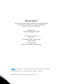
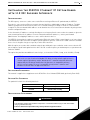
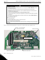
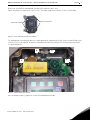
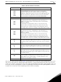
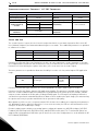
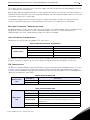
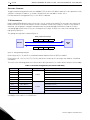
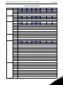
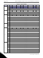
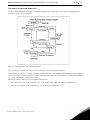
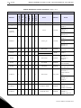
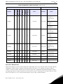
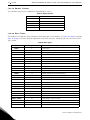
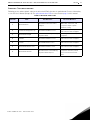
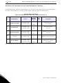
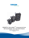
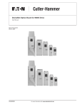
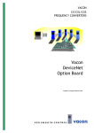
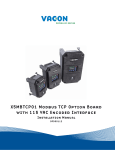
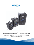
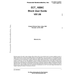
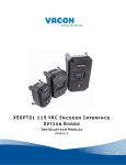
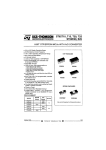
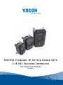
X5EIP01 Ethernet IP Option Board with
115 VAC Encoder Interface
Installation Manual
DPD00111
Need Help?
This manual answers most installation and startup questions
that may arise. However, if you have any problems,
please let your first call be to us.
Vacon, Inc.
Chambersburg, PA 17202
Normal business hours:
(North America)
8:00 AM to 5:00 PM, Eastern time
+1 877-Vacon06
(+1 877-822-6606)
After-hours support is also available
and Vacon, Inc. are trademarks of Vacon Plc, a member of Vacon Group.
All other product names are trademarks of their respective companies.
Copyright 2009, Vacon, Incorporated. All rights reserved.
X5EIP01 Ethernet IP with 115 VAC / Encoder Interface Option Board
vacon
3
Installing the X5EIP01 Ethernet IP Option Board
with 115 VAC Encoder Interface
Introduction
The X5 frequency converters can be connected to Ethernet using an Ethernet IP option board, the X5EIP01.
Every device connected to an Ethernet network has two identifiers: a MAC address and an IP address. The MAC
address (formatted as xx:xx:xx:xx:xx:xx, where xx is a hexadecimal byte) is unique to the device and cannot be
changed. The Ethernet board’s MAC address can be found on the sticker attached to the board or by using various
network configuration tools.
In a local network, IP addresses can be defined by a user as long as all units connected to the network are given the
same network portion of the address. For more information about IP addresses, contact your Network
Administrator. Overlapping IP addresses cause conflicts between devices.
The X5EIP01 also provides the option of controlling the X5 AC drive from 115 VAC control signals, or of connecting a
shaft-mounted encoder to the drive to improve speed regulation. Up to five channels of 115 VAC control are available
for use in selecting direction, preset speeds, or other drive functions.
With this option, an encoder with a nominal rating of up to 2048 pulses per revolution can be connected to the X5
unit to improve speed load regulation of the drive. Overall encoder frequency at maximum process speed must be
limited to 100kHz.
This option also provides two additional control relays, each rated for 115 VAC, 1 amp, or for 230 VAC, 0.5 amp.
NOTE: This network communication interface included with the X5 option is warranted
to meet the core specifications for Modbus TCP. Many existing software applications are
custom-engineered and may contain “brand-specific” communication that will not be
supported by the X5 without modification. No guarantee of compatibility with any
specific system is made. The user is responsible for any interface software and
hardware needed to make an application function.
Applicable Documents
This manual is supplied as a supplement to the X5 AC Drive User’s Manual (DPD 00089, previously Form 1434).
Option Kit Contents
The option kit includes the following materials:
Part Number
Description
25100067C
Ethernet IP Option Board
32100391
Flexible cable assembly
Installation Procedures
!
WARNING
SENSITIVE EQUIPMENT
This assembly contains static-sensitive components. It should be handled only by a static-safe installer,
using a grounded wrist strap.
Failure to observe this precaution may cause premature equipment failure.
Email: [email protected] • Fax 717-264-3115
4
X5EIP01 Ethernet IP with 115 VAC / Encoder Interface Option Board
vacon
!
DANGER
HAZARDOUS VOLTAGE
• Disconnect all power before servicing a drive unit or its components. WAIT 5 MINUTES until the DC
bus capacitors discharge.
• Ensure that any other power sources that may feed control logic have been disconnected.
• DO NOT short across DC bus capacitors or touch unshielded components or terminal strip screw
connections with voltage present.
• Install all covers before applying power or starting and stopping the drive.
• The user is responsible for conforming to all applicable code requirements with respect to grounding
all equipment.
• Many parts in a drive, including printed circuit boards, operate at line voltage. DO NOT TOUCH. Use
only electrically-insulated tools.
Before servicing any drive.
• Disconnect all power.
• Place a “DO NOT TURN ON” label on the drive disconnect.
• Lock the disconnect in the open position.
Failure to observe these precautions will cause shock or burn, resulting in severe personal injury
or death.
Figure 1 shows the option board and the location of the terminals and the power supply selector.
Encoder / 115 VAC Interface
Control Relay Terminals
Ethernet Connector
Encoder Interface Power
Supply Selector
Module Status LED
Network Status LED
Figure 1: Option Board Layout
24-hour support 1-877-822-6606
X5EIP01 Ethernet IP with 115 VAC / Encoder Interface Option Board
vacon
5
Before you can install the option board, you must first remove the drive cover.
Figure 2 shows the locations of the cover screws. The torque range for the X5 Size 1 cover is 18-26 in/lbs.
Cover screw locations
Cover screw locations
Figure 2: Cover Assembly and Screw Locations
The option board is installed just above the control board in all configurations (a Size 1 unit is shown in Figure 3 for
reference). The screws labeled “A” must be removed from the X5; those labeled “B” need only to be loosened to
accept the board slot.
.
B
B
A
Figure 3: Option Mounting Locations
Once the board is in place, tighten the screws to a maximum of 26 in-lbs.
Email: [email protected] • Fax 717-264-3115
A
6
vacon
X5EIP01 Ethernet IP with 115 VAC / Encoder Interface Option Board
Next, install the flexible circuit to finish the interface to the control board. (Refer to Figure 4.) To install the flexible
circuit, first remove the keypad frame (necessary in this size unit). The frame is attached with two screws in opposite
corners; the screws thread into fasteners in the plastic assembly. After the flexible circuit is installed, replace these
screws, limiting the installation torque to 12 in-lbs..
Figure 4: Flexible Circuit Interface to Control Board
115 VAC Interface / Relay / Encoder Interface Terminals
Figure 5: 115 VAC Interface / Encoder Terminals
The X5OPT01 option kit includes five 115 VAC inputs, two additional programmable relays, and an encoder interface.
The details of the terminals on the board related to the 115 VAC interface and the encoder are shown in Table 1 on
page 7:
24-hour support 1-877-822-6606
X5EIP01 Ethernet IP with 115 VAC / Encoder Interface Option Board
vacon
7
Table 1: Encoder Interface Terminals
Terminal
Description
DI-A
DI-B
DI-C
DI-D
DI-E
115 VAC logic input; connect input to 115 VAC to activate.
The programmable functionality of these inputs is controlled by
parameters 728, 729, 730, 731, and 732. Each of these inputs can be
disabled or configured to emulate the function of the FWD, REV, R/J, EN,
MOL, DI1, DI2, DI3, DI4, or DI5 input terminals on the X5 control board.
Refer to the X5 User’s Manual for more information (DPD 00089).
ACn
The neutral connection for the 115 VAC control inputs
NO3
RC3
NC3
The third auxiliary relay.
The function of this relay is set by parameter 709. Functionally, it is
capable of each of the features outlined in the X5 user manual under
parameters 705-708.
Terminal NO3 is a normally-open contact; it closes when the relay
activates. NC3 is a normally-closed contact; it opens when the relay
activates. RC3 is the common terminal associated with both contacts.
The ratings of these contacts are 115 VAC, 1 amp; and 230 VAC, 0.5 amp.
NO4
RC4
NC4
The fourth auxiliary relay.
The function of this relay is set by parameter 710. Functionally, it is
capable of each of the features outlined in the X5 user manual under
parameters 705-708.
Terminal NO4 is a normally-open contact; it closes when the relay
activates. NC4 is a normally-closed contact; it opens when the relay
activates. RC4 is the common terminal associated with both contacts.
The ratings of these contacts are 115 VAC, 1 amp; and 230 VAC, 0.5 amp.
A+
A-
Channel A input from the encoder. Compatible with line driver, open
collector, or totem pole outputs from an encoder. If it is an open collector
or totem pole-type, encoder outputs are used; connect the A- terminal to
Ecom.
B+
B-
Channel B input from the encoder. Compatible with line driver, open
collector, or totem pole outputs from an encoder. If it is an open collector
or totem pole-type, encoder outputs are used; connect the B- terminal to
Ecom.
C+
C-
Channel C input from the encoder, the home pulse. Compatible with line
driver, open collector, or totem pole outputs from an encoder. If it is an
open collector or totem pole-type, encoder outputs are used; connect the
C- terminal to Ecom.
VDC
Power supply terminal for use with a customer-supplied encoder. It can
be either +12 VDC or +5 VDC based on the position of the encoder interface
power supply selector shown in Figure 1. Voltage regulation: +/- 5%;
maximum current available is 100 mA.
Ecom
Signal common for the encoder interface
Note that the connections described in Table 1 work only when the encoder has an internal pull-up resistor on the
open collector. Alternatively, it might be preferable to pull the + channel high, and attach the open collector to the channel. For example, if using Channel A, A+ on the option board would be tied to VDC, and A- would be connected
to the open collector coming from the encoder. The advantage in this method is that no pull-up/down resistors are
needed; if the encoder has an internal pull-up, this does not affect anything.
Email: [email protected] • Fax 717-264-3115
8
X5EIP01 Ethernet IP with 115 VAC / Encoder Interface Option Board
vacon
Specifications for Encoder / 115 VAC Interface
Encoder Interface
Speed regulation
115 VAC Interface
< 0.1 Hz (1)
On state
Input frequency (max.)
100 kHz
Off state
< 10 VAC
Input voltage
10-24 VDC +/- 5%
Input frequency
58-62 Hz
Suggested pull-up
resistor
Terminal block wire
limitations
5 VDC
500 ohms
12 VDC
1k ohms
24 VDC
3.3k ohms
12-24 AWG
90-140 VAC
On/off delay
30 ms maximum
Terminal block wire
limitations
12-24 AWG
(1) PID feedback plus optimal motor turning in SLV mode employed
Setup and Use
The encoder interface is most effective if used in conjunction with the vector mode of operation. Refer to the X5
User’s Manual (Chapter 6) for information about using the vector mode. Three additional parameters are provided
to calibrate the encoder:
Parameter #
Parameter Name
Range
Default Value
219
Encoder Pulses per Revolution
0-16383
1024
220
Encoder Filter Time
10-1000 ms
20 ms
221
Encoder Speed Protection
0-20.0%
0%
Parameter 219, Encoder Pulses per Revolution, can either be extracted from the encoder nameplate or the data
sheet supplied with it. Parameter 220, Encoder Filter Time, is used to filter the encoder signal in the event of noise.
Parameter 221 is for limiting the response of the drive, in the event of the loss of encoder signal.
Two other parameters are provided to allow more flexibility in encoder selection, and to improve PID application
usage:
Parameter #
Parameter Name
Range
Default Value
EncoderType
Quadrature
or Single
Channel
Quadrature
223
224
Encoder Range
0-24000 rpm
0 rpm
Parameter 223, Encoder Type, allows the use of either quadrature or single-channel types of encoders.
Parameter 224, Encoder Range, improves PID application flexibility. This parameter should be used in situations
where the encoder feedback signal is not always directly proportional to the motor speed, for example, a winder
using an encoder mounted on an idler pulley feeding a winding spool. The PID may be attempting to maintain a
constant linear speed on the wound media, but as the diameter of the media on the spool changes, the motor turning
the spool needs to vary its speed to maintain the linear speed at the idler pulley.
When parameter 224 is set to 0, it is ignored, and the PID calculates the feedback percentage based on parameter
301, Maximum Frequency. When this parameter is set to a non-zero value, the PID uses instead Parameter 224’s
setting to calculate the feedback percentage.
Encoder feedback works similarly to an analog input as configured in parameters 850 (PID Configure), 851 (PID
Feedback), 852 (PID Prop Gain), 853 (PID Int Gain), and 859 (PID Derivative Gain). The “feed forward” options are
suggested for setting parameter 850. More specific details on each of the listed parameters can be found in the X5
User’s Manual (DPD 00089).
24-hour support 1-877-822-6606
X5EIP01 Ethernet IP with 115 VAC / Encoder Interface Option Board
vacon
9
The encoder interface can easily serve as one of the inputs to the X5’s Keeper Function (data logging). See the X5
User’s Manual for more information.
Both the Vmet and Imet output from the drive can be configured to indicate the status of the encoder. Parameters
700 (Vmet) and 702 (Imet) that relate to the setup and calibration of the Vmet and Imet outputs, both have selections
related to the status of the encoder input.
The Program Sequencer function can also key off the encoder’s home pulse. To make use of this function, the
encoder’s home pulse (1 pulse per revolution) must be connected to the C- input of the encoder board.
Encoder Interface Troubleshooting
Any problem with the encoder interface will result in an F37 fault. Four advanced fault codes are available to help
you determine whether you have an encoder calibration problem, or a defect. For more information on
troubleshooting, refer to the Troubleshooting chapter in the X5 User’s Manual.
Using Ethernet Connections
Following are the specifications for Modbus / TCP connections:
Table 2: Ethernet Connection Specifications
Connections
Communications
Interface
RJ-45 Connector
Transfer cable
Foiled CAT5e
Speed
10 / 100 Mb
Duplex
half/full
Default IP address
0.0.0.0
To communicate with the drive over Ethernet, the drive’s IP address must be set. This is done with parameters 922925. After setting the IP address, be sure to cycle power off and back on for the new address to take effect.
LED Indications
The Ethernet / IP Option Board includes two LED status indicators: Network Status and Module Status. See Figure
1 on page 4 for the location of these LEDs on the board. Network status provides information on the network
connection status and Module status provides information on the Ethernet / IP module itself. The following tables
explain the meaning of the status LEDs:
Table 3: Network Status LED
If the LED is...
Network Status
LED
This means...
OFF
There is no power applied to the option board.
Red
The option board cannot communicate on the network.
Table 4: Module Status LED
If the LED is...
OFF
Green
Module Status
LED
Green (flashing)
Red (flashing)
Red
Email: [email protected] • Fax 717-264-3115
This means...
There is no power applied to the option board.
The option board is operating normally.
The option board is in Standby state or the device needs
commissioning because of a missing, incomplete, or incorrect
configuration.
The option board has detected a recoverable fault.
The option board has detected an unrecoverable fault.
10
X5EIP01 Ethernet IP with 115 VAC / Encoder Interface Option Board
vacon
Getting Started
To begin communicating with the drive over Modbus / TCP, the drive’s IP address must be set (use parameters 922925). After setting the IP address, cycle power off and on for the new address to take effect.
For information on setting parameters, see the X5 User’s Manual.
I/O Messaging
Input / Output (I/O) polling messages are for time-critical, control-oriented data. The messages are transferred
between the devices all the time and are used for continuous control of the frequency converter. They provide a
dedicated, special-purpose communication path between a producing application (master) and one or more
consuming applications (slaves). They are exchanged across single- or multi-cast connections and typically use
high-priority identifiers.
The polling message flow is shown in Figure 6.
Data (Output Assembly)
Slave
X5
Master
Data (Input Assembly)
Figure 6: Polling Message Diagram
I/O messages 20, 21, 70, and 71 are standard Common Industrial Protocol (CIP) assemblies.
I/O messages 121, 122, 131, 132, 171, 172, 181, and 182 are vendor-specific messages that allow for customized
assemblies.
The values of the following parameters indicate which drive parameters are read or written to by the I/O assembly:
Table 5: Parameter Assignments (Parameters 880-894)
Parameter #
Parameter Name
880
FBus Read 1
Range
103 (Output Voltage)
881
FBus Read 2
104 (Output Current)
882
FBus Read 3
0-65535
Default
105 (Drive Load)
883
FBus Read 4
107 (Drive Temp)
884
FBus Read 5
909 (DI Status)
890
FBus Write 1
103 (Output Voltage)
891
FBus Write 2
104 (Output Current)
892
FBus Write 3
893
FBus Write 4
107 (Drive Temp)
894
FBus Write 5
909 (DI Status)
0-65535
105 (Drive Load)
Examples 1 and 2 on the following pages show how using the FBus Write 2 = Parameter 402 would allow the I/O
assembly to set the drive’s acceleration rate.
24-hour support 1-877-822-6606
X5EIP01 Ethernet IP with 115 VAC / Encoder Interface Option Board
vacon
Example 1: Output Assemblies
Instance
Byte
Bit 7
Bit 6
Bit 5
0
20
Bit 3
Bit 2
Bit 1
Fault Reset
Bit 0
Run Fwd
1
2
Speed Reference (low byte)
3
Speed Reference (high byte)
0
21
Bit 4
NetRef
NetCtrl
Fault Reset
Run Rev
Run Fwd
Run Rev
Run Fwd
Run Rev
Run Fwd
1
2
Speed Reference (low byte)
3
0
Speed Reference (high byte)
NetRef
NetCtrl
Fault Reset
1
121
122
2
Speed Reference (low byte)
3
Speed Reference (high byte)
4
FBus Write1 (low byte)
5
FBus Write1 (high byte)
6
FBus Write2 (low byte)
7
FBus Write2 (high byte)
0
FBus Write1 (low byte)
1
FBus Write1 (high byte)
2
FBus Write2 (low byte)
3
FBus Write2 (high byte)
0
NetRef
NetCtrl
Fault Reset
1
131
132
2
Speed Reference (low byte)
3
Speed Reference (high byte)
4
FBus Write1 (low byte)
5
FBus Write1 (high byte)
6
FBus Write2 (low byte)
7
FBus Write2 (high byte)
8
FBus Write3 (low byte)
9
FBus Write3 (high byte)
10
FBus Write4 (low byte)
11
FBus Write4 (high byte)
12
FBus Write5 (low byte)
13
FBus Write5 (high byte)
0
FBus Write1 (low byte)
1
FBus Write1 (high byte)
2
FBus Write2 (low byte)
3
FBus Write2 (high byte)
4
FBus Write3 (low byte)
5
FBus Write3 (high byte)
6
FBus Write4 (low byte)
7
FBus Write4 (high byte)
8
FBus Write5 (low byte)
9
FBus Write5 (high byte)
Email: [email protected] • Fax 717-264-3115
11
12
X5EIP01 Ethernet IP with 115 VAC / Encoder Interface Option Board
vacon
Example 2: Input Assemblies
Instance
Byte
Bit 7
Bit 6
Bit 5
Bit 4
Bit 3
0
70
Running 1 (Fwd)
2
0
172
Ref from Net
Ctrl from Net
Ready
Running 2 (Rev)
Speed Actual (low byte)
3
Speed Actual (high byte)
At Ref
Ref from Net
Ctrl from Net
Ready
Running 2 (Rev)
1
Drive State
2
Speed Actual (low byte)
3
Speed Actual (high byte)
4
FBus Read1 (low byte)
5
FBus Read1 (high byte)
6
FBus Read2 (low byte)
7
FBus Read2 (high byte)
0
FBus Read1 (low byte)
1
FBus Read1 (high byte)
2
FBus Read2 (low byte)
1
Ref from Net
Ctrl from Net
Ready
Running 2 (Rev)
Faulted
Running 1 (Fwd)
Warning
Faulted
Running 1 (Fwd)
Warning
Faulted
Drive State
Speed Actual (low byte)
3
Speed Actual (high byte)
4
FBus Read1 (low byte)
5
FBus Read1 (high byte)
6
FBus Read2 (low byte)
7
FBus Read2 (high byte)
8
FBus Read3 (low byte)
9
FBus Read3 (high byte)
10
FBus Read4 (low byte)
11
FBus Read4 (high byte)
12
FBus Read5 (low byte)
13
FBus Read5 (high byte)
0
FBus Read1 (low byte)
1
FBus Read1 (high byte)
2
FBus Read2 (low byte)
3
FBus Read2 (high byte)
5
Warning
FBus Read2 (high byte)
At Ref
2
4
Running 1 (Fwd)
Drive State
2
0
182
Faulted
Speed Actual (high byte)
At Ref
3
181
Bit 0
Speed Actual (low byte)
1
0
171
Bit 1
1
3
71
Bit 2
FBus Read3 (low byte)
FBus Read3 (high byte)
6
FBus Read4 (low byte)
7
FBus Read4 (high byte)
8
FBus Read5 (low byte)
9
FBus Read5 (high byte)
24-hour support 1-877-822-6606
X5EIP01 Ethernet IP with 115 VAC / Encoder Interface Option Board
vacon
13
Control Supervisor Behavior
The State Transition diagram in Figure 7 provides a graphical description of the states and corresponding state
transitions for the control supervisor.
Figure 7: Control Supervisor State Transition Diagram
Table 6 on page 14 explains the state transitions pictured in the flow diagram in Figure 7.
Start Forward, Start Reverse, Change to Forward, Change to Reverse, and Stop (Not Faulted Stop) are static outputs
of the control supervisor state machine. They are commands to the drive when CtrlFromNet = 1. When CtrlFromNet
= 0, control commands are from another source.
When performing changes to achieve programmed Safe State:
•
Run / Stop / Direction can be changed because CtrlFromNet must equal 1 when in the Enabled state.
•
Reference in the drive can be changed to Preset Speed only if RefFromNet = 1.
Email: [email protected] • Fax 717-264-3115
X5EIP01 Ethernet IP with 115 VAC / Encoder Interface Option Board
vacon
Table 6: Explanation of State Transitions (Page 1 of 2)
Fwd Mode
Rev Mode
x
Idle Mode
x
Run 2 (Rev)
Old State
Results
Run1 (Fwd)
Input Conditions
CtrlFromNet
14
x
x
x
x
x
Event
New State
Power_Off
NonExist
Action
Faulted = 0
Ready = 0
x
x
x
x
x
x
x
Reset
Startup
(except
NonExist)
FwdMode = 0
RevMode = 0
Run1 Var = 0
Run2 Var = 0
Faulted = 0
Ready = 0
NonExist
x
x
x
x
x
x
Power_On
Startup
FwdMode = 0
RevMode = 0
Run1 Var = 0
Run2 Var = 0
x
x
x
x
x
x
Startup
x
x
x
x
x
x
Ready
x
x
x
x
x
x
Drive Fault
Faulted
Faulted = 1
FaultCode = x
Ready = 0
Ready
1
1
0
0
x
x
Run (Fwd)
Enabled
FwdMode = 1
(Start Forward)
Ready
1
0
1
0
x
x
Run (Rev)
Enabled
RevMode = 1
(Start Reverse)
Enabled
x
x
x
x
x
x
Drive Fault
Initialization
Complete
Drive Fault
Faulted
Faulted = 1
FaultCode = x
Startup
Ready
Fault_Stop
Ready = 1
Faulted = 1
FaultCode = x
(Initiate Faulted
Stop)
FwdMode = 0
RevMode = 0
Ready = 0
Enabled
1
0
0
x
x
x
Stop
Stopping
(Initiate Stop)
Enabled
1
1
0
0
0
1
ChangeDir (Fwd)
Enabled
FwdMode = 1
RevMode = 0
(Change to Forward)
Enabled
1
0
1
0
1
0
ChangeDir (Rev)
Enabled
FwdMode = 0
RevMode = 1
(Change to Reverse)
24-hour support 1-877-822-6606
X5EIP01 Ethernet IP with 115 VAC / Encoder Interface Option Board
vacon
15
Table 6: Explanation of State Transitions (Page 2 of 2)
Results
Rev Mode
Fwd Mode
Idle Mode
Run 2 (Rev)
Old State
Run1 (Fwd)
CtrlFromNet
Input Conditions
Event
New State
Action
Faulted = 1
FaultCode = x
(Initiate Faulted
Stop)
Enabled
1
x
x
x
x
x
SafeFault
Fault_Stop
FwdMode = 0
RevMode = 0
Ready = 0
Run1 Var = 0
Run2 Var = 0
FwdMode =
Run1 Var =
NOT PresetDir
Enabled
1
x
x
x
x
x
SafeChange
Enabled
RevMode = 0
Run2 Var =
PresetDir
SpeedRef =
Preset Speed
TorqueRef =
Preset Torque
Stopping
x
x
x
x
x
x
Drive Fault
Fault_Stop
Faulted = 1
FaultCode = x
(Initiate Faulted
Stop)
Ready = 0
Stopping
1
1
0
0
x
x
Run (Fwd)
Enabled
FwdMode = 1
(Start Forward)
Stopping
1
0
1
0
x
x
Run (Rev)
Enabled
RevMode = 1
(Start Reverse)
Stopping
x
0
0
x
x
x
Stop_Complete
Ready
Fault_Stopped
x
x
x
x
x
x
Fault_Stop_ Complete
Faulted
Faulted
x
x
x
x
x
x
Fault_Reset
Ready
Faulted = 0
Ready = 1
Explicit Messaging
Explicit Messaging is used in commissioning and configuring the Ethernet / IP board. Explicit messages provide
multipurpose, point-to-point communication paths between two devices. They provide the typical request /
response-oriented network communication used to perform node configuration and problem diagnosis. Explicit
messages typically use low-priority identifiers and contain the specific meaning of the message right in the data
field. This includes the service to be performed and the specific object attribute address.
Email: [email protected] • Fax 717-264-3115
16
X5EIP01 Ethernet IP with 115 VAC / Encoder Interface Option Board
vacon
List of Object Classes
The Communication Interface supports the following object classes:
Table 7: Object Classes
Class
Object
0x28
Motor Data
0x29
Control Supervisor
0x2A
AC/DC Drive
0x2B
Acknowledge Handler
0x65
Parameter
List of Data Types
The attribute list in Table 8 includes information on the data type of each attribute. See Table 10 on page 18 through
Table 13 on page 21 for more detailed explanations of the Data, Structure, and Array Type codes used in the Data
Type column.
Table 8: Data Types
Data Type Name
Data Type Code
WORD
1
16-bit word
Data Type Description
UINT
2
16-bit unsigned integer
INT
3
16-bitsigned integer
BOOL
4
Boolean
SINT
5
Short integer
DINT
6
Double integer
LINT
7
Long integer
USINT
8
Unsigned short integer
UDINT
9
Unsigned double integer
ULINT
10
Unsigned long integer
REAL
11
Single floating-point format (IEEE 754)
LREAL
12
Double floating-point format (IEEE 754)
ITIME
13
Duration (short)
TIME
14
Duration
FTIME
15
Duration (high resolution)
LTIME
16
Duration (long)
DATE
17
Date (see Ethernet/IP spec)
TIME_OF_DAY
18
Time of day
DATE_AND_TIME
19
Date and time
STRING
20
8-bit-per-character string
STRING2
21
16-bit-per-character string
STRINGN
22
N-bytes-per-character string
SHORT_STRING
23
Short N-byte character string
BYTE
24
8-bit string
DWORD
25
32-bit string
LWORD
26
64-bit string
24-hour support 1-877-822-6606
X5EIP01 Ethernet IP with 115 VAC / Encoder Interface Option Board
vacon
17
Ethernet Troubleshooting
Following are the advanced fault codes for the drive fault (F38) related to the option board. For more information,
see the X5 User’s Manual (Chapter 8). The option board status LEDs are described on page 9 of this manual.
Table 9: Advanced Fault Codes
Advanced
Fault Code
Fault
Possible Cause
Corrective Measures
Check option board status LEDs,
ribbon cable connection, and
cycle power. Replace option
board if necessary.
1
Option board loss
Option board is disconnected or
damaged
2
Unstable ID during power-up
Option board hardware issues
Cycle power. If problem persists,
contact Vacon technical support.
3
Option board changed
Option board was changed during
last power-down
If the change was intentional,
cycle power.
4
Invalid ID
Option board hardware issues
Cycle power. If problem persists,
contact Vacon technical support.
5
Wrong or no daughter card
installed
Option DIMM module issues
Cycle power. If problem persists,
contact Vacon technical support.
6
Option board software error
Option board software issues
Cycle power. If problem persists,
contact Vacon technical support.
Option board removed
Option board was removed during
last power-down sequence
If the change was intentional,
cycle power. Otherwise, follow
corrective measures for fault
code 1.
7
Email: [email protected] • Fax 717-264-3115
18
X5EIP01 Ethernet IP with 115 VAC / Encoder Interface Option Board
vacon
Appendix: X5 Communication Interface Object Profiles
In the following tables, attributes shown in bold face are stored in the non-volatile part of the drive and maintain
their values after a power loss. All other settable attributes will power up at their default values.
Table 10: Motor Data Object
(Class Code 0x28, Motor Data Class (40) - Instance Attributes (1)
Attribute Name
Services
Default,
Minimum,
Maximum
(1)
6
0x06
RatedCurrent[100mA]
Get_Attribute_Single
Set_Attribute_Single
360
0
65535
2
Rated Stator Current
Units: [100mA]
7
0x07
RatedVoltage[V]
Get_Attribute_Single
Set_Attribute_Single
230
100
690
2
Rated Base Voltage
Units: [V]
9
0x09
RatedFrequency[Hz]
Get_Attribute_Single
Set_Attribute_Single
60
0
400
2
Rated Electrical Frequency
Units: [Hz}
12
0x0C
PoleCount
Get_Attribute_Single
2
2
16
2
Number of poles in the motor
BaseSpeed[RPM]
Get_Attribute_Single
Set_Attribute_Single
1760
1
24000
2
Nominal speed at rated
frequency from nameplate
Units: [RPM]
#
15
0x0F
Data
Type
Description
(1) The default value shown in this column is model-dependent.
24-hour support 1-877-822-6606
X5EIP01 Ethernet IP with 115 VAC / Encoder Interface Option Board
vacon
Table 11: Control Supervisor Object
(Class Code 0x29, Control Supervisor Class (41) - Instance Attributes (1)
#
Attribute Name
Services
Default,
Minimum,
Maximum
Data
Type
Description
3
0x03
Run1
Get_Attribute_Single
Set_Attribute_Single
0
0
1
4
Run Forward Request
4
0x04
Run2
Get_Attribute_Single
Set_Attribute_Single
0
0
1
4
Run Reverse Request
5
0x05
NetCtrl
Get_Attribute_Single
Set_Attribute_Single
0
0
1
4
Requests Run/Stop control to be
local or from network
6
0x06
State
Get_Attribute_Single
N/A
0
7
8
State of Control Supervisor Instance:
1 = Startup
2 = Not_Ready
3 = Ready
4 = Enabled
5 = Stopping
6 = Fault_Stop
7 = Faulted
7
0x07
Running1
Get_Attribute_Single
N/A
0
1
4
Running Forward Status:
0 = Other state
1 = Running Forward
8
0x08
Running2
Get_Attribute_Single
N/A
0
1
4
Running Reverse Status:
0 = Other state
1 = Running Reverse
4
Ready to Accept a Run Event:
0 = Other state
1 = Ready to accept a Run event
4
Fault Occurred:
0 = No faults present
1 = Fault occurred (latched)
4
Fault Reset Request:
0 = No action
0 -> 1 = Fault reset request
1 = No action
9
0x09
Ready
Get_Attribute_Single
N/A
0
1
10
0x0A
Faulted
Get_Attribute_Single
N/A
0
1
FaultRst
Get_Attribute_Single
Set_Attribute_Single
0
0
1
2
If in faulted state, FaultCode
indicates the fault that caused the
transition to be in a faulted state. The
fault codes are listed in the Ethernet/
IP specifications
4
Status of Run / Stop control source:
0 = Control is local
1 = Control is from the network
12
0x0C
13
0x0D
FaultCode
Get_Attribute_Single
N/A
0
65535
15
0x0F
CtrlFromNet
Get_Attribute_Single
N/A
0
1
Email: [email protected] • Fax 717-264-3115
19
20
X5EIP01 Ethernet IP with 115 VAC / Encoder Interface Option Board
vacon
Table 12: AC/DC Drive Object
(Class Code 0x2A, AC/DC Drive Class (42) - Instance Attributes (1)
#
Attribute Name
Services
Default,
Minimum,
Maximum
Data
Type
Description
3
0x03
AtReference
Get_Attribute_Single
N/A
0
1
4
1 = Drive actual at speed reference
4
0x04
NetRef
Get_Attribute_Single
Set_Attribute_Single
0
0
1
4
Requests speed reference to be local
or from the network:
0 = Set Reference to local control
1 = Set Reference to DN control
Note that the actual status of torque
or speed reference is reflected in
attribute 29, RefFromNet.
6
0x06
DriveMode
Get_Attribute_Single
1
1
1
8
1 = Open loop speed (Frequency)
7
0x07
SpeedActual(RPM)
Get_Attribute_Single
N/A
0
10000
3
Actual drive speed (best
approximation)
Units: RPM
8
0x08
SpeedRef[RPM}
Get_Attribute_Single
Set_Attribute_Single
1800
0
12000
3
Speed reference
Units: RPM
3
Actual motor phase current
Units: 100mA
9
0x09
CurrentActual[100mA)
Get_Attribute_Single
N/A
0
1000
17
0x11
OutputVoltage[V]
Get_Attribute_Single
N/A
0
690
3
Output Voltage
Units: Volts
18
0x12
AccelTime[100ms]
Get_Attribute_Single
Set_Attribute_Single
30
1
32000
2
Acceleration time
Time from 0 to HighSpdLimit
Units: 100ms
19
0x13
DecelTime[100 ms]
Get_Attribute_Single
Set_Attribute_Single
30
1
32000
2
Deceleration time
Time from HighSpdLimit to 0
Units: 100ms
20
0x14
LowSpdLimit[RPM]
Get_Attribute_Single
Set_Attribute_Single
0
0
12000
2
Minimum speed limit
Units: RPM
21
0x15
HighSpdLimit[RPM]
Get_Attribute_Single
Set_Attribute_Single
1800
0
12000
2
Maximum speed limit
Units: RPM
29
0x1D
RefFromNet
Get_Attribute_Single
N/A
0
1
4
Status of speed reference:
0 = Local speed reference
1 = Ethernet / IP speed reference
24-hour support 1-877-822-6606
X5EIP01 Ethernet IP with 115 VAC / Encoder Interface Option Board
vacon
Table 13: Parameter Object
(Class Code 0x65, Parameter Class (101) - Class Attributes (1-999)
#
1
0x01
Attribute Name
N/A
Services
Get_Attribute_Single
Set_Attribute_Single
Email: [email protected] • Fax 717-264-3115
Default,
Minimum,
Maximum
N/A
N/A
N/A
Data
Type
Description
2
These instances give direct access to
all drive parameters where the
instance number corresponds to the
parameter number. See the X5
User’s Manual (Ch. 7) for more
information on specific drive
parameters.
21
head office and production:
Vaasa
Vacon Plc
Runsorintie 7
65380 Vaasa
[email protected]
telephone: +358 (0)201 2121
fax: +358 (0)201 212 205
production:
Suzhou, China
Vacon Suzhou Drives Co. Ltd.
Building 11A
428# Xinglong Street, SIP
Suchun Industrial Square
Suzhou 215126
telephone: + 86 512 62836630
fax: + 86 512 62836618
Naturno, Italy
Vacon S.R.I
Via Zone Industriale, 11
39025 Naturno
production:
Chambersburg, USA
3181 Black Gap Road
Chambersburg, PA 17202
TB Wood's (India) Pvt. Ltd.
#27, 'E' Electronics City
Hosur Road
Bangalore - 560 100
India
Tel. +91-80-30280123
Fax. +91-80-30280124
sales companies and representative offices:
finland
Helsinki
Vacon Plc
Äyritie 8
01510 Vantaa
telephone: +358 (0)201 212 600
fax: +358 (0)201 212 699
Tampere
Vacon Plc
Vehnämyllynkatu 18
33580 Tampere
telephone: +358 (0)201 2121
fax: +358 (0)201 212 750
australia
Vacon Pacific Pty Ltd
5/66-74, Micro Circuit
Dandenong South, VIC 3175
telephone: +61 (0)3 9238 9300
fax: +61 (0)3 92389310
austria
Vacon AT Antriebssysteme GmbH
Aumühlweg 21
2544 Leobersdorf
telephone: +43 2256 651 66
fax: +43 2256 651 66 66
belgium
Vacon Benelux NV/SA
Interleuvenlaan 62
3001 Heverlee (Leuven)
telephone: +32 (0)16 394 825
fax: +32 (0)16 394 827
brazil
Vacon Brazil
Alameda Mamoré, 535
Alphaville - Barueri -SP
Tel. +55 11 4166-5707
Fax. +55 11 4166-5567
canada
Vacon Canada
221 Griffith Road
Stratford, Ontario N5A 6T3
telephone: +1 (519) 508-2323
fax: +1 (519) 508-2324
china
Vacon Suzhou Drives Co. Ltd.
Beijing Branch
A528, Grand Pacific Garden Mansion
8A Guanghua Road
Beijing 100026
telephone: + 86 10 51280006
fax: +86 10 65813733
czech republic
Vacon s.r.o.
Kodanska 1441/46
110 00 Prague 10
telephone: +420 234 063 250
fax: +420 234 063 251
france
Vacon France
ZAC du Fresne
1 Rue Jacquard - BP72
91280 Saint Pierre du Perray CDIS
telephone: +33 (0)1 69 89 60 30
fax: +33 (0)1 69 89 60 40
germany
Vacon GmbH
Gladbecker Strasse 425
45329 Essen
telephone: +49 (0)201 806 700
fax: +49 (0)201 806 7099
slovakia
Vacon s.r.o. (Branch)
Seberiniho 1
821 03 Bratislava
Tel. +421 243 330 202
Fax. +421 243 634 389
Vacon OEM Business Center GmbH
Industriestr. 13
51709 - Marienheide
Germany
Tel. +49 02264 17-17
Fax. +49 02264 17-126
spain
Vacon Drives Ibérica S.A.
Miquel Servet, 2. P.I. Bufalvent
08243 Manresa
telephone: +34 93 877 45 06
fax: +34 93 877 00 09
india
Vacon Drives & Control Plc
Plot No 352
Kapaleeshwar Nagar
East Coast Road
Neelangarai
Chennai-600041
Tel. +91 44 244 900 24/25
sweden
Vacon AB
Anderstorpsvägen 16
171 54 Solna
telephone: +46 (0)8 293 055
fax: +46 (0)8 290 755
italy
Vacon S.p.A.
Via F.lli Guerra, 35
42100 Reggio Emilia
telephone: +39 0522 276811
fax: +39 0522 276890
the netherlands
Vacon Benelux BV
Weide 40
4206 CJ Gorinchem
telephone: +31 (0)183 642 970
fax: +31 (0)183 642 971
norway
Vacon AS
Bentsrudveien 17
3080 Holmestrand
telephone: +47 330 96120
fax: +47 330 96130
romania
Vacon Romania - Reprezentanta
Cuza Voda 1
400107 Cluj Napoca
Tel. +40 364 118 981
Fax. +40 364 118 981
russia
ZAO Vacon Drives
Ul. Letchika Babushkina 1,
Stroenie 3
129344 Moscow
telephone: +7 (495) 363 19 85
fax: +7 (495) 363 19 86
ZAO Vacon Drives
2ya Sovetskaya 7, office 210A
191036 St. Petersburg
telephone: +7 (812) 332 1114
fax: +7 (812) 279 9053
thailand
Vacon South East Asia
335/32 5th-6th floor
Srinakarin Road, Prawet
Bangkok 10250
Tel. +66 (0)2366 0768
ukraine
Vacon Drives Ukraine (Branch)
42-44 Shovkovychna Str.
Regus City Horizon Tower
Kiev 01601, Ukraine
Tel. +380 44 459 0579
Fax +380 44 490 1200
united arab emirates
Vacon Middle East and Africa
Block A, Office 4A 226
P.O.Box 54763
Dubai Airport Free Zone
Dubai
Tel. +971 (0)4 204 5200
Fax: +971 (0)4 204 5203
united kingdom
Vacon Drives (UK) Ltd.
18, Maizefield
Hinckley Fields Industrial Estate
Hinckley
LE10 1YF Leicestershire
telephone: +44 (0)1455 611 515
fax: +44 (0)1455 611 517
united states
Vacon, Inc.
3181, Black Gap Road
Chambersburg, PA 17202
telephone: +1 (877) 822-6606
fax: +1 (717) 267-0140