1
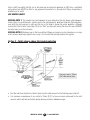
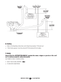
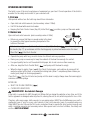
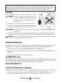
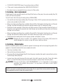
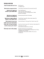
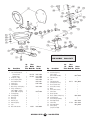
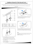
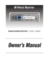
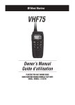
COMPACT MANUAL HEAD MODEL 14974265
Toilette compacte manuelle
Owner’s Manual
INSTALLATION INSTRUCTIONS
The West Marine Compact Manual Head is just one part of a system. Correct installation of the whole
system is essential if you want the toilet to perform properly, operate reliably and safely, and give satisfactory length of life. The toilet is delivered assembled for right- handed operation. If you wish,your head
may be re-assembled with the pump on the left hand side. The seat and lid is delivered boxed and
unfitted for its protection.
NOTE: Key numbers, e.g. (‘Key 31’), are references to the exploded view diagram on the back page.
1. Re-assembly for left hand use
If you wish to change the pump mounting from right to left hand, do so before installing the toilet.
• Pull off the hose (Key 4) that runs from the pump to the bowl.
• Remove the 4 screws (Key 31) that secure the pump assembly to the base.
• Lift off the pump assembly and leave the base valve gasket (Key 16) on its 3 locating pegs.
• Remove the 4 bolts (Key 11) that secure the bowl to the base.
• Rotate the bowl 180° and re-secure it, using the nylon washers (Key 14) to protect the ceramic from
the stainless steel washers and nuts (Key 13,12).
• Rotate the pump assembly 180° and re-secure it.
• Rotate the push-fit intake elbow (key 6) 180° and refit the hose between the pump and the bowl.
2. Location
• Select a location that will give sufficient clearance all round and above the toilet. Ensure that there
is room to operate the pump and that there is access to the drain plug at the end of the base.
• The mounting surface must be flat, rigid and strong enough to support a man’s weight and should
be at least 50mm (2") wider and 50mm (2") deeper than the base of the toilet.
• You will need sufficient clearance below the mounting surface to be able to secure the mounting bolts.
• The seat and lid should be able to swing up and over at least 110°, so that they will not fall forward
when the craft heels or pitches. When they are swung up they must be supported so that the hinges
are not strained.
3. Mounting
You will need:
• 4 x 8mm (5/16") diameter stainless steel bolts of length to suit the thickness of the mounting surface.
• 4 stainless steel nuts, preferably self-locking. If you do not use self-locking nuts you will need some
nut-locking compound.
• 8 large stainless steel washers not more than 21mm (13/16") diameter.
• A small tube of white silicone sealant.
MANUAL HEAD
2
1-800-BOATING
• Offer up the toilet in the selected position and, using the holes in the base as a guide, mark the
positions for the 4 bolt holes on the mounting surface. Remove the toilet and drill 4 vertical holes of
9mm diameter through the mounting surface.
• Apply a bead of white silicone sealant to the outer rim of the bottom base.
• Bolt down the toilet and tighten the fastenings securely. If you are not using self-locking nuts, use
nut-locking compound.
4. Through Hull Fittings
You will need:
• 19mm (3/4") bore seacock for the flushing water inlet, and, if you are discharging the waste
overboard, a 38mm (11/2") bore seacock for the waste outlet.
• Follow the seacock manufacturer’s own instructions concerning materials and methods of
installation.
• Ensure the inlet seacock is positioned where it will be below the waterline at all times when the craft is
underway, and also ensure that any outlet seacock is both aft of, and higher than, the inlet seacock.
HAZARD RISK Through Hull Fittings
If the installation of the toilet results in it being connected to ANY through-hull fitting that may possibly
be below the waterline at ANY time, whether when the craft is at rest, underway and heeling or rolling
or pitching, you must install the toilet in accordance with these Installation Instructions. If you do not,
water may flood in, causing the craft to sink, which may result in loss of life.
HAZARD RISK Accidental Damage
If the toilet is connected to ANY through-hull fittings and if the toilet or pipework is damaged, water may
flood in causing the craft to sink, which may result in loss of life.
Therefore, if you are making connections between the toilet and ANY through-hull fittings that may
possibly be below the waterline at ANY time, full bore seacocks MUST be fitted to those hull fittings, to
allow them to be shut off.
The seacocks MUST also be positioned where they are easily accessible to all users of the toilet. If, for
any reason, it is not possible to do this, then secondary full bore marine quality valves MUST be fitted
to the hoses where they are easily accessible.
ALWAYS USE SEACOCKS!
CAUTION: Use lever operated, full bore marine seacocks and valves.
The use of screw-down gate valves is not recommended.
5. Pipework
Select the correct method:
There are two (2) options for the inlet pipework, and four (4) options for the outlet pipework. It is critical
that you select the correct method according to whether the toilet is above or below the waterline, and
to whether it discharges the waste overboard or into an on-board holding tank.
MANUAL HEAD
3
1-800-BOATING
HAZARD RISK Pipework Becomes Loose
If the toilet is connected to ANY through-hull fittings and if the pipework becomes disconnected, either
from a through-hull fitting or seacock, or from the toilet or any secondary valve, water may flood in and
may cause the craft to sink, which may result in loss of life.
Therefore the ends of ALL flexible hoses fitted directly or indirectly between the toilet and ANY throughhull fitting that may possibly be below the waterline at ANY time, MUST be secured to the hose tails to
which they are connected, using two stainless steel worm-drive hose clips.
USE HOSE CLIPS!
5.1 Pipework
General instructions for all options
You will need:
• Spiral reinforced smooth bore flexible hoses for both the 19mm (3/4") id inlet and the 38mm
(1-1/2") id outlet pipework
• Two stainless steel worm-drive hose clips for every hose tail connection (4, 6 or 8).
• Secure the hose runs so hoses cannot move and chafe, and so that they do not exert any leverage
on the hose tail fittings to which they are connected, as this may cause adjacent joints to leak.
• Avoid sharp bends in the hoses that may cause them to become kinked.
• Keep all pipework lengths as short as possible, whilst complying with these instructions.
Unnecessary inlet or outlet hose length just makes the toilet harder to pump.
• If it is difficult to fit the hose onto the hose tails of the toilet or seacocks, lubricate it with water, or
soften the hose by dipping the end of it in hot water.
CAUTION: Do not apply flame to the hose. Do not apply flame or any heat to the plastic hose tails
on the toilet. Do not use oils, greases or synthetic lubricants. Do not apply sealing
compounds to any hose connections. Do not over tighten hose clips. Any of these
actions may result in cracking or breakage of the plastic parts of the toilet.
• Secure the ends of all hoses to the hose tails with two stainless steel worm-drive hose clips,
ensuring that all inlet connections are airtight and that all outlet connections are watertight.
• The Discharge Elbow (Key 34) may be rotated 360° to suit your installation. Always slacken the two
(2) securing screws, adjust the discharge elbow to the required position and re-tighten the two (2)
securing screws BEFORE you connect the hose to it.
CAUTION: Failure to follow this procedure may result in leaks between the discharge elbow and
the pump cylinder.
MANUAL HEAD
4
1-800-BOATING
5.2 Inlet Pipework: Two (2) Options
Option 1 - Toilet below the waterline
You must fit a 19mm (3/4")
Vented Loop fitting.
• Run the inlet hose by the most direct route from the inlet seacock to the flushing pump inlet tail.
• Remove the white hose supplied with the toilet, which connects the flushing pump outlet tail to the
elbow (Key 6).
• Rotate the intake seal (Key 5) so that the elbow points upwards.
• Replace the white hose with a longer length of 19mm (3/4") id hose and arrange it to form an anti
syphon loop whose highest point is at least 20cm (8") above the highest possible waterline, and fit
the Vented Loop at the highest point.
• Secure the ends of all hoses with two stainless steel worm-drive hose clips.
CAUTION: Do not position the ventilated anti-syphon loop between the inlet seacock and the
flushing pump inlet, as it will make the flushing pump difficult to prime, harder to pump
and may prevent it from working at all.
HAZARD RISK Bowl Rim Below Waterline
If the toilet is connected to ANY through-hull fittings, and if the rim of the bowl falls below the waterline,
water may flood in causing the craft to sink, which may result in loss of life.
Therefore, if the rim of the toilet is less than 20cm (8") above the waterline when the craft is at rest, or if
MANUAL HEAD
5
1-800-BOATING
there is ANY possibility that the rim of the bowl may be below the waterline at ANY time, a ventilated
anti-syphon loop MUST be fitted in any pipework connected to a through-hull fitting, irrespective of
whether inlet or outlet.
USE VENTED LOOPS!
SPECIAL NOTE 1: The smaller bore inlet pipework is more hazardous than the larger outlet pipework.
Unless there is a ventilated anti- syphon loop in the inlet pipework, water will flow into the bowl whenever both the inlet seacock is open and the rim of the bowl is below the actual waterline. Although
moving the Flush Control Lever (key 23) to the “Shut” position will restrict the flow, this lever CANNOT
be relied upon as a shut-off valve.
SPECIAL NOTE 2: Making a loop in the hose without fitting a vent may be just as hazardous as no loop
at all, because water may syphon over a loop. It is the vent that actually prevents the syphon.
Option 2 - Toilet always above the heeled waterline
You may need a 19mm
(3/4") Non-return Valve.
• Run the inlet hose by the most direct route from the inlet seacock to the flushing pump inlet tail.
• For maximum convenience of use, install a 19mm (3/4") in-line non-return valve next to the inlet
seacock, which will ensure that the pump remains primed in between usages.
MANUAL HEAD
6
1-800-BOATING
5.3 Outlet Pipework: Four (4) Options
Option 1 - Toilet below the waterline and discharging overboard
See illustration Pg. 5
You must fit a 38mm (1-1/2") Vented Loop fitting
• Arrange the outlet hose to form a loop which is at least 20cm (8") above the highest possible
waterline, and fit the vented loop at the highest point.
Option 2 - Toilet above the waterline and discharging overboard
See illustration Pg. 6
You may fit a 38mm (1-1/2") Vented Loop fitting
• Run the outlet hose up from the discharge elbow to form a loop at least 30cm (12”) higher than the
discharge elbow.
• If you fit a vented loop at the top of the hose loop this will ensure that you can keep some water in
the base of the toilet without risk of it being siphoned away.
Option 3 - Toilet waste discharging into holding tank, top of holding tank above
discharge elbow at anytime
See illustration Pg. 8
You must fit a 38mm (1-1/2") Vented Loop fitting
• If there is ANY possibility that the discharge elbow may be below the top of the tank at ANY time, a
ventilated anti-syphon loop must be fitted in the outlet pipework to ensure that the contents of the
tank do not syphon out through the bowl.
• Arrange the outlet hose to form a loop which is at least 20 cm (8") above the highest possible level
that the tank may reach, and fit the Vented Loop at that highest point.
Option 4 - Toilet waste discharging into holding tank, discharge elbow always above
top of holding tank
See illustration Pg. 8
You may fit a 38mm (1-1/2") Vented Loop fitting
• Run the outlet hose up from the discharge elbow to form a loop at least 30cm (12") higher than the
discharge elbow.
• This will create a water seal at the Joker Valve that will prevent bad odours from escaping through
the toilet.
• If you fit a vented loop at the top of the hose loop this will ensure that you can keep some water in
the base of the toilet without risk of it being siphoned away.
MANUAL HEAD
7
1-800-BOATING
6. Testing
• Refer to the Operating Instructions and follow the procedure “2 Normal use”.
• If the flushing pump is hard to prime half fill the bowl with fresh water.
7. Safety
Ensure that this INSTRUCTION MANUAL reaches the owner, skipper or operator of the craft
as it contains essential safety information.
ON COMPLETION OF INSTALLATION:
• SHUT THE FLUSH CONTROL (
)
• CLOSE BOTH SEACOCKS
MANUAL HEAD
8
1-800-BOATING
OPERATING INSTRUCTIONS
The toilet is one of the most used pieces of equipment on your boat. Correct operation of the toilet is
essential for the safety and comfort of your crew and craft.
1. First use
After periods without use the toilet may benefit from lubrication.
• Open inlet and outlet seacocks (and secondary valves if fitted).
• Half fill the bowl with warm fresh water.
• Keeping the Flush Control Lever (Key 23) in the Shut (
) position, pump out the warm water.
2. Normal use
Open inlet and outlet seacocks (and secondary valves if fitted).
• Before use, ensure that there is enough water in the bowl
to prevent the toilet paper becoming compacted at the
bottom of the bowl.
If the bowl is empty, move the Flush Control Lever (Key 23) to the Open (
) position and pump
the handle (Key 17) up and down until the flushing pump is primed and water enters the bowl.
Then Shut (
) the Flush Control.
• Operate the pump with long, smooth strokes for efficient and easy operation.
• During use, pump as necessary to keep the contents of the bowl low enough for comfort.
• Use good quality hard or soft household toilet paper, but do not use more than necessary.
• After use, keep the Flush Control Shut (
) and pump until the bowl is empty.
• When the bowl is empty, Open (
) the Flush Control again, and continue to pump until all
waste has either left the boat, or reached the holding tank (allow 7 complete up/down strokes per
meter (yard) length of discharge pipework).
Then Shut (
) the Flush Control and pump until the bowl is empty. Always leave the bowl empty to
minimise odor and spillage.
AFTER USE:
• SHUT THE FLUSH CONTROL (
)
• CLOSE BOTH SEACOCKS
HAZARD RISK Accidental Damage
If the toilet is connected to ANY through-hull fittings that are below the waterline at any time, and if the
toilet or pipework is damaged, water may flood in, causing the craft to sink, which may result in loss of life.
Therefore, after every usage, both seacocks (or secondary valves) MUST be shut.Whenever your craft is
unattended, even if only for a very short period of time, both seacocks (even if secondary valves are
fitted) MUST be shut. Ensure that ALL users understand how to operate the toilet system correctly and
safely, including seacocks and secondary valves.Take special care to instruct children, the elderly and
visitors. SHUT SEACOCKS!
MANUAL HEAD
9
1-800-BOATING
NOTE: Do not put anything in the toilet unless you have eaten it first, except toilet paper. Do not
put in: Sanitary Towels, Wet Strength Tissues, Cotton Wool, Cigarettes, Matches, Chewing Gum
or any solid objects, Petrol, Diesel, Oil, Solvents of any kind or water more than hand hot.
3. Cleaning
Open inlet and outlet seacocks (and secondary valves if fitted).
CAUTION: Do NOT use aggressive chemical agents such
as Acetone or Bleach because plastic parts may
crack and the enamel coating on the seat and
lid may blister.
• To clean the bowl, use any liquid or cream ceramic cleaner.
• To clean the rest of the toilet, including the seat and lid, use
a non-abrasive liquid cleaner. Polish with a dry cloth only.
CAUTION: Do not use abrasive pads on any part of the toilet and do not use cream cleaners except
for the bowl.
• To disinfect the toilet, always use a liquid disinfectant diluted in accordance with the manufacturer's
instructions. You may apply it to all parts of the toilet using a sponge or soft brush as necessary.
CAUTION: Do not use thick liquid toilet cleansers or neat bleach. They may damage the valves,
gaskets, seals and the enamel coating of the seat and lid.
SERVICING INSTRUCTIONS
West Marine manual toilets do not normally require maintenance during the season, provided that they
are winterised in the autumn and overhauled in the spring. However, any toilet will benefit from:
• Thorough flushing - refer to OPERATING INSTRUCTIONS for NORMAL USE.
• Regular use - if not used regularly lubrication is beneficial - refer to OPERATING INSTRUCTIONS for
FIRST USE.
• Regularly check all fastenings for tightness and leaks.
HAZARD RISK Leaks
If the toilet is connected to ANY through-hull fittings and, if the toilet or the pipework develops a minor leak,
it can suddenly become a major leak that allows water to flood in, causing the craft to sink, which may result
in loss of life. Therefore, if ANY leak develops you MUST repair it immediately.
REPAIR LEAKS IMMEDIATELY!
1. Servicing & Winterisation - Preparation
West Marine manual toilets are designed to be user serviceable and no special skills or tools are required.
• Flush the toilet in accordance with the OPERATING INSTRUCTIONS for NORMAL USE and, in
particular, ensure that all waste has left the discharge pipework and that the bowl is empty.
MANUAL HEAD 10 1-800-BOATING
• CLOSE BOTH SEACOCKS (even if secondary valves are fitted).
• If the vessel is being wintered afloat, WIRE SEACOCKS SHUT.
• Be ready to mop up any water that may come out of the system.
2. Servicing - Seal replacement
If water begins to leak around the piston rod (Key 29) at the top of the pump, the seal assembly (Key 18)
is worn and must be replaced.
You will need a Seal Housing Assembly (Jabsco 29044-2000):
• Unscrew the seal housing assembly (Key 18) using a 24mm (15/16") spanner and remove the entire
piston rod assembly from the toilet.
• Wrap some tape around the piston rod within 16mm (5/8") of the handle. Grip the piston rod through
the tape, unscrew the handle and remove the bumper washer (key 25). Remove the tape.
• Slide the old seal assembly off the piston rod. Wrap one turn of tape around the thread at the top of
the piston rod to protect the new seal and slide the new seal assembly onto the piston rod. Remove
the tape from the thread.
• Wrap some tape around the piston rod within 16mm (5/8") of the handle. Grip the piston rod through
the tape and replace the bumper washer and handle. Remove the tape from the piston rod.
• Slide the whole assembly back into the pump cylinder and tighten in place.
CAUTION: Gripping the piston rod with a tool anywhere except on the 16mm (5/8") below the
handle damages the surface in a way that causes rapid seal failure.
3. Servicing - Winterisation
Drain the complete system, both as protection against frost damage and to discourage the growth in the
pipework of anaerobic bacteria that cause unpleasant smells.
• Open any secondary valves.
• Remove the base drain plug (Key 8).
• Disconnect the discharge flange (Key 32) from the pump (avoiding the need to remove the hose from
the discharge elbow (Key 34).
• Loosen hose clips and disconnect the hose ends from both seacock hose tails. Pump the handle
(Key 17) to drain the toilet pump and ensure that all water is drained from the toilet system.
CAUTION: The use of anti-freeze is NOT RECOMMENDED, as it is impossible to ensure that it
penetrates the complete toilet system. If, for any reason, anti-freeze is used it MUST
be glycol based.
NOTE: If you plan to overhaul the toilet in the spring, this is a good time to disassemble it and take
the components ashore to make the overhaul easier.
MANUAL HEAD 11 1-800-BOATING
HAZARD RISK Seacocks opened by mistake
If you leave the toilet disassembled and, if the seacocks are opened when the craft is afloat, water will flood
in and may cause the craft to sink, which may result in loss of life. Therefore, you MUST attach a warning
notice to the seacocks and, if possible, wire the seacocks shut.
ATTACH WARNING NOTICE!
If you are not disassembling the toilet:
• Reconnect all hose ends and secure them with their hose clips.
• Replace the base drain plug securely.
• Replace the joker valve in the discharge elbow.
• Reconnect the discharge elbow and hose to the cylinder using the discharge flange, whilst
relieving any leverage from the discharge hose. If you do not, the joint may not seal.
• Fasten down the seat, lid and pump handle to prevent use and attach a warning notice.
4. Servicing - Overhaul
You will need a West Marine Service Kit (Model 1245414) which contains all wearing parts.
Remove the pump assembly as follows:
• Loosen hose clips; disconnect the inlet hose and the flushing water hose (Key 4) from the top of the pump.
• Remove the 2 screws (Key 31) that secure the discharge flange (Key 32) that holds the discharge
elbow (Key 34) and hose to the pump cylinder (Key 28).
• Do NOT remove the hose from the discharge elbow.
• Remove the 4 screws (Key 31) that secure the pump cylinder to the base.
• Lift off the pump assembly and pick up the base valve gasket (Key 16) and the joker valve (Key 33).
Dismantle the pump assembly as follows:
• Remove the 6 screws (Key 26) that secure the valve cover (Key 27).
• Open (
) the Flush Control (Key 23) before lifting off the valve cover assembly and picking up
the top valve gasket (Key 21) and the valve seat (Key 19).
• Remove the handle and the seal assembly by following the SERVICING INSTRUCTIONS for SEAL
REPLACEMENT.
• Withdraw the piston assembly (Key 29) and prise off the piston O-ring (Key 30).
• Do NOT remove the bowl from the base
• Clean and disinfect all parts - refer to OPERATING INSTRUCTIONS for CLEANING. Remove scale
from the cylinder bore.
• Inspect the top and bottom valve gaskets (Key 21) and the joker valve, and renew them if they are
damaged, stiff or covered with scale. Automatically renew the seal assembly and the piston O-ring.
Use the other parts in the kit as necessary.
MANUAL HEAD 12 1-800-BOATING
Reassemble the pump as follows:
• Push on the new O-ring and lubricate with petroleum jelly (vaseline).
• Following the SERVICING INSTRUCTIONS for SEAL REPLACEMENT fit the new seal assembly, the
piston assembly and the handle.
• Lubricate pump cylinder bore with petroleum jelly (Vaseline).
• Locate the valve seat on top of the cylinder, locate the top valve gasket on its pegs on top of the
cylinder and Open (
) the Flush Control before refitting the valve cover.
• Locate the joker valve in the discharge elbow.
• Secure the discharge elbow and hose to the cylinder, using the discharge flange, BEFORE you refit
the pump assembly to the base, so that the joint is not under leverage from the discharge hose. If
you do not, the joint may not seal.
• Locate the bottom valve gasket on its pegs on the base
• Secure the pump assembly to the base whilst relieving any leverage from the discharge hose. If you
do not, the joint may not seal.
• Examine all hoses throughout their length for chafe, kinks and splits under hose clips. Check all hose
clips for corrosion and replace worn or damaged parts.
• Reconnect all loose hose ends and secure them with their hose clips.
• Ensure that the base drain plug (Key 8) is securely in place.
CAUTION: Do NOT lubricate top or bottom valve gaskets. Do NOT apply sealing compounds to any
gaskets or hose connections.
5. Servicing - Testing
REFER to the OPERATING INSTRUCTIONS and follow the procedure for "2. Normal use".
• If the flushing pump is hard to prime, half-fill the bowl with fresh water.
ON COMPLETION OF SERVICING:
• SHUT (
) THE FLUSH CONTROL - CLOSE BOTH SEACOCKS.
MANUAL HEAD 13 1-800-BOATING
TROUBLE SHOOTING
Bowl fills when toilet not in use
Shut Seacocks
Fit Vented Loops
Waste water re-appears in bowl
Check Bottom Valve Gasket (16) and Joker Valve (33)
Bowl does not empty and
difficult to push handle down
Bowl does not empty and
difficult to pull handle up
Bowl does not empty although
handle is easy to push & pull
Open Outlet Seacock
Fully shut Flush Control Lever (23)
Check Joker Valve (33), Discharge Hose or Outlet
Seacock for blockage
Remove pump and check for blockage
Check Piston O-ring (30), Bottom Valve Gasket (16)
and Joker Valve (33)
Water does not come in and
handle springs up if pushed down
Open Inlet Seacock. Fully open Flush Control Lever (23)
Water does not come in although
handle is easy to push and pull
Open Flush Control Lever (23). Check Top Valve Gasket (21)
and Piston O-ring (30)
Check Inlet Hose connections are airtight
Water only comes in after pumping
Shorten Inlet Hose from much Seacock
Vented Loop not allowed between Inlet Seacock and Pump
Fit between Pump and Bowl
Fit Non-Return Valve (Jabsco 29295- 0011) next to
Inlet Seacock
MANUAL HEAD 14 1-800-BOATING
Key
1
2
3
4
5
6
7
8
9
10
11
12
13
14
15
16
Description
Bowl Compact Toilet
Seat, Lid & Hinge Set
Compact Toilet
Regular Toilet
Hinge Set (1 Pair)
Hose Compact Toilet
Hose Regular Toilet
Intake Seal +
Intake Elbow
Base, Plug + O-Ring Assy
Plug + O-Ring Assy
(Up To 2002 – Screw)
(From 2003 – Bayonet)
O-Ring (Plug)
O-Ring (Bowl)
Bolt (S/S)
Nut (S/S)
Washer (S/S)
Washer (Nylon)
Cap
Base Valve Gasket
Qty.
West
per
Marine
Jabsco
Toilet Model No. Part No.
1
1
1
1
1
1
1
1
1
1
1
1
1
4
4
4
4
4
1
29096-0000
6619795 29097-1000
6619811 29127-1000
29098-1000
29035-1000
29035-1001
58107-1000
29041-1000
–
29028-2000
–
–
–
–
–
–
–
269565 29043-0000
Key
HEAD REPAIR KIT
Model 1245414
PUMP ASSEMBLY
Model 9532771
Description
Qty.
West
per
Marine
Jabsco
Toilet Model No. Part No.
17 Handle
18 Seal Housing Assy
(Up To 1997)
(From 1998 Onwards)
19 Top Valve Seat
20 Cam
21 Top Valve Gasket
22 O-Ring (Flush Lever)
23 Flush Control Lever
24 Screw (Flush Lever)
25 Buffer
26 Screw (Valve Cover)
27 Valve Cover
28 Pump Cylinder
29 Piston, Rod & O-Ring Assy
30 O-Ring (Piston)
31 Screw (Pump Cylinder)
32 Discharge Flange
33 Joker Valve
34 Discharge Elbow
35 Valve Spring
(Only From 1998)
MANUAL HEAD 15 1-800-BOATING
1
1
1
1
1
1
1
1
1
1
6
1
1
1
1
6
1
1
1
1
–
–
29044-2000
–
–
269573 29042-0000
–
–
–
–
–
–
–
29046-3000
–
–
29091-1000
127789 29092-1000
29029-1000
–
West Marine 1 Year Limited Warranty
What Does This Limited Warranty Cover?
West Marine warrants to the original retail purchaser of the West Marine product, where the purchase is made in the United States, that the
product will be free from defects in materials and craftsmanship with only the limitations or exclusions set out below.
How Long Does This Limited Warranty Last?
This limited warranty is valid for twelve (12) months from the date of the original retail purchase from West Marine within the United States
(the “Limited Warranty Term”).
The warranty period is not extended if we repair or replace a warranted product or any parts. West Marine reserves the right to change the
availability of limited warranties, at its discretion, but any changes will not be retroactive and will only apply to subsequent purchases.
What Does This Limited Warranty Not Cover? This limited warranty does not cover:
• Commercial or industrial use or operation.
• Normal maintenance items or normal wear and tear.
• Problems resulting from fire or submergence in water or other liquids.
• If the product was damaged, modified or altered by you.
• If the product was used as part of any conversion kits, subassemblies, or any configurations not appropriate or contemplated for this
product or its use.
• If damage or loss occurring during return shipment of the product to West Marine or its authorized service representative.
• If the product was subject to improper service, repair, installation, storage, maintenance, alteration or application.
• Problems that result from accident, neglect, abuse, misuse or issues with electrical power.
• Problems caused by accessories, parts or components added to the product that are not appropriate for this product or its use.
THIS LIMITED WARRANTY GIVES YOU SPECIFIC LEGAL RIGHTS, AND YOU MAY ALSO HAVE OTHER RIGHTS WHICH VARY FROM STATE TO
STATE (OR JURISDICTION TO JURISDICTION). WEST MARINE’S RESPONSIBILITY FOR MALFUNCTIONS AND DEFECTS IN HARDWARE IS
LIMITED TO REPAIR OR REPLACEMENT AS SET FORTH IN THIS WARRANTY STATEMENT. ALL EXPRESS AND IMPLIED WARRANTIES FOR
THE PRODUCT INCLUDING, BUT NOT LIMITED TO, ANY IMPLIED WARRANTIES AND CONDITIONS OF MERCHANTABILITY AND FITNESS FOR
A PARTICULAR PURPOSE, ARE LIMITED IN TIME TO THE LIMITED WARRANTY TERM (AS SPECIFIED ABOVE). NO WARRANTIES, WHETHER
EXPRESS OR IMPLIED, WILL APPLY AFTER THE LIMITED WARRANTY TERM HAS EXPIRED. SOME STATES DO NOT ALLOW LIMITATIONS ON
HOW LONG AN IMPLIED WARRANTY LASTS, SO THE ABOVE LIMITATIONS MAY NOT APPLY TO YOU.
WE DO NOT ACCEPT LIABILITY BEYOND THE REMEDIES PROVIDED FOR IN THIS LIMITED WARRANTY OR FOR CONSEQUENTIAL OR INCIDENTAL
DAMAGES INCLUDING, WITHOUT LIMITATION, ANY LIABILITY FOR THIRD-PARTY CLAIMS AGAINST YOU FOR DAMAGES, FOR PRODUCTS NOT
BEING AVAILABLE FOR USE, FOR PERSONAL INJURY AND/OR FOR LOST PROPERTY, DATA OR SOFTWARE. OUR LIABILITY AND THE MAXIMUM
AMOUNT FOR WHICH WE ARE RESPONSIBLE WILL BE NO MORE THAN THE AMOUNT YOU PAID FOR THE PRODUCT THAT IS THE SUBJECT OF
A CLAIM. SOME STATES DO NOT ALLOW THE EXCLUSION OR LIMITATION OF INCIDENTAL OR CONSEQUENTIAL DAMAGES, SO THE ABOVE
LIMITATION OR EXCLUSION MAY NOT APPLY TO YOU.
What Must I Do To Keep the Warranty in Effect?
• You must keep your receipt or other appropriate documentation as proof of the date of sale and purchase.
• You must use, install, maintain and operate the product in accordance with published specifications and the user’s manual.
What Do I Do If I Need Warranty Service?
• Before the warranty expires, please call us at 1-800-BOATING. Please also have the model number of your West Marine product available.
• When you contact us, we will issue a Return Material Authorization Number for you to include with your return. We will also provide you
the address of where to ship the product.
• You must return the product to us in its original or equivalent packaging, prepay shipping charges, and insure the shipment or accept the risk
if the product is lost or damaged in shipment.
What Will West Marine Do?
If the product you return to us proves to be defective in materials or workmanship and not for the reasons which would otherwise disqualify
it (as explained above), and is covered under this warranty, we will refund you your money or replace your product by shipping to you to the
address you provide us in the United States (excluding Puerto Rico and U.S. possessions and territories).
Maintenance is the Owner’s Responsibility Cleaning, polishing, lubricating, replacing filters, tuning, replacing worn parts, using your
purchased product according to the user’s manual, and regularly maintaining your purchased product is your responsibility.
What if I purchased a Plus Protection Plan? Service will be provided to you under the terms of the Plus Protection Plan contract. Please
refer to that contract for details on how to obtain service.
How State Law Relates to the Warranty This warranty gives you specific legal rights, and you may also have other rights which vary from
state to state.
www.westmarine.com
43000-1851 Rev:12/13