1
PROGRAMMER'S MANUAL II
PAC Library
Copyright © DENSO WAVE INCORPORATED, 2009-2010
All rights reserved. No part of this publication may be reproduced in any form or by any means without permission in
writing from the publisher.
Specifications are subject to change without prior notice.
All products and company names mentioned are trademarks or registered trademarks of their respective holders.
Preface
Thank you for purchasing this high-speed, high-accuracy assembly robot.
Before operating your robot, read this manual carefully to safely get the maximum benefit from your robot in your
assembling operations.
This manual covers the following products.
Robot system configured with the RC7 controller
- Vertical articulated robot
V*-G series
- Horizontal articulated robot
H*-G series
- Cartesian coordinate robot
XYC-4G series
- Integrated compact robot
XR-G series
Options
- Vision device Vision series
(Note1) The robot controller version is indicated in the main software ver. column of the controller setting table
affixed on the controller. It can also be checked on the Version screen called up by pressing [F6 Set]-[F6 Maint.][F2 Version] from the top screen of the teach pendant.
Important
To ensure operator safety, be sure to read the precautions and instructions in "SAFETY PRECAUTIONS," pages 1 through 9.
i
How the documentation set is organized
The documentation set consists of the following books. If you are unfamiliar with this robot and option(s), please
read all books and understand them fully before operating your robot and option(s).
GENERAL INFORMATION ABOUT ROBOT
Provides the packing list of the robot and outlines of the robot system, robot unit, and robot controller.
INSTALLATION & MAINTENANCE GUIDE
Provides instructions for installing the robot components and customizing your robot, and maintenance & inspection procedures.
STARTUP HANDBOOK
Introduces you to the DENSO robot system and guides you through connecting the robot unit and controller
with each other, running the robot with the teach pendant, and making and verifying a program. This manual is
a comprehensive guide to starting up your robot system.
SETTING-UP MANUAL
Describes how to set up or teach your robot with the teach pendant or mini-pendant.
For the panel designer functions, refer to the Panel Designer User's Manual (SUPPLEMENT).
WINCAPSIII GUIDE
Provides instructions on how to use the programming support tool WINCAPSIII which runs on the PC connected to the robot controller for developing and managing programs.
PROGRAMMER'S MANUAL I, Program Design and Commands
Describes the PAC programming language, program development, and command specifications in PAC. This
manual consists of two parts; Part 1 provides the basic programming knowledge, and Part 2, details of individual commands.
PROGRAMMER'S MANUAL II, PAC Library - this book Describes the program libraries that come with WINCAPSIII as standard.
RC7M CONTROLLER MANUAL
Provides the specifications, installation and maintenance of the RC7M controller. It also describes interfacing
with external devices, system- and user-input/output signals, and I/O circuits.
ERROR CODE TABLES
List error codes that will appear on the teach pendant or mini-pendant if an error occurs in the robot system.
These tables also provide detailed description and recovery ways.
OPTIONS MANUAL
Describes the specifications, installation, and use of optional devices.
For the extension board "conveyer tracking board," refer to the OPTIONS MANUAL (SUPPLEMENT).
ii
How this book is organized
This book is just one part of the documentation set. It consists of command lists and chapters one to nine.
SAFETY PRECAUTIONS
Defines safety terms, safety related symbols and provides precautions that should be observed. Be sure to read
this section before operating your robot.
Commands Listed in Alphabetical Order
Commands Listed According to Functions
PAC Library
Describes program libraries that come with WINCAPSIII as standard.
iii
Contents
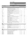
Commands Listed in Alphabetical Order
Commands Listed According to Functions
Chapter 1
Using the Program Library ............................................................................................................................... 1-1
Chapter 2
Grouping of Program Libraries ....................................................................................................................... 2-1
Chapter 3
Conventional Language ..................................................................................................................................... 3-1
Chapter 4
Palletizing ............................................................................................................................................................ 4-1
Chapter 5
Tool Operation ................................................................................................................................................... 5-1
Chapter 6
Input/Output ....................................................................................................................................................... 6-1
Chapter 7
Arm Movement ................................................................................................................................................... 7-1
Chapter 8
8.1
8.2
8.3
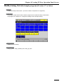
Creating TP Easy Operation Panel Screen ...................................................................................................... 8-1
How to Use Sample Programs for Creating Operation Panel Screen .................................................................. 8-1
Creating TP Easy Operation Panel Screen ........................................................................................................... 8-1
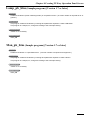
Libraries for Creating Operation Panel Screen .................................................................................................... 8-9
Chapter 9
Vision ................................................................................................................................................................... 9-1
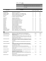
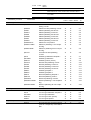
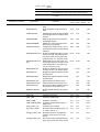
Commands Listed in Alphabetical Order
4-axis
6-axis
Vision
device
~
~
~
Available with all series of robots and vision device.
{
{
{
Available with all series of robots. The command specifications
differ between the 4-axis, 6-axis robot, and vision device.
~
V1.2
Commands
Available with the 4-axis robots and the 6-axis robots of Version
1.2 or later.
Functions
Vision
4-axis 6-axis device
Refer
to:
A
ArchMove
Executes an arch motion.
V1.9
arrange_button_pos
Specify the button arrangement (position, size, and so on) on
the screen.
V1.7
V1.7
8-12
7-49
arrange_button_size
Specifies the button arrangement (position, size, and so on)
on the screen.
V1.7
V1.7
8-12
aspACLD
Changes the internal load condition values. There are the
mass of payload, noted in grams (g), and the payload center
of gravity, noted in millimeters (mm), for the load condition
values. Designate both of them. (See Note1.)
~
~
3-1
aspChange
Selects the internal mode for proper control setting of motion
optimization.
~
~
3-3
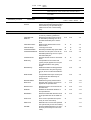
C
ClearCollisionForce
Clear the maximum external force.
V2.7
7-64
ClearSrvMonitor
Initializes the pointer of data obtained by the single-joint servo data monitor function.
V1.5
V1.5
7-54
dioConstantDistanceIoOut
Inverse the output signal on the specified I/O port each time
the associated axis is driven by the specified angle (distance
for Z axis or direct-acting axis).
V3.0
V3.0
6-2
dioSync
Synchronizes with an external device (such as a sequencer)
connected to DIO.
~
~
6-1
V2.7
7-63
D
G
GetCollisionForce
Get the maximum external force.
M
make_LABEL
Creates a title (label).
V1.7
V1.7
8-10
make_LED
Creates an LED button.
V1.7
V1.7
8-9
make_PARAM_BOX
Creates a variable button (entry & display box).
V1.7
V1.7
8-10
make_PB
Creates a PB button.
V1.7
V1.7
8-9
MotionComp
Judges whether execution of running motion commands is
complete.
V1.5
V1.5
7-48
MotionSkip
Aborts running motion commands.
V1.5
V1.5
7-47
mvResetPulseWidth
Restores default encoder pulse counts for positioning allowance.
~
~
7-1
mvResetPulseWidthJnt
Resets the encoder pulse count for an allowable positioning
error for a specified extended-joint to the default.
V1.5
V1.5
7-2
mvResetTimeOut
Restores the default motion finish timeout value.
~
~
7-3
mvReverseFlip
4-axis figure reverse
~
~
7-3
mvSetPulseWidth
Sets the permissible stop pulse width.
~
~
7-4
mvSetPulseWidthJnt
Sets the encoder pulse count for an allowable positioning error for a specified extended-joint.
V1.5
V1.5
7-5
mvSetTimeOut
Sets the timeout value for movement finish.
~
~
7-6
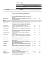
4-axis
6-axis
Vision
device
~
~
~
Available with all series of robots and vision device.
{
{
{
Available with all series of robots. The command specifications
differ between the 4-axis, 6-axis robot, and vision device.
~
V1.2
Commands
Available with the 4-axis robots and the 6-axis robots of Version
1.2 or later.
Functions
Vision
4-axis 6-axis device
Refer
to:
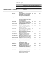
N
ndApra
Performs absolute operation with the tool coordinate system
specified (exclusively for four-axis robots).
~
3-15
ndDepa
Performs absolute operation with the tool coordinate system
specified (exclusively for four-axis robots).
~
3-16
ndInb
Converts the input of a designated port to a decimal number
and treats it as a binary number.
~
~
3-4
ndJf
A conditional branch upon receipt of OK/NG from an external
device (RS232C input/output).
~
~
3-5
ndOnb
Converts a decimal number to a binary number and outputs
it from a designated port.
~
~
3-6
ndOnbI
Converts a decimal number to a binary and outputs it from a
designated port.
~
~
3-7
ndTc
Set hte TC time.
~
V1.2
3-17
ndTs
Set the TS time and slow speed.
~
V1.2
3-17
ndVcom
Communication with an external device (kernel) (RS232C input/output)
~
~
3-14
ndVdt
Memorizes a variable transferred from an external device
(RS232C input/output).
~
~
3-8
ndVis
Transfers a designated 2-digit integer to an external device
(RS232C input/output).
~
~
3-9
ndVput
Transfers the position posture to an external device
(RS232C input/output).
~
~
3-10
ndVrst
Initializes an external device (RS232C input/output).
~
~
3-11
ndVset
Receives data from an external device (RS232C input/output).
~
~
3-12
ndVType
Designates the protocol for communication with an external
device (RS232C output).
~
~
3-13
OffPWM
Releases PWM switching on the specified axis (exclusively
for a four-axis robot).
~
7-19
OffSrvLock
Releases servo lock for the specified axis. (Exclusively for
four-axis robots)
~
7-17
OnPWM
Performs PWM switching on a specified axis (exclusively for
a four-axis robot).
~
7-18
OnSrvLock
Servo-locks a specified axis (exclusively for a four-axis robot).
~
7-16
pltDecCnt
Decreases the count of the total palletizing counter.
~
~
4-1
pltGetCnt
Obtains the total palletizing counter.
~
~
4-1
pltGetK
Obtains palletizing set value K.
~
~
4-2
pltGetK1
Obtains palletizing counter K1.
~
~
4-2
pltGetM
Obtains palletizing set value M.
~
~
4-3
pltGetM1
Obtains palletizing counter M1.
~
~
4-3
pltGetN
Obtains palletizing set value N.
~
~
4-4
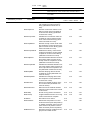
O
P
4-axis
6-axis
Vision
device
~
~
~
Available with all series of robots and vision device.
{
{
{
Available with all series of robots. The command specifications
differ between the 4-axis, 6-axis robot, and vision device.
~
V1.2
Commands
pltGetN1
Available with the 4-axis robots and the 6-axis robots of Version
1.2 or later.
Functions
Vision
4-axis 6-axis device
Refer
to:
Obtains palletizing counter N1.
~
~
4-4
pltGetNextPos
Obtains the next position.
~
~
4-5
pltGetPLT1END
Obtains a palletizing 1-row completion flag.
~
~
4-5
pltGetPLTEND
Obtains a palletizing all-row completion flag.
~
~
4-6
pltIncCnt
Increases the total palletizing counter.
~
~
4-6
pltInit1
Palletizing initialization template 1.
~
~
4-7
pltInitialize
Palletizing initialization
~
~
4-8
pltKernel
Palletizing motion (kernel)
~
~
4-9
pltLetCnt
Sets the total palletizing counter.
~
~
4-10
pltLetK1
Sets the palletizing counter K1.
~
~
4-10
pltLetM1
Sets the palletizing counter M1.
~
~
4-11
pltLetN1
Sets the palletizing counter N1.
~
~
4-11
pltMain1
Palletizing template 1
~
~
4-12
pltMain2
Palletizing template 2
~
~
4-12
pltMove
Standard palletizing template 1
~
~
4-13
pltMove0
Standard palletizing motion 1
~
~
4-14
pltResetAll
Resets all palletizing counters.
~
~
4-15
pltResetPLT1END
Resets a palletizing 1-row completion flag.
~
~
4-15
pltResetPLTEND
Resets a palletizing all-row completion flag.
~
~
4-16
R
ResetCollisionJnt
Disable the collision detection for the specified joint.
V2.7
7-62
ResetCompControl
Disables the compliance control function (dedicated command for 6-axis).
V1.4
7-29
ResetCompEralw
Initializes the allowable deviation values of the position and
the posture of the tool tip under the compliance control (dedicated command for 6-axis).
V1.4
7-42
ResetCompJLimit
Initializes the current limit under the compliance control (special compliance control function library) (dedicated command
for 6-axis).
V1.4
7-38
ResetCompRate
Initializes the compliance rates (dedicated command for 6axis).
V1.4
7-34
ResetCompVMode
Disables the velocity control mode under the compliance
control (special compliance control function library) (dedicated command for 6-axis).
V1.4
7-40
ResetCurLmt
Resets the motor current limit of the specified axis.
~
V1.2
7-13
Resetcycloid
Causes transition from the cycloid mode to the ordinary operation mode.
~
V1.4
7-22
ResetCycloidJnt
Cancels the cycloid mode set for a specified extended-joint
and restores the normal mode.
V1.5
V1.5
7-23
ResetDampRate
Initializes the damping rates under the compliance control
(dedicated command for 6-axis).
V1.4
7-44
ResetEralw
Resets the allowable deviation value of the specified axis to
the initial value.
V1.2
7-15
ResetFrcAssist
Initializes the force assistance (special compliance control
function library) (dedicated command for 6-axis).
V1.4
7-36
~
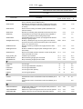
Commands
4-axis
6-axis
Vision
device
~
~
~
Available with all series of robots and vision device.
{
{
{
Available with all series of robots. The command specifications
differ between the 4-axis, 6-axis robot, and vision device.
~
V1.2
Available with the 4-axis robots and the 6-axis robots of Version
1.2 or later.
Functions
Vision
4-axis 6-axis device
Refer
to:
ResetFrcLimit
Initializes the force limiting rates (dedicated command for 6axis).
V1.4
7-32
ResetGravity
Disables the balance setting between the limited motor
torque and gravity torque, which is made with SetGravity.
V1.2
7-8
ResetGrvOffset
Disables the gravity offset function.
V1.2
7-10
ResetHighPathAccuracy
Disable the high-accuracy path control that improves the ac- V2.61 V2.61
curacy of the robot motion path in CP motion (linear, arc, and
free-curve).
7-59
ResetVibControl
Returns from the residual vibration reduction control mode to
the normal control mode.
V1.4
V1.4
7-46
set_button_param
Specifies button attributes (type, color, shape, and so on).
V1.7
V1.7
8-11
SetArchParam
Defines the start position of a horizontal movement (Arch
start position) in upward movement of the arm endpoint and
the end position in downward movement (Arch end position).
V1.9
SetCollisionJnt
Enable the collision detection for the specified joint.
V2.7
7-61
SetCollisionLevel
Specify the collision detection sensitivity level for the specified joint.
V2.7
7-65
SetCompControl
Enables the compliance function (dedicated command for 6axis).
V1.4
7-27
SetCompEralw
Sets the allowable deviation values of the position and the
posture of the tool tip under the compliance control (dedicated command for 6-axis).
V1.4
7-41
SetCompFControl
Enables the compliance control function (dedicated command for 6-axis).
V1.4
7-28
SetCompJLimit
Sets the current limit under the compliance control (special
compliance control function library) (dedicated command for
6-axis).
V1.4
7-37
SetCompRate
Sets the compliance rates under the compliance control
(dedicated command for 6-axis).
V1.4
7-33
SetCompVMode
Sets the velocity control mode under the compliance control
(special compliance control function library) (dedicated command for 6-axis).
V1.4
7-39
SetCPSpdMode
Keeps the TCP speed (Tool end speed in CP motion) constant or restores it to the default.
V1.8
V1.8
7-24
SetCurLmt
Sets the limit of motor current to be applied to the specified
axis.
{
V1.2
7-11
Setcycloid
Causes transition to the cycloid operation mode to suppress
overshoot and residual vibration at the end of PTP operation.
~
V1.4
7-20
SetCycloidJnt
Enters a specified extended-joint into the cycloid mode
where the controller suppresses the peak of overshoot and
residual oscillation that would occur in an end motion.
V1.5
V1.5
7-21
SetDampRate
Sets the damping rates under the compliance control (dedicated command for 6-axis).
V1.4
7-43
SetEralw
Modifies the allowable deviation of the specified axis.
V1.2
7-14
SetExtForceDetect
Enable/disable detection of external force.
V2.7
7-66
SetForce_HC
A current limitation library that specifies the thrust (unit: N) of
the Z coordinate with the HC robot.
S
~
~
7-50
7-26
4-axis
6-axis
Vision
device
~
~
~
Available with all series of robots and vision device.
{
{
{
Available with all series of robots. The command specifications
differ between the 4-axis, 6-axis robot, and vision device.
~
V1.2
Commands
Available with the 4-axis robots and the 6-axis robots of Version
1.2 or later.
Functions
Vision
4-axis 6-axis device
Refer
to:
SetForce_HM
A current limitation library that specifies the thrust (unit: N) of
the Z coordinate with the HM/HS robot.
7-25
SetFrcAssist
Sets the force assistance under the compliance control (special compliance control function library) (dedicated command
for 6-axis).
V1.4
7-35
SetFrcCoord
Selects a force limiting coordinate system (dedicated command for 6-axis).
V1.4
7-30
SetFrcLimit
Sets the force limiting rates (dedicated command for 6-axis).
V1.4
7-31
SetGravity
Compensates for the static load (gravity torque) applied to
each joint and attains balance with gravity torque.
V1.2
7-7
SetGrvOffset
Compensates the torque of each joint programmed with SetGravity for gravity torque.
V1.2
7-9
SetHighPathAccuracy
Enable (or disable) the high-accuracy path control that improves the accuracy of the robot motion path in CP motions
(linear, arc, and free-curve).
V2.61 V2.61
7-58
SetMonitorCond
Sets the monitoring conditions for single-joint servo data
monitor.
V1.5
V1.5
7-51
SetSingularAvoid
Enable or disable the singular point avoiding function. (for 6axis robots)
V2.61
7-60
SetVibControl
Sets to the residual vibration reduction control mode (dedicated command for 6-axis).
V1.4
7-45
~
V1.4
single_button_set
Creates only one button.
V1.7
V1.7
8-11
StartSrvMonitor
Starts monitoring single-joint servo data.
V1.5
V1.5
7-52
StopSrvMonitor
Stops monitoring single-joint servo data.
V1.5
V1.5
7-53
T
tolChange
Tool change
~
~
5-1
tolInit1
Tool change initialization template 1
~
~
5-2
tolInitialize
Tool change initialization
~
~
5-2
tolKernel
Tool change motion (kernel)
~
~
5-3
tolMain1
Tool change template 1
~
~
5-3
viTran6
Transforms the vision coordinates to robot coordinates (for 6
axes).
~
~
viTran6S
Transforms the vision coordinates to robot coordinates (for 6
axes).
V
~
9-1
9-2
X
xdSPLClrTakeArm
Changes the validity of free curve viapoint clear process execution during TakeArm.
V2.3
V2.3
7-57
xdSPLPASSNUM
Obtains the viapoint through which the free line has passed.
V2.3
V2.3
7-56
xdWAITSPLINE
Waits for the free curve to pass the designated viapoint.
V2.3
V2.3
7-55
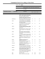
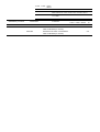
Commands Listed According to Functions
Classified by functions
4-axis
6-axis
Vision
device
~
~
~
Available with all series of robots and vision device.
{
{
{
Available with all series of robots. The command specifications
differ between the 4-axis, 6-axis robot, and vision device.
~
V1.2
Commands
Available with the 4-axis robots and the 6-axis robots of Version
1.2 or later.
Functions
Vision Refer
4-axis 6-axis device
to:
Conventional Language
aspACLD
Changes the internal load condition
values. There are the mass of payload, noted in grams (g), and the payload center of gravity, noted in
millimeters (mm), for the load condition values. Designate both of them.
~
~
3-1
aspChange
Selects the internal mode for proper
control setting of motion optimization.
~
~
3-3
ndInb
Converts the input of a designated
port to a decimal number and treats it
as a binary number.
~
~
3-4
ndJf
A conditional branch upon receipt of
OK/NG from an external device
(RS232C input/output).
~
~
3-5
ndOnb
Converts a decimal number to a binary number and outputs it from a designated port.
~
~
3-6
ndOnbI
Converts a decimal number to a binary and outputs it from a designated
port.
~
~
3-7
ndVdt
Memorizes a variable transferred
from an external device (RS232C input/output).
~
~
3-8
ndVis
Transfers a designated 2-digit integer
to an external device (RS232C input/
output).
~
~
3-9
ndVput
Transfers the position posture to an
external device (RS232C input/output).
~
~
3-10
ndVrst
Initializes an external device
(RS232C input/output).
~
~
3-11
ndVset
Receives data from an external device (RS232C input/output).
~
~
3-12
ndVType
Designates the protocol for communication with an external device
(RS232C output).
~
~
3-13
ndVcom
Communication with an external device (kernel) (RS232C input/output)
~
~
3-14
ndApra
Performs absolute operation with the
tool coordinate system specified (exclusively for four-axis robots).
~
3-15
ndDepa
Performs absolute operation with the
tool coordinate system specified (exclusively for four-axis robots).
~
3-16
ndTc
Set hte TC time.
~
V1.2
3-17
ndTs
Set the TS time and slow speed.
~
V1.2
3-17
Classified by functions
4-axis
6-axis
Vision
device
~
~
~
Available with all series of robots and vision device.
{
{
{
Available with all series of robots. The command specifications
differ between the 4-axis, 6-axis robot, and vision device.
~
V1.2
Commands
Available with the 4-axis robots and the 6-axis robots of Version
1.2 or later.
Functions
Vision Refer
4-axis 6-axis device
to:
Palletizing
pltDecCnt
Decreases the count of the total palletizing counter.
~
~
4-1
pltGetCnt
Obtains the total palletizing counter.
~
~
4-1
pltGetK
Obtains palletizing set value K.
~
~
4-2
pltGetK1
Obtains palletizing counter K1.
~
~
4-2
pltGetM
Obtains palletizing set value M.
~
~
4-3
pltGetM1
Obtains palletizing counter M1.
~
~
4-3
pltGetN
Obtains palletizing set value N.
~
~
4-4
pltGetN1
Obtains palletizing counter N1.
~
~
4-4
pltGetNextPos
Obtains the next position.
~
~
4-5
pltGetPLT1END
Obtains a palletizing 1-row completion flag.
~
~
4-5
pltGetPLTEND
Obtains a palletizing all-row completion flag.
~
~
4-6
pltIncCnt
Increases the total palletizing
counter.
~
~
4-6
pltInit1
Palletizing initialization template 1.
~
~
4-7
pltInitialize
Palletizing initialization
~
~
4-8
pltKernel
Palletizing motion (kernel)
~
~
4-9
pltLetCnt
Sets the total palletizing counter.
~
~
4-10
pltLetK1
Sets the palletizing counter K1.
~
~
4-10
pltLetM1
Sets the palletizing counter M1.
~
~
4-11
pltLetN1
Sets the palletizing counter N1.
~
~
4-11
pltMain1
Palletizing template 1
~
~
4-12
pltMain2
Palletizing template 2
~
~
4-12
pltMove
Standard palletizing template 1
~
~
4-13
pltMove0
Standard palletizing motion 1
~
~
4-14
pltResetAll
Resets all palletizing counters.
~
~
4-15
pltResetPLT1END
Resets a palletizing 1-row completion
flag.
~
~
4-15
pltResetPLTEND
Resets a palletizing all-row completion flag.
~
~
4-16
tolChange
Tool change
~
~
5-1
Tool Operation
tolInit1
Tool change initialization template 1
~
~
5-2
tolInitialize
Tool change initialization
~
~
5-2
tolKernel
Tool change motion (kernel)
~
~
5-3
tolMain1
Tool change template 1
~
~
5-3
dioSync
Synchronizes with an external device
(such as a sequencer) connected to
DIO.
~
~
6-1
Input/Output
Classified by functions
4-axis
6-axis
Vision
device
~
~
~
Available with all series of robots and vision device.
{
{
{
Available with all series of robots. The command specifications
differ between the 4-axis, 6-axis robot, and vision device.
~
V1.2
Commands
Available with the 4-axis robots and the 6-axis robots of Version
1.2 or later.
Functions
dioConstantDistanceIoOut
Inverse the output signal on the specified I/O port each time the associated
axis is driven by the specified angle
(distance for Z axis or direct-acting
axis).
mvResetPulseWidth
Restores default encoder pulse
counts for positioning allowance.
mvResetPulseWidthJnt
Resets the encoder pulse count for
an allowable positioning error for a
specified extended-joint to the default.
mvResetTimeOut
mvReverseFlip
Vision Refer
4-axis 6-axis device
to:
V3.0
V3.0
6-2
~
~
7-1
V1.5
V1.5
7-2
Restores the default motion finish
timeout value.
~
~
7-3
4-axis figure reverse
~
~
7-3
Arm Movement
mvSetPulseWidth
Sets the permissible stop pulse width.
~
~
7-4
mvSetPulseWidthJnt
Sets the encoder pulse count for an
allowable positioning error for a specified extended-joint.
V1.5
V1.5
7-5
mvSetTimeOut
Sets the timeout value for movement
finish.
~
~
7-6
SetGravity
Compensates for the static load
(gravity torque) applied to each joint
and attains balance with gravity
torque.
V1.2
7-7
ResetGravity
Disables the balance setting between
the limited motor torque and gravity
torque, which is made with SetGravity.
V1.2
7-8
SetGrvOffset
Compensates the torque of each joint
programmed with SetGravity for
gravity torque.
V1.2
7-9
ResetGrvOffset
Disables the gravity offset function.
V1.2
7-10
SetCurLmt
Sets the limit of motor current to be
applied to the specified axis.
{
V1.2
7-11
ResetCurLmt
Resets the motor current limit of the
specified axis.
~
V1.2
7-13
SetEralw
Modifies the allowable deviation of
the specified axis.
~
V1.2
7-14
ResetEralw
Resets the allowable deviation value
of the specified axis to the initial value.
~
V1.2
7-15
OnSrvLock
Servo-locks a specified axis (exclusively for a four-axis robot).
~
7-16
OffSrvLock
Releases servo lock for the specified
axis. (Exclusively for four-axis robots)
~
7-17
OnPWM
Performs PWM switching on a specified axis (exclusively for a four-axis
robot).
~
7-18
Classified by functions
4-axis
6-axis
Vision
device
~
~
~
Available with all series of robots and vision device.
{
{
{
Available with all series of robots. The command specifications
differ between the 4-axis, 6-axis robot, and vision device.
~
V1.2
Commands
Available with the 4-axis robots and the 6-axis robots of Version
1.2 or later.
Functions
Vision Refer
4-axis 6-axis device
to:
OffPWM
Releases PWM switching on the
specified axis (exclusively for a fouraxis robot).
~
7-19
Setcycloid
Causes transition to the cycloid operation mode to suppress overshoot
and residual vibration at the end of
PTP operation.
~
V1.4
7-20
SetCycloidJnt
Enters a specified extended-joint into
the cycloid mode where the controller
suppresses the peak of overshoot
and residual oscillation that would occur in an end motion.
V1.5
V1.5
7-21
Resetcycloid
Causes transition from the cycloid
mode to the ordinary operation mode.
~
V1.4
7-22
ResetCycloidJnt
Cancels the cycloid mode set for a
specified extended-joint and restores
the normal mode.
V1.5
V1.5
7-23
SetCPSpdMode
Keeps the TCP speed (Tool end
speed in CP motion) constant or restores it to the default.
V1.8
V1.8
7-24
SetForce_HM
A current limitation library that specifies the thrust (unit: N) of the Z coordinate with the HM/HS robot.
~
7-25
SetForce_HC
A current limitation library that specifies the thrust (unit: N) of the Z coordinate with the HC robot.
~
7-26
SetCompControl
Enables the compliance function
(dedicated command for 6-axis).
V1.4
7-27
SetCompFControl
Enables the compliance control function (dedicated command for 6-axis).
V1.4
7-28
ResetCompControl
Disables the compliance control function (dedicated command for 6-axis).
V1.4
7-29
SetFrcCoord
Selects a force limiting coordinate
system (dedicated command for 6axis).
V1.4
7-30
SetFrcLimit
Sets the force limiting rates (dedicated command for 6-axis).
V1.4
7-31
ResetFrcLimit
Initializes the force limiting rates
(dedicated command for 6-axis).
V1.4
7-32
SetCompRate
Sets the compliance rates under the
compliance control (dedicated command for 6-axis).
V1.4
7-33
ResetCompRate
Initializes the compliance rates (dedicated command for 6-axis).
V1.4
7-34
SetFrcAssist
Sets the force assistance under the
compliance control (special compliance control function library) (dedicated command for 6-axis).
V1.4
7-35
Classified by functions
4-axis
6-axis
Vision
device
~
~
~
Available with all series of robots and vision device.
{
{
{
Available with all series of robots. The command specifications
differ between the 4-axis, 6-axis robot, and vision device.
~
V1.2
Commands
Available with the 4-axis robots and the 6-axis robots of Version
1.2 or later.
Functions
Vision Refer
4-axis 6-axis device
to:
ResetFrcAssist
Initializes the force assistance (special compliance control function library) (dedicated command for 6axis).
V1.4
7-36
SetCompJLimit
Sets the current limit under the compliance control (special compliance
control function library) (dedicated
command for 6-axis).
V1.4
7-37
ResetCompJLimit
Initializes the current limit under the
compliance control (special compliance control function library) (dedicated command for 6-axis).
V1.4
7-38
SetCompVMode
Sets the velocity control mode under
the compliance control (special compliance control function library) (dedicated command for 6-axis).
V1.4
7-39
ResetCompVMode
Disables the velocity control mode
under the compliance control (special
compliance control function library)
(dedicated command for 6-axis).
V1.4
7-40
SetCompEralw
Sets the allowable deviation values of
the position and the posture of the
tool tip under the compliance control
(dedicated command for 6-axis).
V1.4
7-41
ResetCompEralw
Initializes the allowable deviation values of the position and the posture of
the tool tip under the compliance control (dedicated command for 6-axis).
V1.4
7-42
SetDampRate
Sets the damping rates under the
compliance control (dedicated command for 6-axis).
V1.4
7-43
ResetDampRate
Initializes the damping rates under
the compliance control (dedicated
command for 6-axis).
V1.4
7-44
SetVibControl
Sets to the residual vibration reduction control mode (dedicated command for 6-axis).
V1.4
V1.4
7-45
ResetVibControl
Returns from the residual vibration
reduction control mode to the normal
control mode.
V1.4
V1.4
7-46
MotionSkip
Aborts running motion commands.
V1.5
V1.5
7-47
MotionComp
Judges whether execution of running
motion commands is complete.
V1.5
V1.5
7-48
ArchMove
Executes an arch motion.
V1.9
7-49
SetArchParam
Defines the start position of a horizontal movement (Arch start position)
in upward movement of the arm endpoint and the end position in downward movement (Arch end position).
V1.9
7-50
SetMonitorCond
Sets the monitoring conditions for single-joint servo data monitor.
V1.5
V1.5
7-51
Classified by functions
4-axis
6-axis
Vision
device
~
~
~
Available with all series of robots and vision device.
{
{
{
Available with all series of robots. The command specifications
differ between the 4-axis, 6-axis robot, and vision device.
~
V1.2
Commands
Available with the 4-axis robots and the 6-axis robots of Version
1.2 or later.
Functions
Vision Refer
4-axis 6-axis device
to:
StartSrvMonitor
Starts monitoring single-joint servo
data.
V1.5
V1.5
7-52
StopSrvMonitor
Stops monitoring single-joint servo
data.
V1.5
V1.5
7-53
ClearSrvMonitor
Initializes the pointer of data obtained
by the single-joint servo data monitor
function.
V1.5
V1.5
7-54
xdWAITSPLINE
Waits for the free curve to pass the
designated viapoint.
V2.3
V2.3
7-55
xdSPLPASSNUM
Obtains the viapoint through which
the free line has passed.
V2.3
V2.3
7-56
xdSPLClrTakeArm
Changes the validity of free curve viapoint clear process execution during
TakeArm.
V2.3
V2.3
7-57
SetHighPathAccuracy Enable (or disable) the high-accuracy
path control that improves the accuracy of the robot motion path in CP
motions (linear, arc, and free-curve).
V2.61 V2.61
7-58
ResetHighPathAccuracy
Disable the high-accuracy path control that improves the accuracy of the
robot motion path in CP motion (linear, arc, and free-curve).
V2.61 V2.61
7-59
SetSingularAvoid
Enable or disable the singular point
avoiding function. (for 6-axis robots)
V2.61
7-60
SetCollisionJnt
Enable the collision detection for the
specified joint.
V2.7
7-61
ResetCollisionJnt
Disable the collision detection for the
specified joint.
V2.7
7-62
GetCollisionForce
Get the maximum external force.
V2.7
7-63
ClearCollisionForce
Clear the maximum external force.
V2.7
7-64
SetCollisionLevel
Specify the collision detection sensitivity level for the specified joint.
V2.7
7-65
SetExtForceDetect
Enable/disable detection of external
force.
V2.7
7-66
Libraries for Creating Operation Panel Screen
make_PB
make_LED
make_LABEL
make_PARAM_BOX
Creates a PB button.
V1.7
V1.7
8-9
Creates an LED button.
V1.7
V1.7
8-9
Creates a title (label).
V1.7
V1.7
8-10
Creates a variable button (entry &
display box).
V1.7
V1.7
8-10
single_button_set
Creates only one button.
V1.7
V1.7
8-11
set_button_param
Specifies button attributes (type, color, shape, and so on).
V1.7
V1.7
8-11
arrange_button_size
Specifies the button arrangement
(position, size, and so on) on the
screen.
V1.7
V1.7
8-12
arrange_button_pos
Specify the button arrangement (position, size, and so on) on the screen.
V1.7
V1.7
8-12
Classified by functions
4-axis
6-axis
Vision
device
~
~
~
Available with all series of robots and vision device.
{
{
{
Available with all series of robots. The command specifications
differ between the 4-axis, 6-axis robot, and vision device.
~
V1.2
Commands
Available with the 4-axis robots and the 6-axis robots of Version
1.2 or later.
Functions
Vision Refer
4-axis 6-axis device
to:
Vision
viTran6
Transforms the vision coordinates to
robot coordinates (for 6 axes).
viTran6S
Transforms the vision coordinates to
robot coordinates (for 6 axes).
~
~
~
9-1
9-2
Chapter 1 Using the Program Library
Chapter 1
Using the Program Library
To use program libraries, you must run a program bank in WINCAPSIII and add necessary libraries to the program bank. For the procedures of the program bank, refer to the WINCAPSIII Guide.
1-1
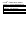
Chapter 2 Grouping of Program Libraries
Chapter 2
Grouping of Program Libraries
Program libraries provided as standard are grouped as listed below in the WINCAPSIII program bank.
Library name
Contents
!DW00 : Conventional language Functions equivalent to commands provided in the conventional language
2-1
!DW01 : Palletizing
Palletizing functions
!DW02 : Tool operation
Tool operation related functions
!DW03 : Input, Output
DIO and RS-232C I/O related functions
!DW04 : Arm Compliance
Arm motion related compliance functions
!DW05 : Arm Conveyer
Arm motion related conveyor tracking functions
!DW06 : Arm Collision
Arm motion related collision detection functions
!DW07 : Arm Spline
Arm motion related free curve functions
!DW08 : Arm Set/Reset
Enable/disable programs of other arm motion related functions
!DW09 : Arm Misc.
Other arm motion related functions
!DW10 : Vision
Vision operation related functions
!DW11 : Miscellaneous
Compatibility with earlier versions of the controller software
Chapter 3 Conventional Language
Chapter 3
Conventional Language
Provides similar functions to those of the conventional language which were used in the RC3 controller model.
aspACLD (Library)
Function
Changes the internal load condition values. There are the mass of payload, noted in grams (g), and the payload center of gravity, noted in millimeters (mm), for the load condition values. Designate both of them. (See
Note1.)
Syntax
aspACLD (<Mass of payload>, <Payload center of gravity coordinate X >, <Payload center of gravity coordinate Y>, <Payload center of gravity coordinate Z>)
Note1: For 4-axes robot in Ver.1.9 or later, <Payload center of gravity coordinate Z> is replaced with <Inertia
of payload (kgcm2)>
Description
The mass of payload is the mass of load (end-effector and workpiece) mounted on the 6th axis of the robot.
This unit is designated as (g).
For the load center of gravity position, designate the payload center of gravity using the TOOL0 coordinates.
The unit is millimeters (mm). (See Note1.)
The reference position of the TOOL0 coordinates is in the center of the 6th axis flange. For component Y, the
direction is from the flange center to the pinhole of "φU6H7 (orientation vector direction). For component Z, the
direction is vertical to the flange surface through the flange center (approach vector direction). For component
X, the direction of the X axis (normal vector direction) is the right-hand coordinate system, when the orientation
vector is set to the Y axis and the approach vector is set to the Z axis. Refer to the PROGRAMMER'S MANUAL
I, "4.7 Control Set of Motion Optimization in User Preferences."
Even if you change only one of the four values of the mass of payload, the payload center of gravity X, the
payload center of gravity Y, and payload center of gravity Z ,describe all of the 4 values again.
It takes about 0.1 sec. to switch the load condition values. Frequently switching the load condition may cause
operational delays. Do not change the mode during pass motion while near an obstacle because the path locus
may shift. This may delay switching if you change the load condition values.
Macro Definition
Requires file <pacman.h>
Related Terms
Refer to the PROGRAMMER'S MANUAL I, " 4.7 Control Set of Motion Optimization in User Preferences."
3-1
Chapter 3 Conventional Language
Notes
• For the mass of payload, designate it with a numerical value of the specified range for each robot type. If
you designate a value out of this range, the error message "60d2. The payload setting value exceeds the
permissible value" will be displayed.
• For the payload center of gravity, enter it so that it satisfies the specified range for each robot type. If it is
out of this range, the error message "60d2. The payload setting value exceeds the permissible value" will
be displayed.
• When setting the internal payload condition, observe the following rule relative to the external payload condition. If not, the error message "60d2 The payload setting value exceeds the permissible value" will be
displayed.
0.5 x External payload condition ≤ Internal payload condition ≤ External payload condition
Example
CALL aspACLD(8500,-50,100,80) 'Sets the internal payload conditions.
'Mass of payload:8500(g), Payload center of gravity
'component X: -50(mm), component Y: 100(mm),
'component Z: 80(mm)
3-2
Chapter 3 Conventional Language
aspChange (Library)
Function
Selects the internal mode for proper control setting of motion optimization.
Syntax
aspChange (<Mode>)
Description
This statement switches the mode for control setting of motion optimization.
<Setting value>
0 → Invalid
1 → Valid only for PTP
2 → Valid only for CP
3 → Valid for both PTP and CP.
It takes about 0.1 sec. to switch the load condition values. Frequently switching the load condition may cause
operational delays. Do not change the mode during pass motion, near an obstacle because the path locus
may shift. This may delay switching if you change the load condition values.
Macro Definition
Requires file <pacman.h>
Related Terms
Refer to the PROGRAMMER'S MANUAL I, " 4.7 Control Set of Motion Optimization in User Preferences."
Notes
For <Mode>, designate it with a numerical value between 0 and 3. If it is out of this range, the error message
"6003 Beyond the valid value range" will be displayed.
Example
CALL aspChange(1)
'Sets the internal mode in the control sets of motion
'optimization to 1.
3-3
Chapter 3 Conventional Language
ndInb (Library)
Function
Converts the input of a designated port to a decimal number and treats it as a binary number.
Syntax
ndlnb (<Integer variable number>, <Least significant digit output port number>, <Most significant digit output
port number>)
Description
This statement provides a similar function to an INB instruction in the conventional language.
The system reads the status of a designated input port signal and converts it to a decimal number by treating
it as a binary number.
The system assigns a converted value to the integer variable.
Related Terms
ndOnb, ndOnbI
Remarks
You can define the same function with DEFIO and IN instruction in the PAC language. Use DEFIO and IN
instructions because this method is more effective.
For input ports, use 16 ports or less in series. If you designate more than 16 ports, no processing will be done.
Example
CALL ndInb(1,552,567)
3-4
'Reads the status of input ports 552 to 567 as a 16-bit
'binary, converts it to decimal, and assigns it
'to the integer variable (1).
Chapter 3 Conventional Language
ndJf (Library)
Function
A conditional branch upon receipt of OK/NG from an external device (RS232C input/output).
Syntax
ndJf (<2-digit integer>, <Determination argument>)
Description
This statement provides a similar function to a JF instruction in the conventional language.
The system transfers a 2-digit integer to an external device and calculates a response result to execute a conditional branch in the program.
If the response from the external device is OK, the system proceeds to the next step. If it is not good, it branches to a labeled step.
Related Terms
ndVcom, ndVType
Example
#include <Pacman.h>
PROGRAM PRO1
DEFINT JF_VAL = 0
FLUSH
CALL ndVType(1)
CALL ndVrst
CALL ndVset(0)
CALL ndVis(3)
CALL ndJf(3,JF_VAL)
IF JF_VAL = TRUE THEN
CALL ndVset(3)
CALL ndVdt(pacPOS,1)
CALL ndVdt(pacJNT,1)
CALL ndVdt(pacTRN,1)
'Sets the protocol (Conventional = 0/ New = 1).
'Initializes the external device.
'Clears the received data (VDT) to 0.
'Starts up the external device (Sends 03).
'Obtains a response result from the external device
'(Sends 03).
'Receives data, if the response is OK (TRUE).
'Receives 10 data from the external device (Sends 03).
'Assigns the data received from the external device
'to variable (P1).
'Assigns the data received from the external device
'to variable (J1).
'Assigns the data received from the external device
'to variable (T1).
END IF
END
3-5
Chapter 3 Conventional Language
ndOnb (Library)
Function
Converts a decimal number to a binary number and outputs it from a designated port.
Syntax
ndOnb (<Integer value>, <Least significant digit output port number>, <Most significant digit output port number>)
Description
This statement provides a similar function to an ONB instruction in the conventional language.
The system converts an integer to a binary number and outputs it from a designated port.
Use the ndOnbI Library for the ONB instruction to format type I variable value output.
Related Terms
ndInb, ndOnbI
Remarks
For output ports, use 16 ports or less in series. When you designate more than 16 ports, if low order port >
high order port, or if you designate a port not available for output, no processing will be done.
Example
CALL ndOnb(15,769,784)
3-6
'Converts a decimal 15 to a 16-bit binary and
'outputs it to output ports 769 to 784.
Chapter 3 Conventional Language
ndOnbI (Library)
Function
Converts a decimal number to a binary and outputs it from a designated port.
Syntax
ndOnbI (<Integer variable number>,<Least significant digit output port number>, <Most significant digit output
port number>)
Description
This statement provides a similar function to an ONB instruction in the conventional language.
The system converts an integer to a binary number and outputs it from a designated port.
Use the ndOnb Library for the ONB instruction to format type I variable value output.
Related Terms
ndInb, ndOnb
Remarks
For output ports, use 16 ports or less in series. When you designate more than 16 ports, if low order port >
high order port or if you designate a port not available for output, no processing will be done.
Example
CALL ndOnbI(1,769,784)
'Converts the value of integer variable I (number 1)
'to a 16-bit binary and outputs it to output ports
'769 to 784.
3-7
Chapter 3 Conventional Language
ndVdt (Library)
Function
Memorizes a variable transferred from an external device (RS232C input/output).
Syntax
ndVdt (<Storage variable type>, <Storage variable number>)
Description
This statement provides a similar function of a VDT instruction in the conventional language.
The system assigns the data transferred from an external device to a storage variable number, in a designated
storage variable type format (P/J/T).
Macro Definition
Requires file <pacman.h>
Related Terms
ndVcom, ndVset
Example
#include <Pacman.h>
PROGRAM PRO1
DEFINT JF_VAL = 0
FLUSH
CALL ndVType(1)
CALL ndVrst
CALL ndVset(0)
CALL ndVis(3)
CALL ndJf(3,JF_VAL)
IF JF_VAL = TRUE THEN
CALL ndVset(3)
CALL ndVdt(pacPOS,1)
CALL ndVdt(pacJNT,1)
CALL ndVdt(pacTRN,1)
END IF
END
3-8
'Sets the protocol (Conventional = 0/ New = 1).
'Initializes the external device.
'Clears the received data (VDT) to 0.
'Starts up the external device (Sends 03).
'Obtains a response result from the external device
'(Sends 03).
'Receives data, if the response is OK (TRUE).
'Receives 10 data from the external device (Sends 03).
'Assigns the data received from the external device
'to variable (P1).
'Assigns the data received from the external device
'to variable (J1).
'Assigns the data received from the external device
'to variable (T1).
Chapter 3 Conventional Language
ndVis (Library)
Function
Transfers a designated 2-digit integer to an external device (RS232C input/output).
Syntax
ndVis (<2 digit integer>)
Description
This statement provides a similar function to a VIS instruction in the conventional language.
The robot transfers a designated 2-digit integer to an external device after checking the preparation status of
the external device.
Related Terms
ndVcom, ndVType
Example
#include <Pacman.h>
PROGRAM PRO1
DEFINT JF_VAL = 0
FLUSH
CALL ndVType(1)
CALL ndVrst
CALL ndVset(0)
CALL ndVis(3)
CALL ndJf(3,JF_VAL)
IF JF_VAL = TRUE THEN
CALL ndVset(3)
CALL ndVdt(pacPOS,1)
CALL ndVdt(pacJNT,1)
CALL ndVdt(pacTRN,1)
'Sets the protocol (Conventional = 0/ New = 1).
'Initializes the external device.
'Clears the received data (VDT) to 0.
'Starts up the external device (Sends 03).
'Obtains a response result from the external device
'(Sends 03).
'Receives data, if the response is OK (TRUE).
'Receives 10 data from the external device (Sends 03).
'Assigns the data received from the external device
'to variable (P1).
'Assigns the data received from the external device
'to variable (J1).
'Assigns the data received from the external device
'to variable (T1).
END IF
END
3-9
Chapter 3 Conventional Language
ndVput (Library)
Function
Transfers the position posture to an external device (RS232C input/output).
Syntax
ndVput (<Storage variable type>, <Storage variable number>)
Description
This statement provides a similar function to a VPUT instruction in the conventional language.
If <Position variable number> is negative:
The system transfers the robot's current position coordinates (the home position coordinates in the tool coordinate system when the tool is defined.) and a posture or contents of the position variable to an external device.
If <Position variable number> is positive:
The system transfers a storage variable type and contents of the position variable designated with a storage
variable number, to the external device.
Macro Definition
Requires file <pacman.h>
Related Terms
ndVcom, ndVType
Example
#include <pacman.h>
PROGRAM PRO65
FLUSH
CALL
ndVType(1)
'Sets the protocol (Conventional = 0/ New = 1)
CALL
nsVrst
'Initializes the external device.
CALL
ndVis(4)
'Starts up the external device (Sends 03).
P1 = (1,2,3,4,5,6,7)
J1 = (11,12,13,14,15,16)
T1 = (21,22,23,24,25,26,27,28,29,30)
CALL
ndVput(pacPOS,1) 'Sends the data of variable "P1"
CALL
ndVput(pacJNT,1) 'Sends the data of variable "J1"
CALL
ndVput(pacTRN,1) 'Sends the data of variable "T1"
END
3-10
Chapter 3 Conventional Language
ndVrst (Library)
Function
Initializes an external device (RS232C input/output).
Syntax
ndVrst
Description
This statement provides a similar function to a VRST instruction in the conventional language.
It also directs the external device to initialize.
Related Terms
ndVcom, ndVType
Example
#include <Pacman.h>
PROGRAM PRO1
DEFINT JF_VAL = 0
FLUSH
CALL ndVType(1)
CALL ndVrst
CALL ndVset(0)
CALL ndVis(3)
CALL ndJf(3,JF_VAL)
IF JF_VAL = TRUE THEN
CALL ndVset(3)
CALL ndVdt(pacPOS,1)
CALL ndVdt(pacJNT,1)
CALL ndVdt(pacTRN,1)
'Sets the protocol (Conventional = 0/ New = 1).
'Initializes the external device.
'Clears the received data (VDT) to 0.
'Starts up the external device (Sends 03).
'Obtains a response result from the external device
'(Sends 03).
'Receives data, if the response is OK (TRUE).
'Receives 10 data from the external device (Sends 03).
'Assigns the data received from the external device
'to variable (P1).
'Assigns the data received from the external device
'to variable (J1).
'Assigns the data received from the external device
'to variable (T1).
END IF
END
3-11
Chapter 3 Conventional Language
ndVset (Library)
Function
Receives data from an external device (RS232C input/output).
Syntax
ndVset (<2-digit integer>)
Description
This statement provides a similar function to a VSET instruction in the conventional language.
The system receives data from an external device and adds (assigns) it to an internal variable after the robot
sends a designated 2-digit integer to the external device. If you designate <2-digit integer> to "0", the system
initializes an internal variable with "0".
Related Terms
ndVcom, ndVType
Example
#include <Pacman.h>
PROGRAM PRO1
DEFINT JF_VAL = 0
FLUSH
CALL ndVType(1)
CALL ndVrst
CALL ndVset(0)
CALL ndVis(3)
CALL ndJf(3,JF_VAL)
IF JF_VAL = TRUE THEN
CALL ndVset(3)
CALL ndVdt(pacPOS,1)
CALL ndVdt(pacJNT,1)
CALL ndVdt(pacTRN,1)
END IF
END
3-12
'Sets the protocol (Conventional = 0/ New = 1).
'Initializes the external device.
'Clears the received data (VDT) to 0.
'Starts up the external device (Sends 03).
'Obtains a response result from the external device
'(Sends 03).
'Receives data, if the response is OK (TRUE).
'Receives 10 data from the external device (Sends 03).
'Assigns the data received from the external device
'to variable (P1).
'Assigns the data received from the external device
'to variable (J1).
'Assigns the data received from the external device
'to variable (T1).
Chapter 3 Conventional Language
ndVType (Library)
Function
Designates the protocol for communication with an external device (RS232C output).
Syntax
ndVType (<2-digit integer>)
Description
This statement designates the communication protocol for ndVis, ndJf, ndVset, ndVrst, ndVput, and ndVcom.
The initial value of each library is set in the new protocol.
(Old protocol = 0/new protocol = 1)
Related Terms
ndVis, ndJf, ndVset, ndVput, ndVcom
Example
#include <Pacman.h>
PROGRAM PRO1
DEFINT JF_VAL = 0
FLUSH
CALL ndVType(1)
CALL ndVrst
CALL ndVset(0)
CALL ndVis(3)
CALL ndJf(3,JF_VAL)
IF JF_VAL = TRUE THEN
CALL ndVset(3)
CALL ndVdt(pacPOS,1)
CALL ndVdt(pacJNT,1)
CALL ndVdt(pacTRN,1)
'Sets the protocol (Conventional = 0/ New = 1).
'Initializes the external device.
'Clears the received data (VDT) to 0.
'Starts up the external device (Sends 03).
'Obtains a response result from the external device
'(Sends 03).
'Receives data, if the response is OK (TRUE).
'Receives 10 data from the external device (Sends 03).
'Assigns the data received from the external device
'to variable (P1).
'Assigns the data received from the external device
'to variable (J1).
'Assigns the data received from the external device
'to variable (T1).
END IF
END
3-13
Chapter 3 Conventional Language
ndVcom (Library)
Function
Communication with an external device (kernel) (RS232C input/output)
Syntax
ndVcom (<Function code>, <Array variable>)
Description
This is a kernel program for communication with an external equipment and is required for using the communication libraries (ndVis, ndJf, ndVset, ndVrst, ndVput, and ndVType).
For Controller System Version 1.2* or earlier, use ndVcom contained in the version 1.2 compatible class. If in
Version 1.2* or earlier ndVcom not in the version 1.2 compatible class but in classes 1 to 6 is used, a compilation error will result.
To check the controller software version, refer to the SETTING-UP MANUAL, Chapter 5, Section 5.7, [F6 Set][F6 Maint.]-[F2 Version].
ATTENTION
This program is not automatically executed by multitasking operation.
If you execute this by multitasking operation, you need to change this for synchronization using a
semaphore etc.
Related Terms
ndVis, ndJf, ndVset, ndVrst, ndVput, ndVdt, ndVType
3-14
Chapter 3 Conventional Language
ndApra (Library)
Function
Performs absolute operation with the tool coordinate system specified (exclusively for four-axis robots).
Syntax
ndApra (<reference position> <Z coordinate> <stopping accuracy>)
Description
Provides a function similar to that of the APRA instruction in the conventional language.
Performs PTP movement by specifying the Z coordinate of the reference position only. The operation varies
with the specified stopping accuracy as follows:
0: End operation
1: Path operation
2: Checking arrival at the target position by means of the encoder value
To use a function similar to that of the APRT instruction in the conventional language, calculate the position
type value by translating deviation calculation (see 7.9.7 Position Calculation) by referring to this library and
use the MOVE instruction.
Related Terms
ndDepa
Example
PROGRAM PRO1
TAKEARM
CALL ndApra((P0),400.0,1)
MOVE P,@0 P0
CALL ndDepa(400.0,0)
GIVEARM
END
'Moves to 400 in Z coordinate at XP0.
'Moves to P0.
'Moves to 400 in Z coordinate at P0.
3-15
Chapter 3 Conventional Language
ndDepa (Library)
Function
Performs absolute operation with the tool coordinate system specified (exclusively for four-axis robots).
Syntax
ndDepa (< coordinate> <stopping accuracy>)
Description
Provides a function similar to that of the DEPA function in the conventional language.
Performs PTP movement from the current position by specifying only the Z coordinate. The operation varies
with the stopping accuracy as follows:
0: End operation
1: Path operation
2: Checking arrival at the target position by means of the encoder value
To use a function similar to that of the DRET instruction in the conventional language, calculate the position
type value by translating deviation calculation (see 7.9.7 Position Calculation) by referring to this library and
use the MOVE instruction.
Related Terms
ndApra
Example
PROGRAM PRO1
TAKEARM
CALL ndApra((P0),400.0,1)
MOVE P,@0 P0
CALL ndDepa(400.0,0)
GIVEARM
END
3-16
'Moves to 400 in Z coordinate at XP0.
'Moves to P0.
'Moves to 400 in Z coordinate at P0.
Chapter 3 Conventional Language
ndTc (Library) [Version 1.2 or later]
Function
Set hte TC time.
Syntax
ndTc (<TC time>)
Description
This statement provides the equivalent function as of the TC command.
The setting value can range from 0 sec. to 600 sec.
The factory setting is 60 sec.
Setting TC time to 0 sec. disables safty start function, which is equivalent to TC OFF command.
Macro Definition
A file <pacman.h> is required.
Related Terms
ndTs
ndTs (Library) [Version 1.2 or later]
Function
Set the TS time and slow speed.
Syntax
ndTS (<TS time>, <slow speed>)
Description
This statement provides the equivalent function as of the TS command.
The setting value for the TS time can range from 3 sec. to 30 sec.
The factory setting is 5 sec.
The setting value for the slow speed can range from 1 % to 10 %.
The factory setting is 10 %.
Macro Definition
A file <pacman.h> is required.
Related Terms
ndTc
3-17
Chapter 4 Palletizing
Chapter 4
Palletizing
Describes the libraries for palletizing functions.
pltDecCnt (Library)
Function
Decreases the count of the total palletizing counter.
Syntax
pltDecCnt (<Palletizing number>)
Description
The total palletizing counter, designated with a palletizing number, decreases by one (-1).
By editing the palletizing counter, you can palletize a hounds tooth pattern or an arbitrary step pattern.
Related Terms
pltGetCnt, pltIncCnt, pltKernel, pltLetCnt
Example
CALL pltDecCnt(1)
'Decreases total palletizing counter No. 1 by
'one (-1).
pltGetCnt (Library)
Function
Obtains the total palletizing counter.
Syntax
pltGetCnt (<Palletizing number>, <Cnt save integer variable number>)
Description
Obtains the total palletizing counter of a designated palletizing number.
Related Terms
pltDecCnt, pltIncCnt, pltKernel, pltLetCnt
Example
CALL pltGetCnt(1, 0)
CALL pltLetCnt(1, I[0] - 1)
4-1
'Assigns the current counter to I[0].
'Decreases the counter by 1.
Chapter 4 Palletizing
pltGetK (Library)
Function
Obtains palletizing set value K.
Syntax
pltGetK (<Palletizing number>, <K save integer variable number>)
Description
This statement obtains palletizing set value K of a designated palletizing number.
Related Terms
pltGetK1, pltLetK1, pltKernel
Example
CALL pltGetK(1,10)
'Assigns palletizing value K of palletizing No. 1
'to integer variable 10.
pltGetK1 (Library)
Function
Obtains palletizing counter K1.
Syntax
pltGetK1 (<Palletizing number>, <K1 save integer variable number>)
Description
This statement obtains palletizing counter K1 of a designated palletizing number.
Related Terms
pltGetK, pltLetK1, pltKernel
Example
CALL pltGetK1(1,10)
'Assigns palletizing counter K1 of palletizing
'No. 1 to integer variable 10.
4-2
Chapter 4 Palletizing
pltGetM (Library)
Function
Obtains palletizing set value M.
Syntax
pltGetM (<Palletizing number>, <M save integer variable number>)
Description
This statement obtains palletizing set value M of a designated palletizing number.
Related Terms
pltGetM1, pltLetM1, pltKernel
Example
CALL pltGetM(1,10)
'Assigns palletizing value M of palletizing No. 1
'to integer variable 10.
pltGetM1 (Library)
Function
Obtains palletizing counter M1.
Syntax
pltGetM1 (<Palletizing number>, <M1 save integer variable number>)
Description
This statement obtains palletizing counter M1 of a designated palletizing number.
Related Terms
pltGetM, pltLetM1, pltKernel
Example
CALL pltGetM1(1,10)
4-3
'Assigns palletizing counter M1 of palletizing
'No. 1 to integer variable 10.
Chapter 4 Palletizing
pltGetN (Library)
Function
Obtains palletizing set value N.
Syntax
pltGetN (<Palletizing number>, <N save integer variable number>)
Description
This statement obtains palletizing set value N of a designated palletizing number.
Related Terms
pltGetN1, pltLetN1, pltKernel
Example
CALL pltGetN(1,10)
'Assigns palletizing value N of palletizing No. 1
'to integer variable 10.
pltGetN1 (Library)
Function
Obtains palletizing counter N1.
Syntax
pltGetN1 (<Palletizing number>, <N1 save integer variable number>)
Description
Obtains palletizing counter N1 of a designated palletizing number.
Related Terms
pltGetN, pltLetN1, pltKernel
Example
CALL pltGetN1(1,10)
'Assigns palletizing counter N1 of palletizing
'No. 1 to integer variable 10.
4-4
Chapter 4 Palletizing
pltGetNextPos (Library)
Function
Obtains the next position.
Syntax
pltGetNextPos (<Palletizing number>, <Next position obtaining position type variable>)
Description
This statement obtains the next position. When this library is executed, the palletizing counter increases.
Therefore, when you obtain the next position but do not execute it, you must decrease the pltDecCnt and so on.
Related Terms
pltMove, pltKernel
Example
CALL pltGetNextPos(1,10) 'Assigns a position immediately following
'palletizing No. 1 to integer variable 10.
pltGetPLT1END (Library)
Function
Obtains a palletizing 1-row completion flag.
Syntax
pltGetPLT1END (<Palletizing number>, <1-row completion flag save integer number>)
Description
Stores a palletizing 1-row completion flag into I[<1-row completion flag save integer number>].
Related Terms
pltGetPLTEND, pltResetPLT1END, pltKernel
Example
CALL pltGetPLT1END(1,10) 'Assigns a 1-row completion flag of palletizing
'No. 1 to integer variable 10.
4-5
Chapter 4 Palletizing
pltGetPLTEND (Library)
Function
Obtains a palletizing all-row completion flag.
Syntax
pltGetPLTEND (<Palletizing number>, <All row-completion flag save integer number>)
Description
This statement stores a palletizing all row completion flag into I[<All-row completion flag save integer number>].
Related Terms
pltGetPLT1END, pltResetPLTEND, pltKernel
Example
CALL pltGetPLTEND(1,10)
'Assigns an all-row completion flag of palletizing
'No. 1 to integer variable 10.
pltIncCnt (Library)
Function
Increases the total palletizing counter.
Syntax
pltIncCnt (<Palletizing number>)
Description
This statement increases the total palletizing counter of a designated palletizing number by +1 from the current
value.
By editing the palletizing counter, you can palletize a hounds tooth pattern or arbitrary step pattern.
Related Terms
pltDecCnt, pltGetCnt, pltKernel, pltLetCnt
Example
CALL pltIncCnt(1)
'Increases the total palletizing counter of
'palletizing No. 1 by one (+1).
4-6
Chapter 4 Palletizing
pltInit1 (Library)
Function
Palletizing initialization template 1.
Syntax
pltInit1
Description
This is an example of pltInitialize.
For the meanings of arguments, refer to the arguments used with the pltInitialize commands.
Related Terms
pltInitialize
4-7
Chapter 4 Palletizing
pltInitialize (Library)
Function
Palletizing initialization
Syntax
pltInitialize (<Palletizing number>, <Lateral partition number>, <Longitudinal partition number>, <Pile number>, <Approach length>, <Depart length>, <Pallet height>, <Pallet 4-corner type 1P variable number>, <Pallet
4-corner type 2P variable number>, <Pallet 4-corner type 3P variable number>, <Pallet 4-corner type 4P variable number>)
Description
This statement is an initialization program for defining palletizing motion.
It is more effective to use this program rather than the pltResetAll Library, if you initialize only the palletizing
counter.
ATTENTION
Without execution of pltInitialize, no palletizing motion will be executed.
Macro Definition
mcApprVal
: F type variable number to assign the approach length.
McDepVal
: F type variable number to assign the depart length.
McPltH
: A type F variable number to assign the pallet height.
ATTENTION
If these definitions compete with the user's variable number, define the macro again.
Related Terms
pltKernel
Example
CALL pltInitialize(0,4,3,1,50,50,50,52,53,54,55)
'Initializes palletizing parameters; Palletizing number:0,
'Lateral partition number:4, Longitudinal partition number:3
'Pile number:1, Approach length:50 mm, Depart length:50 mm,
'Pallet height:50 mm, Pallet 4-corner type 1P:52, 2P:53,
'3P:54, 4P:55.
4-8
Chapter 4 Palletizing
pltKernel (Library)
Function
Palletizing motion (kernel)
Syntax
pltKernel (<Palletizing number>, <Action number>, <Action argument>, <Error number>)
Description
This statement is a kernel program for palletizing motion. This library is required to use all other palletizing
libraries.
ATTENTION
This program is not automatically executed by multitasking operation. If you execute this by multitasking, you need to change this for synchronization using a semaphore.
Macro Definition
mcPaltMax: Maximum pallet number
You can easily increase pallets in number by defining this macro again.
ATTENTION
If you increase the number of pallets, the system consumes the local variable area.
Related Terms
pltInitialize
Remarks
• Only other libraries call this library. The user does not directly call this.
• For directly using this, you should fully understand the contents of the program.
4-9
Chapter 4 Palletizing
pltLetCnt (Library)
Function
Sets the total palletizing counter.
Syntax
pltLetCnt (<Palletizing number>, <All counter setting values>)
Description
This statement can set the total palletizing counter of a designated palletizing number.
By editing the palletizing counter, you can palletize a hounds tooth pattern or arbitrary step pattern.
Related Terms
pltDecCnt, pltGetCnt, pltIncCnt, pltKernel
Example
CALL pltLetCnt(1,12)
'Sets the total palletizing counter of palletizing
'No. 1 to 12.
pltLetK1 (Library)
Function
Sets the palletizing counter K1.
Syntax
pltLetK1 (<Palletizing number>, <K1 setting value>)
Description
This statement can set the counter K1 of a designated palletizing number.
By editing the palletizing counter, you can palletize a hounds tooth pattern or arbitrary step pattern.
Related Terms
pltGetK1, pltKernel
Example
CALL pltLetK1(1,1)
'Sets palletizing counter K1 of palletizing No. 1 to 1.
4-10
Chapter 4 Palletizing
pltLetM1 (Library)
Function
Sets the palletizing counter M1.
Syntax
pltLetM1 (<Palletizing number>, <M1 setting value>)
Description
This statement can set the counter M1 of a designated palletizing number.
By editing the palletizing counter, you can palletize a hounds tooth pattern or arbitrary step pattern.
Related Terms
pltGetM1, pltKernel
Example
CALL pltLetM1(1,4)
'Sets palletizing counter M1 of palletizing No. 1 to 4.
pltLetN1 (Library)
Function
Sets the palletizing counter N1.
Syntax
pltLetN1 (<Palletizing number>, <N1 setting value>)
Description
This statement can set the counter N1 of a designated palletizing number.
By editing the palletizing counter, you can palletize a hounds tooth pattern or arbitrary step pattern.
Related Terms
pltGetN1, pltKernel
Example
CALL pltLetN1(1,3)
4-11
'Sets palletizing counter N1 of palletizing
'No. 1 to 3.
Chapter 4 Palletizing
pltMain1 (Library)
Function
Palletizing template 1
Syntax
pltMain1
Description
This statement is the basic work statement to pick up a part and move it to the assembling position.
Macro Definition
pltIndex palletizing number
Related Terms
pltMain2
Remarks
You may modify the template to meet your needs.
pltMain2 (Library)
Function
Palletizing template 2
Syntax
pltMain2
Description
This statement is the basic work statement to pick up a part and move it to the assembling position. Before
picking up a part, the robot checks that the previous pick-up was correctly done.
Macro Definition
pltIndex
: palletizing number
ChuckNG
: pick-up NG signal (DIO number)
Related Terms
pltMain1
Remarks
You may modify the template to meet your needs.
4-12
Chapter 4 Palletizing
pltMove (Library)
Function
Standard palletizing template 1
Syntax
pltMove (<Palletizing number>)
Description
This statement executes standard palletizing, as defined with pltInitialize.
You can insert a bypass point according to comments.
For Controller System Version 1.2* or earlier, use ndVcom contained in the version 1.2 compatible class. If in
Version 1.2* or earlier ndVcom not in the version 1.2 compatible class but in classes 1 to 6 is used, a compilation error will result.
To check the controller software version, refer to the SETTING-UP MANUAL, Chapter 5, Section 5.7, [F6 Set][F6 Maint.]-[F2 Version].
Macro Definition
mcNextPos
: A type P variable number to store the next position
mcApprLen
: A type F variable number to store the approach length
mcDepLen
: A type F variable number to store the depart length
ATTENTION
If these definitions compete with the user's variable number, define the macro again.
Related Terms
pltInitialize, pltMove0, pltKernel
Remarks
The palletizing counter counts when the system obtains the next position. Therefore, when the system obtains
but does not operate, you need to use pltDecCnt to decrease the counter.
Example
CALL pltMove(1)
4-13
'Carries out palletizing motion of palletizing No. 1.
Chapter 4 Palletizing
pltMove0 (Library)
Function
Standard palletizing motion 1
Syntax
pltMove0
Description
This statement is a specialized program to Index=0 of pltMove (Index).
If you change the motion of each pallet, add this program to change the line of #DEFINE pltIndex 0 to the pallet
number and then change the program name.
For Controller System Version 1.2* or earlier, use ndVcom contained in the version 1.2 compatible class. If in
Version 1.2* or earlier ndVcom not in the version 1.2 compatible class but in classes 1 to 6 is used, a compilation error will result.
To check the controller software version, refer to the SETTING-UP MANUAL, Chapter 5, Section 5.7, [F6 Set][F6 Maint.]-[F2 Version].
Macro Definition
mcNextPos
: A type P variable number to store the next position
mcApprLen
: A type F variable number to store the approach length
mcDepLen
: A type F variable number to store the depart length
ATTENTION
If these definitions compete with the user's variable number, define the macro again.
PltIndex
: pallet number
Related Terms
pltInitialize, pltMove, pltKernel
Remarks
The palletizing counter counts when the system obtains the next position. Therefore, when the system obtains
but does not operate, you need to use pltDecCnt to decrease the counter.
Example
CALL pltMove0
'Carries out palletizing motion of palletizing No. 0.
4-14
Chapter 4 Palletizing
pltResetAll (Library)
Function
Resets all palletizing counters.
Syntax
pltResetAll (<Palletizing number>)
Description
This statement resets all palletizing counters.
This has almost the same meaning as pltLetCnt (<Palletizing number>, 0). However, this library also resets the
row completion flag.
When redefinition of palletizing motion is not required and only a counter is reset, use this library. Do not use
pltInitialize.
Related Terms
pltInitialize, pltResetPLTEND, pltKernel
Example
CALL pltResetAll(1)
'Resets all palletizing counters of palletizing No. 1.
pltResetPLT1END (Library)
Function
Resets a palletizing 1-row completion flag.
Syntax
pltResetPLT1END (<Palletizing number>)
Description
This statement resets a palletizing 1-row completion flag.
Related Terms
pltGetPLT1END, pltResetPLTEND, pltKernel
Example
CALL pltResetPLT1END(1)
4-15
'Resets a palletizing 1-row completion flag of
'palletizing No. 1.
Chapter 4 Palletizing
pltResetPLTEND (Library)
Function
Resets a palletizing all-row completion flag.
Syntax
pltResetPLTEND (<Palletizing number>)
Description
This statement resets a palletizing all-row completion flag.
Macro Definition
Related Terms
pltGetPLTEND, pltResetPLT1END, pltKernel
Example
CALL pltResetPLTEND(1)
'Resets a palletizing all-row completion flag of
'palletizing No. 1.
4-16
Chapter 5 Tool Operation
Chapter 5
Tool Operation
Describes the libraries for tool operation.
tolChange (Library)
Function
Tool change
Syntax
tolChange (<Tool loading number>, <Tool number>)
Description
This library executes the standard tool change motion, as defined in tolInitialize.
Related Terms
tolInitialize, tolKernel
Remarks
The tool coordinate system change instruction in PAC (ChangeTool) is not to practically change the tool position and not to load the tool but only to change the tool coordinate system.
Example
CALL tolChange(1,2)
5-1
'Assigns tool No.2 to tool load number 1.
Chapter 5 Tool Operation
tolInit1 (Library)
Function
Tool change initialization template 1
Syntax
tolInit1
Description
This is an example of tolInitialize.
For the meanings of arguments, refer to the arguments used with the tolInitialize commands.
Related Terms
tolInitialize, tolKernel
tolInitialize (Library)
Function
Tool change initialization
Syntax
tolInitialize (<Tool loading number>, <Tool number>, <Chuck point type P variable number>, <Approach
length>, <Chuck DIO number>, <Unchuck DIO number>)
Description
This statement defines the standard tool change motion.
Related Terms
tolInit1, tolKernel
Example
CALL tolInitialize(0,1,50,50,40,41)'Tool loading number:0, Tool number:1,
'Chuck point type:P50, Approach length:50mm
'Chuck DIO number:40, Unchuck DIO number:41
5-2
Chapter 5 Tool Operation
tolKernel (Library)
Function
Tool change motion (kernel)
Syntax
tolKernel (<Tool loading number>, <Tool number>, <Action number>, <Action argument>)
Description
This statement is a kernel program for tool change. This program is required to use all other tool change libraries.
Macro Definition
mcToolMax
: maximum number of tools.
McTools:
: maximum available number of tools for multiple hands.
Related Terms
tolInitialize
tolMain1 (Library)
Function
Tool change template 1
Syntax
tolMain1
Description
This statement is an example of tool change.
When a tool number is designated in 8-bit number from ioINB, the tool is changed to the designated one.
Macro Definition
ioINB : The first number of a tool number designation IO
Related Terms
tolChange, tolInitialize, tolKernel
5-3
Chapter 6 Input/Output
Chapter 6
Input/Output
Describes the libraries for DIO and RS232C input/output.
dioSync (Library)
Function
Synchronizes with an external device (such as a sequencer) connected to DIO.
Syntax
dioSync (<Data receive permission signal number>, <Data receive finish signal number>)
Description
This statement is the standard procedure used to synchronize with an external device (such as a sequencer)
connected to DIO.
Example
CALL dioSync(220,221)
'Synchronizes with the connected external device
'by assigning a data receive permission signal and
'data receive finish signal to IO220 and IO221,
'respectively.
6-1
Chapter 6 Input/Output
dioConstantDistanceIoOut (Library) [Version 3.0 or later]
Function
Inverse the output signal on the specified I/O port each time the associated axis is driven by the specified angle
(distance for Z axis or direct-acting axis).
Syntax
dioConstantDistanceIoOut(<detection_cycle>)
Description
The angle (distance) of each axis and the associated I/O output port number should be defined beforehand
with the teach pendant or in WINCAPS III as shown below. Executing this library detects the angle (distance)
of each axis in <detection_cycle> and inverses the output signal on the specified I/O port each time the associated axis is driven by the specified angle (distance).
• Access : Teach pendant
[F4 I/O] - [F6 Aux.] - [F1 Set H/W]
• Access : WINCAPS III
From the Project menu, choose Parameters and click the I/O tab.
Item
I/O output port numbers for the 1st to 8th
axes
No.*
Parameter name
85
OutPut Pos - IO number (J1)
86
OutPut Pos - IO number (J2)
:
:
91
OutPut Pos - IO number (J7)
92
OutPut Pos - IO number (J8)
Description
Enter the desired output port
number for each of the axes to be
detected.
93
Angles (distances) for
the 1st to 8th axes
OutPut Pos - detection angle (J1 deg*10^5) Enter the specified angle multiOutPut Pos - detection angle (J2 deg*10^5) plied by 100000.
:
:
Specification of "0" does not in99 OutPut Pos - detection angle (J7 deg*10^5) verse the output signal on the as100 OutPut Pos - detection angle (J8 deg*10^5) sociated port.
94
* In WINCAPS III, these numbers plus "1" are displayed.
<detection_cycle> is any of 0 through 32. Specification of "0" does not inverse the output signal even if this
library executes.
The expression given below converts <detection_cycle> into the actual cycle in which the angle (distance) of
each axis is detected.
Cycle = 250 µsec X <detection_cycle>
Macro Definition
Requires a <pacman.h> file.
Notes
Executing this library with <detection_cycle> being set to "1" or more first turns the associated I/O output port
off and then starts detection.
This function is optional. To use it, purchase the license.
6-2
Chapter 6 Input/Output
Example
TAKEARM
DRIVEA @E (4,-180)
CALL dioConstantDistanceIoOut(1)
DRIVEA @E (4,180)
CALL dioConstantDistanceIoOut(0)
'Move the 4th axis back to the initial position
'Start detection in 250 usec cycles
'Rotate the 4th axis 360 degrees
'Stop detection
6-3
Chapter 7 Arm Movement
Chapter 7
Arm Movement
Describes the libraries for arm motion.
mvResetPulseWidth (Library)
Function
Restores default encoder pulse counts for positioning allowance.
Syntax
mvResetPulseWidth
Description
Restores default encoder pulse counts (20) for positioning allowance for all axes.
An encoder pulse count for positioning allowance refers to convergence accuracy for a joint which is applied
at execution of a motion command with @E option.
Macro Definition
Requires file <pacman. h>
Example
CALL mvResetPulseWidth
7-1
'Restores default encoder pulse counts for all axes.
Chapter 7 Arm Movement
mvResetPulseWidthJnt (Library) [Version 1.7 or later]
Function
Resets the encoder pulse count for an allowable positioning error for a specified extended-joint to the default.
Syntax
mvResetPulseWidthJnt(<JntNumber>)
Description
This library resets the current encoder pulse count specified for an allowable positioning error for an extendedjoint specified by <JntNumber> to the default value of 20.
For details about the encoder pulse count for an allowable positioning error,
Macro Definition
File <pacman.h> is required.
Related Terms
mvResetPulseWidth, mvSetPulseWidthJnt
Notes
This mvResetPulseWidthJnt library is applicable to 7th and 8th extended-joints only. For robot joints, use the
mvResetPulseWidth library.
Example
CALL mvResetPulseWidthJnt(7)
'Reset allowable error pulse count
'for 7th extended-joint to the default.
7-2
Chapter 7 Arm Movement
mvResetTimeOut (Library)
Function
Restores the default motion finish timeout value.
Syntax
mvResetTimeOut
Description
This statement sets the value of the movement finish timeout to a default value of 5600 (millisec.) (5.6 sec.).
The movement finish timeout is the limit value of the time which is taken for the axis to enter the stop permissible pulse width, when the axis moves during encoder value checking motion (@E designation).
Even if the axis does not enter the permissible pulse width within the limit value, the alarm "6651 check instruction time over" will be displayed.
Macro Definition
Requires file <pacman. h>
Example
CALL mvResetTimeOut
'Restores the default motion finish timeout value.
mvReverseFlip (Library)
Function
4-axis figure reverse
Syntax
mvReverseFlip (<Base position>, <No check position>, <Decision base value>)
Description
The system compares the 4-axis value of <Reference position> with that of <Non inspection position>. This
statement reverses FLIP/NONFLIP if the 4-axis value exceeds <Determination reference value>.
Example
CALL mvReverseFlip(P0,P1,90)
7-3
'Compares base position P0 with non-inspection
'position P1. If the absolute difference exceeds 90,
'the system reverses 4-axis figure.
Chapter 7 Arm Movement
mvSetPulseWidth (Library)
Function
Sets the permissible stop pulse width.
Syntax
mvSetPulseWidth (<Stop permissible pulse width J1>, <Stop permissible pulse width J2>, < Stop permissible
pulse width J3>, < Stop permissible pulse width J4>, < Stop permissible pulse width J5>, < Stop permissible
pulse width J6>)
Description
This statement sets the permissible stop pulse width.
The permissible stop pulse width is an error pulse used to judge that the motor has stopped when the controller
confirms the encoder value (by designation of @E).
Macro Definition
Requires file <pacman. h>
Notes
Set the pulse width to 1 or more. If 0 is designated, the default value (20) is designated. If a negative value is
designated, the error "6003 a value exceeds a effective value zone" will be displayed. If a smaller value is designated, the error "6651 check instruction time over" will be displayed.
Example
call mvSetPulseWidth (10 10 10 10 10 10) sets 10 pulses to stop accuracy range for all axes.
7-4
Chapter 7 Arm Movement
mvSetPulseWidthJnt (Library) [Version 1.7 or later]
Function
Sets the encoder pulse count for an allowable positioning error for a specified extended-joint.
Syntax
mvSetPulseWidthJnt(<JntNumber>,<AllowablePulseCount>)
Description
This library sets a value specified by <AllowablePulseCount> for an extended-joint specified by <JntNumber>.
If the actual count of positioning error pulses issued by a joint motor encoder is within <AllowablePulseCount>
at execution of a motion command with @E option, the controller will recognize that the joint is on halt.
Macro Definition
File <pacman.h> is required.
Related Terms
mvResetPulseWidthJnt, mvSetPulseWidth
Notes
This mvSetPulseWidthJnt library is applicable to 7th and 8th extended-joints only. For robot joints, use the
mvSetPulseWidth library.
Example
CALL mvSetPulseWidthJnt(7,10) 'Set allowable error pulse count
'for 7th extended-joint at 10.
7-5
Chapter 7 Arm Movement
mvSetTimeOut (Library)
Function
Sets the timeout value for movement finish.
Syntax
mvSetTimeOut (<Movement finish timeout>)
Description
This statement sets the timeout value for movement finish (unit : ms).
The movement finish timeout is the limit value of the time which is taken for an axis to enter the permissible
pulse width to stop when the axis moves during encoder value checking motion (@E designation).
Even if the axis does not enter the permissible pulse width within the limit value, the alarm "6651 check instruction time over" will be displayed.
Macro Definition
Requires file <Pacman.h>
Notes
Set the timeout value to 1 or more. If 0 is designated, the default value (5600) is designated. If a negative
value is designated, the error "6003 A value exceeds an effective value zone" will be displayed. If a smaller
value is designated, the error "6651 check instruction time over" will be displayed.
Example
call mvSetTimeOut (3000) Sets the timeout time to 3 (s).
7-6
Chapter 7 Arm Movement
SetGravity (Library) [Version1.2 or later]
Function
Compensates for the static load (gravity torque) applied to each joint and attains balance with gravity torque.
Syntax
SetGravity
Description
Each joint of the robot undergoes downward static load (gravity torque) due to earth gravity. The effects of the
gravity torque will vary depending upon the mass of payload (end-effector and workpiece), the payload center
of gravity, and robot figures.
If you limit the motor output torque by setting its drive current limit so that the limited torque becomes lower
than the gravity torque, then the robot will move down towards the earth. To prevent it, this statement compensates the limited torque for the gravity torque, keeping the balance of torque.
Macro Definition
Requires <pacman.h> file.
Related Terms
SetCurLmt, ResetGravity, SetGrvOffset
Notes
• Write this command in a TAKEARMed task that has obtained arm-semaphore. If this command is executed without arm-semaphore obtained, Error 21F7 will result.
• Set the mass of payload and the payload center of gravity accurately. Otherwise, the robot may move
down due to gravity if you set a low current limit value (e.g., less than 30). For the entry procedure of the
mass of payload and the payload center of gravity, refer to p.4-15, " 4.7 Setting the Master Control Parameters in User Preferences."
• If you do not know the accurate mass of payload or its center of gravity or if the robot moves down in spite
of accurate settings, then use the gravity offset function (SetGrvOffset) that compensates for the gravity
compensation value.
• If you set the gravity offset setting to "1" on the teach pendant, the gravity offset function becomes enabled.
The setting made on the teach pendant will take effect immediately following the completion of calibration
after the robot controller is powered on.
Example
CALL SetGravity
Delay 100
CALL SetCurLmt (2,30)
7-7
'Enables gravity compensation function.
'Waits for gravity compensation to take effect.
'Sets the current limit value of the 2nd axis to 30%.
Chapter 7 Arm Movement
ResetGravity (Library) [Version1.2 or later]
Function
Disables the balance setting between the limited motor torque and gravity torque, which is made with SetGravity.
Syntax
ResetGravity
Description
This command disables the balance setting between the motor torque limited by the current limit function and
gravity torque.
Macro Definition
Requires <pacman.h> file.
Related Terms
ResetCurLmt, SetEralw
Notes
• Write this command in a TAKEARMed task that has obtained arm-semaphore. If this command is executed without arm-semaphore obtained, Error 21F7 will result.
• If this command is executed when the current limit function is enabled, Error 665b will result. Disable the
current limit function and then try it again.
• If you set the gravity offset setting to "0" on the teach pendant, the gravity offset function becomes disabled. If you do it when the current limit function is enabled, Error 665b will result, as in step (2).
Example
CALL ResetGravity
7-8
Chapter 7 Arm Movement
SetGrvOffset (Library) [Version1.2 or later]
Function
Compensates the torque of each joint programmed with SetGravity for gravity torque.
Syntax
SetGrvOffset
Description
Each joint of the robot undergoes downward static load (gravity torque) due to earth gravity. Although gravity
compensation command SetGravity allows you to adjust the balance between the limited torque and gravity
torque, the balance may be off-balance due to the difference between the mass of payload you set and the
actual one.
This offset function presumes the gravity torque when the robot is on halt and calculates the gravity offset value.
Macro Definition
Requires <pacman.h> file.
Related Terms
SetCurLmt, SetGravity, ResetGrvOffset
Notes
• Write this command in a TAKEARMed task that has obtained arm-semaphore. If this command is executed without arm-semaphore obtained, Error 21F7 will result.
• This command should be executed when the motor power is on and the robot is on halt. If it is executed
when the motor power is off, Error 6006 will result. If it is executed when the robot is in motion, Error 600B
will result.
• If the robot attitude is greatly changed after execution of this command, execute this command again.
• If the current limit reset value in User Preferences is set to any value other than "1", "3", "5", or "7", the
compensation value will be reset to "0" when you turn on the motor power.
Example
CALL SetGrvOffset
7-9
Chapter 7 Arm Movement
ResetGrvOffset (Library) [Version1.2 or later]
Function
Disables the gravity offset function.
Syntax
ResetGrvOffset
Description
Disables the gravity offset function which has been enabled with SetGrvOffset.
Macro Definition
Requires <pacman.h> file.
Related Terms
SetGrvOffset
Notes
• Write this command in a TAKEARMed task that has obtained arm-semaphore. If this command is executed without arm-semaphore obtained, Error 21F7 will result.
• This command should be executed when the robot is on halt. If it is executed when the robot is in motion,
Error 600B will result. This command is executable even when the motor power is off.
Example
CALL ResetGrvOffset
7-10
Chapter 7 Arm Movement
SetCurLmt (Library) [Version1.2 or later]
Function
Sets the limit of motor current to be applied to the specified axis.
Syntax
SetCurLmt (<AxisNumber>, <Value>)
Description
Limits the value of motor current (torque) to be applied to the axis specified by <AxisNumber> to the value specified by <Value>. This command is useful when you want to limit torque that a workpiece will undergo during
insertion or butting jobs.
The maximum value of <Value> is 100 which refers to the motor rating current. If any value exceeding the
allowable limit for each axis is specified, the value will be automatically limited to that allowable limit.
Set a value of 1 or above. If 0 or a negative number is set, Error 6003 will result.
Macro Definition
Requires <pacman.h> file.
Related Terms
ResetCurLmt, SetGravity, SetGrvOffset, SetEralw
Notes
• When the motor current is limited with SetCurLmt, the robot cannot move at the maximum speed or acceleration. Use SetCurLmt only at steps that need the current limit. When using SetCurLmt, decrease the
acceleration.
• If a workpiece bumps against something at high speed even if the driving force is controlled by limiting the
motor current, the impact is considerable due to the inertia of the workpiece, end-effector and axis. Set the
current limit just before the workpiece comes into contact with the object and reduce the speed.
• Set the current limit when the robot is on halt. If it is set during a pass motion, an error is likely to occur.
• Write this command in a TAKEARMed task that has obtained arm-semaphore. If this command is executed without arm-semaphore obtained, Error 21F7 will result.
• When setting the current limit, be sure to enable the gravity compensation function. If the current limit is
set when the gravity compensation function is disabled, Error 665a will result. For the gravity compensation function, refer to SetGravity.
6-axis
• If the current limit reset value in User Preferences is set to any value other than"1," the current limit will
be reset when you turn on the motor power. To make the current limit function effective immediately
after switching on the motor power, set the current limit reset value to "1."
• Set the mass of payload and the payload center of gravity accurately. Otherwise, the robot may move
down due to gravity if you set a low current limit value (e.g., less than 30). For the entry procedure of
the mass of payload and the payload center of gravity, refer to PART 1, Section 5.7, "Setting the Master
Control Parameters in User Preferences."
• If the current limit reset value is set to "1," the robot might move down due to gravity the moment you
turn on the motor power. Reset the current limit by executing ResetCurLmt when the motor power is
off and then switch on the motor power.
• If you do not know the accurate mass of payload or its center of gravity or if the robot moves down in
spite of accurate settings, then use the gravity offset function (SetGrvOffset) that compensates for the
gravity compensation value.
7-11
Chapter 7 Arm Movement
Example
6-axis
CALL SetGravity
CALL SetGrvOffset
CALL SetEralw (2, 20)
CALL SetCurLmt (2, 30)
4-axis
CALL SetEralw (2, 20)
CALL SetCurLmt (2, 30)
'Enables the gravity offset
'Compensates the gravity offset value
'Sets the allowable deviation of the 2nd axis to
'20 degree
'Sets the current limit of the 2nd axis to 30%
'Sets the allowable deviation of the 2nd axis
'to 20 degree
'Sets the current limit of the 2nd axis to 30%
7-12
Chapter 7 Arm Movement
ResetCurLmt (Library) [Version1.2 or later]
Function
Resets the motor current limit of the specified axis.
Syntax
ResetCurLmt (<AxisNumber>)
Description
ResetCurLmt releases the drive current limit set for the motor of a joint specified by <JntNumber>. The motor
drive current limit and positioning error allowances will revert to the defaults.
[For Ver. 1.4 or earlier]
If you set "0" to <JntNumber>, the drive current limit set for all joints will revert to the default.
[For Ver. 1.5 or later]
If you set "0" to <JntNumber>, the drive current limit set for all joints involved in an arm group semaphore held
by the current task running ResetCurLmt, will revert to the default.
Macro Definition
Requires <pacman.h> file.
Related Terms
SetCurLmt, ResetEralw
Notes
• When resetting the current limit, this command carries out deviation elimination process. If there is angle
deviation due to external force, the time required for deviation elimination process will vary depending
upon the set speed and acceleration. To shorten the time, set higher speed and acceleration.
• The command can be executed even when the motor power is off. For resetting the current limit when motor power is off, run the following program after finishing the task that is obtaining arm-semaphore.
PRO999
TAKEARM
CALL ResetCurLmt(0)
END
[For Ver. 1.4 or earlier]
Write this library in a TAKEARMed task that has got robot arm semaphore. If you specify any joints not in
the arm semaphore to <JntNumber>, then error [21F7 Cannot take arm semaphore] will result.
[For Ver. 1.5 or later]
Write this library in a TAKEARMed task that has got an arm group. If you specify any joints not included in
the arm group to <JntNumber>, then error [27D* Cannot take J* semaphore] will result.
Example
CALL ResetCurLmt(0)
7-13
'Resets the current limit of all the axes.
Chapter 7 Arm Movement
SetEralw (Library) [Version1.2 or later]
Function
Modifies the allowable deviation of the specified axis.
Syntax
SetEralw (<AxisNumber>, <Value>)
Description
Sets the allowable deviation of the axis specified by <AxisNumber>. Use this command if angle deviation occurs due to external force when the current limit function is enabled.
The <Value> is the arm joint angle and specified in degrees.
"Allowable deviation value" refers to the allowable range of the "Error 611*J* Excessive deviation" which will
occur for safety if the servo deviation exceeds the specified value.
During assembling operation with the current limit enabled, if servo deviation occurs due to external force, the
above error may occur. To avoid this, you may use this command temporarily to increase the allowable deviation value.
This command can also be used to reduce the allowable deviation value for helping quick detection of the
downward movement of the robot due to gravity when the current limit function is enabled.
Macro Definition
Requires <pacman.h> file.
Related Terms
SetCurLmt, ResetEralw
Notes
Run this command in a TAKEARMed task which has obtained arm-semaphore. If the command is executed
without arm-semaphore obtained, Error 21F7 will result.
Example
CALL SetEralw(2,20)
'Sets the permissible deviation of the 2nd axis
'to 20 degrees.
7-14
Chapter 7 Arm Movement
ResetEralw (Library) [Version1.2 or later]
Function
Resets the allowable deviation value of the specified axis to the initial value.
Syntax
ResetEralw(<AxisNumber>)
Description
Resets the allowable deviation value of the axis specified by <AxisNumber> to the initial value.
If <AxisNumber> is specified to "0," the allowable deviation values of all the axes will be reset.
[For Ver. 1.4 or earlier]
If you set "0" to <JntNumber>, the positioning error allowance set for all joints will revert to the default.
[For Ver.1.5 or later]
If you set "0" to <JntNumber>, the positioning error allowance set for all joints involved in an arm group semaphore held by the current task running ResetEralw, will revert to the default.
Macro Definition
Requires <pacman.h> file.
Related Terms
ResetCurLmt, SetEralw
Notes
• Run this command in a TAKEARMed task that has obtained arm-semaphore. If this command is executed
without arm-semaphore obtained, Error 21F7 will result.
• Like this command, execution of ResetCurLmt will also reset the allowable deviation values to the initial
values.
[For Ver. 1.4 or earlier]
Write this library in a TAKEARMed task that has got robot arm semaphore. If you specify any joints not in
the arm semaphore to <JntNumber>, then error [21F7 Cannot take arm semaphore] will result.
[For Ver. 1.5 or later]
Write this library in a TAKEARMed task that has got an arm group. If you specify any joints not included in
the arm group to <JntNumber>, then error [27D* Cannot take J* semaphore] will result.
Example
CALL ResetEralw(0)
7-15
'Returns the allowable deviation values of all axes
'to initial values.
Chapter 7 Arm Movement
OnSrvLock (Library)
Function
Servo-locks a specified axis (exclusively for a four-axis robot).
Syntax
OnSrvLock (<specified axis>)
Description
Provides a function similar to that of the ON SVLOCK instruction in the conventional language.
Servo lock means that robot arms are controlled and their positions are held.
Macro Definition
The pacman.h file is necessary.
Related Terms
OffSrvLock
Notes
Set servo lock as the robot stops. If it is set during path operation, an error may occur.
Execute this command on a task that obtains robot control conditions (TAKEARM). If robot control conditions
are not obtained, error message "21F7 Arm semaphore cannot be fetched." is reported.
Example
CALL
CALL
OnSrvLock(1)
OnSrvLock(0)
'Servo lock for axis 1
'Servo lock for all axes
7-16
Chapter 7 Arm Movement
OffSrvLock (Library)
Function
Releases servo lock for the specified axis. (Exclusively for four-axis robots)
Syntax
OffSrvLock (<specified axis>)
Description
Provides a function similar to the OFF SVLOCK instruction in the conventional language.
Servo lock refers to the state where the robot arm is controlled to keep its position. When it is released, the
robot arm is not kept in its position but moved by an external force applied to it.
Macro Definition
The <pacman.h> file is necessary.
Related Terms
OnSrvLock
Notes
• No operation command can be executed for an axis for which servo lock is released.
• Set release of servo lock while the robot is in stopped state. If set during path operation, an error may
result.
• Execute this command in the task obtaining the robot control right (TAKEARM). If the robot control right
has not been obtained, an error "21F7 Arm semaphore cannot be obtained" will occur.
• If bit 2 of the value set for "25: Current limit reset" in the operating conditions is "0" (initial value), servo lock
release is reset (to cause servo lock) upon motor power on. To validate servo lock release immediately
after motor power on, set "+2" as the current limit reset value.
ATTENTION
Setting example of operating condition "25: Current limit reset"
PWM
SVLock
Curlmt
*
*
*
If only SVLock is effective
0
1
0
=2
If all is effective
1
1
1
=7
Example
CALL
7-17
OffSrvLock (1)
' Releases servo lock for axis 1.
Chapter 7 Arm Movement
OnPWM (Library)
Function
Performs PWM switching on a specified axis (exclusively for a four-axis robot).
Syntax
OnPWM (<specified axis>)
Description
PWM switching means that robot arms are controlled and their positions are held.
Macro Definition
The pacman.h file is necessary.
Related Terms
OffPWM
Notes
• Set PWM switching as the robot stops. If it is set during path operation, an error may occur.
• Execute this command on a task that obtains robot control conditions (TAKEARM). If robot control conditions are not obtained, error message "21F7 Arm semaphore cannot be fetched." is reported.
Example
CALL
CALL
OnPWM(1)
OnPWM(1)
'PWM switching on 1 axis
'PWM switching on all axes
7-18
Chapter 7 Arm Movement
OffPWM (Library)
Function
Releases PWM switching on the specified axis (exclusively for a four-axis robot).
Syntax
OffPWM (<specified axis>)
Description
PWM switching means that robot arms are controlled and their positions are held. When PWM switching is
released, robot arm positions are not held, and they are displaced if external force is applied.
Macro Definition
The pacman.h file is necessary.
Related Terms
OnSrvLock
Notes
• Operation command cannot be executed on an axis with PWM switching released.
• Set PWM switching release as the robot stops. If it is set during path operation, an error may occur.
• Execute this command on a task that obtains robot control conditions (TAKEARM). If robot control conditions are not obtained, error message "21F7 Arm semaphore cannot be fetched." is reported.
• When bit 3 of the "25: current limitation reset" set value is set to 0 (initial value) as a use condition, PWM
switching release is reset (PWM switching) at motor power-on. To validate PWM switching release just
after the motor power is turned on, set +4 to the "current limitation reset" set value.
ATTENTION
Use condition "25: current limitation reset" setting example
PWM
SVLock
Curlmt
*
*
*
PWM only valid
0
1
0
=2
All valid
1
1
1
=7
Example
CALL
7-19
OffPWM(1)
'PWM switching release on axis 1
Chapter 7 Arm Movement
Setcycloid (Library)
Function
Causes transition to the cycloid operation mode to suppress overshoot and residual vibration at the end of PTP
operation.
Syntax
Setcycloid
Description
In the cycloid operation mode, speed change during deceleration can be smoothed. Therefore, the overshoot
and residual vibration upon stopping can be reduced.
The operation time increases slightly in the cycloid operation mode. Be sure to check the cycle time.
This mode is valid when another program is executed after Setcycloid execution. For resetting, either execute
Resetcycloid or set to the automatic mode after setting the manual mode once.
Macro Definition
The <pacman.h> file is necessary.
Related Terms
Resetcycloid
Example
CALL
Setcycloid
'Causes transition to the cycloid operation mode.
7-20
Chapter 7 Arm Movement
SetCycloidJnt (Library) [Version 1.7 or later]
Function
Enters a specified extended-joint into the cycloid mode where the controller suppresses the peak of overshoot
and residual oscillation that would occur in an end motion.
Syntax
SetCycloidJnt(<JntNumber>)
Description
• In the cycloid mode, the controller will automatically reduce the deceleration ratio currently set for an extended-joint specified by <JntNumber> so as to suppress the peak of overshoot and residual oscillation.
The extended-joint will smoothly arrive at the target position.
• In the cycloid mode, the controller will take longer operation time than the normal mode. Use this library
only when the robot operation can allow timing margins for all related operations.
• Once specified, the cycloid mode will remain in effect for the specified extended-joint even driven by any
other programs. To reset the cycloid mode, use the ResetCycloidJnt library.
• When the specified extended-joint is synchronized with the robot operation, this library will not be called,
so the extended-joint will operate according to the robot settings.
• If more than one extended-joint runs synchronously, all of those joints will enter the cycloid mode once any
one of them has entered the cycloid mode by SetCycloidJnt. This case cannot select joints to be involved.
Macro Definition
File <pacman.h> is required.
Related Terms
ResetCycloidJnt, Resetcycloid, Setcycloid
Notes
Before calling this library, you need to hold an arm group semaphore. The TAKEARM should execute beforehand.
This SetCycloidJnt library is applicable to extended-joints only. For robot joints, use the SetCycloid library.
Example
Call SetCycloidJnt(8)
7-21
'Make 8th extended-joint enter cycloid mode.
Chapter 7 Arm Movement
Resetcycloid (Library)
Function
Causes transition from the cycloid mode to the ordinary operation mode.
Syntax
Resetcycloid
Description
Causes transition from the cycloid operation mode to the ordinary operation mode. If it is desired to set the
cycloid operation mode again, execute Setcycloid.
Macro Definition
The <pacman.h> file is necessary.
Related Terms
Setcycloid
Notes
Execute this command in a task holding robot control conditions (TAKEARM). If robot control conditions are
not held, an error message "21F7 Arm semaphore cannot be fetched." is reported.
Example
CALL
Resetcycloid
'Resets the cycloid operation mode.
7-22
Chapter 7 Arm Movement
ResetCycloidJnt (Library) [Version 1.7 or later]
Function
Cancels the cycloid mode set for a specified extended-joint and restores the normal mode.
Syntax
ResetCycloidJnt(<JntNumber>)
Description
ResetCycloidJnt cancels the cycloid mode set for a joint specified by <JntNumber> and restores the normal
mode. To set the cycloid mode again, the SetCycloidJnt should execute again.
Macro Definition
File <pacman.h> is required.
Related Terms
Resetcycloid, SetCycloidJnt, Setcycloid
Notes
Before calling this library, you need to hold an arm group semaphore. The TAKEARM should execute beforehand.
This ResetCycloidJnt library is applicable to extended-joints only. For robot joints, use the ResetCycloid library.
Example
CALL ResetCycloidJnt (8) 'Release cycloid mode set for 8th
'extended-joint.
7-23
Chapter 7 Arm Movement
SetCPSpdMode (Library) [Version 1.8 or later]
Function
Keeps the TCP speed (Tool end speed in CP motion) constant or restores it to the default.
Syntax
SetCPSpdMode<SetValue>
Description
If you specify a CP motion involving the rotation of the robot hand, then the system will automatically decrease
the TCP speed according to the rotation angle by default. Setting 1 to <SetValue> may keep the TCP speed
constant as long as the rotation angle is less than the specified value.
Notes
If <SetValue> is set to 1, the rotation speed will vary depending upon the robot motion in order to keep the TCP
speed constant. If you specify such a motion that will exceed the rotation speed limit, then the system will issue
a warning message and run the robot while decreasing the TCP speed.
Example
CALL SetCPSpdMode(0)
CALL SetCPSpdMode(1)
'Restore to the default.
'Set the TCP speed to "1."
7-24
Chapter 7 Arm Movement
SetForce_HM (Library)
Function
A current limitation library that specifies the thrust (unit: N) of the Z coordinate with the HM/HS robot.
Syntax
SetForce_HM (<thrust unit
>)
Description
Limits the thrust by limiting the motor current on the Z axis. The unit is N (Newton). The maximum thrust extremely varies depending on the impact force generated at contact with peripherals. The allowable thrust is a
value assumed when the impact force at collision is almost 0 (collision at too low speed). The thrust also varies
depending on the Z-axis position by the mechanical friction; therefore, this value should be assumed to be a
typical value (not a guaranteed value). Like the current limitation library (SetCurlmt), a value that exceeds the
allowable value is limited to the allowable value.
Macro Definition
The <pacman.h> file is necessary.
Related Terms
SetForce_HC, SetCurLmt, ResetCurLmt
Notes
• Since the motor current is limited during current limitation, operation is impossible at the highest speed and
highest acceleration. For current limitation, use only the required steps. To use the current limitation, lower the acceleration.
• When the thrust is limited by the current limitation, if work collides at high speed, an impact force occurs
due to the inertia between the work and hand. Set the current limitation before setting work, and lower the
speed.
• Set the current limitation as the robot stops. If it is set during path operation, an error may occur.
• Execute this function on a task that obtains the robot control right (TAKEARM). If the robot control right is
not obtained, error message "21F7 Arm semaphore cannot be fetched." is reported.
• When bit 1 of the "25: current limitation reset" set value is set to 0 (initial value) as a use condition, the
servo lock release is reset (servo-lock) at motor power-on. To validate servo lock release just after the
motor power is turned on, set +1 to the "current limitation reset" set value. For details on setting, see Notes
in "OffSrvlock."
• When releasing this command, execute "ResetCurlmt(3)."
• Even if setting is performed in detail, the specified thrust may not be output for a reason such as friction.
Example
CALL
7-25
SetForce_HM(10.0)Specify thrust
'10.0(N).
Chapter 7 Arm Movement
SetForce_HC (Library)
Function
A current limitation library that specifies the thrust (unit: N) of the Z coordinate with the HC robot.
Syntax
SetForce_HC (<thrust unit : N >)
Description
Limits the thrust by limiting the motor current on the Z axis. The unit is N (Newton). The maximum thrust extremely varies depending on the impact force generated at contact with peripherals. The allowable thrust is a
value assumed when the impact force at collision is almost 0 (collision at too low speed). The thrust also varies
depending on the Z-axis position by the mechanical friction; therefore, this value should be assumed to be a
typical value (not a guaranteed value). Like the current limitation library (SetCurlmt), a value that exceeds the
allowable value is limited to the allowable value.
Macro Definition
The pacman.h file is necessary.
Related Terms
SetForce_HM, SetCurLmt, ResetCurLmt
Notes
• Since the motor current is limited during current limitation, operation is impossible at the highest speed and
highest acceleration. For current limitation, use only the required steps. To use the current limitation, lower the acceleration.
• When the thrust is limited by the current limitation, if work collides at high speed, an impact force occurs
due to the inertia between the work and hand. Set the current limitation before setting work, and lower the
speed.
• Set the current limitation as the robot stops. If it is set during path operation, an error may occur.
• Execute this function on a task that obtains the robot control right (TAKEARM). If the robot control right is
not obtained, error message "21F7 Arm semaphore cannot be fetched." is reported.
• When bit 1 of the "25: current limitation reset" set value is set to 0 (initial value) as a use condition, the
servo lock release is reset (servo-lock) at motor power-on. To validate servo lock release just after the
motor power is turned on, set +1 to the "current limitation reset" set value. For details on setting, see Notes
in "OffSrvlock."
• When releasing this command, execute "ResetCurlmt(3)."
• Even if setting is performed in detail, the specified thrust may not be output for a reason such as friction.
Example
CALL
SetForce_HC(10.0)Specify thrust
'1(N).
7-26
Chapter 7 Arm Movement
SetCompControl (Library) [Version 1.4 or later]
Function
Enables the compliance function (dedicated command for 6-axis).
Syntax
SetCompControl
Description
Enables the compliance function. Enables the compliance conditions set by SetFrcLimit, SetCompRate, and
SetFrcCoord.
Macro Definition
<pacman.h> is required.
Related Terms
SetFrcLimit, SetCompRate, SetFrcCoord, ResetCompControl, SetCompFControl
Notes
• You will receive an error "60f5 Cannot execute compliance control", when this library is executed while the
gravity offset is disabled and the current limiting is enabled. Execute again after you enable the gravity
offset and disable the current limiting. See ResetCurLmt and SetGravity for disabling the current limiting
and enabling the gravity offset respectively.
• The compliance control will not be enabled while motors are off. The compliance control will be disabled
when you turned off motors under the compliance control.
• Execute this command in a task holding robot control conditions (TAKEARM). If robot control conditions
are not held, an error message "21F7 Arm semaphore cannot be fetched." is reported.
• Execute while your robot is stopping. Executing this library in a path motion will cause an execution after
stop. When you receive an error "600b Robot is in motion" after you execute this library while your robot
is in motion, wait until your robot stops after issuing a command such as Delay.
• When your robot moves due to an external force, you may receive an error "611* Excessive deviation". If
this is the case, change the allowable deviation. Use SetEralw to change the allowable deviation.
• Do not execute this library when a force such as a contact force is applied to your robot. Use SetCompControl to enable the compliance control function while a force is applied to your robot.
• When a robot posture changes largely after you execute SetCompControl, an error may be generated in
the compensation value for the gravity offset and your robot may move toward the direction of gravity. If
the posture changes largely in the course of the compliance control, use ResetCompControl to disable the
compliance control and execute SetCompControl again to enable the compliance control.
Example
CALL SetFrcCoord (1)
'Sets the force limiting coordinate system
CALL SetFrcLimit (100, 0, 100, 100, 100, 100)
'Sets the force limiting rate
CALL SetCompControl
'Enables the compliance control function
CALL SetEralw (1, 90)
'Sets the allowable deviation
7-27
Chapter 7 Arm Movement
SetCompFControl (Library) [Version 1.4 or later]
Function
Enables the compliance control function (dedicated command for 6-axis).
Syntax
SetCompFControl
Description
Enables the compliance control function as SetCompControl. However, the gravity offset compensation is not
executed as SetCompControl.
Macro Definition
<pacman.h> is required
Related Terms
SetCompControl
Notes
• You will receive an error "60f5 Cannot execute compliance control", when this library is executed while the
gravity offset is disabled and the current limiting is enabled. Execute again after you enable the gravity
offset and disable the current limiting.
• The compliance control will not be enabled while motors are off. The compliance control will be disabled
when you turned off motors under the compliance control.
• Execute this command in a task holding robot control conditions (TAKEARM). If robot control conditions
are not held, an error message "21F7 Arm semaphore cannot be fetched." is reported.
• Execute while your robot is stopping. Executing this library in a path motion will cause an execution after
stop. When you receive an error "600b Robot is in motion" after you execute this library while your robot
is in motion, wait until your robot stops after issuing a command such as Delay.
• Set the tip load exactly. Your robot may fall in the direction of gravity when the tip load setting and the
actual tip load differ. You can execute SetGrvOffset to prevent a fall due to gravity.
Example
CALL SetGrvOffset
'Calculates the gravity offset compensation value
CALL SetFrcCoord (1)
'Sets the force limiting coordinate
CALL SetFrcLimit (100, 0, 100, 100, 100, 100)
'Sets the force limiting rate
CALL SetCompFControl
'Enables the compliance control function
7-28
Chapter 7 Arm Movement
ResetCompControl (Library) [Version 1.4 or later]
Function
Disables the compliance control function (dedicated command for 6-axis).
Syntax
ResetCompContrl
Description
Disables the compliance control function.
Macro Definition
<pacman.h> is required.
Related Terms
SetCompControl
Notes
• Execute this command in a task holding robot control conditions (TAKEARM). If robot control conditions
are not held, an error message "21F7 Arm semaphore cannot be fetched." is reported.
• Execute while your robot is stopping. Executing this library in a path motion will cause an execution after
stop. When your robot stops suddenly, and you receive an error "612* Over current" after you execute this
library while your robot is in motion, Set 1 to <Set value> or wait until your robot stops after issuing a command such as Delay.
• You will receive an error "60f9 Abnormal operation in disabling compliance control", if you execute a step
back or a program reset after a momentary stop during executing this library.
• When you use SetEralw to change the allowable deviation values while the compliance control is enabled,
the allowable deviation values will return to their initial values. The allowable deviation values may not be
reset to the initial values when an error occurs while executing ResetCompControl. If this is the case, use
ResetEralw to initialize the allowable deviation values after disabling the compliance control.
• You may receive an error "608* J* Directed speed limit was exceeded". If this is the case, use aspChange
to change the optimal load capacity mode to 2 or 3 before you execute ResetCompControl and resume
the optimal load capacity mode to the previous value after the execution.
Example
CALL ResetCompControl
CALL ResetEralw
7-29
'Disables the compliance control function
'Initializes the allowable deviation values
Chapter 7 Arm Movement
SetFrcCoord (Library) [Version 1.4 or later]
Function
Selects a force limiting coordinate system (dedicated command for 6-axis).
Syntax
SetFrcCoord(<Set value>)
Description
Selects a coordinate system for force limiting values specified by SetFrcLimit and SetCompRate. You can use
a set value 0 for the base coordinate system, a set value 1 for the tool coordinate system, and a set value 2 for
the work coordinate system of your robot.
Macro Definition
<pacman.h> is required.
Related Terms
SetFrcLimit, SetCompRate, SetFrcCoord, ResetCompControl
Notes
• Execute this command in a task holding robot control conditions (TAKEARM). If robot control conditions
are not held, an error message "21F7 Arm semaphore cannot be fetched." is reported.
• This library is not available while the compliance control is enabled. When you execute this library under
the compliance control, you will receive an error "60fa Compliance control is enabled".
• When you specify 1 for <Set value> to select the tool coordinate system, the tool coordinate will be the tool
coordinate for enabling the compliance control (executing SetCompControl). When you use the changetool command to change the tool coordinate while the compliance control is enabled, the force limiting coordinate will not be changed.
• When you specify 2 for <Set value> to select the work coordinate system, the work coordinate will be the
work coordinate for enabling the compliance control (executing SetCompControl). When you use the
changetool command to change the work coordinate while the compliance control is enabled, the force
limiting coordinate will not be changed.
• The set value will be initialized to 0 (the base coordinate system) after the controller is turned on.
Example
CALL SetFrcCoord (1)
'Sets the force limiting coordinate system to the tool
'coordinate
Changetool 2
'Sets the tool coordinate to tool2
CALL SetFrcLimit (100, 0, 100, 100, 100, 100)
'Sets the force limiting rate
CALL SetCompControl
'Sets the force limiting rate in Y direction of the tool 2
'coordinate system to 0% and enables the compliance control
7-30
Chapter 7 Arm Movement
SetFrcLimit (Library) [Version 1.4 or later]
Function
Sets the force limiting rates (dedicated command for 6-axis).
Syntax
SetFrcLimit (<Limiting rate along X>, <Limiting rate along Y>, <Limiting rate along Z>, <Limiting rate about X>,
<Limiting rate about Y>, <Limiting rate about Z>)
Setting ranges from 0 to 100. Up to two decimal places are valid.
Description
Sets the force limiting rates along and about X, Y, and Z axes of a coordinate system specified by SetFrcCoord.
Macro Definition
<pacman.h> is required.
Related Terms
ResetFrcLimit, SetFrcCoord, SetCompControl
Notes
• Execute this command in a task holding robot control conditions (TAKEARM). If robot control conditions
are not held, an error message "21F7 Arm semaphore cannot be fetched." is reported.
• This library is not available while the compliance control is enabled. When you execute this library under
the compliance control, you will receive an error "60fa Compliance control is enabled".
• All the set values for along and around the X, Y and Z axes will be initialized to 100 after the controller is
turned on.
Example
CALL SetFrcCoord (1)
'Sets the force limiting
'coordinate
CALL SetFrcLimit (100, 0, 100, 100, 100, 100)
'Sets the force limiting
CALL SetCompControl
'Sets the force limiting
'coordinate system to 0%
7-31
coordinate system to the tool
rates
rate in Y direction of the tool
and enables the compliance control
Chapter 7 Arm Movement
ResetFrcLimit (Library) [Version 1.4 or later]
Function
Initializes the force limiting rates (dedicated command for 6-axis).
Syntax
ResetFrcLimit
Description
Initializes the force limiting rates. All rates along and about X, Y, and Z axes are set to 100%.
Macro Definition
<pacman.h> is required.
Related Terms
SetFrcLimit
Notes
• Execute this command in a task holding robot control conditions (TAKEARM). If robot control conditions
are not held, an error message "21F7 Arm semaphore cannot be fetched." is reported.
• This library is not available while the compliance control is enabled. When you execute this library under
the compliance control, you will receive an error "60fa Compliance control is enabled".
Example
CALL ResetCompControl
CALL ResetFrcLimit
'Disables compliance control
'Initializes the force limiting rates
7-32
Chapter 7 Arm Movement
SetCompRate (Library) [Version 1.4 or later]
Function
Sets the compliance rates under the compliance control (dedicated command for 6-axis).
Syntax
SetCompRate (<Compliance along X>, <Compliance along Y>, <Compliance along Z>, <Compliance about
X>, <Compliance about Y>, <Compliance about Z>)
Description
Sets the compliance rates along and about X, Y, and Z axes of a coordinate system specified by SetFrcCoord.
Setting ranges from 0 to 100 and 0 gives the maximum compliance. Up to two decimal places are valid.
Macro Definition
<pacman.h> is required.
Related Terms
ResetCompRate, SetFrcCoord, SetCompControl
Notes
• Execute this command in a task holding robot control conditions (TAKEARM). If robot control conditions
are not held, an error message "21F7 Arm semaphore cannot be fetched." is reported.
• This library is not available while the compliance control is enabled. When you execute this library under
the compliance control, you will receive an error "60fa Compliance control is enabled".
• All the set values for along and around the X, Y and Z axes will be initialized to 100 after the controller is
turned on.
Example
CALL SetFrcCoord (1)
'Sets the force limiting coordinate system to the tool
'coordinate
CALL SetCompRate (100, 0, 100, 100, 100, 100)
'Sets the compliance rate
CALL SetCompControl
'Sets the compliance rate in Y direction of the tool
'coordinate system to 0% and enables the compliance control
7-33
Chapter 7 Arm Movement
ResetCompRate (Library) [Version 1.4 or later]
Function
Initializes the compliance rates (dedicated command for 6-axis).
Syntax
ResetCompRate
Description
Initializes the compliance rates along and about X, Y, and Z axes to 100%.
Macro Definition
<pacman.h> is required.
Related Terms
SetCompRate
Notes
• Execute this command in a task holding robot control conditions (TAKEARM). If robot control conditions
are not held, an error message "21F7 Arm semaphore cannot be fetched." is reported.
• This library is not available while the compliance control is enabled. When you execute this library under
the compliance control, you will receive an error "60fa Compliance control is enabled".
Example
CALL ResetCompControl
CALL ResetCompRate
'Disables the compliance control
'Initializes the compliance rates
7-34
Chapter 7 Arm Movement
SetFrcAssist (Library) [Version 1.4 or later]
Function
Sets the force assistance under the compliance control (special compliance control function library) (dedicated
command for 6-axis).
Syntax
SetFrcAssist (<Force assistance along X>, <Force assistance along Y>, <Force assistance along Z>, <Moment assistance about X>, <Moment assistance about Y>, <Moment assistance about Z>)
Description
Sets the force assistance along and the moment assistance about X, Y, and Z axes of a coordinate system
specified by SetFrcCoord. The maximum set value is 10% of the maximum force limiting value.
The unit for the force setting is [N]. The unit for the moment setting is [Nm]. Up to one decimal place is valid.
Macro Definition
<pacman.h> is required.
Related Terms
ResetFrcAssist, SetFrcCoord, SetCompControl
Notes
• Execute this command in a task holding robot control conditions (TAKEARM). If robot control conditions
are not held, an error message "21F7 Arm semaphore cannot be fetched." is reported.
• Your robot may move toward the direction to which the force assistance and the moment assistance are
applied. If this is the case, reduce the set values.
• All the set values for along and around the X, Y and Z axes will be initialized to 0 after the controller is
turned on.
Example
CALL SetFrcCoord (1)
'Sets the force limiting coordinate system to the tool
'coordinate
CALL SetFrcAssist (-30, 0, 0, 0, 0, 0)
'Sets the force assistance to 30 [N] toward -X direction
CALL SetFrcLimit (0, 100, 100, 100, 100, 100)
'Sets the force limiting rates
CALL SetCompControl
'Enables the compliance control function. Force limiting
'in X direction is 0% and a force of 30 [N] is applied toward
'-X direction
7-35
Chapter 7 Arm Movement
ResetFrcAssist (Library) [Version 1.4 or later]
Function
Initializes the force assistance (special compliance control function library) (dedicated command for 6-axis).
Syntax
ResetFrcAssisit
Description
Initializes the force assistance along and the moment assistance about X, Y, and Z axes of a coordinate system
specified by SetFrcCoord are set to 100%.
Macro Definition
<pacman.h> is required.
Related Terms
SetFrcAssist
Notes
Execute this command in a task holding robot control conditions (TAKEARM). If robot control conditions are
not held, an error message "21F7 Arm semaphore cannot be fetched." is reported.
Example
CALL ResetCompControl
CALL ResetFrcAssist
'Disable the compliance control
'Initializes the force assistance and the moment assistance
7-36
Chapter 7 Arm Movement
SetCompJLimit (Library) [Version 1.4 or later]
Function
Sets the current limit under the compliance control (special compliance control function library) (dedicated command for 6-axis).
Syntax
SetCompJLimit (<J1 current limit>, <J2 current limit>, <J3 current limit>, <J4 current limit>, <J5 current limit>,
<J6 current limit>)
Description
Sets the current limit under the compliance control. The rated current of a motor corresponds to 100. When
you use SetFrcLimit to set 0 to all the directions, the motor currents are limited to values less than the setting.
Setting ranges from 0 to 100.
Macro Definition
<pacman.h> is required.
Related Terms
ResetCompJLimit, SetCompControl
Notes
• Execute this command in a task holding robot control conditions (TAKEARM). If robot control conditions
are not held, an error message "21F7 Arm semaphore cannot be fetched." is reported.
• The set values will be initialized and all the current limits will be 0 after the controller is turned on.
• When you use SetCompJLimit to set relatively large values, your robot may present an oscillation resulting
in an error. If this is the case, use SetCompRate and SetDumpRate to adjust the compliance.
Example
CALL SetFrcCoord (1)
'Sets the force limiting coordinate system to the tool
'coordinate
CALL SetCompJLimit (30, 0, 0, 0, 0, 0)
'Sets the current limit for J1 to 30%
CALL SetFrcLimit (0, 100, 100, 100, 100, 100)
'Sets the force limiting rates
CALL SetCompControl
'Enables the compliance control function.
7-37
Chapter 7 Arm Movement
ResetCompJLimit (Library) [Version 1.4 or later]
Function
Initializes the current limit under the compliance control (special compliance control function library) (dedicated
command for 6-axis).
Syntax
ResetCompJLimit
Description
Initializes the current limit under the compliance control and set 0 to all axes.
Macro Definition
<pacman.h> is required.
Related Terms
SetCompJLimit, SetCompControl
Notes
Execute this command in a task holding robot control conditions (TAKEARM). If robot control conditions are
not held, an error message "21F7 Arm semaphore cannot be fetched." is reported.
Example
CALL ResetCompControl
CALL ResetCompJLimit
'Disables the compliance control
'Initializes the current limits
7-38
Chapter 7 Arm Movement
SetCompVMode (Library) [Version 1.4 or later]
Function
Sets the velocity control mode under the compliance control (special compliance control function library) (dedicated command for 6-axis).
Syntax
SetCompVMode
Description
Enables the compliance velocity control mode when SetCompControl is executed.
Macro Definition
<pacman.h> is required.
Related Terms
ResetCompVMode
Notes
Execute this command in a task holding robot control conditions (TAKEARM). If robot control conditions are
not held, an error message "21F7 Arm semaphore cannot be fetched." is reported.
Example
CALL SetCompVMode
CALL SetCompControl
7-39
'Enables the compliance velocity control mode
'Enables the compliance control
Chapter 7 Arm Movement
ResetCompVMode (Library) [Version 1.4 or later]
Function
Disables the velocity control mode under the compliance control (special compliance control function library)
(dedicated command for 6-axis).
Syntax
ResetCompVMode
Description
Disables the compliance velocity control mode when SetCompControl is executed.
Macro Definition
<pacman.h> is required.
Related Terms
SetCompVMode
Notes
Execute this command in a task holding robot control conditions (TAKEARM). If robot control conditions are
not held, an error message "21F7 Arm semaphore cannot be fetched." is reported.
Example
CALL ResetCompVMode
CALL SetCompControl
'DIsables the compliance velocity control mode
'Enables the compliance control
7-40
Chapter 7 Arm Movement
SetCompEralw (Library) [Version 1.4 or later]
Function
Sets the allowable deviation values of the position and the posture of the tool tip under the compliance control
(dedicated command for 6-axis).
Syntax
SetCompEralw (<Allowable deviation along X>, <Allowable deviation Y>, <Allowable deviation Z>, <Allowable
deviation X>, <Allowable deviation Y>, <Allowable deviation Z>)
Description
Sets the allowable deviation values of the position and the posture of the tool tip under the compliance control.
The unit for the allowable deviation along X, Y, and Z is (mm), and the unit for the allowable deviation about X,
Y, and Z is (degree). Up to one decimal place is valid.
Macro Definition
<pacman.h> is required.
Related Terms
ResetCompEralw, SetFrcCoord
Notes
• Execute this command in a task holding robot control conditions (TAKEARM). If robot control conditions
are not held, an error message "21F7 Arm semaphore cannot be fetched." is reported.
• The initial values of allowable deviation are 100 (mm) along X, Y, and Z and 30 (degree) about X, Y, and
Z. The maximum value about X, Y, and Z axes is 175 (degree). If you set larger values than the maximum
value, you will receive an error "6003 Valid range was exceeded".
• If the position or the posture deviation of the tool tip exceeds the allowable value, you will receive an error
"60f8 Position deviation under compliance control error".
• The coordinate system used for setting the deviation is the one set by SetFrcCoord. When you specify as
SetFrcCoord (1), the setting coordinate system for SetCompEralw is the tool coordinate system.
Example
CALL SetFrcCoord (2)
'Sets the force limiting coordinate system to the work
'coordinate system
CALL SetFrcLimit (100, 0, 100, 100, 100, 100)
'Sets the force limiting rate for the Y direction of the work
'coordinate system to 0%
CALL SetCompEralw (10, 150, 10, 5, 5, 5)
'Sets the allowable deviation values along X and Z of the work
'coordinate to 10 (mm), along Y to 150 (mm), and about X, Y,
'and Z to 5 (degree).
7-41
Chapter 7 Arm Movement
ResetCompEralw (Library) [Version 1.4 or later]
Function
Initializes the allowable deviation values of the position and the posture of the tool tip under the compliance
control (dedicated command for 6-axis).
Syntax
ResetCompEralw
Description
Initializes the allowable deviation values of the position and the posture of the tool tip under the compliance
control. The initial values of allowable deviation are 100 (mm) along X, Y, and Z and 30 (degree) about X, Y,
and Z.
Macro Definition
<pacman.h> is required.
Related Terms
SetCompEralw
Notes
Execute this command in a task holding robot control conditions (TAKEARM). If robot control conditions are
not held, an error message "21F7 Arm semaphore cannot be fetched." is reported.
Example
CALL ResetCompEralw
7-42
Chapter 7 Arm Movement
SetDampRate (Library) [Version 1.4 or later]
Function
Sets the damping rates under the compliance control (dedicated command for 6-axis).
Syntax
SetDampRate (<Damping rate along X>, <Damping rate along Y>, <Damping rate along Z>, <Damping rate
about X>, <Damping rate about Y>, <Damping rate about Z>)
Description
Sets the damping rates along and about X, Y, and Z axes of a coordinate system specified by SetFrcCoord.
Setting ranges from 0 to 100 and 0 gives the maximum damping. Up to two decimal places are valid.
Macro Definition
<pacman.h> is required.
Related Terms
ResetDampRate, SetFrcCoord, SetCompRate
Notes
• Execute this command in a task holding robot control conditions (TAKEARM). If robot control conditions
are not held, an error message "21F7 Arm semaphore cannot be fetched." is reported.
• This library is not available while the compliance control is enabled. When you execute this library under
the compliance control, you will receive an error "60fa Compliance control is enabled".
• All the set values for along and around the X, Y and Z axes will be initialized to 100 after the controller is
turned on.
• Execute this function on a task that obtains the robot control right (TAKEARM). If the robot control right is
not obtained, error message "21F7 Arm semaphore cannot be fetched." is reported.
• If you execute SetCompRate after SetDampRate, the compliance rates are altered to the setting by SetCompRate.
Example
CALL SetFrcCoord (1)
'Sets the force limiting coordinate system to the tool
'coordinate system
CALL SetCompRate (100, 0, 100, 100, 100, 100)
'Sets the compliance rate
CALL SetDampRate (100, 20, 100, 100, 100, 100)
'Sets the damping rate
CALL SetCompControl
'Sets the compliance rate and the damping rate in Y direction
'of the tool coordinate system to 0% and 20% respectively and
'enables the compliance control
7-43
Chapter 7 Arm Movement
ResetDampRate (Library) [Version 1.4 or later]
Function
Initializes the damping rates under the compliance control (dedicated command for 6-axis).
Syntax
ResetDampRate
Description
Initializes the damping rates along and about X, Y, and Z axes to 100.
Macro Definition
<pacman.h> is required.
Related Terms
SetDampRate
Notes
• Execute this command in a task holding robot control conditions (TAKEARM). If robot control conditions
are not held, an error message "21F7 Arm semaphore cannot be fetched." is reported.
• This library is not available while the compliance control is enabled. When you execute this library under
the compliance control, you will receive an error "60fa Compliance control is enabled".
Example
CALL ResetDampRate
'Initializes the damping rates
7-44
Chapter 7 Arm Movement
SetVibControl (Library) [Version 1.4 or later]
Function
Sets to the residual vibration reduction control mode (dedicated command for 6-axis).
Syntax
SetVibControl
Description
Switches to the residual vibration reduction control mode and reduces the residual vibration when robot stops
its motion.
Macro Definition
<pacman.h> is required.
Related Terms
ResetVibControl
Notes
• Execute this command in a task holding robot control conditions (TAKEARM). If robot control conditions
are not held, an error message "21F7 Arm semaphore cannot be fetched." is reported.
• If you execute SetVibControl while using SetEralw to change the allowable angle deviation, the allowable
angle deviation will be initialized. Use SetEralw to set the allowable angle deviation again.
• The path precision will decrease due to motion follow-up delay in the residual vibration reduction control
mode. Avoid this mode when the path precision is required.
• When you execute SetVibControl during a path motion, the library is executed after the motion stops.
Thus, this will be an execution after stop.
Example
CALL SetVibControl
7-45
'Sets to the residual vibration reduction control mode
Chapter 7 Arm Movement
ResetVibControl (Library) [Version 1.4 or later]
Function
Returns from the residual vibration reduction control mode to the normal control mode.
Syntax
ResetVibConrol
Description
Returns from the residual vibration reduction control mode to the normal control mode.
Macro Definition
<pacman.h> is required.
Related Terms
ResetVibControl
Notes
• Execute this command in a task holding robot control conditions (TAKEARM). If robot control conditions
are not held, an error message "21F7 Arm semaphore cannot be fetched." is reported.
• If you execute ResetVibControl while using SetEralw to change the allowable angle deviation, the allowable angle deviation will be initialized. Use SetEralw to set the allowable angle deviation again.
• When you execute ResetVibControl during a path motion, the library is executed after the motion stops.
Thus, this will be an execution after stop.
Example
CALL ResetVibControl
'Sets to the normal control mode
7-46
Chapter 7 Arm Movement
MotionSkip (Library) [Version 1.5 or later]
Function
Aborts running motion commands.
Syntax
MotionSkip
Description
MotionSkip aborts motion commands running in the task in which the MotionSkip executes.
Related Terms
GetJntData, GetSrvData
Notes
• Execute this command in a TAKEARMed task that holds an arm semaphore. If not in a TAKEARMed task,
the error "Not executable" will result.
• Executing MotionSkip in a robot motion task will abort robot joint motion commands. Executing it in an extended-joint motion task will abort extended-joint motion commands.
If MotionSkip executes in a motion task holding an arm group involving both robot joints and extendedjoints, then both the robot and extended-joint motions will be aborted.
Example
defjnt lj1
defsng lf1
move p,P1,next
lj1=GetSrvState(2)
lf1=ABS(JOINT(2,lj1))
if lf1 > 10000 then
CALL MotionSkip
endif
7-47
'Get errors of each joint rotation angle.
'Select rotation error of J2.
'If the rotation error of J2 exceeds 10000
'(in pulses), then abort motion commands.
Chapter 7 Arm Movement
MotionComp (Library) [Version 1.5 or later]
Function
Judges whether execution of running motion commands is complete.
Syntax
MotionComp(<MotionCommandComplete>)
Description
If MotionComp judges that execution of running motion commands is complete, then it returns "1" in <MotionCommandComplete>.
This command checks motion commands running in the task in which the MotionComp executes. It is not applicable to motion commands in any other tasks.
If a motion command has an encoder value check option, then MotionComp will interpret the moment when the
encoder count is converged within the positioning error allowance as completion of the motion command. For
other operations, if motion control to the servo loop disappears, then MotionComp will judge that the command
is complete.
Related Terms
GetJntData, GetSrvData, MotionSkip
Notes
• Execute this command in a TAKEARMed task that holds an arm semaphore. If not in a TAKEARMed task,
the error "Not executable" will result.
• Executing MotionComp in a robot motion task will judge whether robot motion commands are complete.
Executing it in an extended-joint motion task will judge whether extended-joint motion commands are complete.
If MotionComp executes in a motion task holding an arm group involving both robot joints and extendedjoints, then completion of both the robot and extended-joint motions will be judged.
• When the motion is on Halt, MotionComp will interpret it as operation being in progress.
• If you use a local variable for <MotionCommandComplete>, the local variable must be reset to "0" beforehand.
Example
defint comp=0
defjnt lj1
defsng lf1
move p,P1,next
DO
lj1=GetSrvState(2)
lf1=ABS(JOINT(2,lj1))
if lf1 > 10000 then
CALL MotionSkip
EXIT DO
endif
CALL MotionComp(comp)
LOOP UNTIL comp=1
'Initialize motion command completion status.
'Get error of each joint rotation.
'Select the rotation error of J2.
'If the rotation error of J2 exceeds 10000 (in pulses),
'then abort motion commands and end the loop.
'Loop until the end of motion commands.
7-48
Chapter 7 Arm Movement
ArchMove (Library) [(Version 1.9 or later)]
Function
Executes an arch motion.
Syntax
ArchMove (<destination (Position variable)>, <Z-axis move>)
Description
This library makes a pick-and-place motion from current position P1 (pick) to destination position P4 (place) via
the vicinity of route positions P2 and P3.
The route position P3 is located above destination position P4 by the vertical move distance (L1) specified by
<Z-axis move>.
The route position P2 is on the Z axis of source position P1 and has the same Z-axis value as P3.
Arch start position (L2) and end position (L3) should be defined in the SetArchParam library.
P2
P3
L1
L3
L2
P1
P4
Macro Definition
Requires file <pacman.h>
Related Terms
SetArchParam
Notes
• Execute this library in a TAKEARMed task that holds an arm semaphore.
• An arch motion does not support the position control so that the path of the arm endpoint may vary depending upon the actual robot speed. Be careful with interference with the surrounding facilities when the
robot is in arch motion.
• The Z-axis value of the source position and that of the destination position are not identical with each other.
Otherwise, this library will not function normally.
• This library is not available to the work coordinates system. Use it in the base coordinates system.
Example
CALL ArchMove (P10,100)
7-49
'Moves the arm endpoint to destination P10
'with 100 mm Z-axis move. The current arch
'start and end positions will apply.
Chapter 7 Arm Movement
SetArchParam (Library) [(Version 1.9 or later)]
Function
Defines the start position of a horizontal movement (Arch start position) in upward movement of the arm endpoint and the end position in downward movement (Arch end position).
Syntax
SetArchParam (<Arch start position>, <Arch end position>)
Description
This library configures an arch form.
<Arch start position> is the distance (mm) from the source position in the direction of the Z axis; <Arch end
position> is that from the destination position.
The entry range is from 0 to "Maximum reach position (mm) in the Z-axis direction" in increment of 1 mm.
The defaults of <Arch start position> and <Arch end position> are 0 mm when the robot controller is turned on.
Values defined in this library will be effective until the robot controller is turned off.
Macro Definition
Requires file <pacman.h>
Related Terms
ArchMove
Notes
Specifying any invalid value will cause no syntax error, but it will result in a run-time error at the execution of
the ArchMove.
Example
CALL SetArchParam (10,20)'Set the arch form so that the arm endpoint
'moves upward 10 mm, starts horizontal move
'and ends it 20 mm above the destination.
<Program lines hidden>
Call ArchMove (P10,100) 'Execute arch motion towards destination P10
'with 100 mm Z-axis vertical move.
7-50
Chapter 7 Arm Movement
SetMonitorCond (Library) [Version 1.5 or later]
Function
Sets the monitoring conditions for single-joint servo data monitor.
Syntax
SetMonitorCond(<JntNumber>,<MonitorData1>,<MonitorData2>,
<SampInterval>)
Description
SetMonitorCond sets the joint number to be monitored, monitor data (up to 2 types allowed per command), and
sampling interval in ms as monitoring conditions.
The following five types of data may be monitored, two types at a time, by specifying <MonitorData1> and
<MonitorData2>:
<MonitorData1> and <MonitorData2>
Data to be monitored
0
Motor speed control value in rpm
1
Current motor speed (Actual speed) in rpm
2
Motor torque control value (excluding torque offset) in ratio (%) to the
rated value
3
Motor rotation angle error (Motor angle control value - Actual motor angle value) in pulses
4
Motor current absolute value (Maximum value out of three absolute
values detected from all 3 phases of the motor.) in ratio (%) to the rated
value
<SampInterval> must be set in ms as an integer between 1 and 8.
Related Terms
ClearSrvMonitor, StartSrvMonitor, StopSrvMonitor
Notes
• If this library executes following the monitor start library StartSrvMonitor, the error "6001: Not executable"
will result. Be sure to set the monitoring conditions before starting monitor.
• If any of the joint number, data types, and sampling interval entered is wrong, the error message "The entered value is out of the range." will result. Correct those monitoring conditions you entered.
Example
CALL SetMonitorCond(7,0,3,4)
CALL StartSrvMonitor
7-51
'For getting speed control value and
'motor angle error of J7 every 4 ms.
'Start monitoring data.
Chapter 7 Arm Movement
StartSrvMonitor (Library) [Version 1.5 or later]
Function
Starts monitoring single-joint servo data.
Syntax
StartSrvMonitor
Description
StartSrvMonitor fetches a maximum of 1250 samples of single-joint servo data until StopSrvMonitor executes.
Related Terms
ClearSrvMonitor, SetMonitorCond, StopSrvMonitor
Notes
• If the total number of data samples monitored in a monitoring cycle is 1250 or less, all data may be monitored. If it exceeds 1250 samples, the last 1250 data samples before the end of the cycle may be monitored and other data will be discarded.
• If any error occurs and the motor being monitored is turned OFF during monitoring, then a maximum of
850 samples before the OFF and 400 samples after that may be monitored.
• No data may be monitored when the target motor is off. Execute this command with the motor power on.
Example
CALL SetMonitorCond(7,0,3,4)
CALL StartSrvMonitor
'For getting speed control value and
'motor angle error of J7 every 4 ms.
'Start monitoring data.
7-52
Chapter 7 Arm Movement
StopSrvMonitor (Library) [Version 1.5 or later]
Function
Stops monitoring single-joint servo data.
Syntax
StopSrvMonitor
Description
In duration from execution of StartSrvMonitor to that of StopSrvMonitor, a maximum of 1250 samples of data
may be obtained.
Related Terms
ClearSrvMonitor, SetMonitorCond, , StartSrvMonitor
Notes
• If the total number of data samples monitored in a monitoring cycle is 1250 or less, all data may be monitored. If it exceeds 1250, the last 1250 data samples before the end of the cycle may be monitored and
other data will be discarded.
• If any error occurs and the motor being monitored is turned OFF during monitoring, then a maximum of
850 samples before the OFF and 400 samples after that may be monitored.
Example
CALL StopSrvMonitor
7-53
'End monitoring data.
Chapter 7 Arm Movement
ClearSrvMonitor (Library) [Version 1.5 or later]
Function
Initializes the pointer of data obtained by the single-joint servo data monitor function.
Syntax
ClearSrvMonitor
Description
ClearSrvMonitor initializes the pointer of data already obtained and starts monitoring new data up to 1250 samples.
Related Terms
ClearSrvMonitor, SetMonitorCond, , StartSrvMonitor
Notes
In duration from execution of ClearSrvMonitor to that of StopSrvMonitor, if the total number of data samples
monitored is 1250 or less, all data may be monitored. If it exceeds 1250, the last 1250 samples before the end
of the monitoring cycle may be monitored and other data will be discarded.
Example
CALL StartSrvMonitor
·
·
·
CALL ClearSrvMonitor
·
·
·
CALL StopSrvMonitor
'Start monitoring data.
'Clear monitored data after
'execution of StartSrvMonitor.
'Stop monitoring data.
'(Data between ClearSrvMonitor and
'StopSrvMonitor processes are monitored.)
7-54
Chapter 7 Arm Movement
xdWAITSPLINE (Library) [Version 2.3 or later]
Function
Waits for the free curve to pass the designated viapoint.
Syntax
xdWAITSPLINE (<Viapoint number>, <Waiting condition>)
Description
Free curve motion in progress waits until passage on the point designated by the <Viapoint number>.
If 0 is designated as the <Waiting condition>, the robot waits until the command value passes the designated
viapoint.
If a different value is specified, the robot waits until the encoder value passes the designated viapoint.
Related Terms
MOVE, SETSPLINEPOINT
Notes
When xdWAITSPLINE is called with the free curve not executed, the robot does not wait.
Also, if xdWAITSPLINE is called after passing the viapoint designated by the <Viapoint number>, the robot
does not wait.
Example
PROGRAM PRO1
TAKEARM
CLRSPLINEPOINT 5
SETSPLINEPOINT 5, P4
SETSPLINEPOINT 5, P1
SETSPLINEPOINT 5, J5
MOVE S, 5, NEXT
CALL xdWAITSPLINE(1,1)
SET IO[240]
CALL xdWAITSPLINE(2,1)
RESET IO[240]
7-55
'Clears all viapoints for the free curve
'with path No. 5.
'Sets P4 as the first viapoint for the free
'curve with trajectory 5.
'Sets P1 as the second viapoint for the free
'curve with trajectory 5.
'Sets J5 as the third viapoint for the free
'curve with trajectory 5.
'Executes free curve motion to J5 through P4
'and P1.
'Waits until the robot passes the first
'viapoint (P4).
'Sets port 240 to ON.
'Waits until the robot passes the
'second viapoint (P1).
'Sets port 240 to OFF.
Chapter 7 Arm Movement
xdSPLPASSNUM (Library) [Version 2.3 or later]
Function
Obtains the viapoint through which the free line has passed.
Syntax
xdSPLPASSNUM (<Viapoint number>)
Description
For free curve motion in progress, the robot sets the viapoint number through which the command value has
passed to the <Viapoint number>.
Related Terms
MOVE, SETSPLINEPOINT
Example
PROGRAM PRO1
TAKEARM
CLRSPLINEPOINT 5
SETSPLINEPOINT 5, P4
SETSPLINEPOINT 5, P1
SETSPLINEPOINT 5, J5
MOVE S, 5, NEXT
DELAY 500
CALL xdSPLPASSNUM(I1)
'Clears all viapoints for the free curve with trajectory 5.
'Sets P4 as the first viapoint for the free
'curve with trajectory 5.
'Sets P1 as the second viapoint for the free
'curve with trajectory 5.
'Sets J5 as the third viapoint for the free
'curve with trajectory 5.
'Executes free curve motion to move to J5
'through P4 and P1.
'Sets the passed viapoint number to I1.
7-56
Chapter 7 Arm Movement
xdSPLClrTakeArm (Library) [Version 2.3 or later]
Function
Changes the validity of free curve viapoint clear process execution during TakeArm.
Syntax
xdSPLClrTakeArm (<Set value>)
Description
If the <Set value> is 0, the viapoint of the free curve during TakeArm is not cleared.
If the <Set value> is a different value, the viapoints of the free curve during TakeArm are cleared.
Related Terms
CLRSPLINEPOINT, SETSPLINEPOINT
Notes
In the initial state after controller power on, free curve viapoints are cleared during TakeArm. To register the
free curve notion viapoints other than by the free curve motion program (for registration by the intialization program), set by CALL xdSPLClrTakeArm(0) so as not to clear the viapoints for the free curve during Take Arm.
Example
PROGRAM INITIAL
CLRSPLINEPOINT 5
SETSPLINEPOINT 5, P4
SETSPLINEPOINT 5, P1
SETSPLINEPOINT 5, J5
CALL xdSPLClrTakeArm
7-57
'Clears all viapoints for the free curve
'with trajectory 5.
'Sets P4 as the first viapoint for the free
'curve with trajectory 5.
'Sets P1 as the second viapoint for the free
'curve with trajectory 5.
'Sets J5 as the third viapoint for the free
'curve with trajectory 5.
(0) 'Does not clear the viapoints of the free
'curve during TakeArm.
Chapter 7 Arm Movement
SetHighPathAccuracy (Library) [Ver. 2.61 or later]
Function
Enable (or disable) the high-accuracy path control that improves the accuracy of the robot motion path in CP
motions (linear, arc, and free-curve).
Syntax
SetHighPathAccuracy
Description
• This function improves the accuracy of the robot motion path.
• This function becomes enabled for a motion command immediately following SetHighPathAccuracy and
canceled with ResetHighPathAccuracy.
Macro Definition
Requires a <pacman.h> file.
Related Terms
ResetHighPathAccuracy
Notes
• This control should be enabled only for motions requiring high-accuracy path.
• Depending on motions or load conditions, some robot motions involve vibration. If it happens, lower the
speed or acceleration or disable this control.
• Turning the controller or motor power OFF disables this control.
• This control does not apply to the extended joints (7th- and 8th-axis).
• This control cannot be enabled when the compliance control is enabled. Trying to do so causes an error.
• This control cannot be enabled when a motion such as a pass motion is in progress.
• The master control parameters (e.g., mass of payload and payload center of gravity) should be accurately
specified. Failure to do so may hinder this control.
Example
PROGRAM PRO1
TAKEARM
MOVE P, @E P1
CALL SetHighPathAccuracy
MOVE S, 5
CALL ResetHighPathAccuracy
MOVE P, @0 P5
END
'Obtain the control priority of the arm group.
'Move to P1 in the PTP motion.
'Enable the high-accuracy path control.
'Move the robot arm along path #5
'in free-curve motion under high-accuracy
'path control.
'Disable the high-accuracy path control.
'Move from P4 to P5 in the PTP motion.
'End the program.
7-58
Chapter 7 Arm Movement
ResetHighPathAccuracy (Library) [Ver. 2.61 or later]
Function
Disable the high-accuracy path control that improves the accuracy of the robot motion path in CP motion (linear, arc, and free-curve).
Syntax
ResetHighPathAccuracy
Description
• This function improves the accuracy of the robot motion path.
• This function becomes enabled for a motion command immediately following SetHighPathAccuracy and
canceled with ResetHighPathAccuracy.
Macro Definition
Requires a <pacman.h> file.
Related Terms
SetHighPathAccuracy
Notes
• This control should be enabled only for motions requiring high-accuracy path.
• Depending on motions or load conditions, some robot motions involve vibration. If it happens, lower the
speed or acceleration or disable this control.
• Turning the controller or motor power OFF disables this control.
• This control does not apply to the extended joints (7th- and 8th-axis).
• This control cannot be enabled when the compliance control is enabled. Trying to do so causes an error.
• This control cannot be enabled when a motion such as a pass motion is in progress.
• The master control parameters (e.g., mass of payload and payload center of gravity) should be accurately
specified. Failure to do so may hinder this control.
• The high-accuracy path control does not work on older engine boards.
Example
PROGRAM PRO1
TAKEARM
MOVE P, @E P1
CALL SetHighPathAccuracy
MOVE S, 5
CALL ResetHighPathAccuracy
MOVE P, @0 P5
END
7-59
'Obtain the control priority of the arm group.
'Move to P1 in the PTP motion.
'Enable the high-accuracy path control.
'Move the robot arm along path #5
'in free-curve motion under high-accuracy
'path control.
'Disable the high-accuracy path control.
'Move from P4 to P5 in the PTP motion.
'End the program.
Chapter 7 Arm Movement
SetSingularAvoid (Library) [Ver. 2.61 or later]
Function
Enable or disable the singular point avoiding function. (for 6-axis robots)
Syntax
SetSingularAvoid(<ON·OFF>)
Description
If <ON·OFF> is 1, the singular point avoiding function becomes enabled; if it is 0, the function becomes disabled.
Enabling the function suppresses a large 4-axis rotation that is caused when the 5 axis passes through the
vicinity of 0 degree in linear, arc or free-curve motion under CP interpolation control.
Macro Definition
Requires a <pacman.h> file.
Notes
• This function does not take effect in 4- and 5-axis robots.
• This function does not take effect under PTP interpolation control.
• When this function is enabled, the robot arm may greatly go out of the original path depending on the motion conditions.
• The singular point avoiding function does not work on older engine boards.
Example
PROGRAM PRO1
TakeArm
'Obtain the control priority.
MOVE P, P1
'Move to P1 in PTP motion.
CALL SetSingularAvoid (1)'Enable singular point avoiding function.
MOVE L, P2
'Move to P2 under linear interpolation
'control.
CALL SetSingularAvoid (0)'Disable singular point avoiding function.
·
·
·
END
7-60
Chapter 7 Arm Movement
SetCollisionJnt[Ver. 2.61 or later]
Function
Enable the collision detection for the specified joint.
Syntax
SetCollisionJnt(<joint#>)
Description
This library enables the collision detection for the joint specified by <joint#>.
Macro Definition
Requires file <pacman.h>
Related Terms
ResetCollisionJnt
Notes
• <joint#> should be a robot joint number. If it is a joint other than robot ones, the error message "Excess in
effective joint value range" ("Specified joint out of range") appears.
• This library cannot be executed when the compliance control is enabled.
• The collision detection function works with the corresponding controller software versions.
– VS-G series: Version 2.61 or later
– VM-G, VP-G series: Version 2.70 or later
– HM-G, HS-G series: Version 2.80 or later
• The collision detection function does not work on an old engine board.
Example
TAKEARM
CALL SetCollisionJnt(2)
MOVE P, P1, P2
'Get robot control priority
'Enable collision detection for joint 2
'With collision detection enabled, move
'from point P1 to P2 in PTP motion
CALL ResetCollisionJnt(2)'Disable collision detection for joint 2
MOVE P, P2, P3
'With collision detection disabled, move
'from point P2 to P3 in PTP motion
7-61
Chapter 7 Arm Movement
ResetCollisionJnt[Ver. 2.61 or later]
Function
Disable the collision detection for the specified joint.
Syntax
SetCollisionJnt(<joint#>)
Description
This library disables the collision detection for the joint specified by <joint#>.
Macro Definition
Requires file <pacman.h>
Related Terms
SetCollisionJnt
Notes
• <joint#> should be a robot joint number. If it is a joint other than robot ones, the error message "Excess in
effective joint value range" ("Specified joint out of range") appears.
• The collision detection function works with the corresponding controller software versions.
– VS-G series: Version 2.61 or later
– VM-G, VP-G series: Version 2.70 or later
– HM-G, HS-G series: Version 2.80 or later
• The collision detection function does not work on an old engine board.
Example
TAKEARM
CALL SetCollisionJnt(2)
MOVE P, P1, P2
'Get robot control priority
'Enable collision detection for joint 2
'With collision detection enabled, move
'from point P1 to P2 in PTP motion
CALL ResetCollisionJnt(2)'Disable collision detection for joint 2
MOVE P, P2, P3
'With collision detection disabled, move
'from point P2 to P3 in PTP motion
7-62
Chapter 7 Arm Movement
GetCollisionForce[Ver. 2.61 or later]
Function
Get the maximum external force.
Syntax
GetCollisionForce(<joint variable>)
Description
This library assigns the maximum external force detected to a joint variable specified by <joint variable>.
Related Terms
ClearCollisionForce
Notes
• The maximum external force can be calculated only for joints whose collision detection is enabled when
the corresponding motors are ON, in each of Manual and Auto modes.
• In Auto mode, this library assigns the maximum external force calculated in Auto mode; in Manual or Teach
check mode, it assigns the one calculated in Manual mode.
• The collision detection function works with the corresponding controller software versions.
– VS-G series: Version 2.61 or later
– VM-G, VP-G series: Version 2.70 or later
– HM-G, HS-G series: Version 2.80 or later
• The collision detection function does not work on an old engine board.
Example
TAKEARM
CALL ClearCollisionForce
CALL SetCollisionJnt(2)
MOVE P, P1, P2
CALL GetCollisionForce(J1)
CALL ClearCollisionForce
MOVE P, P2, P3
CALL GetCollisionForce(J2)
7-63
'Get robot control priority
'Initialize maximum external force stored
'Enable collision detection for joint 2
'Move from point P1 to P2 in PTP motion
'Assign maximum external force calculated
'during move from P1 to P2 to variable J1
'Initialize maximum external force stored
'Move from point P2 to P3 in PTP motion
'Assign maximum external force calculated
'during move from P2 to P3 to variable J2
Chapter 7 Arm Movement
ClearCollisionForce[Ver. 2.61 or later]
Function
Clear the maximum external force.
Syntax
ClearCollisionForce
Description
This library initializes the maximum external force stored in a joint variable to "0" (default).
Related Terms
GetCollisionForce
Notes
• This library initializes the maximum external forces calculated both in Manual and Auto modes.
• The collision detection function works with the corresponding controller software versions.
– VS-G series: Version 2.61 or later
– VM-G, VP-G series: Version 2.70 or later
– HM-G, HS-G series: Version 2.80 or later
• The collision detection function does not work on an old engine board.
Example
TAKEARM
CALL SetCollisionJnt(2)
MOVE P, P1, P2
CALL ClearCollisionForce
MOVE P, P2, P3
CALL GetCollisionForce(J2)
'Get robot control priority
'Enable collision detection for joint 2
'Move from point P1 to P2 in PTP motion
'Initialize maximum external force stored
'Move from point P2 to P3 in PTP motion
'Assign maximum external force calculated
'during move from P2 to P3 to variable J2
7-64
Chapter 7 Arm Movement
SetCollisionLevel[Ver. 2.61 or later]
Function
Specify the collision detection sensitivity level for the specified joint.
Syntax
SetCollisionLevel(<joint#, level>)
Description
This library defines the collision detection sensitivity level specified by <level> for the joint specified by <joint#>.
The typical detection sensitivity level is 100. Decreasing the level increases the collision detection sensitivity;
increasing it decreases the sensitivity.
Macro Definition
Requires file <pacman.h>
Related Terms
SetCollisionJnt, ResetCollisionJnt
Notes
• <joint#> should be a robot joint number. If it is a joint other than robot ones, the error message "Excess in
effective joint value range" ("Specified joint out of range") appears.
• This library cannot be executed when the compliance control is enabled.
• If the robot detects a false collision, increase the detection sensitivity level to decrease the detection sensitivity.
• The collision detection function works with the corresponding controller software versions.
– VS-G series: Version 2.61 or later
– VM-G, VP-G series: Version 2.70 or later
– HM-G, HS-G series: Version 2.80 or later
• The collision detection function does not work on an old engine board.
Example
TAKEARM
CALL SetCollisionJnt(3)
CALL SetCollisionLevel(3,80)
'Get robot control priority
'Enable collision detection for joint 3
'Set collision detection sensitivity
'level for joint 3 to 80
MOVE P, P1, P2
'With higher detection sensitivity for
'joint 3, move from point P1 to P2 in PTP motion
CALL SetCollisionLevel(3,120) 'Set collision detection sensitivity
'level for joint 3 to 120
MOVE P, P2, P3
'With lower detection sensitivity for
'joint 3, move from point P2 to P3 in PTP motion
7-65
Chapter 7 Arm Movement
SetExtForceDetect[Ver. 2.61 or later]
Function
Enable/disable detection of external force.
Syntax
SetExtForceDetect(<value>)
Description
This library enables or disables detection of external force if <value> is "1" (default) or "0," respectively.
Macro Definition
Requires file <pacman.h>
Related Terms
SetCollisionJnt, GetCollisionForce
Notes
• <value> should be "0" or "1." Any other value results in an error.
• The default of <value> is "1" (Enable). Even if <value> is set to "0" (Disable), it will revert to "1" by switching
between Manual and Auto modes or by restarting the robot controller.
• Unlike SetCollisionJoint or ResetCollisionJoint, this library does not enable or disable collision detection.
Disabling detection of external force with this library does not update maximum external forces stored even
if the robot detects greater external force than the one stored. Use this library when checking the maximum
external force in a particular zone.
• The collision detection function works with the corresponding controller software versions.
– VS-G series: Version 2.61 or later
– VM-G, VP-G series: Version 2.70 or later
– HM-G, HS-G series: Version 2.80 or later
• The collision detection function does not work on an old engine board.
Example
TAKEARM
CALL SetExtForceDetect(0)
CALL ClearCollisionForce
CALL SetCollisionJnt(3)
MOVE P, P1, P2
CALL SetExtForceDetect(1)
MOVE P, P2, P3
CALL GetCollisionForce(J2)
'Get robot control priority
'Disable detection of external forces
'Initialize the maximum external force
'Enable collision detection for joint 3
'Move from point P1 to P2 in PTP motion
'Enable detection of external forces
'Move from point P2 to P3 in PTP motion
'Assign maximum external force calculated
'during move from P2 to P3 to variable J2
7-66
Chapter 8 Creating TP Easy Operation Panel Screen
Chapter 8
8.1
Creating TP Easy Operation Panel Screen
How to Use Sample Programs for Creating Operation Panel
Screen
Sample programs that help you create TP panels are stored in the Samples folder in the WINCAPSIII install
disk. To import them, choose Project | Add Existing File... and select a desired sample program.
8.2
Creating TP Easy Operation Panel Screen
Describes the sample programs which are provided in WINCAPSIII.
Select_Screen (Sample program) [Version 1.7 or later]
Function
A use example of general-purpose operation screen switching processing
Description
This program controls screen switching in the general-purpose operation function.
This program monitors the I/O numbers of the screen switching buttons defined on each operation panel
screen. When I/O is turned on, the corresponding operation panel screen is displayed.
This program is a sample; so, change it according to the actual processing.
Macro Definition
<button.h> is necessary.
Related Terms
Build_Lamp_Screen, Build_Man_Screen, Build_Plan_Screen
8-1
Chapter 8 Creating TP Easy Operation Panel Screen
Build_Lamp_Screen (Sample program) [Version 1.7 or later]
Function
Creates the lamp screen below. (A screen number is required as an argument.)
Description
This program calls various button creation programs and creates the lamp screen below.
This program is a sample; so, change it according to the actual processing.
Macro Definition
<button.h> is necessary.
Related Terms
Lamp_pl_btns, Lamp_variable_btns, Lamp_pb_btns
8-2
Chapter 8 Creating TP Easy Operation Panel Screen
Build_Man_Screen (Sample program) [Version 1.7 or later]
Function
Creates the individual screen below. (A screen number is required as an argument.)
Description
This program calls the PB button creation program and creates the individual screen below.
This program is a sample; so, change it according to the actual processing.
Macro Definition
<button.h> is necessary.
Related Terms
Man_pb_btns
8-3
Chapter 8 Creating TP Easy Operation Panel Screen
Build_Plan_Screen (Sample program) [Version 1.7 or later]
Function
Creates the arrangement screen below. (A screen number is required as an argument.)
Description
This program calls the buttons creation program and creates the arrangement screen below.
This program is a sample; so, change it according to the actual processing.
Macro Definition
<button.h> is necessary.
Related Terms
Plan_variable_btns, Plan_pb_btns, Plan_pl_btns, Plan_pb_singlebtn
8-4
Chapter 8 Creating TP Easy Operation Panel Screen
Lamp_pl_btns (Sample program) [Version 1.7 or later]
Function
Creates a lamp (LED) on a specified screen. (A screen number is required as an argument.)
Description
This program creates a lamp button by entering each parameter required to create the lamp button.
This program is a sample; so, change it according to the actual processing.
Macro Definition
<button.h> is necessary.
Related Terms
make_LED
Lamp_variable_btns (Sample program) [Version 1.7 or later]
Function
Creates variable buttons (data display box) on a specified screen. (A screen number is required as an argument.)
Description
This program creates variable buttons by entering each parameter required to create them.
This program is a sample; so, change it according to the actual processing.
Macro Definition
<button.h> is necessary.
Related Terms
make_PARAM_BOX, make_LABEL
8-5
Chapter 8 Creating TP Easy Operation Panel Screen
Lamp_pb_btns (Sample program) [Version 1.7 or later]
Function
Creates a PB button (screen switching button) on a specified screen. (A screen number is required as an argument.)
Description
This program creates a PB button by entering each parameter required to create a PB button.
This program is a sample; so, change it according to the actual processing.
Macro Definition
<button.h> is necessary.
Related Terms
make_PB
Man_pb_btns (Sample program) [Version 1.7 or later]
Function
Creates a PB button on a specified screen. (A screen number is required as an argument.)
Description
This program creates a PB button by entering each parameter required to create a button.
This program is a sample; so, change it according to the actual processing.
Macro Definition
<button.h> is necessary.
Related Terms
make_PB
8-6
Chapter 8 Creating TP Easy Operation Panel Screen
Plan_variable_btns (Sample program) [Version 1.7 or later]
Function
Creates a variable entry button (arrangement parameter entry box) on a specified screen. (A screen number
is required as an argument.)
Description
This program creates a variable button by entering each parameter required to create a button.
This program is a sample; so, change it according to the actual processing.
Macro Definition
<button.h> is necessary.
Related Terms
make_PARAM_BOX, make_LABEL
Plan_pb_btns (Sample program) [Version 1.7 or later]
Function
Creates a PB button (data registration processing button) on a specified screen. (A screen number is required
as an argument.)
Description
This program creates a PB button by entering each parameter required to create a PB button.
This program is a sample; so, change it according to the actual processing.
Macro Definition
<button.h> is necessary.
Related Terms
make_PB
8-7
Chapter 8 Creating TP Easy Operation Panel Screen
Plan_pl_btns (Sample program) [Version 1.7 or later]
Function
Creates a lamp button on a specified screen. (A screen number is required as an argument.)
Description
This program creates a lamp button by entering each parameter required to create a lamp button.
This program is a sample; so, change it according to the actual processing.
Macro Definition
<button.h> is necessary.
Related Terms
make_LED, make_LABEL
Plan_pb_singlebtn (Sample program) [Version 1.7 or later]
Function
Creates only one button on a specified screen. (A screen number is required as an argument.)
Description
This program creates a PB button by entering each parameter required to create a PB button.
This program is a sample; so, change it according to the actual processing.
Macro Definition
<button.h> is necessary.
Related Terms
single_button_set
8-8
Chapter 8 Creating TP Easy Operation Panel Screen
8.3
Libraries for Creating Operation Panel Screen
Describes the libraries for creating operation panel screen.
make_PB (Library) [Version 1.7 or later]
Function
Creates a PB button.
Syntax
make_PB
Description
This program sets a PB button on the screen on the basis of the specified parameters, display characters, and
number of buttons.
Macro Definition
<button.h> is necessary.
Example
call make_PB(sysprm(),pb_title(),PB_NUM)
make_LED (Library) [Version 1.7 or later]
Function
Creates an LED button.
Syntax
make_LED
Description
This program sets an LED button on the screen on the basis of the specified parameters, display characters,
and number of buttons.
Macro Definition
<button.h> is necessary.
Example
call make_LED(sysprm(),pl_title(),MAX_PL)
8-9
Chapter 8 Creating TP Easy Operation Panel Screen
make_LABEL (Library) [Version 1.7 or later]
Function
Creates a title (label).
Syntax
make_LABEL
Description
This program sets a title on the screen on the basis of the specified parameters, display characters, and number of buttons.
Macro Definition
<button.h> is necessary.
Example
call make_LABEL(sysprm(),pl_title(),PL_NUM)
make_PARAM_BOX (Library) [Version 1.7 or later]
Function
Creates a variable button (entry & display box).
Syntax
make_PARAM_BOX
Description
This program sets a variable button on the screen on the basis of the specified parameters and number of buttons.
Macro Definition
<button.h> is necessary.
Example
call make_PARAM_BOX(sysprm(),VBTN_NUM)
8-10
Chapter 8 Creating TP Easy Operation Panel Screen
single_button_set (Library) [Version 1.7 or later]
Function
Creates only one button.
Syntax
single_button_set
Description
This program sets only one button by specifying a parameter for a specifeid button number.
Macro Definition
<button.h> is necessary.
Example
call single_button_set(btn_no,prm())
set_button_param (Library) [Version 1.7 or later]
Function
Specifies button attributes (type, color, shape, and so on).
Syntax
set_button_param (<number of displayed buttons>,<number of head buttons>,<displayed button type>,<button character color>,<button background color>,<button use flag>,<button visible flag>,<button correspondence I variable number>,<button support I/O number>,<button display panel number>)
Description
This program specifies parameters required to display buttons. In this program, specify 10 parameters in all.
Macro Definition
<button.h> is necessary.
Example
call set_button_param(BUTTON_NUM,B_START_NUM,BUTTON_TYPE,CHAR_COLOR,
BKGRND_COLOR,BUTTON_USE,BUTTON_VIS,B_VARIABLE_NUM,B_ASSIGN_IO, PANEL_NO)
8-11
Chapter 8 Creating TP Easy Operation Panel Screen
arrange_button_size (Library) [Version 1.7 or later]
Function
Specifies the button arrangement (position, size, and so on) on the screen.
Syntax
arrange_button_size (<number of displayed buttons>,<button display starting X coordinate>,<button display
starting Y coordinate>,<button width>,<button height>,<head button number>,<button horizontal gap>,<button
vertical gap>,<button display panel number>)
Description
This program uses parameters required to arrange buttons as arguments to determine the button positions on
the screen.
This program specifies the button size as an argument parameter for button creation like the
arrange_button_pos function.
Macro Definition
<button.h> is necessary.
Example
Call arrange_button_size (BUTTON_NUM,ORIGIN_PX,ORIGIN_PY,BUTTON_W,
BUTTON_H,B_START_NUM,H_GAP,V_GAP,PANEL_NO)
arrange_button_pos (Library) [Version 1.7 or later]
Function
Specify the button arrangement (position, size, and so on) on the screen.
Syntax
arrange_button_pos (<number of displayed buttons>,<button display starting X coordinate>,<button display
starting Y coordinate>,<number of buttons on screen width>,<number of buttons on screen height>,<head button number>,<horizontal button gap>,<vertical button gap>,<button display panel number>)
Description
This program uses parameters required to arrange buttons as arguments to determine the button positions on
the screen.
This program specifies the number of buttons on the height of the screen as an argument parameter for button
creation like the set_button_size function.
Macro Definition
<button.h> is necessary.
Example
call arrange_button_size (BUTTON_NUM,ORIGIN_PX,ORIGIN_PY,PANEL_M,
PANEL_N,,B_START_NUM,H_GAP,V_GAP,PANEL_NO)
8-12
Chapter 9 Vision
Chapter 9
Vision
Describes the libraries for vision functions.
viTran6 (Library) [for the Vision board]
Function
Transforms the vision coordinates to robot coordinates (for 6 axes).
Syntax
viTran6 (<Calibration number>, <Vision coordinate X>, <Vision coordinate Y>, <Robot coordinate (P type)>)
Description
This statement transforms the vision coordinates (X, Y) to the robot absolute coordinates (X, Y, Z).
For execution of this library, it is required to execute vision calibration and transmit the vision calibration data
with the controller.
Designate a number which executes vision calibration as a calibration number.
With this coordinate transformation, only the absolute coordinates (X, Y, Z) can be obtained. Figure data must
be set separately in order to execute the MOVE instruction.
Example
'Stores the vision coordinate X to F1.
'Stores the vision coordinate Y to F2.
TAKEARM
CHANGETOOL 1
'Sets the fool to which vision calibration was performed.
MOVE P,P10
'Moves to the stand-by position.
P11 = P10
'Copies the figure at the stand-by position.
CALL viTran6(0, F1, F2, P11)
'Transforms the vision coordinates to the robot coordinates
'("0" of vision calibration is used).
APPROACH P, P11, 100
MOVE L, P11
'Moves to the position measured with vision.
DEPART L,100
CHANGETOOL 0
9-1
Chapter 9 Vision
viTran6S (Library) [for Vision-21]
Function
Transforms the vision coordinates to robot coordinates (for 6 axes).
Syntax
viTran6S (<Calibration number>, <Vision coordinate X>, <Vision coordinate Y>, <Robot coordinate X>, <Robot
coordinate Y>, <Robot coordinate Z>)
Description
This statement transforms the vision coordinates (X, Y) to the robot absolute coordinates (X, Y, Z).
For execution of this library, it is required to execute vision calibration and transmit the vision calibration data
with the controller.
Designate a number which executes vision calibration as a calibration number.
With this coordinate transformation, only the absolute coordinates (X, Y, Z) can be obtained. Figure data must
be set separately in order to execute the MOVE instruction.
9-2
PROGRAMMER'S MANUAL II
PAC Library
First Edition
Second Edition
April 2009
March 2010
DENSO WAVE INCORPORATED
3M**C
The purpose of this manual is to provide accurate information in the handling and operating of the
robot. Please feel free to send your comments regarding any errors or omissions you may have found,
or any suggestions you may have for generally improving the manual.
In no event will DENSO WAVE INCORPORATED be liable for any direct or indirect damages resulting
from the application of the information in this manual.