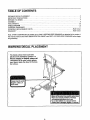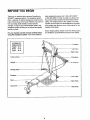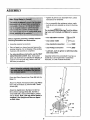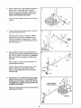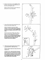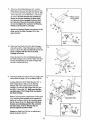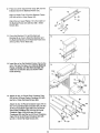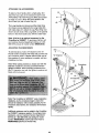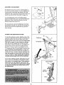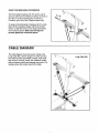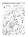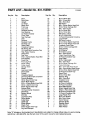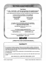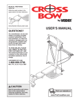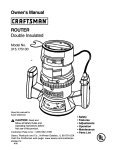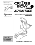
1
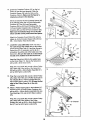
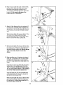
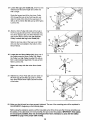
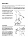
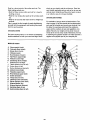
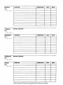
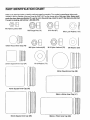
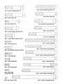
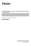
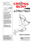
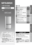
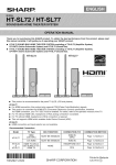
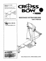
Model No. 831.153951
Serial No.
Write the serial number _nthe
space above for future reference
Serial Number Decal (under seat)
• .."
RESISTANCE SYSTEM EXERCISER
User's Manual
Sears, Roebuck and Co., Hoffman Estates, IL 60179
TABLE OF CONTENTS
WARNING DECAL PLACEMENT ..........................................................
IMPORTANT PRECAUTIONS .............................................................
BEFORE YOU BEGIN ...................................................................
ASSEMBLY ...........................................................................
ADJUSTMENTS ......................................................................
CABLE DIAGRAM .....................................................................
EXERCISE GUIDELINES ...............................................................
ORDERING REPLACEMENT PARTS ................................................
WARRANTY ..................................................................
2
3
4
5
13
16
17
Back Cover
Back Cover
Note: A PART IDENTIFICATION CHART and a PART LIST/EXPLODED DRAWING are attached in the center of
this manual. Remove the PART IDENTIFICATION CHART and PART LIST/EXPLODED DRAWING before beginning assembly.
WARNING DECAL PLACEMENT
The decals shown here have been
placed on the resistance system. If a
decal is missing or iUeglble, please call
1-800-999-3756 to order a free replacement decal, Apply the decal in the location shown.
hands and
of
"IIS area.
• Misuseofthisproductmay resultIrtsedous_jury,
• Read user'smanualand followall warnings
end operatinginstructions
pdorto use.
• Do notallowchildrenonor aroundmachine,
or removed.
2
IMPORTANT PRECAUTIONS
3
BEFORE YOU BEGIN
after reading this manual, call 1-800-4-MY-HOME ®
(1-800-469-4663). To help us assist you, please note
the product model number and serial number before
calling. The model number is 831.153951. The serial
number can be found on a decal attached to the resist-
Thank you for selecting the innovative CrossBow by
WELDER" resistance system. The resistance system
offers a selection of stations designed to develop every
major muscle group of the body. Whether your goal is to
tone your body, build dramatic muscle size and
strength, or improve your cardiovascular system, the
resistance system will help you to achieve the specific
results you want.
ance system (see the front cover of this manual for the
location of the decal).
Before reading further, please review the drawing below
and tamiliadze yourselt with the parts that are labeled.
For your benefit, read this manual carefully before
using the resistance system. If you have questions
ASSEMBLED
DIMENSIONS:
Height: 82 in.
Width:
64 in.
Depth:
Crossbar
Lat Tower
80 in.
High Pulley
Fulcrum Knob
Crossbows
Upright
Storage Knob
Backrest
Low Pulley
Seat
Base Plate
Leg Lever
Seat Knob
4
ASSEMBLY
• Tighten all parts as you assemble them, unless
instructed to do otherwise,
• As you assemble the resistance system, make
sure alt parts are oriented as shown in the drawings.
The included _AIlen wrencheeeeeeeeee_
and the following tools (not included) are required for assemb:y:
• Two adjustable wrenches
Before beginning assembly, carefully read the
following information and instructions:
• One rubber mallet
• Assembly requires two persons.
• One standard screwdriver
• Place all parts in a cleared area and remove the
packing materials. Do not dispose of the packing
materials until assembly is completed.
• One Phillips screwdriver
_=_
• Lubricant, such as grease or petroleum jelly,
and soapy water.
• For help identifying smafl parts, use the PART
IDENTIFICATION CHART. Note: Some small
parts may have been pre-attached for shipping. If
a part is not in the parts bag, check to see if it
has been pre-attached,
Assembly will be more convenient if you have a
socket set, a set of open-end or closed-end
wrenches, or a set of ratchet wrenches.
1.
Press two 50mm Square Inner Caps (98) into the
Base (1).
Attach two Plastic Feet (53) and two Large Plastic
Feet (t02) to the Base (1) with four M4 x 16mm
Screws (62).
Attach the Upright (3) to the Base (1) with two
M10 x 66mm Carriage Bolts (83), two M10 x
72mm Bolts (64), and four M10 Nylon Locknuts
(76) as shown. Note: This step will be easier to
complete if the Upright and Base are tipped
on their sides,
5
2.
Attach a Wheel (31) to the outside of the Base (1)
with an M10 x 108mm Bolt (81), three M10
Washers (75), and an M10 Nylon Lecknut (76).
Do not overtighten the Nylon Locknut; the
Wheel must be able to turn easily.
2
Attach the other Wheel (not shown) in the same
manner.
7i
75
75
75
47
T&T±T-T.
Press a 36ram x 64mm Inner Cap (41) into each
end of the Cross Tube (11).
3,
Orient the Cross Tube (11) as shown, with the
welded tubes at the bottom. Attach the Cross
Welded
Tube to the Upright (3) with two M10 x 140ram
Carriage Bolts (73), two M 10 Washers (76), and
two M10 Nuts (47).
11
41
Press a 38mm x 76mm Inner Cap (99) into the
top of the Front Leg (6). Press the Front Leg Foot
(27) onto the bottom of the Front Leg. Note that
the front of the Front Leg Foot is taller than
the back.
4,
4
99
76
Hook
Press a 38ram x 76mm Inner Cap (99) into the
end of the Bench Rail (5),
76
Attach the Bench Rail (5), with the hook on the
bottom, to the Front Leg (6) with two M10 x
53mm Carriage Bolts (61) and two M10 Nylon
Locknuts (76).
,
Lubricate an M10 x 103ram Bolt (66) with grease.
Attach the Bench Rail (5) to the Upright (3) with
the Bolt and an M10 Nylon Locknut (76). Do not
overUghten the Locknut; the Bench Rail must
be able to pivot easily.
3O
Insert the bolt
through this hole
76
Tighten the Storage Knob (30) into the Upright (3)
and the Bench Rail (5).
Lubricate
6
Attach the Lat Tower (4) to the Upright (3) with
four M10 x 25mm Button Head Bolts (87), and
four M10 Lock Washers (103).
.
6
Attach the Name Plate (89) to the Lat Tower (4)
with two M4 x 16ram Screws (62).
1 03 87
103
-3
Press a 38ram Round Inner Cap (38) into each
end of the Lat Tower Crossbar (10).
7,
7O
65
Attach two Eyebolts (34) to the Lat Tower
Crossbar (10) with two M8 Washers (59) and two
M8 Nylon Locknuts (65). Do not overtighten the
Locknuts; the Eyebolts must be able to rotate
freely.
75
59
10
65
Attach the Lat Tower Crossbar (10) to the Lat
Tower (4) with two M10 x 65ram Button Head
Bolts (70), two M10 Washers (75), and the
Crossbar Cover (93), Be sure that the Eyebolts
(34) are oriented as shown in the inset drawing. If they are not, turn the Lat Tower
Crossbar around and reattach it.
34
Side View
10,,
.
Attach the Leg Lever Bumper (55) to the Front
Leg (6) with an M4 x 19mm Screw (77).
Lubricate
56_
Press two 45mm Square Inner Caps (42) into the
Leg Lever (7).
42_
Lubricate an M10 x 68ram Bolt (56) with grease.
Orient the Leg Lever (7) with the slot on the side
shown. Attach the Leg Lever to the Front Leg (6)
with the Bolt and an M10 Nylon Locknut (76). Do
not overtighten the Nylon Locknut; the Leg
Lever must be able to pivot easily,
76
42
7
9.
Attach two 8mm Metal Spacers (97), a 60mm
Metal Spacer (39), and two Bearing Wheels (46)
to one end of the Seat Carriage (12) with an M8 x
104mm Bolt (60) and an M8 Nylon Locknut (65)
as shown. Be sure the parts are oriented as
shown in the inset drawing; the Seat Knob
(not shown) will not engage the Bench Rail
(not shown) if they are incorrectly oriented,
Do not overtighten the Locknut; the Bearing
Wheels must be able to roll easily.
9
Attach two Bearing Wheels (not shown) to the
other end of the Seat Carriage (12) in the
same manner.
97
_1
10. Attach the Seat Knob (45) to the Seat Carriage
(12) with two M6 x 13mm Bolts (92) and two M6
Nylon Locknuts (69). Be sure that the slot in the
Knob is aligned with the slot in the Seat
Carriage, as shown.
46
10
Orient the Seat (13), the Seat Backing (9), and
the Seat Carriage (12) as shown. Attach the Seat
and the Seat Backing to the Seat Carriage with
four M6 x 16ram Bolts (82).
l
Slots
11. Pull out the Seat Knob (45) as far as it will go, and
set the Seat Carriage (12) on the Bench Rail (5).
11
19
Loosely attach two 8mm Metal Spacers (97), a
60mm Metal Spacer (39), and two Bearing
Wheels (46) to the center holes in the Seat
Carriage (12) with two M8 Flange Nuts (19) and
the M8 x 114mm Bolt (57). Make sure that the
serrated edge of the Flange Nuts are against
the Seat Carriage.
13
57
While a second person presses down on the Seat
(13), hold the wheel assembly firmly against the
bottom of the Bench Rail (5) and properly tighten
the M8 Flange Nuts (19). Make sure that three
threads are extending past the Nut, and that
the wide sides of all six Wheels (46) are
pressed against the Bench Rail.
Adjustment Hole
46
97
46
Engage the Seat Knob (45) into an adjustment
hole in the Bench Rail (5).
8
12. Press two 25mm Square Inner Caps (54) into the
indicated end of the Backrest Frame (15),
!2
15
Attach a Plastic Foot (53) to the Backrest Frame
(15) with an M4 x 16mm Screw (62).
Attach the two Guard Plates (17) to the inside of
the Backrest Frame (15) with four M4 x 16mm
Screws (62).
62
13. Orient the Backrest (14) and the Backrest
Backing (8) as shown. Attach the Backrest and
the Backrest Backing to the Backrest Frame (15)
with four M6 x 45mm Bolts (58).
13
14. Insert the rod on the Backrest Frame (15) into the
slot in the Seat Carriage (12). Hold the Backrest
Frame vertically over the Seat Carriage and
slide the rod into the slot, as shown in the
inset drawing.
15. Attach the two 10-Pound Short Crossbow Caps
(20) to the 10-Pound Center Crossbow (44) with
two M4 x 12mm Flat Head Screws (85).
15
96
Attach the two 1e-Pound Crossbow Caps (101) to
the 10-Pound Removable Crossbow (67), the two
20-Pound Crossbow Caps (88) to the 20-Pound
Removable Crossbow (36), the tour 80-Pound
Crossbow Caps (100) to the two 80-Pound
Crossbows (95), and the two 40-Pound Crossbow
Caps (79) to the 40-Pound Crossbow (96) with
ten M4 x 12ram Flat Head Screws (85).
lOO
9
16. Locate the Crossbow Fulcrum (18) on the Lat
16
86
Tower (4) (see the inset drawing). Slide the
Crossbow Spacer (35) onto the rods on the
Crossbow Futcrum. Make sure the Spacer is
oriented as shown in the drawing,
Edges
Set the Crossbows into the Crossbow Spacer (35)
96
in the following order: the 10-Pound Removable
Crossbow (67), the 20-Pound Removable
Crossbow (36), an 80-Pound Crossbow (95), the
10-Pound Center Crossbow (44), an 80÷Pound
Crossbow (95), and the 40-Pound Crossbow (96).
Make sure the indicated rings are on the side
shown and the arrows point toward the Spacer.
Rings or
this side
95
Rods 67
Attach the Crossbow Cover Plate (72), with the
edges up, to the Crossbow Spacer (35) with two
M8 x 19ram Button Head Screws (86).
17
80
17. Locate the Long Cable (80). Insert one end of
the Cable through the welded tube on the indicated end of the Cross Tube (11) and then through a
Swivel Arm (22). If necessary, use the tip of a
screwdriver to pull the end ot the Cable out of the
Swivel Arm. Be sure the Cable is on the indicated side of the welded rod in the Swivel Arm.
71
104
Rod
Insert the Swivel Arm (22) into the welded tube
on the Cross Tube (11). Secure the Swivel Arm
with an M4 x 5mm Screw (104).
Wrap the Long Cable (80) around a 90mm Pulley
(28). Attach the Pulley inside of the Swivel Arm
(22) with an MIO x42mm Button Head Bolt (71)
and an MIO Nylon Locknut (76).
18
Flat
Edge
18. Wrap the Long Cable (80) around a 90mm Pulley
(28). Attach the Pulley and a Pulley Guard (29) to
the indicated MIO x 140ram Carriage Bolt (73)
with an MI0 Nylon Locknut (76). Be sure the flat
edge of the Pulley Guard is on the side
shown.
29 76
28
19, Attach a Pulley Housing (94) to the indicated "U"channel on the 10-Pound Center Crossbow (44)
with an MIO x 102mm Button Head Bolt (24), two
Pivot Bushings (74), and an M10 Nylon Locknut
(76).
Wrap the Long Cable (80) around a 90mm Pulley
(28). Attach the Pulley inside of the Pulley
Housing (94) with an M10 x 42ram Button Head
Bolt (71) and an M10 Nylon Looknut (76).
10
20. Wrap the Long Cable (80) under a 90mm Pulley
(28) as shown. Attach the Pulley and a Pulley
Guard (29) to the Upright (3) with an M10 x
113mm Button Head Bolt (40) and an M10 Nylon
Locknut (76). Be sure the flat edge of the
Pulley Guard is on the bottom.
2O
8O
Flat
Edge
21. Attach a Pulley Housing (94) to the indicated "U"channel on the 10-Pound Center Crossbow (44)
with an M10 x 102ram Button Head Bolt (24), two
Pivot Bushings (74), and an M 10 Nylon Locknut
(76).
21
Wrap the Long Cable (80) around a 90mm Pulley
(28). Attach the Pulley inside of the Pulley
Housing (94) with an MIO x 42ram Button Head
Bolt (71) and an M10 Nylon Locknut (76).
24
71
28
22. Wrap the Long Cable (80) around a 90mm Pulley
(28). Attach the Pulley and a Pulley Guard (29) to
the indicated M10 x 140mm Carriage Bolt (73)
with an M10 Nylon Locknut (76). Be sure the flat
edge of the Pulley Guard is on the side
shown,
22
28
Edge
23. Make sure there are no Crossbows (not shown)
under the "U"-channels on the 10-Pound Center
Crossbow (not shown). Have a second person
pull on the Long Cable (80) to create slack in the
Cable.
23
Insert the end of the Long Cable (80) through the
welded tube on the indicated end of the Cross
Tube (11) and then through the remaining Swivel
Arm (22). Be sure the Cable is on the indicated
side of the welded rod in the Swivel Arm.
Rod
80..
Insert the Swivel Arm (22) into the welded tube
on the Cross Tube (11). Secure the Swivel Arm
with an M4 x 5mm Screw (104).
11
Wrap the Long Cable (80) around a 90ram Pulley
(28). Attach the Pulley inside of the Swivel Arm
(22) with an M10 x 42mm Button Head Bolt (71)
and an M10 Nylon Locknut (76).
11
24. Locata the Leg Lever Cable (32), which has two
ends that are the same length and a third end
that is longer.
24
Route the longest end of the Leg Lever Cable
(32) through the hole in the Front Leg (6), and
attach it inside of the hole in the Leg Lever (7)
with an M10 x 60mm Bolt (63) and an M10 Nylon
Locknut (76).
32
_,j76
25. Attach a 90mm Pulley (28) inside of the hole in
the Front Leg (6) with an M10 x 91ram Bolt (90),
two 26ram Spacers (52), two M10 Washers (75),
and an M10 Nylon Locknut (76). Be sure the
Pulley is above the Leg Lever Cable (32).
25
6
90
Slide the two free ends of the Leg Lever Cable
(32) onto the hook welded to the bottom of the
Bench Rail (5).
Hook
76
26. Locate the two Short Cables (33). Wrap one of
the Cables around a 90mm Pulley (28). Attach
the Pulley to a High Pulley Housing (21) with an
M10 x 42mm Button Head Bolt (71) and an M10
Nylon Locknut (76).
26
76
Repeat this step with the other Short Cable
(33).
28
27. Slide the four Foam Pads (26) onto the tubes on
the Front Leg (6) and the Leg Lever (7). Press
four 19mm Round Inner Caps (78) into the ends
of the tubes.
27
26
26
26
28. Make sure that all parts have been properly tightened. The use of the remaining parts will be explained in
ADJUSTMENTS, beginning on the following page.
Before using the resistance system, pull the long cable a few times to be sure that it moves smoothly over
the pulleys. If the cable does not move;smoothly, find and correct the problem. IMPORTANT:. If the cables
are not properly installed, they may be damaged when heavy resistance is used. See the CABLE
DIAGRAM on page 16 for proper cable routing.
12
ADJUSTMENTS
This section explains how to adjust the resistance system. See the EXERCISE GUIDELINES on page 17 for
important information about how to get the most benefit from your exercise program. Also, refer to the accompanying exercise guide to see the correct form for each exercise.
Make sure all parts are properly tightened each time you use the resistance system. Replace worn parts immediately. The resistance system can be cleaned with a damp cloth and a mild, non-abrasive detergent. Do not use
soTvents. The crossbows can be cleaned with a vinyl and rubber protectant, available at an automotive or department store.
ATTACHING THE HIGH PULLEYS AND LEG LEVER
34
To use a high pulley, slide the hook on the High
Pulley Housing (21) onto the Eyebolt (34). Attach the
end of the Short Cable (33) without the ball to the end
of the Long Cable (80) with a Cable Clip (51). Attach
the other high pulley in the same manner.
To use the Leg Lever (not shown), attach the two
ends of the Leg Lever Cable (32) to the ends of the
Long Cable (80) with two Cable Clips (51).
Remove the high pulleys, and detach the Leg Lever
Cable (32), when not in use. Store the ends of the
Leg Lever Cable on the hook under the Bench Rail
(not shown).
Hook
ADJUSTING THE SEAT
The Seat (13) can be secured in any of four positions
on the Bench Rail (5). To move the Seat, pull the
Seat Knob (45) out as far as it will go, and slide the
Seat to the desired position. Engage the Seat Knob
into an adjustment hole in the Bench Rail. Note: It
may be necessary to lift up on the Seat in order to
engage the Seat Knob,
13
To perform row exercises, the leg press strap must be
attached to the long cable (see ATTACHING THE
ACCESSORIES, on page 14), and the Seat (13) must
be able to roll along the Bench Rail (5). First, remove
the backrest from the seat frame (see ADJUSTING
THE BACKREST on page 15). Then, pull the Seat
Knob (45) out as far as it will go, and turn the Knob
so that the pin rests at the end of the "L"-shaped slot
(see the inset drawing).
12
Pin
13
45
A'I-rACHING THE ACCESSORIES
To attach a Short Handle (49) to a high pulley, first
attach the high pulley to the resistance system (see
ATTACHING THE HIGH PULLEYS AND LEG LEVER
on page 13). Then, attach the Short Handle to the
Short Cable (33) with a Cable Clip (51).
49
The Long Handles (not shown) and the Ankle Strap
(not shown) can be attached to the Long Cable (80)
with Cable Clips (5!). Attach the Leg Press Strap (not
shown) to both ends of the Long Cable, or the optional
lat bar to the Short Cables (33), with two Cable Clips.
Note: A lat bar is an optional accessory for the
CrossBow by WELDER". To purchase a lat bar, call
our Customer Service Department toll-free at 1-800999-3756 and ask for model number WEMC04420.
ADJUSTING THE RESISTANCE
To add resistance, hold a "U"-channel on the 10Pound Center Crossbow (44) firmly and push the end
of a crossbow under it. Repeat with the other end of
the crossbow. If more resistance is needed, add one
crossbow at a time.
Note: When adding resistance, always start with the
heaviest crossbow to be used, and finish with the
lightest crossbow. When removing crossbows from
the "U"-channels, start with the Ifghtest crossbow and
finish with the heaviest.
Crossbows
Note: The CrossBow by WELDER" uses progressive
resistance. As the crossbows begin to bend, the
amount of resistance will increase gradually. As the
crossbows bend further, the resistance will increase
rapidly.
Additional resistance can be added to the CrossBow
by WEIDEW" resistance system. To purchase more
resistance, call our Customer Service Department
toll-free at 1-800-999-3756 and asking for model
number WEMC06420 (100-Pound Power Pak) or
WEMC09420 (200-Pound Power Pak).
14
ADJUSTING THE BACKREST
The Backrest (14) can be used in a level position or
one of three inclined positions. To use the Backrest in
a level position, secure the Seat Frame (12) to the
adjustment hole in the Bench Rail (5) next to the Front
Leg (6) (see ADJUSTING THE SEAT on page 13).
14
To use the Backrest (14) in an inclined position,
secure the Seat Frame (12) to one of the other three
adjustment holes in the Bench Rail (5). Rest the
Backrest against the Upright (3).
For row exercises, remove the Backrest (14). Hold
the Backrest vertically over the Seat (13) and lift the
rod out of the slot in the Seat Frame (12) (see the
inset drawing).
12
STORING THE RESISTANCE SYSTEM
To store the resistance system, slide the ends of the
Leg Lever Cable (32) onto the hook on the bottom of
the Bench Rail (5). Be sure the Seat (13) is in the
position closest to the Front Leg (6) (see ADJUSTING
THE SEAT on page 13). Next, remove the Storage
Knob (30) from the Upright (3). Lift the Front Leg
toward the Lat Tower Crossbar (10), and tighten the
Storage Knob into the side of the Upright and the
Bench Rail. Remove all of the crossbows from the
"U"-channels on the 10-Pound Center Crossbow (44)
(see ADJUSTING THE RESISTANCE on page 14).
Finally, loosen the Fulcrum Knob (43) and pull it out
as far as it will go. Turn the crossbow assembly vertically and engage the Fulcrum Knob into the fulcrum
on the Lat Tower (4). Note; Storing the crossbows
vertically will prolong the life of the crossbows.
To move the resistance system, place the toe of your
shoe on the end of the Base (1) and hold the resistance system in the indicated area. Tilt the resistance
system back onto the Wheels (31) and roll it to the
new location. Be careful not to let the Front Leg (6)
or Leg Lever (7) pinch your hands when you tilt
the system back.
Crossbows
"U"-Channel
32
Stored Position
Hold in
this area
USING THE REMOVABLE CROSSBOWS
The Removable Crossbows (36, 67) can be used to
exercise apart from the resistance system, as shown in
the video or on the exercise guide. To _emove a
Crossbow, pull it out of the Crossbow Spacer (35).
67 36
To replace the Removable Crossbows (36, 67), slide
them into the Crossbow Spacer (35) from the side
shown, so that the arrows on the rings point toward
the Crossbow Spacer. Make sure the rings are
pushed against the Crossbow Spacer.
CABLE DIAGRAM
The cable diagram shows the proper routing of the
Long Cable (80). Use the diagram to make sure that
the cable has been assembled correctly. If the cable
has not been correctly routed, the resistance system
will not function propedy and damage may occur. The
numbers show the correct route for the cable.
Long Cable (80)
EXERCISE GUIDELINES
THE FOUR BASIC TYPES OF WORKOUTS
PERSONALIZING YOUR EXERCISE PROGRAM
Muscle Building
To increase the size and strength of your muscles,
push them close to their maximum capacity. Your muscles will continually adapt and grow as you progressively increase the intensity of your exercise. You can
adjust the intensity level of an individual exercise in
two ways:
• by changing the amount of resistance used
• by changing the number of repetitions or sets performed. (A "repetition" is one complete cycle of an
exercise, such as one sit-up. A "set" is a series of
repetitions.)
Determining the exact length of time for each workout,
as well as the number of repetitions or sets completed,
is an individual matter. It is important to avoid overdoing it during the first few months of your exercise program. You should progress at your own pace and be
sensitive to your body's signals. If you experience pain
or dizziness at any time while exercising, stop immediately and begin cooling down. Find out what is wrong
before continuing. Remember that adequate rest and a
proper diet are important factors in any exercise program.
WARMING UP
The proper amount of resistance for each exercise
depends upon the individual user. You must gauge
your limits and select the amount of resistance that is
right for you. Begin with 3 sets of 8 repetitions for each
exercise you perform. Rest for 3 minutes after each
set. When you can complete 3 sets of 12 repetitions
without difficulty, increase the amount of resistance.
Begin each workout with 5 to 10 minutes of stretching
and light exercise to warm up. Warming up prepares
your body for more strenuous exercise by increasing
circulation, raising your body temperature and delivering more oxygen to your muscles.
WORKING OUT
Toning
You can tone your muscles by pushing them to a moderate percentage of their capacity. Select a moderate
amount of resistance and increase the number of repetitions in each set. Complete as many sets of 15 to
20 repetitions as possible without discomfort. Rest for
1 minute after each set. Work your muscles by completing more sets rather than by using high amounts of
resistance.
Each workout should include 6 to 10 different exercises. Select exercises for every major muscle group,
emphasizing areas that you want to develop most. To
give balance and variety to your workouts, vary the
exercises from session to session.
Schedule your workouts for the time of day when your
energy level is the highest. Each workout should be
followed by at least one day of rest. Once you find the
schedule that is right for you, stick with it.
Weight Loss
To lose weight, use a low amount of resistance and
increase the number of repetitions in each set.
Exercise for 20 to 30 minutes, resting for a maximum
of 30 seconds between sets.
EXERCISE FORM
Maintaining proper form is an essential part of an
effective exercise program. This requires moving
through the full range of motion for each exercise, and
moving only the appropriate parts of the body.
Exercising in an uncontrolled manner will leave you
feeling exhausted. On the exercise guide accompanying this manual you will find photographs showing the
correct form for several exercises, and a list of the
muscles affected. Refer to the muscle chart on page
18 to find the names of the muscles.
Cross Training
Cross training is an efficient way to get a complete and
well-balanced fitness program. An example of a balanced program is:
• Plan strength training workouts on Monday,
Wednesday, and Friday.
• Plan 20 to 30 minutes of aerobic exercise, such as
running on a treadmill or riding on an elliptical or
exercise bike, on Tuesday and Thursday.
• Rest from both strength training and aerobic exercise
for at least one full day each week to give your body
time to regenerate.
The repetitions in each set should be performed
smoothly and without pausing. The exertion stage of
each repetition should last about half as long as the
return stage. Proper breathing is important. Exhale
during the exertion stage of each repetition and inhale
during the return stroke. Never hold your breath.
The combination of strength training and aerobic exercise will reshape and strengthen your body, plus develop your heart and lungs.
17
Rest for a short period of time after each set. The
ideal resting periods are:
° Rest for three minutes after each set for a muscre
building workout.
• Rest for one minute after each set for a toning workout.
slowly as you stretch and do not bounce. Ease into
each stretch gradually and go only as far as you can
without strain. Stretching at the end of each workout
is an effective way to increase flexibility.
STAYING MOTIVATED
• Rest for 30 seconds after each set for a weight loss
workout.
For motivation, keep a record of each workout. The
chart on page 19 of this manual can be photocopied
and used to schedule and record your workouts. List
the date, the exercises performed, the resistance
used, and the numbers of sets and repetitions completed. Record your weight and key body measurements at the end of every month. Remember, the key
to achieving the greatest results is to make exercise a
regular and enjoyable part of your everyday life.
Plan to spend the first couple of weeks familiarizing
yourself with the equipment and learning the proper
form for each exercise.
COOLING DOWN
End each workout with 5 to 10 minutes of stretching.
Include stretches for both your arms and legs. Move
MUSCLE CHART
A.
B,
C.
D,
E.
F.
G.
H.
I.
J.
K.
L.
M.
N.
O.
P.
Q.
R.
S.
T,
U.
V.
W,
Stemomastoid (neck)
Pectoralis Major (chest)
Biceps (front of arm)
Obliques (waist)
Brachioradials (forearm)
Hip Flexors (upper thigh)
Abductor (outer thigh)
Quaddceps (front of thigh)
Sartorius (front of thigh)
Tibialis Anterior (front of calf)
Soleus (front of calf)
Rectus Abdominus (stomach)
Adductor (inner thigh)
Trapezius (upper back)
Rhomboideus (upper back)
Deltoid (shoulder)
Triceps (back of arm)
Latissimus Dorsi (mid back)
Spinae Erectors (lower back)
Gluteus Medius (hip)
Gluteus Maximus (buttocks)
Hamstring (back of leg)
Gastrocnemius (back of calf)
c\
R
S
18
MONDAY
EXERCISE
RESISTANCE
SETS
REPS
RESISTANCE
SETS
REPS
RESISTANCE
SETS
REPS
Date:
/
/
AEROBIC EXERCISE
TUESDAY
Date:
/
/
WEDNESDAY
EXERCISE
Date:
/
/
THURSDAY
Date:
/
/
AEROBIC EXERCISE
EXERCISE
FRIDAY
Date:
/
/
I
Make photocopies of this page for scheduling and recordingyour workouts.
19
PART IDENTIFICATION
CHART
Refer to the drawings below to identify small parts used in assembly. The number in parentheses below each
drawing is the key number of the part, from the PART LIST on the reverse side of this page. Note: Some small
parts may have been pre-attached. If a part is net in the parts bag, check to see if it has been pre-attached.
If a part is missing, call toll-free 1-800-999-3756.
©@
M6 Nylon Locknut
(69)
M8 Flange Nut (19)
M10 Nut (47)
M10 Lock Washer (103)
19mm Round Inner Cap (78)
M8 Nylon Locknut
25mm Square Inner Cap (54)
(65)
M10 Washer
M 10 Nylon Locknut
(76)
M8 Washer
(59)
(75)
38ram Round Inner Cap (38)
J
45mm Square Inner Cap (42)
38mm x 64mm Inner Cap (41)
ii
50mm Square Inner Cap (98)
38mm x 76mm Inner Cap (99)
M10 x 65mm Button Head Bolt (70)
M10 x 53mmCarraigeBolt (61)
B
M10 x 68mm Bolt (56)
M10 x 60ram Bolt (63)
M6 x 45ram Bolt (58)
M10 x 66mm Carriage
Bolt (83)
_\\\\\\\
[}
M10 x 72mm Bolt (64)
M10 x 42mm Button Head Bolt (71)
_\\\\\\\l
M10 x 91mm Bolt (90)
M10 x 25mm Button Head Bolt (87)
_\\\\\\\\\\\\\\\\\\\\\\\\\\\\\\\_
M10 x 103mm Bolt (66)
M4 x 19mm Screw (77)
_\\\\\\\\\\\\\\\\ I
[_
M8 x 104mm Button Head Bolt (60)
M8 x 19mm Button Head Screw (86)
[}
M10 x 102mm Button Head Bolt (24)
M6 x 16mm Bolt (82)
M4 x 16mm Screw (62)
M10 x 1OSmm Bolt (81)
\\\\\\_
M8 x ll4mm
M6 x 13mm Screw (92)
Bolt (57)
D
_\\\\\\\t
M4 x 12mm Flat
Head Screw (85)
®
h\\\\\\
M10 x 113mm Button Head Bolt (40)
_\\\\\\
1,
M4 x 5mm Screw (104)
M10 x 140mm Carriage
Bolt (73)L_
EXPLODED DRAWING--Model No. 831.153951
m2o2B
75
86
lOO
85
lOO
96
95
88
79
44
34
36
21
71
101
67
_4
53 62
15
,
62
,t--'3_'_' ,_43
v,
76_.
94 76
74_.._Z ..,,/
71.........._
_, ._
r _74
87
9
28
J
17
28 76
I_k_28 _..24
..-'"97
57
60\
24
i
"-.
60
82
82
.....--"
---'" 29
73___i
76-.. t
45
.<k#_6
80
71 _
28
r
97
74 9474
40
_
5
25
76
64
46
75
47
41
25
23
71
46
22
76
99
,_
81 75
76
76
98
6
75
78
, 31
81
102"_
62
42
,_27
62
83
51
48
PART LIST--Model No. 831.153951
Key No.
Qty.
1
2
3
4
5
6
7
8
9
10
11
12
13
14
15
16
17
18
19
20
21
22
23
24
25
26
27
28
29
30
31
32
33
34
35
36
37
38
39
40
41
42
43
44
45
46
47
48
49
50
51
52
53
54
55
1
1
1
1
1
1
1
1
1
1
1
1
1
1
1
1
2
1
2
2
2
2
2
2
4
4
1
10
3
1
2
1
2
2
1
1
2
2
3
1
2
2
1
1
1
6
2
1
2
1
4
2
3
2
1
Description
Base
Base Plate
Upright
Lat Tower
Bench Rail
Front Leg
Leg Lever
Backrest Backing
Seat Backing
Lat Tower Crossbar
Cross Tube
Seat Carriage
Seat
Backrest
Backrest Frame
Backrest Cap
Guard Plate
Crossbow Fulcrum
M8 Flange Nut
10-Pound Short Crossbow Cap
High Pulley Housing
Swivel Arm
Grip Tape
M10 x 102mm Button Head Bolt
Arm Bushing
Foam Pad
Front Leg Foot
90mm Pulley
Pulley Guard
Storage Knob
Wheel
Leg Lever Cable
Short Cable
Eyebolt
Crossbow Spacer
20-Pound Removable Crossbow
Fulcrum Bushing
38mm Round Inner Cap
60mrn Metal Spacer
M10 x 113ram Button Head Bolt
38turn x 64turn Inner Cap
45mm Square Inner Cap
Fulcrum Knob
10-Pound Center Crossbow
Seat Knob
Bearing Wheel
M10 Nut
Leg Press Strap
Short Handle
Ankle Strap
Cable Clip
26mm Spacer
Plastic Foot
25rnm Square Inner Cap
Leg Lever Bumper
R 202B
Key No,
Qty.
56
57
58
59
60
61
62
63
64
65
66
67
68
69
70
71
72
73
74
75
76
77
78
79
80
81
82
83
84
85
86
87
88
89
90
91
92
93
94
95
96
97
98
99
100
101
102
103
104
#
#
#
#
#
1
1
4
2
2
2
15
1
2
4
1
1
2
2
2
6
1
2
4
12
23
1
4
2
1
2
4
2
1
12
2
4
2
1
1
1
2
1
2
2
1
6
2
2
4
2
2
4
2
1
I
1
2
1
Description
MIO x 68mm Bolt
M8 x 114mm Bolt
M6 x 45mm Bolt
M8 Washer
M8 x 104mm Button Head Bolt
M10 x 53ram Carriage Bolt
M4 x 16mm Screw
M10 x 60mrn Bolt
M10 x 72rnm Bolt
M8 Nylon Locknut
MIO x 103mm Bolt
10-Pound Removable Crossbow
Long Handle
M6 Nylon Locknut
MIO x 65mm Button Head Bolt
M10 x 42rnrn Button Head Bolt
Crossbow Cover Plate
M10 x 140mm Carriage Bolt
Pivot Bushing
M10 Washer
M10 Nylon Locknut
M4 x 19ram Screw
19ram Round Inner Cap
40-Pound Crossbow Cap
Long Cable
M10 x-108ram Bolt
M6 x 16mm Bolt
MIO x 66mm Carriage Bolt
Fulcrum Endcap
M4 x 12mm Flat Head Screw
M8 x 19mm Button Head Screw
M10 x 25mm Button Head Bolt
20-Pound Crossbow Cap
Name Plate
MIO x 91mm Bolt
Retainer Ring
M6 x 13mrn Bolt
Crossbar Cover
Pulley Housing
80-Pound Crossbow
40-Pound Crossbow
8mm Metal Spacer
50mm Square Inner Cap
38ram x 76mm Inner Cap
80-Pound Crossbow Cap
10-Pound Crossbow Cap
Large Plastic Foot
MIO Lock Washer
M4 x 5mm Screw
User's Manual
Exercise Guide
Exercise Decal
Allen Wrench
Allen Wrench
Note: "#" indicates a n_n-illustrated part. Specifications are subject to change without notice. If a part Is missing,
call toll-free 1-800-999-3756. See the back cover of the user's manual to order replacement parts.
YourHome
For repair - in your home - of all major brand appliances, lawn and garden equipment,
or heating and cooling systems, no matter who made it, no matter who sold itl
For the replacement
parts, accessories, and user's manuals that you need to do-it-yourself.
For Sears professional installation of home appliances
and items like garage door openers and water heaters.
1-800-4-MY-HOM
E®
Anytime, day or night
(U.S.A.and Canada)
www.sears.ca
(1-800-469-4663)
www.sears.com
Our Home
For repair of carry-in products like vacuums, lawn equipment,
and electronics, call or go on-line for the location of your nearest
Sears Parts and Repair Center.
1-800-488-1222
Anytime, day or night (U.S.A. only)
www.sears.com
_:_,_
N
_ '
To purchase a protection agreement (U.S.A.)
or maintenance agreement (Canada) on a product serviced by Sears:
1-800-827-6655
(USA)
1-800-361-6665
_
(Canada)
_::'_°_:_
Pare pedir servicio de reparacibn a domicilio, y para ordenar piezas:
_i_i_:_i:i_i:i
® RegisteredTrademark/ "mTrademarkI s_Service Markof Sears,Roebuck andCo.
® Mama Reglstrade/ _ M_rca de F_bd¢_/ _ Mama de Se_clo de Sears, Roebuckand Co.
WARRANTY
For one year from the date of purchase, if failure occurs due to defect in matedal or workmanship in
this RESISTANCE SYSTEM EXERCISER, contact the nearest Sears Service Center throughout the
United States and Sears will repair or replace the RESISTANCE SYSTEM EXERCISER, free of charge.
Parts wil! be replaced for five years.
This warranty does not apply when the RESISTANCE SYSTEM EXERCISER is used commercially or
for rental purposes.
This warranty gives you specific legal rights, and you may also have other rights which vary from state
to state.
Sears, Roebuck and Co., Dept 817WA, Hoffman Estates, IL 60179
J
J
Part No. 192240 R1202B
Pdnted in China © 2002 Sears, Roebuck and Co.