1
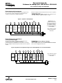
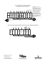
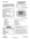
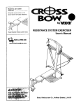
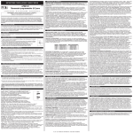
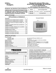
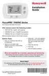
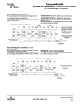
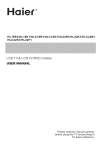
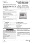
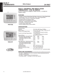
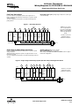
80 Series Thermostat
Wiring Diagrams for 1F83-0422 & 1F85-0422
Single Stage, Multi-Stage, Heat Pump
Heat Pump Connections
HEAT PUMP TYPE 1 (HP 1). Single stage compressor system; gas
or electric backup.
If you do not have a heat pump system, refer to figures 2 & 3.
Refer to equipment manufacturers’ instructions for specific system
wiring information.
You can configure the thermostat for use with the following heat
pump systems.
Figure 1 – Heat Pump Systems
Jumper
L
Y
O/B
Y2
W2
W/E
NOTE: If your system
does not provide an E
connection, jumper W2 to
W/E to use the Auxiliary
Heat in the Emergency
Mode.
Jumper
RC
RH
G
C
System
O
Heat Pump 1
(HP1)
Fault Indicator
or
System
Malfunction
Switch
Energized in
Cool Mode
B
Energized in
Heat, Off,
Emergency
Mode
Heat and
Cool Mode
No
1st Stage
Output
(Compressor)
Heat Mode
Emergency 2nd Stage.
Mode
Emergency
1st Stage
Mode 2nd
Stage
Blower/
Circulator
Fan Energized
Optional*
24 Volt 24 Volt
on Call for
24 Volt
Heat or Cool. (Hot)
(Hot)
(ComSet Elect/Gas Heat
Cool
mon)
Option for
Emergency
Mode
Comfort Alert II Module
or Similar System
Malfunction Module
* Common connection
required for fault or
malfunction indication.
NEUTRAL
120VAC
24VAC
HOT
CLASS II
TRANSFORMER
Single Stage and Multi-Stage Connections
Refer to equipment manufacturers’ instructions for specific system
wiring information.
This thermostat is designed to operate a single-transformer or twotransformer system.
You can configure the thermostat for use with the following fossil fuel
systems:
Single stage (SS 1) gas, oil or electric.
Multi-stage (MS 2) gas, oil or electric.
After wiring, see INSTALLER CONFIGURATION section for proper
thermostat configuration.
Figure 2 – Single Stage or Multi-Stage System (No Heat Pump) with Single Transformer
Jumper
L
O/B
Y
Y2
W/E
W2
G
RH
RC
C
System
Single
Stage 1
(SS1)
MultiStage 2
(MS2)
O
Energized Constantly
Fault
in
Indicator
Cool Mode
or
Cool Mode
System
1st Stage
Malfunction
B
Switch
Energized Constantly
in Heat, Off,
Emergency
Mode
No Output
No
Heat
Output Mode
1st Stage
Cool
Heat Mode
Mode
2nd Stage
2nd
Stage
Blower/
Circulator
Fan Energized
on Call for
Cool (and
Heat if
configured
for Electric
Heat)
Comfort Alert II Module
or Similar System
Malfunction Module
* Common connection
required for fault or
malfunction indication.
24 Volt 24 Volt Optional*
24 Volt
(Hot)
(Hot)
(ComHeat
Cool
mon)
NEUTRAL
120VAC
24VAC
HOT
CLASS II
TRANSFORMER
www.white-rodgers.com
PART NO. 37-9832A
0825
Figure 3 – Single Stage or Multi-Stage System (No Heat Pump) with Two
Transformers
Jumper
L
Y2
Y
O/B
W/E
W2
RH
G
RC
NOTE: If continuous backlight or
hardwired power input are desired but
do not function in both HEAT and COOL
modes, cut the heating transformer 24V
wires and tape off. Connect the neutral
circuit disconnected from the heating
transformer to the neutral circuit of the
cooling transformer. Disconnect the wire
to the RH terminal and install a jumper
between RH and RC. Depending on
the system requirements, replace the
cooling transformer with a 75VA class II
transformer if needed.
Remove Jumper Wire
between RH & RC
C
System
Single
Stage 1
(SS1)
O
B
Energized Energized
Fault
Constantly Constantly Cool Mode
Indicator
in Heat, Off, 1st Stage
in
(NOT
Cool Mode Emergency
USED)
Mode
MultiStage 2
(MS2)
No Output
No
Heat
Output Mode
1st Stage
Heat Mode
Cool
2nd Stage
Mode
2nd
Stage
Blower/
Circulator
Fan Energized 24 Volt 24 Volt Optional
on Call for
24 Volt
(Hot) (Hot)
Cool (and
(ComHeat Cool
Heat if
mon)
configured
for Electric
Heat)
NEUTRAL
120VAC
120VAC
24VAC
NEUTRAL
HOT
24VAC
COOLING
HOT
CLASS II
TRANSFORMER
HEATING
CLASS II
TRANSFORMER
Figure 4 – 3-Wire (SPDT) Heat Only Zone Valve Wiring
Jumper
6
Y
W
G
Opens
Valve
(4)
Blower/Circulator
Fan Energized
RH
RC
C
System
Single Stage
3-wire
Zone Valve
application
Closes
Valve
(6)
24 Volt 24 Volt
(Hot)
(Hot)
Cool
Heat
(5)
Constant
24 Volt
(Common)
NEUTRAL
120VAC
24VAC
HOT
CLASS II
TRANSFORMER
White-Rodgers is a division of Emerson
Electric Co.
The Emerson logo is a trademark and
service markof Emerson Electric Co.
St. Louis, Missouri
www.white-rodgers.com
Thermostat Série 80
Schémas de câblage pour 1F83-0422 et 1F85-0422
Un ou plusieurs étages, thermopompe
Raccordements de thermopompe
On peut configurer le thermostat pour fonctionner avec les systèmes
à thermopompe suivants :
THERMOPOMPE TYPE 1 (HP 1) : Système avec compresseur à un
seul étage ; installation d’appoint électrique ou à gaz.
Pour un système autre qu’à thermopompe, voir les figures 2 et 3.
Se reporter aux consignes du fabricant de l’équipement pour
connaître les instructions de câblage particulières.
Figure 1. Système à thermopompe
Cavalier
L
Y
O/B
Y2
W2
W/E
REMARQUE : Si le
système n’est pas doté
d’une borne E, relier avec
un cavalier les bornes
W2 et W/E afin d’utiliser
le chauffage d’appoint en
mode auxiliaire.
Cavalier
C
RC
RH
G
Système
O
Thermopompe 1
(HP1)
Indicateur ou
commutateur
d’anomalie
Alimentée en
climatisation
B
Alimentée en
chauffage, arrêt,
auxiliaire
Chauffage et
climatisation Aucune
sortie
- Étage 1
(compresseur)
Auxiliaire
- Étage 1
Chauffage
- Étage 2
Auxiliaire
- Étage 2
Ventilateur
alimenté sur
appel de
Chauffage Climatisation Facultatif*
chaleur ou de 24 volts
24 volts
24 volts
froid; régler
(tension)
(tension)
(commune)
ELE ou GAS
selon
l’auxiliaire
Module diagnostic
Comfort Alert II ou
similaire
* Raccordement commun
requis pour indicateur
d’anomalie.
NEUTRE
120 V CA
24 V CA
SOUS TENSION
TRANSFORMATEUR
DE CLASSE II
Raccordements pour installations
à un ou plusieurs étages
Un étage (SS 1) : à gaz, à mazout ou électrique ;
À étages (MS 2) : à gaz, à mazout ou électrique.
Après le câblage, passer à la section MENU DE CONFIGURATION
pour assurer le réglage du thermostat.
Se reporter aux consignes du fabricant de l’équipement pour
connaître les instructions de câblage particulières.
Le thermostat gère les installations à un ou deux transformateurs.
On peut configurer le thermostat pour fonctionner avec les systèmes
suivants :
Figure 2. Système à un ou plusieurs étages (sans thermopompe) et un seul transformateur
Cavalier
L
O/B
Y
Y2
W/E
W2
G
RH
RC
C
Système
O
Un étage
(SS1)
Indicateur
ou commutateur
d’anomalie
À étages
(MS2)
Alimentée
constamment en
climatisation
B
Alimentée
constamment en
chauffage, arrêt,
auxiliaire
Climatisation
- Étage 1
Aucune
sortie Chauffage
- Étage 1
Climatisation
- Étage 2
Aucune
sortie
Chauffage
- Étage 2
* Raccordement commun
requis pour indicateur
d’anomalie.
Soufflante ou
ventilateur
alimenté sur
Climatiappel de froid Chauffage
Facultatif*
sation
(et de chaleur
24 volts
24 volts
24 volts
en configura- (tension)
(commune)
(tension)
tion pour
chauffage
électrique)
Module diagnostic
Comfort Alert II
ou similaire
NEUTRE
24 V CA
120 V CA
SOUS TENSION
TRANSFORMATEUR
DE CLASSE II
www.white-rodgers.com
PIÈCE No 37-9832A
0825
Figure 3. Système à un ou plusieurs étages (sans
thermopompe) et deux transformateurs
Cavalier
L
Y2
Y
O/B
W/E
W2
RH
G
REMARQUE : Si l’on désire que
l’afficheur soit illuminé continuellement
ou que l’alimentation soit câblée,
mais que cela ne fonctionne pas en
chauffage et en climatisation, couper
les fils de 24 V du transformateur de
chauffage et les isoler. Raccorder
le circuit neutre débranché du
transformateur de chauffage sur
le neutre du transformateur de
climatisation. Débrancher le fil de la
borne RH et installer un cavalier reliant
les bornes RH et RC. Si nécessaire,
remplacer le transformateur de
climatisation par un transformateur de
75 VA de classe II.
Retirer le cavalier
reliant RH et RC
RC
C
Système
Un étage
(SS1)
À étages
(MS2)
O
Alimentée
Indicateur
constamd’anomalie
(INUTILISÉE) ment en
climatisation
B
Alimentée
constam- Climatisation
ment en
chauffage, - Étage 1
arrêt,
auxiliaire
Aucune
sortie
Aucune
sortie
Chauffage
- Étage 1
Climatisation
- Étage 2
Chauffage
- Étage 2
Soufflante ou
ventilateur
alimenté sur
Facultatif
appel de froid Chauffage Climatisation
24 volts
(et de chaleur 24 volts
24 volts
(commune)
en configura- (tension)
(tension)
tion pour
chauffage
électrique)
NEUTRE
24 V CA
NEUTRE
120 V CA
120 V CA
SOUS TENSION
24 V CA
CLIMATISATION
SOUS TENSION
TRANSFORMATEUR
DE CLASSE II
CHAUFFAGE
TRANSFORMATEUR
DE CLASSE II
Figure 4. Système de chauffage seulement à vanne de zone à 3 fils (unipolaire bidirectionnelle)
Cavalier
6
Y
W
G
RH
RC
C
Système
Installation
à un étage
pour vanne
de zone à
3 fils
Fermeture
de la vanne
(6)
Fermeture
de la vanne
(6)
Alimentation de la
soufflante ou du
ventilateur
Chauffage
Climatisation Constante
24 volts
24 volts
24 volts
(tension)
(tension) (commune)
(5)
NEUTRE
24 V CA
120 V CA
SOUS TENSION
TRANSFORMATEUR
DE CLASSE II
White-Rodgers est une division
d’Emerson Electric Co.
Le logo Emerson est une
marque de commerce et de
service d’Emerson Electric Co.
St. Louis, Missouri
www.white-rodgers.com