1
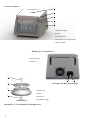
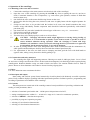
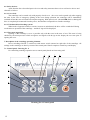
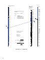
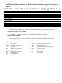
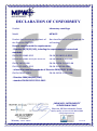
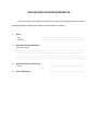
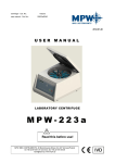
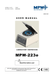
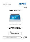
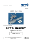
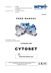
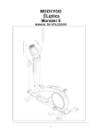
1 Serial number ................................... Production year ................................. “MPW MED. INSTRUMENTS” SPÓŁDZIELNIA PRACY 46 Boremlowska Street 04-347 Warsaw/Poland Phone: (+48 ) 22 610 81 07 Service Fax: (+48 ) 22 610 55 36 07-12-2010 USER MANUAL Instruction catalogue number: 20055x/Eng LABORATORY CENTRIFUGE (MICROCENTRIFUGE) M P W – 55 Centrifuge catalogue number: 10055x Read this instruction before using the equipment! Contents 1. APPLICATION. 5 2. TECHNICAL DATA. 5 2.1. ACCESSORIES. 6 2.1.1. BASIC ACCESSORIES (BEING ENCLOSED TO EVERY CENTRIFUGE). 2.1.2. OPTIONAL ACCESSORIES. 6 6 2.2. EXPLOITATION MATERIALS. 7 3. INSTALLATION. 7 3.1. UNPACKING OF THE CENTRIFUGE. 3.2. LOCATION. 3.3. CONNECTION TO MAINS. 3.4. FUSES. 7 7 7 7 4. DESCRIPTION OF THE CENTRIFUGE. 7 4.1. GENERAL DESCRIPTION. 4.2. SERVICE ELEMENTS. 7 8 5. SAFE WORKING CONDITIONS. 9 5.1. SERVICING PERSONNEL. 5.2. GUARANTEE AND OPERATIONAL USE PERIOD. 5.3. SAFEKEEPING PERIOD. 5.4. HINTS ON CENTRIFUGING. 5.5. HAZARDS AND PRECAUTIONS 9 9 9 9 10 6. OPERATION OF THE CENTRIFUGE. 11 6.1. MOUNTING OF THE ROTOR AND ACCESSORIES. 6.2. CONSTRUCTION AND SAFETY MEASURES. 6.3. DRIVE. 6.4. DATA INPUT AND OUTPUT. 6.5. CONTROLS. 6.6. SAFETY DEVICES. 11 11 11 11 11 12 6.6.1. COVER LOCK. 6.6.2. UNBALANCED LOAD CHECKING SYSTEM. 6.6.3. REST STATE INSPECTION. 12 12 12 2 7. DESCRIPTION OF THE CENTRIFUGE OPERATING ELEMENTS. 12 7.1. CONTROL PANEL - DRAWING NO. 4. 7.2. SWITCHING THE CENTRIFUGE ON. 7.3. SWITCHING THE CENTRIFUGE OFF. 7.4. MATHEMATICAL RELATIONS. 12 15 15 15 7.4.1. RCF – RELATIVE CENTRIPETAL FORCE. 7.4.2. NOMOGRAPH OF RELATIONSHIP - ROTATIONAL SPEED/CENTRIFUGING RADIUS/RCF – DRAWING NO. 5. PAGE 20 7.4.3. MAXIMUM LOAD. 15 15 15 8. CLEANING, DISINFECTION, MAINTENANCE. 16 8.1. CLEANING OF THE CENTRIFUGE. 8.2. CLEANING OF THE ACCESSORIES. 8.3. STERILIZATION AND DISINFECTIONS OF THE ROTATIONAL CHAMBER AND ACCESSORIES. 16 16 17 9. EMERGENCY CONDITIONS – SERVICE. 18 9.1. FAULT FINDING. 9.2. WORK SAFETY INSPECTION. 9.3. INSPECTION PROCEDURES CARRIED OUT BY THE OPERATOR. 18 18 19 10. REPAIR CONDITIONS. 19 11. DISPOSAL. 19 12. MANUFACTURER’S DATA. 19 13. DISTRIBUTOR INFORMATION. 19 14. TABLE OF CHEMICAL RESISTANCE TO THE INTERACTION OF VARIOUS CATEGORIES OF REAGENTS OF PLASTICS 21 3 Warning sings and hazard icons. WARNING Warning of potential injury or health risk. DANGER Risk of electric shock with potential for severe injury or death as a consequence. DANGER Biohazard with potential for risk to health or death as a consequence. DANGER Risk of explosion with potential for severe injury or death as a consequence. 4 1. Application. The MPW-55 centrifuge is a laboratory microcentrifuge for in vitro diagnostic (IVD) equipped with, used to separation of samples took from people's, animal’s and plant’s components with different densities, to provide information about their biological state under the influence of the centrifugal force. Its construction ensures easy operation, safe work and wide range of applications at laboratories engaged in routine medical analyses, biochemical research works etc. This centrifuge is not biotight and therefore during centrifugation of preparations requiring biotightness one has to use closed and sealed rotors. In the centrifuge, it is prohibited to centrifuge caustic, inflammable and explosive preparations. 2. Technical data. Manufacturer: MPW MED. INSTRUMENTS 46 Boremlowska Street, 04-347 Warsaw/Poland Type: MPW-55 Mains L1+N+PE V/Hz ±10% Maximum power consumption Rotational speed range Maximum capacity Maximum acceleration Time range Acceleration Deceleration Programs SHORT – short duration operation Interference level Noise level 100÷230 V 50/60 Hz 95 W 100÷14500 rpm 48 ml 15279 x g 15 s÷99 min 45 s, with 15 s interval and ∞ 3 linear characteristics 3 linear characteristics 9 PN-EN-55011 56 dB Physical data: Depth Width Height Weight 270 mm 220 mm 180 mm 5 kg Environmental conditions: Ambient temperature Relative humidity at ambient temperature Installation category Degree of pollution Protection zone PN-EN-61010-1 p. 1.4.1. +2º ÷40 C 80 % II PN-EN 61010 -1 2 PN-EN 61010 - 1 300 mm Statement of Conformity: The following machine is in accordance with the regulations of the EU Directive 98/79/EC and with the harmonized standards PN-EN 61010-1 and PN-EN 61010-2-020. 5 2.1. Accessories. 2.1.1. Basic accessories (being enclosed to every centrifuge). Cat. No. 17168 17099T 17162 17860 17866 17867 20055x/Eng Type of accessories Complete clamp Spanner for the rotor Spanner for emergency opening of the cover Fuses WTA-T 3,15 A 250 V (230V) Power cord 230 V or Power cord 115 V Operating Instruction pcs 1 pcs 1 pcs 1 pcs 2 pcs 1 pcs 1 pcs 1 2.1.2. Optional accessories. Depending on customer’s needs the MPW-55 centrifuge can be provided with below specified accessories: ROTORS Cat. No Type of rotor Angle 11201a 11202a 11203a 11204a 12205 Angle rotor HS Angle rotor HS Angle rotor HS Angle rotor HS Swing out rotor 45o 45o 45o 45o Rotor capacity (2x8, 2x4)x0,2 ml 12x2/1,5 ml 18x0,5 ml 24x2/1,5 ml 24 capillaries 1,3x50 mm, 19 μl Max rpm RCF 14500 14500 14500 14500 14500 13163 14339 13868 15279 14574 rmax rmin [cm] [cm] 5,6 3,8 6,5 3,0 5,9 3,8 6,5 2,5 6,2 1,2 Displayed RCF is being converting for the radius of the rotor 11204a. RCF parameter for the other rotors is being presented above. ROUND CARRIERS Catalog no Application 14084 14133 14134 Round carrier 11 for 0,5 ml test tubes ( 8,0x30 mm); Round carrier 10,8 for 0,2 ml test tubes (6,2x21 mm); Round carrier 7,8 for 0,2 ml test tubes ( 6,2x21 mm); TEST TUBES Catalog no Specification 15011 15098 15101 15122 15125 15127 15128 15130 15131 Polypropylene round bottom test tube 2 ml with cap ( 10,8x40 mm); Capillary tube stoppers; Microhematocrite capillary tubes, heparinized 50 tape, 19l (1,3x50 mm); Polypropylene PCR test tube 8x0,2 ml ( 6x21 mm); Polypropylene test tube 0,2 ml PCR ( 6x21 mm); Polypropylene test tube 0,5 ml with cap ( 7,8x30 mm); Polypropylene test tube 1,5 ml with cap ( 10,8x39 mm); Polypropylene PCR test tube 8x0,2 ml ( 6x21 mm) ; Polypropylene PCR test tube 4x0,2 ml ( 6x21 mm); OTHER ACCESSORIES Catalog no Specification 16135 16150 Hematocrite reader – flat Hematocrite reader – round 6 2.2. Exploitation materials. For operating in centrifuge one should use only original company’s buckets comprised in the specification of accessories as well as test-tubes for centrifuges of proper diameter, length and strength. Utilization of test-tubes of other makes shall be agreed upon with manufacturer of the centrifuge. For cleaning and disinfecting one should use agents generally applied in the health service, such as e.g. Aerodesina-2000, Lysoformin 3000, Melseptol, Melsept SF, Sanepidex, Cutasept F. 3. Installation. 3.1. Unpacking of the centrifuge. Open the package. Take out the cardboard box containing the accessories. Take out the centrifuge from the package. Keep the package and packing materials at hand for service transport. 3.2. Location. The centrifuge shall not be located near the radiators and shall not be subjected to direct sunlight. The table for the centrifuge shall be stable and shall have flat-levelled table top. It is necessary to ensure a safety zone of the minimum 30 cm round the centrifuge from every direction. Normal operating conditions ambient temperature is from 15 C to 35 C. Passed parameters of the centrifuge are referring to the above named temperatures. At the change of the place from cold to warm one, condensation of water will occur inside the centrifuge. It is important then that sufficient time be provided for drying the centrifuge prior to starting the centrifuge again (minimum 4 hours). 3.3. Connection to mains. Supply voltage given on the rating plate has to be consistent with local supply voltage. MPW MED. INSTRUMENTS laboratory centrifuges are 1st safety class devices and they are provided with the three-core cable with the plug resistant to dynamic loadings. Mains socket shall be provided with the safety pin. It is recommended to install emergency cut-out that shall be located far from the centrifuge, near the exit or beyond the room. Supply voltage 100 230 V 50/60 Hz. Before switching on, check whether the centrifuge is connected to power supply correctly. Check centrifuge before usage whether she is installed correctly. 3.4. Fuses. The centrifuge has standard protection with the WTA-T 3,15 A 250 V fuse. Fuse is situated in the plug-in socket unit at back wall of the centrifuge. 4. Description of the centrifuge. 4.1. General description. New generation of MPW MED. INSTRUMENTS laboratory centrifuges is provided with state-of-the-art microprocessor control systems, very durable and quiet asynchronous brushless motors and accessories consistent with requirements of the present-day user. 7 4.2. Service elements. 1 2 3 4 5 1. Inspection glass 2. Cover 3. Control panel 4. Emergency cover open place 5. Power switch Drawing No.1. General view 1. Plug-in socket 2. Fuse base 4 2 3 Drawing No.2.Back of centrifuge 2 1. Motor axle 2. Rotor 1 3. Rotor lid 4. Complete clamp Drawing No. 3. Unit elements of the angle rotor 8 1 5. Safe working conditions. 5.1. Servicing personnel. The MPW-55 laboratory centrifuge can be operated by laboratory personnel after getting acquainted with Operating Instruction. Operating Instruction shall be held all the time near the centrifuge. Operating Instruction must be kept always at hand!!! 5.2. Guarantee and operational use period. Guarantee period for the MPW-55 centrifuge amounts to minimum 24 months. Principles are specified in guarantee certificate. The service life of the centrifuge specified by the manufacturer amounts to 10 years. After termination of guarantee period it is necessary to carry out yearly technical inspections of the centrifuge. Only service personnel authorized by manufacturer may perform the inspections. The manufacturer reserves the right to make modifications to produced goods. 5.3. Safekeeping period. Maximum period of storage of not used centrifuge amounts to 1 year. After this period, a service authorized by manufacturer should carry out technical inspection of the centrifuge. 5.4. Hints on centrifuging. Set the centrifuge in horizontal position on rigid base. Ensure safe positioning location. Ensure free space around the centrifuge (amounting to at least 30 cm left free). Ensure sufficient ventilation. Fix the rotor on the motor axis firmly. Avoid unbalance. Load the rotor holes with the same accessories. Centrifugation of the test tubes of different sizes. There is a possibility to centrifuge test tubes of different sizes; however, it is absolutely necessary in such cases that opposite buckets and round carriers be the same. It is necessary to insert test tubes symmetrically on the opposite sides. Fill test tubes outside the centrifuge. Please pay special attention to the quality and proper thickness of the glass test tubes walls. Those shall be test tubes for centrifuges, of proper durability up to 5,000 x g. In order to protect the centrifuge against unbalance, fill in the test tubes up to the same weight. Use only accessories in good condition. Protect equipment against corrosion using accurate preventive maintenance. Infectious materials could be processed in closed rotors only. It is not allowed to centrifuge explosive and inflammable materials. It is not allowed to centrifuge substances prone to reacting in result of supplying high energy during centrifugation. 9 5.5. Hazards and precautions Prior to switching the centrifuge on, one shall read carefully all sections of this instruction in order to ensure smooth operation and avoid damages of this device or its accessories. Centrifuge shall not be operated by unqualified laboratory personnel. Centrifuge must not be transported with the rotor mounted on the shaft. One must use original rotors, test-tubes and spare parts only. In the case of faulty operation of the centrifuge one shall ask of assistance of service of MPW Med. instruments Company or its authorized representatives. It is not allowed to switch the centrifuge on if it is not installed properly or rotor is not fitted correctly. The centrifuge must not be operated in places where explosion hazard appears as it is not explosion-proof make. It is not allowed to subject to centrifugation materials, which subjected to action of air, could generate inflammable or explosive mixtures. It is prohibited to subject to centrifugation toxic or infectious materials with damaged leak proof seals of the rotor or test-tube. Proper disinfections procedures have to be carried out when dangerous substances contaminated the centrifuge or its accessories. It isn't allowed to open the cover manually in emergency procedure when rotor is still turning. It isn't allowed to exceed load limit set by the manufacturer. Rotors are intended for fluids of average homogeneous density equal to 1.2 g/cm3 or smaller when centrifugation is carried out at maximum speed. When fluids of higher density shall be used, then it is necessary to limit speed (see point 7.4.3 “Maximum load”). It isn't allowed to use the rotors and round carriers with signs of corrosion or other mechanical defects. It is not allowed to centrifuge highly corrosive substances which may cause material impairment and lower mechanical properties of rotor and round carriers. It isn’t allowed to use rotors and accessories not admitted by the manufacturer. Let to use commercial glass and plastic test tubes, which are destined to centrifuging in this laboratory centrifuge. One should absolutely not use poor quality elements. Cracking of glass vessels and test tubes could result in dangerous vibration of the centrifuge. 10 It isn’t allowed to carry out centrifugation with the rotor caps with taken off or not driven tight. It isn’t allowed to lift or shift the centrifuge during operation, and rest on it. It isn’t allowed to stay in the safety zone within 30 cm distance around the centrifuge neither leave within this zone some things, e.g. glass vessels. It isn’t allowed to put any objects on the centrifuge. 6. Operation of the centrifuge. 6.1. Mounting of the rotor and accessories. 1. 2. Connect the centrifuge to the mains (master switch on back side of the centrifuge). Open the cover of the centrifuge by pressing the COVER key. Prior to putting the rotor in, one has to check if rotational chamber is free of impurities, e.g. such as dust, glass splinters, residues of fluids that must be taken away. 3. One shall fit the rotor on the motor shaft driving it home on the cone. 4. Screw-in the bolt for fixing the rotor (clockwise) and screw it tightly home with the supplied spanner for the rotor. 5. Swing-out rotors have to be provided with the buckets in all seats. One should remember that every buckets swings individually. Bucket suspension studs should be lubricated periodically with technical petroleum jelly. 6. One should use only test tubes intended for selected types of the rotor - see p. 2.1. “Accessories”. 7. Fill test tubes outside the centrifuge. 8. Put on or screw the caps on rotors. 9. Test tubes have to be filled properly in order to avoid overflows. 10. CAUTION: Centrifuge will tolerate small weight differences occurring during loading of rotors. However it is recommended to equalize vessels loads as much as possible in order to ensure minimal vibrations during operation. When the centrifuge is started with large imbalance, the unbalance control system will switch-off the drive system and error signal will be transmitted. On the monitoring panel, U sign will be displayed. 11. In order to prolong lifetime of the rotor and gaskets rotors shall be lubricated with the maintenance oil, while gaskets and threaded parts shall be lubricated with the technical petroleum jelly. 12. For replacement of the rotor one shall unscrew clamping and then grab the rotor with both hands at opposite sides, taking it away from drive shaft by pulling it up. 6.2. Construction and safety measures. The centrifuge has rigid self-supporting structure. Housing was made of ABS type plastic. Cover is fixed on steel axles of hinges and from the front is locked with electromagnetic lock blocking possible opening during centrifugation. Rotation chamber casing was made of thick steel sheet. The rotation chamber bowl is made of plastic. Rotors are from aluminum and reductive inserts from the polypropylene. 6.3. Drive. Low noise induction motor constitutes the drive. 6.4. Data input and output. Data setting and read-out system forms hermetically closed keyboard with distinctly accessible operation points. Easily readable displays signalling individual performed operations facilitate operator’s programming and recording of parameters and condition of the centrifuge. 6.5. Controls. The microprocessor control unit of the centrifuge ensures broad possibilities of providing, realisation and reading of work parameters, that is: selection of rotational speed within 100 14500 rpm at 100 rpm interval or RCF; setting centrifugation time within 15 s ÷ 99 min 45 s range at 15 s interval or continuous operation; selection of SHORT – short duration operation; possibility to program 9 operation programs; selecting of 3 acceleration characteristics selecting of 3 deceleration characteristics 11 6.6. Safety devices. Apart from the above described passive devices and safety measures there exist as well active devices and elements as follows: 6.6.1. Cover lock. The centrifuge can be started only with properly closed cover. , the cover can be opened only after stopping the rotor. In the case of emergency opening of the cover during operation, the centrifuge will be immediately switched-off and the rotor will brake till complete stopping. With opened cover (the COVER diode is shining) the drive is completely disconnected from the power, which makes it impossible to start the centrifuge. 6.6.2. Unbalanced load checking system. When loads of opposite buckets or carriers in rotors are unbalanced, the drive will be switched-off during acceleration or operation of the centrifuge – and the U sign will be displayed. 6.6.3. Rest state inspection. Opening of the centrifuge’s cover is possible only with the rotor in the state of rest. This state is being checked by the microprocessor which recognizes and signals with S sign on the display the rest state prior to opening the cover. 7. Description of the centrifuge operating elements. Power switching ON/OFF is carried out with master switch situated on right side of the centrifuge. All settings on the centrifuge are done by means of the control panel. Panel comprises control keys and display. 7.1. Control panel - Drawing No. 4. For controlling centrifuge operation serves control panel placed on front casing wall. 13. 5. 6. 7. 8. 9. 1. 10. 2. 11. 3. 12. 4. Drawing No.4. Control panel 12 Control panel comprises following elements: START key [element No.11] can be used to: — starting the centrifugation program with the parameters displayed on display, blinking LED on the START key [element No. 8] signaling rotary motion of rotor. The centrifuge can be activated if: the cover is closed (showing up of sign of the dot on the display [element No.13 ]), the LED is not shining on the COVER key [element No.9] STOP key [element No. 12] serves for aborting the actually running operation: interrupting centrifugation program in any program phase and braking the rotor. After pressing the key will occur arrow ↓ on the display which indicated the rotor deceleration and the number of the deceleration mode, finishing of braking rotor process – on the display will shine sign S (Stop) also signalling this state by sound. COVER key [element No. 10] serves for: open the centrifuge cover, Open or incorrectly closing the cover is signalling by LED shining, key is active only if the rotor is not centrifuging, The cover can be opened only if rotor is stopped, on the display will be displayed sign S and the centrifuge will signal possibility of opening cover by short five sounds. ATTENTION: It is not possible to open of the centrifuge at moment when the sign = signalling of possibility to change the parameter value is active, even in spite of the stopped rotor. SHORT key [element No. 7] serves for: short duration operation of the centrifuge in time of holding down the key till moment of it’s releasing, the rotor of Short mode accelerates to speed value setting in the program, accelerating and decelerating of rotor is in accordance with programmed characteristics, pressing the STOP key after releasing SHORT key during the braking of rotor will cause quicker braking of rotor according to characteristic No.1, the centrifugation time in Short mode is measured in minutes and seconds from the start of the centrifuging (pressing the SHORT key) to the rotor stop. The field of functional keys serves for change the program as well for setting it’s individual parameters such as: speed, RCF, time, acceleration and deceleration mode. After pressing the key, the sign equal “=”appears on the display. It means that the value of given parameter can be changed by key: arrow down or arrow up. The possibility of changing the value of parameter is signalling by sign = and is active for a three seconds. It is time, when one should accede to set the demanded value. After three seconds from the setting of the demanded value of given parameter, this value will be saved in the program or after selection the given program will be set as active. Decreasing key, arrow down [element No. 2] serves for: decreasing the values of parameters. Increasing key, arrow up [element No. 1] serves for: increasing the values of parameters. 13 key [element No. 3] serves for: selecting the possibility of changing the centrifuging speed – SPEED next pressing of the key switching-over the programming mode from speed to RCF values. key [element No. 4] serves for: programming the centrifuging time in minutes from 15 s to 99 min 45 s. Setting the sign --m--s over the 99 m 45 s, it will cause the continuous operation of the centrifuge. key [element No. 6] serves for: programming the rotor acceleration ACC and deceleration DEC characteristics. The rotor acceleration characteristic is represented with a arrow up ↑. Pressing this key again will result in switching from rotor acceleration programming mode to rotor deceleration programming mode. The rotor deceleration characteristic is represented with a arrow down ↓. The user can select three deceleration and acceleration characteristics. Characteristics with number 1 are the fastest. key [element No. 5] serves for: selecting program number which will be realized or reprogrammed, It is possible to save the nine programs, Sound signal sound signal is an appendix of the information given by optical path. one short signal – confirmation of the made command (e.g. increasing parameter and such) two short signals – signalling the impossibility of the made command (e.g. increasing the centrifuging speed above 14500) one long signal – signalling the start of the following processes: breaking after pressing the STOP key, beginning the centrifuging operation in Short mode and breaking after releasing the SHORT key, five short sounds – stopping the rotor and possibility to open the cover, five short sounds and one long signal – signalling readiness after switching the supply on. LCD display The centrifuge has readable display LCD, on which are showing information being referred to the actual condition of the system. The information about the centrifuge type, program version and internet address are displaying at once after switching supply on for three seconds. MPW – 55 v.1.91 www.mpw.pl following the information about program has been lately made, the time, speed and acceleration characteristic settings will be displayed. speed S:14500 time T: 99m00s deceleration or acceleration characteristic number 14 program number (1) ↑1 S ■ sign S means the rotor is stopped the underline sign – rotor is working the ■ sign means that the cover is closed, and the means the cover is open after pressing the key twice [element No. 3 on Drawing 4.] the display shows the acceleration value corresponding to the programmed speed RC:14243 (1) T = 99m00s ↑1 S ■ The “=”sign means that the given parameter can be modified During operation of the centrifuge one cannot change the program parameters, but only interrupt its further realization with pressing the STOP key, [element No.12]. 7.2. Switching the centrifuge on. After acquainting with operation elements, programming and preparing the centrifuge to operation one shall set the program, next close the cover and press the START key. The centrifuge will start and realize the programmed program. 7.3. Switching the centrifuge off. The centrifuge is automatically switching off when the program will be realized. It is possible to finish earlier the realization of given program by pressing the STOP key. After ending the centrifugation process one should remember to switch off the centrifuge using the main switch being located from the side of centrifuge. 7.4. Mathematical relations. 7.4.1. RCF – relative centripetal force. RCF acceleration is the acceleration generated by the rotary motion of the rotor acting upon tested product and it can be calculated according to the formula: RCF = 11,18 x r x (n/1000)2 RCF [x g], r [cm], n [rpm] Depending on the distance of particles of the tested product from the axis of rotation, one can establish with use of the above formula the minimum RCF, average RCF or maximum RCF. On the basis of preset RCF value and given radius of the bottom of the bucket one can calculate with it the rotational speed to be set in the program of centrifuging. Selection of the time of sedimentation and the RCF value shall be carried out experimentally for any given product. Once every 100 rpm, an electronic circuit automatically calculates and displays RCF value. In order to program required RCF value one shall use nomograph (Drawing No. 5) or change the rotational speed, matching displayed value to required acceleration value. 7.4.2. Nomograph of relationship - rotational speed/centrifuging radius/RCF – Drawing No. 5. page 20 7.4.3. Maximum load. In order to avoid overloading of the rotor one shall observe maximum load which is recorded on every rotor. Maximum permissible load is reached when all test-tubes are filled with the fluid with 1.2 g/cm3 density. If density of the centrifuged liquid is higher than 1.2 g/cm3, then test-tubes could be filled only partially or one shall limit operation speed of the centrifuge, which is being calculated from the formula: n perm = n max * 1,2 ; G = specific gravity 3 ; cm n max [maximum rotational speed - rpm] 15 8. Cleaning, disinfection, maintenance. CAUTION! It is necessary to use protective gloves during following work. 8.1. Cleaning of the centrifuge. For cleaning, water with soap or other water soluble mild detergent shall be used. One should avoid corrosive and aggressive substances. It is prohibited to use alkaline solutions, inflammable solvents or agents containing abrasive particles. Using wiping cloth, remove condensate or residues of the products from the rotor chamber. It is recommended to keep the cover opened when the centrifuge does not work in order to expel the moisture. In the case the user decides to use centrifuge and equipment cleaning methods other than the ones described in this manual, the user shall contact the device manufacturer in order to check whether the cleaning method chosen does not damage the device. 8.2. Cleaning of the accessories. In order to ensure safe operation one shall carry out in regular way periodical maintenance of the accessories. Manufactured rotors and round carriers have to withstand steady high stresses originating from the field of gravitation. Chemical reactions as well as corrosion (combination of variable pressure and chemical reactions) can cause corrosion or destruction of metals. Hard to observe surface cracks increase gradually and weaken material without visible symptoms. In the case of observation of surface damage, crevice or other change, as well as the corrosion, the given part (rotor, carrier etc.) shall be immediately replaced. In order to prevent corrosion one has to clean regularly the rotor with the fastening bolt and round carriers. Cleaning of the accessories shall be carried out outside of the centrifuge once every week or still better after each use. Then, those parts shall be dried using soft fabric or in the chamber drier at ca. 50 C. Especially prone to the corrosion are parts made of aluminium. For cleaning them one should use neutral agent of pH value from 6 to 8. It is forbidden to use alkaline agent of pH above 8. In this way, the useful service life of the device is substantially increased and susceptibility to corrosion is diminished. Accurate maintenance increases the service life as well and protects against premature rotor failures. Corrosion and damages resulting from insufficient maintenance could not be subject of claims lodged against the manufacturer. 16 8.3. Sterilization and disinfections of the rotational chamber and accessories. One can use all standard disinfectants. The centrifuges and accessories are constructed from various materials and one should to take into account possible variety of materials (see p. 6.2). During sterilization by means of steam one should to consider temperature resistance of individual materials. STERILIZATION Sterilization* Radiation – β/γ Gas Chemical compounds temp. 121 oC, 25 kGy (ethylene oxide) (formalin, ethanol) time 20 min no yes no yes PS no no yes yes SAN no yes no yes PMMA 1) yes yes yes yes PC 2) no no yes yes PVC yes 1) yes yes yes POM no yes yes yes PE-LD no yes yes yes PE-HD yes yes yes yes PP yes yes yes yes PMP yes no yes yes ECTFE/ETFE yes no yes yes PTFE yes no yes yes FEP/PFA yes yes yes FKM yes yes yes EPDM no no yes yes NR yes no yes yes SI * Laboratory vessels have to be exactly cleaned and rinsed with the distilled water before the sterilization in the autoclave. It is always necessary to remove closures from containers! 1) The frequent steam sterilization reduces mechanical durability! PC test tubes may become useless. 2) Except PVC hoses which are resistant to the steam sterilization in the temperature 121 oC. Abbreviations of names of characterized plastics PS: SAN: PMMA: PC: PVC: POM: PE-LD: PE-HD: PP: PMP: Polystyrene Styrene-acrylonitrile Polymethyl methacrylate Polycarbon Polyvinyl chloride Acetal polyoxymethylenel Low density polyethylene High density polyethylene Polypropylene Polymethylpentene ECTFE: ETFE: PTFE: FEP: PFA FKM EPDM: NR: SI: Ethylene/chlorotrifluoroethylene Ethylene/tetrafluoroethylene Polytetrafluoroethylene Tetrafluoroethylene/perfluoropropylene Tetrafluoroethylene/perfluoroalkylvinylether Fluorcarbon rubber Ethylene propylene diene Natural rubber Silicon rubber For centrifuging infectious materials it is necessary to use hermetically closed buckets, in order to prevent they migration into the centrifuge. Rotors, buckets and round carriers can be sterilized in autoclave with temperature 121 o – 124o C and pressure 215 kPa during 20 min. In the centrifuge, disinfectants and cleaning agents generally used in medical care should be used (e.g. Aerodesina-2000, Lysoformin 3000, Melseptol, Melsept SF, Sanepidex, Cutasept F). User is responsible for proper disinfections of the centrifuge, if some dangerous material was spilled inside or outside of the centrifuge. During the above mentioned works one must wear safety gloves. 17 9. Emergency conditions – service. 9.1. Fault finding. Majority of faults could be removed by switching the centrifuge OFF and then ON. After switching the centrifuge ON, there shall be displayed parameters of the recently implemented program and sound signals comprising four successive tones shall be generated. In the case of short-duration power failure the rotor is decelerate. Please find below the most frequent faults and their repair methods. 1. Lack of the display: Remedies: Is mains socket live ? Check mains socket fuse. Is supply cable plugged into socket ? Plug correctly supply cable. Is input fuse good ? Replace input fuse (rated data on rating plate). Is master switch switched ON ? Switch ON power supply. Above was checked and still there is not display Call service. active. 2. Centrifuge does not start: Remedies: START key pushing does not generate reaction or single tone only P message is displayed Call service LED diode of cover is shining Close cover. The lock has to be locked with typical sound. He has to the sign of the dot appear on the display. If the diode is not switching off one shall call service. LED diode of “Start” key is shining Switch power supply OFF/ON. If fault still persists then call service. The digit of display parameters is blinking Push the “Stop” key which has being recorded program. If fault still persists then call service. 3. Centrifuge starts but does not accelerate Remedies: E symbol displayed after stopping. Drive overload 4. One can not open the cover: Wait for 15 minutes and switch again after opening and closing the cover. Remedies: With the attempt opening cover is audible buzzing of One should lift up till the yellow LED ”Cover” is the lock. switching on. Failed spring of cover lifting or bended the lock striker. One should bend the striker or call service. LED diode “Cover” is not shining and the Lock is failed. Call service. centrifuge not swirling. Emergency cover release In the case of e.g. mains failure it is possible to open the cover by hand. Place the key 17162 into the hole on the right side of the casing and push in. The cover will be opened. The cover can be unlocked and opened only when the rotor is in the rest state. 9.2. Work safety inspection. For safety reasons, inspections of the centrifuge carried out by the authorized service at least once a year after the period of warranty. The reason for more frequent inspections could be corrosion inducing environment. Examinations should end with issuing "Report of validation, the check on the technical state of the laboratory centrifuge". It is being recommended to establish "Technical passport" or "Log of the apparatus", in whom every repairs and reviews are being registered. Both these documents should be stored in the place of use of the centrifuge. 18 9.3. Inspection procedures carried out by the operator. Operator has to pay special attention to the fact that the centrifuge parts of key importance due to safety reasons are not damaged. This remark is specifically important as for: 1. Motor suspension 2. Motor axis concentricity 3. Centrifuge accessories and especially structural changes, corrosion, preliminary cracks, abrasion of metal parts. 4. Screw joints. 5. Inspection of the rotor assembly. 6. Inspection of bioseals of the buckets if such are used. 7. Control of execution of the guarantee yearly technical inspection of the centrifuge Only the manufacturer-specified holders, included in the equipment list, as well as centrifuge capillaries, which diameter, length and durability are suitable, should be used for spinning in this centrifuge. The use of equipment made by other manufacturers should be consulted with the manufacturer of the centrifuge. Disinfectants and cleaning agents generally used in medical care should be used in this centrifuge (e.g. Aerodesina-2000, Lysoformin 3000, Melseptol, Melsept SF, Sanepidex, Cutasept F). 10. Repair conditions. Manufacturer grants to the Buyer the guarantee on conditions specified in the Guarantee Certificate. Buyer forfeits the right to guarantee repair when using the device inconsistently with the Operating Instruction provisions, when damage results from the User’s fault. Repairs should be carried out in authorized service workshops, granted with the MPW Certificate. The centrifuge shall be sent to repair after decontaminating disinfections. Information about authorized service workshops could be obtained from the Manufacturer. 11. Disposal. When you are disposing the device, the respective statutory rules must be observed. Pursuant to guideline 2002/96/EC (WEEE), all devices supplied after August 13, 2005, may not be disposed as part of domestic waste. The device belongs to 8th group (medical devices) and is categorized in business to business field. The icon of the crossed-out trash can shows that the device may not be disposed as part of domestic waste. The waste disposal guidelines of the individual EC countries might vary. If necessary, contact your supplier. 12. Manufacturer’s data. MPW MED. INSTRUMENTS 46 Boremlowska Street, 04-347 Warsaw, Poland . Tel. Fax. (+ 48) 22 610 56 67 Selling (+ 48) 22 610 81 07 Service (+ 48) 22 610 55 36 E-mail: [email protected] www.mpw.pl 13. Distributor information. YOUR DISTRIBUTOR: 19 NOMOGRAM [r.p.m] Centrifuging radius [cm] R.C.F. (x "g") multiple of gravitational acceleration 50 20000 45 50000 40000 15000 14000 13000 12000 11000 10000 30000 9000 100000 40 35 Formula used for calculation of this nomogram : 2 R.C.F.= 11,18 * r * (n/1000) where : 30 29 28 27 26 25 24 23 22 21 20 19 A R.C.F. r n g multiple of gravitational speed centrifuging radius (cm) rotational speed (r.p.m.) gravitational acceleration - 10000 8000 6000 5000 4000 1500 1200 1000 800 16 600 500 400 15 14 300 13 200 Example of making use of the nomogram: 11 10 A=14,4 cm B=4600 r.p.m. C=3400 x g 9 150 120 100 80 60 50 40 30 25 20 8 7000 15000 3000 2400 2000 18 17 12 8000 20000 6000 B 5000 4500 C 4000 3500 3000 2500 2000 1500 1400 1300 1200 1100 1000 900 800 700 600 500 15 7 6 5 n 1000 * r RCF 11,18 * r RCF 2 11 ,18 * n 1000 6 5 4 300 3 200 Drawing No. 5 – Nomograph. 20 400 10 8 14. Table of chemical resistance to the interaction of various categories of reagents of plastics Groups of the substance in temp. 20°C Aldehydes Cyclic alcohols Esters Ether Ketones Strong or concentrated acids Weak or diluted acids Oxidizing acids or oxidizing substances cyclic hydrocarbons Ahs Haloid hydrocarbons Alkalis PS SAN PMMA PC PCV POM PE-LD PE-HD PP PMP ECTFE PTFE ETFE FEP PFA ○ + + FKM EPDM NR SI ○ - - ○ ○ - ○ - + + + + ○ + + + + + + + + + + + + - + + + - - - - - - + ○ ○ ○ + + - ○ ○ ○ - - - - - + + ○ ○ - + + - - - - - - - - - + ○ ○ ○ ○ ○ + - ○ - - ○ - - - + - + + + + + + + - - ○ ○ ○ ○ + - + + + + + + + + ○ ○ - - - - - - - - - - + + ○ ○ - - - - ○ ○ + + + + + ○ + + ○ - - - - - - - - + + ○ ○ - + + ○ - - - - - - - - + + ○ ○ - + + ○ - - - + + - - + + + + + + + + ○ + + ○ + = very good chemical resistance Permanent action of the substance isn't causing damage through 30 days. The material is able to be resistant through years. ○ = chemical resistance of good to limited Continuous action of the substance is causing insignificant damage through the period of 7-30 days, partly reversible (e.g. puffing up, softening, reduced mechanical durability, discoloring). - = limited chemical resistance The material isn't able to have the continuous contact with the substance. The immediate occurrence of damage is possible (e.g. the loss of mechanical durability, the deformation, discoloring, bursting, dissolving). Abbreviations of names of characterized plastics PS: SAN: PMMA: PC: PVC: POM: PE-LD: PE-HD: PP: PMP: Polystyrene Styrene-acrylonitrile Polymethyl methacrylate Polycarbon Polyvinyl chloride Acetal polyoxymethylenel Low density polyethylene High density polyethylene Polypropylene Polymethylpentene ECTFE: ETFE: PTFE: FEP: PFA FKM EPDM: NR: SI: Ethylene/chlorotrifluoroethylene Ethylene/tetrafluoroethylene Polytetrafluoroethylene Tetrafluoroethylene/perfluoropropylene Tetrafluoroethylene/perfluoroalkylvinylether Fluorcarbon rubber Ethylene propylene diene Natural rubber Silicon rubber 21 DECLARATION OF CONFORMITY Product Laboratory centrifuge Model MPW-55 Product classification on the basis of the Directive 98/79/EC Non classified to list A or B and not for self-testing Product complies with the requirements: · Directive 98/79/EC (IVD), including the requirements of harmonised standards: PN-EN ISO 13485:2012 PN-EN ISO 18113-3:2011 PN-EN ISO 13485:2012/AC:2013-03 PN-EN 61010-2-101:2005 PN-EN 13612:2006 PN-EN 61326-2-6:2013-08 PN-EN ISO 14971:2012 PN-EN ISO 62366:2008 · selected harmonized standards of Directive 2006/95/EC (LVD): PN-EN 61010-1:2011 PN-EN 61010-2-020:2008 · Directive 2004/108/WE (EMC) · standard PN-EN ISO 15223-1:2012 „MPW MED. INSTRUMENTS” SPÓŁDZIELNIA PRACY Warsaw, 46 Boremlowska Street Quality policy in line with ISO 9001:2008 Certifying authority Warsaw, 13.11.2014 nr 10.055.03 DECLARATION OF DECONTAMINATION In order to protect our employees please fill out the declaration of decontamination completely before sending centrifuge to the manufacturer (repair). 1. 2. Device ─ type: ……………………………………………………………………………………… ─ serial No.: ……………………………………………………………………………………… Description of decontamination (see user manual) ……………………………………………………………………………………………………………………………………………… ……………………………………………………………………………………………………………………………………………… ……………………………………………………………………………………………………………………………………………… ……………………………………………………………………………………………………………………………………………… 3. 4. Decontamination carried out by: ─ name: ………………………………………………………………………… Date and signature ………………………………………………………………………… DECLARATION OF DECONTAMINATION In order to protect our employees please fill out the declaration of decontamination completely before sending centrifuge to the manufacturer (return). 5. 6. Device ─ type: ……………………………………………………………………………………… ─ serial No.: ……………………………………………………………………………………… Description of decontamination (see user manual) ……………………………………………………………………………………………………………………………………………… ……………………………………………………………………………………………………………………………………………… ……………………………………………………………………………………………………………………………………………… ……………………………………………………………………………………………………………………………………………… 7. 8. Decontamination carried out by: ─ name: ………………………………………………………………………… Date and signature …………………………………………………………………………